Adjusting instructions and illustrated parts list
|
|
|
- Spencer Hunter
- 5 years ago
- Views:
Transcription


1 CATALOG NO. 29M Adjusting instructions and iustrated parts ist Fifth Edition CLASSES ,.., u Serie s Advanced, high speed, f at bed machines Finest Quaity


2 CATALOG NO. 29 M ADJUSTING INSTRUCTIONS AND ILLUSTRATED PARTS LIST FOR SERIES ADVANCED, HIGH SPEED FLAT BED MACHINES STYLES H K L R S W E F G H M N R U W X AH AL D P R S T W X A B C J R U J H J P R Fifth Edition 965, 982 By Union Specia Corporation Rights Reserved in A Countries Printed in U.S.A. March, 982 2
 Advanced high speed, ow or medium throw, fat bed machines.")

3 IDENTIFICATION OF MACHINES Each UNION SPECIAL machine carries a Stye number, which on these Casses of machines, is stamped into the stye pate affixed to the right front of machine. The seria number is stamped in the casting at the right rear base of machine. CLASS DESCRIPTION (56200) Advanced high speed, ow or medium throw, fat bed machines. Singe neede, one ooper, encosed automatic ubricating system. Maximum reconmended speed 6500 R.P.M. Maximum work space to right of neede bar 8 /4 inches (209.6mm). MACHINE STYLES H Low throw machine. Typica appication - For misceaneous seaming operations on ight to medium weight wash and wear materias where chaining and a short stitch are required. Seam specification 40 SSa-. Type 0 GS neede K Low throw machine. Typica appication - For binding aprons and dresses made with ight to medium weight materias. Seam specification 40 BSc-. Type 06 GLS neede. Uses cut edge binding 3/4, 7/8,, /8, /4 inch (9.0, 22.2, 25.4, 28.6, 3.8nm) wide and produces a 7/32, /4, 9/32, /32, 3/32 inch (5.6, 6.4, 7., 8.7, 0.3mm) finish, respectivey. #56200 L Medium throw machine. Typica appication - For binding mattress ticks made with medium to medium heavy weight materias. Seam specification 40 BSa-. Type 26 GS neede. Uses sevage edge binding 5/8, 3/4, 7/8 inch (5.9, 9.0, 22.2mm) wide and produces a 5/6, 3/8, 7/6 inch (7.9, 9.5,.mm) finish, respectivey. *56200 R Low throw machine. Typica appication - For joining shouders of shirts in one operation made with ight to medium weight materias. Seam specification 40 LSe-. Type 06 GLS neede S Low throw machine. Typica appication - For misceaneous operations on woven materias, knitted drawer bands, knitted shirt fronts made with ight to medium weight materias. Seam specification 40 SSa-. Type 08 GHS neede W Medium throw machine. Typica appication - For seaming cotton fanne and eather pam goves. Seam specification 40 SSa-. Type 28 GAS neede. CLASS DESCRIPTION (56300) Advanced high speed, medium or high throw, fat bed machines. Singe neede, one ooper, encosed automatic ubricating system. Maximum work space to right of neede bar 8 /4 inches (209.6mm). #Discontinued - Repaced by Stye M. *Discontinued - In most instances, repacement parts are avaiabe. 3
4 CLASS DESCRIPTION (56300 Continued) MACHINE STYLES E Medium throw machine, equipped with thumbscrew adjustabe frame neede thread eyeet, automatic chain cutter and pressure reease attachment. Typica appication - For seaming trousers and coats made with medium to medium heavy weight materias. Seam specification 40 SSa-. Type 28 GBS neede. Maximum reconmended speed 6500 R.P.M F Medium throw machine, equipped with thumbscrew adjustabe frame neede thread eyeet and a feeding presser foot. Typica appication - For seaming trousers and coats made with medium to medium heavy weight durabe press materias. Seam specification 40 SSa-. Type 28 GBS neede. Maximum recommended speed 6500 R.P.M G Medium throw machine, equipped with thumbscrew adjustabe frame neede thread eyeet. Typica appication - For seaming trousers, coats and simiar garments, made of medium to medium heavy weight materias. Seam specification 40 SSa-. Type 28 GBS neede. Maximum recommended speed 6500 R.P.M H High throw machine. Typica appication - For seaming couch covers, with or without rope wet made with medium heavy to heavy weight materias. Wet guided to the eft of neede. Seam specification 40 SSa- or 40 SSk- modified. Type 43 GS neede. Maximum recommended speed 6000 R.P.M M High throw machine. Typica appication - For binding mattress ticks made with medium heavy to heavy weight materias. Seam specification 40 BSa-. Type 26 GS neede. Uses sevage edge binding 5/8, 3/4 and 7/8 inch (5.8, 9.0 and 22.2mm) wide, and produces a 5/6, 3/8 and 7/6 inch (7.9, 9.5 and.mm) finish respectivey. Maximum recommended speed 6000 R.P.M N Medium throw machine, equipped with thumbscrew adjustabe frame neede thread eyeet and top-grip feed mechanism. Typica appication - For edge seaming operations on trousers, sacks, dress pants, jackets made of ight to medium weight durabe press materias. Maximum seam width is inch (25.4mm) necessitated by the top-grip-feed mechanism. Seam specification 40 SSa-. Type 28 GBS neede. Maximum recommended speed 6500 R.P.M R Medium throw machine, equipped with thumbscrew adjustabe frame neede thread eyeet and feeding presser foot. Typica appication - For seaming side and inseams on trousers, back and side seams on coats, seeve seams on jackets, coats made with medium to medium heavy weight materias. Seam specification 40 SSa-. Type 28 GBS neede. Maximum recommended speed 6500 R.P.M. *56300 U Medium throw machine, equipped with thumbscrew adjustabe frame neede thread eyeet and top-grip-feed mechanism. Typica appication - For edge seaming operations on trousers, sacks, dress pants, jackets and simiar garments made of ight to medium weight materias. Maximum seam width is inch (25.4mm) necessitated by the top-grip-feed mechanism. Seam specification 40 SSa-. Type 28 GBS neede. Maximum recommended speed 6500 R.P.M. *Discontinued - In most instances, repacement parts are avaiabe. 4
5 MACHINE STYLES (Continued) W Medium throw machine, equipped with zipper guiding presser foot for crossing zipper attached to pants fy. Typica appication - For attaching waistbands to men's trousers. Seam specification 40 SSa-. Type 28 GAS neede. Maximum recommended speed 6500 R.P.M. *56300 X Medium throw machine, equipped with thumbscrew adjustabe frame neede thread eyeet, top-grip-feed mechanism and presser foot with yieding section to the eft of neede. Typica appication - For edge seaming operations on trousers, sacks, dress pants, jackets and simiar garments made of ight to medium weight materias. Maximum seam width is inch (25.4mm) necessitated by the top-grip-feed mechanism. Seam specification 40 SSa-. Type 28 GBS neede. Maximum recommended speed 6500 R.P.M AH Medium throw machine, equipped with thumbscrew adjustabe frame neede thread eyeet, top-grip-feed mechanism and presser foot with yieding section to the eft of neede. Typica appication - For edge seaming operations on trousers, sacks, dress pants, jackets ~nd simiar garments made of ight to medium weight durabe press materias. Maximum seam width is inch (25.4mm) necessitated by the top-grip-feed mechanism. Seam specification 40 SSa-. Type 28 GBS neede. Maximum recommended speed 6500 R.P.M AL Medium throw machine, equipped with thumbscrew adjustabe frame neede thread eyeet. Typica appication - For misceaneous operations on paper garments and pastic products requiring a ong stitch. Stitch range is 4 to 7 per inch. Seam specification 40 SSa-. Type 28 GAS neede. Maximum recommended speed 6000 R.P.M. CLASS DESCRIPTION (56400) Advanced high speed, ow throw, fat bed machines. Two needes, independent row, eft neede in front, two oopers, encosed automatic ubricating system. Type 06 GHS neede. Prepared for use with knee press for foot ifter. Maximum recommended speed 6500 R.P.M. Maximum work space to right of neede bar 8 /4 inches (209.6mm). MACHINE STYLES D To be used with Gakin cose-couped puer. Attachments not furnished with machine. Typica appication - For hemming and simutaneousy inserting eastic in tops and egs of knitted undergarments made with ight to medium weight materias. Seam specification 40 EFg-2. Standard gauge Nos. 2, P Typica seeves erias. 2, 6, appication - For piecing seeves, joining shouders, setting of ordinary quaity shirts made with ight to medium weight mat Seam specification 40 LSc-2. Standard gauge Nos. 6, 8, 0, R Typica appication - For attaching set-on center paits and interining strip to skirts made with ight to medium weight materias. Starts operating at neck. Seam specification -40 LSm-2. Type 06 GHS neede. Standard gauge 48. Maximum recommended speed 6500 R.P.M. *Discontinued - In most instances, repacement parts are avaiabe. 5
6 MACHINE STYLES (Continued) S Typica appication - For foding and attaching inside button facings to fronts of shirts made with ight to medium weight materias. Start operations at the neck. Facing strip guided next to feed dog. Seam specification 40 LSm-2. Type 06 GHS neede. Standard gauge 48. Maximum recommended speed 6500 R.P.M T Typica appication - For piecing seeves, joining shouders and setting seeves of extra fine quaity shirts made with ight to medium weight materias. Seam specification 40 LSc-2. Type 06 GHS neede. Standard gauge Nos. 8, 0, 2, 6. Maximum recommended speed 6500 R.P.M W Typica appication - For piecing seeves of shirts and pajamas, joining operations on woven shorts made with ight to medium weight materias, where the majority of the work consists of straight seams. Seam specification 40 LSc-2. Type 06 GHS neede. Standard gauge Nos. 8, 0, 2, 6. Maximum recommended speed 6500 R.P.M X Typica appication - For quiting coar bands of shirts made with ight to medium weight materias. 26 gauge is equipped with a foder so that this machine can aso be used for setting seeves on extra fine quaity shirts. Seam specification 40 SSa-2 or 40 LSc-2. Type 06 GHS neede. Standard gauge Nos. 24, 26. Maximum recommended speed 6500 R.P.M. CLASS DESCRIPTION (56500) Advanced high speed, high throw, fat bed machines. Two needes, independent row, two oopers, encosed automatic ubricating system. Maximum work space to right of neede bar 8 /4 inches (209.6rnn). MACHINE STYLES A Typica appication - For seat seaming operations on trousers and simiar garments made of medium heavy to heavy weight materias. Seam specification 40 SSa-2. Type 30 GS neede. Avaiabe for 5 stitches per inch ony. Standard gauge ony. Maximum recornnended speed 6000 R.P.M. ( Formery known as Stye N-5) B Typica appication - For seaming trousers and simiar garments made of medium heavy to heavy weight materias. Seam specification 40 SSa-2. Type 30 GS neede. Avaiabe for 7 stitches per inch ony. Standard gauge ony. Maximum recommended speed 6000 R.P.M. (Formery known as Stye N-7) C Typica appication - For seaming trousers and simiar garments made of medium heavy to heavy weight materias. Seam specification 40 SSa-2. Type 30 GS neede. Avaiabe for 0 stitches per inch ony. Standard gauge ony. Maximum recommended speed 6000 R.P.M. (Formery known as Stye N-0) J Typica appication - For feing overas, coats, combination suits and simiar garments made of medium heavy weight materias. Seam specification 40 LSc-2. Type 28 GS neede. Standard gauge Nos. 6, 8. Maximum recommended speed 6000 R.P.M., depending on materia or operation. 6
7 MACHINE STYLES (Continued) R Typica appication - For attaching risers to dungarees, piecing seeves on denim jackets and for attaching overa bibs made of medium heavy to heavy weight materias. Seam specification 40 LSc-2. Type 28 GS neede. Standard gauge 8. Maximum recommended speed 6000 R.P.M., depending on materia or operation U Typica appication - For seaming trousers made of durabe press materia or medium heavy to heavy weight materias. Seam specification 40 SSa-2. Type 30 GS neede. Avaiabe for 7 stitches per inch ony. Standard gauge ony. Maximum recommended speed 6000 R.P.M. CLASS DESCRIPTION (56700) Advanced high speed, ow throw, fat bed machines. Two needes, independent row, needes abreast, two oopers, encosed automatic ubricating system. Maximum work space to right of neede bar 8 /4 inches (209.6mm). MACHINE STYLE J Equipped with Tru-Front foder. Typica appication - For one operation foding and attaching Set-on center pait and interining strips to fronts of shirts and simiar garments made of ight to medium weight materias. Starts operation at neck. Paits used in garment engths and extends /4 inch (6.4mm) beyond the rows of stitching. Seam specification 40 LSm-2. Type 08 GKS neede. Standard gauge Nos. 56, 64. Maximum recommended speed 6500 R.P.M. CLASS DESCRIPTION (56900) Advanced high speed, high throw, fat bed machines. Three needes, independent row, eft neede in front, three oopers, encosed automatic ubricating system. Maximum recommended speed 6000 R.P.M. Maximum work space to right of neede bar 8 /4 inches (209.6mm). MACHINE STYLES H Typica appication - For setting seeves, shouder seaming on denim jackets made with medium heavy to heavy weight materias. Seam specification 40 LSc-3. Type 28 GAS neede. Standard gauge Nos. 8, J Typica appication - For seaming operations on jackets made of medium heavy to heavy weight materias. Seam specification 40 LSb-3. Type 47 GKS neede. Standard gauge P Typica appication - For attaching risers to the back of jeans made with medium heavy to heavy weight materias. Seam specification 40 LSc-3. Type 47 GKS neede. Standard gauge R Typica appication - For seat seams, outseam or inseam on jeans made from heavy weight denim. Seam specification 40 LSc-3. Type 47 GS neede. Standard gauge 9. 7
8 NEEDLES Each neede has both a type and size number. The type number denotes the kind of shank, point, ength, groove, finish and other detais. The size number, stamped on the neede shank, denotes argest diameter of bade, measured midway between shank and eye. Coectivey, type and size number represent the compete symbo, which is given on the abe of a needes packaged and sod by UNION SPECIAL. To have neede orders prompty and accuratey fied, an empty package, a sampe neede, or the type and size number shoud be forwarded. Use description on abe. A compete order woud read: 000 needes, Type 06 GHS, Size 090/036 The type numbers of the needes recommended for each stye of machine covered by this cataog are given in the machine stye or cass description. Other needes are avaiabe, but the ones indicated are those recorrnnended to produce the most satisfactory resuts. The type numbers of the recommended needes together with their descriptions, and the sizes avaiabe are isted beow: Type 0 GS 06 GHS 08 GHS 08 GKS 26 GS 28 GS 28 GAS 28 GBS 30 GS Description and Sizes Round shank, round point, extra short, doube groove, struck groove, chromium pated - sizes 022, 025, 027, 080/032, 049, 054. Round shank, round point, extra short, doube groove, struck groove, ba eye, ba point, chromium pated - sizes 070/027, 075/029, 090/036. Round shank, round point, extra short, doube groove, struck groove, ba eye, ba point, spotted, chromium pated - sizes 070/027, 075/029, 080/032, 090/036, 00/040 0/044, 25/049. Round shank, round point, extra short, doube groove, struck groove, oversize ba eye, spotted, chromium pated - sizes 080/032, 090/036, 00/040. Round shank, round point, short, doube groove, struck groove, ba eye, chromium pated - sizes 080/032, 00/040, 054. Round shank, round point, short, doube groove, struck groove, ba eye, spotted, undersize eye and groove 27% of size of neede, chromium pated - sizes 090/036, 00/040, 0/044, 25/049, 40/054. Round shank, round point, short, doube groove, struck groove, ba eye, spotted, chromium pated - sizes 080/032, 090/036, 00/040, 0/044, 25/049, 40/054, 50/060, 70/067. Round shank, round point, short, doube groove, struck groove, ba eye, spotted, ba point, chromium pated - sizes 080/032, 090/036, 00/040, 0/044, 25/049, 40/054, 50/060. Round shank, round point, short, doube groove, struck groove, ba eye, spotted, government, chromium pated - sizes 080/032, 090/036, 00/040, 0/044, 25/049, 40/054, 50/060. 8


9 Type NEEDLES (Continued) Description and Sizes 43 GS Round shank, round point, 2 bag, doube groove, struck groove, spotted, chromium pated - sizes 40/054, 50/060, 70/067, 230/ GKS Round shank, round point, ong, doube groove, struck groove, oversize ba eye, spotted, short point, standard eye and grooves, chromium pated - sizes 090/036, 00/040, 0/044, 25/049, 40/054. Seection of proper neede size is determined by size of the thread used. Thread shoud pass freey through neede eye in order to produce a good stitch formati,'on. LUBRICATION Use a straight minera oi with a Saybot viscosity of 90 to 25 seconds at 00 degrees F. This is equivaent to Union Specia Corporation Specification 75. Before operating, fi machine with oi at pug screw (A, Fig. ). Whie fiing machine with oi, check gauge (B). When proper oi eve is reached, gauge neede wi register on back ine marked FULL Oi must be added when gauge neede registers on back ine marked "LOW'. Athough the machine can be operated safey when gauge neede registers in the "OPERATE" zone, it is recommended to aways check oi eve before operating, to be sure machine is fied with oi to the "FULL" mark. CAUTION: DO NOT over fi machine. To drain oi, remove pug screw (C), or ower crank chamber cover on back of machine. Oi must be changed every 2000 operating hours to minimize wear. On new machines, or a machine out of service for an extended period of time; ubricate machine as foows: Remove head cover, cean.out int, then directy oi neede bar ink and neede bar. Repace head cover and fi machine with oi to proper eve. Run machine at ow RPM to ensure proper ubrication of components preventing any damage which may occur from ack of oi distribution. Fig. 9


10 FIii main reservoir here. CAUTION: FIii o reservoir before starting. Machine has been drained before shipping. fu mark on gauge. Fig. 2 THREADING AND OILING DIAGRAM FOR ALL STYLES EXCEPT E,F,G,N,R,U,X,AH and AL Oi has been drained from machine before shipping and the reservoir must be fied before starting to operate. Maintain oi eve in "OPERATE" zone; add oi when neede of gauge registers on the back ine marked "LOW". Machine is automaticay ubricated and no oiing other than keeping the main reservoir fied is necessary. Refer to instructions under LUBRICATION and "CHANGING STITCH LENGTH" for additiona information. Thread machine as iustrated above for a Styes except E,F,G,N,R,U,X, AH and AL. 0


11 FIii main reservoir here. CAUTION: Fi o reservoir before starting. Machine has been drained before shipping. FIii reservoir to fu mark on gauge. CAUTION: Be sure ooper connection Is up before sewing. Fig. 2A THREADING AND OILING DIAGRAM FOR STYLES E,F,G,N,R,U,X,AH and AL Oi has been drained from machine before shipping and the reservoir must be fied before starting to operate. Maintain oi eve in 0PERATE zone; add oi when neede of gauge registers on the back ine marked LOW Machine is automaticay ubricated and no oiing other than keeping the main reservoir fied is necessary. Refer to instructions under LUBRICATION and "CHANGING STITCH LENGTH" for additiona information. Thread machine as iustrated above for Styes E,F,G,N,R,U,X,AH and AL.

 and tip machine forward to drain a oi from reservoir. - Remove ower crank chamber cover on back of machine. - Fi reservoir unti oi is even with bottom of knee press shaft bushing (D).")
12 ADJUSTING INSTRUCTIONS NOTE: Instructions stating direction or ocation, such as right, eft, front or rear of machine, are given reative to operator's position at the machine. The handwhee rotates countercockwise, in operating direction; when viewed from the right end of machine. OIL GAUGE CALIBRATION To recaibrate oi gauge, foow instructions in sequence as isted: - Pace machine upright on a eve surface. - Remove pug screw (C, Fig. ) and tip machine forward to drain a oi from reservoir. - Remove ower crank chamber cover on back of machine. - Fi reservoir unti oi is even with bottom of knee press shaft bushing (D). - Loosen ocknut (E) and rotate caibrating screw (F) as required unti gauge neede registers on the back ine marked LOW - Tighten ocknut {E), then repace pug screw (C) and ower crank chamber cover. - Fi machine with oi unti gauge neede registers on back ine marked FULL A NEEDLE BAR ALIGNMENT (TWO AND THREE NEEDLE MACHINES) Insert a new set of needes (type and size required). Turn handwhee to bring neede bar (A, Fig. 3) down to ensure that needes center in neede hoes of throat pate as shown in Fig. 3. Adjustment can be made by oosening screw (B) sighty, aowing neede bar to be turned as required. Tighten camp screw. SYNCHRONIZING LOOPER AND NEEDLE MOTIONS Insert ooper into the ooper rocker, Fig. 3 pushing it a the way down and tighten screw against fat on shank of ooper. Turn handwhee in operating direction unti the point of the ooper (A, Fig. 4) moving to the eft, is even with the eft side of the right neede (B). Note the height of the eye of the neede with respect to the ooper point (See Fig. 5). Turn the handwhee in the reverse direction unti the point of ooper again moving to the eft, is even with the eft side of right neede (See Fig. 5). If the height of the eye of the neede with respect to the ooper point are the same, ooper and neede motions are synchronized - a variation of.005 inch (.27mm) is aowabe. Fig. 4 2
 dimension shown in Fig.")
.")
13 SYNCHRONIZING LOOPER AND NEEDLE MOTIONS (Continued) If the distance from the eye of the neede to the point of the ooper is greater when the handwhee is turned in the operating direction, the ooper drive ever rocker shaft wi have to be moved sighty towards the rear. Moving the shaft towards the front acts the reverse. NOTE: The /64 inch (.4mm) dimension shown in Fig. 5 is for fina setting of neede bar height. Adjust ooper drive rocker ever shaft as foows: Loosen screw (C, Fig. 4) in ooper drive ever (D). A rod of thd. or Union Specia Screw A can be threaded into the ooper drive ever rocker shaft through the center of thrust adjusting screw (E). Tap or pu sighty as required to position shaft for proper synchronization. Tighten screw (C) securey and remove rod or screw used to position shaft. Loosen ock nut (F) and TORQUE thrust adjusting screw (E) to 6 in. bs. (7cm/kg);re-tighten ock nut (F) securey. With ooper at extreme right end of its trave, check ocation of the centerine of right ooper connecting rod bearing using gauge 2227 ex for a Casses except which uses gauge 2227 CX-56 for Stye J-56 and 2227 CX-64 for Stye J-64. Remove nut from ooper ever stud (A, Fig. 6) and pace hoe in gauge (B) over threaded stud. The eft end of gauge shoud ocate against the RIGHT side of ooper rocker cone (C). If adjustment is necessary, oosen camp screw (D), reposition ooper drive ever (E) as required and retighten screw (D). If gauge is not avaiabe, setting can be checked with a scae. "X" dimension is from centerine of stud (A) to centerine of cone (C) which shoud be 4 /6 inch (03.2mm) for a Casses except Stye J-56 shoud be a 3 5/8 inch (92. nm) and Stye J-64 shoud be 3 9/6 inch (90.6mm) with ooper at extreme right end of trave. For Proper SYNCHRONIZATION of Looper & Neede these two Dimensions wi be the same J /84'H--==- (.4mm) -r in OPERATING Direction Fig. 6 Fig. 5 Looper in FRONT of Neede In REVERSE Direction LOOPER SETTINGS Fig. 7 Insert a new neede, type and size as specified. If the ooper ga_uge is 5/32 inch (4.0nm), for exampe, set the ooper (A, Fig. 7) so the distance from the center of the neede (B) to the point of the ooper is 5/32 inch (4.0mm), when the ooper is at its farthest position to the right. 3

 (it has a eft hand thread) and nut (E) on connecting rod (F), turn the connecting rod forward or backward to obtain the 5/32 inch (4.0mm) dimension.")
14 LOOPER SEITINGS (Continued) Looper gauge /32 (C) can be used advantageousy in making this adjustment. On two neede machines set the back ooper to the right neede and on three neede machines set the midde ooper to the midde neede, when setting the ooper gauge. Refer to chart for neede Type, ooper gauge setting and ooper gauge number. If adjment is required, oosen nut (D) (it has a eft hand thread) and nut (E) on connecting rod (F), turn the connecting rod forward or backward to obtain the 5/32 inch (4.0mm) dimension. Retighten both nuts, first nut (E), then nut (D). Make sure the eft ba joint is in vertica position and does not bind after adjustment. Machine Styes Neede Type Looper Gauge Setting Looper Gauge Number H K,R L S W, W,AL E,F,G,N,R, U,X,AH H M D P,R,S,T,W,X A,B,C,U J,R J H J P R 0 GS 06 GLS 26 GS 08 GHS 28 GAS 28 GBS 43 GS 26 GS 06 GHS 06 GHS 30 GS 28 GS 08 GKS 28 GAS 47 GKS 47 GKS 47 GS /8 Inch (3.2mm) /8 Inch (3.2mm) 5/32 Inch (4.0mm) /8 Inch (3.2mm) 5/32 Inch (4.0mm) 5/32 Inch (4.0mm) 5/32 Inch (4.0mm) 5/32 Inch (4.0mm) /8 Inch (3.2mm) /8 Inch (3.2mm) 5/32 Inch (4.0mm) 5/32 Inch (4.0mm) /8 Inch (3.2mm) 5/32 Inch (4.0ITIT) 7/32 Inch {5.6mm) 5/32 Inch (4.0ITIT) 7/32 Inch (5.6mm) 2225-/ / / / / / / / / / / / / / / / /32 The ooper is set correcty if, as it moves to the eft behind the neede, its point (A, Fig. 8) cears the rear of neede (B) by.002 inch (.05mm). Fig. 8 If adjustment is necessary, oosen ock screw (G, Fig. 7) and turn stop screw (H) as required. Turning stop screw cockwise sets the ooper to the rear and turning it countercockwise acts the reverse. Hoding ooper to the front whie making this adjustment may prove hepfu. Tighten ock screw when setting is obtained and recheck the adjustment. On Stye W, ooper neede guard (attached to ooper) shoud be set to barey contact the front of neede without defecting as ooper moves to eft. On the two and three neede machines, insert the other needes and oopers. The same ooper - neede reationship shoud exist without any adjustment, other than appying pressure on the ooper at front or back of bade, whie camping ooper in ooper rocker, so as to get the proper in-ine-offeed setting. 4
 beow the underside of the ooper, with the ooper point fush with the eft side of the neede as shown in Fig. 5.")
 and move neede bar (A) up or down as required and retighten screw.")

15 NEEDLE BAR HEIGHT The height of the neede is correct when the top of its eye is /64 inch (.4mm) beow the underside of the ooper, with the ooper point fush with the eft side of the neede as shown in Fig. 5. On Styes A, Band C the top of the neede eyes shoud be even with the underside of the ooper when the ooper point is fush with the eft side of the neede. If adjustment is necessary, Fig. 9 oosen screw (8, Fig. 3) and move neede bar (A) up or down as required and retighten screw. On two and three neede machines, care shoud be taken not to disturb aignment of neede bar when moving the neede bar either up or down. The descending needes must be defected aike on the back of the oope rs. FEED DOG SETTINGS Feed dog (A, Fig. 9) shoud be centered in throat pate (B) with equa cearance on a sides and ends with feed trave set to desired stitch ength. At highest point of trave, tips of feed dog teeth shoud extend the depth of a tooth or approximate.y 3/64 inch (.2mm) above throat pate and parae to same. Screw (C) shoud be set to support feed dog after screw (D) has been oosened which secures feed dog in position. On Styes N,U,X,AH the tips of the teeth must extend /32 inch (.8mm) above the throat pate and the "Grip Feed" presser foot feed dog must ine with the ower feed dog eft to right, and in-ine-of-feed the ast teeth of the top and bottom feeds shoud match tooth point to point. Fig. 0 Parae adjustment can be made by oosening nut (A, Fig. 0) and turn screw (B) cockwise to ower front of feed dog, countercockwise acts the reverse. When propery set, retighten nut (A). Right to eft adjustment can be made by oosening screws (A, Fig. ) and sighty move feed rocker (B) on feed rocker shaft (C) as required, then retighten screws. Check to ensure that feed rocker arm (D) does not bind after adjustment. Forward or rearward centering of feed dog can be accompished by oosening nut (E, Fig. ), move feed rocker (B) as required and retighten nut. Fig. From the ibrary of: Superior 5 Sewing Machine & Suppy LLC
16 CHANGING STITCH LENGTH Set the stitch to required ength. This is accompished by oosening ocknut (F, Fig. ) /2 turn (it has a eft hand thread) on the end of the stitch reguating stud and turning stitch adjusting screw (G) ocated under the eft end of the coth pate, in the head of main shaft (H), which is marked with L and S Turning the screw cockwise shortens the stitch (moves stitch reguating stud toward the S ) and turning it in a countercockwise direction engthens the stitch (moves stitch reguating stud toward the L ). Retighten ocknut securey. To prevent destructive damage to the feed drive bearing, key screw (J) must engage the U shaped key sot in ferrue (K). NOTE: Any change in stitch ength wi necessitate a corresponding change in the rear neede guard setting. Machines having neede bearings in the feed rocker at ocations (L, Fig. ) may require repacking after years of service. Bearings shoud be throughy ceaned and repacked with Union Specia Corporation grease P. REAR NEEDLE GUARD At extreme forward end of trave, rear neede guard (C, Fig. 0) must be set horizontay not to contact rear of neede (D) with a maximum cearance of.005 inch (.27). Guard shoud be set as ow as possibe, yet have its vertica face approach approximatey 3/64 inch (.2mm) of neede point unti point of ooper (E), moving to the eft, is even with the neede. To move neede guard forward or backward, oosen screw (F), move neede guard as required, and retighten screw. To raise or ower neede guard, oosen screw (F), and turn screw (G) cockwise to ower neede guard or countercockwise to raise it. Retighten screw (F) after guard is propery set. NOTE: Any change in stitch ength wi require a change in rear neede guard setting. THREADING (FOR ALL STYLES EXCEPT E,F,G,N,R,U,X,AH and AL) Draw the ooper and neede threads into the machine and start operating on a piece of fabric. Refer to threading diagram (Fig. 2) for the threading of these machines. THREAD TENSIONS The tension on the neede thread shoud be ony sufficient to produce uniform stitches on the under surface of the fabric. The ooper thread tension is appied at the cast-off support tension disc assemby, and the adjusting nut shoud be set so that the tension on the ooper thread is just sufficient to steady the thread. THREAD TENSION RELEASE The thread tension reease is set correcty when it begins to function as the presser foot is raised to within /8 inch (3.2rrm) of the end of its trave and is entirey reeased when the presser foot has reached its highest position. From the ibrary of: Superior Sewing 6 Machine & Suppy LLC
 is correct when presser foot can be removed by depressing foot ifter ever (B, Fig. 2).")
 and bottom surface of head opeining in bed casting when foot ifter ever is reeased and presser foot ying fat on throat pate with feed dog beow throat pate. Fig.")
 and whie hoding presser foot down on throat pate, position presser bar connection and guide as required to attain specified cearance and retighten screw.")
17 THREAD TENSION RELEASE (Continued) If adjustment is required, oosen tension reease ever screw (A, Fig. 2), ocated at the back of machine and move tension disc separator as required. Retighten screw. After adjustment there shoud be no binding at any point. PRESSER BAR HEIGHT Height of presser bar (A, Fig. 3) is correct when presser foot can be removed by depressing foot ifter ever (B, Fig. 2). There shoud be approximatey /6 inch (.6mm) cearance between ower surface of presser bar connection and guide (B, Fig. 3) and bottom surface of head opeining in bed casting when foot ifter ever is reeased and presser foot ying fat on throat pate with feed dog beow throat pate. Fig. 2 Adjustment can be made by turning handwhee to position neede bar at bottom of stroke. Loosen screw (C, Fig. 3) and whie hoding presser foot down on throat pate, position presser bar connection and guide as required to attain specified cearance and retighten screw. PRESSER FOOT PRESSURE ' A Reguate presser spring reguating screw (A, Fig. 4) so that it exerts ony enough pressure on the presser foot to feed the work uniformy when a sight tension is paced on the fabric. Turning it cockwise increases the pressure, countercockwise acts the reverse. NEEDLE THREAD TAKE-UP WIRE AND FRAME EYELET (FOR ALL STYLES EXCEPT E,F,G,N,R,U,X,AH and AL) Set neede thread take-up wire (B, Fig. 4), so that its upper surface is even with the top of the hoes in neede bar thread eyeet (C) when neede bar has competed its downward stroke. Lower this setting for a smaer neede thread oop, or raise it for a arger oop. Set neede thread frame eyeet (D) so that the eyeet hoe is 3/4 inch (9.0mm) above the attaching screw on a Styes except on Styes J, H, J, P and R the eyeet is to be set 5/8 inch (5.9mm) above the attaching screw and on Stye H the eyeet is to be set inch (25.4mm) above the attaching screw. NOTE: For the above setting on Styes E,F,G,N,R,U,X,AH and AL, see the foowing paragraphs. THREADING (FOR STYLES E,F,G,N,R,U,X,AH and AL) Refer to threading diagram (Fig. 2A) for the manner in which these machines are threaded. Fig. 4 Fig. 3 From the ibrary of: Superior 7 Sewing Machine & Suppy LLC

 so its eft outer surface is 3/4 inch (9.0rrm) from the eft side of ooper thread take-up (B), (See Fig. 5). Adjust ooper thread tension with nut (B, Fig.")
, baance the stitch so that when 6 inches (52.4mm) of sewn seam are raveed back, the neede thread is approximatey as ong as the ooper thread.")
18 NEEDLE THREAD TAKE-UP WIRE AND FRAME EYELET FOR (STYLES E,F,G,N,R,U,X,AH and AL) Fig. 4A :.i.,j~----- Fig. 5 These machine styes are equipped with additiona thread handing and con..., tro parts, so the adjusting sequence shoud be made in the foowing manner: With neede bar at the top of its stroke, set neede thread take-up wire (A, Fig. 4A) so its ower extended surface is 7/6 inch (36.5mm) above centerine of neede ever thread eyeet hoe and 3/4 inch (9.0mm) across the centerines of its vertica surfaces (See Fig. 4A). Set ooper thread guide eyeet (A, Fig. 5) so its eft outer surface is 3/4 inch (9.0rrm) from the eft side of ooper thread take-up (B), (See Fig. 5). Adjust ooper thread tension with nut (B, Fig. 4A) to a minimum required for controing the ooper thread (ight). Set the thread index eyeet (C) at 3 on the adjusting pate (D). Changing the neede thread tension ony, with nut (E), baance the stitch so that when 6 inches (52.4mm) of sewn seam are raveed back, the neede thread is approximatey as ong as the ooper thread. A inch (25.4mm) difference in engths is permissibe. NOTE: Use a sampe of the materia to be sewn. Maintaining this neede thread tension, move thread index eyeet (C) up to toward L to obtain a ooser seam (onger neede oops) and toward T to obtain a tighter seam. Fig. 6 FEEDING PRESSER FOOT Remove the presser spring reguator and presser spring. Adjust ong stop screw (A, Fig. 6) in presser bar guide (B) against bed casting as required to ensure a cearance between the guide and top of presser bar bushing (C), yet so that guide is pued up quicky by ifter ever ink (D) when foot treade is activated. Tighten ock nut (E) on stop screw. From the ibrary of: Superior Sewing 8 Machine & Suppy LLC
, (See Fig. 7). Assembe the feeding presser foot to presser bar. With presser foot resting on throat pate and feed dog down, press down on spring reguator nut {A, Fig.")

19 FEEDING PRESSER FOOT (Continued) As a preiminary setting, adjust spring reguator nut (A, Fig. 7) on feeding presser foot so the distance from the top of spring (B) to the yoke (C) is 5/8 inch (5.9mm), (See Fig. 7). Assembe the feeding presser foot to presser bar. With presser foot resting on throat pate and feed dog down, press down on spring reguator nut {A, Fig. 7) unti the marks on presser foot bottom ine up with the centerine of neede, whie keeping the neede in the center of neede sot, tighten set screw (D) securing presser bar guide to the presser bar, making sure stop screw in presser bar guide is resting on the bed casting. Repace presser spring and presser spring reguator. Turn presser bar spring reguator screw down unti the thread portion is eve with the head casting. NOTE: Any change in the aignment of neede in reationship to the marks on the presser foot bottom probaby means that the stop screw of the presser bar guide was not seated against bed c3sting before ocking set screw. When the presser foot is ifted off the bare Fig. 7 throat pate, the foot shoud move back ony sighty, ess than /64 inch (.4mm). The stop screw {E, -Fig. 7) on the yoke, which is set at the factory, can be readjusted if necessary, shoud this dimension become changed. CHECK Presser foot at back of neede sot shoud cover most of throat pate and when resting on the bare throat pate. When the presser foot bottom is raised by materia so that the feeding foot spring bottoms, the back of the neede sot shoud cear the neede. The main presser bar shoud not ift before the feeding foot spring bottoms. The purpose of the feeding foot is to make the top and bottom py of coth feed the same amount without puing on the bottom py. The 5/8 inch {5.9mm) setting on the feeding foot spring usuay gives a good matching of pies and a strong feeding pu. Reducing this pressure wi tend to feed the top py more. Increasing this pressure wi tend to feed the bottom py more. TORQUE REQUIREMENTS Torque specifications given in this cataog are measured in inch-pounds or centimeter/kiograms. A straps and eccentrics must be tightened to 9-2 in. bs. (22-24cm/kg) uness otherwise noted. A nuts, bots, screws, etc., without torque specifications must be secured as tighty as possibe, uness otherwise noted. Specia torque specifications for connecting rods, inks, screws, etc., are shown on parts iustrations. From the ibrary of: Superior 9 Sewing Machine & Suppy LLC
 onto neede ever stud (B) and thrust coar (C). 2.")
 with the front set screw in top of machine bed. 3.")
20 Fig. 8 Fig. 9 Fig " (.4mm) SPECIAL INSTRUCTIONS NEEDLE LEVER When adjusting neede ever or repacing reated parts, foow instructions in sequence as isted:. Insta 0 rings (A, Fig. 8) onto neede ever stud (B) and thrust coar (C). 2. With neede ever (D) in machine and positioned propery; insert stud (B) through hoe in neede ever unti its shouder contacts the neede ever and the word UP on stud is in the upright position. Whie making sure no binding exists in the neede bar ink, secure stud (B) with the front set screw in top of machine bed. 3. Insta temper oad ring (E) and compression cups (F) onto stud (B), then push ring and cups through opening in machine bed. 4. Insta thrust coar (C) onto stud (B) being carefu not to damage 0 ring. Compress components together by tightening screw (G) unti washer (H) bottoms against stud {B). Secure stud (B) in position using the rear set screw in top of bed. 5. To check temper oad ring for proper compression, remove screw (G) from stud (B) and oosen rear set screw in top of bed. Thrust coar (C) shoud spring out inch ( mm). Compress oad ring in reverse order, then tighten rear set screw. 6. With indented UP on stud (B) in upright position, insta bearing oier (J) so its hook sets in oi suppy hoe (K) of stud. When hook and stud are secured in their proper positions, the proper amount of oi wi be channeed to stud for ubricating neede ever (D). ALIGNING MAINSHAFT TO CRANKSHAFT As viewed ooking down from rear of machine, spot screws (A, Fig. 9) in the coupings must aign with the spots in the ooper drive crank (B) and set screws (C) must aign with the fats on crankshaft (D) and mainshaft (E). Mainshaft must be positioned ateray with.045 inch (.4mm) cearance between the right side of its head and the bed casting as shown in Fig
 cearance between it and mainshaft (E) as shown in Fig. 9.")
 temporariy, to the crankshaft and mainshaft. Torque screws (F) to 9-2 in. bs. (22-24cm/kg). Loosen spot screws (A) and set screws (C). Re-torque screws (F) to 9-2 in. bs. (22-24cm/kg), then, torque screws (A and C) to 9-2 in.")
21 ALIGNING MAINSHAFT TO CRANKSHAFT (Continued) Looper drive Crank (B, Fig. 9) must be positioned ateray with /32 inch (.8mm) cearance between it and mainshaft (E) as shown in Fig. 9. Once these settings are made, it is very important that the coupings are tightened in the foowing sequence for best performance. Tighten spot screws (A) temporariy, to the ooper drive crank. Tighten set screws (C) temporariy, to the crankshaft and mainshaft. Torque screws (F) to 9-2 in. bs. (22-24cm/kg). Loosen spot screws (A) and set screws (C). Re-torque screws (F) to 9-2 in. bs. (22-24cm/kg), then, torque screws (A and C) to 9-2 in. bs. (22-24cm/kg). The oi drip pate (A, Fig. 2) ocated in the oi reservoir shoud be positioned with its tip in the recessed cut out in the bed casting, as far to the eft as possibe without touching. It has eongated mounting hoes and can be adjusted by oosening (2) screws (B) in top of the oi reservoir back cover to position as required, retighten screws. Fig. 2 From the ibrary of: Superior 2 Sewing Machine & Suppy LLC
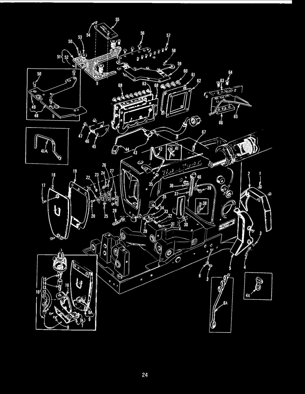
22 ILLUSTRATIONS ORDERING REPAIR PARTS This cataog has been arranged to simpify ordering repair parts. Expoded views of various sections of the mechanism are shown so that the parts may be seen in their actua position in the machine. On the page opposite the iustration wi be found a isting of the parts with their part numbers, descriptions and the numbers of pieces required in the particuar view being shown. Numbers in the first coumn are reference numbers ony and merey indicate the position of that part in the iustration. Reference numbers shoud never be used in ordering parts. Aways use the part number isted in the second coumn. Component parts of sub-assembies which can be furnished for repairs are indicated by indenting their descriptions under the description of the main sub-assemby. Exampe: AK A E C K Looper Drive Lever Crank Assemby, for Styes L, W, Casses 56300, and Bearing Cap Screw, ower Oi Spasher Ba Joint Guide Fork Bearing Cap Screw, upper It wi be noted in the above exampe that the eccentric, ba stud and bearing are not isted. The reason is that repacement of these parts individuay is not recommended, so the compete sub-assemby shoud be ordered. At the back of the book wi be found a numerica index of a the parts shown in this book. This wi faciitate ocating the iustration and description when ony the part number is known. IDENTIFYING PARTS Where the construction permits, each part is stamped with its part number. On some of the smaer parts and on those where construction does not permit, an identification etter is stamped in to distinguish the part from simiar ones. Part numbers represent the same part, regardess of cataog in which they appear. IMPORTANT! ON ALL ORDERS, PLEASE INCLUDE PART NAME AND STYLE OF MACHINE FOR WHICH PART IS ORDERED. TERMS Prices are net cash and subject to change without notice. A shipments are forwarded f.o.b. shipping point. Parce Post shipments are insured uness otherwise directed. A charge is made to cover postage and insurance. 22
23 Before this machine eft the factory it was adjusted and inspected to give you the utmost satisfaction and durabiity at a times. If, however, the machine has been readjusted and is not sewing propery, see chart beow for suggestions which may prove beneficia to you. SKIPPED STITCHES Condition Causes Cures Neede oop too sma Take-up wire set too ow Raise take-up wire sighty Neede thread stretched at bottom of stroke, oop not formed ti stretch reieved Neede thread creased because it is too tight and neede is hot Neede thread pinched by neede guard, coapsing neede oop Thread twisting around neede Neede thread sticking in neede grooves, due to heat Length of neede eye too ong, causing deay in neede oop formation Neede does not rise enough to form neede oop propery Lower frame thread eyeet and/ or reduce neede tension Use oversize ba eye neede, ower frame neede eyeet, reduce tension Drop neede guard sighty Keep neede oop as sma as possibe, keep neede thread tension to a minimum. Use a eft twist thread Use oversize ba eye neede, to reduce friction Use neede with shorter eye, drop neede bar sighty or increase ooper gauge /64 to /32 inch Increase ooper gauge /64 to /32 inch Looper misses neede oop Materia is not hed down in Use tractor type presser foot, as presser foot is coming front of seam and is fagging if avaiabe, or see if presser off a seam bar is sticking Neede oop formed propery but brushed out of the way by ooper Neede defecting toward operator Neede bar set too high Use sharp point neede Lower neede bar sighty Looper misses neede oop Neede defecting toward oper- Do not hod back excessivey on when operator is trying to ator who may be hoding back on on materia. Propery adjust match seams or ends of gar- materia whie matching seams feed and maintain a ight ments or ends of garment presser foot pressure so operator does not hod back Machine misses neede oop Neede defecting toward the Move neede guard to the rear when stitch ength is in- operator because the neede creased guard is set too far forward Neede misses triange on Looper thread too oose, not "Increase ooper thread tension ooper thread side making a good triange NOTE: Neede being defected to the Do not pu materia at the rear by burr on neede point back. Use a sharp neede to or due to operator puing on stop neede from gancing off materia, or neede gancing seam. Check neede for burr off when coming on a seam More detaied information concerning the doube ocked stitch (stitch type 40) is avaiabe under "Stitch Formation, Type 40". 23

24 56 50 i
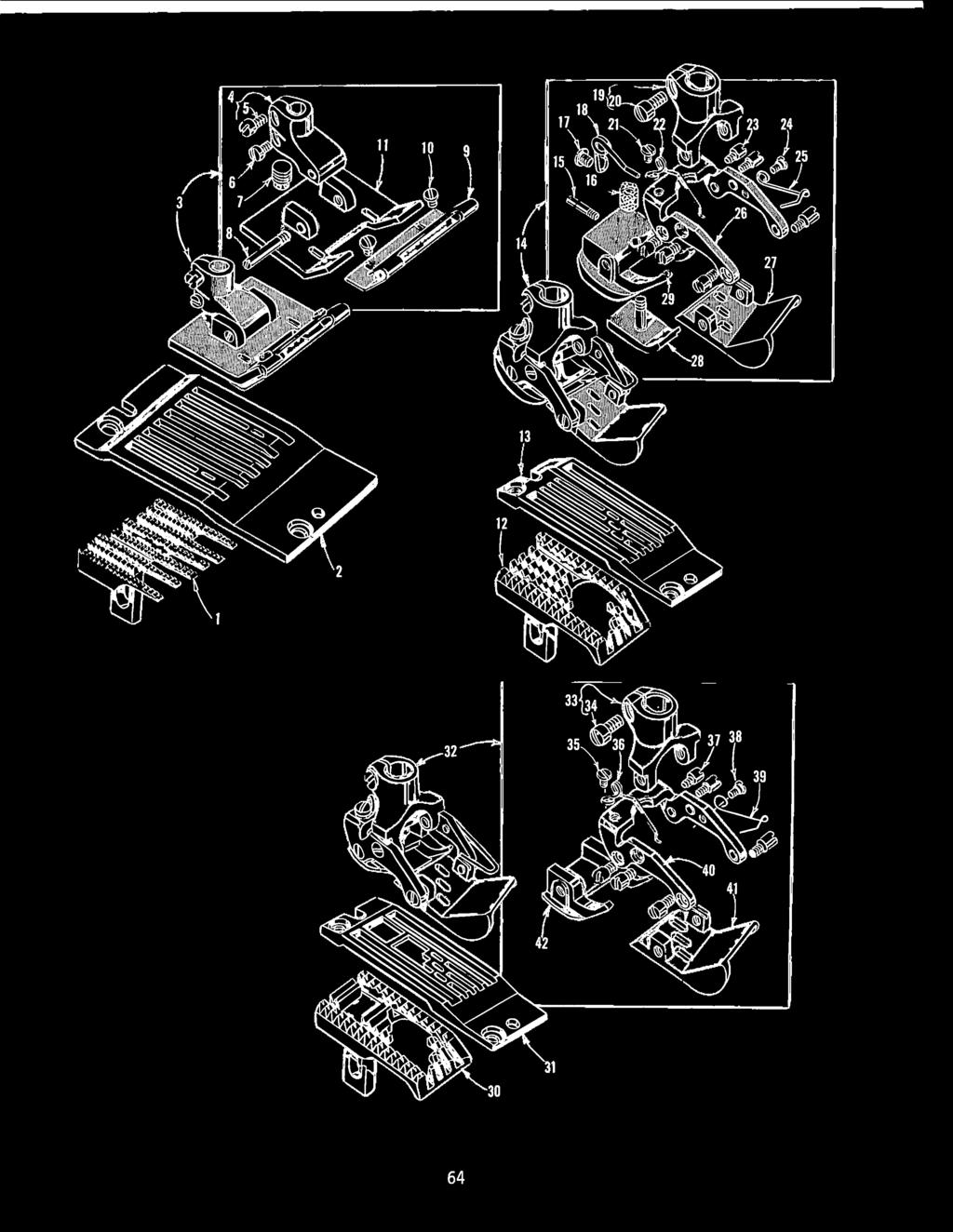
25 Ref. -!9..: A 5 6 6A 7 7A 8 9 9A *37 * A Part...!i!!..: AV 98 A 52 A 58 A G 2396 BP 2396 AG C 2396 BR 638 M AL BK C N D C 5294 R A A WD 5438 C 57 WB A A K J J J A G H D E AA AB Y E L MAIN FRAME, THROAT PLATE SUPPORTS, MISCELLANEOUS COVERS AND OILING PARTS Amt. ~~~~ ~ Screw Bet Guard Screw Looper Thread Eyeet, for a Casses except Looper Thread Eyeet, for Cass Looper Thread Guard Looper Thread Eyeet, for singe neede machines Looper Thread Eyeet, for two and three neede machines Neede Thread Lubricator, for Cass Fet Pad Screw, for Cass Head Cover, for Styes R, J, H, J, P, R Pug Screw Neede Thread Lubricator Oi Reservoir, for Cass Nut Connection Seeve Couping Adapter Oi Cup Neede Thread Lubricator Oi Reservoir Bracket, for Cass Screw, for head cover ,3 Head Cover, for a Styes except R, J, H, J, P, R Gasket Screw Head Oi Tube Camp Nut Head Oi Tube Mounting Bock Screw Screw Lockwasher Presser Bar Connection Guide Pate Frame Neede Thread Eyeet, for Stye J Screw, for Styes s, W; W, AL Screw for , for Stye J Neede Lever Eyeet Gasket Nipper Spring Screw, for Styes S, W; W, AL Nipper Spring, for Styes s, W; W, AL Nipper Spring Pate, for Styes S, W; W, AL ~ Nipper Spring Base, for Styes S, W; W, AL Pug Screw and Screw for take-up wire Adapter Pug Screw Frame Neede Thread Eyeet, for a Styes except E, F, G, N, R, U, X, AH, AL and J Frame Neede Thread Eyeet, for Stye J Screw Washer Neede Thread Take-up Wire, for Stye M, Casses 56400, 56500, 56700, and except Stye W Neede Thread Take-up Wire, for Styes E, F, G, N, R, U, X, AH, AL Neede Thread Take-up Wire, for Styes W; H, W Base Oi Pump Assemby Intake Fet Gasket Looper Drive Shaft Reservoir Cover Screw Throat Pate Support, for Styes H, K, L, W, H, M, AL and Casses , 56700, Dowe Pin Screw, for throat pate support Throat Pate Support, for Styes R, Sand Cass except Styes H, M, AL Dowe Pin We Nut Screw, for throat pate, countersunk head, for Styes R, Sand Cass except Styes H, M, AL Throat Pate (See Pages 47, 49, 5, 55, 57, 59, 6, 63, 65) Screw Screw Oi Reservoir Top Cover Gasket Screw Crank Chamber Cover, ower Gasket Oi Reservoir Back Cover Screw Oi Drip Pate Oi Drip Pate Camping Bock Screw Gasket Screw *See Page 35 for thumbscrew adjustabe frame neede thread eyeet assemby MY for Styes E, F, G, N, R, U, X, AH and AL. 25


26 24 8~20,8 G \ \ \ \ 26
27 Ref MAIN FRAME, BUSHINGS, OIL GAUGE AND MISCELLANEOUS OILING PARTS Part R D A 635 B 6256 G C B K G F E B B 2657 X H J AC C B 2254 C E M 554 E W B Bk P W AC BV Q G T L C AA B 5690 Description Amt. ~ Screw Pug Screw Nut Oi Gauge Adjusting Shaft Nut Washer Oi Retaining Ring Oi Gauge Foat Lever Assemby Oi Gauge Connecting Rod Oi Gauge "0" Ring Spring Washer Nut Bushing Housing Gasket Crankshaft Bushing Housing Screw Tension Reease Lever Shaft Bushing Thrust Washer Piot Ring Neede Thrust Bearing Neede Lever Bearing Oier and Baffe Pate Assemby- - Screw Gasket Upper Crank Chamber Cover Screw Oi Fier Pug Screw Gasket Neede Bar Bushing, upper Oi Attraction Fet Feed Rocker Shaft Bushing Fet Main Shaft Bushing, eft Looper Rocker Shaft Bushing Base Fet, front Looper Drive Lever Shaft Bushing, front Thrust Adjusting Screw Intake Fiter Base Fet, rear Main Shaft Bushing, right Head Oi Pump Assemby Intake Fet Neede Bar Bushing, ower, for a Styes except J, P, R Neede Bar Bushing, ower, for Styes J, P, R - - Presser Bar Bushing, ower Looper Drive Lever Shaft Bushing, rear Main Shaft Bushing, intermediate

 50 TORQUE TO 9-2 in.")
28 TORQUE TO 9-2 in bs ~(2"'-2 -..:;;;.2..:...;4 c:::.:;~~/.,:!jkg~) TORQUE TO in. bs. (28-30cm/kg) 50 TORQUE TO 9-2 in. bs. (22-24 cm/kg) 28
29 Ref Part Ji!!.:_ H J E AC CL AA AK 2905 AL A E C K F L C D 2934 A 5636 C LL LM LN 526 M J L 5632 D 5632 N AB P 526 N R G F E D 5250 F R A A k AF K A W D A G D A CRANKSHAFT, NEEDLE LEVER AND LOOPER DRIVING PARTS Amt. Description ~ Thrust Washer Piot Ring Neede Thrust Bearing Looper Drive Lever, marked "D" Thrust Adjusting Screw Wick Oi Looper Drive Lever Rocker Shaft "O" Ring, for puey and ooper drive ever rocker shaft Looper Drive Lever Crank Assemby, for Styes L, Wand Casses 56300, 56500, Looper Drive Lever Crank Assemby, for Styes H, K, R, Sand Casses 56400, Searing Cap Screw, ower Oi Spasher Ba Joint Guide Fork Bearing Cap Screw, upper Looper Drive Lever Couping Screw Set Screw Spot Screw Base Oi Pump, (See Ref Page 25} Head Oi Pump, (See Ref Page 27) Nut Connecting Rod Guide Crankshaft Assemby,.90 inch throw, for Styes L, Wand Cass except Styes H, M Crankshaft Assemby,.770 inch throw, for Styes H, K, R, Sand Casses 56400, Crankshaft Assemby,.990 inch throw, for Styes H, Mand Casses 56500, Neede Bearing Counterweight Screw Thrust Coar Screw Screw Retaining Pate Handwhee Puey Screw Neede Lever Connecting Rod Nut Washer Neede Lever Connecting Rod Upper Sa Joint Assemby Screw Compression Cup Temper Load Ring Neede Lever Thrust Coar Oi Sea Ring Washer Gasket Screw Neede Sar Thread Eyeet, for two neede machines Neede Bar Thread Eyeet, for three neede machines and Cass except Styes H, M, W Screw Neede Bar Thread Eyeet, for Cass and Styes H, M, W Neede Bar Eyeet Washer Neede Bar (See Page 43) Neede Camp Nut, for Casses 56200, Neede Lever Assemby Screw Neede Bar Connection Screw Link Pin Coumbia Yarn (6 strands) Retaining Ring Neede Bar Link Screw Neede Lever Bushing Neede Lever Stud Neede Lever Thread Eyeet, for two neede machines Neede Lever Thread Eyeet, for three neede machines and Cass except Styes H, M, W Screw Neede L~ver Thread Eyeet, for Cass and Styes H, M, W


30 2 TORQUE TO 9-2 in. bs. (22-24 cm/kg) 40B TORQUE TO 30


31 Ref. Part -!!!.:.. -!!!.: N L N G 6 W C067 E B A C C D E C M R M F E G Bk U J F A A D A C LV F Ref. 40A 40B 40C 40D 40E - LOOPER ROCKER AND CONNECTING ROD PARTS Amt. Description ~ Nut, for a Styes except J Washer, for a Styes except J Thrust Washer Looper Rocker Shaft Camp, for a Styes except J Looper Rocker Shaft Coar Stud, for a Styes except J Coumbia Woo Yarn (4 strands - 8 inches ong) Looper Rocker Shaft, for a Styes except J Cork Pug Looper Rocker Shaft Arm Looper Avoid Link Pin Looper Rocker Frame, for a Styes except J Stop Screw Screw Looper Rocker Stud Nut, for a Styes except J Screw Looper Rocker Frame Lock Screw Nut, for a Styes except J Looper (See Pa~e 45) Looper Coar (See Page 45) Screw ,2,3 Looper Connecting Rod Ba Joint, eft, for a Styes except J Screw Nut, eft hand thread Looper Connecting Rod, for a Styes except J and Cass Looper Connecting Rod, for Cass Nut, right hand thread Looper Drive Lever, marked "D" Screw Washer Looper Lever Stud Washer Nut Looper Connecting Rod Jointed Section Assemby, right, for a Styes except J- - - Ferrue Truarc Ring Hinge Pin Spring Spring Pin Screw Looper Connecting Rod Ba Joint Oier, eft Looper Rocker Assemby (See Chart Beow) Looper Rocker Cone Stud Looper Rocker (See Chart Beow) Looper Rocker Cone Screw Lock Nut Lock Nut Screw Looper Rocker Shaft, for Stye J Looper Rocker Frame, for Stye J Stop Screw Set Screw Spot Screw Looper Rocker Stud Nut, for Stye J Looper Rocker Shaft Thrust Washer, eft, for Stye J Nut, for Stye J Looper Rocker Spacing Pate, for 56 gauge, Stye J Looper Rocker Spacing Pate, for 64 gauge, Stye J Nut, for Stye J Looper Rocker Link, for 56 gauge, Stye J Looper Rocker Link, for 64 gauge, Stye J Looper Rocker Link Ferrue, for Stye J Screw, for Stye J Looper Connecting Rod Ba Joint, eft, for Stye J Screw Looper Connecting Rod, for Stye J Looper Connecting Rod Assemby, right, for Stye J Ferrue Ref. 40 Ref. 42 I. D. Amt. Assemby Rocker Mark For Machines Req V 5633 s Casses 56200, X 5673 V Cass W 5643 u Cass AA 5653 X Cass Y 5693 z Styes H, p A AB Styes J, R 3
 FROM B EDCA'3TING 045 INCH TORQUE T 9-2 (22-24 i;~/kbs. --=.")

32 ~- ' ' ' ' ~ 29 RIGHT HEAD T SIDE OF MAIN (.4 0 BE SET SHAFT _.:..;;.~mu.,m) FROM B EDCA'3TING 045 INCH TORQUE T 9-2 (22-24 i;~/kbs. --=.., g) //'-. <. /// / ~~~6';;, ' / / 5!J ' / 4 't--= i---~~~,taL ' s--- srr~- ' ~~ _...-,--!J TORQUE TO 55 in. bs (63cm/kgi _()_.J-nCS - () ~~ 32


33 Ref A 29 B A Part MJ E 6042 A D B C E A C C B D A 5622 A E B 2289 B NM NM NM AA N NM NM NM NM AA C D N P L C 6042 A 258 A P CB L D B G 2265 CD J A H 6434 G A MAIN SHAFT, TAKE-UPS AND FEED DRIVING PARTS Description Feed Rocker Ann and Feed Crank Link Sub-Assemby Nut Washer Locking Stud Screw, for ink pin Feed Crank Link Feed Crank Link Ferrue Feed Crank Link Pin Oi Wick Nut, eft thread Washer Screw Main Shaft Head Pate Screw Feed Crank Stud, marked "A" Quad Ring Feed Crank Stud Insert Stitch Reguating Screw Main Shaft, for a Styes except J Main Shaft, for Stye J Gasket Oi Fow Reguating Screw Feed Lift Eccentric Assemby, for Styes H,K,R,S; U,X; J and Cass Feed Lift Eccentric Assemby, for Styes L,W; A,B,C,J, U, H,J,P and except Styes H,M,U,X Feed Lift Eccentric Assemby, for Styes H,M; R; R Spot Screw Screw, for ink pin Thrust Washer, for feed bar Looper Avoid Eccentric Assemby~ for Cass Looper Avoid Eccentric Assemby, for Styes L, W, Casses and Looper Avoid Eccentric Assemby, for Styes H,K,R,S: E,F,G,N,R,U,X,AH,AL; J Looper Avoid Eccentric Assemby, for Styes W; H,M Spot Screw Screw, for ink pin Looper Thread Take-up, for Styes L,W and Casses 56300, and Looper Thread Take-up, for Styes H,K,R,S and Cass Looper Thread Take-up, for Stye J Spot Screw Set Screw Feed Bar, for a Styes except N,U,X,AH Feed Bar, for Styes N,U,X,AH feed Dog Hoder Feed Dog Hoder Adjusting Screw Feed Dog Hoder Washer Nut Feed Dog Height Adjusting Screw Screw Feed Rocker Shaft Feed Rocker Shaft Coar Screw Feed Bar Shaft Feed Rocker Screw Retaining Ring Washer Feed Bar Washer Neede Guard Adjusting Screw Neede Guard (See Page 43) Screw Screw, for neede guard Washer Screw, for feed dog Feed Dog {See Pages 47,49,5,55,57,59,6,63,65) Link Pin Amt. ~ 33

34 34
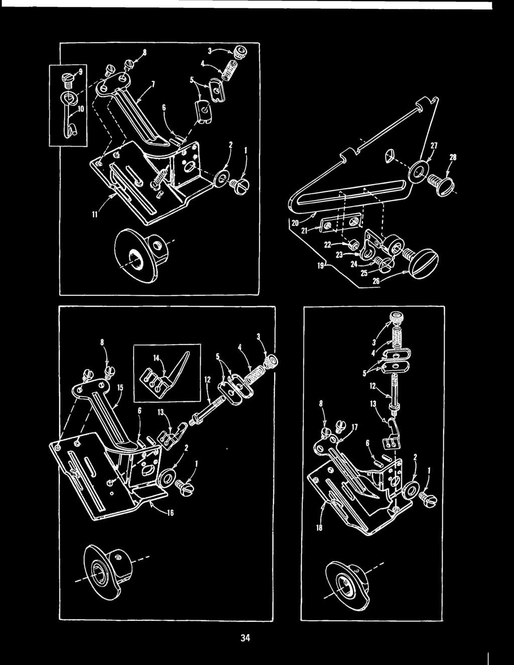
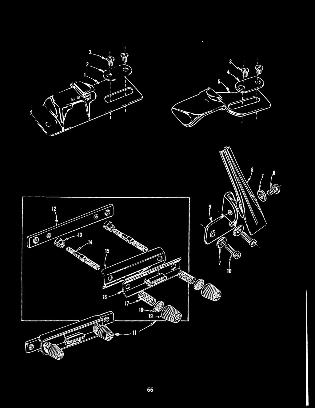
35 Ref LOOPER THREAD TAKE-UP PARTS AND THUMBSCREW ADJUSTABLE FRAME NEEDLE THREAD EYELET ASSEMBLY Part E 5959 D 5959 K 5959 B Bk A E A 5959 J A 5457 A B MY B C 58 B 98 A D Description Amt. ~ Screw ~ Washer Tension Nut Tension Spring Tension Disc Dowe Pin Cast-off Pate, for a Styes, except J- Screw, for a Styes, except E,F,G,N,R, U,X,AH,AL Screw, for Styes E,F,G,N,R,U,X,AH,AL - - Screw, for Styes E,F,G,N,R,U,X,AH,AL - - Looper Thread Guide Eyeet, for Styes E,F,G,N,R,U,X,AH,AL Take-up Shied, for Casses 56200, Tension Post, for Casses 56400, 56500, 56700, Looper Thread Guide, for Casses 56400, 56500, Looper Thread Guide, for Cass Cast-off Pate, for a Styes, except J- Take-up Shied, for Casses 56400, 56500, Cast-off Pate, for Stye J Take-up Shied, for Stye J Thumbscrew Adjustabe Frame Neede Thread Eyeet Assemby, for Styes E,F,G,N,R,U,X,AH, AL Adjusting Pate Guide Bock Guide Washer Eyeet Screw Washer Screw Washer Screw


36 r - Qm_/ 2r 'I 9 J. L_ 36
37 Ref. Part C D A E F AK Z C Ref. Part A X A Ref. Part F F F F F-2 DISC THREAD TENSION PARTS AMOUNT REQUIRED One Two Three Neede Neede Neede Description Machine Machine Machine Nut 2 Lead-in Guide 2 4 Tension Thread Eyeet 2 4 Ferrue 2 4 Tension Post 2 4 Tens ion Disc 4 8 Tension Spring Shied 2 4 Neede Thread Tension Spring (See Chart Beow) Tension Spring Ferrue 2 Tension Nut 2 I : I Looper Thread Tension Spring (See Chart Beow) Screw Washer 2 I - I Description Amt. Req. Tension Disc Separator, for Singe neede machine Styes E, F, G, N, R, U, X, AH; Two and Three neede machines Tension Post Support, for Three neede machines Tension Post Support, for Singe neede machine Styes E, F, G, N, R, U, X, AH and Two neede machines Tension Disc Separator, for Singe neede machine Styes H, K, L, R, S, W, H, M, W, AL Tension Post Support, for Singe neede machine Styes H, K, L, R, S, W, H, M, W, AL Fet Washer, for auxiiary tension post support as required Auxiiary Tension Post Support, for Singe neede machine Styes E, F, G, N, R, U, X, AH; Two and Three neede machines- - - TENSION SPRING CHART Amt. Description Machine Stye Req. Neede Thread Tension Spring H, K, R, S D,P,R,S,T,W,X; J 2 Neede Thread Tension Spring L; E, F, G, M, N, R, U, W, X, AH, AL A, B, C, J, R, u, H, J, P. R 3 Neede Thread Tension Spring W, H Looper Thread Tension Spring H, K, R, s D, P, R, S, T, W, X; J 2 Looper Thread Tension Spring L, W, E, F, G, H, M, N, R, U, W, X, AH, AL A, B, C, J, R, U H, J, P, R 3 37


38 5 I I 24 L_ t\ ~ 30 ~ 38


39 Ref. Part 2657 W Y H C N A C F M C G D AA AB A C A E K D 3 C067 D TENSION AND LIFTER LEVER PARTS Amt. Description ~ Tension Reease and Lifter Lever Shaft Tension Reease and Lifter Lever Shaft Connection Screw Screw Lifter Lever Oi Sea Ring Washer Lifter Lever Connection Screw Presser Bar Connection and Guide, for Styes F, R- - Screw Nut Screw Screw Presser Bar Connection and Guide, for a Styes except F, R Screw Screw Screw Lifter Lever Be Crank Spring Lifter Lever Be Crank Lifter Lever Connecting Rod Presser Spring Reguator, for a styes except R- - Presser Spring Reguator, for Stye R Presser Spring, for Styes H, K, R, S, U, X- - Lifter Lever Link Screw Presser Bar, for Styes J, P Presser Spring, for Styes L, W, E, F, G, H, M, N, R, W, AH, AL and Casses 56400, 56500, 56700, Presser Bar, marked A, for a Styes except J, P, R Presser Foot (See Pages 47, 49, 5, 53, 55, 57, 59, 6, 63, 65) Presser Bar, for Stye R Cork


40 ~-Ii r ~I,--.,!, ' ' _, ' i"--2e 29 3B 40


41 Ref. ~ 2 3 3A 3B 3C OA OB OC Part C E AC B H A C C A B Y B T E BG-5/ BG-3/ BG-7/ T AC AB-3/ AB-7/ AB AB- / AB- /4 25 C V A A 25 TB 2657 E 24 S CLOTH PLATES, CLOTH PLATE COVERS, EDGE GUIDES ANO BINDERS Description Amt. ~ Screw, for edge guide Edge Guide, for Styes H, S, A, B, C, U and Cass except H, M Coth Pate Cover, 3 5/6 inches wide, for Styes F, R, X, AH Coth Pate Cover, 3 5/32 inches wide, for Styes R, S, E, G, N, U, W Coth Pate Cover, 3 5/64 inches wide, for Styes H, AL, and Casses 56400, 56500, except R, S Coth Pate Cover, 3 5/64 inches wide, for Styes H, K, L, M Coth Pate Cover, 3 5/64 inches wide, for Stye I~ Coth Pate Cover, 2 59/64 inches wide, for Styes R, S-48, J Coth Pate Cover Spring Screw Spring Washer Screw Screw, for coth pate Screw, for coth pate Coth Pate, for Styes R,S, E, F, G, R, W Coth Pate, for Styes N, U, X, AH Coth Pate, for Styes H, K, L, W, H, M, AL and Casses 56400, 56500, except R, S Coth Pate, for Styes R, S-48, J Body Fabric Lead-in Patfonn, for Styes Land M Binder Swinging Bracket, for Styes Land M Screw, for binder Binder Swinging Bracket Support, for Styes Land M - - Camping Pate, for Styes Land M Screw, for binder swinging bracket support Spring Washer, for binder swinging bracket Screw, for binder swinging bracket Engish Binder, uses sevage edge binding strip 5/8 inch wide, 5/32 inches capacity for body fabric, finsihes 5/6 inch wide, for Styes Land M Engish Binder, use 3/4 inch strip and finishes 3/8 inch, for Styes Land M Engish Binder, uses 7/8 inch strip and finishes 7/6 inch, for Styes Land M Screw, for binder support Camping Pate, for Stye K Binder Support, for Stye K Screw, for binder Cut Edge Binder, uses strip cut 3/4 inch wide, finishes 7/32 inch wide, for Stye K Cut Edge Binder, uses strip cut 7/8 inch wide, finishes /4 inch wide, for Stye K Cut Edge Binder, uses strip cut inch wide, finishes 9/32 inch wide, for Stye K Cut Edge Binder, uses strip cut /8 inch wide, finishes /32 inch wide, for Stye K Cut Edge Binder, uses strip cut /4 inch wide, finishes 3/32 inch wide, for Stye K Screw, for body fabric ead-in patfonn Washer Pate, for Stye K Body Fabric Lead-in Patfonn, for Stye K Screw, for pin tension Pin Tension, for binding on Styes K, Land M - - Screw, for edge guide Washer, for edge guide Edge Guide, for Stye W
42 2& ~24 ~ ~ 42
43 Ref A Part 527 C C C C C C C-8 50 J D 50 J K K B D B-6 50 J B-8 50 J E B M N D E- 50 J G- 558 C B B C L C- 50 J C A A A P B B B 605 A J N N A 50 J NEEDLE BARS, NEEDLE HOLDERS AND NEEDLE GUARDS Description Neede Bar, marked "CU", for Casses 56200, Neede Camp Nut, for Casses 56200, Neede Guard, for Casses 56200, Screw _ _ Neede Bar, marked "CV-6", for 6 gauge, Stye P - Neede Bar, marked "CV-8", for 8 gauge, Styes P, T, W Neede Bar, marked "CV-0", for 0 gauge, Styes P, T, W, Neede Bar, marked "CV-2", for 2 gauge, Styes D, P, T, W - Neede Bar, marked "CV-6", for 6 gauge, Styes D, P, T, W - - Neede Bar, marked "CV-8", for 8 gauge, Stye P - Stop Pin Screw, for neede Amt. ~ Neede Hoder, marked "D-6", for a gauges Styes D, P, T, Wand 6 gauge, Stye J Spot Screw Neede Guard, for Cass 56400, a gauges Neede Bar, marked "DE", for Nos. 24, 26, 32, 48 gauges, Styes R, S, X Stop Pin Neede Hoder, marked "L-24", for No, 24 gauge, Stye X - - Neede Hoder, marked "L-26", for 26 gauge, Stye X - - Neede Hoder, marked "D-32", for 32 gauge, Stye S - - Neede Hoder, marked "AC-48", for 48 gauge, Styes R, S Neede Bar, marked "ET", for 6 gauge, Stye J Stop Pin Neede Hoder, marked "D-6", for 6 gauge, Stye J and a gauges Stye D, P, T, W Neede Bar, marked "EU", for 8 gauge, Stye J, R - Stop Pin Neede Hoder, marked "G-5", for 8 gauge, Styes J, R Thread Guide Screw Neede Guard, for Styes J, Ra gauges Neede Bar Assemby, for 7 S. P.I., Styes B, U Neede Bar Assemby, for 0 S.P.I., Stye C Neede Bar, marked "EK", for 7 S. P. I., Styes B, U Neede Bar, marked "EL", for 0 S.P. I., Stye C - - Stop Pin Neede Hoder, marked "P-", for 7 S.P. I., Styes B, U Neede Hoder, marked "Q-", for 0 S.P.I., Stye C - Spot Screw Screw, for neede Screw, for neede Neede Guard, for 7 S.P.I., Styes B, U Neede Guard, for 0 S.P.I., Stye C - - Neede Bar Assemby, for 5 S.P.I., Stye A - - Neede Bar, marked "ES", for 5 S. P. I., Stye A Stop Pin Neede Hoder, marked "AS", for 5 S.P.I., Stye A - Spot Screw Screw, for neede - Screw, for neede Neede Guard, for 5 S.P.I., Stye A - Neede Bar, marked "AU", for Stye J a gauges Neede Hoder, marked "AB-56", for 56 gauge, Stye J Neede Hoder, marked "AB-64", for 64 gauge, Stye J Spot Screw Screw, for neede Neede Stop and Thread Eyeet, for 64 gauge 2 Neede Stop and Thread Eyeet, for 56 gauge - Screw, for 64 gauge Screw, for 56 gauge Neede Guard, for Stye J a gauges Neede Bar, marked "EP-9", for Nos. 8, 9 gauges, Styes H, J, P, R- - - Stop Pin Neede Hoder, marked "C-8", for 8 gauge, Stye H Neede Hoder, marked "C-9", for 9 gauge, Styes H, J, P, R Screw, for center neede Screw, for neede Neede Guard, for Cass a gauges Neede Bar, marked "DC", for No, 7 gauge, Stye H - - Stop Pin Neede Hoder, marked "E-7", for 7 gauge, Stye H
44 A...~ ~
45 Ref. Part 5409 C * * * * C G C H C 5909 C M M D D D C B B B A D B W A *Not shown on picture pate. LOOPER, LOOPER COLLARS AND LOOPER NEEDLE GUARDS Amt. Description ~ Looper, for Stye Land Cass except Styes H, M, AL Looper, for Styes K, R Looper, back, for Cass a gauges, Styes R, S Looper, front, for 6 gauge, Stye P Looper, front, for 8 gauge, Styes P, T, W Looper, front, for 0 gauge, Styes P, T, W Looper, front, for 2 gauge, Styes D, P, T, W- - Looper, front, for 6 gauge, Styes D, P, T, W- - Looper, front, for 8 gauge, Stye P Looper, front, for 24 gauge, Stye X Looper, front, for 26 gauge, Stye X Looper, front, for 32 gauge, Stye S Looper, front, for 48 gauge, Styes R, S- - Looper, back, for Styes A, B, C, U Looper, front, for 7 S.P.I., Styes B, U Looper, front, for 0 S.P.I., Stye C Looper, front, for 5 S.P.I., Stye A Looper, for Stye M Looper, back, for Styes J, R Looper, front, for 6 gauge, Stye J- - - Looper, front, for 8 gauge, Styes J, R- - Looper, eft, for Stye J a gauges Looper, right, for Stye J a gauges Looper, back, for 9 gauge, Styes H, J, P, R- - - Looper, back, for 8 gauge, Stye H Looper, back, for 7 gauge, Stye H Looper, for Stye M, midde ooper for Cass and back ooper for Styes J, R Looper, front, for 9 gauge, Styes H, J, P, R - - Looper, front, for 8 gauge, Stye H Looper, front, for 7 gauge, Stye H Looper Coar, for Styes H, K, R, Sand Cass except Styes G, H, M Looper Coar, for Styes L, W, H, M, J -,2 Screw, for ooper ,2,3 Looper, for Stye H Looper, for Styes H, S Looper, back, for Styes R, S Looper, for Styes W, AL- - Looper Neede Guard, for Stye W- - Screw, for ooper neede guard
46 46

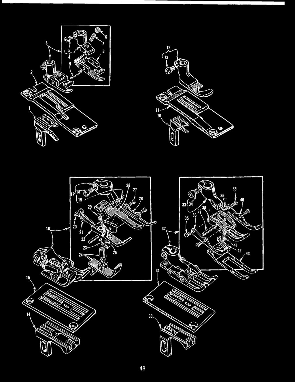
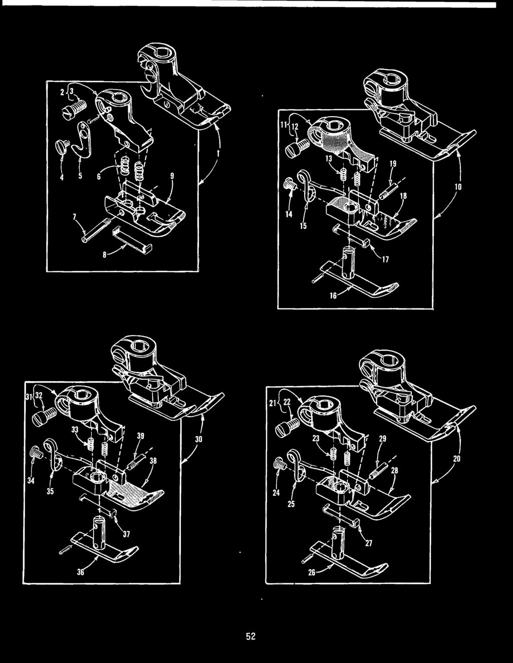
47 Ref FEED DOGS, THROAT PLATES, PRESSER FEET AND TOP GRIP-FEED DRIVING PARTS Part 9205 E 9224 E AL AL 5205 R H 5320 M 5330 AJ 9 87 B 74 B 5330 AH 5330 W 5330 AG 5334 A 5334 D G J C S K Z A 5330 AB F G AD 5330 AE E 5324 F U 5330 M A 5330 R E 5330 N 6430 BT F 5330 P * 87 U *5330 S *56334 F Description Feed Dog, 6 teeth per inch, for Styes G, U Throat Pate, for Styes G, W Feed Dog, 2 teeth per inch, for Stye AL Throat Pate, for Stye AL Feed Dog, 6 teeth per inch, for Stye H Throat Pate, for Stye H Presser Foot, for Styes H, G, AL Presser Foot Shank Screw Screw Chain Cutting Knife Yieding Section Spring Presser Foot Bottom Top Grip Feed Presser Foot Driving Arm, for Styes N, U, X, AH Presser Foot Connecting Rod, for Styes N, U, X, AH Screw Screw, for top grip feed presser foot driving arm Screw Connecting Rod Fat Spring, for Styes N, U, X, AH Screw Chain Cutting Knife, for Styes N, U, X, AH Feed Dog, 6 teeth per inch, for Stye X Throat Pate, for Stye X Presser Foot, for Stye X Presser Foot Shank Screw Screw Screw Screw Spring Presser Foot Yieding Section Yieding Section Spring Presser Foot Bottom, marked AG Presser Foot Feeding Section, 6 teeth per inch Feed Section Guide Screw Feed Dog, 6 teeth per inch, for Styes G, U Throat Pate, for Styes N, U Presser Foot, for Stye U Presser Foot Shank Screw Screw Screw Hinge Pin Feed Section Guide, right Presser Foot Bottom Presser Foot Feeding Section, 6 teeth per inch Spring Yieding Section Feed Section Guide, eft Screw, for connecting rod hinge Chain Cutting Knife Connecting Rod Hinge * Not Shown on picture pate, but are components of part Nos and U, Ref. 25 and 4 respectivey. 47 Amt. ~

48 2 48


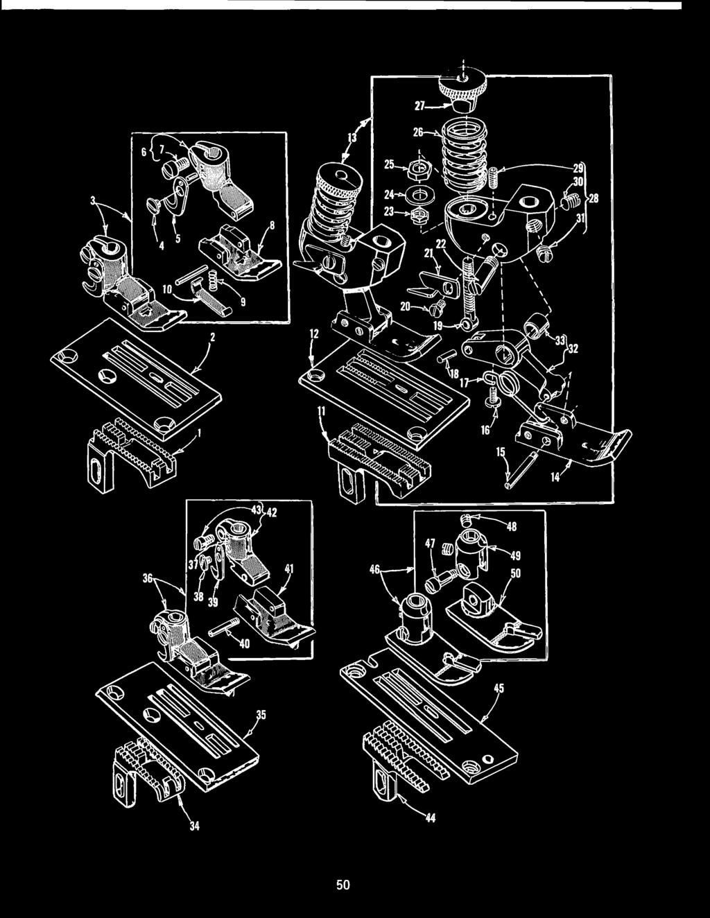
49 Ref. Part 6405 M B W F A A E A 5224 A A W W W Z A F AB G AE BB A F A M P A E R BT F AX FEED DOGS, THROAT PLATES, PRESSER FEET Amt. Description ~ Feed Dog, 2 teeth per inch, for Styes Land M Throat Pate, for Styes Land M Presser Foot, for Styes Land M Presser Foot Shank Camp Screw Adjusting Nut Adjusting Screw Presser Foot Bottom Hinge Screw Feed Dog, 6 teeth per inch, for Stye K Throat Pate, for Stye K Presser Foot, for Stye K Camp Screw Feed Dog, 22 teeth per inch, for Stye AH Throat Pate, for Stye AH Presser Foot, for Stye AH Presser Foot Shank Screw Screw Screw Spring Presser Foot Bottom, marked AG Yieding Section Presser Foot Yieding Section Spring Feeding Section Guide Screw Presser Foot Feeding Section, 22 teeth per inch- - - Screw Feed Dog, 22 teeth per inch, for Stye N Throat Pate, for Styes N, U Presser Foot, for Stye N Presser Foot Shank Screw Screw Feed Section Guide, eft Hinge Pin Presser Foot Bottom Screw Feed Section Guide, right Spring Yieding Section Presser Foot Feeding Section, 22 teeth per inch - - From the ibrary of: Superior 49 Sewing Machine & Suppy LLC

50 34 50


51 FEED DOGS, THROAT PLATES, PRESSER FEET Ref. Part Description Arnt. Req N 87 B 74 B 5330 AK AL 5330 W 5330 AM 5305 W 5324 W F AB B 73 A AX AJ AG AC AF 5430 F AU 407 G AD AH AK B AE AP 5305 U 9224 E 5320 J 74 A 87 A 74 B B 5330 X 5330 Y B 5324 B 5320 B 86 X XD 5330 B Feed Dog, 6 teeth per inch, for Stye S Throat Pate, for Stye S- - Presser Foot, bottom marked "5330 AL" for Stye S Screw, for chain cutting knife Chain Cutting Knife Shank Camp Screw - - Presser Foot Bottom Spring Yieding Section Feed Dog, 22 teeth per inch, for Styes F, R, AH - Throat Pate, for Styes F, R, AH Presser Foot, for Stye F Presser Foot Bottom, marked "BS" - Hinge Screw Screw, for titing spring Titing Spring Hinge Pin Connecting Screw Screw, for chain cutting knife Chain Cutting Knife, marked "D" Hinge Screw Nut Washer Locking Nut Compression Spring Pressure Reguating Nut Yoke Screw Screw Screw Pr,esser Foot Link, marked "A" Bushing Feed Dog, 2 teeth per inch, for Stye W - - Throat Pate, for Styes G and W - Presser Foot, for Stye W Pin, for chain cutting knife - Screw, for chain cutting knife Chain Cutting Knife Hinge Screw Presser Foot Bottom Presser Foot Shank Camp Screw - - Feed Dog, 2 teeth per inch, for Stye H - Throat Pate, for Stye H Presser Foot, for Stye H Hinge Screw Set Screw Presser Foot Shank - - Presser Foot Bottom

52 52


53 Ref. Part * G P A 5 74 B T B S R * B U BT A Y AA W G * C U BT A Y AA X G * D U BT A V AA W G PRESSER FEET Description * Avaiabe as an extra send and charge item. Amt. ~ Presser Foot, bottom marked BM - - Presser Foot Shank Camp Screw Screw Chain Cutting Knife Spring Hinge Screw Yieding Section Presser Foot Bottom, marked Bfv - - Presser Foot Presser Foot Shank Camp Screw Spring Screw Spring Yeding Section Yieding Section Presser Foot Bottom Hinge Screw Presser Foot Presser Foot Shank - - Camp Screw Spring Screw Spring Yieding Section Yieding Section Presser Foot Bottom Hinge Screw Presser Foot Presser Foot Shank Camp Screw Spring Screw Spring Yieding Section Yieding Section Presser Foot Bottom Hinge Screw

54 8 54
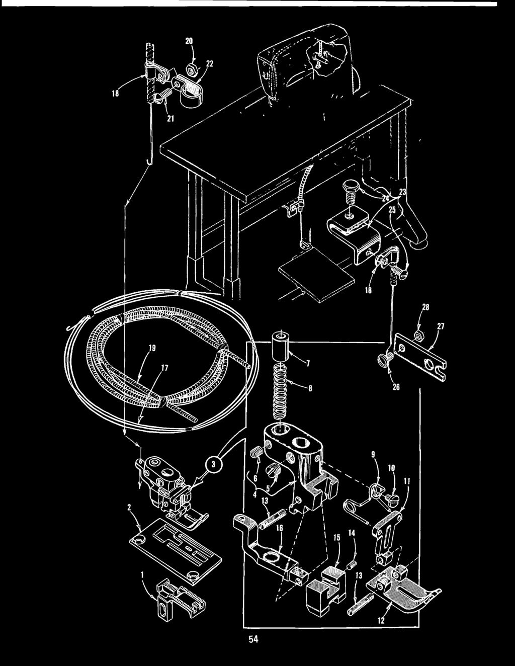
55 Ref AUTOMATIC CHAIN CUTTER AND PRESSURE RELEASE ATTACHMENT FOR STYLE E Part 5305 V 5324 V A H 88 HA73 B N J 6430 AJ 73 A M L R HA73 B 6430 AN K 5330 BC BO NU-2 SC BF SC-2 SC A 5330 BE 2934 A Amt. Description ~ Feed Dog, marked BN, 22 teeth per inch Throat Pate Presser Foot, bottom marked "AU" Presser Foot Shank Screw, for presser foot shank Screw, for spring adjusting pin Spring Adjusting Pin Chain Cutter Spring Spring, for presser foot bottom Screw, for spring Yieding Section, marked "AS" - Presser Foot Bottom, marked AU Hinge Screw Screw, for chain cutter Chain Cutter, marked G Adjusting Side Chain Cutter Reease Cabe Stationary Cabe Camp Chain Cutter Reease Cabe Casing Nut Screw Presser Bar Bushing Camp Stationary Cabe Camp Screw Screw Screw Peda Connection Nut, for cabe adjusting screw NOTE: Automatic Chain Cutting Reease Attachment Kit GJ, consists of Ref. Nos. 7 thru 28 incusive. 2 55

56 56
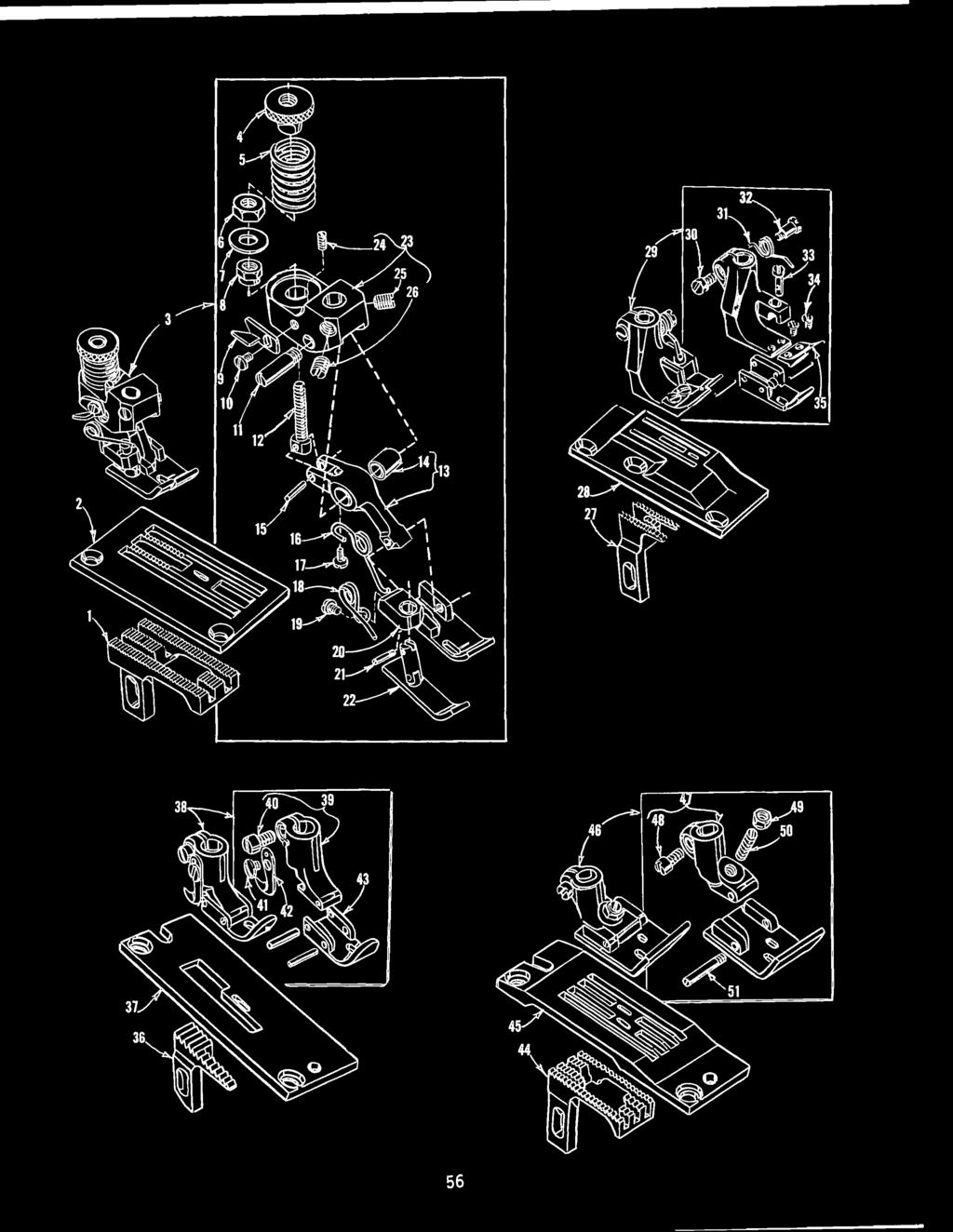
57 Ref Part 5305 W 5324 W H AH AD 407 G AU 5430 F AC AF AG AN AP AJ AX 73 A AR AL G AM AK B WD 9634 A W A 5220 W 5230 F 9 87 B 74 B 5230 G 5405 AD AD AD AD AD AG-4½ 5430 D F A E FEED DOGS, THROAT PLATES, PRESSER FEET Description Amt. ~ Feed Dog, 22 teeth per inch, for Styes F, R, AH Throat Pate, for Styes F, R, AH Presser Foot, for Stye R Pressure Reguating Nut Compression Spring Locking Nut Washer Nut Chain Cutting Knife, marked "D" Screw, for chain cutting knife Hinge Screw Connecting Screw Presser Foot Link, marked "B" Bushing Hinge Pin Titing Spring Screw, for titing spring Spring, for yieding section Screw, for yieding section spring Presser Foot Bottom, marked "BR" Hinge Screw Yieding Section Yoke Screw Screw Screw ~ Feed Dog, 6 teeth per inch, for Stye R Throat Pate, for Stye R Presser Foot, for Stye R Camp Screw Yieding Section Spring Screw, for yieding section spring Spring Pin Screw, for detachabe toe Detachabe Toe Feed Dog, 2 teeth per inch, for Stye W Throat Pate, for Stye W Presser Foot, for Stye W Presser Foot Shank Camp Screw Screw, for chain cutting knife Chain Cutting Knife Presser Foot Bottom Feed Dog, 6 teeth per inch, for 2 gauge, Stye D Feed Dog, 6 teeth per inch, for 6 gauge, Stye D Throat Pate, for 2 gauge, Stye D Throat Pate, for 6 gauge, Stye D Presser Foot, for 2 gauge, Stye D Presser Foot, for 6 gauge, Stye D Presser Foot Shank Camp Screw Nut Adjusting Screw Hinge Screw

58 ,,-:+J
59 Ref Part 5405 A A A A A A D B 5430 A A A A A 5430 F D B 5430 A A A 5430 F C B A B C D E 5530 G 5530.F A 9 A AC FEED DOGS, THROAT PLATES, PRESSER FEET Description Amt. ~ Feed Dog, 6 teeth per inch, for Nos. 6 and 8 gauges, Stye P Feed Dog, 6 teeth per inch, for Nos. 0 and 2 gauges, Stye P Throat Pate, for 6 gauge, Stye P Throat Pate, for 8 gauge, Stye P Throat Pate, for 0 gauge, Stye P Throat Pate, for 2 gauge, Stye P Presser Foot, for 6 gauge, Stye P Presser Foot, for 8 gauge, Stye P Presser Foot, for 2 gauge, Stye P Presser Foot Shank Screw Hinge Screw Presser Foot Bottom, for presser foot Presser Foot Bottom, for presser foot Presser Foot Bottom, for presser foot Presser Foot Bottom, for presser foot Adjusting Screw Adjusting Nut Feed Dog, 6 teeth per inch, for Nos. 6 and 8 gauges, Stye P Throat Pate, for 6 gauge, Stye P Throat Pate, for 8 gauge, Stye P Presser Foot, for 6 gauge, Stye P Presser Foot, for 8 gauge, Stye P Presser Foot Shank Screw Hinge Screw Presser Foot Bottom, for presser foot Presser Foot Bottom, for presser foot Adjusting Screw Adjusting Nut Feed Dog, 2 teeth per inch, for Nos. 6 and 8 gauges, Stye J Throat Pate, for 6 gauge, Stye J Throat Pate, for 8 gauge, Stye J Presser Foot, for 6 gauge, Stye J Presser Foot, for 8 gauge, Stye J Presser Foot Shank Screw Spring Hinge Pin Presser Foot Bottom, for presser foot Presser Foot Bottom, for presser foot Feed Dog, 0 teeth per inch, for 7 and 0 S.P.I., Styes B, C Feed Dog, 0 teeth per inch, for 5 S.P.I., Stye A Throat Pate, for 5 S.P.I., Stye A Throat Pate, for 7 S.P.I., Stye B Throat Pate, for 0 S.P.I., Stye C Insert Presser Foot, a stitches per inch, Styes A, B, C, U - - Presser Foot Shank Screw Hinge Screw Spring Punger Yieding Section Screw Chain Cutting Knife, Marked "D" Presser Foot Bottom Pin
60 60
61 Ref Part 5405 B B B B C C C C D B C C K K K K K K K B 9 87 A E B 5505 BR BR BR BR C AC G 5530 J AD 9 73 A AE A B D E 5530 G 5530 F A 9 A AC FEED DOGS, THROAT PLATES, PRESSER FEET Amt. Description ~ Feed Dog, 6 teeth per inch, for 32 gauge, Stye S Feed Dog, 6 teeth per inch, for 48 gauge, Stye S Throat Pate, for 32 gauge, Stye S Throat Pate, for 48 gauge, Stye S Presser Foot, for Mo. 32 gauge, Stye S Presser Foot, for 48 gauge, Styes R, S Presser Foot Bottom, for to C-32 presser foot Presser Foot Bottom, for 5420 C-48 presser foot Hinge Screw Adjusting Screw Camp Screw, ower Presser Foot Shank Camp Screw, upper Feed Dog, 6 teeth per inch, for 48 gauge, Stye R Throat Pate, for 48 gauge, Stye R Feed Dog, 6 teeth per inch, for Nos. 24 and 26 gauge, Stye X Throat Pate, for to. 24 gauge, Stye X- - - Throat Pate, for tic. 26 gauge, Stye X Presser Foot, for 24 gauge,.stye X Presser Foot, for Mo. 26 gauge, Stye X Presser Foot Bottom, for Mo K-24 presser foot Presser Foot Bottom, for 5420 K-26 presser foot Presser Foot Shank Camp Screw Screw, for guide Guide Hinge Screw Feed Dog, 2 teeth per inch, for 8 gauge, Stye R Throat Pate, for 8 gauge, Stye R Presser Foot, for 8 gauge, Stye R Presser Foot Bottom, front section Hinge Screw Hinged Section Hinge Screw Presser Foot Bottom, rear section Presser Foot Shank Camp Screw Screw, for spring Spring Feed Dog, 22 teeth per inch, for gauge, Stye U Throat Pate, for gauge, Stye U Insert Presser Foot, for gauge, Styes A, B, C, U Presser Foot Shank Camp Screw Hinge Screw Spring Punger Yieding Section Screw, for chain cutting knife Chain Cutting Knife, marked "D" Presser Foot Bottom Pin


62 62


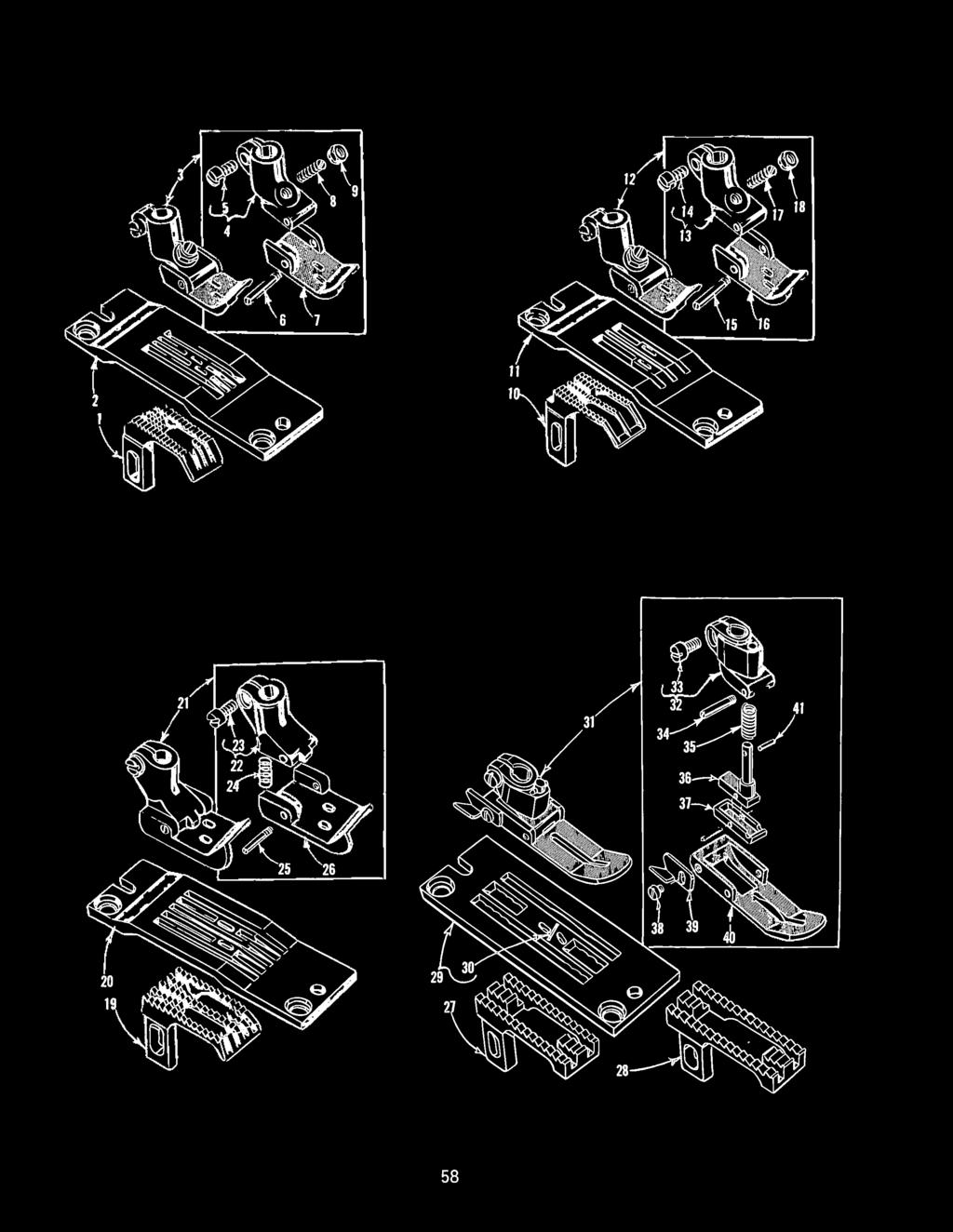
63 Ref Part 5405 R R R R R R R R R R AD AB G AC E 5430 R R R R AE 73 A 5405 G G E E E E E E E E D B 5430 E E E E A 5430 F 5905 A A A A B P P C P P-9 FEED DOGS. THROAT PLATES. PRESSER FEET Amt. Description ~ Feed Dog. 6 teeth per inch. for Nos. 8 and 0 gauges, Stye W Feed Dog. 6 teeth per inch. for Nos. 2 and 6 gauges, Stye W Throat Pate. for 8 gauge. for Stye W - Throat Pate. for 0 gauge, for Stye W Throat Pate, for 2 gauge. for Stye W Throat Pate, for 6 gauge, for Stye W Presser Foot. for 8 gauge, for Stye W Presser Foot, for 0 gauge, for Stye W Presser Foot, for 2 gauge, for Stye W Presser Foot, for 6 gauge, for Stye W Shank Camp Screw Bottom, rear section Hinge Screw, for bottom, rear section Hinged Section Hinge Screw, for bottom, front section Bottom, front section, for 5420 R-8 presser foot - - Bottom, front section, for 5420 R-0 presser foot - - Bottom, front section, for 5420 R-2 presser foot - - Bottom, front section, for 5420 R-6 presser foot - - Spring Screw Feed Dog, 22 teeth per.inch, for Nos. 8, 0 and 2 gauges, Stye T Feed dog, 22 teeth per inch for 6 gauge. Stye T- - Throat Pate, for 8 gauge, for Stye T Throat Pate, for 0 gauge, for Stye T Throat Pate, for 2 gauge, for Stye T Throat Pate, for 6 gauge, for Stye T Presser Foot, for 8 gauge, for Stye T Presser Foot, for 0 gauge, for Stye T Presser Foot, for 2 gauge, for Stye T Presser Foot, for 6 gauge. for Stye T Shank Camp Screw Hinge Screw Presser Foot Bottom, for 5420 E-8 presser foot Presser Foot Bottom, for 5420 E-0 presser foot Presser Foot Bottom, for 5420 E-2 presser foot Presser Foot Bottom, for 5420 E-6 presser foot Screw, for adjusting tit of presser foot Nut Feed Dog, 6 teeth per inch, for 7 gauge, Stye H - Throat Pate, for 7 gauge, for Stye H Presser Foot, for 7 gauge, for Stye H Presser Foot Shank Camp Screw Adjusting Screw Presser Foot Bottom Hinge Screw Feed Dog. 0 teeth per inch, for Nos. 8 and 9 gauges, Stye H Throat Pate, for 8 gauge, for Stye H Throat Pate, for 9 gauge. for Stye H Presser Foot, for 8 gauge, for Stye H Presser Foot, for 9 gauge, for Stye H Presser Foot Shank Camp Screw Spring Hinge Screw Presser Foot Bottom, for P-8 presser foot Presser Foot Bottom, for P-9 presser foot

64 64
65 Ref Part B D 5730 A A-56 9 A E E S L F 2256 D D B 9 D 73 A H A K C S AE J A A A B 9 D 73 A H A K C R FEED DOGS, THROAT PLATES, PRESSER FEET Amt. Description ~ Feed Dog, 6 teeth per inch, for 64 gauge, Stye J Feed Dog, 6 teeth per inch, for 56 gauge, Stye J Throat Pate, for 64 gauge, Stye J- - - Throat Pate, for 56 gauge, Stye J- - - Presser Foot, for 64 gauge, Stye J- - - Presser Foot, for 56 gauge, Stye J- - - Presser Foot Shank Screw Camp Screw, ower Adjusting Screw Hinge Screw Fexibe Toe, for presser foot - Fexibe Toe, for presser foot - Screw Presser Foot Bottom, for presser foot Presser Foot Bottom, for presser foot Feed Dog, 0 teeth per inch, for 9 gauge, Stye R Throat Pate, for 9 gauge, Stye R Presser Foot, for 9 gauge, Stye R Hinge Screw Adjusting Nut Screw Spring Presser Foot Shank Screw Screw Spring Screw Screw Spring Yoke Presser Foot Bottom, front section Yieding Section Presser Foot Bottom, rear section Feed Dog, 0 teeth per inch, for 9 gauge, Styes J, P Throat Pate, for 9 gauge, Styes J, P - Presser Foot, for 9 gauge, Styes J, P - Presser Foot Shank Screw Screw Spring Screw Screw Spring Yoke Presser Foot Bottom, front section Presser Foot Bottom, rear section

66 I I ' 66
67 Ref Part V 25 C V J N 282 P 26 B E 282 L 282 K AK Z ATTACHMENTS, BRACKETS AND STRIP TENSION Description Doube Edge Foder and Guide, 3/64 inch capacity, 3/6 inch overap, for Styes R Washer Pate Screw, for attachment Washer Pate Amt. ~ Body Foder, for turning body of garment downwardy, /32 inch capacity, 5/6 inch fod, for Stye S Screw, for facing strip foder Washer Facing Strip Foder, for shirt front operations, /32 inch capacity, uses strip inch wide, finishes 5/8 inch, for 32 gauge, Stye S Facing Strip Foder, for shirt front operations, /32 inch capacity, uses strip /4 inch wide, finishes 7/8 inch, for 48 gauge, Stye S Foder Bracket, for Stye S Screw, for foder bracket Strip Tension, for Stye S Strip Tension Base Tension Post Ferrue Tension Post Strip Tension Pate, inner Strip Tension Pate, outer Tension Spring Tension Nut Ferrue Tension Nut


68 3 68
69 Ref..J:!Q..,_ + - * 2 * 3 * 4 5 * 6 * 7 * 8 * 9 *0 * * Part 2340 K K K-48 K P N A Y 25 T Q A 25 cc 25 S C L V V V 235 A C 20 A D A SC F E Assemby Ref U-6-/ U-8-/ U-0-/ U-2-/ U-6-/ U-6-3/ U-8-/ U-8-3/ U-8- / U-26-/ V-8-/ V-0-/ V-2-/ V-6-/32 - ATTACHMENTS, TAPE REEL AND MISCELLANEOUS ACCESSORIES Description Center Pait Foder, /32 inch capacity pait extends /4 inch beyond rows of stitches, uses pait cut 2 /2 inches wide, finishes /2 inches; interining strip cut 5/32 inches wide, for 64 gauge, for Styes J Center Pait Foder, /32 inch capacity, pait extends /4 inch beyond rows of stitches, uses pait cut 2 3/8 inches wide, finishes 3/8 inches; interining strip cut /32 inches wide, for 56 gauge, for Stye J Center Pait Foder, /32 inch capacity, pait extends /4 inch beyond rows of stitches, uses pait cut 2 /4 inches wide, finishes /4 inches; interining strip cut 7/32 inches wide, for 48 gauge, for Stye R Center Pait Foder, /6 inch capacity, pait extends /4 inch beyond rows of stitches, uses pait cut 2 /2 inches wide, finishes /2 inches; interining strip cut 7/6 inches wide, for 64 gauge, for Stye J Screw Foder Bracket, for Styes R, J Foder Swinging Ann, for Styes R, J Screw Screw Foder Swinging Ann Support, for Styes R, J Screw Foder Camp, for Styes R, J Adjusting Screw Screw Screw Screw Anguar Interining Guide, reversibe, for 64 gauge, Stye J Anguar Interining Guide, reversibe, for 56 gauge, Stye J Anguar Interining Guide, reversibe, for 48 gauge, Stye R Screw, for Styes K, R, J, R, J, Cass and Body Foder, for turning body of gannent upwardy, /32 inch capacity, 5/6 inch fod, for Styes R, J Washer Pate Doube Lap Seam Feer Assemby (See Chart Beow) Lower Scro and Base (See Chart Beow) Upper Scro (See Chart Beow) Screw Washer Pate Screw, for Ref. 20 on Styes P-9, R-9 (not shown) Washer Pate, for Styes P-9, R-9 (not shown) Pate Foder and Guide, for heavy materias, /4 inch capacity for both pies, top py foded, ower py fat, /2 inch overap, for Stye J Tape Ree Axe, for Styes R, J Tape Ree Disc, for Styes R, J Tape Ree Spring, for Styes R, J Tape Ree Axe Screw, for Styes R, J Tape Ree Frame, for Styes R, J Screwdriver, 9/64 inch round bade, ength overa 7 /6 inches, for Casses 5640D, 56500, 56700, Thread Tweezers, for a Styes Wrench, 9/32 inch open end, for Casses 56200, Wrench, 3/8 inch open end, for a Styes "S" Hook, for a Styes Treade Chain, 34 inches ong, for a Styes Isoator Isoator Wood Screw, P2, inch ong, for Styes K, L, M Binding Hoder Base, for Styes K, L, M Binding Hoder Stop Coar, for Styes K, L, M Screw Binding Hoder Disc, for Styes K, L, M DOUBLE LAP SEAM FELLER Lower Scro Upper Scro Ref. 9 Ref. 20 Gauge Capacity For. Machine Stye U-/ U-6-/32 6 /32" P U-/ U-8-/32 8 /32" P-8, W U- / U-0-/32 0 /32" P-0, W U-/ U-2-/6 2 /6" P-2, W U- / U-6-/6 6 /6" P-6, W U-3/ U-6-3/32 6 3/32" J-6, H-7, H u- / U-8-/6 8 /6" 5640D P U-3/ U-8-3/32 8 3/32" J-8, R-8, H U-/ U-8-/8 8 /8" u- / U-26-/6 26 /6" X V-/ V-8-/32 8 /32" T V-/ V-0-/32 0 /32" T V-/ V-2-/32 2 /32" T V-/ V-6-/32 6 /32" T BZ-3/ U-8-3/32 9 3/32" P BZ-/ U-8-/8 9 /8" R-9 + Avaiabe as an extra send and charge item or on specia machines. * Avaiabe compete as part 2948 D (Suspended Foder Ann Assemby). Amt. ~ 69

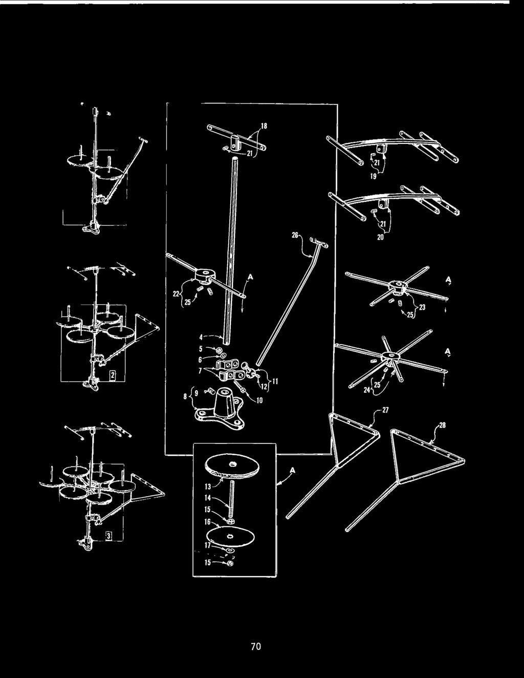
70


71 THREAD STAND PARTS Amount Required Ref. Part One Two Three Description Neede Neede Neede 20 H-2 Thread Stand, compete, for Casses 56200, H-4 Thread Stand, compete, for Casses 56400, 56500, H-6 Thread Stand, compete, for Cass B-2L!- Thread Stand Rod H Nut Washer U Lead Eyeet Ba Spit Socket A Thread Stand Base CD-4 Screw Screw T Lead Eyeet Socket Ba CD-4 Screw V Pad, for thread cone W Spoo Pin A Nut Spoo Seat Disc Washer H-2 Eyeet Support H-4 Eyeet Support H-6 Eyeet Support CD-4 Screw D-2 Spoo Seat Support D-4 Spoo Seat Support D-6 Spoo Seat Support CD-5 Screw S-2 Lead Eyeet S-4 Lead Eyeet S-6 Lead Eyeet
72 Part Page ~ SC W ,3 NU ,3,35 CL s c... 4,67,69 25 s T cc TB Bk ,47, Bk Bk Bk J A ,43 57 WB WD ,57 65 XD C067 D C067 E ,45 73 A... 45,5,55, 57,6,63, 65 HA73 B ,33,6, x u... 3, ,5,55, 57, , ,49,5, 53,57,59, 6,63,65 9 A ,6,65 9 D , ,33,43 98 A , , A SC SC A ,53,6 87 B... 43,47,5, A Part NUMERICAL INDEX OF PARTS 20 c Page ~ 258 A ,33, ,33 SC D ,49,5, 53, A... 25, , , A , ,6 74 A ,5,53, A M w A E AG-4 / E E , A Part ~ 638 M A , A E c F A ,49,53 20 H B H v A D H s T u ~, E F K L N P A AV AG AL BK BP BR Page.J!Q.:_ 2657 E ,35, w x v A c ,35, R c A , G A G B , , D A , c NOTE: Ony the basic part numbers are shown in the index. For various gauges, capacities, etc. avaiabe, refer to the istings on pages indicated. 72
73 Part A D , A R K c Page.J!Q.:_ P CB CD , L C c E , , c G A C , , c ,53,59, 6, C ,6, , E. 49,57,59, 6, G ,57,6, L R , , A C A ,57,59, C A , A A C H J Part.J!Q.:_ NUMERICAL INDEX OF PARTS C A C D E J P AA AB A BG N P Q V AB AC K J L u V u V u V BZ Page.J!Q.:_ T V ,67, V A A R AK AL v w X v AA L M N AF LL LM LN LV MJ MY NM AB AC... 6, A , AE , A H N Part.J!Q.:_ P S , c o F H J K P R S AE BV N c z , AK , G , E o A R w o w M N ,3 526 P C A w A F G A , o M L N o F K c K M AA J AC H A D F NOTE: Ony the basic part numbers are shown in the index. For various gauges, capacities, etc. avaiabe, refer to the istings on pages indicated. Page.J!Q.:_ 73
74 Part ~ Page ~ 5294 R A B u v w ,5, B J M N w F. 47, K v w... 49,5, A A M 47, N P 47, R , s Part NUMERICAL INDEX OF PARTS c E K R A A C E K R A , A B c... 6 Page 5430 D ,59, E F 39,49,5, 57,59, K R A Part ~ E B c D A A B E , A o E B J K A A A A w 47, A AC ,57,59, R w x Y z , AB , AD AE... 47, AG AH AJ AK AL AM AX BB BC BO BE BF A C o A B C G K R AD B C c D K c BR C G H M C C G BR BR D , F... 59, G , J BR A A A AA AC , B G E N o E G A A H A AL A C A B C D F G H u o N NOTE: Ony the basic part numbers are shown in the index. For various gauges, capacities, etc. avaiabe, refer to the istings on pages indicated. Page 74


75 Part B C AL , E , F , G , H J K L M N P R s T u V w x v AA AB AD , AE AF , AG , AH , AJ , AK.... 5, AL AM AN AP , AR AU , AX , B F L N P D G L B C D E F G M D E , c E F B C D E NOTE: Page ~ Part ~ NUMERICAL INDEX OF PARTS F G c o A A B C D E C E B c D E G H J K L M N X Y AA AB AC A D AA AB E G H , J , E... 37, F c D J L P Q T w A B C A Page Part Page ~ ~ A B B c E C , A B A C , B C , A , E A A A A A A A B B K A A G L J AJ AN BT , 49, G F G K Ony the basic part numbers are shown in the index. For various gauges, capaci t ies, etc. avaiabe, refer to the istings on pages indicated. 75


76 WORLDWIDE SALES AND SERVICE Union Specia Corporation maintains saes and service faciities throughout the word. These offices wi aid you in the seection of the right sewing equipment for your particuar operation. Union Specia Corporation representatives and servicemen are factory trained and are abe to serve your needs prompty and efficienty. Whatever your ocation, there is a Union Specia Corporation representative to serve you. Check with him toq_ay. It is important to remember that LEWIS and COLUMBIA machines are aso products of Union Specia Corporation, thus offering the industry the most compete ine of the Finest Quaity sewing machines. Norcross. GA Chicago. IL Daas, TX Commerce. CA New York, NY Phiadephia, PA Woburn, MA Opa-ocka, FL Montrea, Quebec Toronto. Ontario Catano, Puerto Rico Brusses, Begium Leicester, Engand Paris, France Stuttgart, W. Germany Hong Kong Other Representatives throughout a parts of the word Union Spec ia Corporation, 400 N Franki n Street. Chicago, IL 6060, U S A Union Specia, GmbH, Schwabstrasse Stutgart We-;I G rma y Pnnred in U S A
4137~- 4&2---e $ 1& ~/' ... ,., '23 ,...,, 1646' ( '2 ) 2'27
 2'27") SINGER. 460/22 -Jl. ::-: : 18666 g- l!- 8'146'2-8230 6 ',,.,., 61 023 I : I - I., v 4137-4&2---e. _, 82215. 122.,.{J 8'12., 8227JI OO I.,,, ' *' -ocu 12'271, 1326U.. IG401S 140396--ii' $ 1&-46 ---/'.,
SINGER. 460/22 -Jl. ::-: : 18666 g- l!- 8'146'2-8230 6 ',,.,., 61 023 I : I - I., v 4137-4&2---e. _, 82215. 122.,.{J 8'12., 8227JI OO I.,,, ' *' -ocu 12'271, 1326U.. IG401S 140396--ii' $ 1&-46 ---/'.,
Thomas Scientific Swedesboro, NJ U.S.A.
 Thomas Scientific Swedesboro, NJ 08085-0099 U.S.A. Wiley Laboratory Mill, Model 4 3375-E10 (115 V, 50/60 HZ) USE AND CARE OF CATALOG NUMBER: 3375-E10 Wiley Laboratory Mill, Model 4 (115 V, 50/60 HZ) UNPACKING
User s Manual Trampoline 8
 User s Manual Trampoline 8 Model! WARNING Read all precautions and instructions in this manual before using this equipment. Save this manual for future reference. Maximum user weight 17 lbs. ASSEMBLY IMPORTANT
i N O S O L i n n o v a t i v e s o l u t i o n s ü ü ü Ü Advantages: ü ü ü ü CLS Small Lever Clamp - Tiny Link Clamp
 i n n o v a t i v e s o u t i o n s Sma Lever Camp - Tiny Lin Camp hydrauic up to 230 bar, doube acting dvantages: High force generation Compact design djustabe camping point Lever Ratio 1:1 with Standard-Camp
TITAN Fuel Tanks. INSTALLATION INSTRUCTIONS G e n e r a t i o n V
 TITAN pt. no.: 02 0000 0128 Important: Please read these instructions carefully and completely before starting the installation. TITAN Fuel Tanks INSTALLATION INSTRUCTIONS G e n e r a t i o n V Extended
Product instruction manual Ream Cutting Systems RE3943, RE3946, RE3947, RE3971, RE3952E
 Product instruction manual Ream Cutting Systems RE3943, RE3946, RE3947, RE3971, RE3952E The Trimfast Ream Cutters are reliable, high performance cutters that will give you the results you need quickly
Honda Ridgeline Installation Instructions
 Honda Ridgeline Installation Instructions READ THIS... If you read these instructions from beginning to end before starting you will probably not need to look at them again during the installation, but
ASSEMBLY & CARE INSTRUCTIONS
 ASSEMBLY & CARE INSTRUCTIONS 7 x TRAILER TENT SERIES 3 9 Part No. FT3711 - on road FT3923 - off road OPTIONAL SUNROOM Wall and floor kit Part No. FT3723 - on road FT39 - off road OPTIONAL SPARE ROOM Roof,
Tank. Part B, Section 1. This section covers the following unit configurations. Pump Piston Pump (E or G)
") Part B, ection Model Voltage This section covers the following unit configurations. 3400V All Pump Piston Pump (E or G) Manifold Control 4-Port (A) Vista tandard (V) Vista Pattern (PC) Vista Temperature
Part B, ection Model Voltage This section covers the following unit configurations. 3400V All Pump Piston Pump (E or G) Manifold Control 4-Port (A) Vista tandard (V) Vista Pattern (PC) Vista Temperature
WIDESPREAD LAVATORY MODELS WITH HI-ARC SPOUT
 5951, 5961, 5981, 5983, 5993 SERIES MT122B INSTALLATION INSTRUCTIONS THESE INSTRUCTIONS MUST BE LEFT WITH HOMEOWNER WIDESPREAD LAVATORY MODELS WITH HI-ARC TRADITIONAL CROSS NOTE: Handle Inserts are not
4A1-114/114KR & 4A1-2 MANUAL TENSIONERS
 M L. C O O N AL TO 4A1-114/114KR & 4A1-2 W W W.T R AD IT IO MANUAL TENSIONERS READ THESE INSTRUCTIONS CAREFULLY. FAILURE TO FOLLOW THESE INSTRUCTIONS CAN RESULT IN SEVERE PERSONAL INJURY. GENERAL SAFETY
FLAIR TWO-HANDLE BATH & SHOWER FAUCET
 INSTALLATION INSTRUCTIONS BEFORE YOU BEGIN NOTES CAUTION: Risk of product damage. Remove plaster guards, valve units, and aspirator before you apply heat to yoke. Shut off the main water supply. Observe
ASSEMBLY & CARE INSTRUCTIONS. 7 x4 TRAILER TENT SERIES 4 9. OPTIONAL SUNROOM Wall and floor kit. OPTIONAL SPARE ROOM Roof, wall and floor kit
 ASSEMBLY & CARE INSTRUCTIONS 7 x TRAILER TENT SERIES 9 Part No. TM709 OPTIONAL SUNROOM Wall and floor kit Part No. TM723 OPTIONAL SPARE ROOM Roof, wall and floor kit Part No. TM76 Please keep these instructions
Art Thatch TM Baja TM Sub-Panel Installation
 Thatch Pane Specifications Length: 31 Height: 24 Coverage: 1.72 Sq. Ft. per pane On Center Instaation: 8 Art Thatch TM Baja TM Sub-Pane Instaation 24 Backyard X-Scapes, Inc. 10835 Sorrento Vaey Rd. San
AND LOAD CANOPY RACK SPECIFICATIONS
 8MAY15 INSTRUCTIONS for the LOCK AND LOAD CANOPY RACK SPECIFICATIONS and SAFE LOADING REQUIREMENTS The Lock and Load ladder carrier for Truck Caps is a rack designed to mount to the top of a pickup truck
Solera Classic Awning
 Solera Classic Awning OWNER'S MANUAL Page 1 Table of Contents System and Safety Information 2 Operation 3 Extending the Awning 3 Optional Car Port Position 3 Retracting the Awning 3 Fabric Replacement
STROMBERG CARLSON PRODUCTS INC.
 STROMBERG CARLSON PRODUCTS INC. Raiings Manua RV Steps Hickory Springs Auminum Steps AC TURE D BY UF H Transportation & Speciaty Manufacturing Company R White Finish Siver Sparke Finish Back Finish Repacement
DC 700 Series Hose Reel - September 2010
 Instructions Parts List Service Manual DC 700 Series Hose Reel - September 2010 Suitable for dispensing, transfer and evacuation of lubricants, fuels, air & other automotive & industrial products. To be
Otter XT 650 Cabin Installation and Set-Up Instructions
 Otter XT 650 Cabin Installation and Set-Up Instructions Otter XT 650 Cabin Fits Medium Otter Wild Sled Only Parts Identification and Check List MODEL NUMBERS: Complete Pkg Otter XT 650 Cabin 200891 2 1
JARVIS. Model 70 Airsnip Air Powered Scissors
 Air Powered Scissors EQUIPMENT SELECTION... Ordering No. Airsnip Model 70... 4019009 Air Filter/Regulator/Lubricator.. 3022003 Balancer... 1350084 Power--Pak (250 PSI)... 4026016 TABLE OF CONTENTS... Page
INSTRUCTION SHEET DETHATCHER KIT. STS-422LX LPSTS-42JD Assembly Installation Operation Repair Parts L-1660-D. Visit us on the web!
 INSTRUCTION SHEET DETHATCHER KIT MODEL: DK-422LX FOR USE WITH SWEEPER MODEL: STS-422LX LPSTS-42JD Assembly Installation Operation Repair Parts For use with Riders and Lawn/Garden Tractors For the latest
IMPORTANT OWNER-OPERATOR INSTALLATION INSTRUCTIONS. Part # A7006
 IMPORTANT OWNER-OPERATOR INSTALLATION INSTRUCTIONS Part # A7006 Parts List Wobble Stopper Body Wobble Stopper Shaft Camper Bracket Lower Bracket Assembly Upper Bracket Upper Bracket Clamp 3/8 SAE Flat
Mixer Blade Sets of Parts and Installation Procedure Using Epoxy
 Mixer Blade Installation Procedure Important Safety Notice STAY CLEAR OF MIXER UNTIL MIXER IS OFF, MAIN PANEL IS LOCKED OUT, AND ALL MIXER COMPONENTS' MOTIONS ARE STOPPED. FOLLOW STANDARD SAFETY PROCEDURES
Otter Pro XT 1200 Cottage Installation and Set-Up Instructions
 Otter Pro XT 1200 Cottage Installation and Set-Up Instructions Otter Pro XT 1200 Cottage Fits Small Ultra-Wide Otter Pro and Otter II Sled Only Parts Identification and Check List MODEL NUMBERS: Complete
300 ft. 5/8 Hose wagon
 300 ft. 5/8 Hose wagon Model 95956 Assembly And Operation Instructions Due to continuing improvements, actual product may differ slightly from the product described herein. (Garden hose is not included).
TWISTLOCK VEHICLE STABILIZER (TVS) SYSTEM INSTRUCTIONS
 SYSTEM INSTRUCTIONS") TWISTLOCK VEHICLE STABILIZER (TVS) SYSTEM 22-797010, 22-797020, 22-796161 INSTRUCTIONS COMPONENTS: 1. TVS-100, PN 22-797010: 47 60 (119 cm 152 cm) stroke TwistLock Vehicle Stabilizer. Component weight,
TWISTLOCK VEHICLE STABILIZER (TVS) SYSTEM 22-797010, 22-797020, 22-796161 INSTRUCTIONS COMPONENTS: 1. TVS-100, PN 22-797010: 47 60 (119 cm 152 cm) stroke TwistLock Vehicle Stabilizer. Component weight,
Mandolin Slicer Quite possibly the safest mandolin in the world
 Mandolin Slicer Quite possibly the safest mandolin in the world MANDOLIN & COMPONENTS Handle Upper Plate Safe Hands Food Holder Non-Slip Retractable Leg Julianne Blades (3 sizes) Waffle / Crinkle Cut Blade
PIONEER LITE PATIO AWNING OWNER'S MANUAL
 A Manual Crank Operated Awning RV OWNER'S MANUAL TABLE OF CONTENTS Introduction... 2 Operating the Awning... 3 To Open the Awning:... 3 Adjusting the Pitch... 4 Rain Release Setting... 4 Setting the Arms
RAFTER VI. Installation and Operation CAREFREE WITH AUTOMATIC AWNING SUPPORT. RV Accessory PRODUCT OVERVIEW
 CAREFREE RAFTER VI RV Accessory WITH AUTOMATIC AWNING SUPPORT Installation and Operation PRODUCT OVERVIEW The gives the awning user the ability to easily tighten the center fabric when the awning is extended.
* * 4023 KR. Step 1 Prepare the Keyed Removable Unit. Not for use on electric or fire rated removable mullions
 condition. *64009-00* 64009-00 Keyed Removable Mullions 403 KR Installation Instructions Not for use on electric or fire rated removable mullions This kit includes the following parts: (Not to scale) 5/6
DIAMOND TECH INTERNATIONAL Innovations For Creativity DIAMOND LASER BAND SAW OPERATIONS MANUAL
 SPEEDSTER-XL INSTRUCTION MANUAL DIAMOND TECH INTERNATIONAL Innovations For Creativity SPEEDSTER-XL DIAMOND LASER BAND SAW OPERATIONS MANUAL SPEEDSTER-XL INSTRUCTION MANUAL - PAGE 1 Before You Begin Read
Crimp & Cleave Termination Instructions
 A Furukawa Company Your Optical Fiber Solutions Partner Crimp & Cleave Termination Instructions for 200 µm and 400 µm ST and SMA Connectors For Use With: 200 µm and 400 µm ST and SMA Termination Kits 200
Meat Slicer INSTRUCTION MANUAL CAUTION! ONE YEAR LIMITED WARRANTY
 ONE YEAR LIMITED WARRANTY INSTRUCTION MANUAL The original registered owner of this product should contact SKYFOOD EQUIPMENT LLC at 305-868-16 for any warranty problems or service. SKYFOOD EQUIPMENT LLC
Notes, Parts List & Drawings
 Biomass Chopper/Cutter Notes, Parts List & Drawings Page 1 of 16 The Easy BioChop biomass chopper/cutter was designed to cut both wet and dry biomass and to accomplish a number of goals. The objectives
Cabinet Mount Assist Lift n Lock Instructions
 Cabinet Mount Assist Lift n Lock Instructions PART LIST 2 @ Gas Cylinder 1 @ Lock Bar 2 @ Rubber Sleeve (preset) 4 @ Stopper Pin (2pcs preset) 4 @ Saddle Block 8 @ 19mm Black PVC Cap 5 @ 14mm Black PVC
OWNER'S MANUAL CAMPOUT TABLE OF CONTENTS
 OWNER'S MANUAL CAMPOUT RV Before operating the awning, carefully review the Owner's Manual. The manual contains important safety information, detailed operating instructions, common maintenance procedures
Otter Pro XT Cabin Installation and Set-Up Instructions
 Otter Pro XT Cabin Installation and Set-Up Instructions Otter Pro XT Cabin Fits Medium Otter Pro and Otter II Sled Only Parts Identification and Check List MODEL NUMBERS: Complete Pkg Pro XT Thermal Cabin
INSTRUCTION SHEET TWISTLOCK VEHICLE STABILIZER (TVS) SYSTEM PN S: , ,
 SYSTEM PN S: , ,") INSTRUCTION SHEET TWISTLOCK VEHICLE STABILIZER (TVS) SYSTEM PN S: 22-797010, 22-797020, 22-796161 COMPONENTS: 1. TVS-100, PN 22-797010: 47 60 (119 cm 152 cm) stroke TwistLock Vehicle Stabilizer. Component
INSTRUCTION SHEET TWISTLOCK VEHICLE STABILIZER (TVS) SYSTEM PN S: 22-797010, 22-797020, 22-796161 COMPONENTS: 1. TVS-100, PN 22-797010: 47 60 (119 cm 152 cm) stroke TwistLock Vehicle Stabilizer. Component
INSTRUCTION MANUAL ALEKO RETRACTABLE AWNING
 INSTRUCTION MANUAL for ALEKO RETRACTABLE AWNING www.alekoproducts.com FAILURE TO FOLLOW THESE INSTRUCTIONS MAY RESULT IN PERSONAL INJURY! 1 Important Safety Precautions WARNING NOTE: FOR PERSONAL SAFETY,
Installation Instructions for the Rolltec Physique XL Awning
 Installation Instructions for the Rolltec Physique XL Awning Questions? Call Rolltec at 1-800-667-0474 General Tool Requirements Table of Contents Available installation brackets Side dimensions of various
Installation Instructions
 THE COLLECTION by Installation Instructions 0 BIDET FITTING Thank you for selecting American-Standard...the benchmark of fine quality for over 00 years. To ensure that your installation proceeds smoothly--please
STOP BOX SCRAPER/GRADER BLADE. Owner's Manual. Model No Safety Assembly Operation Maintenance Parts
 Owner's Manual STOP BOX SCRAPER/GRADER BLADE Model No. 486.242411 DO NOT RETURN TO STORE For Missing Parts or Assembly Questions Call 1-866-576-8388 CAUTION: Before using this product, read this manual
Crimp & Cleave Termination Instructions
 Crimp & Cleave Termination Instructions for 200 µm Factory5 Cable with ST and SMA Connectors For Use With: 200 µm ST and SMA Factory5 Termination Kits 200 µm HCS Factory5 Fiber-Optic Cable ST and SMA Factory5
42" SNOW BLADE. Owner's Manual. Model No Safety Assembly Operation Maintenance Parts
 Owner's Manual 42" SNOW BLADE Model No. 486.24443 CAUTION: Before using this product, read this manual and follow all Safety Rules and Operating Instructions. Safety Assembly Operation Maintenance Parts
NEWMAR SERVICE SCHOOL
 NEWMAR SERVICE SCHOOL TRAINING INFORMATION GUIDELINE FOR FEBRUARY 2013 OUR PRODUCTS: NOVA DUAL PITCH AWNING G-2000/ G-1500 2 P a g e G-2085 G-5000 3 P a g e G-LINKS 4 P a g e NOVA/ G-2000/ G-1500 BASIC
NS 200 Series Hose Reel January 2011
 Instructions Parts List Service Manual NS 200 Series Hose Reel January 2011 Suitable for dispensing, transfer and evacuation of lubricants, fuels, air & other automotive & industrial products. To be used
Crimp & Cleave Termination Instructions for 200 µm Factory5 Cable with ST and SMA Connectors
 Your Optical Fiber Solutions Partner Crimp & Cleave Termination Instructions for 200 µm Factory5 Cable with ST and SMA Connectors For Use With: 200 µm ST and SMA Factory5 Termination Kits 200 µm HCS Factory5
ABS Model Background Stand
 ABS Model Background Stand Product Overview: The completely redesigned Ravelli ABS model background stand is 10' tall by 12.3' wide. It is comprised of two tripod stands and four 3 cross bar sections and
Installation Guide Cable
 Installation Guide Cable Thank you for selecting a DuctSox System. This guide will be helpful for the installation of a Cable System. Sections of fabric will be labeled, assembled, bagged, and boxed for
Contents. Awnings USA - Full Protective Hood Manual Instructions ft 11" - 11ft 6" Awnings
 Awnings USA - Full Protective Hood Manual Instructions Contents Warning We recommend that two or more people are required to lift the awning into place. 4ft 11" - 11ft 6" Awnings 8 x Expansion bolts **
S E L E C T I O N. Abdominal Crunch. User manual
 and S E L E C T I O N T H E S T R E N G T H E V O L U T I O N User manual and and The identification plate of the and manufacturer, affixed along side the seat on the frame of the weight stack, gives the
Assembly instructions for Eurotramp trampolines Series: Ultimate, Grand Master Exclusiv, Grand Master, Master
 Assembly instructions for Eurotramp trampolines Series: Ultimate, Grand Master Exclusiv, Grand Master, Master 1. Assembly instructions 2. Attaching the plastic coated steel cables on the Ultimate frame
HANDWHEELS.
 HANDWHEELS 5 Handwheels Aluminum Angular Solid Handwheel...5.2 Aluminum Angular Spoked Handwheel... 5.2 Aluminum Finger Wheel... 5.10 Cast Angular Spoked Handwheel... 5.3 Cast Iron Angular Spoked Handwheel...
* * KR54-F, KR9854 & KR9954 Installation Instructions. Read All Warnings Before Starting Installation! Index:
 *941061-00* 941061-00 Keyed Removable Mullion KR54-F, KR9854 & KR9954 Installation Instructions CLASSIFIED CLASSIFIED C Read All Warnings Before Starting Installation! Index: General Information ----------------
Otter XT Cabin Installation and Set-Up Instructions
 Otter XT Cabin Installation and Set-Up Instructions Otter XT Cabin Fits Medium Otter Wild Sled Only Parts Identification and Check List MODEL NUMBERS: Complete Pkg Otter XT Cabin 200962 2 1 PARTS LIST
3x3 Pop Up Gazebo with Side Panels
 '-,- 3x3 Pop Up Gazebo with Side Panels Assembly Instructions - Please keep for future reference 650/1974 Width - 3m Depth - 3m Height - 270cm ~ Important: Make sure all the guy ropes and ~ pegs are used,
OPERATOR INSTRUCTION MANUAL INCLUDING REPAIR PARTS FOR MODULAR GENERAL PURPOSE TENT SYSTEM (MGPTS) TYPE I
 TYPE I") OPERATOR INSTRUCTION MANUAL INCLUDING REPAIR PARTS FOR MODULAR GENERAL PURPOSE TENT SYSTEM (MGPTS) TYPE I Johnson Outdoors Gear, Inc. Eureka! branded tent products 625 Conklin Road Binghamton, NY 13903
OPERATOR INSTRUCTION MANUAL INCLUDING REPAIR PARTS FOR MODULAR GENERAL PURPOSE TENT SYSTEM (MGPTS) TYPE I Johnson Outdoors Gear, Inc. Eureka! branded tent products 625 Conklin Road Binghamton, NY 13903
A&E Patio Awnings SYMPTOM
 IAGNOSTIC SERVICE MANUAL A&E This program will address the most common system problems associated with the A&E supplied by The ometic Corporation. Our intent is to provide you with a guideline of checks
DO NOT use Alien Flier Zip Line Products until you have read and fully understand the SAFETY WARNINGS below!
 SAFETY WARNING DO NOT use Alien Flier Zip Line Products until you have read and fully understand the SAFETY WARNINGS below! Assumption of Risk Zip line construction and use can be dangerous. Ensure you
INSTRUCTIONS INSTALLATION UNIVERSAL SERIES PATIO AWNING HARDWARE , , ,
 RECORD THIS INFORMATION FOR FUTURE REFERENCE: Model Number Serial Number Hardware Model Number Hardware Serial Number Date Purchased Retailer / Qualified Installer INSTALLATION INSTRUCTIONS UNIVERSAL SERIES
Tuf-Lite and Tuf-Lite II Fans 6000M Series Hub
 Tuf-Lite and Tuf-Lite II Fans 6000M Series Hub INSTALLATION MANUAL Adjustable Pitch Fan Assembly 32.8 or 10 Meter Diameter Hudson Tuf-Lite and Tuf-Lite II fan blades Hudson Tuf-Lite (black) fan blades
SOLHARO ASSEMBLY & INSTALLATION INSTRUCT IONS
 A. Introduction: SOLHARO ASSEMBLY & INSTALLATION INSTRUCT IONS Rev. 01/30/2012 The Solharo is an external, retractable, tensioned sun shading system designed to fit over a sunroom or wood pergola. The
Primrose Awnings - Standard Manual Instructions
 Primrose Awnings - Standard Manual Instructions Contents Warning 1.5m - 3.0m Awnings 4 x Expansion bolts (2 per bracket)** 2 x brackets 1 x Awning 1 x Winder handle 3.5m - 4m Awnings 6 x Expansion bolts
BigStack. Minimum Crossbar spread 24 For factory racks: Check fitlist notes, or Yakima.com for your vehicle s crossbar spread.
 BigStack Minimum Crossbar spread 24 For factory racks: Check fitlist notes, or Yakima.com for your vehicle s crossbar spread. HEAVY Duty strap (2x) PAD (4x) ADJUSTMENT KNOB (2x) T-BOLT (2x) BAIL (2x) BigStack
SPIRAL SLICER Instruction Manual Model #5280 & 5280M. Part No Revised Feb. 2010
 SPIRAL SLICER Instruction Manual Model #5280 & 5280M Part No. 82876 Revised Feb. 2010 SAFETY PRECAUTIONS INSTALLATION INSTRUCTIONS Inspection of Shipment: 5280 & 5280M SPIRAL SLICER Unpack all cartons
Insruction manual Dukki
 Insruction manual Dukki Introduction Pg. 1 Product description Pg. 2 3 Assembly and disassembly Pg. 4 Installation and adjustment Pg. 5 12 Maintenance Pg. 13 Parts Pg. 14-17 INDEX 1. Introduction 1 2.
1612P MODEL 1612P SLICER MODEL EXECUTIVE OFFICES 701 RIDGE AVENUE TROY, OHIO FORM (4-95)
") 1612P MODEL 1612P SLICER MODEL 1612P ML-104587 EXECUTIVE OFFICES 701 RIDGE AVENUE TROY, OHIO 45374-0001 FORM 19370 (4-95) Installation, Operation, and Care of MODEL 1612P SLICER SAVE THESE INSTRUCTIONS
1612P MODEL 1612P SLICER MODEL 1612P ML-104587 EXECUTIVE OFFICES 701 RIDGE AVENUE TROY, OHIO 45374-0001 FORM 19370 (4-95) Installation, Operation, and Care of MODEL 1612P SLICER SAVE THESE INSTRUCTIONS
OWNER'S MANUAL AWNING EXTEND R TABLE OF CONTENTS
 OWNER'S MANUAL AWNING EXTEND R RV Before operating the awning, carefully review the Owner's Manual. The manual contains important safety information, detailed operating instructions, common maintenance
MODEL # 1 MANUAL CAN OPENER
 REV.B SERVICE MANUAL MODEL # 1 MANUAL CAN OPENER Model #1 Can Opener Assembly Procedure The Model #1 can opener will be assembled according to the following procedure. I. Model #1 Handle and Arbor Assembly
functionality with the necessary maintenance tools stored in a convenient built in tool box, as well as parallel handles for
 GuilloMax User Manual The Guillomax has distinct features such as its unique structure and ease of cutting. It combines symmetry with functionality with the necessary maintenance tools stored in a convenient
Core Systems Installation Instructions
 185-3017 185-3018 185-3517 607-0149 WLH 09/17/18 TABLE OF CONTENTS ***Assembly*** Roller Tube Assembly Roller Tube Assembly... Standard Application Attaching Tarp to Roller Tube - Standard... Installing
/ Tool and Equipment Safety Tether System (T.E.S.T.S)
") 20 INSTRUCTIONS FOR USE AND PRODUCT GUIDE 799953 / 799955 Tool and Equipment Safety Tether System (T.E.S.T.S) Part # T353012 Rev 2 Reliance Industries LLC 2802 East X Street Deer Park, Texas 77536 281-930-800
20 INSTRUCTIONS FOR USE AND PRODUCT GUIDE 799953 / 799955 Tool and Equipment Safety Tether System (T.E.S.T.S) Part # T353012 Rev 2 Reliance Industries LLC 2802 East X Street Deer Park, Texas 77536 281-930-800
PROCESS RELIABILITY RATHER THAN NERVE TINGLING BY GÜHRING GM 300 CHECK AND MEASURING INSTRUMENTS FOR OPTIMAL TOOL CLAMPING
 PROCESS RELIABILITY RATHER THAN NERVE TINGLING BY GÜHRING GM 300 CHECK AND MEASURING INSTRUMENTS FOR OPTIMAL TOOL CLAMPING AND ubrication Check- and Measuring instruments Optima too camping and ubrication
Solera Classic Awning OEM INSTALLATION MANUAL
 Solera Classic Awning OEM INSTALLATION MANUAL TABLE OF CONTENTS System and Safety Information 2 Preparation 3 Resources Required 3 Installation 3 Installing the Awning Rail (If Necessary) 3 Assembling
HARD DOOR UPGRADE KIT
 RV Accessories OWNER'S MANUAL HARD DOOR UPGRADE KIT FOR ADD-A-ROOM & BREEZEWAY SCREEN ROOMS THIS MANUAL SUPPLEMENTS THE ADD-A-ROOM INSTRUCTIONS TABLE OF CONTENTS First Time Assembly... 2 Assembling the
BowDown. MiniMuM Crossbar spread 24 (61CM) Steel Hook (2X) Buckle Strap (2X) Plastic Tube (2X) Plain Strap (2X) SHORT BLACK T-BOLT (2x) BOWDOWN (2x)
 Steel Hook (2X) Buckle Strap (2X) Plastic Tube (2X) Plain Strap (2X) SHORT BLACK T-BOLT (2x) BOWDOWN (2x)") BowDown MiniMuM Crossbar spread 24 (61CM) Heavy Duty strap (2x) SHORT BLACK T-BOLT (2x) BOWDOWN (2x) Bow Stern Tie Down Buckle Strap (2X) Plastic Tube (2X) Plain Strap (2X) Steel Hook (2X) IMPORTANT WARNING
BowDown MiniMuM Crossbar spread 24 (61CM) Heavy Duty strap (2x) SHORT BLACK T-BOLT (2x) BOWDOWN (2x) Bow Stern Tie Down Buckle Strap (2X) Plastic Tube (2X) Plain Strap (2X) Steel Hook (2X) IMPORTANT WARNING
PARTS BOOK FLAIL HEADS 90 REAR 3PT HITCH MOUNT
 PARTS BOOK FLAIL HEADS 90 REAR 3PT HITCH MOUNT 5.0.8 DIAMOND MOWERS, LLC 350 E 60 th St. North Sioux Falls, SD 5704 FOR WARRANTY CALL DIAMOND MOWERS DIRECT: 888-960-0364 OUR TECHNICIANS WILL DIAGNOSE YOUR
INSTALLATION INSTRUCTIONS TOWNSEND
 INSTALLATION INSTRUCTIONS TOWNSEND.00 DECK MOUNT BATH FILLER.0 Thank you for selecting American Standard... the benchmark of fine quality for over 00 years. To ensure that your installation proceeds smoothly-please
Installation Guide: Round Trampoline
 Trampolines & trampoline parts designed to survive in the harsh Oz climate. www.oztrampolines.com.au Installation Guide: Round Trampoline Safety Tips Here at Oz Trampolines we are passionate about your
PARTS LIST MODEL BLE1AT. For Europe. Serial Numbers From. Vol.3.1RoHS
 PARTS LIST MODEL BLEAT For Europe Serial Numbers From 06-70380 To Vol.3.RoHS . ARM BED & COVERS 2 20 26 22 28 2 3 2 4 23 27 7 8 8 4 3 2 9 6 0 7 9 6 .ARM BED & COVERS NO. PARTS NUMBER Q'TY DESCRIPTION B00-3B
RETRACTABLE AWNING w/ OPTIONAL HOOD ASSEMBLY INSTRUCTIONS
 Contact us @ (800)851-0865 RETRACTABLE AWNING w/ OPTIONAL HOOD ASSEMBLY INSTRUCTIONS Congratulations on your purchase of a new retractable awning. With proper installation this awning will provide years
SERVICE MANUAL- M126
 SERVICE MANUAL- MANUAL CAN OPENER- MODEL # 2 1 Model #2 Can Opener Assembly Procedure The Model #2 can opener will be assembled according to the following procedure. I. Model #2 Handle and Arbor Assembly
A Note To You 2. Parts And Features 5. Using Your Oven 6. KZlZZfing Cycle 19. Warranty Cd us with question or comments.
 A Note To You 2 Parts And Features 5 Using Your Oven 6 KZZZfing Cyce 19 Warranty 28 1-800-253-1301 Cd us with question or comments. SELF-CLEANING ELECTRIC UNDERCOUNTER b-q BUILT-IN OVEN MODEL RB262PXY
Installation Instructions for the Rolltec Adalia X3M Extenda Awning
 Installation Instructions for the Rolltec Adalia X3M Extenda Awning Questions? Call Rolltec at 1-800-667-0474 General Tool Requirements Table of Contents Available installation brackets Side dimensions
10 X 20 X 8 Dome Canopy
 10 X 20 X 8 Dome Canopy Warning Keep all flame and heat sources away from this tent fabric. Refer to labels for flamability specification. It is not fire proof. The tent fabric will burn if left in continuous
INSTALLATION & MAINTENANCE MANUAL SERIES 9000 MODELS 9150/9300 SERIES 9000 VALVES WITH V BALL
 BRIEF INTRODUCTION Split body (2-piece) valve allows easy replacement of gasket, seal, and seats without special tools. Series 90D ball valves use floating ball design. Induced by the line pressure the
Installation Instructions for Wall Mount, Deck Mount and Pre-rinse Faucets
 Installation Instructions for Wall Mount, Deck Mount and Pre-rinse Faucets SAVE FOR END USER ELKAY 2222 CAMDEN COURT OAK BROOK, IL 60523 USA WALL MOUNT ASSEMBLY General Instructions Turn off the water
Swagelok Thermoplastic Hose Hand Swager User s Manual
 Swagelok Thermoplastic Hose Hand Swager User s Manual Thermoplastic Hose Hand Swager User s Manual Contents Hand Swager Components....................... 2 Setup Swager.......................................
Crimp & Cleave Termination Instructions
 Your Optical Fiber Solutions Partner Crimp & Cleave Termination Instructions for 200 µm Harsh Environment SMA For Use With: 200 µm HE SMA Termination Kit 200 µm HCS Fiber-Optic Cable HE SMA 200 µm Crimp
Instruction for edge trimming knife sharpening of M-Type shoe sewing machines
 Instruction for edge trimming knife sharpening of M-Type shoe sewing machines 1. Introduction This instruction is a supplement to the instruction for use of electric table sharpener; thus the scope of
Zippers, Zippers, and More Zippers with Donna Cash
 Zippers, Zippers, and More Zippers with Donna Cash Let s talk about closure, closure with zippers! In this class you will learn all about the different types of zippers and how to insert these in a variety
Butler Personnel Parachute Systems, LLC
 Butler Personnel Parachute Systems, LLC 1820 Loudon Avenue NW PO Box 6098 Roanoke, VA 24017-0098 (540) 342-2501 (540) 342-4037 (FAX) Info@butlerparachutes.com Butler Personnel Parachute Systems Back Pack
International Scout 80/800
 International Scout 80/800 Tools needed: sockets wrenches powered drill #2 phillips bit for drill #3 phillips bit for drill or screwdriver tape measure Contents: 2- bedrails, (2 pieces each) 4- bedrail
Installation Guide. Single-Control Kitchen Sink Faucets
 Installation Guide Single-Control Kitchen Sink Faucets K-6352 K-6353 M product numbers are for Mexico (i.e. K-12345M) Los números de productos seguidos de M corresponden a México (Ej. K-12345M) Français,
Carbon Lite Volleyball system ( Either in packages or components ordered separately )
") Instruction Manual VB7222 Carbon Lite Volleyball system ( Either in packages or components ordered separately ) Customer Service (800) 247-7668 P A R T S L I S T Item Qty Description Item Qty Description
Instruction Manual VB7222 Carbon Lite Volleyball system ( Either in packages or components ordered separately ) Customer Service (800) 247-7668 P A R T S L I S T Item Qty Description Item Qty Description
INSTALLATION INSTRUCTIONS AND OWNER'S MANUAL AWNINGS. For trailers & motor homes with straight sides TOOLS REQUIRED
 AWNINGS INSTALLATION INSTRUCTIONS AND OWNER'S MANUAL For trailers & motor homes with straight sides TOOLS REQUIRED 1/4" electric drill Ratchet handle kit 3/8" & 7/16" socket No. 1 and No. 2 screwdriver
PRODUCT MANUAL - M096
 PRODUCT MANUAL - M096 MODEL 270 ELECTRIC CAN OPENER 1 I. LABELS L087--CAUTION 2 II. SPECIFICATIONS MODEL NO. 270 POWER 115 VOLT, 1.5 AMP, 50-60HZ REQUIREMENTS 230 VOLT, 0.8 AMP, 50-60 HZ NORMAL SPEED 200-250
Eaton ET Hydraulic Hose Saw INSTRUCTION MANUAL
 Eaton ET9100-07-110 Hydraulic Saw INSTRUCTION MANUAL INSTRUCTION MANUAL Eaton ET9100-07-110 Hydraulic Saw Table of Contents Introduction... 3 Old Method... 3 New Eaton Method... 3 Operation... 4 Operation
Suggested Installation Instructions for: , Embroidered Front End Mask
 I I 1 Suggested Installation Instructions for: 602-246, 1975-1979 Embroidered Front End Mask 2-Cover Hooks 4-Air Foil Inserts 2-2" "U" Shaped Trim Locks 4-2" ADHESIVE BACKED Hook Strips 2-14" ADHESIVE
0: ae
 USA SERVICE OFFICE The Dometic Corp. 509 So. Poplar st. LaGrange, IN 46761 CANADA Dometic Dist 866 Langs Dr. Cambridge, Ontario CANADA N3H N7 0: ae 8000,8500&9000 @ Fabric Roller Tube Assembly with Universal