AND LOAD CANOPY RACK SPECIFICATIONS
|
|
|
- Eleanore Jordan
- 6 years ago
- Views:
Transcription
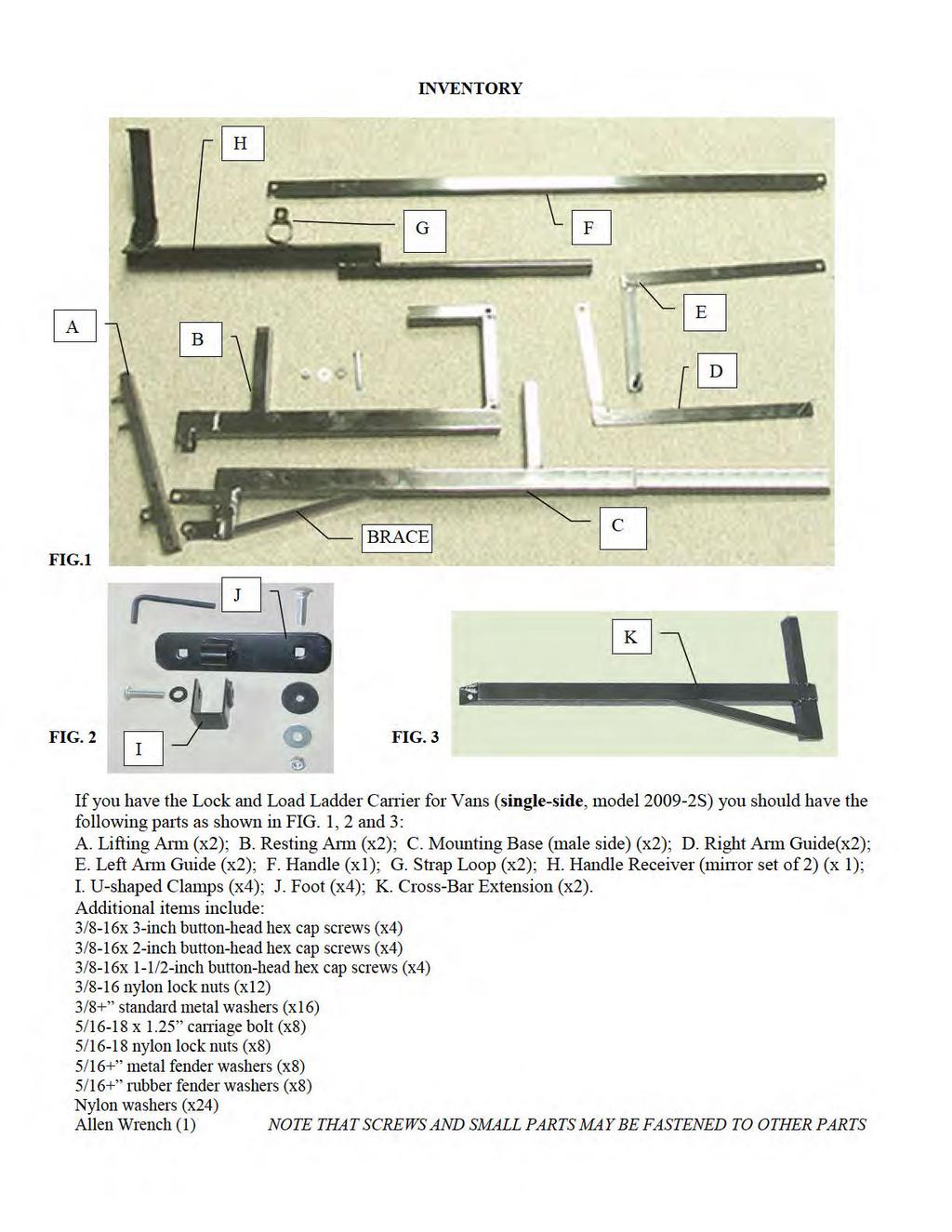
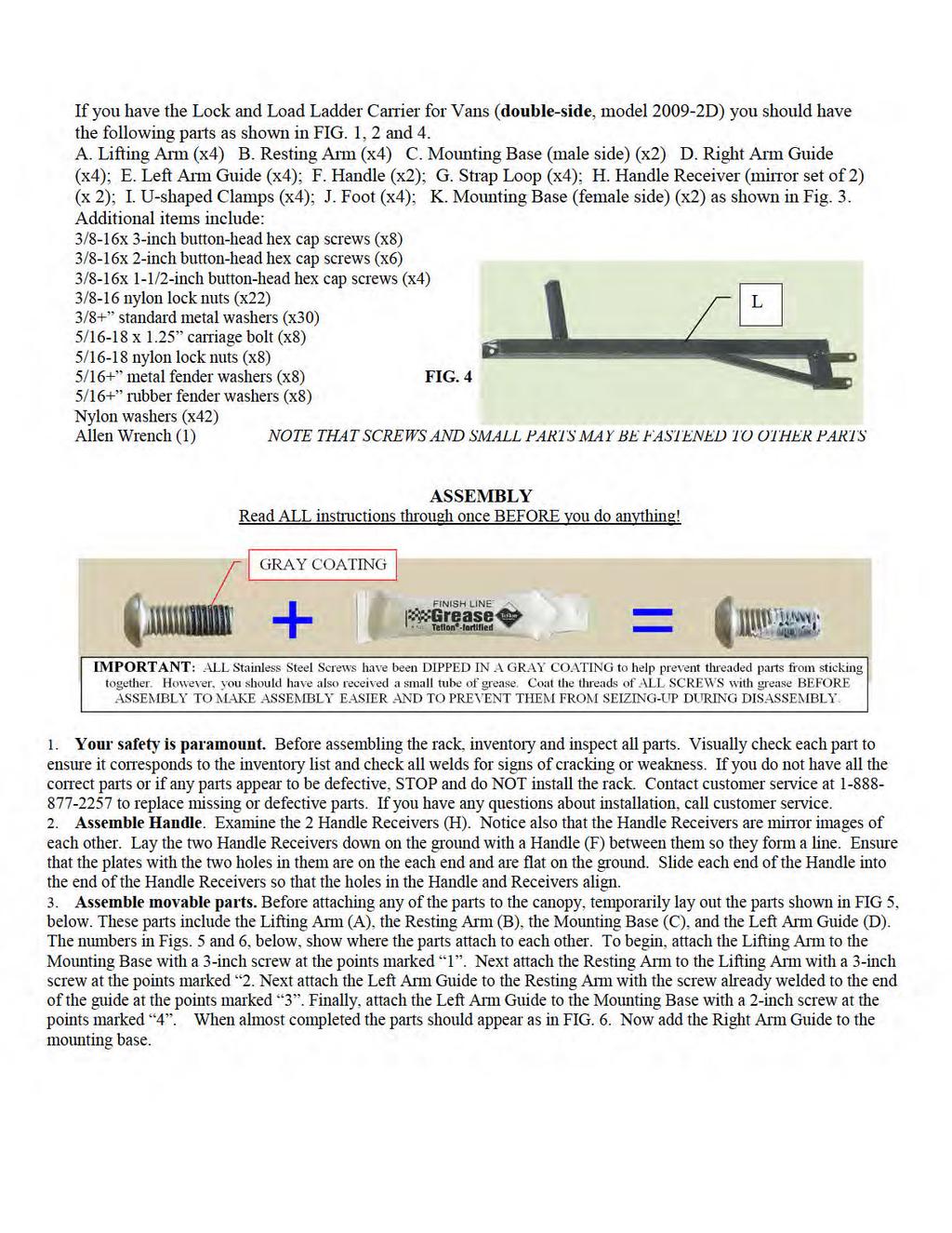
1 8MAY15 INSTRUCTIONS for the LOCK AND LOAD CANOPY RACK SPECIFICATIONS and SAFE LOADING REQUIREMENTS The Lock and Load ladder carrier for Truck Caps is a rack designed to mount to the top of a pickup truck camper shell. The rack can carry one ladder not exceeding 65 lbs in each side of the rack with the load distributed evenly between the front and back portions of the rack. Model S has a ladder loader on one side and model D has ladder loaders on both sides. In addition to carrying ladders in the loader, cargo may also be carried on the crossbars that span the other side of the roof of the cap on model S. However, the maximum collective weight of all cargo loaded on either the S or the D must not exceed 150 lbs nor can it exceed the maximum strength of the camper shell. This carrier is designed to carry loads, which are evenly distributed between the front and rear arms of the carrier. Do not carry ladders where a force of over 35 lbs. is concentrated on either arm and do not carry ladders with a carrying length exceeding 2.5 times the distance between the arms. This product is not warranted for use off-road or on unimproved, poorly maintained, or bumpy roads, nor is it warranted when used contrary to instructions or specified uses. U.S. Rack does NOT warrant any automotive product to which the carrier is attached. Ensure the rack to which the carrier is attached is sturdy enough to support the loaded carrier during use. U.S. Rack is not responsible for injury or property damage resulting from the carrier being improperly installed or used. Loads extending beyond the rear bumper of the vehicle must be designated with a red flag during daylight or red light during darkness in accordance with state law. BE SAFE: Be aware that the when the carrier opens, it extends down and the ladder slides suddenly toward you. Always open the carrier slowly to prevent the ladder from falling off the carrier onto you. This is especially important if the truck is not parked on level ground. Do not drive the vehicle when the carrier is in the open position. Ensure ladder is properly seated in the closed carrier with a lock or clevis pin installed in each arm to insure the carrier cannot open. Make sure all threaded connections remain tight. Check tightness each time you install or load the carrier, as well as daily to ensure that all connections remain tight. Periodically check welds for cracking caused by use. Also check the condition of rain gutters to ensure they remain structurally strong. Remember that the carrier raises the profile of the vehicle. High loads must be transported with GREAT CAUTION to prevent loads from striking low overhead objects such as garage door headers. WARRANTY for Lock and Load Ladder Carrier U.S. Rack products are warranted for a period of one year against all structural defects in materials and workmanship provided that they are assembled, installed, and used in accordance with all manufacturer s specifications and instructions. U.S. Rack cannot warrant the powder-coating on its products. Normal use of any powder-coated rack and exposure to weather can result in scratching of the surface, exposing metal below; therefore, maintenance on your rack will be required. To prevent rust, spot paint any scratches or breaks in the surface with a high quality metal paint. Merchandize must be returned in the original box and packaging. See return policies and procedures at
2
3
4

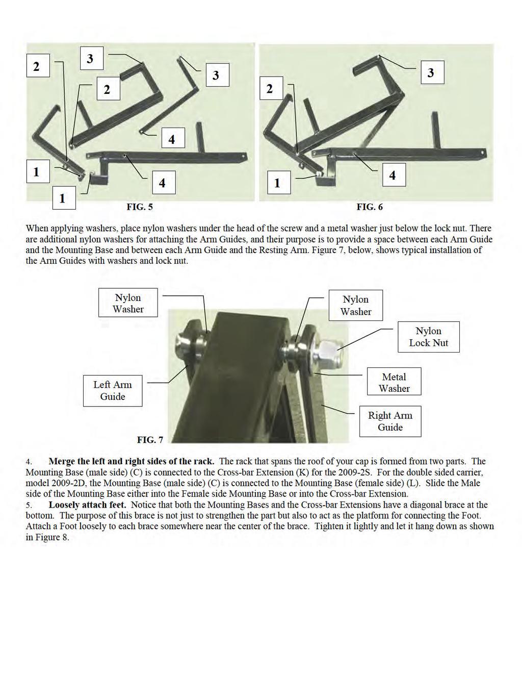
5 FIG. 8 INSTALLATION 6. Position Rack on cap. Place the back section of the rack on the back of the roof of your camper shell. Place it in such a way that the foot can be positioned near the edge of the cap as shown in FIG. 8, above. The edge of the cap is the strongest part of the roof for load bearing. Allow the end of the Mounting Base or Cross-bar Extension to overhang the edge of the cap. Gently open the lifting arm and let it hang down. Ensure that when the Lifting Arm is hanging all the way down there are several inches of clearance between it and the side of your camper shell. Adjust the location of the feet by sliding them along the bar to ensure that the carrier is high enough to easily clear the roof with at least an inch of clearance between the bottom of the carrier and the top of the cap. Once you are satisfied with the position, tighten the screw on the U-clamp with the Allen wrench to keep it from moving, then place the front section of the rack at the front of the cap in a similar manner to the back. After both the front and back sections are in position use a tape measure to measure the distance between the front and back sections on the driver side of the cap. Then measure the distance on the passenger side. Compare the two measurements and adjust the position of each section until they are the same and the two sections are parallel to each other. 7. Fix length of Handle. After measuring the distance between the centers of each Lifting Arm, adjust the handle assembly so that the holes in the plates at each end of the Handle receivers are the same distance apart. Also center the handle so that it goes into each receiver an equal amount on each end. Ensure that at least 4 inches of Handle extends into the receivers on both sides. Make a pencil mark on the handle at the center of hole in each Handle Receiver, then remove the handle. Using a 3/16 bit in an electric drill, make a hole through the handle at each mark, then reassemble with the Handle Receivers and align the holes. Pick up a Strap-Loop and place it down on the assembly so that the 3/8-inch hole in each loop aligns with the holes in the Handle and Receiver. Place a nylon washer under the head of a 2-inch button-head cap screw and then insert the screw down through the parts and affix them together using a metal washer and nylon lock nut on the other side as shown in Figs. 9 and 10. FIG. 9 FIG. 10


6 8. Attach Handle to Lifting Arms. Align the two holes on each end of the handle receivers with the studs on each Lifting Arm. Orient the tube so it is parallel to the ground, and ensure that the Strap Loops are facing upward. Connect Handle and Arms by inserting the threaded studs in the Lifting Arm through the two holes in each Handle Receiver and then secure all with metal washers and nylon lock nuts. See Figs. 11 and 12. If the Lifting Arms are too far apart or two close together you may move them on the roof of the cap or you may lengthen or shorten the Handle Assembly by drilling additional holes in the Handle. You may attach a short piece of rope or strap attached to the strap loops. This may be used to pull the handle down without your having to reach as high. Lower the Lift Arms gently by the Handle and ensure again that there are several inches of space between the lifting handle and the side of the Cap. If the Handle is too close to the side loosen the U-clamp and move the Mounting Base toward the outside and then retighten. FIG. 11 FIG Attach both side of carrier and carrier to cap. Once you are fully satisfied with the position of the Mounting Bases/Crossbar Extension you will need to set the location of the feet as well as the length of the cross-bar. Make a pencil mark through each of the holes in the four feet on the top of the cap. Also look for the hole near the end of the Cross-bar Extension or Female Mounting Base. Make a pencil mark on the Male Mounting Base through the hole near the end of the Cross-bar Extension or Female Mounting Base. After marking, remove the entire rack from the camper shell and drill a hole straight through the Male Mounting Base. Slide the two parts together and attach with a 2-inch screw with a black nylon washer on one side and a metal washer and nylon lock nut on the other. Tighten firmly until the assembly is one rigid piece as shown in FIG. 13. FIG. 13 Before re-installing the rack on the cap, drill a hole with an electric drill and 5/16 bit down through the top of the shell at each pencil mark on the roof. After drilling, reposition the rack so that the holes in the feet line up with the holes in the roof. For waterproof sealing, apply a good quality silicon caulk to each hole. Insert a carriage bolt down into each hole and apply a rubber washer, then a metal washer, and finally a nylon lock nut on the bottom side of the roof. Tighten securely. 10. Final Adjustment. It is important to ensure that both sections of the Ladder Carrier are mounted so that they are level and parallel to each other. If they are not, the Handle will not work properly to move them smoothly up and down together. After checking the alignment of the Front and Back sections of the rack, open and close the ladder carrier(s) a few times slowly using the handle to ensure that the parts are aligned and are not too close to the side of the cap. Ensure the U-clamps are fully tightened around the braces and tighten all other nuts firmly but not so tightly that they strip threads or deform parts. Do not tighten the moving parts of the rack so much that they bind together. Nylon lock nuts are used to avoid screw vibrating loose. Please be Safe. Periodically check the tightness of all threaded parts. This is crucial to ensuring that your ladder and the carrier remain safe and fully intact on your vehicle


7 Mounting a Ladder Stage 1 Carrier fully open, ladder hung from Lifting Arm Extension Hang the ladder horizontally on both the front and rear sections of the carrier so that it is suspended from the Lifting Arm. Ensure the ladder is centered on the rack and that a Lifting Arm goes between ladder rungs on both ends of the ladder. This way the ladder cannot fall off. Stage 2 Ladder rotates into lifting position Rotate the bottom side of the ladder upward over 180 degrees until the bottom side of the ladder is on top and resting against the Resting Arm. Stage 3 Ladder moves upward Grab the handle in the center with both hands. Lift and pull outward so that the Lifting Arms on both sides rotate upward. Note that as the handle is lifted, the bottom side of the ladder begins to move up the Lifting Arm, while the top side of the ladder slides up the Resting Arm. Stage 4 Ladder moves fully onto Resting Arm As the Handle is raised to nearly its highest position the lower side of the ladder slides onto the Resting Arm. Stage 6 Ladder is fully closed When handle finishes its upward motion, both sides rest fully on the Resting Arm. Stage 7 Carrier is locked When the carrier is closed, place a clevis pin or padlock through the locking eyes to prevent movement of the Mounting Base and Lifting Arm as shown. The vehicle must not be moved without the carrier being fully locked.
FLEX KEY ASSEMBLY. ..._ o RAFTER ARM TUBE MAIN ARM TUBE CAP NUT CLAW HINGE
 ZIP DEE Inc. 96 Crossen Ave. Elk Grove Village, IL 60007(847)437-0980 (800)338-2378 HEAD CASTING AWNING RAIL FLEX KEY ASSEMBLY..._ o GM1 Installation Instruction GMC Motorhome RAFTER ARM TUBE MAIN ARM
80070 TOP MOUNT CAMPER SHELL and TRANSIT CONNECT RACK TMCS_3:1
 ASSEMBLY INSTRUCTIONS for : 80070 TOP MOUNT CAMPER SHELL and TRANSIT CONNECT RACK TMCS_3:1 (916) 638-8703 (800) 343-7486 11261 Trade Center Drive Rancho Cordova, CA 95742 www.kargomaster.com Transit ASSEMBLY
IMPORTANT OWNER-OPERATOR INSTALLATION INSTRUCTIONS. Part # A7006
 IMPORTANT OWNER-OPERATOR INSTALLATION INSTRUCTIONS Part # A7006 Parts List Wobble Stopper Body Wobble Stopper Shaft Camper Bracket Lower Bracket Assembly Upper Bracket Upper Bracket Clamp 3/8 SAE Flat
Installation Instructions for the Rolltec Adalia X3M Extenda Awning
 Installation Instructions for the Rolltec Adalia X3M Extenda Awning Questions? Call Rolltec at 1-800-667-0474 General Tool Requirements Table of Contents Available installation brackets Side dimensions
Installation Instructions for the Rolltec Physique XL Awning
 Installation Instructions for the Rolltec Physique XL Awning Questions? Call Rolltec at 1-800-667-0474 General Tool Requirements Table of Contents Available installation brackets Side dimensions of various
DO NOT USE WITH CROSSBAR SPREAD LESS THAN 24.
 TM Please read all instructions carefully before assembly, installation and/or use of this product. DO NOT USE WITH CROSSBAR SPREAD LESS THAN 24. WARNING: Do not exceed the weight limit of your vehicle
P3000 UNIVERSAL Clamp-On
 IHI INSTRUCTION MANUAL Required Tools P3000 UNIVERSAL Clamp-On Wrench Allen Key P3001 65 ENDCAPS P3011 65 BLACK P300 7 ENDCAPS P301 7 WHITE P3003 ENDCAPS P3013 SILVER PART# DESCRIPTION ENDCAPS SIDE SUPPORTS
CONVEX Awning Instructions
 CONVEX Awning Instructions IMPORTANT NOTE: Please take a few minutes to become familiar with this entire document BEFORE beginning your installation. The time you spend doing this is well spent and will
Vanagon Ladder Kit Assembly & Installation Instructions
 Rocky Mountain Westy Vanagon Ladder Kit Assembly & Installation Instructions Introduction Thank you for purchasing the Rocky Mountain Westy Vanagon Ladder Kit. We pride ourselves in the products we develop
INSTALLATION INSTRUCTIONS AND OWNER'S MANUAL AWNINGS. For trailers & motor homes with straight sides TOOLS REQUIRED
 AWNINGS INSTALLATION INSTRUCTIONS AND OWNER'S MANUAL For trailers & motor homes with straight sides TOOLS REQUIRED 1/4" electric drill Ratchet handle kit 3/8" & 7/16" socket No. 1 and No. 2 screwdriver
Standard Awning Installation Instructions
 Standard Awning Installation Instructions Important Note: Please become familiar with this entire document BEFORE beginning your installation. The time you spend doing this is well spent and will make
Honda Ridgeline Installation Instructions
 Honda Ridgeline Installation Instructions READ THIS... If you read these instructions from beginning to end before starting you will probably not need to look at them again during the installation, but
Assembly TOOLS REQUIRED: 17mm and 14mm or equivalent wrenches.
 Instructions for 3 Trimmer Rack, 3TR* *Patents Pending Assembly TOOLS REQUIRED: 17mm and mm or equivalent wrenches. 15 26 26 16 15 16 Attach the lower mounting brackets to the Trimmer Rack poles as shown
DURA WHEEL CHAIR LOCKER ASSEMBLY INSTRUCTIONS
 DURA WHEEL CHAIR LOCKER ASSEMBLY INSTRUCTIONS 1. Locate a Frame and Door: Start by locating a frame and door. 2. Front Frame: Now stand up the frame and door in the desired assembly area. 3. Exterior Wall:
Installation Instructions for the Rolltec Bravo Awning
 Installation Instructions for the Rolltec Bravo Awning Questions? Call Rolltec at 1-800-667-0474 Table of Contents Available installation brackets Side dimensions of various installations Determining installation
RAFTER VI. Installation and Operation CAREFREE WITH AUTOMATIC AWNING SUPPORT. RV Accessory PRODUCT OVERVIEW
 CAREFREE RAFTER VI RV Accessory WITH AUTOMATIC AWNING SUPPORT Installation and Operation PRODUCT OVERVIEW The gives the awning user the ability to easily tighten the center fabric when the awning is extended.
IMPORTANT OWNER-OPERATOR INSTALLATION INSTRUCTIONS C2204A
 IMPORTANT OWNER-OPERATOR INSTALLATION INSTRUCTIONS C2204A Warnings Truck Bed and Camper Protection Torklift does not recommend installing your camper on top of a plastic bed liner (or other compressible
NEWMAR SERVICE SCHOOL
 NEWMAR SERVICE SCHOOL TRAINING INFORMATION GUIDELINE FOR FEBRUARY 2013 OUR PRODUCTS: NOVA DUAL PITCH AWNING G-2000/ G-1500 2 P a g e G-2085 G-5000 3 P a g e G-LINKS 4 P a g e NOVA/ G-2000/ G-1500 BASIC
User s Manual Trampoline 8
 User s Manual Trampoline 8 Model! WARNING Read all precautions and instructions in this manual before using this equipment. Save this manual for future reference. Maximum user weight 17 lbs. ASSEMBLY IMPORTANT
1946 READ AND SAVE THESE INSTRUCTIONS!
 EasyAwn Installation, Care and Maintenance Manual EasyAwn Quality, Since 1946 EasyAwn, LLC Toll Free: 877-EasyAwn http://www.easyawn.com READ AND SAVE THESE INSTRUCTIONS! EasyAwn Quarter Round Awning Installation
Urea/Adblue Hose Reel
 www.scintex.com.au sales@scintex.com.au Model: SHR3408 Urea/Adblue Hose Reel Product Manual Specifications Spring driven drum: for automatic rewind. Locking ratchet: to maintain the desired length of hose
LITE Spear Awning Instructions
 LITE Spear Awning Instructions IMPORTANT NOTE: Please take a few minutes to become familiar with this entire document BEFORE beginning your installation. The time you spend doing this is well spent and
4Runner Soft Top Installation Instructions
 4Runner Soft Top Installation Instructions Very important!! We believe that if you read these instructions from start to finish and look at all the pictures you will probably be able to do the entire installation
READ AND SAVE THESE INSTRUCTIONS! EasyAwn Standard Awning Installation
 EasyAwn Installation, Care and Maintenance Manual EasyAwn Quality, Since 1946 EasyAwn, LLC Toll Free: 877-EasyAwn http://www.easyawn.com READ AND SAVE THESE INSTRUCTIONS! EasyAwn Standard Awning Installation
IMPORTANT OWNER-OPERATOR INSTALLATION INSTRUCTIONS C3215/C3215A
 IMPORTANT OWNER-OPERATOR INSTALLATION INSTRUCTIONS C3215/C3215A Minor movement (or settling) can occur in some incidental harsh driving conditions (On or off road). A rubber bed mat is not a requirement
BigStack. Minimum Crossbar spread 24 For factory racks: Check fitlist notes, or Yakima.com for your vehicle s crossbar spread.
 BigStack Minimum Crossbar spread 24 For factory racks: Check fitlist notes, or Yakima.com for your vehicle s crossbar spread. HEAVY Duty strap (2x) PAD (4x) ADJUSTMENT KNOB (2x) T-BOLT (2x) BAIL (2x) BigStack
BowDown. MiniMuM Crossbar spread 24 (61CM) Steel Hook (2X) Buckle Strap (2X) Plastic Tube (2X) Plain Strap (2X) SHORT BLACK T-BOLT (2x) BOWDOWN (2x)
 Steel Hook (2X) Buckle Strap (2X) Plastic Tube (2X) Plain Strap (2X) SHORT BLACK T-BOLT (2x) BOWDOWN (2x)") BowDown MiniMuM Crossbar spread 24 (61CM) Heavy Duty strap (2x) SHORT BLACK T-BOLT (2x) BOWDOWN (2x) Bow Stern Tie Down Buckle Strap (2X) Plastic Tube (2X) Plain Strap (2X) Steel Hook (2X) IMPORTANT WARNING
BowDown MiniMuM Crossbar spread 24 (61CM) Heavy Duty strap (2x) SHORT BLACK T-BOLT (2x) BOWDOWN (2x) Bow Stern Tie Down Buckle Strap (2X) Plastic Tube (2X) Plain Strap (2X) Steel Hook (2X) IMPORTANT WARNING
Otter Pro XT Cabin Installation and Set-Up Instructions
 Otter Pro XT Cabin Installation and Set-Up Instructions Otter Pro XT Cabin Fits Medium Otter Pro and Otter II Sled Only Parts Identification and Check List MODEL NUMBERS: Complete Pkg Pro XT Thermal Cabin
Contents. Awnings USA - Full Protective Hood Manual Instructions ft 11" - 11ft 6" Awnings
 Awnings USA - Full Protective Hood Manual Instructions Contents Warning We recommend that two or more people are required to lift the awning into place. 4ft 11" - 11ft 6" Awnings 8 x Expansion bolts **
Cabinet Mount Assist Lift n Lock Instructions
 Cabinet Mount Assist Lift n Lock Instructions PART LIST 2 @ Gas Cylinder 1 @ Lock Bar 2 @ Rubber Sleeve (preset) 4 @ Stopper Pin (2pcs preset) 4 @ Saddle Block 8 @ 19mm Black PVC Cap 5 @ 14mm Black PVC
--- BIG LEAGUE BATTING CAGE ---
 --- BIG LEAGUE BATTING CAGE --- BGLC-7500 Call Jaypro Sports Equipment at 1-800-243-0533 during regular business hours for technical support. www.jaypro.com Rev-B Page 1 of 22 IMPORTANT NOTICE: 1. BEFORE
READ AND SAVE THESE INSTRUCTIONS! EasyAwn Spear Awning Installation
 EasyAwn Installation, Care and Maintenance Manual EasyAwn Quality, Since 1946 EasyAwn, LLC Toll Free: 877-EasyAwn http://www.easyawn.com READ AND SAVE THESE INSTRUCTIONS! EasyAwn Spear Awning Installation
RAM Installation Instructions: DR6 & DR7 TOOLS REQUIRED (2019-CURRENT, NEW BODY STYLE ONLY) FOLLOW #DECKEDUSA
 FOLLOW #DECKEDUSA") Installation Instructions: DR6 & DR7 RAM 1500 (2019-CURRENT, NEW BODY STYLE ONLY) TOOLS REQUIRED Adjustable wrench (that opens to about 1 ) 1/2 open end wrench #2 Phillip screwdriver 3/8 socket 7/16 deep
Installation Instructions: DR6 & DR7 RAM 1500 (2019-CURRENT, NEW BODY STYLE ONLY) TOOLS REQUIRED Adjustable wrench (that opens to about 1 ) 1/2 open end wrench #2 Phillip screwdriver 3/8 socket 7/16 deep
READ ME FIRST! IMPORTANT WARNING! ENG. Roof top tent
 Roof top tent ENG TENT031 220 min READ ME FIRST! Thank you for purchasing a Front Runner Roof Top Tent. Before you start, take a moment to familiarize yourself with these Fitting Instructions and the components
ABS Model Background Stand
 ABS Model Background Stand Product Overview: The completely redesigned Ravelli ABS model background stand is 10' tall by 12.3' wide. It is comprised of two tripod stands and four 3 cross bar sections and
Installation and User s Manual 12 x 10 MOTORIZED AWNING
 12 x 10 MOTORIZED AWNING Installation and User s Manual 12 x 10 MOTORIZED AWNING 088-1763-0 Stop Please read and understand this manual before any assembly or use of this product. Before beginning assembly
TITAN Fuel Tanks. INSTALLATION INSTRUCTIONS G e n e r a t i o n V
 TITAN pt. no.: 02 0000 0128 Important: Please read these instructions carefully and completely before starting the installation. TITAN Fuel Tanks INSTALLATION INSTRUCTIONS G e n e r a t i o n V Extended
PARTS INCLUDED IN YOUR KIT. You may want to lay them out in this manner for accessibility. Foam has NO adhesive to touch truck finish.
 INSTALL ATION SHEET Tarp Assembly with Cab Rail, Tail Rail and Support Bows attached. Left and Right Side Rail Assemblies U Clamps (x 6) NOTICE: If your truck has a bedliner that wraps over any top edges,
VISIT OUR WEBSITE: OR CALL US TOLL FREE AT
 Model #710 WATH THE VIEO Owner s Manual VISIT OUR WEBSITE: WWW.LIBERTYGARENPROUTS.OM OR ALL US TOLL FREE AT 1-866-820-5805 LIBERTY GAREN PROUTS, IN. 1161 SOUTH PARK RIVE, KERNERSVILLE N 27284 IMPORTANT:
OWNER S MANUAL: G5000 SLIDE-OUT AWNING SYSTEM
 INSTALLATION, OPERATIONS, ADJUSTMENT AND REPAIR Rev. 08/01/12 1361 Calle Avanzado San Clemente California 92673 Office: (949) 259-4000 Toll Free: (800) 382-8442 Fax: (949) 276-5500 TABLE OF CONTENTS WARRANTY
Wenger Corporation 2014 Printed in USA 05/14 Part #049B015-09
 Assembly Instructions Tuba Tamer Contents Important User Information...........................2 Replacemant Parts List..............................3 Assembly.........................................4
Y Camper Shell Tracks, 37 Cross Bars. Y Camper Shell Tracks, 44 Cross Bars.
 Y06-550 63 Camper Shell Tracks, 37 Cross Bars. Y06-560 63 Camper Shell Tracks, 44 Cross Bars. Important: Parts List Please read these instructions carefully prior to installation. Please refer to your
PARTS INCLUDED IN YOUR KIT. You may want to lay them out in this manner for accessibility. Foam has NO adhesive to touch truck finish.
 -'07 Ford Sport Trac Tarp Assembly with Cab Rail, Tail Rail and Support Bows attached. Left and Right Side Rail Assemblies Sport Trac Brackets (x4) Clamp Bolts Allen Wrench PARTS INCLUDED IN YOUR KIT.
Safety instructions and warnings Package contents and parts Tool requirements Product features... 5
 Door Awning : PA Series Owner s Manual For safety reasons, please carefully read and understand all written instructions and warnings in this manual prior to assembling or installing this product. Table
Motorized Oasis Awning RTS Motor Cord Replacement Instructions *Helpers Needed*
 RETRACTABLE AWNINGS For Technical Support visit us at www.sunsetter.com/ownerscorner or Call Toll Free 800-670-7071 Fax 877-224-4944 Motorized Oasis Awning RTS Motor Cord Replacement Instructions *Helpers
Safety instructions and warnings Package contents and parts Tool requirements Product features... 4
 Door Awning : PN Series Owner s Manual For safety reasons, please carefully read and understand all written instructions and warnings in this manual prior to assembling or installing this product. Table
International Scout 80/800
 International Scout 80/800 Tools needed: sockets wrenches powered drill #2 phillips bit for drill #3 phillips bit for drill or screwdriver tape measure Contents: 2- bedrails, (2 pieces each) 4- bedrail
VEPR Round Drum Disassembly and Assembly
 VEPR 12 25 Round Drum Disassembly and Assembly Required Tools ¼ Allen Wrench Flat Head Screwdriver Drum Parts List Drum Body Carousel Center Bolt Dummy Rounds Carousel Lock Spring Clear Drum Cover Step
Softopper Installation Instructions (CB)
") Softopper Installation Instructions (CB) Please read instructions thoroughly before starting installation **Remove all contents of the Softopper carefully to protect from scratches.** Windows scratch easily!
Softopper Installation Instructions (CB) Please read instructions thoroughly before starting installation **Remove all contents of the Softopper carefully to protect from scratches.** Windows scratch easily!
STOP BOX SCRAPER/GRADER BLADE. Owner's Manual. Model No Safety Assembly Operation Maintenance Parts
 Owner's Manual STOP BOX SCRAPER/GRADER BLADE Model No. 486.242411 DO NOT RETURN TO STORE For Missing Parts or Assembly Questions Call 1-866-576-8388 CAUTION: Before using this product, read this manual
INSTRUCTION MANUAL ALEKO RETRACTABLE AWNING
 INSTRUCTION MANUAL for ALEKO RETRACTABLE AWNING www.alekoproducts.com FAILURE TO FOLLOW THESE INSTRUCTIONS MAY RESULT IN PERSONAL INJURY! 1 Important Safety Precautions WARNING NOTE: FOR PERSONAL SAFETY,
Model 698/ and Model in 1 Hose Reel Owner s Manual
 Model 698/694 200 and Model 706 100 4 in 1 Hose Reel Owner s Manual 698/694 706 VISIT OUR WEBSITE: WWW.LIBERTYGARDENPRODUCTS.COM OR CALL US TOLL FREE AT 1-866-820-5805 LIBERTY GARDEN PRODUCTS, INC. 500
Primrose Awnings - Full Cassette Manual & Electric Instructions
 Primrose Awnings - Full Cassette Manual & Electric Instructions Contents Warning 2.0m - 3.5m Awnings 8 x Expansion bolts ** 2 x brackets 1 x Awning 1 x Winder 4.0m - 5.0m Awnings 12 x Expansion bolts **
300 ft. 5/8 Hose wagon
 300 ft. 5/8 Hose wagon Model 95956 Assembly And Operation Instructions Due to continuing improvements, actual product may differ slightly from the product described herein. (Garden hose is not included).
RETRACTABLE AWNING w/ OPTIONAL HOOD ASSEMBLY INSTRUCTIONS
 Contact us @ (800)851-0865 RETRACTABLE AWNING w/ OPTIONAL HOOD ASSEMBLY INSTRUCTIONS Congratulations on your purchase of a new retractable awning. With proper installation this awning will provide years
300 Model 870 Four Wheel Hose Cart Owner s Manual
 300 Model 870 Four Wheel Hose Cart Owner s Manual IMPORTANT: READ THE OWNER S MANUAL BEFORE ASSEMBLING TOOLS REQUIRED: TWO ADJUSTABLE WRENCHES; HAND PUMP Estimated assembly time: 30 minutes PARTS LIST
FEATHER-LITE ROOF TOP TENT SET-UP GUIDE
 FEATHER-LITE ROOF TOP TENT SET-UP GUIDE TENT031 INSTALL TIME: 30 minutes 0 GET ORGANIZED you will need: D Your Tent D The Ladder (in a separate box) D A Power Drill w/ Phillips screw bit D A solid, scratch
ASSEMBLY & CARE INSTRUCTIONS
 ASSEMBLY & CARE INSTRUCTIONS 7 x TRAILER TENT SERIES 3 9 Part No. FT3711 - on road FT3923 - off road OPTIONAL SUNROOM Wall and floor kit Part No. FT3723 - on road FT39 - off road OPTIONAL SPARE ROOM Roof,
INSTALLATION SHEET. extang.com Item No RH Pri nted i n U.S.A.
 INSTALLATION SHEET Gas Struts (x2) Lower Hinge Rail Spring Bows (x3-short Bed) (x4-long Bed) L Bars (L and R) with clamps included Side Rails (L and R) MISSING PARTS??? Call Extang at 1-800-877-2588 Any
Core Systems Installation Instructions
 185-3017 185-3018 185-3517 607-0149 WLH 09/17/18 TABLE OF CONTENTS ***Assembly*** Roller Tube Assembly Roller Tube Assembly... Standard Application Attaching Tarp to Roller Tube - Standard... Installing
Advantage Plus TIM-3600 Series Reel
 Read the following precautions and instructions before you begin assembly or using. Failure to comply with these instructions could result in personal injury or property damage. Keep these instructions
Thanks for shopping with Improvements! 10 Solar Lighted Gazebo Item #531753
 Thanks for shopping with Improvements! 10 Solar Lighted Gazebo Item #531753 Parts List: A. Frame Qty: 1 B. Canopy Qty: 1 C. Stake Qty: 8 D. Brace Qty: 4 E. Cap Qty: 1 F. Battery Qty: 2 G. Rope Qty: 4 H.
Rooftop Tent Owners Manual
 WWW.SMITTYBILT.COM Installation Instructions Part # 2783 Overlander Tent Rooftop Tent Owners Manual Read instruction manual entirely before assembling and installing this product. The Smittybilt Overlander
quick and easy installation guide
 www.directdriveopener.com quick and easy installation guide Back 2 Front. Motor Carriage 2. C-rail. Chain. Limit stops. Slide in part (tensioner) Rail assembly Insert C-rail parts () into the connecting
INSTALL ATION SHEET. extang.com Item No RH Pri nted i n U.S.A.
 INSTALL ATION SHEET Gas Struts (x2) Lower Hinge Rail Spring Bows (x3-short Bed) (x4-long Bed) L Bars (L and R) with clamps included Side Rails (L and R) MISSING PARTS??? Call Extang at 1-800-877-2588 Any
Otter Pro X-Over Lodge Installation and Set-Up Instructions
 Otter Pro X-Over Lodge Installation and Set-Up Instructions Otter Pro X-Over Lodge Fits Magnum Otter II & Pro Sled Only Parts Identification and Check List MODEL NUMBERS: Complete Pkg Pro X-Over Lodge
VALORE SEVEN. Serial Number. Pacific) Version No.:V
 Version No.:V") VALORE SEVEN Version No.:V.206222 Serial Number Pacific) 7 9 8 " 5 8 " " 7 2 8 " 26 2 " 7 8 " 9" 2 8 " 2 8 " (H) 26.9" x (W) 8.26" x (D) 8.85" Hand shower hose: 59.05" Weight: Net: 0 lbs /Gross: 2 lbs
VALORE SEVEN Version No.:V.206222 Serial Number Pacific) 7 9 8 " 5 8 " " 7 2 8 " 26 2 " 7 8 " 9" 2 8 " 2 8 " (H) 26.9" x (W) 8.26" x (D) 8.85" Hand shower hose: 59.05" Weight: Net: 0 lbs /Gross: 2 lbs
ASSEMBLY & CARE INSTRUCTIONS. 7 x4 TRAILER TENT SERIES 4 9. OPTIONAL SUNROOM Wall and floor kit. OPTIONAL SPARE ROOM Roof, wall and floor kit
 ASSEMBLY & CARE INSTRUCTIONS 7 x TRAILER TENT SERIES 9 Part No. TM709 OPTIONAL SUNROOM Wall and floor kit Part No. TM723 OPTIONAL SPARE ROOM Roof, wall and floor kit Part No. TM76 Please keep these instructions
BR B Bike Rack Instructions
 IMPORTANT NOTE: It is common that vehicles with lids and hatches have a single rear wiper. It is important that you make yourself aware that the wiper cannot be used while the rack is attached to the vehicle.
IMPORTANT OWNER-OPERATOR INSTALLATION INSTRUCTIONS D4101. REVISED vers6 BY: JL 8/6/2015 TECH SUPPORT (800)
") IMPORTANT OWNER-OPERATOR INSTALLATION INSTRUCTIONS D4101 REVISED vers6 BY: JL 8/6/2015 TECH SUPPORT (800) 246-8132 AFTER INSTALL, PLEASE GIVE THIS BOOKLET TO YOUR CUSTOMER 1 Warnings Truck Bed and Camper
IMPORTANT OWNER-OPERATOR INSTALLATION INSTRUCTIONS D4101 REVISED vers6 BY: JL 8/6/2015 TECH SUPPORT (800) 246-8132 AFTER INSTALL, PLEASE GIVE THIS BOOKLET TO YOUR CUSTOMER 1 Warnings Truck Bed and Camper
SOLHARO ASSEMBLY & INSTALLATION INSTRUCT IONS
 A. Introduction: SOLHARO ASSEMBLY & INSTALLATION INSTRUCT IONS Rev. 01/30/2012 The Solharo is an external, retractable, tensioned sun shading system designed to fit over a sunroom or wood pergola. The
4812 HEAVY BAG STAND OWNER S MANUAL
 48 HEAVY BAG STAND OWNER S MANUAL Note:Warning Labels Everlast Worldwide, 00 Hwy DD, Moberly, MO 65270 Customer Service 800.821.7930 14 C4 48 HEAVY BAG STAND OWNER S MANUAL CONGRATULATIONS! YOU HAVE JUST
ANY HAMMOCK CARRIES INHERENT RISK AND ACCIDENTS MAY OCCUR. USE WITH CAUTION.
 www.trailnest.com Roof Top Hammock Stand Owner s Manual WARNING! USING ANY HAMMOCK CARRIES INHERENT RISK AND ACCIDENTS MAY OCCUR. USE WITH CAUTION. MAX LOAD: 250 LBS Congratulations! Thank you for purchasing
INSTALLATION GUIDELINES
 IMPORTANT: To ensure this product is installed properly, you must read and follow these guidelines. The owner/user of this product must keep this information for future reference. This product must be
Solera Classic Awning OEM INSTALLATION MANUAL
 Solera Classic Awning OEM INSTALLATION MANUAL TABLE OF CONTENTS System and Safety Information 2 Preparation 3 Resources Required 3 Installation 3 Installing the Awning Rail (If Necessary) 3 Assembling
functionality with the necessary maintenance tools stored in a convenient built in tool box, as well as parallel handles for
 GuilloMax User Manual The Guillomax has distinct features such as its unique structure and ease of cutting. It combines symmetry with functionality with the necessary maintenance tools stored in a convenient
IMPORTANT OWNER-OPERATOR INSTALLATION INSTRUCTIONS FRONT TIEDOWNS CHAIN AND CLEVIS REMOVED
 IMPORTANT OWNER-OPERATOR INSTALLATION INSTRUCTIONS C2205/FMTPJ01NDCHSB FRONT TIEDOWNS CHAIN AND CLEVIS REMOVED 07.06.2011 Minor movement (or settling) can occur in some incidental harsh driving conditions
Primrose Awnings - Standard Manual Instructions
 Primrose Awnings - Standard Manual Instructions Contents Warning 1.5m - 3.0m Awnings 4 x Expansion bolts (2 per bracket)** 2 x brackets 1 x Awning 1 x Winder handle 3.5m - 4m Awnings 6 x Expansion bolts
SlimShady CONTENTS. SlimShady (1X) Tools Required: nut (4X) stake (2X) bolt (4X) wrench (1X) washer (4X) clamps (2X) stake sack (1X) key (2X)
 Tools Required: nut (4X) stake (2X) bolt (4X) wrench (1X) washer (4X) clamps (2X) stake sack (1X) key (2X)") SlimShady Tools Required: CONTENTS nut (4X) stake (2X) stake sack (1X) bolt (4X) wrench (1X) washer (4X) key (2X) SlimShady (1X) clamps (2X) 1 ASSEMBLE & INSTALL Be sure the awning is oriented correctly
SlimShady Tools Required: CONTENTS nut (4X) stake (2X) stake sack (1X) bolt (4X) wrench (1X) washer (4X) key (2X) SlimShady (1X) clamps (2X) 1 ASSEMBLE & INSTALL Be sure the awning is oriented correctly
When moving the frame don t force anything! Move the leg to allow the brace to go over the rod.
 THE IDLER Assembly and Care Instructions General notes Please read these instructions in their entirety before constructing your Idler Construction Before you begin constructing your Idler consider where
R.V. AWNING INSTALLATION AND OPERATING INSTRUCTIONS FOR TRAILERS & MOTOR HOMES WITH STRAIGHT SIDES.
 R.V. AWNING INSTALLATION AND OPERATING INSTRUCTIONS FOR TRAILERS & MOTOR HOMES WITH STRAIGHT SIDES. READ ENTIRE INSTRUCTIONS BEFORE STARTING. FOLLOW ALL CAUTIONS, WARNINGS, AND NOTES TO PREVENT PERSONAL
Otter XT 650 Cabin Installation and Set-Up Instructions
 Otter XT 650 Cabin Installation and Set-Up Instructions Otter XT 650 Cabin Fits Medium Otter Wild Sled Only Parts Identification and Check List MODEL NUMBERS: Complete Pkg Otter XT 650 Cabin 200891 2 1
Assembly. Step 3. Attach the safety bracket (7) to the Pivot ARM (6).
 to the Pivot ARM (6).") Assembly Step 1. A. Stand the base of the machine by separating the U-frames (1,2). Pull the Front and Rear U-Frames (1,2) as far apart from each other as possible. Then push down on the middle of the
Assembly Step 1. A. Stand the base of the machine by separating the U-frames (1,2). Pull the Front and Rear U-Frames (1,2) as far apart from each other as possible. Then push down on the middle of the
RUPHIS Blade Clamp. Instruction Manual
 RUPHIS Blade Clamp P/N 1006800 NSN 1615-01-562-8156 Instruction Manual AH-64D UH-60A/L UH-60M S-70i S-92 REVISION AUTHORIZATION / RECORD These instructions are primarily for inspection of the RUPHIS Blade
INSTALLATION INSTRUCTIONS for folding arm awnings
 Custom made Awnings and Blinds Item No 0757 INSTALLATION INSTRUCTIONS for folding arm awnings IMPORTANT INFORMATION BEFORE INSTALLING YOUR Updated 08/09/15 AN AWNING INSTALLATION IS A HOME IMPROVEMENT
Hose Reel Series L701/G701
 Hose Reel Series L70/G70.0 WARNING: Read carefully and understand all INSTRUCTIONS before operating. Failure to follow the safety rules and other basic safety precautions may result in serious personal
Otter Pro XT 1200 Cottage Installation and Set-Up Instructions
 Otter Pro XT 1200 Cottage Installation and Set-Up Instructions Otter Pro XT 1200 Cottage Fits Small Ultra-Wide Otter Pro and Otter II Sled Only Parts Identification and Check List MODEL NUMBERS: Complete
Door Bushing Replacement & Latch Adjustment Monaco Group Coaches
 Door Bushing Replacement & Latch Adjustment Monaco Group Coaches Contents Door Latch Adjustment & Repair... 1 Symptoms:... 1 Replacing the bushing VS. Adjusting the latch rods.... 1 How the bushing works....
Softopper Installation Instructions
 Softopper Installation Instructions (O.S.) Please read instructions thoroughly before starting installation **Remove all contents of the Softopper carefully to protect from scratches.** Windows scratch
COOPER FREESTANDING TUB FAUCET INSTALLATION
 SKU(s): 940972 COOPER FREESTANDING TUB FAUCET INSTALLATION BEFORE YOU BEGIN We recommend consulting a professional if you are unfamiliar with installing plumbing fixtures. Signature Hardware accepts no
INSTALLATION SHEET. PARTS INCLUDED IN YOUR KIT. You may want to lay them out in this manner for accessibility.
 INSTALLATION SHEET Gas Struts (x2) Lower Hinge Rail Side Rails (L and R) Spring Bows (x2-short Bed) (x3-long Bed) L Bars (L and R) with clamps included L Channel w/seal MISSING PARTS??? Call Extang at
Roller Bar End Cap (w/round Drive Shaft) Replacement Instructions for Vista and Motorized Awnings * Helpers needed *
 Replacement Instructions for Vista and Motorized Awnings * Helpers needed *") RETRACTABLE AWNINGS For Technical Support visit us at www.sunsetter.com/ownerscorner or Call Toll Free 800-670-7071 Fax 877-224-4944 Roller Bar End Cap (w/round Drive Shaft) Replacement Instructions for
RETRACTABLE AWNINGS For Technical Support visit us at www.sunsetter.com/ownerscorner or Call Toll Free 800-670-7071 Fax 877-224-4944 Roller Bar End Cap (w/round Drive Shaft) Replacement Instructions for
Ridgeline (A) Installation Instructions
 Installation Instructions") Ridgeline (A) Installation Instructions Please read instructions thoroughly before starting installation **Remove all contents of the Softopper carefully to protect from scratches.** Windows scratch easily!
Ridgeline (A) Installation Instructions Please read instructions thoroughly before starting installation **Remove all contents of the Softopper carefully to protect from scratches.** Windows scratch easily!
Factory Style Bow Kit
 Installation Instructions Factory Style Bow Kit Vehicle Application: Jeep Wrangler Unlimited 2004 2006 Part Number: 55003 www.bestop.com - We re here to help! Visit our web site and click on Ask a Question.
General Purpose Shelter
 General Purpose Shelter 0' x 0' x ' ( x x. m) ASSEMBLY MANUAL Model NO.: - Tools required for assembly (not included) TM TABLE OF CONTENTS Important safety instructions... Intended use... Parts list......
Kontrol Kube Advanced Owners Manual
 Mobile Containment. Simplified. TM Kontrol Kube Advanced Owners Manual KONTROL KUBE www.kontrolkube.com 800.343755 1 IMPORTANT SAFETY INFORMATION SAVE THESE INSTRUCTIONS. CAREFULLY READ AND FOLLOW THESE
Step by Step Set Up Guide
 lite Step by Step Set Up Guide 1 lifting lug Secure lifting lugs to a certified lifting sling. Stand and stabilize escape system under work platform. Position module with round lunette ring facing work
Assembly and Installation Instructions
 U.S. patent number 8,708,369 part number 4750 for Blue Ox tow bars with Blue Ox brackets, Demco tow bars with Demco brackets, and all motorhome-mounted ROADMASTER tow bars Assembly and Installation Instructions
FIESTA & FIESTA HD PATIO AWNINGS
 INSTALLATION MANUAL FIESTA & FIESTA HD PATIO AWNINGS MANUALLY OPERATED PATIO AWNING RV Read this manual before installing or using this product. Failure to follow the instructions and safety precautions
LM601 Landmark Permanent Blind
 LM601 Landmark Permanent Blind Get parts online at www.huntriversedge.com P/N: 26742 REV1: 01/13/17 2017 RETI All Rights Reserved INTRODUCTION Landmark Permanent Blinds are engineered with you the hunter