DRAFT Chapter Six - 1
|
|
|
- Jocelin Stanley
- 5 years ago
- Views:
Transcription


1 The planning process for the Albuquerque International Sunport (ABQ) Sustainable Master Plan has in cluded several analytical efforts in the previous chapters intended to provide forecasts of potential avi ation demand for short, intermediate, and long term timeframes; establish airside and landside facility needs and requirements that may be required to meet that demand; and evaluate options for improving the Sunport to meet the identified airside and landside facility needs. The analysis has also examined the existing geometry of the airfield in comparison to the most recent FAA design standards. Those areas identified as being either non standard or areas of concern such as hot spots have been analyzed through the alternatives process. The next step is to provide a single recommended development concept a 20 year vision for the Sun port. The recommended development concept includes each of the elements that were considered in the alternatives chapter. This chapter will present, in graphic and narrative form, the reasoning behind consideration for each element included in the recommended development concept to ensure that the process used to select the recommended development concept is comprehensive, logical, and well doc umented. In the Development Alternatives chapter, several elements of the Sunport Master Plan warranted a more in depth analysis of viable options. A draft of the options was reviewed by the Sustainable Master Plan Committee (SMPC), presented at a Public Information Workshop, and made available on the project website. Comments and suggestions were received and reviewed by the project team. Where neces sary, further analysis was undertaken. Ultimately, a recommended development concept has emerged DRAFT Chapter Six - 1
2 based on a thorough evaluation of the alternatives in the context of operational performance and best planning tenets. This section will briefly revisit the elements considered in the Airport Development Alternatives chapter and present the rationale for a recommendation for each element of the recommended development concept. The recommended development concept is shown on Exhibit 6A. The major features include the following: Relocating the Runway 8 landing threshold to the west 600 feet; Identification of airfield pavement that may be removed from service without significantly impacting safety, efficiency, or capacity; Recommendations for mitigating the FAA identified hot spots; Taxiway geometry improvements that reduce the potential for runway incursions; Passenger Terminal concourse expansion; General aviation development; Air cargo development; Highest and best use of Sunport property, while maintaining its primary purpose of serving the air transportation needs of Albuquerque and New Mexico. AIRSIDE ALTERNATIVES REVIEW AND RECOMMENDATIONS The airside alternatives addressed issues related to approach surfaces on Runway 8, design standards on each runway, Hot Spots identified by the Runway Safety Action Team (RSAT), as well as taxiway considerations. Many of the potential solutions for various issues became interrelated. Perhaps most significantly were the issues related to the Runway 8 approach surfaces, its runway protection zone, and Hot Spot #1 at the convergence of Runways 8, 12, and Taxiway E. The following review begins with those issues then proceeds with the review and recommendations of other issues. CONVERGENCE OF RUNWAYS 8 AND 12 As indicated above, there are three issues at the east end of the airfield where Runway 8 26 and Runway essentially converge: Runways 8 and 12 Hot Spot Issue: The departure thresholds at Runway 8 and Runway 12 can be directly reached from the same hold lines on Taxiways A1 and E1. This geometry can be confusing to pilots and could lead to departure on the wrong runway. This was identified as Hot Spot # 1 and was prioritized as a Runway Incursion Mitigation (RIM) location on the airfield. Analysis of Hot Spot # 1 (reference Exhibit 5F) presented additional alternatives that would decouple the runways. During the alternatives review, the FAA decided to immediately initiate a Safety Risk Management review committee to study the alternatives for this Hot Spot. The SRM committee met on December 15 DRAFT Chapter Six - 2


3 ABQ - Sustainable Airport Master Plan Gibson Blvd. E Inset B - General Aviation Area FIS/International Terminal Office Building J Access Road B G Heavy Apron K Parking Airline Services Building Apron Expansion Concessions Security Gate ARFF Parking Fuel Farm Hangars Glycol Storage Wash Station Triturater Waste Collection Viewing Area Terminal Expansion FIS Facilities Fuel Farm Access Road C Concessions Concessions Elevator Reroute Taxilane Hangars Fuel Farm Possible Split Bag Screening - East Possible Split Bag Screening - West Girard Blvd. Yale Blvd. E1 Taxiway shift may be a direct access option long-term SRE Barn Island F ge or e G Heavy Apron Inset A - Terminal Area Scale: 1 = 600. Rd Inset A A Hangar F1 A1 A3 A2 A4 C A5 D A7 A6 A8 A9 A10 A11 A12 E9 E10 E11 E12 Runway ,793 x 150 Scale: 1 = 1,000 E3 E5 (closed) E4 E1 G1 G 30 Inset C - Cargo Area 5, 0 H x1 Building Addition F F2 G Building Addition Sp iri td r. x F ) G2 G3 F3 10,0 00 x Truck Parking and Staging F4 F3 321 F4 Ultimate Airfield Pavement Access Road C F2 Ultimate Building Lease Parcel (U lt. 11,0 00 Relocated Fence D nw ay 1 40 Sp irit Dr. Ultimate Easement Line C Ru K Airport Property Line Lease Line J Access Road B University Blvd. LEGEND E8 E7 E Inset B 25 E6 nw ay F5 Ru Pavement to be Removed from Service F Apron Expansion NORTH F5 Inset C F 0 Truck Parking and Staging 1,600 SCALE IN FEET F6 Aerial Source: Google Earth 3/9/2014 1,000 Runway Extension 1 DRAFT Chapter Six - 3 Scale: 1 = 600 Exhibit 6A RECOMMENDED CONCEPT
4 DRAFT Chapter Six - 4 This page intentionally left blank
5 and 16, A final SRM report (Appendix F) assessing the risk associated with the alternatives was published in March of Runway 8 RPZ Issue: The approach and departure RPZs off the west end of Runway 8 have existing incompatibilities within them. Approximately 7.7 acres, mostly covering a portion of the rental car facility and public roads, is within the RPZs. These are considered existing incompatible land uses and it is the airport sponsor s responsibilities to seek opportunities, whether short term or long term, to clear the RPZ. FAA Memo: Interim Guidance on Land Uses Within a Runway Protection Zone, indicates that any new or modified incompatible land uses introduced to an RPZ are subject to additional analysis and approval by FAA headquarters. Five alternatives were initially considered, including a no action alternative and four different alternatives for relocating the landing threshold to Runway 8, thus relocating the approach RPZ. It was learned that each of the options for relocating the landing threshold would introduce more incompatibilities into the RPZ. All the existing incompatibilities are on the outer edges of the RPZ (Controlled Activity Area) and not within the Central Portion of the RPZ. A remaining concern with the no action alternative is the encroachment on the refueler stands in the RPZ. While there is no fuel stored in this location, fuel is pumped via underground piping to the refueler stands and loaded in to the refuelers within the RPZ. Runway 8 Approach Surface Issue: When certain large commercial and military aircraft, including the critical aircraft (A ), hold at the current hold lines on Taxiways A1, A2, and E1, they penetrate the approach surface to the displaced landing threshold for Runway 8. The approach surface, also referred to as the threshold siting surface (not to be confused with the FAR Part 77 approach surface), should be clear of obstructions, otherwise instrument approach procedures can be negatively impacted or removed altogether. This is a significant concern at this busy medium hub commercial service airport where instrument approaches to Runway 8 are critical to the operation of the airport. Although the current hold lines have been in place for decades, the FAA indicated that the current conditions are no longer acceptable and must be corrected. At the request of the FAA, the latter issue was addressed further in a White Paper. Appendix E Runway 8 Approach Surface Penetration White Paper, presents a detailed explanation of the approach surface issue as well as five alternatives. This White Paper was coordinated and reviewed with airport management, air traffic control personnel, FAA Airport District Office, and FAA Flight Standards. The resolution of the approach surface penetration issue impacts several other alternative considerations including the Runway 8 RPZ, Hot Spot #1, Runway 12 30, as well as direct access to the runway from apron areas. The following five alternatives were considered: Alternative A Relocate Hold Lines: Similar to Alternative 1 from Exhibit 5K, the primary feature of this alternative is to reposition the hold line at Taxiway A1 to a location on Taxiway A between Taxiway A2 and A3. Thus, holding aircraft would not be in the approach surface; however, they would be a much longer distance to the runway end. DRAFT Chapter Six - 5
6 Alternative B Create Hold Pad: This alternative considered construction of an aircraft hold pad to the north of Taxiways A and A1. This would reposition holding aircraft outside of the approach surface; however, it would create ground movement inefficiencies and does not position holding aircraft much closer to the runway end than Alternative 1. Alternative C Remove Runway 8 Displaced Threshold: This is similar to Alternative 4 on Exhibit 5C as it considers the feasibility of relocating the landing threshold back to the pavement end. This is considered the cleanest alternative from an operations standpoint; however, the RPZ would be shifted to the west and extend over University Boulevard as well as an existing office building west of the roadway. Alternative D Move Runway 8 Displaced Threshold 600 Feet West: This alternative was considered primarily to keep the office building outside the RPZ. Shifting the landing threshold back 600 feet (400 feet from the runway end) would accomplish this, although University Boulevard and the east parking lot of the office building would be inside the RPZ. Alternative E Maintain RPZ West of University Boulevard: FAA specifically requested this alternative examined as it would keep the RPZ off University Boulevard. Unfortunately, this also serves to maintain the original problem with hold line repositioning still creating ground movement inefficiencies on Taxiway A and the west terminal apron taxiway. In addition, it maintains the other concern with the queuing area for the refueler stands remaining within the RPZ. Recommendation: Following extensive consultation with FAA (tower and ADO) and others, it was determined that the best solution for the long term is to plan for Alternative D Move Runway 8 Displaced Threshold 600 feet west. Exhibit 6B presents this preferred concept. As described in Appendix E, there are several design changes of note. The RPZ leading to Runway 8 is planned to extend to a location that is short of the office building. Much of University Boulevard could be relocated outside of the RPZ if determined necessary by FAA. When shifting the Runway 8 landing threshold west 600 feet from its current location (400 feet from the pavement end), the ILS equipment will also need to be relocated. The approach lighting system will need to be shifted to the west, requiring taller structural supports. The glideslope antenna will need to be shifted to the west, placing the glideslope critical area over the current Runway 12 threshold. The glideslope critical area must be clear of anything that could potentially disrupt the signals, including aircraft on the ground. To allow for the relocation of the glideslope antenna and associated critical area, Runway 12 is planned to be shortened by 600 feet on the northwest end. This length of 5,400 feet is just 100 feet shorter than the length of 5,500 feet noted by the facility requirements of Chapter Four. Up to 200 feet of runway length could be replaced on the southeast end of the runway without significant grading and relocations. All but approximately 100 feet of the length could be replaced on the southeast end if the Runway Design Code were changed from B III to B II. DRAFT Chapter Six - 6


 G Ru nw ay 1 2- Central Portion of RPZ TSS")
 7:1 30 5,4 00 G1 x 15 0 Glide Slope Critical Area RPZ")
 Precision Obstacle Free Zone (POFZ) Ultimate Airfield Pavement")
7 ABQ - Sustainable Airport Master Plan SCALE IN FEET Hold Line NORTH No-Taxi Island A Reroute University Boulevard Future Approach Light Standards A1 A3 Existing Approach Light Standards 60 0 E3 Relocated Glide Slope acres E Hold Line E3 E1 LEGEND Runway Safety Area (RSA) Runway Protection Zone (RPZ) G Ru nw ay 1 2- Central Portion of RPZ TSS Approach Surface (Runway 8-34:1, Runway 12-20:1) Runway 8 Final Approach X Surface (TERPS) 7:1 30 5,4 00 G1 x 15 0 Glide Slope Critical Area RPZ Incompatible Land Uses (13.57 acres) Precision Obstacle Free Zone (POFZ) Ultimate Airfield Pavement Pavement to be Removed DRAFT Chapter Six - 7 Exhibit 6B RUNWAY 8 APPROACH SURFACE DETAIL
8 DRAFT Chapter Six - 8 This page intentionally left blank
9 The taxiway system serving Runway 12 is redesigned so there is a crossing taxiway and a new threshold taxiway. By shortening or shifting Runway 12, the two runways would also be fully decoupled, thereby eliminating the Hot Spot #1. RUNWAY 26 DESIGN STANDARDS Issue: Several of the safety surfaces surrounding the east end of Runway 8 26 extend beyond Airport property. On the northeast side of the Runway 26 threshold, the RSA (1.6 acres), ROFA (4,7 acres), OFZ (0.06 acres) and the RPZ (17.6 acres) cross onto property owned by Kirtland Air Force Base (KAFB). According to FAA guidance, each of these must be under direct airport control, if not ownership, except for the RPZ, where ownership is recommended. Alternatives Considered: Several alternatives were considered. The first was a no action alternative. Historically, the Sunport and KAFB have understood the importance of protecting the design surfaces of the runways. Effectively, the two owners (KAFB and the Sunport) have controlled the runway safety areas in such a manner to protect their function and purpose. Other alternatives considered were fee simple acquisition of the land by the Sunport, leasing the land in much the same manner as other dual use areas of the airfield, and shortening or shifting the runway. Neither shortening nor shifting the runway was considered feasible because of the need to maintain its current length and the extraordinary cost to shift the runway on the west end (a 100 foot elevation change). Recommended Alternative: It is recommended that Alternative 1 No Action be maintained. KAFB representatives on the Advisory Committees for this Master Plan provided written feedback on this issue. They indicated that KAFB is subject to the Air Installation Compatible Use Zone (AICUZ) Program as outlined in the Air Force Handbook They state, Kirtland AFB makes every effort to comply with Air Force clear zone and accident potential zone (APZ) requirements in regards to planning or limiting development in these areas. KAFB is also currently in the process of updating their master plan (Installation Development Plan) and are designating their property under the RPZs and clear zones as airfield to further limit development in these areas. The portions of the RSA, OFA, OFZ, and RPZs that fall on KAFB property are adequately protected under this agreement. Consideration might be given to documenting the agreement through a Memorandum of Understanding (MOU) between KAFB and the Sunport. RUNWAY 3 21 DESIGN STANDARDS Issue: Similar to the property ownership issue related to the Runway 26 safety areas, small portions of the RSA (0.1 acre), ROFA (2.5 acres), and RPZ (0.3 acres) at the north end of Runway 3 21 extend onto KAFB property. DRAFT Chapter Six - 9
10 Alternatives: Each of the alternatives considered for Runway 26 could also apply to this location, such as acquisition, runway shortening, and runway shifting. The area of deficiency is clearly dedicated to and protected for aviation purposes; therefore, the potential for incompatible development or use is highly unlikely. Recommended Alternative: The no action alternative is recommended for this location. These areas will continue to serve their intended safety purpose. Consideration might be given to documenting the purpose of these areas through a Memorandum of Understanding (MOU) between KAFB and the Sunport. RUNWAY WIDTH Issue: The runway is currently 150 feet wide, which exceeds the ARC B III design standard of 100 feet for this runway. Alternatives: Two alternatives were considered. The first was a no action alternative which would maintain the current width of Runway The second alternative considered narrowing the runway to a 100 foot width. Recommended Alternative: The FAA typically will only consider minimum standards to be eligible for grant rehabilitation or reconstruction funding. The runway should be maintained at its current dimensions until such a time that a major rehabilitation or reconstruction is needed, and then a cost/benefit analysis should be undertaken to determine if it is cost effective to maintain the current dimensions or be reduced to the standard at that time. RUNWAY LENGTH Prior to its next major rehabilitation, a cost/benefit analysis should be performed to determine whether Runway should be narrowed to 100 feet. Primary Runway 8 26 is 13,793 feet long currently. This pavement length is planned to remain the same as it is needed because of the capability of the critical aircraft, airport elevation, and the summer temperatures. When the landing threshold to Runway 8 is relocated west 600 feet, this additional length will be available for landing. Crosswind Runway 3 21 is 10,000 feet long currently. While not justified currently, the airport layout plan will continue to protect for a potential 1,000 foot extension of this runway. Crosswind Runway is the general aviation runway and it is currently 6,000 feet long. Analysis previously presented indicates that a length of 5,500 feet is the design length for the primary users of this runway. Relocation of the Runway 8 landing threshold requires relocating the glideslope antenna DRAFT Chapter Six - 10
11 and associated critical area. To accommodate the glideslope critical area, the northwest end of Runway must be shortened by 600 feet. Therefore, Runway is planned to a length of 5,400 feet. TAXIWAY EXITS FOR RUNWAY 8 26 Issue: In an effort to maximize efficient use of limited federal grant monies used for capital projects at airports across the country, the FAA is encouraging airports to examine the utility of all airfield pavements. Those pavements with low utilization, minimal safety enhancement, or with available alternate routes should be identified for potential closure or removal from funding eligibility. Alternatives: For those taxiways serving Runway 8 26, an extensive analysis utilizing FAA guidance documents was undertaken. The results showed the utilization rates of the taxiways (see Exhibit 5D). Based on this information, several recommendations are made. Recommended Alternative: The low utilization taxiways identified are Taxiways A4, E4, E9, and E11. Taxiway E7 is identified because, in conjunction with Taxiway E6, it does not conform to current taxiway geometry standards and there is an adequate alternative route via either Taxiway E6 or Taxiway E8. Considerations should be given to removing several underutilized taxiways from service. Taxiways A6 and A7 also do not meet current geometric design standards (they are high speed exits that converge at the same location with the runway); however, these have very high utilization rates. Therefore, it is recommended that Taxiways A6 and A7 be removed and replaced with a single right angle taxiway. TAXIWAY HOLD LINE LOCATION Issue: The hold lines for Runway 8 26 and 3 21 are currently 250 feet from the centerline of the runways. The Runway hold lines are 200 feet from the runway centerline. According to FAA AC 150/ A, Airport Design, the location of hold lines is adjusted based on the elevation of the airport and the design aircraft. The adjusted standard hold lines on Runways 8 26 and 3 21 is 304 feet, and for Runway 12 30, 203 feet. On November 23, 2004, the FAA approved a modification to standard (MOS) for all hold lines to remain in their existing location. The modification to standard letter from the FAA indicates that relocating the hold lines could result in insufficient ramp separation and capacity issues. MOS are temporary measures and must be reviewed at least every five years or when additional planning projects are undertaken, such as this master plan. Alternatives: Appendix D presents an analysis of the hold line MOS. Three alternatives were considered. The first considered rescinding the MOS and relocating all hold lines to the new location. The second considered adopting a new MOS which reaffirms the need to maintain the hold lines at their DRAFT Chapter Six - 11
12 current location. The third was to relocate all hold lines except those on Taxiways A1, A2, A3, and C, which would remain, and a new MOS would be issued for those locations. Recommended Alternative: Alternative two is recommended because there has been no change in the reasoning for the original modification to standard. HOT SPOT REMEDIATION The FAA has identified four hot spots on the airfield where the potential for runway incursions is considered high. These hot spots were previously identified and discussed in Chapter Four Facility Requirements (Exhibit 4JH) and in Chapter Five Alternatives (Exhibits 5F, 5G, 5H, and 5J). There may be a wide range of potential solutions for hot spots. In some cases, geometric solutions (i.e., relocating or removing pavement) may be considered, while in others simply improving signage can help increase pilot situational awareness. In some cases, the best hot spot solution may be to take no action because viable alternatives might make the layout even more confusing. HOT SPOT #1 Issue: As noted earlier in the discussion regarding Runway 8 and Runway 12, this hot spot has the convergence of two runway ends. The hold lines on Taxiway A1 and E1 are the hold lines for both runways. As a result, it is possible a pilot could lose situational awareness and line up for departure on the wrong runway. The FAA included this hot spot on its initial list of high priority hot spots in the Runway Incursion Mitigation Program. Alternatives: During the review of the draft alternatives in this Master Plan (see Chapter Five Alternatives), it was determined by the FAA to immediately initiate a Safety Risk Management review committee to study the alternatives. The SRM committee met on December 15 and 16, A final SRM report (Appendix F) assessing the risk associated with the alternatives was published in March of As the airport sponsor, the City of Albuquerque through its Aviation Department makes the final determination of which alternative to pursue. Recommendation: The short term recommendation is to remove the lead in taxiway element to Runway 12, as shown on the left pane of Exhibit 6C. This will remove the possibility of a pilot lining up on the wrong runway. Pilots will enter Runway 12 at Taxiway E. If pilots need additional runway length to take off, they can back taxi approximately 500 feet. The right pane of the exhibit shows the addition of a threshold access taxiway to Runway 12. This could be an intermediate step if operators and tower personnel find that the back taxi procedure is too burdensome. To accomplish this, approximately 75 feet of the runway would be removed to allow the new threshold taxiway to access the end of the runway. In addition, this 75 foot distance is necessary to appropriately separate the hold line leading to Runway 8 and the new hold line for Runway 12, as well as the signage. The long term solution is to shorten/shift Runway 12 a distance of 600 feet, as previously shown on Exhibit 6B. DRAFT Chapter Six - 12


 E1 G Runway Safety Area (RSA) Ru Runway Object Free Area")
 0 200 400")

13 ABQ - Sustainable Airport Master Plan SHORT TERM SOLUTION LONG TERM SOLUTION A A1 A2 A A1 A3 A3 A2 60 BACK-TAXI NECESSARY BACK BA CK K--T TAX AXI XI A AS N E ES EC E SA ARY RY 0 E3 E3 RELO RE RELOCATE L CA LO ATE HOLD HOLD LINE H LIN NE RELOCATE RELO RE LOCA LO CA ATE HOLD HOLD HO L LINE LIN NE E E E3 E3 LEGEND G E1 Runway Obstacle Free Zone (ROFZ) E1 G Runway Safety Area (RSA) Ru Runway Object Free Area (ROFA) nw Runway Protection Zone TSS Approach Surface 34:1 Departure Surface NORTH NORTH Precision Obstacle Free Zone (POFZ) Ultimate Airfield Pavement Pavement to be Removed SCALE IN FEET SCALE IN FEET G1 DRAFT Chapter Six - 13 G1 Exhibit 6C HOT SPOT #1 RECOMMENDATION
14 DRAFT Chapter Six - 14 This page intentionally left blank
15 HOT SPOT #2 Issue: The second hot spot identified by the FAA is at the location of Taxiway G1. This taxiway provides a direct access connection from the general aviation apron to Runway Current FAA geometry standards recommend eliminating direct access from an apron to a runway by forcing pilots to make a turn onto a parallel taxiway before making an additional turn onto a runway. Alternatives: Three alternatives were considered to mitigate this hot spot. The first considered closing Taxiway G1. The second considered closing Taxiway G1 and constructing a replacement slightly to the northwest. The third considered creating an apron island which would force pilots to turn onto parallel Taxiway G1. Taxiway G1 is recommended to be relocated to eliminate direct parking apron access to the runway. Recommendation: Following extensive review by the project team, the second alternative to relocate Taxiway G1 is recommended (see Exhibit 6A). Retaining a runway exit in proximity of Taxiway G1 was determined to be important because it is highly utilized by aircraft landing on Runway 30. The replacement Taxiway G1 is planned at a 90 degree angle to conform to FAA design standards. The third alternative of installing an apron island was not selected as many operators thought it would lead to greater confusion because of the oblique angled layout of the apron and Taxiway G connection. HOT SPOT #3 Issue: The third hot spot on the airfield is at the convergence of Taxiways C, G, F, and Runway This layout creates a wide expanse of pavement that could be confusing to pilots. While Sunport staff and ATCT personnel have indicated that there have been no issues with pilots in this area, airfield operations and maintenance vehicle drivers have been confused at times due the wide expanse of pavement. Alternatives: Several alternatives to redesign the geometry of the location were considered. The first considered changing the Taxiway C exit from Runway 3 to a 90 degree angle to force pilots exiting Runway 3 to make a turn onto parallel Taxiway F prior to proceeding on Taxiway C to the terminal area. The second alternative considered simply narrowing the Taxiway C pavement width between Taxiway G and Runway This would eliminate the wide expanse of pavement in the area and it would present a more common visual layout of the area for both pilots and airfield vehicle crews. The third alternative considered would have eliminated Taxiway C and created a new taxiway at the location of the closed runway. Although a much costlier change, it resolves the hot spot. Recommendation: It is recommended that the second alternative of narrowing Taxiway C between Taxiway G and Runway be implemented (see Exhibit 6A). This relatively minor solution would bring the geometry up to standard while preserving the functionality of the intersection. This is highly utilized pavement, especially for commercial aircraft landing on Runway 3 that will exit at Taxiway C and proceed directly to the terminal area. DRAFT Chapter Six - 15
16 HOT SPOT #4 Issue: The last identified hot spot is at the intersection of the Runway 21 threshold and Taxiway H. The concern here is that pilots could become confused between the two because of the proximity of Taxiway H to the Runway 21 threshold. The reason for the potential confusion is that Taxiway H is not a parallel taxiway; instead, it is angled so that its intersection with Taxiway E is closer than the standard 400 feet of separation. This geometry has made positioning of the hold lines challenging. An additional challenge is the fact that Taxiway H is on KAFB property. Alternatives: Three primary alternatives were considered. The first considered shifting that northern portion of Taxiway H to a separation distance from Runway 3 21 of 400 feet. The second shifted the northern section of Taxiway H to a separation distance of 600 feet. The third alternative considered was to simply close Taxiway H. Recommendation: The recommended long term solution is to shift the northern portion of Taxiway H to a location 800 feet from the Runway 3 21 centerline (see Exhibit 6A). This was preferred over the 400 foot separation because that alternative would have placed the intersection with Taxiway E, at a jog in Taxiway E, which could make the intersection more confusing. The 600 foot option was not selected because Taxiway H would have entered Taxiway E at a location before the runway hold line of Taxiway E. By shifting the northern portion of Taxiway H to 800 feet separation from the runway, Taxiway H will enter Taxiway E outside the hold line. This alternative would require military Hot Pad #2 to be closed. KAFB has indicated that the closure is acceptable. It should be noted that the hold lines in this area were relocated in late 2015 to mitigate the potential for incursions. Currently, there are Runway 3 21 hold lines on Taxiway E, Taxiway H, and at Hot Pad #2. Previously, Taxiway E5 was closed. All these efforts are intended to improve the situational awareness for pilots in the area. DIRECT ACCESS AT TAXIWAYS A2 AND A3 Issue: FAA design standards indicate that taxiways should be designed in such a way as to prevent direct access from an aircraft apron to a runway, to reduce the potential for a runway incursion. Taxiways A2 and A3 currently allow direct access from the terminal apron to Runway Alternatives: Four different alternatives were presented to address the direct access issue. The first alternative considered closing Taxiway A2, thus forcing pilots to make a turn onto Taxiway A prior to again turning toward the runway on a connecting taxiway. A no taxi island is planned at the edge of the terminal apron to prevent direct access to the runway via Taxiway A3. The second alternative considered shifting the west terminal apron taxilane slightly farther west so that it does not align with Taxiway A2. Thus, Taxiway A2 could remain operational. The third alternative considered introducing a jog into the west terminal apron taxilane so that the taxilane does not align with Taxiway A2. Alternative DRAFT Chapter Six - 16
17 3A was a variation on Alternative 3 in that it too shifted the west terminal apron taxilane to the east. This alternative attempted to take advantage on the existing terminal apron taxilane. Recommendation: The short term solution for Taxiway A2 is to remove it from service. The long term solution is to shift the terminal taxilane that aligns with Taxiway A2 to the west. This will be necessary when the terminal Concourse B needs to be extended. Therefore, it is not recommended to remove the pavement for Taxiway A2, only mark it as unusable until the terminal taxilane can be shifted west, at which time Taxiway A2 can be reopened. For Taxiway A3, a no taxi island on the edge of the terminal apron is planned to eliminate direct access to the runway via Taxiway A3. OTHER AIRSIDE RECOMMENDATIONS Taxiway J Closure: Taxiway J was originally constructed to provide a third (in addition to Taxiways C and D) south to north route for commercial aircraft landing on Runway 3 to access the terminal area. With Taxiway J, pilots were able to utilize Taxiway E3 to proceed toward the terminal area. While past operational forecasts indicated a need for this third route to the terminal area, actual operations were below those forecasts, and updated forecasts are significantly lower. As a result, Taxiway J has a low utilization rate and is recommended to be closed at such time major maintenance would be required to remain in service. Direct Access from Cargo Apron to Runway: Taxiway F3 provides direct access from the cargo apron, across Taxiway F, to Runway This is a direct access point that is non standard under current design standards. With the availability of three other entrances to the air cargo apron, closing the short section of Taxiway F3 between Taxiway F and the air cargo apron is recommended. Terminal Apron Zipper Line : The Sunport has taken positive steps in the terminal area to alert pilots when they are approaching Taxiway A. A distinct line marking, commonly referred to a zipper line has been painted at the edge of the terminal area apron. Sunport management and FAA tower personnel have indicated that this marking has been extremely effective in preventing uncontrolled access to Taxiway A. In fact, there are no known instances when aircraft have crossed the zipper line into the airfield operations area (Taxiway A) without tower clearance. By extension, no aircraft have further continued across Taxiway A into the runway environment without clearance. The zipper line is planned to remain as an alert to pilots. A no taxi island is planned at the edge of the terminal apron adjacent to Taxiway A3. FBO Taxilane (South): The taxilane connecting the south FBO apron to Taxiway F makes direct access available from the apron area to Runway 3 21 via Taxiway F1. To mitigate this situation, the connecting taxilane is planned to be relocated slightly to the southwest. At this location, it can be used to provide access to the planned heavy apron and to the FBO apron. Non Movement Area General Aviation: Currently, Taxiways E1 and K located in the general aviation area to the southwest of Taxiway G are positively controlled by ATCT personnel. During review of the DRAFT Chapter Six - 17
18 development alternatives, consideration was given to removing this area from ATCT responsibility. Sunport staff and ATCT management as well as the FAA Airports District Office have concurred that this area should be removed from the airport operations area (AOA). What this means from an operational perspective is that pilots in the general aviation area can utilize Taxiways E1 and K (south of Taxiway G) without prior authorization from the ATCT. Essentially, pilots will request and receive that authorization when they are ready to enter onto Taxiway G. Taxiways E1 and K, south of Taxiway G, should be re designated as non movement areas. Currently, the ATCT will allow pilots to perform pre flight checks and run ups on Taxiway E1 at the connection with Taxiway E. This location is planned to be removed from the AOA, re designating it as a non movement area; however, the need for a run up area in this general location remains. To accommodate this need, an aircraft hold apron is planned at the north end of Taxiway G just south of the intersection with Taxiway E. Additional Runway 3 21 Exit: Operators at the Sunport have long expressed a need for an additional taxiway exit on Runway 3 21 to serve aircraft landing on Runway 21. Currently, there is 3,800 feet between the last exit (Taxiway F6) and Taxiway F3. This has been especially important to cargo operators and others whose destination is the cargo apron. The recommended development concept includes this new taxiway exit strategically located midway between Taxiways F3 and F6. Taxiway F3 provides direct access from the air cargo apron to the runway. Several options were considered to force pilots to make a conscious turn onto Taxiway F before making a turn onto the runway. Those options were an apron island, relocating the apron entrance taxilane, closing the apron entrance taxilane at Taxiway F3, and closing Taxiway F3 between the runway and Taxiway F. Because there are four taxilane entrances to the air cargo apron, it recommended that the entrance taxilane at Taxiway F3 be closed. Parallel Taxiway to Runway 3 21: The Airport Layout Plan (ALP) for the Sunport currently shows a partial parallel taxiway located on the west side of Runway Due to constrained terrain, the taxiway was to extend from Taxiway F3 to the Runway 21 threshold rather than the full length of the runway. Such a taxiway could facilitate efficient aircraft movements, especially for those whose destination is the northeast portion of the airport. The partial parallel taxiway is planned to be retained for this Master Plan; however, it should be noted that this taxiway is not likely to be needed beyond the 20 year term of this Master Plan. Runway 3 21 Extension: The ALP for the Sunport currently shows the future potential for a 1,000 foot extension of Runway 3 21 to the southwest. Analysis in this study has indicated that there is not a current need for this extension. Nonetheless, it is recommended that the extension remain in the plan and on the ALP to preserve this possibility well into the future. By preserving the planned extension, various land use control measures can continue to be enforced to protect the Sunport from potential encroachment. DRAFT Chapter Six - 18
19 PASSENGER TERMINAL AND WEST AREA PLAN The analysis contained in this Master Plan indicates that the existing terminal building is capable of accommodating forecast growth through the long term planning period. The current facility encompasses approximately 700,000 square feet and the forecasts indicate a long term (20 year) need for approximately 677,000 square feet. A high range growth pattern was also considered which would slightly exceed the current total capacity of the terminal building. The forecasts of aviation demand and the terminal building capacity analysis (see Exhibit 4K) indicate that the current overall terminal size is at about 83 percent of capacity. By the long term planning horizon, the existing terminal building will be at approximately 96 percent of capacity. While the total square footage of the facility appears adequate, several functional areas may become deficient in the more immediate term. Areas of concern include food and beverage and retail space. In the long term and the high range forecast, elements such as hold room space, aircraft gate spaces, circulation, and TSA/Federal Inspections space may be constrained. Because of the current and forecast demand, it is recommended that the existing terminal building be retained and improved with modest modifications over time. This is a significant change from the previous Master Plan when higher passenger forecasts led to the recommendation of a second terminal building. TERMINAL EXPANSION As recommended, some functional elements of the terminal building should be improved to serve forecast demand. Concourse B is planned to be extended to the east and two new aircraft gates added. This space is also considered a potential location for Federal Inspection Services. Another option is at the current location on the west end of the main terminal. A separate feasibility study is being commissioned to examine these options in more detail. Concourse B is planned to be extended and two new gates added when demand dictates. Additional concessions space is also considered for both concourses. Any expansion of the building should maintain the architectural integrity of the building by following the pueblo block style of the existing facility. BAG SCREENING Attention was given to the bag screening process. As noted in Chapter Five Alternatives, TSA bag screening occurs behind the airline ticket counters currently. The alternatives considered the feasibility of a consolidated bag screening process. The advantages of a consolidated bag screening process include DRAFT Chapter Six - 19
20 the perception of greater efficiency. The analysis and discussion regarding bag screening indicated several reasons to maintain the current system: The current bag screening system is efficient; Bags associated with each airline are not comingled (as they would be with a consolidated system) thus reducing the possibility of misplaced bags. The physical layout of the terminal building would make a consolidated system very challenging. The recommendation is to maintain the existing bag screening process at the Sunport. A single consolidated bag screening process, which was originally planned in proximity to the TSA passenger screening area is not considered feasible. A divided system with two bag screening location to the east and west of the terminal building is more feasible but unlikely necessary for many years to come. WEST SUPPORT AREA PLAN Exhibit 6D shows both the terminal building plan as well as the plan for the area west of the terminal building. The exhibit shows the potential extension of Concourse B, which in turn necessitates shifting the location of the terminal area taxilane. As discussed previously, shifting the terminal taxilane provides an added benefit by eliminating the direct access issues with Taxiway A2. The development of the west area in this fashion will require the existing belly freight building to be removed. This area would then be utilized for the taxilane and for additional employee parking. The Sunport has begun construction of the new snow removal equipment (SRE) barn. This facility is planned to be operational in Other elements in the west area are also planned to provide support services to the operators at the Sunport. LANDSIDE RECOMMENDATIONS The landside plans include recommendations for the general aviation areas and air cargo facilities as well as other support facilities. The following subsections discuss each component of the landside recommendations. MAINTENANCE FACILITIES The maintenance yard at the Sunport is planned to remain in its current location. The previous Master Plan considered the possibility of relocating maintenance functions to a consolidated facility to be located on the south side of Runway The new plan is to maintain the existing location just south of the general aviation area into the future. Certain maintenance functions are planned to be relocated DRAFT Chapter Six - 20


21 ABQ - Sustainable Airport Master Plan LEGEND Airport Property Line Relocated Fence Ultimate Building Truck Parking and Staging Ultimate Airfield Pavement Lease Parcel Building to be Removed Sunport Boulevard Terminal Office Building Possible Split Bag Screening - West Possible Split Bag Screening - East George Road Parking Apron Expansion Airline Services Building Security Gate Concessions Access Gate Sally Port Port West Access Road United States Postal Service Viewing Area Parking Glycol Storage Wash Station Triturater Waste Collection SRE Barn Terminal Expansion FIS Facilities Reroute Taxilane Elevator Concessions Concessions Lease Parcel Taxiway shift may be a direct access option long-term NORTH SCALE IN FEET A1 A2 A3 C A4 Aerial Source: Google Earth 3/9/2014 Runway 8-26 DRAFT Chapter Six - 21 Exhibit 6D TERMINAL AND WEST AREA PLAN
22 DRAFT Chapter Six - 22 This page intentionally left blank
23 closer to the terminal building and runway system, such as the new SRE barn. The Sunport should continue to upgrade facilities and equipment on a regular schedule. FUEL STORAGE CAPACITY The fuel storage facilities are planned to remain in their current location. The larger storage tanks will remain in the southwest portion of the Sunport. A pipeline delivers Jet A to the refueling station located at the west end of the terminal apron. This set up allows fuel trucks to be refueled without traversing the airfield. The Sunport has a storage capacity of approximately 1.4 million gallons of Jet A fuel. This is adequate to maintain a 7 day supply through the long term planning period. The Sunport has available approximately 40,000 gallon storage capacity for AvGas. To maintain a 14 day supply, this level of capacity is adequate through the long term planning period. AIR CARGO FACILITIES The air cargo facilities, located at the southwest end of the Sunport are adequate through the shortterm planning horizon. By the long term planning period, there may be a need to expand the air cargo sort facility. To this end, space on both sides of the existing facility is reserved for expansion. Additional air cargo apron may also be needed to support future additional aircraft. In fact, this may become a higher priority than the sort facility as a portion of the air cargo apron is leased for aerial fire fighting tankers. To meet future needs, the area to the immediate the air cargo building and aircraft Space is reserved for expansion of south of the existing air cargo apron is reserved for apron as needed. development. The air cargo and air freight companies that operate at the Sunport have a need for additional truck staging area. The area planned for future air cargo apron may be utilized for this short term need. Ultimately, an area adjacent to the planned air cargo apron could be improved for additional truck staging. GENERAL AVIATION Even with the availability of Double Eagle II airport, there will be a continued presence of general aviation activity at the Sunport. There are two nationally known fixed base operators (FBO) located at the Sunport that cater to private business jets, private commercial type jets, and some transient military. In addition, there are two businesses that manufacture aircraft. The Sunport also owns two T hangar structures rented to owners of smaller piston powered aircraft. DRAFT Chapter Six - 23
24 The main feature of the general aviation plan is to identify suitable locations for additional hangar development as well as apron pavement strengthening for parking of heavy aircraft. Exhibit 6E presents an overview of the planned general aviation layout. The main feature of the general aviation plan is to identify suitable locations for hangars and apron that can accommodate heavy aircraft. The FBOs have indicated an increase in activity by operators of larger jet aircraft, up to commercial type aircraft such as Airbus A310 and Boeing 737. On occasion, even larger aircraft like the Boeing 747 need to be accommodated. There is also demand for these aircraft to be stored in a hangar. The challenge is that there are no hangars currently available with suitable door heights. The plan shows several potential hangar sites. The utilization of these hangars should be considered to primarily accommodate a taller aircraft tail height. Currently, heavy aircraft are parked on Taxiway K, which is strength rated for heavy aircraft. Both FBOs have indicated a need for dedicated apron area, in proximity to their operations, to accommodate heavy aircraft. To this end, two heavy apron areas have been identified. The first is located immediately north of Taxiway K and the second is to the south, adjacent to the other FBO apron. Several hangar locations are shown on the exhibit. To the north, in the triangle area bounded by Taxiways G, E1, and K, two large hangars are planned. Public road access is not provided to preserve the highly utilized aircraft taxi route from Taxiway E1 to K. Instead, these hangars would be best suited for aircraft storage or manufacturing. The maximum height of these hangars is estimated at approximately 50 feet. At this height, the transitional surface that begins 250 feet from the Runway centerline and extends upward at 7:1 would be clear. To the west of the Cutter Aviation offices is a site considered for two new large hangars. This location is where the fuel farm is currently located, so this would have to be relocated to accommodate new hangars. Public road access is planned to these hangars. An additional hangar is considered on the Cutter Aviation side. Two new hangars are considered on the south side of the general aviation area, in proximity to Atlantic Aviation. One large hangar is considered facing the Atlantic Aviation apron. A second, smaller infill hangar is considered slightly to the south. The current location of the general aviation fuel farm is an issue. It is located on the west side of the Cutter Aviation apron, which makes for a long drive for Atlantic Aviation. The current fuel farm is also located in an area planned for future hangars. Three new locations for general aviation fuel storage have been identified on the exhibit. DRAFT Chapter Six - 24


25 Access Road Road C C Access Access Road Road Road B B B ABQ - Sustainable Airport Master Plan E Hold Apron E1 G Runway ,000 x 150 J Hangars Hangars Heavy Apron G1 K Fuel Farm Hangars Hangars Fuel Farm Fuel Farm F Hangar Heavy Apron F1 LEGEND Runway ,000 x 150 Ultimate Building Ultimate Airfield Pavement Ultimate Road/Parking Building to be Removed SCALE IN FEET Aerial Source: Google Earth 3/9/2014 NORTH Pavement to be Removed from Service DRAFT Chapter Six - 25 Exhibit 6E GENERAL AVIATION PLAN
26 LAND USE PLAN The objective of airport land use planning is to coordinate uses of airport property in a manner that is both functional with the design of the airport and compatible with the airport environs. There are two primary considerations for on airport land use planning. The first is to secure those areas essential to the safe and efficient operation of the Sunport, while accounting for applicable FAA design standards and other appropriate planning guidelines. The second is to determine compatible land uses for the balance of the property which would be most advantageous to the Sunport and the community and would represent the highest and best use of the property. The FAA requires that all federally obligated airports utilize property for aviation purposes first and forecast. If an airport has land that is unlikely to be utilized for aviation purposes because it exceeds that which is forecast to be needed or is inaccessible by aircraft, then these lands may be considered for compatible, non aviation revenue support development. The revenue from these activities would provide supplemental funds to the airport with the goal of improving an airport s overall financial position. By categorizing the entirety of airport property, Sunport management can plan and direct any development proposals to appropriate locations. There are three major land use categories on an airport: airfield operations, aviation development, and non aviation revenue support. The non aviation revenue support category is only available to those airports with property that is unlikely to be needed or impractical for airfield operations or aviation related purposes. Often these categories are further subdivided to provide a better understanding of current or intended uses of airport property. Exhibit 6F presents the proposed land use classification for the Sunport, each of which is discussed as follows: AIRFIELD OPERATIONS Airfield operations is that portion of airport property that encompasses the major airside elements, such as the runways, taxiways, runway safety area, runway object free area, runway obstacle free zone, runway protection zone (on airport property), taxiway safety area, taxiway object free area, navigational aid critical areas, and the runway visibility zone (where applicable). Airfield operations is intended for the safe and efficient movement of aircraft to and from the airfield. This land use designation includes the various object clearing areas and only elements necessary for aircraft navigation can be located here. AVIATION DEVELOPMENT The Aviation Development land use type includes those areas that should be reserved for development that requires access to the AOA. This might include aircraft hangars, transportation terminals, and air cargo facilities. Any aviation business needing access to the runway and taxiway system could locate in these areas. This land use category has been further subdivided as follows: DRAFT Chapter Six - 26


 0'")

 TA PASSENGER")
")
 yp (T")

27 ABQ - Sustainable Airport Master Plan SEE INSET-A Residential Residential Commercial /Industrial Commercial /Industrial EXISTING/ULTIMATE RUNWAY 8 RPZ 1,000' x 2,500' x 1,750' DEPARTURE RPZ 500' x 1700' x 1010' (OWNED FEE SIMPLE) 1/2 MILE VISIBILITY MINIMUMS 50:1 APPROACH Commercial /Industrial Public / Institutional EXISTING/ULTIMATE RUNWAY 21 RPZ 500' x 1700' x 1010' OWNED FEE SIMPLE 1 1/2 MILE VISIBILITY MINIMUMS 34:1 APPROACH CS AS 267' 882' 745' AV 264.5' AV ' ' 130' 130' 600' 450' 100' 12 0' 140' AV EXISTING/ULTIMATE RUNWAY 26 RPZ 500' x 1700' x 1010' PARTIALLY OWNED IN FEE 1 1/4 MILE VISIBILITY MINIMUMS 34:1 APPROACH Existing/Ultimate Runway 26 End-EL ' 130' 130' 130' 550' AV 675' 200' POFA EXISTING/ULTIMATE RUNWAY 12 RPZ 500' x 1000' x 700' (OWNED FEE SIMPLE) VISUAL VISIBILITY MINIMUMS 20:1 APPROACH 130' 120' TA 20 3' 3-21 Existing/Ultimate Runway 8 End-EL ' AV Existing/Ultimate Runway 21 End-EL ' ' Existing/Ultimate Runway 12 End-EL ' 5' 74 Pa TA /R 34 0' ec 49 5' CS 49 5' rks OPEN SPACE Existing/Ultimate Runway 30 End-EL n tio 20 3' rea EL AV 4' 45 AIRPORT LAND USE LEGEND 13 0' 6' 79 5' ' Existing Runway 3 End-EL ' 4' 30 0' ' 75 ' 75 ' AV 74 5' 11 0' EXISTING RUNWAY 30 RPZ 500' x 1000' x 700' 20:1 APPROACH VISUAL VISIBILITY MINIMUMS ULT. 1 MILE VISIBILITY MINIMUMS 34:1 APPROACH (LEASE) 0' 45 PO INSET-A OPEN SPACE FA 0' 80 5' 74 OPEN SPACE AV Park s/r ecrea tion 20 0' 2 PO 00 FZ ' Ultimate Runway 3 End-EL AVIATION (AIRFIELD OPERATIONS) TA PASSENGER TERMINAL AREA (PASSENGER RELATED ACTIVITIES) AC AIR CARGO OPERATION AREA (AIR CARGO RELATED ACTIVITIES) GA GENERAL AVIATION AREA AS AIRFIELD SUPPORT CS AIRPORT COMMERCIAL SUPPORT OS OPEN SPACE ) yp (T Commercial /Industrial AV Commercial /Industrial EXISTING/ULTIMATE RUNWAY 3 RPZ 1,O00' x 2,500' x 1,750' PARTIALLY OWNED IN FEE/EASEMENT 1/2 MILE VISIBILITY MINIMUMS 50:1 APPROACH ALBUQUERQUE INTERNATIONAL SUNPORT AIRPORT LAYOUT PLAN UPDATED 10/9/14 3 RUNWAY REMOVED - ALP UPDATED 1/15/13 Molzen - 2 ALP UPDATED and NARRATIVE REPORT 7/29/11 Coffman 7/29/11 1 AIRPORT LAYOUT PLAN UPDATED APPROVED BY FAA 3/24/03 Coffman 7/9/03 DATE BY APP'D. No. REVISIONS Coffman ON-AIRPORT LAND USE DRAWING Albuquerque, New Mexico PLANNED BY: DETAILED BY: SCALE IN FEET APPROVED BY: March 9, 2016 DRAFT Chapter Six - 27 SHEET 1 OF 1 Airport Consultants Exhibit 6F SUNPORT LAND USE PLAN
28 DRAFT Chapter Six - 28 This page intentionally left blank
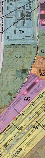
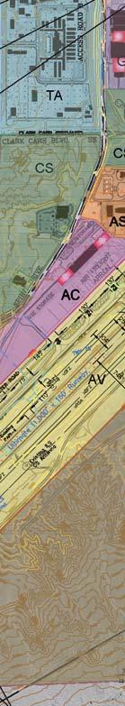
29 Passenger Terminal Area: The passenger terminal area is well defined. It encompasses the terminal building, the vehicle parking structure and surface lots, and the terminal aircraft apron. This designated area includes enough space to accommodate long term growth potential. Airport Support Services Area: This land use designation encompasses the variety of services necessary for operating an airport including the fuel farm, maintenance facilities, the SRE barn, glycol storage, triturater, and other waste collection. General Aviation Area: The general aviation area is also well defined at the Sunport. It includes the FBO facilities, aircraft aprons, and other general aviation support services. Air Cargo Operations Area: The air cargo area is located southwest of the general aviation area. There is a dedicated sort facility and aircraft apron. NON AVIATION/COMMERCIAL SUPPORT This land use classification includes development that is compatible with aviation activities but is unlikely to require access to the runway and taxiway system. Typically, it is preferable that activities in these areas complement airport activities to some degree, but that is not required. Examples of potential uses include research facilities, laboratories, manufacturing and processing facilities, warehouses, and other facilities compatible with an airport environment. As presented previously, there are several parcels owned by the Sunport that have been identified for non aviation development. An in depth analysis of these properties was previously presented and is summarized here. Exhibit 6G graphically presents each of these parcels. Aviation Center of Excellence: With the closure of Runway 17 35, approximately 75 acres of land just northeast of the terminal complex became available for redevelopment. The City of Albuquerque has initiated a project called Destination Sunport to promote the area as an emerging business hub supporting collaboration among Albuquerque s research and development community and the global marketplace. The centerpiece of Destination Sunport is the Aviation Center of Excellence (ACE). ACE is planned to accommodate strategic aerospace and aviation innovations and partnerships. Destination Sunport will also host The Landing, a convenience retail and restaurant development at the north end of the site adjacent to Gibson Boulevard. The City Aviation Department plans on long term ground leases with developers, which provides the benefit of lower upfront capital requirements. The property has direct access to the Sunport s airfield, which will provide tenants with access and connectivity. Commercial uses are strategically located along Gibson Boulevard to serve surrounding communities, as well as ACE workers, Kirtland AFB, and others commuting along Gibson Boulevard. The office/r&d and aviation related development will be located farther south on the property. DRAFT Chapter Six - 29
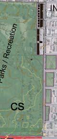
30 The Site Plan for Subdivision for the property was approved in 2014 by the Environmental Planning Commission. Subsequent Site Development Plans for Building Permit for each development project is delegated to the City s Design Review Team (DRT) provided they are consistent with the Site Plan for Subdivision Design Standards. In addition to the City Planning Department s approval process, all buildings, structures, and site plans for projects at the ACE property shall be reviewed and approved by the ACE Architectural Control Committee (ACC). The site plan approval process for the ACE project has been completed. The City Aviation Department can proceed with plans to lease the land to developers. A key component of the Site Plan for Subdivision is the provision for an expedited approval process for future Site Plans for Building Permit through the City s DRT. The planned development includes commercial/retail along Gibson Boulevard, Office/Research and Development in the central portion, and aviation related on the south portion with taxiway access to the airfield. Limited access (right in, right out, left in) is allowed from Gibson Boulevard to the ACE site. Since this development plan is already established, no additional land use alternatives were considered. Puerto del Sol Golf Course: This 72 acre site is located along the north side of Gibson Boulevard. It is currently leased to the City Parks and Recreation Department for use as a municipal golf course. Originally, the golf course was developed as a land use compatible with the runway protection zone for former Runway Now that Runway is closed, there is no longer an RPZ. Therefore, consideration was given to alternative long term plans for the property. The existing zoning for the subject property is SU 1 for Golf Course and Related Facilities. Following review by the Sustainable Master Plan Committee and the public, it is recommended the property remain a public golf course producing revenue to the airport fund. While not currently planned, if the Aviation Department were to consider selling the property, the sale would require FAA approval and all funds generated must go to the Aviation Fund. Sunport Business and Technology Center: This 65 acre site is located to the east of University Boulevard, west of Spirit Drive, and south of Clark Carr Road. It currently has a limited amount of development on the property, including existing airline operations on a five acre leased area and manufacturing on a 1.5 acre leased area. A Master Development Plan was approved by the Environmental Planning Commission for this property in 2008, which was also designated by the City Council as a Foreign Trade Zone. The Master Development Plan showed a north south roadway through the center of the property, but it was situated to the west of center. The lease areas were shown as a series of 17 small one to threeacre lease areas, which limits development on this property particularly considering the topography and grade change from University Boulevard. An updated analysis of the property was conducted as part of this Master Plan and revisions are proposed. The north south internal road is realigned to the east to provide more depth to the lease areas facing University Boulevard due to the topography challenges. As such, development of these lease areas would likely show a low floor area ratio. The internal road provides access to each of the eight proposed lease areas. Land uses include commercial retail, light industrial, and educational. DRAFT Chapter Six - 30


 3 1,000 Landfill Buffer Zone Source: INTERA")
 4 Girard Blvd. Yale Blvd.")

.")

 4 Property north of Airport")


 Property at")
31 ABQ - Sustainable Airport Master Plan NORTH OF AIRPORT LOOP ROAD 4 PROPERTY AND WEST OF GIRARD BLVD. LEGEND Existing Airport Property Line 1 AVIATION CENTER OF EXCELLENCE Ultimate Easement Line Gibson Blvd. SE Yale Landfill Extents Commercial Retail/ Service Area (9.8 acres) 3 1,000 Landfill Buffer Zone Source: INTERA Incorporated; Albuquerque GIS Girard Blvd. SE Runway Protection Zone (RPZ) 4 Girard Blvd. Yale Blvd. University Blvd. Gibson Blvd. Access Taxiway 5 2 SUNPORT BUSINESS AND TECHNOLOGY CENTER Aviation/ Manufacturing Area (40.0 acres) 1 Randolph Rd. G Office/R&D Area (20.6 acres). Rd e 6 rg eo 7 Runway ,793 x 150 Access Road B Ru nw ay , 40 0 PARCELS x x Aviation Center of Excellence 2 Sunport Business and Technology Center 3 Puerto Del Sol Golf Course (to remain) 4 Property north of Airport Loop Road and west of Girard 5 Property located in the northest corner of Sunport Boulevard and University Boulevard (25 acres) nw ay Ru Sp iri td r. 10,0 2 Access Road C University Blvd Property located in the southest corner of Sunport Boulevard and University Boulevard (80 acres) Property at the intersection of George Road and University Boulevard (9 acres) NORTH 0 1,600 SCALE IN FEET Aerial Source: Google Earth 3/9/2014 DRAFT Chapter Six - 31 Exhibit 6G NON-AVIATION LAND USE PLAN
32 DRAFT Chapter Six - 32 This page intentionally left blank
33 A commercial parcel, approximately six acres in size, is located at the northwest corner of the property along Clark Carr Road. It is across the street from the Sunport car rental facility. Due to its proximity, this portion of the property would be a good location for a gas station/convenience store. To the south of the commercial area is a 7.5 acre parcel suggested for educational uses. Visibility and access from University Boulevard are important for this use. Thus, a limited access (right in/rightout/left in) from University Boulevard is shown. To provide this access, retaining walls would be required on both sides of the proposed driveway. The remainder of the site is recommended for light industrial parcels in variety of lease area sizes ranging from five to 10 acres. Property West of ACE: This 12 acre site is located to the south of Miles Road and west of Girard Boulevard. It is to the west of the ACE project and is envisioned as an extension of that project. As airport property, development is subject to applicable FAA regulations. Development of this property will require a Site Development Plan to be approved by the EPC. Depending on whether there is an end user, a Site Plan for Building Permit could either be processed simultaneously with the Site Plan for Subdivision or be submitted as a follow up action later by the end user. Once a Site Plan for Subdivision is approved, delegation of future Site Plans for Building Permit could be requested for delegation to the Development Review Board (DRB) for an expedited approval process. The previous Sunport Master Plan envisioned utilizing this property (and the ACE property) to support a new Sunport terminal building. Since this concept is not being carried through to this Master Plan, a new development alternative is considered. The plan being considered shows one parcel each for office and light industrial uses and maintains the two acre green space which currently contains a multi use trail running north south along the east edge of the property. The office use is located on the northern five acres of the site, across Girard from the existing Airport Business Park. Access to the office area is primarily from Miles Road via Girard Boulevard and is shown to align with Air Park Road. Secondary access to the office area may be available from the existing Columbia Drive. The light industrial area is located on the southern five acres of the site. Secondary access would be available via an extension from the existing Columbia Drive to the south. The extension is currently platted, but it has not been constructed. Property Located in the Northeast Corner of Sunport and University Boulevards: This 25 acre parcel is part of former Yale Landfill ( ) and is located within a designated landfill buffer zone. Future uses on this site that require the least remediation include a solar farm and parking lot. Solar farm projects will require a Glint and Glare Study to assess the feasibility of this use. These uses will need to address the issue of a continuous settling. Mitigation through dynamic compaction has been determined insufficient by the City of Albuquerque Environmental Health Department. All development within the landfill buffer is subject to the City of Albuquerque s Interim Guidelines for development within City designated landfill buffer zones. This requires: DRAFT Chapter Six - 33
34 1) Review of a proposed project by the City s Environmental Health Department Environmental Services Division, 2) Input from a professional engineer with expertise in landfills to determine if landfill gas exists on the property, and 3) If landfill gas is present at the subject property, plans for development must include risk abatement measures which are adequate to address any existing or future risk. These abatement measures must be certified by a professional engineer and signed off on by designated Albuquerque Environmental Health Services Division staff. (See Yale Landfill Development Potential for additional information.) Property Located in the Southeast Corner of Sunport and University Boulevards: This 80 acre parcel is part of former Yale Landfill ( ) and is located within a designated landfill buffer zone. All development within the landfill buffer is subject to the City of Albuquerque s Interim Guidelines for development within City designated landfill buffer zones as described above. Future uses on this site that require the least remediation include a solar farm and parking lot. Solar farm projects will require a Glint and Glare Study to assess the feasibility of this use. These uses will need to address the issue of a continuous ground settlement. Mitigation through dynamic compaction has been determined insufficient by the City of Albuquerque Environmental Health Department. Property Located at the Intersection of George Road and University Boulevard: This 9 acre parcel is located just west of the Yale Landfill and within the Landfill Buffer Zone. Options for future uses on this site are greater than those available for properties located in the northeast and southeast corners of Sunport Boulevard and University Boulevard. However, this site is subject to special City review due to its location within a Landfill Buffer Zone. Through normal decomposition of buried refuse in former landfills, landfill gases may be produced as a byproduct. Landfill gases may migrate to offsite areas surrounding a landfill. As a result, this property will require special consideration of any impact from the former Yale Landfill. The original site will be reduced by the relocated RPZ resulting from moving the Runway 8 landing threshold farther west. Future uses on this site could accommodate a travel center. A detention pond on the northern triangular portion of the property is needed for stormwater purposes. SUSTAINABILITY PERFORMANCE TARGETS For the City of Albuquerque Aviation Department to better gauge and measure its sustainability performance and to drive progress towards achieving the identified sustainability goals and objectives, it is necessary to identify quantifiable performance targets. Multiple performance targets, which are tied to the planning horizons of this Master Plan, have been identified for each resource category. Establishment of these performance targets is based upon numerous sources including trends and conditions DRAFT Chapter Six - 34
35 identified in the baseline assessment, the Sunport Sustainable Management System Reference document, the Energy Audit Report, the CABQ Aviation Department Water Use Report and Conservation Plan Update, as well as industry wide sustainability efforts including environmental goals set by the Airports Council International North America 1 (ACI NA), of which the Sunport is a member. Key performance indicators (KPIs) are the specific, results based, metrics that allow the Aviation Department to gauge sustainability performance and progress towards overall goals. If KPIs are trending positively towards the overall goal, this indicates the specific initiatives that have been put into place are producing desired results; however, if KPIs trend negatively, then this is an indication that the Aviation Department needs to refocus on that specific area and identify opportunities for improvement. Most KPIs should be tracked on a regular (monthly/yearly) basis so that trends can be identified regarding program performance. Sustainability performance targets and KPIs are outlined in Table 6A. The primary intent of this effort is to set targets that are realistic and achievable, but still push the Aviation Department to make significant strides toward improving the sustainability performance of the Sunport. Summaries for each resource category are provided below. WASTE MANAGEMENT AND RECYCLING The Aviation Department s existing waste handling program includes recycling of paper, plastic, and aluminum cans/bottles and regular solid waste removal as well as green waste removal from landscaped areas. The recycling program is focused primarily on the passenger terminal building where stainless steel recycling bins are co located with solid waste bins. The Aviation Department is already planning a terminal improvement project to replace all solid waste and recycle bins with single stations for solid waste and recycling that will result in fewer receptacles but better coverage. Once these new stations are in place, the Aviation Department should conduct waste audits at least every two years to measure the performance of their recycling programs. A waste audit can be a simple examination of waste service provider invoices, which report removed solid waste and recycled material weights. A more detailed waste audit can also be performed to give more specific data on what recyclable materials are being generated in the various areas of the Sunport as well as amounts of recyclable or compostable materials that are not being diverted from the landfill. For this more detailed audit, a collaboration with a local educational facility such as the University of New Mexico could be established to use the waste audit process as an educational tool for students. 1 For more information on ACI NA Environmental Goals visit: na.org/sites/default/files/environmental_goals 1_pager.pdf DRAFT Chapter Six - 35
36 TABLE 6A Sustainability Performance Targets Albuquerque International Sunport Goal 1. Expand the Sunport s existing waste management program to divert more waste from landfills through increased recycling, composting, and procurement policies. Targets Key Performance Indicators Conduct biennial waste audits. Weight (tons) of recycled materials/solid 100% participation by airlines in recycling program by waste/composted materials 100% participation by terminal food concessions in food waste composting by Number of airlines participating in recycling program Number of food concessions participating in food waste composting program Goal 2. Expand energy efficiency measures and renewable energy opportunities. Targets Key Performance Indicators Incorporate all recommended energy efficiency measures (EEMs) by Energy use (kwhs)/month On site energy generation (kwhs)/month Retrofit rental car photovoltaic (PV) system by Energy costs ($)/month Construct credit card parking lot PV system by Expand PV capacity to achieve net zero energy use for all Aviation Department facilities (100% on site renewables) by Goal 3. Commit to the betterment of regional air quality by supporting efforts to reduce greenhouse gas emissions from Sunport users and enacting policies to reduce emissions from Aviation Department controlled sources. Targets Key Performance Indicators Prepare annual greenhouse gas (GHG) emissions reports. GHG emissions/year Achieve carbon neutral growth from 2020 emissions levels for airportcontrolled % of low/no emission equipment sources. Number of alternative fuel/low emission Transition to all electric ground support equipment (GSE) by fleet vehicles Transition to 100% alternative fuel/low emission fleet vehicles by Fuel usage by GSE and fleet vehicles/month Goal 4. Reduce potable water consumption throughout the Sunport with expanded efficiency measures and reclaimed/grey water use. Targets Key Performance Indicators Replace all outdated fixtures in Aviation Department controlled facilities Water use/month (per passenger) by Reclaimed/grey water use/month Install sub metering for all concessionaires, cooling equipment, restrooms, Water costs/month (per passenger) and irrigation on mixed use meters by Number of sub meters installed Utilize 100% reclaimed/grey water for all landscape irrigation by Reduce average indoor water use per passenger from 2014 levels by 50 percent by 2030 (1.0 gallons per passenger) Goal 5. Promote the utilization and expansion of alternative transportation modes to and from the Sunport. Targets Key Performance Indicators Conduct annual surveys of Aviation Department, Sunport tenant employees, Annual employee/passenger survey results and passengers to identify travel modes. Number of EV stations available Install electric vehicle (EV) charging stations in the public parking areas by Number of priority parking spaces for carpools and alternatively fueled vehicles Implement priority parking spaces for carpools and alternatively fueled vehicles by Alternative fuel usage/month Install on site end of trip bicycle facilities for employees by Construct alternative refueling station by Goal 6. Incorporate procurement and construction policies to prioritize the use of more sustainable resources. Targets Key Performance Indicators Establish a Green Procurement Program by Annual expenditures on purchases of sustainable Implement a Green Concessions Policy by and/or locally sourced materials. Implement construction policy by 2020 to commit to LEED or equivalent design standards for all new major construction or renovation projects Number of concessionaires committed to the Green Concessions Policy when applicable. Number of construction/renovation projects that include sustainable elements. DRAFT Chapter Six - 36
37 The Sunport is currently served by eight airlines, of which only Southwest Airlines participates in the Sunport s recycling program. Deplaned waste can be a significant source of solid waste and for this reason, a performance target has been set to engage the airlines and achieve 100 percent participation in recycling by An on site composting facility processes green waste removed from landscaped areas of the Sunport. Composting uses aerobic decomposition to degrade organic material, resulting in a product that can be used as a soil enhancer. Food waste, another significant source of waste and contributor towards greenhouse gas emissions, needs to be targeted for landfill diversion by expanding composting efforts to include food waste from terminal food service providers. Black Mesa Coffee Company has already expressed interest in composting its used coffee grounds. Other airports that have implemented food waste composting programs have dramatically increased solid waste diversion from landfills. Therefore, a performance target has been set to achieve 100 percent participation by terminal food service providers in a food waste composting program by ENERGY The Energy Audit Report (Appendix E) prepared by Quest Energy Group outlined various energy efficiency measures and renewable energy expansion opportunities for the Sunport. The recommended energy efficiency measures (EEMs) include: Installing new condensing boilers (current project) Replacing airfield lighting with LED fixtures Implementing lighting retrofit opportunities throughout the Sunport Controls optimization for HVAC systems High efficiency HVAC filters Data center efficiency updates Install external shading devices or window films for the terminal s south and west facing windows to improve thermal comfort and to save energy. The first performance target for the energy category is to implement each of these EEMs by Beyond the EEMs, the Sunport can take advantage of its existing on site renewable energy centers and expand upon them. The current photovoltaic (PV) systems at the Sunport generate approximately 2,480,000 kilowatt hours (kwh) of energy each year. The Energy Audit Report outlines several expansion opportunities that would help the Sunport achieve net zero energy use. The expansion opportunities described below will serve as additional performance targets for the Sunport. Retrofit rental car photovoltaic (PV) system by 2025 expands total Sunport PV generation by 12 percent (294,800 kwhs) Construct credit card parking lot PV system by 2030 expands total Sunport PV generation by 67 percent (1.9 million kwhs). DRAFT Chapter Six - 37
 The site under consideration for the 8.5 million kwh expansion is the property located in the northeast corner of Sunport and University Boulevards shown in the aerial photo below.")
38 Expand PV capacity to achieve net zero energy use for all Aviation Department facilities (100% on site renewables) by 2035 expands Sunport PV generation by 180 percent (8.5 million kwhs) The site under consideration for the 8.5 million kwh expansion is the property located in the northeast corner of Sunport and University Boulevards shown in the aerial photo below. This site is part of the former Yale Landfill ( ), which has designated a solar farm as a use that would require the least amount of remediation. Any new on site solar expansion projects undertaken at the Sunport will require a Glint and Glare Study to assess the feasibility of the site to ensure the PV systems do not create reflectivity and communication systems interferences. AIR QUALITY AND GREENHOUSE GAS (GHG) EMISSIONS Potential Solar Farm Expansion Site (8.5 million kwh) As detailed in the baseline assessment, GHG emissions at the Sunport come from a variety of sources, many of which are outside the direct control of the Aviation Department. As a result, the performance targets are focused on those sources (Scope 1 sources: Aviation Department fleet vehicles and building energy use) under direct control of the Aviation Department. The first target is to continue to prepare annual GHG emission reports, which the Aviation Department began preparing in recent years. These annual reports should identify the various sources and levels of GHG emissions so that trends can be established. The second performance target is a directive from the ACI NA Environmental Goals for member airports. These goals were originally developed in 2008 and were updated and approved by the ACI NA Board of Directors at the 2015 Annual Conference & Exhibition. The specific goal set forth by ACI NA is for member airports to implement a GHG reduction management program/plan to achieve carbon neutral growth from 2020 emissions levels for airport controlled sources. Therefore, this goal has been adopted as a performance target for the Sunport. The Aviation Department has already taken advantage of the FAA s Voluntary Airport Low Emission (VALE) grant program, which provides AIP grant funding to airports located in non attainment areas for criteria pollutants for projects such as replacing high emitting equipment or vehicles with low emission equipment or vehicles. VALE funding at the Sunport has gone towards acquiring an all electric Chevy Volt fleet vehicle along with a charging station for that vehicle and the installation of the Sunport s PV systems. Additional projects undertaken by the Sunport to improve air quality include the installation of all electric auxiliary power units (APUs), and the Sunport is currently considering a VALE project to implement solar hot water heaters for the terminal building. To build from these efforts, the remaining DRAFT Chapter Six - 38

39 performance targets for this category are to transition to all electric ground support equipment (GSE) by 2025 and to transition to 100 percent alternative fuel/low emission fleet vehicles by Electric Ground Support Equipment and Charging Stations at Seattle Tacoma International Airport Source: Due to improvements in air quality in Bernalillo County, it is possible that the Sunport may no longer qualify for VALE grant funding in the future. Therefore, the Aviation Department should take maximum advantage of this program while it remains qualified. The Aviation Department may also take advantage of the FAA s Zero Emissions Airport Vehicle (ZEV) grant program, which also distributes funds for projects that improve air quality and reduce GHG emissions. WATER CONSERVATION AND WATER QUALITY The performance targets for the water conservation and water quality resource category were derived primarily from the Water Use Report and Conservation Plan (Appendix D). The City of Albuquerque adopted a water conservation ordinance in 1995 intended to reduce water use by large water users such as the Sunport. As a result, the Aviation Department has already undergone renovations to restroom facilities throughout the terminal to install low flow fixtures. The first performance target aims to continue that effort and replace all outdated fixtures in Aviation Department controlled facilities by According to the Water Use Report and Conservation Plan, restroom fixtures (toilets, faucets, showers and urinals) in the terminal and all other Aviation Department buildings that need to be upgraded include 446 fixtures. This upgrade effort should also target kitchen use facilities in the terminal, which can convert conventional equipment to high efficiency equipment including dishwashers, steamers, ice makers, and ice cream wells. Understanding where water use is occurring is vital to understanding and developing strategies to reduce water consumption. For this reason, sub metering of Aviation Department facilities, most notably the terminal building, should be a priority. Installing sub meters at the terminal for all concessionaires and tenants by 2025 and monitoring them will help the Aviation Department better understand where water is consumed and aid in targeting large water users. Furthermore, there are several mixed use meters at DRAFT Chapter Six - 39
 of water for landscape irrigation, which accounted for approximately 86 percent of all Sunport water consumption in 2014.")

40 the Sunport that are both building and irrigation use. Separating these uses with sub meters will again help the Aviation Department categorize its water use areas. The Sunport consumed approximately 51.7 million gallons (mg) of water for landscape irrigation, which accounted for approximately 86 percent of all Sunport water consumption in Improvements have been made to landscaped areas to reduce irrigation water use; however, additional progress can still be made. A reclaimed water line is currently located next to or within 500 feet of most irrigation meters at the Sunport. To utilize this reclaimed water at the Sunport, a booster pump is needed to increase the water line pressure making it suitable for irrigation use. In addition to the reduction of potable water use for irrigation, reclaimed water is charged at a rate of 80 percent of the potable water rate (not including fixed monthly charges), so transitioning to reclaimed water use for irrigation would result in a significant cost savings for the Aviation Department as well. Therefore, a performance target has been set to utilize 100 percent reclaimed water for all landscape irrigation by City of Burbank Recycled Water Use Signage Source: u s faceanother dry year world water day n With the installation of low flow fixtures and improved sub metering, the Sunport should set a performance target to reduce terminal potable water use per passenger by 50 percent below 2014 levels by In 2014, the terminal consumed 1.99 gallons of potable water per passenger (gpp). This performance target aims to achieve 1.00 gpp by Achieving this target should be within reach with the incorporation of the proposed efficiency measures and sub metering efforts. SURFACE TRANSPORTATION Surface transportation is one of the more difficult resource categories to affect change since passengers traveling with luggage are likely to choose the most convenient transportation mode, personal vehicles, over less convenient transportation modes such as public transportation, bicycles, or walking. The first performance target for this resource category is to implement annual passenger and employee surveys to establish travel mode trends. This survey effort can be incorporated into passenger and employee satisfaction surveys to develop a better understanding of how visitors view their overall Sunport experience. Additional performance targets developed for this resource category are focused on providing facilities and equipment that might incentivize alternative transportation use. By 2020, the Sunport should undergo projects to install electric vehicle (EV) charging stations in premium locations that are free for DRAFT Chapter Six - 40

41 public use, and designate priority parking spaces in premium locations for carpools and other alternatively fueled vehicles. By 2025, the Sunport should construct on site, end of trip bicycle facilities for Sunport employee use. These facilities can include lockers, showers, and bicycle storage facilities. Finally, by 2035, the Sunport should coordinate with on site travel centers to incorporate alternative fuel options such as compressed natural gas (CNG), biodiesel, EV stations, hydrogen, liquefied natural gas (LNG), and other emerging technologies as they become available and mass marketed. Electric Vehicle Charging Station at John F. Kennedy International Airport Source: electricvehicle charging stations.html NATURAL RESOURCE MANAGEMENT The focus of the natural resource management resource category is on incorporating new Aviation Department policies and processes to efficiently utilize materials and resources consumed at the Sunport. The Sunport s Sustainable Management System Reference Document (Appendix C) has laid out numerous improvements to address resource conservation, and those action items that have not yet been incorporated have been made into performance targets. By 2020, the Sunport should work to implement a green procurement program and a green concessions policy. The procurement program should set priorities for purchasing materials with recycled content, locally sourced materials, as well as Energy Star certified equipment when possible. A green concessions policy will provide concessionaires with guidance and standards for minimizing waste, enhancing recycling, generating demand for eco friendly products, and providing healthier foods for passengers and employees such as Fair Trade Certified or United States Department of Agriculture (USDA) Certified Organic food products 2. Construction policies should also be put in place by 2020, committing the Aviation Department to design and build any major construction or renovation projects to Leadership in Energy and Environmental Design (LEED) or equivalent standards. This commitment will produce more sustainable components and techniques resulting in smaller environmental footprints. 2 For more information on Fair Trade Certified foods, visit: is fair trade. For more information on USDA Certified Organic food, visit: agriculture.html DRAFT Chapter Six - 41

42 LEED Resource Categories Source: inc.com/blog/how leed certification can be even so much better for green building/ SUMMARY The recommended master plan concept presents a long term vision for the Sunport. The major elements of that vision include mitigating for the airfield hot spots, identification of airfield pavement that may be considered excess, mitigation of taxiway geometry issues, extension of concourse B of the terminal building, future expansion of the air cargo apron and building, and hangar development in the general aviation area. This recommended master plan concept documents a change in direction for the Sunport. The previous Master Plan was completed at a time when forecast growth was significantly higher. Resulting from the trends at the time, a major expansion of the terminal building was in the plan. Since that time, aviation demand, as measured in enplanements, declined significantly until Current trends show a return to growth; however, the new forecasts indicate that the existing terminal building can accommodate that growth with lesser improvements. As a result, the previous plan to utilize the space created by the closure of Runway for a new terminal facility has been replaced with a plan to develop that property. Now that a recommended master plan alternative has been developed, the next chapter will present a capital improvement program (CIP) and identify estimated costs and potential funding sources. DRAFT Chapter Six - 42
MASTER PLAN CONCEPT 1 DRAFT
 The Airport Master Plan Update for Dallas Executive Airport has included the development of aviation demand forecasts, an assessment of future facility needs, and the evaluation of airport development
CHAPTER FOUR AIRPORT ALTERNATIVES
 4.0 INTRODUCTION CHAPTER FOUR The goal of the master planning process is to provide the City of New Smyrna Beach with an assessment of the adequacy and capabilities of the Airport as well as to identify
CHAPTER 3 ALTERNATIVES CONSIDERED
 CHAPTER 3 ALTERNATIVES CONSIDERED 3.0 ALTERNATIVES The 2010 Stevensville Airport Master Plan contained five (5) airside development options designed to meet projected demands. Each of the options from
1) Rescind the MOD (must meet the standard); 2) Issue a new MOD which reaffirms the intent of the previous MOD; 3) Issue a new MOD with revisions.
 Rescind the MOD (must meet the standard); 2) Issue a new MOD which reaffirms the intent of the previous MOD; 3) Issue a new MOD with revisions.") ALBUQUERQUE INTERNATIONAL SUNPORT AIRCRAFT HOLD LINE LOCATION ANALYSIS WHITE PAPER JUNE 24, 2016 HOLD LINE LOCATION ISSUE The location of many of the taxiway hold lines at the Sunport do not meet current
ALBUQUERQUE INTERNATIONAL SUNPORT AIRCRAFT HOLD LINE LOCATION ANALYSIS WHITE PAPER JUNE 24, 2016 HOLD LINE LOCATION ISSUE The location of many of the taxiway hold lines at the Sunport do not meet current
Table of Contents. List of Tables. Cincinnati/Northern Kentucky International Airport 2035 Master Plan Update
 Table of Contents 7.1. Airport Layout Plan (Existing Conditions)... 2 7.2. Airport Layout Plan (Future Conditions)... 3 7.3. Technical Data Sheet... 5 7.4. Commercial Terminal Area Drawing... 5 7.5. East
Appendix 6.1: Hazard Worksheet
 Appendix 6.1: Appendix 6.1: Ref. Condition, real or potential; that can cause injury, illness, etc. This is a prerequisite for an Airfield Hazards 1. Taxiway Geometry Direct access to runway from ramp
Addendum - Airport Development Alternatives (Chapter 6)
") Bowers Field Addendum - Airport Development Alternatives (Chapter 6) This addendum to the Airport Development Alternatives chapter includes the preferred airside development alternative and the preliminary
Bowers Field Addendum - Airport Development Alternatives (Chapter 6) This addendum to the Airport Development Alternatives chapter includes the preferred airside development alternative and the preliminary
Lake Tahoe Airport Master Plan Public Meeting March 16, 2015
 Lake Tahoe Airport Master Plan Public Meeting March 16, 2015 What is an Airport Master Plan? a comprehensive study of an airport [that] usually describes the short, medium, and long term development plans
CHAPTER 1 EXECUTIVE SUMMARY
 CHAPTER 1 EXECUTIVE SUMMARY 1 1 EXECUTIVE SUMMARY INTRODUCTION William R. Fairchild International Airport (CLM) is located approximately three miles west of the city of Port Angeles, Washington. The airport
DRAFT MASTER PLAN UPDATE
 DRAFT MASTER PLAN UPDATE CHAPTER VI: AIRPORT LAYOUT PLAN NARRATIVE DRAFT REPORT APRIL 2017 PREPARED BY: Table of Contents WESTCHESTER COUNTY AIRPORT 6 AIRPORT LAYOUT PLAN NARRATIVE REPORT... 6-1 6.1 AGIS
CHAPTER 1: INTRODUCTION
 CHAPTER 1: INTRODUCTION Purpose and Scope The information presented in this report represents the study findings for the 2016 Ronan Airport Master Plan prepared for the City of Ronan and Lake County, the
Chapter Six ALP Drawings. Tacoma Narrows Airport. Master Plan Update
 Chapter Six ALP Drawings Master Plan Update The master planning process for the (Airport) has evolved through efforts in the previous chapters to analyze future aviation demand, establish airside and landside
Westover Metropolitan Airport Master Plan Update
 Westover Metropolitan Airport Master Plan Update June 2008 INTRODUCTION Westover Metropolitan Airport (CEF) comprises the civilian portion of a joint-use facility located in Chicopee, Massachusetts. The
Dallas Executive Airport
 648 DECLARED DISTANCE OPTION 1a DISPLACE 31 THRESHOLD BY 97 Considers RSA Limiting Factor No runway extensions 13 31 TORA 6,451 6,451 TODA 6,451 6,451 ASDA 5,958 6,451 LDA 5,958 6,354 Runway 17-35 (3,8
FORECASTING FUTURE ACTIVITY
 EXECUTIVE SUMMARY The Eagle County Regional Airport (EGE) is known as a gateway into the heart of the Colorado Rocky Mountains, providing access to some of the nation s top ski resort towns (Vail, Beaver
Tallahassee International Airport Master Plan. Technical Advisory Committee Meeting #2 October 19, 2016
 Tallahassee International Airport Master Plan Technical Advisory Committee Meeting #2 October 19, 2016 Agenda Welcome / Introductions Master Plan Process and Project Status Forecast of Aviation Demand
Lake Tahoe Airport Master Plan
 Lake Tahoe Airport Master Plan City Council Briefing October 20, 2015 What is an Airport Master Plan? a comprehensive study of an airport [that] usually describes the short, medium, and long term development
Grants Pass Airport Master Plan & Airport Layout Plan Update
 Attendees: Grants Pass Airport Master Plan & Airport Layout Plan Update Meeting #3 January 26, 2010 Merlin Community Center 100 Acorn Street, Merlin 5:45 7:15 p.m. Josephine County Department of Airports:
Executive Summary. MASTER PLAN UPDATE Fort Collins-Loveland Municipal Airport
 Executive Summary MASTER PLAN UPDATE Fort Collins-Loveland Municipal Airport As a general aviation and commercial service airport, Fort Collins- Loveland Municipal Airport serves as an important niche
Appendix C AIRPORT LAYOUT PLANS
 Appendix C AIRPORT LAYOUT PLANS Appendix C AIRPORT LAYOUT PLANS Airport Master Plan Santa Barbara Airport As part of this Airport Master Plan, the Federal Aviation Administration (FAA) requires the development
Appendix D Airfield Ongoing Projects Alternatives
 Appendix D Appendix D D.1 Introduction The set of alternatives for each of the airfield facilities was compared with respect to each other and the existing condition. 1 The screening and evaluation process
Chapter 8.0 Implementation Plan
 Chapter 8.0 Implementation Plan 8.1 Introduction This chapter is the culmination of the analytical work accomplished in the previous chapters. The result is a prioritized list of the essential projects.
Lopez Island Airport Master Plan Update. Public Meeting June 15, 2017
 Lopez Island Airport Master Plan Update Public Meeting June 15, 2017 Master Plan Update Team Reid Middleton/Everett, WA Shannon Kinsella, Project Manager Melania Haagsma, Project Engineer Mead & Hunt/Tulsa,
Yolo County Airport. ALP Narrative Report. April Prepared by Mead & Hunt, Inc. for the County of Yolo, California
 Yolo County Airport ALP Narrative Report April 2016 Prepared by Mead & Hunt, Inc. for the County of Yolo, California Yolo County Airport ALP Narrative Report Prepared for the County of Yolo Mindi Nunes,
Chapter 4.0 Alternatives Analysis
 Chapter 4.0 Alternatives Analysis Chapter 1 accumulated the baseline of existing airport data, Chapter 2 presented the outlook for the future in terms of operational activity, Chapter 3 defined the facilities
Appendix D Project Newsletters. Tacoma Narrows Airport. Master Plan Update
 Appendix D Project Newsletters Tacoma Narrows Airport Master Plan Update This appendix contains the newsletters distributed throughout the project. These newsletters provided updates and information on
Draft Concept Alternatives Analysis for the Inaugural Airport Program September 2005
 Draft Concept Alternatives Analysis for the Inaugural Airport Program September 2005 Section 3 - Refinement of the Ultimate Airfield Concept Using the Base Concept identified in Section 2, IDOT re-examined
Draft Concept Alternatives Analysis for the Inaugural Airport Program September 2005
 Section 10 Preferred Inaugural Airport Concept 10.0 Introduction The Preferred Inaugural Airport Concept for SSA was developed by adding the preferred support/ancillary facilities selected in Section 9
Airport Master Plan. Rapid City Regional Airport. October 2015 FAA Submittal
 Airport Master Plan Rapid City Regional Airport October 2015 FAA Submittal Rapid City Regional Airport Master Plan Update Table of Contents Executive Summary... i Scope & Timeline... i Forecasts... i Preferred
1.0 Project Background Mission Statement and Goals Objectives of this Sustainable Master Plan
 TABLE OF CONTENTS CHAPTER 1 INTRODUCTION 10 Project Background 1-1 11 Mission Statement and Goals 1-1 12 Objectives of this Sustainable Master Plan 1-2 CHAPTER 2 INVENTORY 20 Airport Background 2-1 201
Summary of Committee Discussion/Questions Metropolitan Transportation Services Senior Planner Russ Owen presented this item.
 Committee Report Business Item No. 2017-191 Transportation Committee For the Metropolitan Council meeting of September 13, 2017 Subject: Final Crystal Airport 2035 Long Term Comprehensive Plan (LTCP) Proposed
Chapter 4 Airport Facility Requirements
 Chapter 4 Airport Facility Requirements Introduction CHAPTER 4 AIRPORT FACILITY REQUIREMENTS MAY 2013-1 Organization of Materials CHAPTER 4 AIRPORT FACILITY REQUIREMENTS MAY 2013-2 RPZ - ROAD RPZ - NON-AIRPORT
Preliminary Findings of Proposed Alternative
 Preliminary Findings of Proposed Alternative The attached drawing provides a schematic layout of the proposed alternative that will be discussed on July 27, 2010. A full report will follow and should be
Safety, Infrastructure, and Tenant Improvement Project. Public Hearing Informational Brochure February 26, 2013
 New York State Department of Transportation Safety, Infrastructure, and Tenant Improvement Project Public Hearing Informational Brochure February 26, 2013 This DEIS/Draft EA evaluates the potential impacts
Vista Field Airport. Master Plan Update. February, Prepared for: Port of Kennewick One Clover Island Kennewick, Washington
 Vista Field Airport February, 2006 Prepared for: Port of Kennewick One Clover Island Kennewick, Washington 99336 Prepared by: J-U-B ENGINEERS, Inc. 2810 W. Clearwater Avenue, Suite 201 Kennewick, Washington
AIRPORT MASTER PLAN UPDATE
 AIRPORT MASTER PLAN UPDATE PENSACOLA INTERNATIONAL AIRPORT Technical Advisory Committee Meeting #2 June 20, 2017 Agenda» Introduction» Facility Requirements Airside Terminal Landside General Aviation Cargo
Financial Plan/Capital Improvements - DRAFT 6-1
 The analyses completed in previous chapters evaluated development needs at McKinney National Airport (TKI or Airport) over the next 20 years, based on forecast activity, facility requirements, safety standards,
Chapter 4 AIRPORT DEVELOPMENT ALTERNATIVES
 Chapter 4 AIRPORT DEVELOPMENT ALTERNATIVES Chapter Four Airport Development Alternatives Prior to formulating a development program for Ryan Airfield, it is important to consider development potential
CHAPTER 5: Landside Facility Requirements and Development Concepts
 CHAPTER 5: Landside Facility Requirements and Development Concepts Overview Implementation of the preferred intermediate-term (10-year) and long-term (20-year) airside alternatives will have a significant
chapter 5 Recommended Master Plan Concept airport master plan MASTER PLAN CONCEPT
 chapter 5 Recommended Master Plan Concept airport master plan The planning process for Coolidge Municipal Airport has included several analytical efforts in the previous chapters intended to project potential
Source: Chippewa Valley Regional Airport ASOS, Period of Record
 Chapter 1 Inventory Runway wind coverage is the percentage of time a runway can be used without exceeding allowable crosswind velocities. Allowable crosswind velocities vary depending on aircraft size
II. Purpose and Need. 2.1 Background
 II. 2.1 Background The Metropolitan Washington Airports Authority is preparing an Environmental Assessment of potential environmental impacts associated with proposed enhancements to the Runway 4-22 and
Airport Master Plan. Brookings Regional Airport. Runway Runway 17-35
 Runway 17-35 Airport Master Plan Runway 12-30 Brookings Regional Airport Table of Contents Table of Contents Chapter 1: Master Plan Goals... 1-1 1.1. Introduction... 1 1.2. Objective 1 Identify improvements
DEVELOPMENT OF TOE MIDFIELD TERMINAL IROJECT CAPACITY ENHANCEMENT REPORT DEPARTMENT OF AVIATION TOM FOERSTER CHAIRMAN BARBARA HAFER COMMISSIONER
 PETE FLAHERTY COMMISSIONER TOM FOERSTER CHAIRMAN DEPARTMENT OF AVIATION BARBARA HAFER COMMISSIONER STEPHEN A. GEORGE DIRECTOR ROOM M 134, TERMINAL BUILDING GREATER PITTSBURGH INTERNATIONAL AIRPORT PITTSBURGH,
Punta Gorda Airport Master Plan Update
 Punta Gorda Airport Master Plan Update Draft Executive Summary Prepared for: The Charlotte County Airport Authority January 2018 Charlotte County Airport Authority James Herston, Chair Robert D. Hancik,
TABLE OF CONTENTS. General Study Objectives Public Involvement Issues to Be Resolved
 TABLE OF CONTENTS Description Page Number LIST OF ACRONYMS... a CHAPTER ONE INTRODUCTION General... 1-1 Study Objectives... 1-1 Public Involvement... 1-2 Issues to Be Resolved... 1-2 CHAPTER TWO EXISTING
Norfolk International Airport
 Norfolk International Airport Master Plan Update Technical Advisory Committee Meeting #1 Community Advisory Committee Meeting #1 January 24, 2018 Agenda Project Background Introductions Overview of Airport
CHAPTER 3 FACILITY REQUIREMENTS
 CHAPTER 3 FACILITY REQUIREMENTS 3.1 INTRODUCTION To properly plan for the future requirements of Newport News/Williamsburg International Airport, it is necessary to translate the forecasts of aviation
STUDY OVERVIEW MASTER PLAN GOALS AND OBJECTIVES
 INTRODUCTION An Airport Master Plan provides an evalua on of the airport s avia on demand and an overview of the systema c airport development that will best meet those demands. The Master Plan establishes
Public Information Meeting. September 2015
 W ki P O & T / Working Papers One & Two/ Public Information Meeting September 2015 Agenda Introductions and Opening Comments Project Overview, Process, and Schedule Review Materials from Working Papers
SECTION 5 ALTERNATIVE DEVELOPMENT CONCEPT ANALYSES
 SECTION 5 ALTERNATIVE DEVELOPMENT CONCEPT ANALYSES 5.1 INTRODUCTION This section investigates Airfield Development Alternatives, generalized Land Use Alternatives, and more detailed General Aviation Alternatives.
JOSLIN FIELD, MAGIC VALLEY REGIONAL AIRPORT DECEMBER 2012
 1. Introduction The Federal Aviation Administration (FAA) recommends that airport master plans be updated every 5 years or as necessary to keep them current. The Master Plan for Joslin Field, Magic Valley
DRAFT FINAL REPORT AIRPORT MASTER PLAN. Rifle Garfield County Airport Revised May 15, 2014
 DRAFT FINAL REPORT AIRPORT MASTER PLAN Rifle Garfield County Airport Revised May 15, 2014 As required by Paragraph 425.B(4) of FAA Order 5100.38C, Airport Improvement Program (AIP) Handbook: The preparation
STUDY WORK GROUP MEETING No. 4. July 12, 2017
 STUDY WORK GROUP MEETING No. 4 July 12, 2017 Agenda Welcome and introductions Update of project schedule Brief overview of previous SWG meeting Introduction to airport development alternatives Comments,
October 2014 BELLINGHAM INTERNATIONAL AIRPORT MASTER PLAN PRESENTATION
 October 2014 BELLINGHAM INTERNATIONAL AIRPORT MASTER PLAN PRESENTATION The Master Plan Process Inventory Of Existing Conditions Complete. Forecasts Of Aviation Demand Complete. Facility Requirements Complete.
Draft Concept Alternatives Analysis for the Inaugural Airport Program September 2005
 Draft Concept Alternatives Analysis for the Inaugural Airport Program September 2005 Section 1 - Introduction This report describes the development and analysis of concept alternatives that would accommodate
STAFF REPORT. Airport Land Use Plan Consistency Review: Santa Barbara Airport Master Plan. MEETING DATE: November 19, 2015 AGENDA ITEM: 7D
 STAFF REPORT SUBJECT: Airport Land Use Plan Consistency Review: Santa Barbara Airport Master Plan MEETING DATE: AGENDA ITEM: 7D STAFF CONTACT: Peter Imhof, Andrew Orfila RECOMMENDATION: Adopt findings
BNA Master Plan Update Community Advisory Committee Meeting No. 5
 A Six Sigma Organization BNA Master Plan Update Community Advisory Committee Meeting No. 5 September 19, 2012 Introductions MNAA Staff RW Armstrong Team Albersman & Armstrong, Ltd. Atkins North America,
Alternatives. Introduction. Range of Alternatives
 Alternatives Introduction Federal environmental regulations concerning the environmental review process require that all reasonable alternatives, which might accomplish the objectives of a proposed project,
PORT OF PORTLAND. Chapter Six AIRPORT PLANS
 PORT OF PORTLAND Chapter Six AIRPORT PLANS CHAPTER SIX PORT OF PORTLAND AIRPORT PLANS The planning process for the Hillsboro Airport Master Plan has included several technical efforts as outlined in the
5.0 ALTERNATIVES ANALYSIS
 5.0 ALTERNATIVES ANALYSIS The Alternative Analysis chapter describes and evaluates the various development alternatives considered for. In addition, it presents a preferred development plan that accommodates
Study Committee Meeting. September 2015
 W ki P T / Working Paper Two/ Study Committee Meeting September 2015 Agenda Introductions and Opening Comments Project Overview, Process, and Schedule Review Materials from Working Paper Two Comments,
PUBLIC NOTICE ***************************** New Castle Airport. Intention to File a Passenger Facility Charge (PFC) Application
 Application") PUBLIC NOTICE ***************************** New Castle Airport Intention to File a Passenger Facility Charge (PFC) Application The Delaware River & Bay Authority (DRBA), the sponsor of the New Castle Airport
PUBLIC NOTICE ***************************** New Castle Airport Intention to File a Passenger Facility Charge (PFC) Application The Delaware River & Bay Authority (DRBA), the sponsor of the New Castle Airport
ACTION TRANSMITTAL
 Transportation Advisory Board of the Metropolitan Council of the Twin Cities ACTION TRANSMITTAL 2018-16 DATE: February 9, 2018 TO: Transportation Advisory Board FROM: Technical Advisory Committee PREPARED
Chapter Seven COST ESTIMATES AND FUNDING A. GENERAL
 Chapter Seven COST ESTIMATES AND FUNDING A. GENERAL This chapter delineates the recommended 2005 2024 Sussex County Airport Capital Improvement Program (CIP). It further identifies probable construction
The purpose of this Demand/Capacity. The airfield configuration for SPG. Methods for determining airport AIRPORT DEMAND CAPACITY. Runway Configuration
 Chapter 4 Page 65 AIRPORT DEMAND CAPACITY The purpose of this Demand/Capacity Analysis is to examine the capability of the Albert Whitted Airport (SPG) to meet the needs of its users. In doing so, this
MASTER PLAN UPDATE. Planning Advisory Committee (PAC) FRESNO YOSEMITE INTERNATIONAL AIRPORT. Meeting #4
 FRESNO YOSEMITE INTERNATIONAL AIRPORT. Meeting #4") MASTER PLAN UPDATE Planning Advisory Committee (PAC) FRESNO YOSEMITE INTERNATIONAL AIRPORT Meeting #4 December 14, 2017 Today s Agenda o Welcome o Introductions o Progress update o Alternatives analysis
MASTER PLAN UPDATE Planning Advisory Committee (PAC) FRESNO YOSEMITE INTERNATIONAL AIRPORT Meeting #4 December 14, 2017 Today s Agenda o Welcome o Introductions o Progress update o Alternatives analysis
Airport Master Plan Open House Front Range Airport February 23, 2017
 Airport Master Plan Open House Front Range Airport February 23, 2017 MASTER PLAN PROCESS AND OVERVIEW MASTER PLAN ELEMENTS The Master Plan is a 20-year plan to understand the needs of current and future
1 DRAFT. General Aviation Terminal Services Aircraft Hangars Aircraft Parking Aprons Airport Support Facilities
 To properly plan for improvements at Dallas Executive Airport, it is necessary to translate forecast aviation demand into the specific types and quantities of facilities that can adequately serve the demand.
IDENTIFICATION AND EVALUATION OF ALTERNATIVES ST. PETERSBURG-CLEARWATER INTERNATIONAL AIRPORT
 IDENTIFICATION AND EVALUATION OF ALTERNATIVES ST. PETERSBURG-CLEARWATER INTERNATIONAL AIRPORT 7 7.1 GENERAL The primary objective of this chapter is to evaluate potential development alternatives and identify
Document prepared by MnDOT Office of Aeronautics and HNTB Corporation. MINNESOTA GO STATE AVIATION SYSTEM PLAN
 LAST UPDATE JULY 2013 Acknowledgements The preparation of this document was financed in part by a grant from the Federal Aviation Administration (Project No: 3-27-0000-07-10), with the financial support
AIRSIDE CAPACITY AND FACILITY REQUIREMENTS
 AIRSIDE CAPACITY AND FACILITY REQUIREMENTS This Section investigates the capacity of the airport, its ability to meet current demand, and the facilities required to meet forecasted needs as established
Airfield Design OVERVIEW BASIC DESIGN FACTORS. Airport Role
 3 Airfield Design OVERVIEW Due to the presence of significant physical constraints, little change to the existing airfield is anticipated. The emphasis in this plan is on identifying airfield improvements
Table of Contents. Overview Objectives Key Issues Process...1-3
 Table of Contents Chapter One Introduction Overview...1-1 Objectives...1-1 Key Issues...1-2 Process...1-3 Chapter Two Inventory of Existing Conditions Airport Setting...2-1 Locale...2-1 Airport Surroundings...2-5
SouthwestFloridaInternational Airport
 SouthwestFloridaInternational Airport SouthwestFloridaInternationalAirportislocatedinLee CountyalongtheGulfCoastofSouthFlorida,tenmiles southeastofthefortmyerscentralbusinessdistrict. Theprimaryhighwayaccesstotheairportfrom
Chapter 2 FINDINGS & CONCLUSIONS
 Chapter 2 FINDINGS & CONCLUSIONS 2.01 GENERAL Dutchess County acquired the airport facility in 1947 by deed from the War Assets Administration. Following the acquisition, several individuals who pursued
Introduction DRAFT March 9, 2017
 Chapter Overview The City of Redmond (City) initiated an update to the Airport Master Plan ( Plan ) to assess the facility and service needs of the Redmond Municipal Airport ( the Airport ) throughout
JUNEAU RUNWAY INCURSION MITIGATION (RIM) PROGRAM JANUARY 25, 2017
 PROGRAM JANUARY 25, 2017") JUNEAU RUNWAY INCURSION MITIGATION (RIM) PROGRAM JANUARY 25, 2017 1 Agenda Program Description Runway Incursions Design and Geometry Deficiencies Runway 8/26 Operations Potential Mitigation Next Steps
JUNEAU RUNWAY INCURSION MITIGATION (RIM) PROGRAM JANUARY 25, 2017 1 Agenda Program Description Runway Incursions Design and Geometry Deficiencies Runway 8/26 Operations Potential Mitigation Next Steps
PORT OF PORTLAND. Chapter Seven CAPITAL IMPROVEMENT PROGRAM
 PORT OF PORTLAND Chapter Seven CAPITAL IMPROVEMENT PROGRAM CHAPTER SEVEN PORT OF PORTLAND CAPITAL IMPROVEMENT PROGRAM The analyses conducted in the previous chapters evaluated airport development needs
Chapter Four ALTERNATIVES
 Chapter Four ALTERNATIVES Master Plan Update This chapter walks through the process of identifying and evaluating development alternatives to serve the (Airport) in the near-term to the distant future.
CHAPTER 2 ALTERNATIVES
 CHAPTER 2 ALTERNATIVES 2.1 ALTERNATIVES INTRODUCTION An Environmental Impact Statement (EIS) describes and discusses the significant environmental impacts that would be caused by the Proposed Action, its
MONTEREY REGIONAL AIRPORT MASTER PLAN TOPICAL QUESTIONS FROM THE PLANNING ADVISORY COMMITTEE AND TOPICAL RESPONSES
 MONTEREY REGIONAL AIRPORT MASTER PLAN TOPICAL QUESTIONS FROM THE PLANNING ADVISORY COMMITTEE AND TOPICAL RESPONSES Recurring topics emerged in some of the comments and questions raised by members of the
Notice and Opportunity to Comment on New Proposed Passenger Facility Charge (PFC) New Application
 New Application") July 3, 2018 Notice and Opportunity to Comment on New Proposed Passenger Facility Charge (PFC) New Application The City of Kansas City (City), Missouri through its Aviation Department ( the Department
July 3, 2018 Notice and Opportunity to Comment on New Proposed Passenger Facility Charge (PFC) New Application The City of Kansas City (City), Missouri through its Aviation Department ( the Department
RECOMMENDED MASTER PLAN CONCEPT
 RECOMMENDED MASTER PLAN CONCEPT Chapter Five The airport master planning process for Salina Regional Airport (SLN) has progressed through a systematic and logical process with a goal of formulating a recommended
3.9 AIRPORT SUPPORT FACILITIES
 3.9 AIRPORT SUPPORT FACILITIES This section details additional airfield facilities that may be required over the next 20 years. 3.9.1 Airport Rescue and Fire Fighting (ARFF) Station GEG is certified under
Chapter 9 - AIRPORT SYSTEM DESIGN
 Chapter 9 - AIRPORT SYSTEM DESIGN 9.01 GENERAL This chapter discusses the development program for Dutchess County Airport to the year 2020. This airport system design is based upon the airport's existing
CHAPTER 4: ALTERNATIVES
 MSP Long Term Comprehensive Plan Update Metropolitan Airports Commission 4.1 INTRODUCTION CHAPTER 4: ALTERNATIVES Several alternatives were developed and evaluated based on their capability to meet the
STUDY WORK GROUP MEETING No. 3. November 29, 2016
 STUDY WORK GROUP MEETING No. 3 November 29, 2016 Agenda Welcome and introductions Update project schedule Brief overview of previous SWG meeting Update on aviation forecasts Introduction to airfield demand/capacity
1.1.3 Taxiways. Figure 1-15: Taxiway Data. DRAFT Inventory TYPICAL PAVEMENT CROSS-SECTION LIGHTING TYPE LENGTH (FEET) WIDTH (FEET) LIGHTING CONDITION
 WIDTH (FEET) LIGHTING CONDITION") 1.1.3 Taxiways EWN has an extensive network of taxiways and taxilanes connecting the terminal, air cargo, and general aviation areas with the runways as listed in Figure 1-15. A 50-foot wide parallel taxiway
1.1.3 Taxiways EWN has an extensive network of taxiways and taxilanes connecting the terminal, air cargo, and general aviation areas with the runways as listed in Figure 1-15. A 50-foot wide parallel taxiway
8.0 AIRPORT LAYOUT PLANS
 8.0 AIRPORT LAYOUT PLANS This chapter presents a detailed graphic and narrative description of the selected development concept for General Mitchell International Airport (MKE). The plans package presented
Chapter Three AIRPORT FACILITY REQUIREMENTS/ALTERNATIVES
 Chapter Three AIRPORT FACILITY REQUIREMENTS/ALTERNATIVES Airport Layout Plan Report In this chapter, existing components of the Airport are evaluated so that the capacities of the overall system are identified.
Agenda: SASP SAC Meeting 3
 Agenda: SASP SAC Meeting 3 Date: 04/12/18 Public Involvement Plan Update Defining the System Recommended Classifications Discussion Break Review current system Outreach what we heard Proposed changes Classification
Current and Forecast Demand
 Existing Facilities Jacksonville International Airport (JIA) is served by a number of airside and landside facilities. There are two runways that serve the airport in an open V configuration. The Annual
CHAPTER 6 ALTERNATIVES ANALYSIS
 CHAPTER 6 ALTERNATIVES ANALYSIS 6 6 ALTERNATIVES ANALYSIS INTRODUCTION The purpose of this chapter is to identify and evaluate alternative development strategies for long-range development planning at
Milton. PeterPrinceAirportislocatedinSantaRosaCounty, approximatelythreemileseastofmilton.
 Milton GeneralAviationAirport PeterPrinceAirportislocatedinSantaRosaCounty, approximatelythreemileseastofmilton. Existing Facilities Peter Prince Airport is served by one runway, Runway 18/36, 3,700 feet
TECHNICAL REPORT #7 Palm Beach International Airport Airport Layout Plan
 TECHNICAL REPORT #7 Palm Beach International Airport Airport Layout Plan Technical Report #7 Palm Beach International Airport Layout Plan Palm Beach International Airport Prepared for Palm Beach County
1 PURPOSE AND NEED 1.1 INTRODUCTION
 1.1 INTRODUCTION 1 PURPOSE AND NEED This Environmental Assessment (EA) addresses projects at Juneau International Airport (JIA) that are the direct outcome of a Master Plan prepared for the airport and
CHAPTER 1 BACKGROUND AND PROPOSED ACTION
 CHAPTER 1 BACKGROUND AND PROPOSED ACTION 1.0 INTRODUCTION An Environmental Assessment (EA) evaluates the effects of a proposed Federal action on the surrounding environment and is prepared in compliance
PROPOSED HORIZONTAL LAYOUT FILLET DESIGN FOR ENTRANCE/EXIT TAXIWAYS
 PROPOSED HORIZONTAL LAYOUT FILLET DESIGN FOR ENTRANCE/EXIT TAXIWAYS INTRODUCTION The Zelienople Airport Authority (ZAA) has commenced engineering activities for the rehabilitation of Runway 17-35 to a
Hartford-Brainard Airport Potential Runway Closure White Paper
 Hartford-Brainard Airport Potential Runway 11-29 Closure White Paper June 2012 In recent years there has been discussion regarding the necessity of Runway 11-29 to the Hartford- Brainard Airport (HFD)