Hartford-Brainard Airport Potential Runway Closure White Paper
|
|
|
- Earl Bradford
- 5 years ago
- Views:
Transcription


1 Hartford-Brainard Airport Potential Runway Closure White Paper June 2012
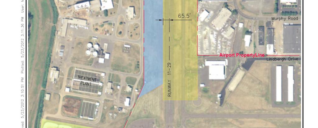
2 In recent years there has been discussion regarding the necessity of Runway to the Hartford- Brainard Airport (HFD) and its potential closure. As part of the recent Master Plan Update (MPU), the potential closure was evaluated. This stand alone document discusses the following topics related to the closure of Runway 11-29: Airport Background User Consultation Wind Coverage Runway Use Airfield Capacity Benefits of Closure Future Use of Property Facility Relocation Summary Airport Background Hartford-Brainard Airport (HFD), owned by the State of Connecticut, is a general aviation (GA) airport located near downtown Hartford, Connecticut. Corporate travel, flight training, recreational flights, and many other aviation activities take place at HFD. Across the airport s 201 acres, there are two paved runways, one turf runway, and two helipads, with parking for over 200 aircraft. Air traffic is controlled by staff in the Air Traffic Control Tower (ATCT) from 6AM to midnight each day. Runway 2-20 is the primary runway and is 4,417 feet long and 150 feet wide. The runway thresholds have been displaced on both ends to meet approach clearance requirements, as the runway is surrounded by the Clark Dike a Connecticut River flood control dike approximately 25 to 30 feet tall. The runway is equipped with High Intensity Runway Lights (HIRL), Visual Glide Slope Indicators (VGSI), and Runway End Identifier Lights (REIL). Runway 2 has two non-precision approaches, a Localizer Directional Aid and a GPS-RNAV approach. The airport also has a VOR approach (circling only) and a published visual approach for noise abatement. The runway markings are non-precision and in good condition. Runway 2-20 serves the vast majority of the needs of the users of HFD. Runway is 2,314 feet long by 71 feet wide and is used exclusively for smaller GA aircraft (Airport Reference Code B-I). The pavement strength allows for regular use by aircraft up to 10,000 pounds. The runway has visual markings, which are in good condition. Runway 29 has a displaced threshold of 265 feet due to the Clark Dike. Runway is served by a full-length, parallel taxiway. User Consultation As part of this study, the airport stakeholders will be consulted. It is proposed that in conjunction with the circulation of the FAA Form, the Sponsor will send a notice to the tenants and the Consultant will send a notice to the Advisory Committee. This notice will ask readers to review this document, and reply to the Form when requested. This document and notice will also be posted to the study website for public review and comment. The website is located at 1
3 Wind Coverage The ideal orientation of a runway is based on a function of wind speed and direction, and the ability of aircraft to operate under crosswind conditions. As a general principle, runways should be oriented as closely as practical to the direction of the prevailing winds. This enables aircraft to take off and land in the direction of the wind, which improves the safety and efficiency of operations. The most ideal runway alignment provides the highest wind coverage percentage. The desired wind coverage for an airport has been set by the FAA at 95 percent. In cases where a single runway cannot provide adequate wind coverage, a crosswind runway may be considered, but is not an FAA requirement. The FAA assumes that small, ARC B-I aircraft can safely handle crosswinds of no greater than 10.5 knots (12 mph), and is referred to as the crosswind component. ARC B-II aircraft can handle crosswinds of up to 13.0 knots (15 mph). The current runway system at HFD with Runway 2-20 (true azimuth 9 degrees) and Runway (true azimuth of 099 degrees) can adequately accommodate both ARC B-I and B-II aircraft (10.5- knots and 13-knots). The wind coverage during both all-weather and poor weather conditions is 99 percent. This information was calculated by the FAA s Airport Design Software using 10 years of recorded wind data from the weather station located at HFD from 2000 to Table 1 Wind Coverage Runway Both 10.5kts 13kts 10.5kts 13kts 10.5kts 13kts All-Weather N/A N/A VFR (good weather) N/A N/A IFR (poor weather) N/A N/A N/A N/A Table 1 also identifies that if Runway were to be closed, HFD would still provide over 95 percent wind coverage with only Runway 2-20, with 95 to 99 percent coverage in all conditions for ARC B-I. Seasonal variations were also reviewed to identify any acute differences between the winter and summer seasons in Connecticut. The month of January has an average high of 36 degrees, with the average high temperature in July of 84 degrees. Table 2 shows the wind coverage based on the season. As is typical, average wind speed is greater in winter, which reduces the wind coverage of the single-runway coverage. However, training and recreational activity by light aircraft is also reduced in winter due to weather conditions. The seasonal evaluation identifies that in January, the 10.5 knot coverage for Runway 2-20 is 94 percent, slightly below the desired level, but can still be considered reasonable. 2
4 Table 2 - Seasonal Wind Coverage Runway Both 10.5kts 13kts 10.5kts 13kts 10.5kts 13kts January All-Weather N/A N/A January IFR N/A N/A N/A N/A July All-Weather N/A N/A July IFR N/A N/A N/A N/A Figure 1 displays the frequency of the wind based on direction. This graph displays the strong dominance of both north and south winds by percentage at HFD, with winds from the northwest as a distant third in frequency. Figure 1 Wind Frequency % % % % % 2% 1% 0% In summary, the wind data analysis determined that if Runway were closed, HFD would be able to operate safely from a wind coverage standpoint (i.e., Runway 2-20 provides 95% all weather wind coverage with a 10.5 knot crosswind component) Runway Use Table 3 displays the expected runway usage based exclusively on the recorded wind data, and demonstrates that Runway would be used 25 percent of the time. However, several other factors affect the runway end of use, mainly runway length. Most twin-engine and corporate aircraft cannot land on Runway due to the reasons discussed in the Airport Master Plan (Section Runway Length) and discussed below. Runway is only 2,314 feet long. Although, light aircraft can often operate from this length, there is little margin for error. 3
5 Insurance underwriters for corporate jets typically prefer a 5,000 foot or greater runway length for safety purposes, and a runway of this length allows aircraft owners to avoid higher premiums or reduced coverage. Aircraft operating under the Federal Aviation Regulations (FAR) Part 135 are more commonly known as charter operations. They are flights that are conducted by a hired pilot, typically for business purposes. Charter operations represent a large share of the activity at HFD. These operators have additional runway length requirements for safety reasons. For example, every corporate jet aircraft has a certain runway length requirement for takeoff, which varies based on the passenger and fuel load and meteorological conditions (i.e. takeoff run distance). When operating under Part 135, the runway must also be long enough for the aircraft to accelerate to takeoff speed, decelerate, and stop prior to the end of the runway (i.e. accelerate to stop distance). This required length is always longer then the takeoff run length. Furthermore, the Clark Dike and trees currently obstruct the landing approach; making the use of the short runway more challenging. Table 3 Predicted Runway Use Based on Recorded Wind Data Runway End Percentage 2 27% 55% 20 28% 11 5% 29 20% Calm 20% Total 100% During calm winds, an aircraft can safely land in any direction. During these conditions, pilots review other factors beyond runway length to determine the ideal landing, such as the displaced thresholds, potential obstructions to the runway, the amount of fuel onboard, and runway conditions. Another consideration is the location of the aircraft s amenities; if an aircraft is parking on the north side of the airport, they will not want to land on Runway 29 and taxi the longer distance when they could land on Runway 2 and exit the runway near their hangar or destination on the Airport. On a daily basis, this reduction in taxing can result in savings for an aircraft owner on fuel expenditures. Table 4 displays the runway usage that typically occurs at HFD on an annual basis based on historical activity. Table 3 shows that 20 percent of wind observations are considered calm. As Runway 2 is designated as the calm wind runway, operations during those conditions utilize Runway 2. This means the Runway 2 end is typically utilized for 57 percent of the annual operations. Table 4 shows that Runway 2-20 is utilized 85 percent of the time, Runway 2-57 percent and Runway percent. Thus, Runway can be expected to be used only 15 percent of the time. If all wind conditions below 10 knots were considered calm, Runway 2-20 would be utilized 94 percent of the time. 25% 4
6 Table 4 Observed Runway Use Runway End Percentage 2 57% 85% 20 28% 15% Total 100% 11 5% 29 10% Based on the wind coverage discussed previously, if Runway were to close, the majority of the operations are that currently estimated to use Runway could safely use Runway Runway 2-20 s width of 150 feet is an added advantage as it will allow for a greater margin of error for pilots of light aircraft during high wind conditions. Airfield Capacity This section reviews the airfield capacity of HFD, evaluates any capacity surpluses or deficiencies, and identifies airfield improvements that may be required during the 20-year planning period. Airfield capacity is defined as the maximum rate that aircraft can arrive at, or depart from, an airfield with an acceptable level of delay. It is a measure of the number of operations that can be accommodated at an airport during a given time period, which is determined based on the available airfield system (runways, taxiways, navaids, etc.) and airport activity characteristics. The current procedure employed by the FAA to evaluate airfield capacity is described in Advisory Circular (AC) 150/5060-5, Airport Capacity and Delay. Annual Service Volume (ASV) A reasonable estimate of the airport s annual maximum capacity, accounting for annual changes in weather, runway use, aircraft fleet mix, and other conditions. Hourly Airfield Capacity The maximum number of aircraft operations that can take place on the runway system in one hour. As airport activity occurs in certain peaks throughout the day, accommodating the peak hour activity is most critical. For airports that have multiple runways, multiple operating procedures can be used (e.g., landing on one runway with departures on another). The AC provides tables of estimated capacity based on specific airport characteristics. For HFD, three capacity scenarios were evaluated: Current Airfield Configuration Elimination of Runway Elimination of Runway and Taxiway J The following characteristics and assumptions were applied to all three scenarios: Operations of aircraft over 12,500 pounds are set at seven percent 1 throughout the forecast period 1 This assumption is based on a review of the forecast data completed as part of airport master plan (Chapter 2). 5
7 No aircraft over 300,000 pounds No scheduled commercial service No airspace limitations Landings generally equal takeoffs during peak periods There are full-length parallel taxiways and ample exit taxiways for each runway No precisions approaches (ILS) are in place The turf runway is not used in the estimation of runway capacity Annual Service Volume (ASV) Table 5 displays the ASV for the three scenarios based on the assumptions described above: ASV is 230,000 flights per year under each scenario. As only one runway can be in operation at a time, the elimination of Runway will not affect the ASV of HFD. As Taxiway J is a dual-parallel taxiway, its elimination will not affect the ASV of HFD. The current airfield configuration currently provides ample capacity to accommodate existing and future operations of 80,000 and 85,600 flights per year, respectively. HFD would still be below 60% of the ASV if the 127,000 annual operations in the potential growth scenario in the airport master plan were to occur; thus, annual capacity is not an issue. Table 5 Annual Service Volume Scenario Forecasted Demand ASV Demand ASV Current Airfield Configuration 230, ,000 Elimination of Runway , ,000 85, ,000 Elimination of Runway , ,000 and Taxiway J Hourly Capacity Table 6 displays the estimated VFR and IFR hourly capacities of HFD based on the assumptions described above. VFR capacity is estimated at 98 flights per hour and IFR capacity is estimated at 59 flights per hour for both 2010 and As only one runway can be in operation at a time, the elimination of Runway will not affect the hourly capacity of HFD. As Taxiway J is a dualparallel taxiway, its elimination will not affect the hourly capacity of HFD. The current airfield configuration currently provides ample capacity to accommodate existing and future operations with peak hour operations of 37 and 39 flights per hour respectively. 6
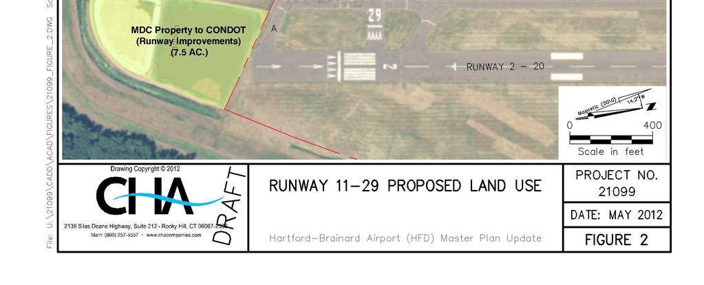
8 Scenario Current Airfield Configuration Elimination of Runway Elimination of Runway and Taxiway J Peak Hour Operations 37 Table 6 Hourly Capacity VFR IFR Peak Hour Capacity Capacity Operations VFR Capacity IFR Capacity Benefits of Closure While Runway does provide a benefit to users, there is also a benefit to closing the runway related to the Metropolitan District Commission (MDC) adjacent waste water processing facility. The MDC has managed the region s water and sewer systems since One of their largest waste water processing facilities is located adjacent to the airport along the southern border. The MDC is moving forward with a one billion dollar investment to improve the area s water quality and protect health and safety of the local community during high water events such as storms. This project will expand the capacity and capabilities of the facility, including upgrading to more modern technologies. Figure 2 shows a concept to reuse approximately 10 acres of the Runway property for MDC facilities. In exchange, the Airport would gain a similar amount of property for Runway 2-20 safety improvements. The main benefit is the ability to provide standard Runway Safety Areas (RSA) and Object Free Areas (ROFA) to Runway Table 7 displays the Federal Aviation Administration (FAA) design standards for Runway 2-20, and the existing deficiency for that standard. Runway Safety Area (RSA) A defined surface surrounding a runway prepared for reducing the risk of damage to aircraft in the event of an undershoot, overshoot, or excursion from the runway. This area must also support snow removal, aircraft rescue, and firefighting equipment. The RSA should be free of objects, except for objects that must be located in the area because of their function. Runway Object Free Area (ROFA) A ground area surrounding runways that should be clear of objects (e.g., roads, buildings, etc.), except for objects that need to be within the area due to their function. Table 7 ARC Airfield Design Standards for Runway 2-20 (ARC B-II) Airfield Facility Existing Requirement Deficit Runway Safety Area (RSA): Length (beyond Runway 2) Width Object Free Area (OFA): Length (beyond Runway 2) Width None
9

10 As shown in Figure 3 and 4, two sewage treatment lagoons owned by the MDC are located beyond the Runway 2 end, approximately 20 feet below the runway elevation, which create a non-standard RSA and OFA. By allowing the MDC to utilize a portion of the Runway property for their operations, they are willing to deed the State of Connecticut the property where the lagoons are located. This property would then be used for improved RSA and OFA for Runway Any necessary environmental remediation of the lagoons will need to be completed prior to the transfer of the property to the State. If the property containing the lagoons cannot be acquired by the CTDOT to provide a standard OFA and RSA on the southern end of the Runway, the runway would have to be physical shortened or declared distances implemented until the standards could be met. Table 8 displays the impact to Runway 2-20 if declared distances were implemented. Specifically, the lagoons will reduce the Accelerate-Stop Distance Available (ASDA) and Landing Distance Available (LDA) for Runway 20 by 300 feet, significantly affecting the ability for the runway to be utilized by corporate aircraft. As HFD serves downtown Hartford, one of its main roles is to provide a safe airport for corporate traffic. Implementing declared distances or physically shortening the runway will severely impact this role. Furthermore, regardless of runway length requirements, existence of the lagoons within the OFA and RSA is a safety concern for all aircraft and all operations at the airport. Table 8 Declared Distances (Feet) Item Runway 2 Runway 20 Takeoff Run Available (TORA) 4,417 4,417 Takeoff Distance Available (TODA) 4,417 4,417 Accelerated-Stop Distance Available (ASDA) 4,017 4,117 Landing Distance Available (LDA) 3,607 3,557 Displaced Threshold Figure 3 Clark Dike and MDC Lagoons 9

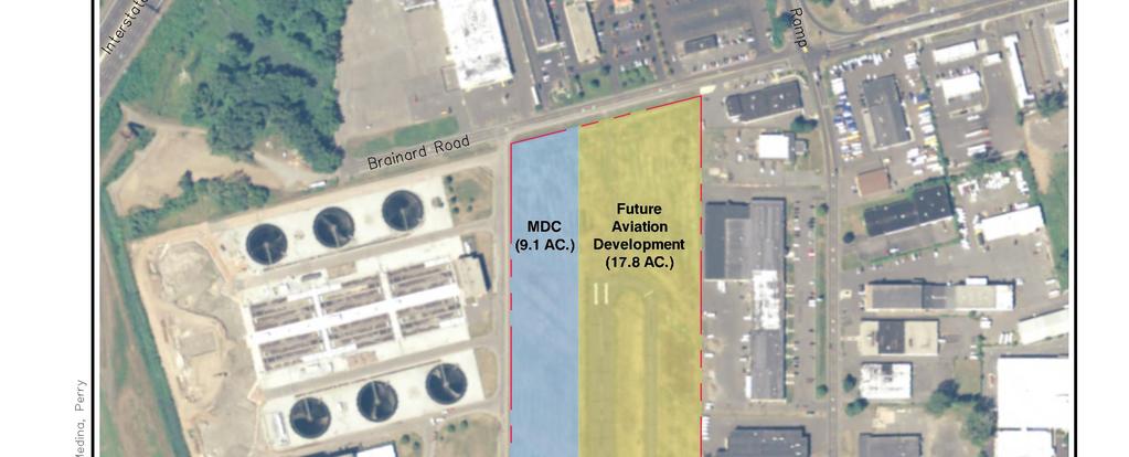
11 OFA Figure 4 Runway 2 Object Free Area Future Use of Property The remaining area of the former Runway property would be reserved for future aircraft storage and associated infrastructure such as a taxiway and taxiway safety areas to access Runway 2-20, aprons, and a vehicle access road. The access road would allow access from both Brainard Road and Lindbergh Drive to the airport. As this property was not acquired using Federal Aviation Administration (FAA) Airport Improvement Program (AIP) funds, the CTDOT is not required to financially reimburse the FAA for the sale or transfer of this property. Additionally, the Runway pavement is towards the end of its useful life as it was last repaved in It is anticipated that the FAA would consider the grant assurances associated with accepting an AIP rehabilitation grant satisfied for this runway. Any funds derived from the sale of the property to MDC would be utilized solely at HFD for future airport projects. Facility Relocation There are currently no facilities that will need to be relocated if Runway is closed. There are no navigational aids or aircraft storage associated with this runway. Runway and taxiway lighting and signage will need to be removed. Summary It is anticipated that the closure of Runway would not adversely impact overall operations at HFD. Runway 2-20 is considered adequate to supply the current and future demand of HFD. Although, the closure would impact light aircraft activity during certain wind conditions (strong westerly winds), the closure could have a net safety benefit by allow for improvements to the Runway 2-20 Safety Area and Object Free Area. 10
According to FAA Advisory Circular 150/5060-5, Airport Capacity and Delay, the elements that affect airfield capacity include:
 4.1 INTRODUCTION The previous chapters have described the existing facilities and provided planning guidelines as well as a forecast of demand for aviation activity at North Perry Airport. The demand/capacity
Preliminary Findings of Proposed Alternative
 Preliminary Findings of Proposed Alternative The attached drawing provides a schematic layout of the proposed alternative that will be discussed on July 27, 2010. A full report will follow and should be
The purpose of this Demand/Capacity. The airfield configuration for SPG. Methods for determining airport AIRPORT DEMAND CAPACITY. Runway Configuration
 Chapter 4 Page 65 AIRPORT DEMAND CAPACITY The purpose of this Demand/Capacity Analysis is to examine the capability of the Albert Whitted Airport (SPG) to meet the needs of its users. In doing so, this
Source: Chippewa Valley Regional Airport ASOS, Period of Record
 Chapter 1 Inventory Runway wind coverage is the percentage of time a runway can be used without exceeding allowable crosswind velocities. Allowable crosswind velocities vary depending on aircraft size
CATCODE ] CATCODE
![CATCODE ] CATCODE](/thumbs/82/85644630.jpg "CATCODE ] CATCODE") Runways. FAC: 1111 CATCODE: 111111 OPR: AFCEC/COS OCR: AF/A3O-A 1.1. Description. The runway is the paved surface provided for normal aircraft landings and take offs. Runways are classified as either Class
Runways. FAC: 1111 CATCODE: 111111 OPR: AFCEC/COS OCR: AF/A3O-A 1.1. Description. The runway is the paved surface provided for normal aircraft landings and take offs. Runways are classified as either Class
C > Capacity Analysis and Facility Requirements
 Buchanan Field Buchanan Field Airport Master Planning Program C. CAPACITY ANALYSIS & FACILITY REQUIREMENTS C > Capacity Analysis and Facility Requirements INTRODUCTION. The capacity of an airfield is primarily
Airport Master Plan. Brookings Regional Airport. Runway Runway 17-35
 Runway 17-35 Airport Master Plan Runway 12-30 Brookings Regional Airport Table of Contents Table of Contents Chapter 1: Master Plan Goals... 1-1 1.1. Introduction... 1 1.2. Objective 1 Identify improvements
CHAPTER FOUR AIRPORT ALTERNATIVES
 4.0 INTRODUCTION CHAPTER FOUR The goal of the master planning process is to provide the City of New Smyrna Beach with an assessment of the adequacy and capabilities of the Airport as well as to identify
Table of Contents. Overview Objectives Key Issues Process...1-3
 Table of Contents Chapter One Introduction Overview...1-1 Objectives...1-1 Key Issues...1-2 Process...1-3 Chapter Two Inventory of Existing Conditions Airport Setting...2-1 Locale...2-1 Airport Surroundings...2-5
Facility Requirements
 4. This chapter presents the airside and landside facility requirements necessary to accommodate existing and forecasted demand at Erie International Airport (ERI or the Airport) in accordance with Federal
1.1.3 Taxiways. Figure 1-15: Taxiway Data. DRAFT Inventory TYPICAL PAVEMENT CROSS-SECTION LIGHTING TYPE LENGTH (FEET) WIDTH (FEET) LIGHTING CONDITION
 WIDTH (FEET) LIGHTING CONDITION") 1.1.3 Taxiways EWN has an extensive network of taxiways and taxilanes connecting the terminal, air cargo, and general aviation areas with the runways as listed in Figure 1-15. A 50-foot wide parallel taxiway
1.1.3 Taxiways EWN has an extensive network of taxiways and taxilanes connecting the terminal, air cargo, and general aviation areas with the runways as listed in Figure 1-15. A 50-foot wide parallel taxiway
CHAPTER 3 ALTERNATIVES CONSIDERED
 CHAPTER 3 ALTERNATIVES CONSIDERED 3.0 ALTERNATIVES The 2010 Stevensville Airport Master Plan contained five (5) airside development options designed to meet projected demands. Each of the options from
Airport Master Plan for Montgomery-Gibbs Executive Airport PAC Meeting #3
 Airport Master Plan for Montgomery-Gibbs Executive Airport PAC Meeting #3 Agenda > Introductions > Public Meetings Overview > Working Paper 3 - Facility Requirements > Working Paper 4 - Environmental Baseline
Facility Requirements
 C H A P T E R T H R E E Facility Requirements 3.0 OVERVIEW Airport planning for facility requirements is based upon addressing any existing issues and accommodating the probable demand that may occur over
AIRSIDE CAPACITY AND FACILITY REQUIREMENTS
 AIRSIDE CAPACITY AND FACILITY REQUIREMENTS This Section investigates the capacity of the airport, its ability to meet current demand, and the facilities required to meet forecasted needs as established
Airport Master Plan for. Brown Field Municipal Airport PAC Meeting #3
 Airport Master Plan for Brown Field Municipal Airport PAC Meeting #3 Public Meeting #1 > 8/24/17 from 5:30 to 8:00 pm > 41 attendees signed-in > Comments: > EAA area > Environmental constraints > Focus
Tallahassee International Airport Master Plan. Technical Advisory Committee Meeting #2 October 19, 2016
 Tallahassee International Airport Master Plan Technical Advisory Committee Meeting #2 October 19, 2016 Agenda Welcome / Introductions Master Plan Process and Project Status Forecast of Aviation Demand
1.0 Project Background Mission Statement and Goals Objectives of this Sustainable Master Plan
 TABLE OF CONTENTS CHAPTER 1 INTRODUCTION 10 Project Background 1-1 11 Mission Statement and Goals 1-1 12 Objectives of this Sustainable Master Plan 1-2 CHAPTER 2 INVENTORY 20 Airport Background 2-1 201
FORECASTING FUTURE ACTIVITY
 EXECUTIVE SUMMARY The Eagle County Regional Airport (EGE) is known as a gateway into the heart of the Colorado Rocky Mountains, providing access to some of the nation s top ski resort towns (Vail, Beaver
CHAPTER 5 - FACILITY REQUIREMENTS
 CHAPTER 5 - FACILITY REQUIREMENTS This chapter identifies the requirements for airfield and landside facilities to accommodate the forecast demand level. Facility requirements have been developed for the
Chapter 4 Airport Capacity Assessment and Identification of Facility Needs
 Chapter 4 Airport Capacity Assessment and Identification of Facility Needs 4.1 Introduction The purpose of the airport capacity assessment and identification of facility needs is to evaluate the single
MASTER PLAN CONCEPT 1 DRAFT
 The Airport Master Plan Update for Dallas Executive Airport has included the development of aviation demand forecasts, an assessment of future facility needs, and the evaluation of airport development
TABLE OF CONTENTS. General Study Objectives Public Involvement Issues to Be Resolved
 TABLE OF CONTENTS Description Page Number LIST OF ACRONYMS... a CHAPTER ONE INTRODUCTION General... 1-1 Study Objectives... 1-1 Public Involvement... 1-2 Issues to Be Resolved... 1-2 CHAPTER TWO EXISTING
Chapter Three AIRPORT FACILITY REQUIREMENTS/ALTERNATIVES
 Chapter Three AIRPORT FACILITY REQUIREMENTS/ALTERNATIVES Airport Layout Plan Report In this chapter, existing components of the Airport are evaluated so that the capacities of the overall system are identified.
Dallas Executive Airport
 648 DECLARED DISTANCE OPTION 1a DISPLACE 31 THRESHOLD BY 97 Considers RSA Limiting Factor No runway extensions 13 31 TORA 6,451 6,451 TODA 6,451 6,451 ASDA 5,958 6,451 LDA 5,958 6,354 Runway 17-35 (3,8
Chapter 5 Facility Requirements
 Chapter 5 Facility Requirements 5.0 INTRODUCTION The Facility Requirements chapter of this Sustainable Master Plan Update describes airside and landside facilities, which are needed to accommodate existing
New Opportunities PUBLIC WORKSHOP. Venice Municipal. Bringing g the pieces together
 Bringing g the PUBLIC WORKSHOP Venice Municipal Airport New Opportunities Presented for Venice City Council & Citizens of Venice September 25, 2009 Slide 1 Bringing g the Welcome & Introductions May 12th
3.1 Facility Requirements Overview Airfield Facility Requirements... 1
 Table of Contents 3.1 Overview... 1 3.2 Airfield... 1 Airspace Capacity...1 Airside Capacity... 2 Aircraft Mix Index... 3 Arrivals Percentage... 4 Touch-and-Go Percentage... 4 Taxiway Access Factors...
INTRODUCTION. General
 CHAPTER FOUR Airfield Demand/Capacity Analysis & Facility Requirements INTRODUCTION A key step in the master plan process is the determination of airport facility requirements to allow airside and landside
1 DRAFT. General Aviation Terminal Services Aircraft Hangars Aircraft Parking Aprons Airport Support Facilities
 To properly plan for improvements at Dallas Executive Airport, it is necessary to translate forecast aviation demand into the specific types and quantities of facilities that can adequately serve the demand.
Prepared By: Mead & Hunt, Inc Port Lansing Road Lansing, MI 48906
 Master Plan The preparation of this document was financed in part through a planning grant from the Federal Aviation Administration (FAA) as provided under Section 505 of the Airport and Airway Improvement
CHAPTER 1 BACKGROUND AND PROPOSED ACTION
 CHAPTER 1 BACKGROUND AND PROPOSED ACTION 1.0 INTRODUCTION An Environmental Assessment (EA) evaluates the effects of a proposed Federal action on the surrounding environment and is prepared in compliance
CHAPTER D Capacity Analysis and Facility Requirements INTRODUCTION
 CHAPTER D Capacity Analysis and Facility Requirements INTRODUCTION The capacity of an airfield is primarily a function of the major aircraft operating surfaces that compose the facility and the configuration
Merritt Island Airport
 TABLE OF CONTENTS CHAPTER 1 INTRODUCTION... 1-1 INTRODUCTION AND PROJECT OVERVIEW... 1-1 General Guidelines... 1-1 Prior Planning Documentation... 1-2 Key Issues... 1-2 Goals and Objectives... 1-2 Regulatory
4.0 AIRFIELD CAPACITY & FACILITY REQUIREMENTS
 4.0 AIRFIELD CAPACITY & FACILITY REQUIREMENTS A key step in the Airport Master Plan (AMP) process is determining future requirements for airport facilities that will allow for airside and landside development
Chapter 5 Facility Requirements
 Chapter 5 Facility Requirements 50 INTRODUCTION This chapter describes the airside and landside facility requirements necessary to accommodate existing and forecasted demand in accordance with Federal
Milton. PeterPrinceAirportislocatedinSantaRosaCounty, approximatelythreemileseastofmilton.
 Milton GeneralAviationAirport PeterPrinceAirportislocatedinSantaRosaCounty, approximatelythreemileseastofmilton. Existing Facilities Peter Prince Airport is served by one runway, Runway 18/36, 3,700 feet
4. Demand/Capacity Assessment and Facility Requirements
 4. This chapter presents an evaluation of the existing airfield facilities, buildings, and other facilities at the Airport and an assessment of their potential use under the demand scenarios defined for
3.1 CRITICAL AIRCRAFT
 The purpose of the demand capacity analysis is to determine an airport s capacity and its ability to support the forecasted aviation demand. Facility requirements identify development, replacement, and/or
DRAFT MASTER PLAN UPDATE
 DRAFT MASTER PLAN UPDATE CHAPTER VI: AIRPORT LAYOUT PLAN NARRATIVE DRAFT REPORT APRIL 2017 PREPARED BY: Table of Contents WESTCHESTER COUNTY AIRPORT 6 AIRPORT LAYOUT PLAN NARRATIVE REPORT... 6-1 6.1 AGIS
II. Purpose and Need. 2.1 Background
 II. 2.1 Background The Metropolitan Washington Airports Authority is preparing an Environmental Assessment of potential environmental impacts associated with proposed enhancements to the Runway 4-22 and
STUDY WORK GROUP MEETING No. 3. November 29, 2016
 STUDY WORK GROUP MEETING No. 3 November 29, 2016 Agenda Welcome and introductions Update project schedule Brief overview of previous SWG meeting Update on aviation forecasts Introduction to airfield demand/capacity
Agenda: SASP SAC Meeting 3
 Agenda: SASP SAC Meeting 3 Date: 04/12/18 Public Involvement Plan Update Defining the System Recommended Classifications Discussion Break Review current system Outreach what we heard Proposed changes Classification
FACILITY REQUIREMENTS SUMMARY OF KEY ISSUES OVERVIEW
 FACILITY REQUIREMENTS SUMMARY OF KEY ISSUES OVERVIEW This summary is intended to provide a brief overview of the key issues associated with conformance to FAA standards at Methow Valley State Airport.
6.1 INTRODUCTION 6.2 AIRSIDE ALTERNATIVES NORTH PERRY AIRPORT MASTER PLAN UPDATE RUNWAY LENGTH REQUIREMENTS SECTION 6: ALTERNATIVES ANALYSIS
 6.1 INTRODUCTION In the previous chapter, facility needs for the 20-year planning horizon were identified. The next step in the planning process is to identify and evaluate the various ways certain facilities
FORT LAUDERDALE-HOLLYWOOD INTERNATIONAL AIRPORT ENVIRONMENTAL IMPACT STATEMENT DRAFT
 D.3 RUNWAY LENGTH ANALYSIS Appendix D Purpose and Need THIS PAGE INTENTIONALLY LEFT BLANK Appendix D Purpose and Need APPENDIX D.3 AIRFIELD GEOMETRIC REQUIREMENTS This information provided in this appendix
PORT OF PORTLAND. Chapter Four AVIATION FACILITY REQUIREMENTS
 PORT OF PORTLAND Chapter Four AVIATION FACILITY REQUIREMENTS CHAPTER FOUR PORT OF PORTLAND AVIATION FACILITY REQUIREMENTS In this chapter, existing components of the airport are evaluated to identify the
IDENTIFICATION AND EVALUATION OF ALTERNATIVES ST. PETERSBURG-CLEARWATER INTERNATIONAL AIRPORT
 IDENTIFICATION AND EVALUATION OF ALTERNATIVES ST. PETERSBURG-CLEARWATER INTERNATIONAL AIRPORT 7 7.1 GENERAL The primary objective of this chapter is to evaluate potential development alternatives and identify
Chapter 3. Demand/Capacity & Facility Requirements
 Chapter 3. Demand/Capacity & Facility Requirements Chapter 3. DEMAND/CAPACITY & FACILITY REQUIREMENTS This chapter provides an assessment of future airport development requirements based upon the forecasts
CHAPTER 4 DEMAND/CAPACITY ANALYSIS
 CHAPTER DEMAND/CAPACITY ANALYSIS INTRODUCTION The demand/capacity analysis examines the capability of the airfield system at Blue Grass Airport (LEX) to address existing levels of activity as well as determine
Chapter 8.0 Implementation Plan
 Chapter 8.0 Implementation Plan 8.1 Introduction This chapter is the culmination of the analytical work accomplished in the previous chapters. The result is a prioritized list of the essential projects.
Executive Summary. MASTER PLAN UPDATE Fort Collins-Loveland Municipal Airport
 Executive Summary MASTER PLAN UPDATE Fort Collins-Loveland Municipal Airport As a general aviation and commercial service airport, Fort Collins- Loveland Municipal Airport serves as an important niche
Chapter 4 AIRPORT DEVELOPMENT ALTERNATIVES
 Chapter 4 AIRPORT DEVELOPMENT ALTERNATIVES Chapter Four Airport Development Alternatives Prior to formulating a development program for Ryan Airfield, it is important to consider development potential
CHAPTER 1: INTRODUCTION
 CHAPTER 1: INTRODUCTION Purpose and Scope The information presented in this report represents the study findings for the 2016 Ronan Airport Master Plan prepared for the City of Ronan and Lake County, the
Addendum - Airport Development Alternatives (Chapter 6)
") Bowers Field Addendum - Airport Development Alternatives (Chapter 6) This addendum to the Airport Development Alternatives chapter includes the preferred airside development alternative and the preliminary
Bowers Field Addendum - Airport Development Alternatives (Chapter 6) This addendum to the Airport Development Alternatives chapter includes the preferred airside development alternative and the preliminary
Chippewa-Eau Claire Metropolitan Planning Area Long Range Transportation Plan
 1.2.7 2010 Eau Claire County Comprehensive Plan According to Eau Claire County s most recent comprehensive plan, the County will limit land use development adjacent to EAU in order to preserve the ability
Runway Length Analysis Prescott Municipal Airport
 APPENDIX 2 Runway Length Analysis Prescott Municipal Airport May 11, 2009 Version 2 (draft) Table of Contents Introduction... 1-1 Section 1 Purpose & Need... 1-2 Section 2 Design Standards...1-3 Section
OVERVIEW BASIC DESIGN FACTORS. Demand Determinants
 3 Airfield Airfield Design Design OVERVIEW The basic configuration of the runway and taxiway system at Hanford Municipal Airport has changed moderately since the airport was constructed in 1950. These
Washington Dulles International Airport (IAD) Aircraft Noise Contour Map Update
 Aircraft Noise Contour Map Update") Washington Dulles International Airport (IAD) Aircraft Noise Contour Map Update Ultimate ASV, Runway Use and Flight Tracks 4th Working Group Briefing 8/13/18 Meeting Purpose Discuss Public Workshop input
Washington Dulles International Airport (IAD) Aircraft Noise Contour Map Update Ultimate ASV, Runway Use and Flight Tracks 4th Working Group Briefing 8/13/18 Meeting Purpose Discuss Public Workshop input
Airport Master Plan Update June 15, 2017
 Airport Master Plan Update June 15, 2017 www.harveyfield.com The Master Plan is a 20-year plan to understand the needs of current and future users of the Airport. This is important to ensure that safe
Appendix B Ultimate Airport Capacity and Delay Simulation Modeling Analysis
 Appendix B ULTIMATE AIRPORT CAPACITY & DELAY SIMULATION MODELING ANALYSIS B TABLE OF CONTENTS EXHIBITS TABLES B.1 Introduction... 1 B.2 Simulation Modeling Assumption and Methodology... 4 B.2.1 Runway
Chapter 4.0 Facility Requirements
 Chapter 4.0 Facility Requirements Having inventoried the existing infrastructure and forecasted demand, determining airport facility requirements is the next essential step in the airport master planning
RSAT RUNUP ANALYSIS 1. INTRODUCTION 2. METHODOLOGY
 RSAT RUNUP ANALYSIS 1. INTRODUCTION The FAA Runway Safety Action Team (RSAT) is a team of FAA staff that works with airports to address existing and potential runway safety problems and issues. The RSAT
Safety, Infrastructure, and Tenant Improvement Project. Public Hearing Informational Brochure February 26, 2013
 New York State Department of Transportation Safety, Infrastructure, and Tenant Improvement Project Public Hearing Informational Brochure February 26, 2013 This DEIS/Draft EA evaluates the potential impacts
AIRFIELD CAPACITY AND FACILITY REQUIREMENTS
 CHAPTER FOUR: AIRFIELD CAPACITY AND FACILITY REQUIREMENTS 4.1 INTRODUCTION A key step in the Airport Master Plan Update (AMPU) process is determining future requirements for airport facilities that will
Table of Contents Facility Requirements Overview Airport Capacity and Delay Analysis... 1
 Table of Contents Table of Contents... 2 3.1 Overview... 1 3.2 Airport Capacity and Delay Analysis... 1 Airspace Capacity... 1 Aircraft Mix Index... 3 Arrivals Percentage... 3 Touch-and-Go Percentage...
Section 3: Demand/Capacity Analysis and Facility Requirements
 3.0 INTRODUCTION In the previous section, aviation demand forecasts were presented for FDK through the year 2025. These forecasts included projections of aircraft operations, based aircraft, aircraft fleet
BELFAST MUNICIPAL AIRPORT OVERVIEW
 BELFAST MUNICIPAL AIRPORT OVERVIEW LOCATION AND HISTORY Belfast Municipal Airport (Federal Aviation Administration (FAA) airport code BST, International Civil Aviation Organization airport code KBST, FAA
DEPARTMENT: CIVIL ENGINEERING SEMESTER: III SUBJECT CODE / Name: CE2303/ Railway, Airport and Harbors Engineering 2 MARK QUESTIONS AND ANSWERS
 DEPARTMENT: CIVIL ENGINEERING SEMESTER: III SUBJECT CODE / Name: CE2303/ Railway, Airport and Harbors Engineering 2 MARK QUESTIONS AND ANSWERS 1.Define wind Coverage (AUC NOV/DEC 2010),(AUC NOV/DEC 2011)
AERONAUTICAL SURVEYS & INSTRUMENT FLIGHT PROCEDURES
 AERONAUTICAL SURVEYS & INSTRUMENT FLIGHT PROCEDURES Current as of November 2012 ALASKA AVIATION SYSTEM PLAN UPDATE Prepared for: State of Alaska Department of Transportation & Public Facilities Division
Table of Contents. Master Plan March 2014 TOC i Spokane International Airport
 Table of Contents Page Chapter 1 Inventory 1. Introduction... 1 1 1.1 Community Profile... 1 2 1.1.1 Location and Setting... 1 1 1.1.2 Climate... 1 2 1.1.3 Socioeconomic Conditions... 1 5 1.1.4 Area Land
Airport Master Plan Update June 15, 2017
 Airport Master Plan Update June 15, 2017 www.harveyfield.com The Master Plan is a 20-year plan to understand the needs of current and future users of the Airport. This is important to ensure that safe
General Aviation Master Plan Update
 Peter O. Knight Airport Public Meeting #2 Peter O. Knight Airport Agenda Welcome and Introductions HCAA System of Airports Purpose of Public Meetings Master Plan Status Update Next Steps Q & A 2 Our System
Airlake Airport 2035 Long Term Comprehensive Plan (LTCP)
") Airlake Airport 2035 Long Term Comprehensive Plan (LTCP) Public Informational Meetings August 9 & 10, 2017 Draft LTCP Overview Briefing Agenda Airport Role & Context Existing Conditions & Previous Plan
Airlake Airport 2035 Long Term Comprehensive Plan (LTCP) Public Informational Meetings August 9 & 10, 2017 Draft LTCP Overview Briefing Agenda Airport Role & Context Existing Conditions & Previous Plan
Chapter 9 - AIRPORT SYSTEM DESIGN
 Chapter 9 - AIRPORT SYSTEM DESIGN 9.01 GENERAL This chapter discusses the development program for Dutchess County Airport to the year 2020. This airport system design is based upon the airport's existing
Chapter III - Demand/Capacity and Facility Requirements
 Chapter III - Demand/Capacity and Facility Requirements The facility requirements identified in this chapter are summarized on Exhibit III.1. The future requirements serve to determine which airport facilities
Draft Concept Alternatives Analysis for the Inaugural Airport Program September 2005
 Draft Concept Alternatives Analysis for the Inaugural Airport Program September 2005 Section 3 - Refinement of the Ultimate Airfield Concept Using the Base Concept identified in Section 2, IDOT re-examined
CHAPTER 2.0 ALTERNATIVES
 CHAPTER 2.0 ALTERNATIVES 2.1 INTRODUCTION 2.1.1 SCOPE OF THE ALTERNATIVES ANALYSIS This chapter summarizes the screening analysis conducted to identify the range of reasonable and practicable alternatives
Chapter 4.0 Alternatives Analysis
 Chapter 4.0 Alternatives Analysis Chapter 1 accumulated the baseline of existing airport data, Chapter 2 presented the outlook for the future in terms of operational activity, Chapter 3 defined the facilities
Capacity Analysis and Facility Requirements
 Capacity Analysis and Facility Requirements Introduction The capacity analysis for Paine Field is composed of two distinct elements: the ability of airport facilities to accommodate existing and projected
CHAPTER 1 INTRODUCTION AND BACKGROUND
 CHAPTER 1 INTRODUCTION AND BACKGROUND An Environmental Assessment (EA) evaluates the effects of a proposed Federal action on the surrounding environment and is prepared in compliance with the National
15 Precision Approach Path Indicator 33 None RSA 150 feet wide by 300 feet long 150 feet wide by 300 feet long
 The first (AMP) was completed in 1984 and updated in 2000. The current FAA approved Airport Layout Plan (ALP) is dated November 9, 2001. The FAA suggests updating the AMP every five year in accordance
Chapter 5. Facility Requirements
 Chapter 5 Facility Requirements Chapter 5 Facility Requirements INTRODUCTION The Baseline Forecast was used to determine facility requirements. Chapter 4 produced a forecast of traffic volumes expected
AIRPORT FACILITY REQUIREMENTS
 4.1 INTRODUCTION Chapter 4 AIRPORT FACILITY REQUIREMENTS The major elements of the Airport, which were described in Chapter 3, Existing Airport Facilities must be analyzed individually and balanced in
5.0 ALTERNATIVES ANALYSIS
 5.0 ALTERNATIVES ANALYSIS The Alternative Analysis chapter describes and evaluates the various development alternatives considered for. In addition, it presents a preferred development plan that accommodates
1. Background and Proposed Action
 1. Background and Proposed Action This chapter describes Hillsboro Airport and the planning background for the proposed project. The Port of Portland (the Port) is the sponsor for the Hillsboro Airport
ACTION TRANSMITTAL
 Transportation Advisory Board of the Metropolitan Council of the Twin Cities ACTION TRANSMITTAL 2018-16 DATE: February 9, 2018 TO: Transportation Advisory Board FROM: Technical Advisory Committee PREPARED
Chapter 5 Facility Requirements
 Chapter 5 Facility Requirements Chapter 5 Facility Requirements INTRODUCTION Chapter 4 produced a forecast of traffic volumes estimated to be generated at the airport during the 20- year forecast period.
Chapter 4: Facility Requirements
 Chapter 4: Facility Requirements 1 Rapid City Regional Airport Master Plan Update Chapter 4 Facility Requirements Introduction This chapter of the Airport Master Plan analyzes the existing and anticipated
Dr. Antonio A. Trani Professor of Civil Engineering Virginia Polytechnic Institute and State University. Spring 2015 Blacksburg, Virginia
 CEE 4674 Airport Planning and Design Runway Length Calculations Addendum 1 Dr. Antonio A. Trani Professor of Civil Engineering Virginia Polytechnic Institute and State University Spring 2015 Blacksburg,
Chapter 4 Airport Facility Requirements
 Chapter 4 Airport Facility Requirements Introduction CHAPTER 4 AIRPORT FACILITY REQUIREMENTS MAY 2013-1 Organization of Materials CHAPTER 4 AIRPORT FACILITY REQUIREMENTS MAY 2013-2 RPZ - ROAD RPZ - NON-AIRPORT
DRAFT FINAL REPORT AIRPORT MASTER PLAN. Rifle Garfield County Airport Revised May 15, 2014
 DRAFT FINAL REPORT AIRPORT MASTER PLAN Rifle Garfield County Airport Revised May 15, 2014 As required by Paragraph 425.B(4) of FAA Order 5100.38C, Airport Improvement Program (AIP) Handbook: The preparation
Consideration will be given to other methods of compliance which may be presented to the Authority.
 Advisory Circular AC 139-10 Revision 1 Control of Obstacles 27 April 2007 General Civil Aviation Authority advisory circulars (AC) contain information about standards, practices and procedures that the
Westover Metropolitan Airport Master Plan Update
 Westover Metropolitan Airport Master Plan Update June 2008 INTRODUCTION Westover Metropolitan Airport (CEF) comprises the civilian portion of a joint-use facility located in Chicopee, Massachusetts. The
Lopez Island Airport Master Plan Update. Public Meeting June 15, 2017
 Lopez Island Airport Master Plan Update Public Meeting June 15, 2017 Master Plan Update Team Reid Middleton/Everett, WA Shannon Kinsella, Project Manager Melania Haagsma, Project Engineer Mead & Hunt/Tulsa,
Chapter 3 FACILITY REQUIREMENTS
 Chapter 3 FACILITY REQUIREMENTS Chapter Three Facility Requirements To properly plan for the future of Ryan Airfield, it is necessary to translate forecast aviation demand into the specific types and quantities
PLU Airport Master Plan. Master Plan Advisory Committee (MPAC) Meeting #4 March 19, 2018
 Meeting #4 March 19, 2018") PLU Airport Master Plan Master Plan Advisory Committee (MPAC) Meeting #4 March 19, 2018 Meeting Agenda 1. Master Plan Status [5 Minutes] 2. Preferred Forecasts [15 Minutes] 3. Runway Length Options [45
PLU Airport Master Plan Master Plan Advisory Committee (MPAC) Meeting #4 March 19, 2018 Meeting Agenda 1. Master Plan Status [5 Minutes] 2. Preferred Forecasts [15 Minutes] 3. Runway Length Options [45
Document prepared by MnDOT Office of Aeronautics and HNTB Corporation. MINNESOTA GO STATE AVIATION SYSTEM PLAN
 LAST UPDATE JULY 2013 Acknowledgements The preparation of this document was financed in part by a grant from the Federal Aviation Administration (Project No: 3-27-0000-07-10), with the financial support
CHAPTER 1 EXECUTIVE SUMMARY
 CHAPTER 1 EXECUTIVE SUMMARY 1 1 EXECUTIVE SUMMARY INTRODUCTION William R. Fairchild International Airport (CLM) is located approximately three miles west of the city of Port Angeles, Washington. The airport
Appendix C AIRPORT LAYOUT PLANS
 Appendix C AIRPORT LAYOUT PLANS Appendix C AIRPORT LAYOUT PLANS Airport Master Plan Santa Barbara Airport As part of this Airport Master Plan, the Federal Aviation Administration (FAA) requires the development