GT370 HEDGETRIMMER TYPE
|
|
|
- Martin Baldwin
- 6 years ago
- Views:
Transcription

1 GT370 HEDGETRIMMER TYPE 1 Introduction Exploded Drawing Bill Of Material Repair Instructions E13791 GT A New Parts Wiring Diagram Main Menu SEAN HOLDEN
2 GT370 MANUFACTURING PLANT USTI LAUNCH DATE NOVEMBER 2003 BULK DATE NOVEMBER 2003 PRODUCT ENGINEER SEAN HOLDEN Program Manager/Engineer IAN MADDISON Type No. 1 CURRENT STATUS & MAJOR CHANGES. GB LAUNCH MARKETS & QUANTITIES QS CH PRODUCT DETAILS INLINE MOTOR DESIGN GIVES ULTIMATE BALANCE FOR QUALITY RESULTS TWO POSITION HANDLE CAN EASILY TRIM THE TOPS OF HEDGES HIGH TORQUE GIVES 25% MORE CUTTING CAPABILITY THAN THE EQUIVALENT BLACK AND DECKER 400 WATT HEDGETRIMMER (GT360) LASER CUT AND DIAMOND GROUND BLADES FOR A CLEAN AND HEALTHY CUT AUTOSTOP - BLADES WILL STOP WHEN TRIGGER IS RELEASED LOW VIBRATION WHEN IN USE WITH DUAL ACTION ASYMMETRIC BLADES Technical Information Voltage Power Input Blade length 230 VOLT 300 WATT 51 cm Blade brake Blade gap Blade strokes <0.5 secs 20 mm 1350/min F:\DOSSIER\gt370\Introduction.DOCLast printed 14/11/03 13:09
3 TYP GT370 - GT E
4 Black & Decker Bill of Materials - PARTS LIST Item Number Product Number GT A Product Description HEDGETRIMMER Type Identifier TYPE 1 Quantity Per Part Number Part Description Variant Description Type Description Market Codes Refer to R.I CLAMSHELL SET No ACTUATOR No WASHER LOCK No CORDSET GB No CORDSET QS No CORDSET CH No SWITCH No SWITCH No LATCH No SCREW No WASHER No ACTUATOR No MOTOR SA No INTERGEAR SA No CASTING SA No SCREW No CORD CLAMP No BLADE & GEAR SA No THRUST PLATE No SPACER No BLADE BOLT No NUT M5 No HANDLE SA REAR HANDLE No TRIGGER REAR RIGHT No TRIGGER REAR LEFT No CABLE SA No ROLLER No CORD PROTECTOR No SPRING No SLIDER No PINION No Page 1
5 Black & Decker Bill of Materials - PARTS LIST SLIDER No PINION No YOKE No RACK No SPRING No CABLE SA No ACTUATOR No BLOCK No HANDLE SA FRONT No BOLT M4 X 25MM THREAD No NUT M4 No SHEATH No SCREW No 8x19 Poz. No LEAD SA No BOLT ALLEN M4 X 30MM THRE No BEARING No RATING PLATE No SPIROL PIN M3 X 35 No WARNING LABEL No LABEL RHS PIVOT No LABEL LHS PIVOT No LABEL SIDE No SPRING No PIN TIMING(SERVICE TOOL) Yes Page 2

6 Dis-assembly of Hedgeclipper Place on service tooling

7 Leave front handle assembled Do not undo these screws unless to repair front handle A. Remove all screws from rear handle and remove upper handle clamshell. B. Leave front handle assembled is not needing repair

8 C. Remove from lower handle the rear triggers, Bowden cables, front handle sub assembly and slider mechanism. D. Disconnect motor leads from terminal block and lift the main clamshell body and blades from the lower rear handle. Main clamshell body and blades E. Remove all clamshell screws and remove upper clamshell. Re-assembly of Hedgeclipper F. Refit upper clamshell ensuring spirol pins are located, latch is located and no wires are nipped.
9 G. Replace screws and tighten to 15/1.7Nm. H. Lift main clamshell body and blades, and locate into lower rear clamshell. I. Reconnect motor leads to terminal block. J. Place yoke inside of Slider and push Timing Pin ( ) through hole in the side of the slider through the hole in the pinion and out of the hole in the other side of the slider. The three parts are now held together by the pin, however, the yoke should be free to move.
10

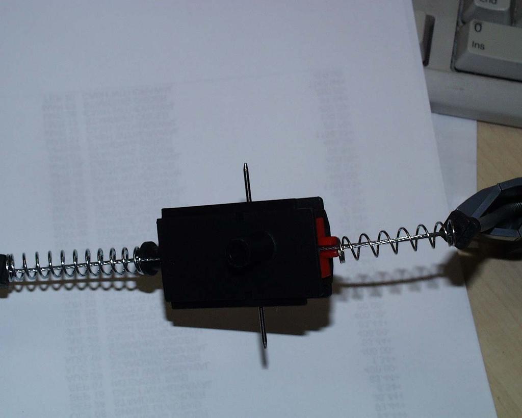
11 K. Hold the slider and yoke so that when looking at the parts they are in the same orientation as the sketch above. Pull the yoke away from the slider until it is tight against the pinion. Hold in this position with the left hand. L. Pick up rack and orientate with respect to yoke and slider as the sketch above. Locate the bottom end of the Timing Pin through the hole in the side of the rack. Slide rack up the timing pin until it gets to the slider. Pull the Timing Pin down until the rack can move across the side of the slider and all the holes line up. Push the timing pin back through the holes. All the pieces of the switching mechanism are now held together by the Pin but the yoke should be able to move in and out of the slider.

12 All the pieces of the switching mechanism are now held together by the Pin but the yoke should be able to move in and out of the slider.
13 M. Offer up the switch mechanism to the lower handle with the shaft of the rack positioned into the left-hand side hole of the main clamshell body. The trick is to slightly lift the main clamshell whilst locating the switch mechanism into the handle. Push the Timing Pin down through the hole in the lower handle clamshell. The switch mechanism is now positioned correctly. N. Working away from the switch mechanism towards the blades locate the spring against the first rib (ensure spring is correctly fitted on yoke boss) and the conduit fitting on the end of the Bowden cable is against the second rib. Finally, locate front handle into rear handle. O. Working away from the switch mechanism towards the cable locate the spring against the first rib (ensure spring is correctly fitted on slider boss) and the conduit fitting on the end of the Bowden cable against the other side. Dress the Bowden cable around the screw bosses and locate the two triggers into the pivot holes at either side of the lower rear handle. P. Place the upper rear handle over your right arm and hold the triggers in place with the fingers of the right hand. Maneuver the upper handle into the correct orientation and position onto the lower handle. Fit the two screws either side of the pivot point to 0.8/1.0Nm and then fit the screw at the cord protector ensuring the cord protector and triggers are correctly located. Q. Fit and tighten all other screws to 0.8/1.0Nm ensuring that the two screws at the very front of the rear handle are the two slightly longer ones. R. Pull Timing Pin from the hole in the lower handle clamshell. Check operation of switch mechanism by operating, with the handle locked into one of the two operating positions, the front and one of the rear triggers. Two clicks should be heard on operating the triggers and releasing them.

14 Pull timing pin ( ) out through lower clamshell Replacing sub assembly Blade and Gear.

15 1. Carry out steps A to D. Spirol pins 2. At this point the Spirol Pins will be still through the blade support into the lower handle or may have pulled out of the lower clamshell, being held firmly by the cover clamshell. With a pair of pliers remove the pins. 3. Take hold of the blade with one hand and rotate the blade tip upward to approximately a 45-degree angle and then lift the blade and gear from the clamshell. 4. Ensure correct location of motor and intershaft. 5. Fit sintered bearings to the gear shaft and present the blade gear assembly to the clamshell with the tip held up at 45 degrees. 6. Position the gear and shaft into the clamshell ensuring correct tooth alignment and then lower the tip of the blade down until the blade support rests in the clamshell. 7. Align the two holes in the blade support with the corresponding holes in the clamshell and push the spirol pins through and into the clamshell until approx. 8mm of spirol
16 pin is left above the top of the blade support. Note light encouragement with a soft hammer may be required to locate the spirol pins. 8. Grease the gears as required. 9. Carry out steps E to Q.
17 New Parts GT370 HEDGE TRIMMER Part Number Part Description SHEATH TIMING PIN BLADE & GEAR SA LEAD SA ACTUATOR LATCH ACTUATOR TRIGGER TRIGGER ACTUATOR BOLT BOLT NUT M4 SPIROL PIN WARNING LABEL ROLLER CASTING SA RATING PLATE WASHER LOCK PINION RACK YOKE SLIDER SWITCH SWITCH CABLE SA Please DO NOT order any parts until a Service Change Note is published. 18 February 2004 P1ant: LCE Page 1 of 2
18 Part Number Part Description CABLE SA CORDSET CORDSET CORDSET THRUST PLATE SPRING WASHER MOTOR SA HANDLE SA SPRING SPRING LABEL LABEL LABEL HANDLE SA INTERGEAR SA CLAMSHELL SET BEARING Any queries please contact the European Service Support Group Martin Cook : Steve Hurt : Martin Chadwick : Sean Holden : Please DO NOT order any parts until a Service Change Note is published. 18 February 2004 P1ant: LCE Page 2 of 2


19 Wire Routing 230V European Version. Completed handle prior to fitting top cover. See following pages detailing wire positions. Motor seated in lower Clamshell. Switches positioned onto pins with White Plunger uppermost. Note :- It is extremely important that the wires are positioned behind the air vent as shown. Wires must not be seen protruding from this vent.


20 Motor leadwires from Terminal Block located into Wire Traps in lower Handle. Note :- Excess wire looped into Handle at pivot hole in main Clamshell. Leadwires positioned through pivot hole when Cover half of Clamshell is fitted.

21 Leadwires located into lower Handle behind rib away from Trigger. The photographs and text above are to be used in conjunction with the Product Assembly and Test drawing to aid assembly of the unit.
GT371 HEDGETRIMMER TYPE
 GT371 HEDGETRIMMER TYPE 1 Introduction Exploded Drawing Bill Of Material Repair Instructions E13791 GT371-----A New Parts Wiring Diagram Main Menu 3 18 02-04 SEAN HOLDEN GT371 MANUFACTURING PLANT USTI
PRODUCT MANUAL - M096
 PRODUCT MANUAL - M096 MODEL 270 ELECTRIC CAN OPENER 1 I. LABELS L087--CAUTION 2 II. SPECIFICATIONS MODEL NO. 270 POWER 115 VOLT, 1.5 AMP, 50-60HZ REQUIREMENTS 230 VOLT, 0.8 AMP, 50-60 HZ NORMAL SPEED 200-250
Urea/Adblue Hose Reel
 www.scintex.com.au sales@scintex.com.au Model: SHR3408 Urea/Adblue Hose Reel Product Manual Specifications Spring driven drum: for automatic rewind. Locking ratchet: to maintain the desired length of hose
Roller Bar End Cap (w/round Drive Shaft) Replacement Instructions for Vista and Motorized Awnings * Helpers needed *
 Replacement Instructions for Vista and Motorized Awnings * Helpers needed *") RETRACTABLE AWNINGS For Technical Support visit us at www.sunsetter.com/ownerscorner or Call Toll Free 800-670-7071 Fax 877-224-4944 Roller Bar End Cap (w/round Drive Shaft) Replacement Instructions for
RETRACTABLE AWNINGS For Technical Support visit us at www.sunsetter.com/ownerscorner or Call Toll Free 800-670-7071 Fax 877-224-4944 Roller Bar End Cap (w/round Drive Shaft) Replacement Instructions for
SERVICE SHEET 34" WALK-BEHIND POWER TROWEL MODEL FT34 (THIS SERVICE SHEET APPLIES TO THE TROWELS WITH SERIAL NUMBER AND AFTER) WARNING
 WARNING") 34" WALK-BEHIND POWER TROWEL (THIS APPLIES TO THE TROWELS WITH SERIAL NUMBER 0837 AND AFTER) WARNING To reduce the risk of injury, all operators and maintenance personnel must read and understand these
34" WALK-BEHIND POWER TROWEL (THIS APPLIES TO THE TROWELS WITH SERIAL NUMBER 0837 AND AFTER) WARNING To reduce the risk of injury, all operators and maintenance personnel must read and understand these
INSTALLATION INSTRUCTIONS
 INSTALLATION INSTRUCTIONS KR54, KR1654, & KR4954 Keyed Removable Mullion NOT FOR USE ON ELECTRIC OR FIRE RATED MULLIONS. This kit includes the following parts: (Not to scale) WARNING Remove key, reinstall,
* * 4023 KR. Step 1 Prepare the Keyed Removable Unit. Not for use on electric or fire rated removable mullions
 condition. *64009-00* 64009-00 Keyed Removable Mullions 403 KR Installation Instructions Not for use on electric or fire rated removable mullions This kit includes the following parts: (Not to scale) 5/6
PR-429BF-600M. Bell 429 Blade Fold Kit Operations Manual
 Table of Contents Table of Contents... 1 Record of Revisions... 2 References... 3 Introduction... 4 Contact Information... 4 Prerequisites... 5 First Time Use... 6 Blade Clamp Placement... 6 Blade Clamp
HANDLES AND CONTROL CABLES
 Worm Drive Transmission........................ 1 Single Speed Spur/Bevel Gear Transmission............. Single Speed Bevel Gear Transmission................ Three Speed Transmission.......................
JARVIS. Model 70 Airsnip Air Powered Scissors
 Air Powered Scissors EQUIPMENT SELECTION... Ordering No. Airsnip Model 70... 4019009 Air Filter/Regulator/Lubricator.. 3022003 Balancer... 1350084 Power--Pak (250 PSI)... 4026016 TABLE OF CONTENTS... Page
* * KR54-F, KR9854 & KR9954 Installation Instructions. Read All Warnings Before Starting Installation! Index:
 *941061-00* 941061-00 Keyed Removable Mullion KR54-F, KR9854 & KR9954 Installation Instructions CLASSIFIED CLASSIFIED C Read All Warnings Before Starting Installation! Index: General Information ----------------
Thanks for shopping with Improvements! 10 Solar Lighted Gazebo Item #531753
 Thanks for shopping with Improvements! 10 Solar Lighted Gazebo Item #531753 Parts List: A. Frame Qty: 1 B. Canopy Qty: 1 C. Stake Qty: 8 D. Brace Qty: 4 E. Cap Qty: 1 F. Battery Qty: 2 G. Rope Qty: 4 H.
Assembling & Fitting Instruction August 2015
 Assembling & Fitting Instruction August 2015 Wave Curtain Heading System Silent Gliss 6010, 6020, 6100, 6103, 6290, 6380, 6465 Silent Gliss 3840, 6120 Silent Gliss 5090, 5200, 5400 Silent Gliss 5100, 5600
FREEDOM BUTTON KIT INSTALLATION GUIDE STEP 1
 FREEDOM BUTTON KIT INSTALLATION GUIDE Installation of the Freedom Button kit is very simple and similar to the installation of a standard rear takedown pin and bolt catch latch. Before installing your
Tank. Part B, Section 1. This section covers the following unit configurations. Pump Piston Pump (E or G)
") Part B, ection Model Voltage This section covers the following unit configurations. 3400V All Pump Piston Pump (E or G) Manifold Control 4-Port (A) Vista tandard (V) Vista Pattern (PC) Vista Temperature
Part B, ection Model Voltage This section covers the following unit configurations. 3400V All Pump Piston Pump (E or G) Manifold Control 4-Port (A) Vista tandard (V) Vista Pattern (PC) Vista Temperature
Assembly TOOLS REQUIRED: 17mm and 14mm or equivalent wrenches.
 Instructions for 3 Trimmer Rack, 3TR* *Patents Pending Assembly TOOLS REQUIRED: 17mm and mm or equivalent wrenches. 15 26 26 16 15 16 Attach the lower mounting brackets to the Trimmer Rack poles as shown
Product instruction manual Ream Cutting Systems RE3943, RE3946, RE3947, RE3971, RE3952E
 Product instruction manual Ream Cutting Systems RE3943, RE3946, RE3947, RE3971, RE3952E The Trimfast Ream Cutters are reliable, high performance cutters that will give you the results you need quickly
AND LOAD CANOPY RACK SPECIFICATIONS
 8MAY15 INSTRUCTIONS for the LOCK AND LOAD CANOPY RACK SPECIFICATIONS and SAFE LOADING REQUIREMENTS The Lock and Load ladder carrier for Truck Caps is a rack designed to mount to the top of a pickup truck
33100 LH - Batwing Awning RH - Batwing Awning
 33100 LH - Batwing Awning 33200 RH - Batwing Awning 1. Check Part No./Kit is correct 3. Fit roof rack accessory 2. Read through instruction before installing 4. Check and recheck all fasteners are secure
PARTS BOOK CATALOG SIDE HD FLAIL HEADS TRACTOR MID-MOUNT
 PARTS BOOK CATALOG SIDE HD FLAIL HEADS TRACTOR MID-MOUNT DIAMOND MOWERS, Inc. 350 E 60 th St. North Sioux Falls, SD 57104 FOR WARRANTY CALL DIAMOND MOWERS DIRECT: 888-960-0364 OUR TECHNICIANS WILL DIAGNOSE
STIH) Technical Information Cut-off machine STIHL Cutquik TS 410, 420 Series Guard with defined adjustment range
 Technical Information Cut-off machine STIHL Cutquik TS 410, 420 Series Guard with defined adjustment range") STIH) Technical Information 5.009 Cut-off machine STIHL Cutquik TS 40, 40 Series 48 Contents. Guard with defined adjustment range. Belt guard, screw. Set of instruction labels 4. Summary. Guard with defined
STIH) Technical Information 5.009 Cut-off machine STIHL Cutquik TS 40, 40 Series 48 Contents. Guard with defined adjustment range. Belt guard, screw. Set of instruction labels 4. Summary. Guard with defined
FLEX KEY ASSEMBLY. ..._ o RAFTER ARM TUBE MAIN ARM TUBE CAP NUT CLAW HINGE
 ZIP DEE Inc. 96 Crossen Ave. Elk Grove Village, IL 60007(847)437-0980 (800)338-2378 HEAD CASTING AWNING RAIL FLEX KEY ASSEMBLY..._ o GM1 Installation Instruction GMC Motorhome RAFTER ARM TUBE MAIN ARM
Cassette-folding arm-awning markilux 990
 Cassette-folding arm-awning markilux 990 Mounting instructions 1. Overview 1 Projection profile 2 Folding arm 3 Fabric 4 Console 5 Cassette 6 Covering cap 7 Wall bracket 2. Mounting brackets 2.1 Overview
quick and easy installation guide
 www.directdriveopener.com quick and easy installation guide Back 2 Front. Motor Carriage 2. C-rail. Chain. Limit stops. Slide in part (tensioner) Rail assembly Insert C-rail parts () into the connecting
80070 TOP MOUNT CAMPER SHELL and TRANSIT CONNECT RACK TMCS_3:1
 ASSEMBLY INSTRUCTIONS for : 80070 TOP MOUNT CAMPER SHELL and TRANSIT CONNECT RACK TMCS_3:1 (916) 638-8703 (800) 343-7486 11261 Trade Center Drive Rancho Cordova, CA 95742 www.kargomaster.com Transit ASSEMBLY
DO NOT use Alien Flier Zip Line Products until you have read and fully understand the SAFETY WARNINGS below!
 SAFETY WARNING DO NOT use Alien Flier Zip Line Products until you have read and fully understand the SAFETY WARNINGS below! Assumption of Risk Zip line construction and use can be dangerous. Ensure you
SOFT TOP ROOF TENT INSTRUCTION MANUAL
 SOFT TOP ROOF TENT INSTRUCTION MANUAL CONTENTS SET UP INSTRUCTIONS: 1. INSTALLING YOUR ROOF TOP TENT P2-3 2. SETTING UP YOUR ROOF TOP TENT P4 3. PACKING DOWN YOUR ROOF TOP TENT P5-6 4. TIPS & TRICKS P7
SPIRIT FX, FIESTA AND SIMPLICITY AWNINGS. Printed From
 RV INSTALLATION MANUAL MANUALLY OPERATED PATIO AWNING SPIRIT FX, FIESTA AND SIMPLICITY AWNINGS These instructions apply to all models listed. Details and procedures unique to a specific model are labeled
Advantage Plus TIM-3600 Series Reel
 Read the following precautions and instructions before you begin assembly or using. Failure to comply with these instructions could result in personal injury or property damage. Keep these instructions
NEWMAR SERVICE SCHOOL
 NEWMAR SERVICE SCHOOL TRAINING INFORMATION GUIDELINE FOR FEBRUARY 2013 OUR PRODUCTS: NOVA DUAL PITCH AWNING G-2000/ G-1500 2 P a g e G-2085 G-5000 3 P a g e G-LINKS 4 P a g e NOVA/ G-2000/ G-1500 BASIC
INSTRUCTIONS INSTALLATION UNIVERSAL SERIES PATIO AWNING HARDWARE , , ,
 RECORD THIS INFORMATION FOR FUTURE REFERENCE: Model Number Serial Number Hardware Model Number Hardware Serial Number Date Purchased Retailer / Qualified Installer INSTALLATION INSTRUCTIONS UNIVERSAL SERIES
TITAN Fuel Tanks. INSTALLATION INSTRUCTIONS G e n e r a t i o n V
 TITAN pt. no.: 02 0000 0128 Important: Please read these instructions carefully and completely before starting the installation. TITAN Fuel Tanks INSTALLATION INSTRUCTIONS G e n e r a t i o n V Extended
Contents. Awnings USA - Full Protective Hood Manual Instructions ft 11" - 11ft 6" Awnings
 Awnings USA - Full Protective Hood Manual Instructions Contents Warning We recommend that two or more people are required to lift the awning into place. 4ft 11" - 11ft 6" Awnings 8 x Expansion bolts **
Installation and User s Manual 12 x 10 MOTORIZED AWNING
 12 x 10 MOTORIZED AWNING Installation and User s Manual 12 x 10 MOTORIZED AWNING 088-1763-0 Stop Please read and understand this manual before any assembly or use of this product. Before beginning assembly
PARTS LIST COLT COLT HEPA
 PARTS LIST COLT 800-1250 - 1450 COLT HEPA - 1250-1450 MOTOR / LID ITEM PART NO. PART DESCRIPTION QTY. 101 0891201 TOP COVER 1 102 0294341 TOP MOTOR SEAL 1 103 0299861 STRAIN RELIEF CORD CLAMP 1 104 0891131
SERVICE MANUAL- M126
 SERVICE MANUAL- MANUAL CAN OPENER- MODEL # 2 1 Model #2 Can Opener Assembly Procedure The Model #2 can opener will be assembled according to the following procedure. I. Model #2 Handle and Arbor Assembly
4.2 Assembly Instructions
 4.2 Assembly Instructions 4.2.1 Assembly of Reserve Canopy. Assembly of Reserve Canopy using Rapide Links. After inspecting the Parachute and the Wings Harness/Container System, hang or lay the parachute
M129 SERVICE MANUAL- M129 MODEL #G-2 MANUAL CAN OPENER
 SERVICE MANUAL- M129 MODEL #G-2 MANUAL CAN OPENER Model #G-2 Can Opener Assembly Procedure The Model #G-2 can opener will be assembled according to the following procedure. I. Model #G-2 Handle and Arbor
Parts Lists. Parts List Index. Using the Parts Lists
 Parts Lists Parts List Index PL 1.1 Covers (1 of 2).............. 7-2 PL 9.1 Frame and Size Sensor....... 7-22 PL 1.2 Covers (2 of 2).............. 7-4 PL 10.1 Electrical................. 7-24 PL 2.1 Tray
SPIRAL SLICER Instruction Manual Model #5280 & 5280M. Part No Revised Feb. 2010
 SPIRAL SLICER Instruction Manual Model #5280 & 5280M Part No. 82876 Revised Feb. 2010 SAFETY PRECAUTIONS INSTALLATION INSTRUCTIONS Inspection of Shipment: 5280 & 5280M SPIRAL SLICER Unpack all cartons
BowDown. MiniMuM Crossbar spread 24 (61CM) Steel Hook (2X) Buckle Strap (2X) Plastic Tube (2X) Plain Strap (2X) SHORT BLACK T-BOLT (2x) BOWDOWN (2x)
 Steel Hook (2X) Buckle Strap (2X) Plastic Tube (2X) Plain Strap (2X) SHORT BLACK T-BOLT (2x) BOWDOWN (2x)") BowDown MiniMuM Crossbar spread 24 (61CM) Heavy Duty strap (2x) SHORT BLACK T-BOLT (2x) BOWDOWN (2x) Bow Stern Tie Down Buckle Strap (2X) Plastic Tube (2X) Plain Strap (2X) Steel Hook (2X) IMPORTANT WARNING
BowDown MiniMuM Crossbar spread 24 (61CM) Heavy Duty strap (2x) SHORT BLACK T-BOLT (2x) BOWDOWN (2x) Bow Stern Tie Down Buckle Strap (2X) Plastic Tube (2X) Plain Strap (2X) Steel Hook (2X) IMPORTANT WARNING
Primrose Awnings - Full Cassette Manual & Electric Instructions
 Primrose Awnings - Full Cassette Manual & Electric Instructions Contents Warning 2.0m - 3.5m Awnings 8 x Expansion bolts ** 2 x brackets 1 x Awning 1 x Winder 4.0m - 5.0m Awnings 12 x Expansion bolts **
BERYL Service Guide. Travel Adjust OTT Change
 BERYL Service Guide Travel Adjust OTT Change SERVICE OVERVIEW This manual will guide you step by step performing a travel adjust and OTT setting change to your Beryl suspension fork. Please follow each
Thomas Scientific Swedesboro, NJ U.S.A.
 Thomas Scientific Swedesboro, NJ 08085-0099 U.S.A. Wiley Laboratory Mill, Model 4 3375-E10 (115 V, 50/60 HZ) USE AND CARE OF CATALOG NUMBER: 3375-E10 Wiley Laboratory Mill, Model 4 (115 V, 50/60 HZ) UNPACKING
4812 HEAVY BAG STAND OWNER S MANUAL
 48 HEAVY BAG STAND OWNER S MANUAL Note:Warning Labels Everlast Worldwide, 00 Hwy DD, Moberly, MO 65270 Customer Service 800.821.7930 14 C4 48 HEAVY BAG STAND OWNER S MANUAL CONGRATULATIONS! YOU HAVE JUST
MYRIAD Banner Stand is a trademark of Skyline Exhibits. Patent Pending PN32294-B. MYRIAD Banner Stand
 is a trademark of Skyline Exhibits Patent Pending 1.1 1. Banner Stand Setup 1.1 Remove banner stand from standard case or Arrive Portable Display & Workstation and assemble pole. 1.2 Insert pole into base
MOTORIZED OR MANUAL LATERAL ARM BOX AWNING. Product Overview... 1 Component Checklist... 2
 INSTALLATION MANUAL FREEDOM AWNING RV MOTORIZED OR MANUAL LATERAL ARM BOX AWNING TABLE OF CONTENTS Product Overview... 1 Component Checklist... 2 Installation... 3 Attaching the Mounting Plates... 3 Mounting
FIESTA & FIESTA HD PATIO AWNINGS
 INSTALLATION MANUAL FIESTA & FIESTA HD PATIO AWNINGS MANUALLY OPERATED PATIO AWNING RV Read this manual before installing or using this product. Failure to follow the instructions and safety precautions
Exploded views meat slicer: 800S. DEKO Holland bv B Arnhem The Netherlands
 Exploded views meat slicer: 800S DEKO Holland bv. 6827 B Arnhem The Netherlands DEKO Holland bv. Recommended spare parts list Part no. Description 260-07/ 260-08/ 260-5 Switch 230 Volt / Switch 400 Volt
AFC-50 Automatic French Fry Cutter Instruction Manual
 AFC-50 Automatic French Fry Cutter Instruction Manual Fry Factory Inc. 67 Watts Ave, Charlottetown, PEI, C1E 2B7, Canada Phone: 902-368-2900 Fax: 902-368-8645 Email: info@fryfactoryinc.com Website: www.fryfactoryinc.com
Door Bushing Replacement & Latch Adjustment Monaco Group Coaches
 Door Bushing Replacement & Latch Adjustment Monaco Group Coaches Contents Door Latch Adjustment & Repair... 1 Symptoms:... 1 Replacing the bushing VS. Adjusting the latch rods.... 1 How the bushing works....
PARTS LIST eforce Burnisher
 PARTS LIST eforce Burnisher HEAD ASSEMBLY ITEM PART NO. DESCRIPTION QTY 101 6496721 MOTOR 36 VOLT, 2100 RPM, 3.6HP [see pages 16,17] 1 102 9121410 5/16 EXTERNAL STAR LOCK WASHER PACK OF 10 2 103 6492051
Product Overview... 1 Specifications Canopy Replacement... 2 Removing the Fabric and Roller Tube... 2 Installing the Fabric and Roller Tube...
 SERVICE MANUAL SLIDEOUT COVER RV TABLE OF CONTENTS Product Overview... 1 Specifications... 1 Canopy Replacement... 2 Removing the Fabric and Roller Tube... 2 Installing the Fabric and Roller Tube... 2
INSTRUCTION MANUAL ALEKO RETRACTABLE AWNING
 INSTRUCTION MANUAL for ALEKO RETRACTABLE AWNING www.alekoproducts.com FAILURE TO FOLLOW THESE INSTRUCTIONS MAY RESULT IN PERSONAL INJURY! 1 Important Safety Precautions WARNING NOTE: FOR PERSONAL SAFETY,
Shut off combine and remove key before installing the hopper extension. Make sure the combine is on a level surface. Engage parking brake.
 ASSEMBLY INSTRUCTIONS CASE IH 5088, 6088/7088, 7010/8010 & 7120/8120/9120 Series NEW HOLLAND CR STD Series Combines (Large) big top 26301(service only), 29976 (service only), 53408, 53543 & 54274 The Crary
FREEDOM WM AWNING. Product Overview... 1 Component Checklist... 2
 INSTALLATION MANUAL FREEDOM WM AWNING MOTORIZED OR MANUAL LATERAL ARM BOX AWNING RV Read this manual before installing or using this product. Failure to follow the instructions and safety precautions in
RETRACTABLE AWNING w/ OPTIONAL HOOD ASSEMBLY INSTRUCTIONS
 Contact us @ (800)851-0865 RETRACTABLE AWNING w/ OPTIONAL HOOD ASSEMBLY INSTRUCTIONS Congratulations on your purchase of a new retractable awning. With proper installation this awning will provide years
User manual for shredder KIT
 2014 User manual for shredder KIT Thymark FilaMaker 1.1.2014 User manual shredder KIT 1) what is in your kit. 2) which tool do you need 3) building your shredder step by step 4) Warnings and safety 5)
4A1-114/114KR & 4A1-2 MANUAL TENSIONERS
 M L. C O O N AL TO 4A1-114/114KR & 4A1-2 W W W.T R AD IT IO MANUAL TENSIONERS READ THESE INSTRUCTIONS CAREFULLY. FAILURE TO FOLLOW THESE INSTRUCTIONS CAN RESULT IN SEVERE PERSONAL INJURY. GENERAL SAFETY
MODEL # 1 MANUAL CAN OPENER
 REV.B SERVICE MANUAL MODEL # 1 MANUAL CAN OPENER Model #1 Can Opener Assembly Procedure The Model #1 can opener will be assembled according to the following procedure. I. Model #1 Handle and Arbor Assembly
PLATINUM MODEL WITH AUTO-RETRACT AND REMOTE CONTROL. Owner s Manual
 PLATINUM MODEL WITH AUTO-RETRACT AND REMOTE CONTROL Owner s Manual THIS MANUAL CONTAINS INSTRUCTIONS FOR UPGRADING BOTH THE GOLD MODEL ONE-TOUCH AND THE ONE-TOUCH MODEL WITH THE KEY SWITCH TO THE PLATINUM
Congratulations! On the purchase of your Black & Decker saw.
 KS890GT Congratulations! On the purchase of your Black & Decker saw. To ensure the best results from your saw please read these safety and usage instructions carefully. If you have any questions or queries
FREEDOM WM AWNING MOTORIZED OR MANUAL LATERAL ARM BOX AWNING. Product Overview... 1 Component Checklist... 1
 INSTALLATION MANUAL FREEDOM WM AWNING RV MOTORIZED OR MANUAL LATERAL ARM BOX AWNING TABLE OF CONTENTS Product Overview... 1 Component Checklist... 1 Installation... 3 Attaching the Mounting Plates... 3
NS 200 Series Hose Reel January 2011
 Instructions Parts List Service Manual NS 200 Series Hose Reel January 2011 Suitable for dispensing, transfer and evacuation of lubricants, fuels, air & other automotive & industrial products. To be used
Tidland Series 'C' Knifeholder MAINTENANCE MANUAL Crush Cartridge Class I, II, III Crush Slitting
 Tidland Series 'C' Knifeholder MAINTENANCE MANUAL Crush Cartridge Class I, II, III Crush Slitting Please read and understand all the instructions before you start to maintain the Tidland Series 'C' Knifeholder.
USER S OPERATING AND INSTRUCTION MANUAL
 Grand Rapids, Michigan, U.S.A. 49504-5298 USER S OPERATING AND INSTRUCTION MANUAL MODEL 709 MINI SUPREME BREAD SLICER 0709S20000-CV INDEX SAFETY INSTRUCTIONS... 0709S20025 DEFINITIONS... GEN 931118 INSTALLATION
PARTS BOOK FLAIL HEADS 90 REAR 3PT HITCH MOUNT
 PARTS BOOK FLAIL HEADS 90 REAR 3PT HITCH MOUNT 5.0.8 DIAMOND MOWERS, LLC 350 E 60 th St. North Sioux Falls, SD 5704 FOR WARRANTY CALL DIAMOND MOWERS DIRECT: 888-960-0364 OUR TECHNICIANS WILL DIAGNOSE YOUR
Phantom Retractor System Overview
 Spine Phantom Retractor System Overview Minimally invasive procedures Dual-directional expandable retractor 30 degree pivoting blades Fiber-optic light source for better visualization Key Design Features
HANDLE AND WHEEL KIT INSTALLATION
 HANDLE AND WHEEL KIT INSTALLATION Select EB and EM Series Generators Honda Power Equipment Your generator is equipped with a wheel kit and folding handle kit for easy transport and convenient storage.
42" SNOW BLADE. Owner's Manual. Model No Safety Assembly Operation Maintenance Parts
 Owner's Manual 42" SNOW BLADE Model No. 486.24443 CAUTION: Before using this product, read this manual and follow all Safety Rules and Operating Instructions. Safety Assembly Operation Maintenance Parts
Tuf-Lite and Tuf-Lite II Fans 6000M Series Hub
 Tuf-Lite and Tuf-Lite II Fans 6000M Series Hub INSTALLATION MANUAL Adjustable Pitch Fan Assembly 32.8 or 10 Meter Diameter Hudson Tuf-Lite and Tuf-Lite II fan blades Hudson Tuf-Lite (black) fan blades
Parts Catalog T7/T71/T73 M40000/M40001/M40003
 T7/T71/T73 M40000/M40001/M40003 REPAIR PARTS CATALOG NO. For machines starting with Serial No. T10001 ISSUED August 2010 ORDERS Please use Part Numbers when ordering and include the machine Serial Number
Primrose Awnings Full Cassette Manual & Electric Instructions
 Primrose Awnings Full Cassette Manual & Electric Instructions Contents for Full Cassette Awning 1 x Remote control receiver box 2 x Remote hand-held zappers 1 x 5 metre cable 1 x Template sticker **The
VEPR Round Drum Disassembly and Assembly
 VEPR 12 25 Round Drum Disassembly and Assembly Required Tools ¼ Allen Wrench Flat Head Screwdriver Drum Parts List Drum Body Carousel Center Bolt Dummy Rounds Carousel Lock Spring Clear Drum Cover Step
Motorized retractable awning
 Motorized retractable awning Model 95295 Set up And Operating Instructions Diagrams within this manual may not be drawn proportionally. Due to continuing improvements, actual product may differ slightly
Notes, Parts List & Drawings
 Biomass Chopper/Cutter Notes, Parts List & Drawings Page 1 of 16 The Easy BioChop biomass chopper/cutter was designed to cut both wet and dry biomass and to accomplish a number of goals. The objectives
Insruction manual Dukki
 Insruction manual Dukki Introduction Pg. 1 Product description Pg. 2 3 Assembly and disassembly Pg. 4 Installation and adjustment Pg. 5 12 Maintenance Pg. 13 Parts Pg. 14-17 INDEX 1. Introduction 1 2.
TRAVEL'R ARMS AND CANOPY
 RV INSTALLATION MANUAL TRAVEL'R ARMS AND CANOPY THIS MANUAL PROVIDES INSTRUCTIONS FOR ORIGINAL EQUIPMENT MANUFACTURER (OEM), AFTERMARKET INSTALLATIONS AND ARM UPGRADES FOR CURRENT CAREFREE AND A&E AWNINGS
Installation Guide: Round Trampoline
 Trampolines & trampoline parts designed to survive in the harsh Oz climate. www.oztrampolines.com.au Installation Guide: Round Trampoline Safety Tips Here at Oz Trampolines we are passionate about your
BUILT-IN OVEN SAFETY
 UILT-IN OVN SFTY Your safety and the safety of others are very important. We have provided many important safety messages in this manual and on your appliance. lways read and obey all safety messages.
MOTORIZED FOLDING CAMPER WINCH
 OWNER'S MANUAL MOTORIZED FOLDING CAMPER WINCH With 1200lb Lift Capacity The 12 Volt Motorized Folding Camper Winch is used to raise and lower folding campers with the touch of the switch, eliminating hand
INSTALLATION INSTRUCTIONS AND OWNER'S MANUAL AWNINGS. For trailers & motor homes with straight sides TOOLS REQUIRED
 AWNINGS INSTALLATION INSTRUCTIONS AND OWNER'S MANUAL For trailers & motor homes with straight sides TOOLS REQUIRED 1/4" electric drill Ratchet handle kit 3/8" & 7/16" socket No. 1 and No. 2 screwdriver
ALEKO Victoria Series Retractable Awning Instructions for Installation and Operation
 www.alekoproducts.com ALEKO Victoria Series Retractable Awning Instructions for Installation and Operation PLEASE DO NOT RETURN THIS PRODUCT TO THE STORE! The owner s manual includes assembly and operating
Thermostatic Griddle Field Service Kit Instructions
 Thermostatic Griddle Field Service Kit Instructions The following document provides instructions on how to install a Garland Thermostatic Griddle Field Kit and is applicable to each 2 section of a Garland
READ ME! IMPORTANT WARNING! ENG. Quick Release Tent Mount Kit
 Quick Release Tent Mount Kit ENG TBMK008 READ ME! Thank you for purchasing a Front Runner Quick Release Tent Mount Kit. Before you start, take a moment to familiarize yourself with the Fitting Instructions
Alien Flier Zip Line Products Installation/Owner s Manual
 Alien Flier Zip Line Products Installation/Owner s Manual 1 Table of Contents SAFETY PLEASE READ CAREFULLY... 4 Constructing your Zip Line Xtreme Models... 6 Installing your Alien Flier Trolley on an Existing
P3000 UNIVERSAL Clamp-On
 IHI INSTRUCTION MANUAL Required Tools P3000 UNIVERSAL Clamp-On Wrench Allen Key P3001 65 ENDCAPS P3011 65 BLACK P300 7 ENDCAPS P301 7 WHITE P3003 ENDCAPS P3013 SILVER PART# DESCRIPTION ENDCAPS SIDE SUPPORTS
PARTS LIST CHARGER 2022 ABLT
 PARTS LIST CHARGER 2022 ABLT HEAD ASSEMBLY ITEM PART NO. DESCRIPTION QTY 101 5990731 SPRING CLIP PAD HOLDER SET INCLUDES: 1 101A 9120205 #8 X 1/2 PAN HEAD PHILLIPS SHEET METAL SCREW PACK OF 3 3 102 9121490
CHANGING YOUR LANDSCAPE SINCE 1945 OWNER S MANUAL. Tow Hitch Replacement Kit For Rough Cut Trailcutters. Starting Serial # L
 CHANGING YOUR LANDSCAPE SINCE 1945 OWNER S MANUAL Tow Hitch Replacement Kit For Rough Cut Trailcutters 21100 Starting Serial # L118-023001 Tools Required: Wrench/Socket Qty. Size (1) 1-1/8 (1) 1-1/16 (2)
Optional Controls (Depends which set was purchased) Set A (Remote control kit)
 Set A (Remote control kit)") Primrose Awnings - Full Cassette Manual & Electric Instructions Contents Warning 1.5m - 3.5m Awnings 8 x Expansion bolts ** 2 x brackets 1 x Awning 1 x Winder 4.0m - 5.0m Awnings 12 x Expansion bolts **
Primrose Awnings - Full Cassette Manual & Electric Instructions Contents Warning 1.5m - 3.5m Awnings 8 x Expansion bolts ** 2 x brackets 1 x Awning 1 x Winder 4.0m - 5.0m Awnings 12 x Expansion bolts **
Alien Flier Zip Line Products Installation/Owner s Manual
 Alien Flier Zip Line Products Installation/Owner s Manual 1 Table of Contents SAFETY PLEASE READ CAREFULLY... 4 Explorer Zip Line EZ Up Cable Kit Installation... 5 Xtreme Zip Line EZ Up Cable Kit Installation...
TASK FORCE TIPS * *
 1" TWISTER AND BUBBLECUP SERIES -SERVICE PROCEDURE- TIP ONLY BUBBLECUP W/GRIP TWISTER W/GRIP TASK FORCE TIPS * 800.348.2686 * http://www.tft.com TASK FORCE TIPS, INC. www.tft.com 1.0 SERIES Twister and
BILLY GOAT KV HOSE KIT (P/N ) PURPOSE: To allow for vacuuming in hard to reach places.
 PURPOSE: To allow for vacuuming in hard to reach places.") BILLY GOAT KV HOSE KIT (P/N 891125) PURPOSE: To allow for vacuuming in hard to reach places. Part No 891061-1 - Form No F052209A INSTALLATION: Step 1. Attach nozzle wear guards. 1. Disconnect spark plug
BILLY GOAT KV HOSE KIT (P/N 891125) PURPOSE: To allow for vacuuming in hard to reach places. Part No 891061-1 - Form No F052209A INSTALLATION: Step 1. Attach nozzle wear guards. 1. Disconnect spark plug
CLIPPERMAN INSTRUCTION MANUAL
 CLIPPERMAN INSTRUCTION MANUAL THE KNOWLEDGE AND POWER TO OUTPERFORM Welcome to Clipperman and thank you for purchasing your new product from our range, and placing your trust in us. GUARANTEE & WARRANTY
WARRENTY Void IF BROKEN 48,0 COMBINATIONS FIXED CYLINDER A A A A M = MASTER KEY SYSTEM: SUPPLIED TO ORDER ONLY
 Coin Lock 264/265/268 COIN RETURN TRAY 33,2 113,5 0,0 18,0 28,8 FOR 264,265 & 269 19,0 FOR 268 26,2 16,5 13,5 34,0 6,0 WARRENTY Void IF BROKEN 48,0 32,5 15,4 18,0 Ø 6,5 9,8 3,0 Ø22,0 1,5 5,6 (RH) REMOVE
RUPHIS Blade Clamp. Instruction Manual
 RUPHIS Blade Clamp P/N 1006800 NSN 1615-01-562-8156 Instruction Manual AH-64D UH-60A/L UH-60M S-70i S-92 REVISION AUTHORIZATION / RECORD These instructions are primarily for inspection of the RUPHIS Blade
Vanagon Ladder Kit Assembly & Installation Instructions
 Rocky Mountain Westy Vanagon Ladder Kit Assembly & Installation Instructions Introduction Thank you for purchasing the Rocky Mountain Westy Vanagon Ladder Kit. We pride ourselves in the products we develop
User Guide. Tripod. flowtech 75 Tripod. Part No. V
 User Guide Tripod flowtech 75 Tripod Part No. V4150-0001 EN www.vinten.com TM Copyright 2017 All rights reserved. Original Instructions: English All rights reserved throughout the world. No part of this
TIN KNOCKER TK NO. 30 CLEAT BENDER INSTRUCTIONS & PARTS DIAGRAM. TK No. 30 CLEAT BENDER
 1 TIN KNOCKER TK NO. 30 CLEAT BENDER INSTRUCTIONS & PARTS DIAGRAM TK No. 30 CLEAT BENDER Sheet Metal Equipment Sales Inc. Dean P. O'Connell, President Green Bay, Wisconsin Phone - (920)-662-9966 Fax -
Congratulations! On the purchase of your Black & Decker saw.
 KS890E Congratulations! On the purchase of your Black & Decker saw. To ensure the best results from your saw please read these safety and usage instructions carefully. If you have any questions or queries