PR-429BF-600M. Bell 429 Blade Fold Kit Operations Manual
|
|
|
- Bryan Chapman
- 6 years ago
- Views:
Transcription
1
2 Table of Contents Table of Contents... 1 Record of Revisions... 2 References... 3 Introduction... 4 Contact Information... 4 Prerequisites... 5 First Time Use... 6 Blade Clamp Placement... 6 Blade Clamp Adjustment... 7 Blade Fold Support Assembly... 8 Main Rotor Blade Folding Procedure... 9 Main Rotor Blade Unfolding Procedure Page 1
3 Record of Revisions Page Revision Date Page Revision Date 1 N/C 05/02/ N/C 05/02/ N/C 05/02/ N/C 05/02/ N/C 05/02/ N/C 05/02/ N/C 05/02/ N/C 05/02/ N/C 05/02/ N/C 05/02/ N/C 05/02/ N/C 05/02/ N/C 05/02/ N/C 05/02/ N/C 05/02/ N/C 05/02/ N/C 05/02/ N/C 05/02/ N/C 05/02/ N/C 05/02/ N/C 05/02/ N/C 05/02/2016 Page 2
4 References BF-100, Blade Fold Provisions Installation Drawing 2. PR-429BF-900M, Blade Fold Provisions Installation Instructions BF-600, Blade Fold Kit Support Installation Drawing and Bill of Materials 4. BHT-429-II-37, Expandable Blade Bolt Kit Installation Instruction Page 3
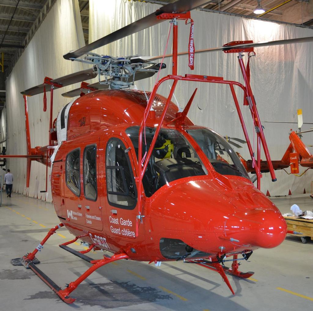
5 Introduction The Blade Fold Kit for the Bell 429 allows the main rotor blades to be folded in a two-blade forward and two-blade aft configuration. The kit consists of a set of permanently installed provisions and a set of supports and clamps that are used to hold the blades when folded. The kit requires that Bell Helicopter part number , Expandable Blade Bolt Kit, be installed prior to use. Refer to Bell Helicopter Installation Instruction BHT-429-II-37. Prior to using the kit for the first time, thoroughly read this manual and have a complete understanding of what is required. If you have any questions, please contact us using the information below. In addition, follow the instructions for First Time Use to mark the blade clamps and set the clamping pressure properly. Two people are required to perform the operation. It takes approximately 15 minutes to fold or unfold the blades. Contact Information The latest version of this manual can be found on the Paravion Technology, Inc. web site at Any questions concerning the use of this kit should be directed to the following. Customer Service Paravion Technology, Inc Airway Avenue Fort Collins, CO USA Phone: +1 (970) FAX: +1 (970) paravion@paravion.com Web Site: Page 4
6 Prerequisites Prior to using this kit, the following items must already be installed on the helicopter. Part Number Description Quantity Vendor Expandable Blade Bolt Kit 1 Bell Helicopter Textron 429BF Blade Fold Provisions Kit 1 Paravion Technology, Inc. Page 5
7 First Time Use When using the kit for the first time, follow the procedures below to mark the installation location for each blade clamp and set its respective clamping pressure. Blade Clamp Placement Beginning with the blade marked by a red triangle, place the center of a Blade Clamp at the following location. Red Triangle Blade Orange Square Blue Diamond Green Circle Distance from Blade Tip to Clamp Center 67.0 inches (1,702 mm) 91.0 inches (2,311 mm) 71.5 inches (1,816 mm) 97.5 inches (2477 mm) After the Blade Clamp is installed on the blade, mark the Blade Clamp location by placing a white chevron decal on both sides of the clamp. The decals can be applied to either the top or bottom of the blade. In addition, mark the Blade Clamp with a red triangle decal. The blade may also be marked with a red triangle at this location if it is difficult to see the red triangle at the root of the blade. If desired, the white chevrons and red triangle may be painted on the blade. Page 6
8 Blade Clamp Adjustment Now that the Blade Clamp has been installed and the blade marked, the clamping pressure needs to be set. Open the Blade Clamp by releasing the lock and raising the handle. Using a spring scale or similar device, pull the handle closed noting the maximum force displayed on the scale. Using a hex key, tighten or loosen the screw on the bottom of the Blade Clamp so that a maximum force of between 18 lbs. (8.16 kg) and 20 lbs. (9.07 kg) is achieved. Repeat the Blade Clamp Placement and Blade Clamp Adjustment procedures above for the remaining three blades; orange square, blue diamond, and green circle. Page 7

9 Blade Fold Support Assembly Attach the Right Forward Blade Support Strut to the Forward Blade Support Assembly using the two bolts, washers, and lock nuts provided. The Right Forward Support Strut should be oriented such that the coupling pin is facing outboard. Page 8

10 Main Rotor Blade Folding Procedure 1. Using an appropriate maintenance stand located at the forward left side of the helicopter, install the designated Blade Clamp on each of the pre-marked blades. The rotor system may be rotated either by the use of the tail rotor or by attaching a blade fold system support strut to a clamp and pulling in the desired direction of rotation. If a support strut is used, while pulling down on the rope to retract the coupling pin, attach the coupling to the ball on the bottom of the Blade Clamp and release the rope tension ensuring the pin has retracted, locking the coupling onto the ball. NOTE: THE BALL COUPLING ON THE UPPER END OF THE SUPPORT STRUT HAS A RELIEF ON ONE SIDE. IT IS IMPORTANT THAT WHEN PULLING ON THE STRUT TO ROTATE THE ROTOR SYSTEM THAT THE RELIEF IS FACING UP TO ALLOW FOR MISALIGNMENT. Page 9

11 To remove the support strut from the Blade Clamp, pull on the rope to disengage the coupling pin allowing the coupling to disconnect from the ball. 2. Rotate the rotor system to align the blade with the red triangle over the nose of the aircraft, just right of center. Page 10


12 3. Locate the Forward Blade Support Assembly and remove the two Fuselage Attachment Pins from their storage locations and install them in their appropriate locations at the forward door posts. Inserting the pins into the fittings and rotating clockwise will lock them into place. 4. Using two individuals, lift the Forward Blade Support Assembly while pulling down on the rope and couple it into the ball on the Blade Clamp. Release the tension on the rope and ensure the red engagement indicator on the coupling has retracted indicating proper engagement and locking of the coupling to the ball. Page 11


13 5. Raise the Forward Blade Support Assembly and blade enough to attach the lower end to the previously installed pins at the door posts. Secure the couplings by inserting the supplied ball-lock pins from the forward side. NOTE: IF THE PINS ARE INSTALLED FROM THE AFT SIDE FORWARD, THE CABIN DOOR MAY BE DAMAGED BY THE PIN WHEN THE DOOR IS FULLY OPENED. Page 12


14 6. Locate the Rear Blade Support Assembly and remove the two large Fuselage Attachment Pins from their storage location and install them onto the fuselage fittings by sliding them down over the dovetail shaped fitting. When fully engaged, the pins will self-lock. 7. Remove the smaller pin with the rope attached and allow it to remain on the right side of the tailboom while installing the support. Using two individuals, raise the support assembly up and over the tailboom and attach the lower ends onto the pins and secure using the provided ball-lock pins. Page 13

15 8. Install the Support Rope Pin onto the Forward Fuselage Fitting. The rope will prevent the support from falling back causing possible damage to the tail rotor drive shaft cover. 9. Locate the Blade Support Strut identified by a blue diamond which should correspond to the markings on the blade and Blade Clamp now positioned over the left side of the tailboom. While pulling down on the rope to retract the coupling pin, attach the coupling to the ball on the bottom of the Blade Clamp and release the rope tension ensuring the pin has retracted, locking the coupling onto the ball. Page 14


16 10. While one individual swings the top of the Rear Blade Support Assembly forward to a near vertical position, the other individual must raise the Support Strut and blade enough to allow the upper attachment pins to engage the support bracket. Once engaged, secure the lower end of the strut into the lower bracket using the supplied ball-lock pin. Page 15


17 11. Remove the expandable blade bolts from the two supported blades; red triangle and blue diamond. 12. Prior to rotating the rotor system, release the collective friction and slightly raise the collective allowing it to self-center as the system is rotated. Page 16


18 13. Using the remaining Rear Blade Support Strut attached to the green circle Blade Clamp, rotate the main rotor system clockwise until the blade located on the aft right side of the tailboom is directly over the right side of the Rear Blade Support Assembly. Raise the support strut and blade enough to allow the upper attachment pins to engage the support bracket. Once engaged, secure the lower end of the strut into the lower bracket using the supplied ball-lock pin. Page 17


19 14. Locate the Left Forward Blade Support Strut. While pulling down on the rope to retract the coupling pin, attach the coupling to the ball on the bottom of the Blade Clamp of the blade now located over the left front portion of the aircraft, orange square, and release the rope tension ensuring the pin has retracted, locking the coupling onto the ball. 15. Raise the support strut and blade enough to allow the upper attachment pins to engage the support bracket. Once engaged, secure the lower end of the strut into the lower bracket using the supplied ball-lock pin. 16. For additional security of the main rotor system, the rotor brake may be applied. Page 18


20 Main Rotor Blade Unfolding Procedure 1. Ensure that the main rotor brake is released. 2. Remove the Left Forward Blade Support Strut, orange square, by removing the ball-lock pin in the lower end of the strut and raising the strut and blade high enough to disengage the upper strut pins from the support bracket. Once released from the blade support, pull on the rope to release the strut from the Blade Clamp ball. 3. Remove the Right Rear Blade Support Strut, green circle, by removing the ball-lock pin in the lower end of the strut and raising the strut and blade high enough to disengage the upper strut pins from the support bracket. NOTE: DO NOT REMOVE THE STRUT FROM THE CLAMP AT THIS TIME. Page 19


21 4. Using the Right Rear Blade Support Strut, green circle, rotate the main rotor system counter clockwise until the blade and blade grip attachment holes are aligned. NOTE: THE BALL COUPLING ON THE UPPER END OF THE SUPPORT STRUT HAS A RELIEF ON ONE SIDE. IT IS IMPORTANT THAT WHEN PULLING ON THE STRUT TO ROTATE THE ROTOR SYSTEM THAT THE RELIEF IS FACING UP TO ALLOW FOR MISALIGNMENT. NOTE: IT MAY BE NECESSARY TO ROTATE THE ROTOR SYSTEM BACK AND FORTH TO ACCOMPLISH HOLE ALIGNMENT. 5. Install the expandable blade bolts and safety with provided safety clips. Page 20


22 6. Remove the support strut from the green circle Blade Clamp by pulling down on the rope to release the locking pin in the ball coupling. 7. Remove the Left Rear Blade Support Strut, blue diamond, by removing the ball-lock pin in the lower end of the strut and raising the strut and blade high enough to disengage the upper strut pins from the support bracket. Pull the rope to release the ball coupling from the ball on the Blade Clamp. 8. Using two individuals, remove the Rear Blade Support Assembly by removing the balllock pins from the lower end of the support and the Forward Fuselage Attachment Pin from the dovetail fitting. Stow the Forward Fuselage Attachment Pin on the top of the Rear Blade Support Assembly. Swing the assembly up and over to the right side of the tailboom. Page 21

23 9. Remove the Fuselage Attachment Pins and return them to their storage locations on the top of the Rear Blade Support Assembly. 10. Using two individuals, remove the Forward Blade Support Assembly by removing the ball-lock pins at the lower end of the support and lifting the assembly up and off of the Fuselage Attachment Pins. Swing the lower end of the assembly forward to a vertical position and pull the rope to release the ball coupling from the ball on the Blade Clamp. 11. Remove the Fuselage Attachment Pins from the door post by pulling on the release knob and rotating counter clockwise while pulling out. Return the pins to their storage location on the Forward Blade Support Assembly. 12. Using an appropriate maintenance stand located at the forward left side of the helicopter, remove the blade clamps. The rotor system may be rotated either by the tail rotor or by attaching a Rear Blade Support Strut to a Blade Clamp and pulling in the desired direction. NOTE: THE BALL COUPLING ON THE UPPER END OF THE SUPPORT STRUT HAS A RELIEF ON ONE SIDE. IT IS IMPORTANT THAT THE RELIEF IS FACING UP TO ALLOW FOR MISSLIGNMENT WHEN PULLING ON THE STRUT TO ROTATE THE ROTOR SYSTEM. 13. The pilot should be made aware that upon starting the aircraft, the collective must be lowered as soon as hydraulic pressure allows. Page 22
RUPHIS Blade Clamp. Instruction Manual
 RUPHIS Blade Clamp P/N 1006800 NSN 1615-01-562-8156 Instruction Manual AH-64D UH-60A/L UH-60M S-70i S-92 REVISION AUTHORIZATION / RECORD These instructions are primarily for inspection of the RUPHIS Blade
TWISTLOCK VEHICLE STABILIZER (TVS) SYSTEM INSTRUCTIONS
 SYSTEM INSTRUCTIONS") TWISTLOCK VEHICLE STABILIZER (TVS) SYSTEM 22-797010, 22-797020, 22-796161 INSTRUCTIONS COMPONENTS: 1. TVS-100, PN 22-797010: 47 60 (119 cm 152 cm) stroke TwistLock Vehicle Stabilizer. Component weight,
TWISTLOCK VEHICLE STABILIZER (TVS) SYSTEM 22-797010, 22-797020, 22-796161 INSTRUCTIONS COMPONENTS: 1. TVS-100, PN 22-797010: 47 60 (119 cm 152 cm) stroke TwistLock Vehicle Stabilizer. Component weight,
INSTRUCTION SHEET TWISTLOCK VEHICLE STABILIZER (TVS) SYSTEM PN S: , ,
 SYSTEM PN S: , ,") INSTRUCTION SHEET TWISTLOCK VEHICLE STABILIZER (TVS) SYSTEM PN S: 22-797010, 22-797020, 22-796161 COMPONENTS: 1. TVS-100, PN 22-797010: 47 60 (119 cm 152 cm) stroke TwistLock Vehicle Stabilizer. Component
INSTRUCTION SHEET TWISTLOCK VEHICLE STABILIZER (TVS) SYSTEM PN S: 22-797010, 22-797020, 22-796161 COMPONENTS: 1. TVS-100, PN 22-797010: 47 60 (119 cm 152 cm) stroke TwistLock Vehicle Stabilizer. Component
RAFTER VI. Installation and Operation CAREFREE WITH AUTOMATIC AWNING SUPPORT. RV Accessory PRODUCT OVERVIEW
 CAREFREE RAFTER VI RV Accessory WITH AUTOMATIC AWNING SUPPORT Installation and Operation PRODUCT OVERVIEW The gives the awning user the ability to easily tighten the center fabric when the awning is extended.
Shut off combine and remove key before installing the hopper extension. Make sure the combine is on a level surface. Engage parking brake.
 ASSEMBLY INSTRUCTIONS CASE IH 5088, 6088/7088, 7010/8010 & 7120/8120/9120 Series NEW HOLLAND CR STD Series Combines (Large) big top 26301(service only), 29976 (service only), 53408, 53543 & 54274 The Crary
Gas Go Anywhere /23/01
 Gas Go Anywhere 55014 02/23/01 FOR OUTDOOR USE ONLY This grill does not include an LP fuel tank. Check Package Contents You should have received the parts listed below. While we give much attention to
Assembly. Step 3. Attach the safety bracket (7) to the Pivot ARM (6).
 to the Pivot ARM (6).") Assembly Step 1. A. Stand the base of the machine by separating the U-frames (1,2). Pull the Front and Rear U-Frames (1,2) as far apart from each other as possible. Then push down on the middle of the
Assembly Step 1. A. Stand the base of the machine by separating the U-frames (1,2). Pull the Front and Rear U-Frames (1,2) as far apart from each other as possible. Then push down on the middle of the
Assembly TOOLS REQUIRED: 17mm and 14mm or equivalent wrenches.
 Instructions for 3 Trimmer Rack, 3TR* *Patents Pending Assembly TOOLS REQUIRED: 17mm and mm or equivalent wrenches. 15 26 26 16 15 16 Attach the lower mounting brackets to the Trimmer Rack poles as shown
An Improved Pedestal To A Version One Worksurface
 Steelcase, Inc. Grand Rapids, MI 49501 U.S.A. 1-888-783-3522 An Improved Pedestal To A Version One Worksurface NOTE: This installation applies to 25, 30, and 35 deep worksurfaces with lock rail only. VERSION
Roller Bar End Cap (w/round Drive Shaft) Replacement Instructions for Vista and Motorized Awnings * Helpers needed *
 Replacement Instructions for Vista and Motorized Awnings * Helpers needed *") RETRACTABLE AWNINGS For Technical Support visit us at www.sunsetter.com/ownerscorner or Call Toll Free 800-670-7071 Fax 877-224-4944 Roller Bar End Cap (w/round Drive Shaft) Replacement Instructions for
RETRACTABLE AWNINGS For Technical Support visit us at www.sunsetter.com/ownerscorner or Call Toll Free 800-670-7071 Fax 877-224-4944 Roller Bar End Cap (w/round Drive Shaft) Replacement Instructions for
INSTALLATION INSTRUCTIONS
 INSTALLATION INSTRUCTIONS KR54, KR1654, & KR4954 Keyed Removable Mullion NOT FOR USE ON ELECTRIC OR FIRE RATED MULLIONS. This kit includes the following parts: (Not to scale) WARNING Remove key, reinstall,
PL500A Platform Extension
 PL500A Platform Extension Operator Manual Copyright 2009 ServerLift Corporation 821 N 2nd Street Phoenix, AZ 85004 VOICE: 602.254.1557 FAX: 602.412.4479 821 N 2nd Street Phoenix, AZ 85004 VOICE: 602.254.1557
VEPR Round Drum Disassembly and Assembly
 VEPR 12 25 Round Drum Disassembly and Assembly Required Tools ¼ Allen Wrench Flat Head Screwdriver Drum Parts List Drum Body Carousel Center Bolt Dummy Rounds Carousel Lock Spring Clear Drum Cover Step
* * 4023 KR. Step 1 Prepare the Keyed Removable Unit. Not for use on electric or fire rated removable mullions
 condition. *64009-00* 64009-00 Keyed Removable Mullions 403 KR Installation Instructions Not for use on electric or fire rated removable mullions This kit includes the following parts: (Not to scale) 5/6
Thomas Scientific Swedesboro, NJ U.S.A.
 Thomas Scientific Swedesboro, NJ 08085-0099 U.S.A. Wiley Laboratory Mill, Model 4 3375-E10 (115 V, 50/60 HZ) USE AND CARE OF CATALOG NUMBER: 3375-E10 Wiley Laboratory Mill, Model 4 (115 V, 50/60 HZ) UNPACKING
Operation Manual SUPER BEAST Multi-tool SC-11M-10
 Operation Manual SUPER BEAST Multi-tool SC-11M-10 Technical Specifications General Safety/Operating Instructions Attaching/Changing the Head Using the SUPER BEAST as a Cutter Using the SUPER BEAST as a
HANDLE AND WHEEL KIT INSTALLATION
 HANDLE AND WHEEL KIT INSTALLATION Select EB and EM Series Generators Honda Power Equipment Your generator is equipped with a wheel kit and folding handle kit for easy transport and convenient storage.
Motorized Oasis Awning RTS Motor Cord Replacement Instructions *Helpers Needed*
 RETRACTABLE AWNINGS For Technical Support visit us at www.sunsetter.com/ownerscorner or Call Toll Free 800-670-7071 Fax 877-224-4944 Motorized Oasis Awning RTS Motor Cord Replacement Instructions *Helpers
Come rain or shine its fine out with ScooterPac. Take a quick read of this manual to get the most out of your folding canopy.
 YOUR USER MANUAL Come rain or shine its fine out with ScooterPac. Take a quick read of this manual to get the most out of your folding canopy. Contents 1 Quick start guide 5 Fitting your canopy 9 Detailed
MYRIAD Banner Stand is a trademark of Skyline Exhibits. Patent Pending PN32294-B. MYRIAD Banner Stand
 is a trademark of Skyline Exhibits Patent Pending 1.1 1. Banner Stand Setup 1.1 Remove banner stand from standard case or Arrive Portable Display & Workstation and assemble pole. 1.2 Insert pole into base
Installation & Operation Manual VHM Variable Height Series Arms with Fixed Angle Front End
 3875 Cypress Drive Petaluma, CA 94954 800.228.2555 707.773.1100 Fax 707.773.1180 www.gcx.com Installation & Operation Manual VHM Variable Height Series Arms with Fixed Angle Front End Products covered
KITFOX WING FOLDING INSTRUCTIONS
 Kitfox KITFOX WING FOLDING INSTRUCTIONS 1 AIRCRAFT CORPORATION These instructions describe the procedures for folding the wings of the Kitfox family of aircraft. Although the instructions apply to all
Otter Pro XT Cabin Installation and Set-Up Instructions
 Otter Pro XT Cabin Installation and Set-Up Instructions Otter Pro XT Cabin Fits Medium Otter Pro and Otter II Sled Only Parts Identification and Check List MODEL NUMBERS: Complete Pkg Pro XT Thermal Cabin
Operating Instructions
 Operating Instructions Medium and High Pressure Model Numbers: RT602- RT635- RT602- RT635- RT603- RT650- RT603- RT650- RT605- RT825- RT605- RT650-SM RT802- RT835- RT425- RT803- RT402- RT435- RT625- RT403-
quick and easy installation guide
 www.directdriveopener.com quick and easy installation guide Back 2 Front. Motor Carriage 2. C-rail. Chain. Limit stops. Slide in part (tensioner) Rail assembly Insert C-rail parts () into the connecting
functionality with the necessary maintenance tools stored in a convenient built in tool box, as well as parallel handles for
 GuilloMax User Manual The Guillomax has distinct features such as its unique structure and ease of cutting. It combines symmetry with functionality with the necessary maintenance tools stored in a convenient
ROOF-TOP SAFARI TENT. ASSEMBLY & CARE INSTRUCTIONS Part No ENSURE YOU READ AND UNDERSTAND THESE INSTRUCTIONS PRIOR TO INSTALLATION
 ROOF-TOP SAFARI TENT ASSEMBLY & CARE INSTRUCTIONS Part No. 933101 ENSURE YOU READ AND UNDERSTAND THESE INSTRUCTIONS PRIOR TO INSTALLATION CONTENTS Parts List...2 Drawing & Tools You Will Need...2 Tent
* * KR54-F, KR9854 & KR9954 Installation Instructions. Read All Warnings Before Starting Installation! Index:
 *941061-00* 941061-00 Keyed Removable Mullion KR54-F, KR9854 & KR9954 Installation Instructions CLASSIFIED CLASSIFIED C Read All Warnings Before Starting Installation! Index: General Information ----------------
Phantom Retractor System Overview
 Spine Phantom Retractor System Overview Minimally invasive procedures Dual-directional expandable retractor 30 degree pivoting blades Fiber-optic light source for better visualization Key Design Features
Instruction for edge trimming knife sharpening of M-Type shoe sewing machines
 Instruction for edge trimming knife sharpening of M-Type shoe sewing machines 1. Introduction This instruction is a supplement to the instruction for use of electric table sharpener; thus the scope of
Urea/Adblue Hose Reel
 www.scintex.com.au sales@scintex.com.au Model: SHR3408 Urea/Adblue Hose Reel Product Manual Specifications Spring driven drum: for automatic rewind. Locking ratchet: to maintain the desired length of hose
Cabinet Mount Assist Lift n Lock Instructions
 Cabinet Mount Assist Lift n Lock Instructions PART LIST 2 @ Gas Cylinder 1 @ Lock Bar 2 @ Rubber Sleeve (preset) 4 @ Stopper Pin (2pcs preset) 4 @ Saddle Block 8 @ 19mm Black PVC Cap 5 @ 14mm Black PVC
HANDLES AND CONTROL CABLES
 Worm Drive Transmission........................ 1 Single Speed Spur/Bevel Gear Transmission............. Single Speed Bevel Gear Transmission................ Three Speed Transmission.......................
AVIAT AIRCRAFT INC. P.O. Box South Washington Afton, WY USA Tel: Fax:
 DATE: 2 April 1999 REVISION: n/c AIRCRAFT: HUSKY A-1 P.O. Box 1240 672 South Washington Afton, WY 83110 USA Tel: 307-886-3151 Fax: 307-886-9674 e-mail: aviat@aviataircraft.com SUBJECT: Normal Category
Operating Instructions
 Operating Instructions Series RT Spring Driven Hose Reels Low Pressure Model Numbers: RT402-OLP RT605-OLP RT450-OLP RT835-OLP RT403-OLP RT802-OLP RT465-OLP RT850-OLP RT405-OLP RT803-OLP RT625-OLP RT450-OLPSM
Tidland Series 'C' Knifeholder MAINTENANCE MANUAL Crush Cartridge Class I, II, III Crush Slitting
 Tidland Series 'C' Knifeholder MAINTENANCE MANUAL Crush Cartridge Class I, II, III Crush Slitting Please read and understand all the instructions before you start to maintain the Tidland Series 'C' Knifeholder.
Solera Classic Awning
 Solera Classic Awning OWNER'S MANUAL Page 1 Table of Contents System and Safety Information 2 Operation 3 Extending the Awning 3 Optional Car Port Position 3 Retracting the Awning 3 Fabric Replacement
12 Cage Installation Instructions
 Important Notes 12 Cage Installation Instructions 1) The long pipes are the for vertical sections only. The cage is 10 tall. 2) The cross fittings should be oriented with the slide through running front
DO NOT USE WITH CROSSBAR SPREAD LESS THAN 24.
 TM Please read all instructions carefully before assembly, installation and/or use of this product. DO NOT USE WITH CROSSBAR SPREAD LESS THAN 24. WARNING: Do not exceed the weight limit of your vehicle
Tidland Class II Razor Cartridge
 TIDLAND SLITTING SOLUTIONS Tidland Class II Razor Cartridge Installation and Operation EN MI 755910 1 This document is for use with Tidland Performance Series Knifeholder Manuals Automatic, Manual or Crush
Advantage Plus TIM-3600 Series Reel
 Read the following precautions and instructions before you begin assembly or using. Failure to comply with these instructions could result in personal injury or property damage. Keep these instructions
IMPORTANT OWNER-OPERATOR INSTALLATION INSTRUCTIONS. Part # A7006
 IMPORTANT OWNER-OPERATOR INSTALLATION INSTRUCTIONS Part # A7006 Parts List Wobble Stopper Body Wobble Stopper Shaft Camper Bracket Lower Bracket Assembly Upper Bracket Upper Bracket Clamp 3/8 SAE Flat
FREEDOM BUTTON KIT INSTALLATION GUIDE STEP 1
 FREEDOM BUTTON KIT INSTALLATION GUIDE Installation of the Freedom Button kit is very simple and similar to the installation of a standard rear takedown pin and bolt catch latch. Before installing your
NEWMAR SERVICE SCHOOL
 NEWMAR SERVICE SCHOOL TRAINING INFORMATION GUIDELINE FOR FEBRUARY 2013 OUR PRODUCTS: NOVA DUAL PITCH AWNING G-2000/ G-1500 2 P a g e G-2085 G-5000 3 P a g e G-LINKS 4 P a g e NOVA/ G-2000/ G-1500 BASIC
Otter Pro X-Over Lodge Installation and Set-Up Instructions
 Otter Pro X-Over Lodge Installation and Set-Up Instructions Otter Pro X-Over Lodge Fits Magnum Otter II & Pro Sled Only Parts Identification and Check List MODEL NUMBERS: Complete Pkg Pro X-Over Lodge
CHANGING YOUR LANDSCAPE SINCE 1945 OWNER S MANUAL. Tow Hitch Replacement Kit For Rough Cut Trailcutters. Starting Serial # L
 CHANGING YOUR LANDSCAPE SINCE 1945 OWNER S MANUAL Tow Hitch Replacement Kit For Rough Cut Trailcutters 21100 Starting Serial # L118-023001 Tools Required: Wrench/Socket Qty. Size (1) 1-1/8 (1) 1-1/16 (2)
BowDown. MiniMuM Crossbar spread 24 (61CM) Steel Hook (2X) Buckle Strap (2X) Plastic Tube (2X) Plain Strap (2X) SHORT BLACK T-BOLT (2x) BOWDOWN (2x)
 Steel Hook (2X) Buckle Strap (2X) Plastic Tube (2X) Plain Strap (2X) SHORT BLACK T-BOLT (2x) BOWDOWN (2x)") BowDown MiniMuM Crossbar spread 24 (61CM) Heavy Duty strap (2x) SHORT BLACK T-BOLT (2x) BOWDOWN (2x) Bow Stern Tie Down Buckle Strap (2X) Plastic Tube (2X) Plain Strap (2X) Steel Hook (2X) IMPORTANT WARNING
BowDown MiniMuM Crossbar spread 24 (61CM) Heavy Duty strap (2x) SHORT BLACK T-BOLT (2x) BOWDOWN (2x) Bow Stern Tie Down Buckle Strap (2X) Plastic Tube (2X) Plain Strap (2X) Steel Hook (2X) IMPORTANT WARNING
Installation Guide: Round Trampoline
 Trampolines & trampoline parts designed to survive in the harsh Oz climate. www.oztrampolines.com.au Installation Guide: Round Trampoline Safety Tips Here at Oz Trampolines we are passionate about your
TCWS.38NG03.C BLACK DIAMOND BURNER KIT INSTRUCTIONS
 IMPORTANT: THESE INSTRUCTIONS ARE TO REMAIN WITH THE HOMEOWNER These instructions are supplementary to the Installation and Operating Instructions supplied with the fireplace and should be kept together.
User s Manual Trampoline 8
 User s Manual Trampoline 8 Model! WARNING Read all precautions and instructions in this manual before using this equipment. Save this manual for future reference. Maximum user weight 17 lbs. ASSEMBLY IMPORTANT
Solar Power Shade INSTRUCTION MANUAL
 INSTRUCTION MANUAL 20 June 2006, Revision Initial Release 26 September 2006, version 2 Powerfilm, Inc. 2337 230th Street Ames, IA 50014 (515) 292-7606 Web Site: www.powerfilmsolar.com Table of Contents
Installation GUIDE. NKVGR Natural Conversion Kit for 7 Series Ranges/Rangetops
 Installation GUIDE NKVGR Natural Conversion Kit for 7 Series Ranges/Rangetops Table of Contents Warnings... 3 Kit Contents... 3 Regulator Conversion... 4 Infrared Broiler Conversion... 5 Surface Burner
Installation and User s Manual 12 x 10 MOTORIZED AWNING
 12 x 10 MOTORIZED AWNING Installation and User s Manual 12 x 10 MOTORIZED AWNING 088-1763-0 Stop Please read and understand this manual before any assembly or use of this product. Before beginning assembly
Solera Classic Awning OEM INSTALLATION MANUAL
 Solera Classic Awning OEM INSTALLATION MANUAL TABLE OF CONTENTS System and Safety Information 2 Preparation 3 Resources Required 3 Installation 3 Installing the Awning Rail (If Necessary) 3 Assembling
Product instruction manual Ream Cutting Systems RE3943, RE3946, RE3947, RE3971, RE3952E
 Product instruction manual Ream Cutting Systems RE3943, RE3946, RE3947, RE3971, RE3952E The Trimfast Ream Cutters are reliable, high performance cutters that will give you the results you need quickly
DeZURIK AM-SERIES MANUAL GEAR ACTUATOR USED ON BUTTERFLY VALVES
 AM-SERIES MANUAL GEAR ACTUATOR USED ON BUTTERFLY VALVES Instruction D10501 January 2015 Instructions These instructions provide information about AM-Series Manual Actuators used on Butterfly Valves. They
Item #: BTOT Assembly Instructions
 Item #: BTOT Assembly Instructions For our most current instructions, to request missing, lost or broken parts, or for any other Customer Service issues, please visit our website at www.walkeredison.com
Operating Instructions
 A) ORIENTATION View capsule filling video online at www.profiller.com Cam Lever 1. Place Caps Tray onto Filler with Position I and II markings in front. Check that Cam Lever is set to 3 o clock. 2. Pour
ABS Model Background Stand
 ABS Model Background Stand Product Overview: The completely redesigned Ravelli ABS model background stand is 10' tall by 12.3' wide. It is comprised of two tripod stands and four 3 cross bar sections and
Installation Instructions for the Rolltec Bravo Awning
 Installation Instructions for the Rolltec Bravo Awning Questions? Call Rolltec at 1-800-667-0474 Table of Contents Available installation brackets Side dimensions of various installations Determining installation
FLEX KEY ASSEMBLY. ..._ o RAFTER ARM TUBE MAIN ARM TUBE CAP NUT CLAW HINGE
 ZIP DEE Inc. 96 Crossen Ave. Elk Grove Village, IL 60007(847)437-0980 (800)338-2378 HEAD CASTING AWNING RAIL FLEX KEY ASSEMBLY..._ o GM1 Installation Instruction GMC Motorhome RAFTER ARM TUBE MAIN ARM
GoBidet Bidet Attachment
 GoBidet Bidet Attachment 151 Ruths Place #5 Sequim, WA 98382 Tel 1-800-681-0753 Fax +1 360-681-4029 www.go-bidet.com MODEL #2003C In this box: 1 User Manual 1 GoBidet Unit w/ mounting bracket, nut, rubber
RETRACTABLE AWNING w/ OPTIONAL HOOD ASSEMBLY INSTRUCTIONS
 Contact us @ (800)851-0865 RETRACTABLE AWNING w/ OPTIONAL HOOD ASSEMBLY INSTRUCTIONS Congratulations on your purchase of a new retractable awning. With proper installation this awning will provide years
Thermostatic Griddle Field Service Kit Instructions
 Thermostatic Griddle Field Service Kit Instructions The following document provides instructions on how to install a Garland Thermostatic Griddle Field Kit and is applicable to each 2 section of a Garland
BigStack. Minimum Crossbar spread 24 For factory racks: Check fitlist notes, or Yakima.com for your vehicle s crossbar spread.
 BigStack Minimum Crossbar spread 24 For factory racks: Check fitlist notes, or Yakima.com for your vehicle s crossbar spread. HEAVY Duty strap (2x) PAD (4x) ADJUSTMENT KNOB (2x) T-BOLT (2x) BAIL (2x) BigStack
WIDESPREAD LAVATORY MODELS WITH HI-ARC SPOUT
 5951, 5961, 5981, 5983, 5993 SERIES MT122B INSTALLATION INSTRUCTIONS THESE INSTRUCTIONS MUST BE LEFT WITH HOMEOWNER WIDESPREAD LAVATORY MODELS WITH HI-ARC TRADITIONAL CROSS NOTE: Handle Inserts are not
INSTRUCTION SHEET DETHATCHER KIT. STS-422LX LPSTS-42JD Assembly Installation Operation Repair Parts L-1660-D. Visit us on the web!
 INSTRUCTION SHEET DETHATCHER KIT MODEL: DK-422LX FOR USE WITH SWEEPER MODEL: STS-422LX LPSTS-42JD Assembly Installation Operation Repair Parts For use with Riders and Lawn/Garden Tractors For the latest
1612P MODEL 1612P SLICER MODEL EXECUTIVE OFFICES 701 RIDGE AVENUE TROY, OHIO FORM (4-95)
") 1612P MODEL 1612P SLICER MODEL 1612P ML-104587 EXECUTIVE OFFICES 701 RIDGE AVENUE TROY, OHIO 45374-0001 FORM 19370 (4-95) Installation, Operation, and Care of MODEL 1612P SLICER SAVE THESE INSTRUCTIONS
1612P MODEL 1612P SLICER MODEL 1612P ML-104587 EXECUTIVE OFFICES 701 RIDGE AVENUE TROY, OHIO 45374-0001 FORM 19370 (4-95) Installation, Operation, and Care of MODEL 1612P SLICER SAVE THESE INSTRUCTIONS
INSTALLATION INSTRUCTIONS AND OWNER'S MANUAL AWNINGS. For trailers & motor homes with straight sides TOOLS REQUIRED
 AWNINGS INSTALLATION INSTRUCTIONS AND OWNER'S MANUAL For trailers & motor homes with straight sides TOOLS REQUIRED 1/4" electric drill Ratchet handle kit 3/8" & 7/16" socket No. 1 and No. 2 screwdriver
Operation, Cleaning & Maintenance. For Aluminium Secondary
 , Cleaning & Maintenance For Aluminium Secondary Contents Horizontal Sliders 3 Vertical Sliders - Non-Balanced 4 Vertical Sliders - Balanced 5 Vertical Sliders - Tilt Back 6-7 Lift Outs 8 Hinged Units
Installation Instructions for the Rolltec Adalia X3M Extenda Awning
 Installation Instructions for the Rolltec Adalia X3M Extenda Awning Questions? Call Rolltec at 1-800-667-0474 General Tool Requirements Table of Contents Available installation brackets Side dimensions
OWNER'S MANUAL CAMPOUT TABLE OF CONTENTS
 OWNER'S MANUAL CAMPOUT RV Before operating the awning, carefully review the Owner's Manual. The manual contains important safety information, detailed operating instructions, common maintenance procedures
I N ST R UC T I ON MODELS 1612E, 1712E & 1712RE SLICERS. FORM Rev. B (10-97) 1712RE 701 S. RIDGE AVENUE TROY, OHIO 45374
 1712RE 701 S. RIDGE AVENUE TROY, OHIO 45374") I N ST R UC 1712E T I ON MODELS 1612E, 1712E & 1712RE SLICERS S ML-104546 ML-104547 ML-104548 1612E 1712E 1712RE 701 S. RIDGE AVENUE TROY, OHIO 45374 FORM 19238 Rev. B (10-97) TABLE OF CONTENTS GENERAL......................................................................
I N ST R UC 1712E T I ON MODELS 1612E, 1712E & 1712RE SLICERS S ML-104546 ML-104547 ML-104548 1612E 1712E 1712RE 701 S. RIDGE AVENUE TROY, OHIO 45374 FORM 19238 Rev. B (10-97) TABLE OF CONTENTS GENERAL......................................................................
COOPER FREESTANDING TUB FAUCET INSTALLATION
 SKU(s): 940972 COOPER FREESTANDING TUB FAUCET INSTALLATION BEFORE YOU BEGIN We recommend consulting a professional if you are unfamiliar with installing plumbing fixtures. Signature Hardware accepts no
Antenna Tower Positioning System
 Model 1052 Antenna Tower Positioning System User Manual (Antenna not included) ETS-Lindgren L.P. reserves the right to make changes to any product described herein in order to improve function, design,
TITAN Fuel Tanks. INSTALLATION INSTRUCTIONS G e n e r a t i o n V
 TITAN pt. no.: 02 0000 0128 Important: Please read these instructions carefully and completely before starting the installation. TITAN Fuel Tanks INSTALLATION INSTRUCTIONS G e n e r a t i o n V Extended
Mandolin Slicer Quite possibly the safest mandolin in the world
 Mandolin Slicer Quite possibly the safest mandolin in the world MANDOLIN & COMPONENTS Handle Upper Plate Safe Hands Food Holder Non-Slip Retractable Leg Julianne Blades (3 sizes) Waffle / Crinkle Cut Blade
PIONEER LITE PATIO AWNING OWNER'S MANUAL
 A Manual Crank Operated Awning RV OWNER'S MANUAL TABLE OF CONTENTS Introduction... 2 Operating the Awning... 3 To Open the Awning:... 3 Adjusting the Pitch... 4 Rain Release Setting... 4 Setting the Arms
Maintenance Instructions and Directions for Use Wind Support
 Maintenance Instructions and Directions for Use Wind Support Attention Important guidelines for end users Please read carefully and bear in mind before using! These instructions must be kept by the end
Installation Guide. LPKPDR - Universal LP Conversion Kit for Professional & Designer Ranges/Rangetops. Viking Range, LLC.
 Installation Guide Viking Range, LLC 111 Front Street Greenwood, Mississippi 38930 USA (662) 455-1200 For product information, call 1-888-845-4641 LPKPDR - Universal LP Conversion Kit for Professional
INSTRUCTION MANUAL ALEKO RETRACTABLE AWNING
 INSTRUCTION MANUAL for ALEKO RETRACTABLE AWNING www.alekoproducts.com FAILURE TO FOLLOW THESE INSTRUCTIONS MAY RESULT IN PERSONAL INJURY! 1 Important Safety Precautions WARNING NOTE: FOR PERSONAL SAFETY,
ReTurn7600. SWL: 205kg/450lbs. SystemRoMedic TM. User manual English. Manual no: 721 Ver
 ReTurn7600 User manual English 7600 SWL: 205kg/450lbs Manual no: 721 Ver. 13 150819 ReTurn7600 English ReTurn7600 are used indoors for shorter transfers between wheelchair and bed, wheelchair and toilet/portable
ezcinema Series Portable Floor Pull-Up Screen USER S GUIDE
 ezcinema Series Portable Floor Pull-Up Screen USER S GUIDE Precautions: Warning! Screen damage can result from product mishandling if the following precautions are not followed. In accordance with practicing
Model 205 Fireview Maintenance Kit
 Model 205 Fireview Maintenance Kit Please read all of the instructions before you begin the procedure. Confirm that you have all the necessary tools and parts required. Allow about one hour to complete
Setting the standard for
 Owners Manual Setting the standard for Caravan & Trailer Jacks WARNING THIS PRODUCT IS ONLY TO BE USED WITH THE TRAIL-A-MATE ENGAGEMENT FITTING PLEASE FAMILIARISE YOURSELF WITH THIS MANUAL BEFORE USING
Tarp Return. Questions? Contact Customer Or Parts Diagrams see Parts and Diagrams section on web at
 Roll Rite, LLC and its entire staff would like to not only Thank You but congratulate you on your purchase of one of what we feel to be the finest line of tarping systems in the industry. Tarp Return RR
Installation Instructions for the Rolltec Physique XL Awning
 Installation Instructions for the Rolltec Physique XL Awning Questions? Call Rolltec at 1-800-667-0474 General Tool Requirements Table of Contents Available installation brackets Side dimensions of various
42" SNOW BLADE. Owner's Manual. Model No Safety Assembly Operation Maintenance Parts
 Owner's Manual 42" SNOW BLADE Model No. 486.24443 CAUTION: Before using this product, read this manual and follow all Safety Rules and Operating Instructions. Safety Assembly Operation Maintenance Parts
KAWNEER 1786 RIM EXIT DEVICE
 FEBRUARY, 2015 1 DOOR STILE Device C L 40" 41-9/32" Cylinder C L Bottom of door RIM EXIT DEVICE LOCATION DOGGING KEY EXIT DEVICE FILLER PLATE CYLINDER & CYLINDER RING HOUSING COVER CYLINDER INSTALLATION
SERVICE MANUAL- M126
 SERVICE MANUAL- MANUAL CAN OPENER- MODEL # 2 1 Model #2 Can Opener Assembly Procedure The Model #2 can opener will be assembled according to the following procedure. I. Model #2 Handle and Arbor Assembly
SPIRIT FX, FIESTA AND SIMPLICITY AWNINGS. Printed From
 RV INSTALLATION MANUAL MANUALLY OPERATED PATIO AWNING SPIRIT FX, FIESTA AND SIMPLICITY AWNINGS These instructions apply to all models listed. Details and procedures unique to a specific model are labeled
Rhino-Rack FOXWING ECO Awning 31117
 Rhino-Rack FOXWING ECO Awning 31117 Important: Please read these instructions carefully prior to installation. Please refer to your fitting instruction to ensure that the roof racks are installed in the
AND LOAD CANOPY RACK SPECIFICATIONS
 8MAY15 INSTRUCTIONS for the LOCK AND LOAD CANOPY RACK SPECIFICATIONS and SAFE LOADING REQUIREMENTS The Lock and Load ladder carrier for Truck Caps is a rack designed to mount to the top of a pickup truck
INSTRUCTION MANUAL HYDM140
 INSTRUCTION MANUAL HYDM140 INSTRUCTION MANUAL Clean-Cuts HYDM140 Hydraulic Hose Saw Table of Contents Introduction... 3 Old Method... 3 New Clean-Cuts Method... 3 Operation... 4 Operation Procedure...
DURA WHEEL CHAIR LOCKER ASSEMBLY INSTRUCTIONS
 DURA WHEEL CHAIR LOCKER ASSEMBLY INSTRUCTIONS 1. Locate a Frame and Door: Start by locating a frame and door. 2. Front Frame: Now stand up the frame and door in the desired assembly area. 3. Exterior Wall:
/ Tool and Equipment Safety Tether System (T.E.S.T.S)
") 20 INSTRUCTIONS FOR USE AND PRODUCT GUIDE 799953 / 799955 Tool and Equipment Safety Tether System (T.E.S.T.S) Part # T353012 Rev 2 Reliance Industries LLC 2802 East X Street Deer Park, Texas 77536 281-930-800
20 INSTRUCTIONS FOR USE AND PRODUCT GUIDE 799953 / 799955 Tool and Equipment Safety Tether System (T.E.S.T.S) Part # T353012 Rev 2 Reliance Industries LLC 2802 East X Street Deer Park, Texas 77536 281-930-800
STOP BOX SCRAPER/GRADER BLADE. Owner's Manual. Model No Safety Assembly Operation Maintenance Parts
 Owner's Manual STOP BOX SCRAPER/GRADER BLADE Model No. 486.242411 DO NOT RETURN TO STORE For Missing Parts or Assembly Questions Call 1-866-576-8388 CAUTION: Before using this product, read this manual
Cleaning Fireside Franklin Pilot Orifice
 Cleaning Fireside Franklin Pilot Orifice Please read all the instructions before beginning the procedure. Confirm that you have all the necessary tools and materials. If you have any questions technical
PARTS INCLUDED IN YOUR KIT. You may want to lay them out in this manner for accessibility. Foam has NO adhesive to touch truck finish.
 -'07 Ford Sport Trac Tarp Assembly with Cab Rail, Tail Rail and Support Bows attached. Left and Right Side Rail Assemblies Sport Trac Brackets (x4) Clamp Bolts Allen Wrench PARTS INCLUDED IN YOUR KIT.
RCCK. Pivot Plug 2x. Sharp Screw 2x TAKE TIME - READ AND UNDERSTAND INSTRUCTIONS COMPLETELY!
 RCCK Revolution Cargo Conversion Kit Congratulations on your purchase of the BOB Revolution Cargo Conversion Kit (RCCK). It s designed to easily convert your existing BOB Revolution stroller frame into