FINAL DRAFT Lake Elmo Airport 2035 Long-Term Comprehensive Plan (LTCP) Released for Metropolitan Council Review May 06, 2016
|
|
|
- Herbert Allison
- 5 years ago
- Views:
Transcription
 Released for")

1 FINAL DRAFT Lake Elmo Airport 2035 Long-Term Comprehensive Plan (LTCP) Released for Metropolitan Council Review May 06, 2016 Prepared jointly by the Airport Development & Environment Departments
2
3 TABLE OF CONTENTS ES EXECUTIVE SUMMARY... i ES.1 INTRODUCTION... i ES.2 AIRPORT ROLE... ii ES.3 FORECASTS...iv ES.4 FACILITY REQUIREMENTS...vi ES.5 ALTERNATIVES ANALYZED FOR DEVELOPMENT...ix ES.6 ENVIRONMENTAL CONSIDERATIONS...xv ES.7 LAND USE COMPATIBILITY... xviii ES.8 IMPLEMENTATION PLAN... xxi ES.9 PUBLIC INVOLVEMENT PROCESS... xxiv 1. INTRODUCTION AND BACKGROUND OVERVIEW GUIDING PRINCIPLES AIRPORT HISTORY AIRPORT CLASSIFICATION AND CONTEXT MAC Classification FAA Classification MnDOT Classification Metropolitan Council Classification EXISTING CONDITIONS INTRODUCTION IMPROVEMENTS SINCE LAST LTCP EXISTING AIRSIDE FACILITIES Pavement Areas and Design Standards Lighting and On-Airport Navigational Aids Airspace Approach Instrumentation CFR Part 77 Airspace Surfaces EXISTING LANDSIDE FACILITIES Fixed Base Operator (FBO) Hangar Storage Areas Maintenance and Equipment Areas Roadway Access and Vehicle Parking Areas AIRPORT ENVIRONMENT Drainage Utilities OFF-AIRPORT LAND USE AVIATION FORECASTS INTRODUCTION HISTORICAL ACTIVITY LEVELS
4 3.3 SOCIOECONOMIC PROJECTIONS BASE CASE FORECAST FORECAST SCENARIOS FORECAST SUMMARY FACILITY REQUIREMENTS INTRODUCTION CRITICAL AIRCRAFT FAMILY DESIGN CRITERIA METEOROLOGICAL DATA AND RUNWAY ORIENTATION AIRFIELD CAPACITY AIRFIELD FACILITY REQUIREMENTS Runway Requirements Taxiway Requirements Instrument Approaches LANDSIDE FACILITY REQUIREMENTS Hangar Facilities Fixed Base Operator Airport Access, Roadway Circulation, and Parking Maintenance and Fuel Storage Areas Security Requirements ALTERNATIVES ANALYSIS INTRODUCTION DEVELOPMENT ALTERNATIVES CONSIDERED Evaluation Criteria Base Case Alternative A Alternative B Alternative C th Street N Realignment Alternatives SELECTION OF THE FINAL LTCP PREFERRED ALTERNATIVE ENVIRONMENTAL CONSIDERATIONS INTRODUCTION AIRCRAFT NOISE Quantifying Aircraft Noise Noise Contour Development Baseline Condition Noise Impacts Final Preferred Alternative Condition Noise Impacts SANITARY SEWER AND WATER WETLANDS OTHER ENVIRONMENTAL CONSIDERATIONS LAND USE COMPATIBILITY INTRODUCTION LAND USE COMPATIBILITY CRITERIA Federal Aviation Administration Land Use Compatibility Guidelines
5 7.2.2 Metropolitan Council Land Use Compatibility Guidelines MnDOT Aeronautics State Safety Zones Existing Zoning LAND USE COMPATIBILITY ANALYSIS Existing Condition Land Use Compatibility Final Preferred Alternative Land Use Compatibility NON-AERONAUTICAL LAND USE AREAS AVAILABLE ON AIRPORT PROPERTY IMPLEMENTATION PLAN INTRODUCTION CAPITAL IMPROVEMENT PROGRAM COSTS AND FUNDING SOURCES STAKEHOLDER ENGAGEMENT AND PUBLIC INFORMATION PROCESS PRELIMINARY PHASING PLAN
6 TABLE OF FIGURES Figure ES-1: Existing Airport Layout...iii Figure ES-2: Lake Elmo Airport 2035 LTCP Forecast Comparison by Scenario... v Figure ES-3: Conceptual Manning Avenue Realignment Corridor... viii Figure ES-4: Original LTCP Development Alternatives Considered... x Figure ES-5: Alternative B1 (Final Preferred Alternative)... xiv Figure ES-6: 2035 Final Preferred Alternative Noise Contour... xvii Figure ES-7: 2035 Final Preferred Alternative RPZs, State Safety Zones, and Noise Contours...xx Figure ES-8: Planning and Project Implementation Process... xxiii Figure 1-1: Airports in the Seven-County Area Figure 1-2: Airport Vicinity Figure 2-1: Airport Layout Figure 2-2: 2013 Lake Elmo Airport Pavement Condition Index (PCI) Figure 2-3: Runway Safety Area, Object Free Area, and Protection Zone Key Map Figure 2-4: National Airspace System Overview Figure 2-5: Regional Airspace Figure 2-6: Instrument Approach Procedures Figure 2-7: FAR Part 77 Airspace Surfaces Figure 2-8: Building Areas Figure 2-9: Conceptual Manning Avenue Realignment Corridor Figure 2-10: Airport Drainage and Wetlands Figure 2-11: Existing Off-Airport Land Use Figure 4-1: Representative Aircraft Types in Critical Aircraft Family Figure 4-2: Lake Elmo Airport All-Weather Wind Rose ( ) Figure 4-3: West Building Area Hangar Development Concept Figure 5-1: Base Case Alternative Layout Figure 5-2: Alternative A Layout Figure 5-3: Alternative B Layout Figure 5-4: Alternative C Layout Figure 5-5: 30th Street N Relocation Alignment Alternatives Figure 5-6: Alternative B1 (Final Preferred Alternative) Figure 6-1: Sound Levels of Typical Noise Sources Figure 6-2: Typical Outdoor Community Day-Night Average Sound Levels Figure 6-3: Baseline Condition Noise Contours Figure 6-4: 2035 Final Preferred Alternative Noise Contour Figure 6-5: LTCP Noise Contour Comparison Figure 7-1: MnDOT Clear Zones Figure 7-2: Existing Washington County Airport Overlay District Surfaces Figure 7-3: Baseline Condition RPZs, State Zones, and Noise Contours Figure 7-4: 2035 Final Preferred Alternative RPZs, State Zones, and Noise Contours Figure 7-5: RPZs, State Safety Zones, and Noise Contour Comparison Figure 8-1: Planning and Project Implementation Process Figure 8-2: Preliminary Phasing Plan
7 LIST OF TABLES Table ES-1: Lake Elmo Airport 2035 LTCP Forecast Summary...iv Table ES-2: Preferred Alternative Cost Estimates... xxii Table ES-3: Public Comment Summary... xxv Table 2-1: Existing Runway Characteristics Table 2-2: FAA Runway Design Standards Table 2-3: FAA Taxiway Design Standards Table 2-4: Instrument Approach Minimums Table 2-5: Existing 14 CFR Part 77 Surface Dimensions Table 2-6: Indoor Aircraft Storage Summary Table 3-1: Historical Activity Levels Table 3-2: Washington County Socioeconomic Growth Trends Table 3-3: Comparison of Project Socioeconomic Growth Rates Table 3-4: Summary of Based Aircraft Forecast (Base Case) Table 3-5: Summary of Aircraft Operations Forecast (Base Case) Table 3-6: Peak Period Forecasts Table 3-7: Forecast Comparison by Scenario Table 4-1: Representative Airplanes in Critical Aircraft Family Table 4-2: Wind Coverage Summary Table 4-3: Takeoff Length Requirements Table 6-1: Summary of Average Daily Flight Operations Table 6-2: Summary of Average Annual Runway Use Table 6-3: Baseline Condition Noise Impact Summary Table 6-4: 2035 Final Preferred Alternative Condition Noise Impact Summary Table 6-5: 2035 Changes in Noise Contours (Baseline to 2035 Final Preferred Alternative) Table 7-1: FAA Aircraft Noise and Land Use Compatibility Guidelines Table 7-2: Metropolitan Council Land Use Compatibility Guidelines for Aircraft Noise Table 7-3: Baseline Condition Land Use Impacts Table 7-4: 2035 Final Preferred Alternative Land Use Impacts Table 7-5: Changes in Land Use Impacts (Baseline to 2035 Final Preferred Alternative) Table 8-1: Final Preferred Alternative Cost Estimates Table 8-2: Initial Stakeholder Engagement Meetings Table 8-3: Public Comment Summary Table 8-4: Additional Stakeholder Engagement Meetings
8 LIST OF APPENDICES Appendix 1: Glossary of Terms Appendix 2: Historical Airport Planning Documents Appendix 3: Lake Elmo Activity Forecast Methodology Appendix 4: Runway Length Calculation Details Appendix 5: Cost Estimates Appendix 6: Noise Contour Input Details Appendix 7: Existing Zoning Ordinances Appendix 8: Stakeholder Engagement Program Documentation Appendix 9: Public Comments and Responses
9 ES EXECUTIVE SUMMARY ES.1 INTRODUCTION Lake Elmo Airport is one of seven airports owned and operated by the Metropolitan Airports Commission (MAC). It is located in Washington County, approximately 12 miles east of the downtown Saint Paul business district. The airport lies one mile east of downtown Lake Elmo, within Baytown Township, and is bordered by portions of West Lakeland Township and the City of Lake Elmo. During 2014, Lake Elmo Airport had just over 200 based aircraft and accommodated approximately 26,000 total aircraft operations. It encompasses approximately 640 acres of land and has two paved runways. The primary runway (Runway 14-32) is 2,849 feet long by 75 feet wide, and the crosswind runway (Runway 04-22) is 2,496 feet long by 75 feet wide. The existing airport layout is depicted in Figure ES-1. There have been a number of previous planning studies completed for the airport. The MAC prepared the first Long-Term Comprehensive Plan (LTCP) for Lake Elmo Airport in 1966, and updated it in 1976 and These plans included a recommendation for a relocated and extended primary runway (Runway 14-32) and an extension to the crosswind runway (Runway 04-22). The most recent LTCP for Lake Elmo Airport prepared by the MAC and approved by the Metropolitan Council is dated December The 2008 LTCP recommended a plan to first extend crosswind Runway to a length of 3,200 feet, along with development of a new hangar area on the east side of the airport. The relocation and extension of Runway to 3,900 feet was identified as a viable ultimate configuration beyond the 20-year planning horizon to remain on the Airport Layout Plan. The purpose of this 2035 Long-Term Comprehensive Plan (LTCP) is to identify future facility needs at Lake Elmo Airport for the 20-year period between the years 2015 and It will also provide a road map to guide the MAC s development strategy for Lake Elmo Airport over the next 5-10 years by renewing aviation activity forecasts, envisioning facility needs and exploring alternatives to meet those needs. The LTCP is an infrastructure planning tool updated on a regular basis. It is forwardlooking in nature, and does not authorize actual construction. The draft 2035 Lake Elmo Airport LTCP aims to improve safety in compliance with Federal Aviation Administration (FAA) guidelines, provide appropriate facilities for the types of aircraft currently utilizing the airport, and delineate the future footprint of the airport. The key planning objectives for this LTCP are to: Address failing end-of-life infrastructure Enhance safety Improve operational capabilities for the design aircraft family, i.e., propellerdriven aircraft with fewer than 10 passenger seats i
10 A Draft 2035 LTCP for Lake Elmo Airport was issued for public review and comment on Monday, June 22, The Draft 2035 LTCP identified a Preferred Development Alternative. Two public information meetings were held in July 2015 to provide information about the draft plan to interested citizens. The public comment period closed on Wednesday, September 16 after being extended to provide additional time for community input. In response to community input, a Refined Preferred Development Alternative was developed. An Addendum to the Draft 2035 LTCP was prepared to describe the features of and rationale behind the development of the Refined Preferred Alternative and issued for public review and comment on Monday, January 25, A supplemental public information meeting was held in February 2016 to provide additional information about the refined development concept to interested citizens. The second public comment period closed on Wednesday, March 9, ES.2 AIRPORT ROLE Functioning within a diverse system of metropolitan area airports, the primary role of Lake Elmo Airport is to accommodate personal, recreational, and some business aviation users within Washington County and the eastern portion of the metropolitan area. Example business services provided at the airport include flight training and aircraft maintenance. Lake Elmo Airport s primary role is not expected to change throughout the foreseeable planning period. The classification of the airport will continue to be that of a Reliever in the MAC system, an Intermediate Airport per Minnesota Department of Transportation Aeronautics (MnDOT) criteria, and a Minor Airport in the regional system. The design aircraft that is anticipated to use the airport on a regular basis will continue to be the family of small, propeller-driven airplanes with fewer than 10 passenger seats. ii
11 Figure ES-1: Existing Airport Layout iii
12 ES.3 FORECASTS Aviation activity forecasts were prepared for both based aircraft and total aircraft operations. The forecast calculations take into account assumptions relating to the economy, fuel costs, aircraft ownership trends, general aviation fleet trends (including integration of very light jet aircraft), and general aviation taxes and fees. The baseline forecast assumes reasonable growth in all of these categories. Along with a Base Case forecast, a range of scenarios to identify the potential upper and lower bounds of future activity levels at Lake Elmo Airport was developed. These scenarios used the same forecast approach that was used in the Base Case, but alter the assumptions related to socioeconomic conditions and aviation demand to reflect either a more aggressive or more conservative outlook. The forecast also considered the potential impacts of providing an extended runway length under the preferred development scenarios. Table ES-1 compares the total number of aircraft and operations under different scenarios for Lake Elmo Airport, while Figure ES-2 shows the forecast trends graphically. Table ES-1: Lake Elmo Airport 2035 LTCP Forecast Summary Scenario Based Aircraft Base Case High Range Low Range Extended Runway (3,300 ft. & 3,600 ft.) Aircraft Operations Base Case 26,709 25,454 24,232 23,908 25,200 26,138 High Range 26,709 29,322 30,128 32,460 35,610 39,119 Low Range 26,709 20,944 19,456 18,629 18,041 17,835 Extended Runway (3,300 ft.) 26,709 25,454 24,418 24,125 25,459 26,442 Extended Runway (3,600' ft.) 26,709 25,454 24,539 24,261 25,615 26,620 Source: HNTB Activity Forecasts iv
13 Figure ES-2: Lake Elmo Airport 2035 LTCP Forecast Comparison by Scenario Based Aircraft Forecast Summary 350 Number of Aircraft Year Base Case Low Range High Range Extended Runway (3,300 and 3,600 feet) Aircraft Operations Forecast Summary Number of Operations 45,000 40,000 35,000 30,000 25,000 20,000 15,000 10,000 5, Year Base Case Low Range Extended Runway 3,600 feet High Range Extended Runway 3,300 feet Source: HNTB Activity Forecasts Recent activity levels at Lake Elmo Airport suggest that the number of based aircraft is declining slightly faster than predicted in the Base Case forecast scenario, but that aircraft operations are relatively stable. This indicates that the operations per based aircraft for those remaining at the airport are increasing. The forecast scenarios indicate that future economic growth, fuel prices, technology, and national aviation policy may have a major impact on the development of general aviation. An extension to the primary runway would also affect the forecasts, though not to the v
14 same extent as economic growth. Therefore, it is prudent to monitor actual local economic conditions closely along with aviation activity, and modify the phasing of facility improvements at the airport if that activity departs materially from forecast levels. ES.4 FACILITY REQUIREMENTS The existing runways at Lake Elmo Airport are short. In comparison to the other MACowned Reliever Airports, both the primary and crosswind runways at Lake Elmo Airport are the shortest in the system. Based on the aviation activity forecasts, the future critical design aircraft for Lake Elmo Airport will continue to be represented by the family of propeller-driven aircraft with fewer than 10 passenger seats. This family of aircraft includes a diverse range of equipment types, ranging from small single-engine piston aircraft used primarily for recreational and personal flying, up to larger single- and twin-engine turboprop aircraft that are used more predominantly for business aviation. Typical aircraft in the latter category include the single-engine turboprop Pilatus PC-12 and the twin-engine turboprop Beechcraft King Air 200. Runway Length Based on runway length guidance provided by the Federal Aviation Administration (FAA), the appropriate runway length at the Lake Elmo Airport should be between 3,300 feet (to accommodate most of the aircraft types in this family, or 95% of the fleet) and 3,900 feet (to accommodate all types in the family, or 100% of the fleet). While the guidance from the FAA serves as a good baseline, more detailed information related to runway length requirements can be derived from manufacturer performance charts published for specific aircraft types. Based on a deeper assessment of runway length requirements for several representative aircraft types in the design aircraft family for Lake Elmo Airport, a suitable runway length is approximately 3,500 to 3,600 feet. This length fits into the range predicted by the FAA and will accommodate the majority of small turboprop and multi-engine piston aircraft departing at an operationally-feasible weight. Meanwhile, a future length of 2,750 feet is recommended for the crosswind runway to better accommodate lower crosswind capable aircraft during periods of gusty conditions. Also, based on user input, development of a new non-precision GPS-type instrument approach for Runway 14 and a GPS overlay of the existing non-precision approach for Runway 04 would enhance the operational capabilities of the airport. Planning for the establishment of these non-precision approaches is recommended for consideration. Runway Protection Zones A key factor in this planning process has been the FAA s updated guidance on land uses within a Runway Protection Zone (RPZ). The RPZ is a trapezoid area beyond the end of a runway that is intended to be clear of structures and places of public assembly in order to enhance safety for those operating at the airport and for people on the ground. The FAA s updated RPZ guidance, issued in 2012, clarifies and tightens up the policy on what constitutes an incompatible land use in an RPZ, now defined to include public roadways and railroads. The FAA also clarified the process to evaluate proposed land vi
15 uses that would be introduced into an RPZ based upon a triggering action. A triggering action could be an airfield project, an off-airport development proposal, or an operational change at the airport. Based on this guidance, the following existing land uses are not considered to be compatible within an existing RPZ at Lake Elmo Airport: Existing Runway 14 End: County Road 15/Manning Avenue, the Union Pacific Railroad, and approximately 3 ½ acres of private property on the west side of Manning Avenue in the City of Lake Elmo Existing Runway 32 End: 30 th Street North Existing Runway 04 End: 30 th Street North Washington County s proposal to widen Manning Avenue through the existing Runway 14 RPZ qualifies as a triggering action. As such, Washington County will be required to submit an RPZ alternatives analysis study to the FAA for its approval. If MAC s airport plan includes a runway relocation which would remove the RPZ conflict then the County can indicate that in its submittal to the FAA. If the airport plan indicates the runway is not being relocated, MAC staff believes the FAA will expect Washington County to show a realignment of Manning Avenue around the outside of the existing RPZ as an alternative, along with justification as to why that option is or is not feasible. A layout showing a conceptual realignment corridor for Manning Avenue around the existing Runway 14 RPZ is shown in Figure ES-3. One of the goals for the 2035 LTCP is to comply with the FAA s airport design standards, so achieving RPZ compliance in the recommended future condition is a high priority. With the preferred development concept, all RPZs will be contained on property the MAC already owns and be clear of any noncompliant land uses. The MAC would no longer need to acquire private property, and the County roadway project would not be subject to an FAA runway protection zone evaluation and approval process. Landside Facilities Existing landside facilities, including the existing number of aircraft storage hangars, appear to be adequate to support anticipated levels for both based aircraft and total operations. No new hangar development areas are proposed, although areas to accommodate the construction of additional hangars should be preserved in the LTCP. The existing MAC Maintenance Facility is in excellent condition; however, an additional bay will likely be needed during the planning horizon to accommodate larger-dimension equipment. Also, an enclosed materials storage facility should be considered to store sand and other solid materials. There is ample space adjacent to the existing maintenance building for these improvements. vii
16 Figure ES-3: Conceptual Manning Avenue Realignment Corridor viii
17 ES.5 ALTERNATIVES ANALYZED FOR DEVELOPMENT A relocated and longer primary runway is proposed at the Lake Elmo Airport for a number of reasons: The existing 2,850-foot primary runway pavement is in need of full reconstruction. The runway must be lengthened in order to meet FAA criteria for runway length for the type of aircraft using the runway today. Obstructions on either end of the existing runway make it infeasible to extend the runway in its current location. The runway must be relocated in order to best achieve FAA-compliant runway protection zones (RPZs). The FAA has indicated that they will require MAC to purchase the private property within the existing RPZ on the west side of Manning Avenue as a condition of receiving grant funding to reconstruct the existing runway in its current configuration. The proposed project will achieve the objectives of enhancing safety and improving operational capabilities for the design aircraft family. Four development alternatives were initially evaluated in the Alternatives Analysis developed for the Draft 2035 LTCP. These alternatives are described below and depicted in Figure ES-4. ix

18 Figure ES-4: Original LTCP Development Alternatives Considered x
19 The first alternative is the Base Case, which maintains the existing airfield configuration and runway lengths. The primary focus of the Base Case would be to reconstruct existing runway and taxiway pavements as required to maintain operational capabilities throughout the planning period. Advantages and disadvantages of the Base Case are presented in Section Alternative A considers extending the crosswind Runway to a length of 3,200 feet. Existing Runway would be maintained at its existing length and configuration. Alternative A represents the Preferred Alternative from the previous LTCP. Advantages and disadvantages of Alternative A are presented in Section Alternative B considers relocating the primary Runway and constructing it to a length of 3,600 feet. The relocation would include shifting the existing runway centerline approximately 700 feet parallel to, and northeast of, the existing alignment. Advantages and disadvantages of Alternative B are presented in Section Alternative C also considers relocating primary Runway by shifting the centerline 700 feet to the northeast. However, in this alternative, the Runway 14 end would be placed at the existing north side end taxiway and the runway would be extended to a length of 3,900 feet. Alternative C represents the legacy alternative that has been shown on previous Airport Layout Plans for Lake Elmo Airport for many years. Advantages and disadvantages of Alternative C are presented in Section After reviewing the concepts, costs, advantages and disadvantages, Alternative B was identified as the Original Preferred Development Alternative for the following reasons: It provides compatible RPZs entirely on airport property for the replacement Runway It provides a runway length of 3,600 feet, which is a suitable length to accommodate the design aircraft family After the 3,600-foot length is constructed, the primary runway will be fully builtout in terms of RPZ compliance, with no further extensions contemplated during the 20-year planning horizon. This will give the surrounding municipalities assurance of the airport s future footprint for comprehensive community planning. It maintains adequate wind coverage and the continuity of the existing operational footprint as the primary runway remains on the alignment. It optimizes the use of existing airport property, including that purchased in the late 1960s and 1970s for the relocation of 30 th Street N. No additional property acquisition is required. It accommodates the future expansion needs of County State Aid Highway 15/Manning Avenue in its current alignment. Urban development is expected to increase west of Lake Elmo Airport and adjacent to this portion of Manning xi
20 Avenue which will need to be expanded in the next decade to accommodate current and expected future traffic. It allows the development program to advance more efficiently without the time needed to complete an RPZ Alternatives Analysis. It minimizes operational disruptions during construction as the replacement Runway can be constructed with the existing Runway in operation. It is consistent with the long-term vision for the airport, which has included a relocated and longer primary runway for decades. However, the realignment of 30th Street N and creation of a new intersection at Neal Avenue as proposed in Alternative B generated significant resistance from area residents. Based on this feedback, MAC staff re-evaluated options to connect 30 th Street N back up to its existing intersection with Neal Avenue while still remaining clear of the Runway Protection Zone (RPZ). Based on this evaluation, a refined, scaled-back version of Alternative B was prepared to address some of the community s concerns in a manner that continued to meet the stated planning objectives. The refined concept was labeled Alternative B1. When compared with the original concept, Alternative B1 includes the following adjustments: Runway length: The refined concept includes a shorter runway length (3,500 feet versus 3,600 feet). Although 100 feet shorter than the optimal length of 3,600 feet, staff believes a 3,500-foot runway is a viable improvement over the existing condition. The slightly shorter runway also reinforces the MAC s intent of not changing the role of the airport or the types of aircraft that will utilize it. Runway designation: The refined concept includes a Utility runway designation allowing use of smaller-dimension Runway Protection Zones (RPZs). Both runways at Lake Elmo Airport are currently designated as Utility, meaning that they are constructed for, and intended to be used by, propellerdriven aircraft of 12,500 pounds maximum gross weight and less. Runway location: The combination of a shorter runway length and smallerdimension RPZs allows the runway alignment to be closer to the existing runway, with the north end sited to keep the RPZ clear of the railroad track. 30 th Street N Realignment: With these adjustments, the relocation of 30 th Street N can be routed around the new RPZ and meet back up with Neal Avenue at its existing intersection. Vehicle traffic patterns therefore would not be altered on Neal Avenue. The possibility of right-of-way taking from properties located along Neal Avenue also is eliminated. The improvements associated with the Alternative B1 are shown in Figure ES-5. Advantages and disadvantages of Alternative B1 are presented in Section 5.3. On December 21, 2015, the (MAC) Board approved staff s recommendation to update the Draft 2035 LTCP by replacing the Original Preferred xii
21 Alternative (Alternative B) with the refined, scaled-back concept (Alternative B1) and initiate a supplemental public comment period. After reviewing the body of public comments received during both the initial and supplemental public comment periods, including those opposed and those supporting the proposed improvements, MAC staff prepared a recommendation to the Board that the refined concept be approved as the Final Preferred Development Alternative for Lake Elmo Airport 2035 LTCP on the basis that it addresses Runway Protection Zone safety compliance, provides planning certainty for the surrounding communities and jurisdictions, and addresses a long-standing runway length deficiency in a responsible manner, taking into account all considerations and input. The MAC Board approved staff s recommendation of the Final Preferred Development Alternative on April 18, In summary, the Final Preferred Development Alternative proposes the following improvements for the 20-year planning period: Relocate primary Runway by shifting the centerline 615 feet to the northeast and extend it to a length of 3,500 feet, including all necessary grading and clearing Realign 30 th Street N around the new Runway 32 end RPZ and reconnect to the existing intersection with Neal Avenue Construct a new cross-field taxiway to serve the new Runway 14 end, including taxiway lighting and/or reflectors Convert existing Runway into a partial parallel taxiway and construct additional taxiway infrastructure as needed to support the relocated runway, including taxiway lighting and/or reflectors Reconstruct existing crosswind Runway and extend it to 2,750 feet as recommended in the facility requirements section, including runway lighting, Precision Approach Path Indicator (PAPI) systems, and a new taxiway connector Pursue the establishment of a new non-precision instrument approach to the Runway 14 end, and upgrade the existing Runway 04 approach to an RNAV (GPS) type xiii
22 Figure ES-5: Alternative B1 (Final Preferred Alternative) xiv
23 ES.6 ENVIRONMENTAL CONSIDERATIONS Prior to any construction taking place, the MAC will complete an Environmental Assessment (EA) and/or an Environmental Assessment Worksheet (EAW) to meet Metropolitan Council guidelines and FAA requirements for utilizing Airport Improvement Program (AIP) grant funds. The environmental categories required to be studied prior to construction of the Refined Preferred Alternative include aircraft noise, sanitary sewer/water utilities, and wetlands. Noise To evaluate potential aircraft noise impacts associated with the Final Preferred Alternative, the MAC prepared Baseline Condition noise contours for Lake Elmo Airport, along with 2035 Final Preferred Alternative Condition noise contours for comparison. The contours represent noise levels, expressed in the Day-Night Average Sound Level (DNL) metric. The FAA requires the DNL noise metric for determining and analyzing noise exposure to aid in the determination of aircraft noise and land use compatibility issues around United States airports. The FAA suggests three different DNL levels (65, 70, and 75 DNL) be modeled but considers the 65 db DNL contour line as the threshold of significance for noise impact. As such, sensitive land use areas (e.g., residential) around airports that are located in the 65 db or greater DNL contours are considered by the FAA as incompatible. The Metropolitan Council suggests that the 60 DNL contour be included for airports in an urban environment and the 55 DNL in cases where airports are located outside the Metropolitan Urban Service Area (MUSA). Currently, Lake Elmo Airport lies outside of the MUSA, so the 55 DNL noise contour will be shown for advisory purposes. However, it is not linked to any requirements for noise attenuation or mitigation. In summary, when the Final 2035 Preferred Alternative Condition contours are compared to the Baseline (existing) Condition contours: For the 65 DNL contour, the acreage contained within the contour increases by 24 percent, with no residential parcels contained in the contour under either condition. The 65 DNL contour extends off the airport property in the Baseline Condition but is contained on airport property in the Final Preferred Alternative Condition. For the 60 DNL contour, the acreage contained within the contour increases by nine percent, with no existing residential parcels contained in the contour under either condition. The 60 DNL contour extends off the airport property in the Baseline Condition but is contained on airport property in the Final Preferred Alternative Condition. Residential development currently platted west of Manning Avenue in the City of Lake Elmo is impacted by the Existing Condition 60 DNL noise contour, but not by the Final Preferred Alternative Condition. For the 55 DNL contour, the acreage contained within the contour decreases by four percent but the number of residential parcels contained in the contour increases by six when compared to the Baseline Condition. This is due to the shift of the noise contour to the southeast associated with the proposed runway relocation. Similar to the 60 DNL contours, the impact to residential xv
24 development currently platted west of Manning Avenue in the City of Lake Elmo is greatly reduced in the Final Preferred Alternative Condition as compared to the Baseline Condition. The 2035 Final Preferred Alternative noise contours are shown in Figure ES-6. Sanitary Sewer and Water Utilities Lake Elmo Airport currently lies outside of the Metropolitan Urban Services Area (MUSA). However, the Metropolitan Council Environmental Services (MCES) agency has requested that the MAC provide sanitary sewer and water services for all of the hangar areas in the MAC s Reliever system, including Lake Elmo Airport. This request was primarily related to concerns about noncompliant well and septic systems that may be in existence at the MAC s airports. Compliant well and septic systems are allowed to remain until sanitary sewer and water services are made available. Lake Elmo Airport has no sanitary sewer and water services available. At the time of this plan, there are no adjoining lands that have services. However, residential development is occurring on adjoining properties to the west of the airport. Sanitary sewer and water services are being extended to this new residential development area. Therefore, the opportunity for connection to those systems may arise in the future. The MAC will continue to study the costs, benefits and feasibility of serving the airport with sanitary sewer and water versus well and septic systems. It is recommended that the steps be taken for installation of sanitary sewer and water facilities to specified portions of the hangar areas at Lake Elmo Airport when a MUSA, and related agreements and access, are available. Wetlands There are numerous wetland areas around the airport. Most are regulated under the Wetland Conservation Act (WCA) and the Valley Branch Watershed District. There is at least one Department of Natural Resources (DNR) regulated wetland on site. Approximately 36 acres of wetlands were identified within airport property, with varying wetland types. Any projects completed at the airport require conformance with the watershed district, as well as WCA and/or DNR regulations regarding wetlands. If wetland impacts are suspected with MAC projects, avoidance, minimization efforts and appropriate mitigation will be assessed. The watershed district also reviews plans for water quality. Previous airport projects have required rate and volume controls, infiltration or other means to enhance water quality. These and other best management practices will continue with future projects listed in the Final Preferred Alternative. xvi
25 Figure ES-6: 2035 Final Preferred Alternative Noise Contour xvii
26 ES.7 LAND USE COMPATIBILITY The proposed improvements at Lake Elmo Airport result in changes to the noise contour (described in Section ES.6), along with the locations of the Runway Protection Zones (RPZs, described in Section ES.4) and model State Safety Zones, which are described below. The State of Minnesota Department of Transportation (MnDOT) has established regulations that control the type of development allowed off runway ends in order to prevent incompatible development. These guidelines are meant to be used to establish zoning ordinances to protect areas around an airport. The most restrictive areas created by MnDOT regulations are called State Safety Zones A and B. The recommended safety zones should exist off each runway end and follow the approach zones out to the total length of the respective runway. The length of Safety Zone A is 2/3 of the total runway length; Safety Zone B is 1/3 of the total runway length and extends from Safety Zone A. There is also an area called Safety Zone C, which is a horizontal plane established 150 feet above the established airport elevation for a specified distance from each runway end. A complete description and copy of the Minnesota Rules Chapter 8800 Department of Transportation Aeronautics Section 2400 Airport Zoning Standards can be accessed via the following website link: MnDOT has undertaken efforts to update the state s airport zoning regulations. It s anticipated that revisions to the statutes governing airport zoning will be submitted for consideration during the 2016 Minnesota Legislative session. The administrative rules used to implement the zoning regulations and define the particulars of the State Safety Zones will likely be updated after the statutory changes are complete. Once Lake Elmo Airport s future development plan is finalized, and the process to update the state s airport zoning regulations is complete, the MAC intends to convene a Joint Airport Zoning Board (JAZB) that will include the respective Responsible Governmental Units that control land use development around Lake Elmo Airport (including Washington County, the City of Lake Elmo, Baytown Township, and West Lakeland Township). Through a collaborative process, the JAZB will seek to develop an Airport Zoning ordinance, in accordance with state statutes and administrative rules, that considers land uses around Lake Elmo Airport to achieve a balance between providing a reasonable level of public safety and facilitating compatible off-airport development. For this report, the existing MnDOT models for the size and shape of State Safety Zones A and B were used for the purpose of analyzing land use compatibility. The sizes, shapes and/or locations of these zones may be revised by the JAZB during development of the Airport Zoning Ordinance for Lake Elmo Airport. However, it should be noted that these zones are not currently in effect at Lake Elmo Airport. In summary, when the 2035 Refined Preferred Alternative Condition is compared to the Baseline Condition from a land use compatibility perspective: xviii
27 The RPZs are fully contained on airport property in the 2035 Refined Preferred Alternative Condition The Baseline Condition model State Safety Zones are 47 percent contained on airport property, while the 2035 Refined Preferred Alternative Condition State Safety Zones will be 39 percent contained on airport property. Existing land uses around Lake Elmo Airport are compatible with both the Baseline and 2035 Refined Preferred Alternative Condition and the resultant airport operations considering airport noise impacts as outlined in the FAA and Metropolitan Council land use guidelines. Figure ES-7 shows the 2035 Final Preferred Alternative RPZs, model State Safety Zones, and noise contours projected over planned future land use data provided by the Metropolitan Council. xix
28 Figure ES-7: 2035 Final Preferred Alternative RPZs, State Safety Zones, and Noise Contours xx
29 ES.8 IMPLEMENTATION PLAN The LTCP is by nature a planning document and does not authorize any construction. Adoption of the LTCP is only the first step in the project implementation process. Before any construction can begin, the project(s) must first be depicted on an FAA-approved Airport Layout Plan (ALP), evaluated through an environmental review process, and then compete for funding through FAA and/or State grant programs. Once funding is secured, final project engineering and design will take approximately one year to complete with contractor bidding and construction following thereafter. Near-term development includes work necessary to relocate and extend Runway to its ultimate configuration and length of 3,500 feet. It also includes reconstructing existing Runway at its existing length. It is anticipated that this development may occur within the next 5-7 years. Mid-term development includes work associated with extending Runway to its ultimate length of 2,750 feet, which could be accomplished concurrently with the Near- Term Development program but is not required to achieve the desired utility of the Final Preferred Alternative. It is anticipated that this development may occur in the 8-20 year timeframe. Long-term development includes work anticipated to occur beyond the 20-year planning horizon. The anticipated cost for the near-term improvements included in the Final Preferred Alternative remains at approximately $11,500,000, the same as for the Original Preferred Alternative. Although the refined concept includes a shorter runway and parallel taxiway lengths, the reduction is offset by the need to relocate the compass calibration pad, a longer segment of 30 th Street N to be realigned, and construction of an additional segment of parallel taxiway not needed in the original concept. Project cost estimates for the Preferred Alternative are summarized in Table ES-2. Figure ES-8 illustrates the next steps for the planning and project implementation process, including at what points additional approvals are needed and at what points public feedback will be solicited. xxi
30 Table ES-2: Preferred Alternative Cost Estimates Item # Project Element Estimated Cost Near-Term Development (Plan Years 5-7) 1 Construct New RWY (3,500' x 75') $3,900,000 2 Construct RWY Electrical Systems (MIRL, REIL, and PAPI) $750,000 3 Construct TWY System for New RWY (w/mitl) $2,400,000 4 Wetland Mitigation $350,000 5 Relocate 30th St N $1,300,000 6 Construct On-Airport Connector Road $200,000 7 Convert Old RWY to TWY (w/mitl) $525,000 8 Reconstruct Existing RWY (2,496' x 75') $2,050,000 Near-Term Development Total: $11,475,000 Mid-Term Development (Plan Years 8-20) 9 Extend RWY to 2,750' (254' x 75' Extension) $575, Construct RWY Electrical Systems (MIRL full length, REIL, and PAPI) $625, Construct TWY System to Extended RWY 22 (w/mitl full length) $475, Wetland Mitigation $175, Sewer/Water System Extension to Airport $2,000,000 Mid-Term Development Total: $3,850,000 Long-Term Development (Beyond the 20-Year Planning Horizon) 14 Construct TWY System for New RWY (w/mitl) (Non-Essential) $2,000,000 Long-Term Development Total: $2,000,000 Notes: Cost estimates reflect 2015 pricing and include engineering costs and contingencies. Total Development Cost: $17,325,000 Source: SEH and MAC cost estimates xxii
31 Figure ES-8: Planning and Project Implementation Process xxiii
32 ES.9 PUBLIC INVOLVEMENT PROCESS Initial stakeholder outreach efforts involved meeting with partner agencies, municipal representatives, and airport tenants before the draft LTCP plan was finalized in order to provide information about the plan s purpose, process, preliminary findings, and timeline. Materials from these initial stakeholder outreach meetings are reproduced in Appendix 8. The next phase of stakeholder outreach consisted of the first formal public review period after the draft plan was completed and the Commission approved it for public distribution. The Draft 2035 LTCP for Lake Elmo Airport was issued for public review and comment on Monday, June 22, Two public information meetings were held in July 2015 to provide information about the draft plan to interested citizens. Materials from these initial public information meetings are reproduced in Appendix 8. The public comment period closed on Wednesday, September 16, 2015 after being extended to provide additional time for community input. During the initial public comment period, the MAC received 104 written comments, of which 99 were from members of the public. Twelve of the 99 commenters supported the plan, and 87 opposed. The remaining five comments were received from municipalities and agencies. West Lakeland and Baytown Townships passed resolutions opposing the plan, while neutral comments were received from Washington County, the Metropolitan Council, and the Valley Branch Watershed District. The City of Lake Elmo considered a resolution opposing the preferred plan, however, no action was taken and no formal comments were received from the city. Common themes from concerned area residents included: 30th Street N realignment and the possible associated impacts from noise, traffic and potential right-of-way taking of their property on Neal Avenue. Increased aircraft traffic and aircraft noise levels, including concerns the role of the airport would change and introduce significant numbers of jet aircraft flights, impacting property values. Concerns about possible adverse environmental impacts to wetlands and wildlife habitats. Questions about the overall justification for the improvements, including skepticism regarding the estimates of airport activity levels. The Refined Preferred Alternative (Alternative B1) was developed by MAC staff in response to community input. An Addendum to the Draft 2035 LTCP was prepared to describe the features of and rationale behind the development of the Refined Preferred Alternative. The Addendum was published for public review and comment on Monday, January 25, A supplemental public information meeting was held on February 11, 2016 to provide more information about the Refined Preferred Alternative to interested citizens. Materials from the supplemental public information meeting are reproduced in Appendix 8. xxiv
33 The supplemental public comment period closed on Wednesday, March 9, During the supplemental public comment period, MAC received 104 written comments, of which 102 were from members of the public. Thirty-nine of the commenters supported the plan, and 62 were opposed. One public comment was neutral in nature. The remaining two comments were received from municipalities. West Lakeland Township affirmed its opposition to the plan, while Washington County expressed support for the refined alternative. Neither Baytown Township nor the City of Lake Elmo submitted written comments during the supplemental public comment period. Although most of the common themes expressed by concerned area residents during the supplemental public comment period were similar to those expressed during the initial comment period, a few new themes emerged, including the following: Revised 30th Street N realignment to connect back to the existing intersection with Neal Avenue is still too disruptive to the community and the curves will introduce safety concerns. The 100-foot reduction in runway length is not enough of a compromise; the replacement runway should be shorter. If the existing runway cannot be reconstructed in its current location, the airport should be closed. A tabular summary of the comments received during both public comment periods is provided in Table ES-4 below. Table ES-3: Public Comment Summary Commenter Group Support Oppose Neutral Total % Support % Object % Neutral Initial Comment Period (June 22 - September 16, 2015) General Public % 88% 0% Municipal/Agency % 40% 60% Subtotal % 86% 3% Supplemental Comment Period (January 25 - March 9, 2016) General Public % 61% 1% Municipal/Agency % 50% 0% Subtotal % 61% 1% Total % 73% 2% xxv
34 Appendix 9 includes a reproduction of each public comment received in its entirety. General responses were developed to address questions and concerns that were consistent among the comments received. Specific responses to comments received from municipalities and agencies are also provided in Appendix 9. xxvi
35 SECTION 1: INTRODUCTION AND BACKGROUND
36 PAGE INTENTIONALLY LEFT BLANK
37 1. INTRODUCTION AND BACKGROUND 1.1 OVERVIEW The (MAC) was created in 1943 by the Minnesota Legislature to promote air transportation in the seven-county metropolitan area. The MAC s 15-member board of commissioners, which sets the MAC s policies, consists of 13 appointments by Minnesota's Governor and one appointment each by the mayors of Minneapolis and St. Paul. The MAC s policies are implemented by the MAC's Executive Director/Chief Executive Officer and staff. Lake Elmo Airport is one of seven airports owned and operated by the MAC (Figure 1-1). The airport location identifier for Lake Elmo is 21D. The airport is located in Washington County, approximately 12 miles east of the downtown Saint Paul business district. It lies one mile east of downtown Lake Elmo, within Baytown Township, and is bordered by portions of West Lakeland Township and the City of Lake Elmo (Figure 1-2). County Road 15 (Manning Avenue) runs north/south on the airports western border, State Highway 5 runs just to the northwest of the airport, and Interstate 94 is only a few miles to the south. Lake Elmo Airport encompasses approximately 640 acres of land. There have been a number of previous planning studies completed for the airport. The MAC prepared the first Long-Term Comprehensive Plan for Lake Elmo Airport in 1966, and updated it in 1976 and The most recent Long-Term Comprehensive Plan for Lake Elmo Airport prepared by the MAC and approved by Metropolitan Council is dated December The purpose of this 2035 Long-Term Comprehensive Plan (LTCP) is to identify future facility needs at Lake Elmo Airport for the 20-year period between the years 2015 and It will also provide a road map to guide the MAC s development strategy for Lake Elmo Airport over the next 5-10 years by renewing aviation activity forecasts, envisioning facility needs and exploring alternatives to meet those needs. The LTCP is an infrastructure planning tool updated on a regular basis. It is forwardlooking in nature, and does not authorize actual construction. The draft 2035 Lake Elmo Airport LTCP aims to improve safety in compliance with Federal Aviation Administration (FAA) guidelines, provide appropriate facilities for the types of aircraft currently utilizing the airport, and delineate the future footprint of the airport. A glossary of terms used throughout this report is provided in Appendix GUIDING PRINCIPLES Guiding principles establish a foundation for and parameters against which planningrelated decisions are evaluated. These principles provide focus and direction in formulating a recommended development plan in this case for Lake Elmo Airport (21D). The principles also act as a high-level explanation of the purpose and objectives of the planning process. By nature, these guiding principles are dynamic and may be adjusted over time. 1-1
38 Airport Role Operating within a diverse system of metropolitan area airports, Lake Elmo Airport s primary role is to serve personal, recreational, and some business aviation users in Washington County and the eastern portion of the metropolitan area. Example business services include flight training and aircraft maintenance. The primary role of the Airport is not expected to change during the planning period. The Airport s classification will continue to be that of a Complimentary Reliever in the (MAC) system, an Intermediate Airport per MnDOT criteria, and a Minor Airport in the regional system. The aircraft mainly anticipated to use the Airport and that which it is designed for - will continue to be a family of small, propeller-driven airplanes with fewer than 10 passenger seats. Airport Infrastructure The recommended development plan will prioritize safety and security requirements, followed by user needs, all within the context of consistently provide great customer experiences. Key airfield improvement objectives are to 1] address failing, end of life infrastructure; 2] enhance safety; and 3] improve operational capabilities for the family of aircraft using and expected to use the airport. The planning process will ensure proposed airfield development conforms to Federal Aviation Administration (FAA) and MnDOT regulations, design standards, and system plans to the extent practical and feasible. In particular, achieving compliance with FAA s Runway Protection Zone (RPZ) land use compatibility guidelines in the recommended future condition is a high priority. Wherever prudent, development plans will make use of existing facilities through renewal, modernization and/or infill development. Stakeholder and Community Engagement The process will seek to foster consensus among stakeholders, including Airport users, the FAA, MnDOT, the Metropolitan Council, the, and local governmental bodies. Airport development and maintenance plans should consider the objectives of local governmental bodies, including partnering with these bodies to promote regional economic development and local land use compatibility. The planning process will include a public involvement program to inform and educate interested parties of possible plans for the Airport s future and any associated community impacts, and to consider feedback received. Land Use Compatibility & Environmental Considerations A significant investment has been made in the Lake Elmo Airport, warranting the need to protect the facility from non-compatible development that could compromise its role. 1-2
39 Existing zoning and land use restrictions should be enhanced to facilitate implementation of the recommended development plan. In service to all parties, operation and development of the Lake Elmo Airport will consider initiatives that protect the environment and provide for the facility s future sustainability. Financial Viability Development at the Lake Elmo Airport will continue to be self-funded by users of the airport and aviation system; no local sales or property taxes will be used to fund Airport improvements. All facility improvements will be funded through pursuing FAA and Minnesota Department of Transportation grants first, with MAC funding as a secondary source. Future development at the Lake Elmo Airport should promote financial selfsufficiency to the maximum extent practical, including strategies to increase tenant investments in facility improvements and/or new facilities, agricultural revenue generation, and other non-aeronautical revenue generation. Preserving Heritage The Lake Elmo Airport has a long history of serving general aviation users, which has resulted in a strong sense of identity and community. Preserving this legacy should be embraced during the planning process and as part of the recommended development plan. 1.3 AIRPORT HISTORY The first airfield in the vicinity of today s Lake Elmo Airport opened in The private airfield, known as Northport, was located between the cities of White Bear Lake and Stillwater. During World War II, the Army used the turf runways at Northport to train pilots under the Civilian Pilot Training Program. The Army also leased the Flynn Farm just to the east of the existing Lake Elmo Airport and established a landing area to train glider pilots. After the war, the Flynn Farm Field was closed and reverted to agricultural use. After the MAC was established in 1943, a reconnaissance survey was made of the area east of Saint Paul and west of the St. Croix River to identify a site for the location and development of an airport for smaller aircraft in the MAC system. In October 1949, the MAC approved the acquisition of approximately 160 acres of land located a mile to the east of the Lake Elmo village. The site selection was a compromise between the proponents of a site further south and the City of Stillwater, which was interested in having its own airport. Operations at the new Lake Elmo Airport began two years later in September The MAC entered into an agreement with the Metzger family to move their flying operation from Northport to the new airport. Having operated at Northport since 1944, the Metzger operation became the first Fixed Base Operator at Lake Elmo. Airport Northport was eventually reduced in size to one runway and was closed in When it opened, Lake Elmo Airport had a northwest-southeast 2,300-foot long paved runway (Runway 13-31) and a northeast-southwest sod runway (Runway 03-21) that was 2,400 feet long. Lighting was added to Runway in 1963, and in 1967 it was 1-3
40 extended to 2,600 feet. Runway was also paved on a slightly relocated alignment in 1967 at a length of 2,500 feet. A second Fixed Base Operator, Elmo Aero, constructed an office and hangar in The first Master Plan for Lake Elmo Airport was prepared in In August 1966, the MAC approved the purchase of an additional 470 acres for the expansion of Lake Elmo Airport, bring the total acreage to 630. A Master Plan Update completed in 1976 recommended that the existing runway configuration be retained and expanded by the development of a parallel runway system. According to the plan, a new 3,900-foot parallel runway offset from the existing Runway was envisioned to serve as the airport s primary runway. Further, the crosswind runway was to be extended, and a parallel crosswind runway constructed. The Metropolitan Council approved the 1976 Master Plan in November For many years throughout the 1970s and 1980s, the airport supported two Fixed Base Operators Elmo Aero and Mayer Aviation, which had replaced the original Metzger operation after it had changed hands several times and gone out of business. A third FBO, Lake Elmo Flight Services, also operated for a time and constructed a new combined hangar and office facility on the north side of the airport in However, consolidation occurred and by 1992 Mayer Aviation was the sole FBO. For a time, Mayer Aviation operated both its original facilities on the west side of the airport and the newer north side complex constructed by Lake Elmo Flight Services. The current FBO, Valters Aviation, replaced the Mayer operation in An update to the 1976 Master Plan was initiated in By the early 1990s, Runway had been extended to its current length of 2,849 feet and the north hangar area had been constructed to accommodate growing demand for aircraft storage facilities. The Master Plan Update (now called a Long-Term Comprehensive Plan, or LTCP) was completed in April The 1992 LTCP carried forward several elements from the 1976 study, including a relocated and extended primary runway and an extension to the crosswind runway. The study recommended that the plan retain a 3,900-foot ultimate primary runway length; however, to meet near-term needs, an interim runway length of 3,300 feet was proposed. The crosswind parallel runway was removed from the plan. The designations of the runways at Lake Elmo Airport changed from and to and 04-22, respectively, in 1999 due to shifts in magnetic declination. A new LTCP was prepared in 2008 to update the findings from the 1992 study. The 2008 LTCP recommended a plan to first extend crosswind Runway to a length of 3,200 feet, along with development of a new hangar area on the east side of the airport. The relocation and extension of Runway to 3,900 feet was identified as a viable ultimate configuration beyond the 20-year planning horizon to remain on the Airport Layout Plan. Several historical airport planning records are reproduced in Appendix AIRPORT CLASSIFICATION AND CONTEXT The definition of classification for an airport differs slightly between the MAC, the FAA, MnDOT, and the Metropolitan Council. 1-4
41 1.4.1 MAC Classification In January 2006, the MAC accepted the Recommendations Regarding the Future Operation and Development of the Reliever Airport System prepared by the MAC Reliever Airports Task Force. That document identifies Lake Elmo Airport as a complimentary reliever in the MAC-owned airport system. Other complimentary reliever airports listed are the Airlake Airport in Lakeville and the Crystal Airport in Minneapolis. The other MACowned relievers, the St. Paul Downtown Airport, the Anoka County Blaine Airport and the Flying Cloud Airport in Eden Prairie, are primary relievers. By the MAC s definition, this primary reliever classification identifies them as better equipped to serve small business jets and corporate aircraft in addition to general aviation FAA Classification The FAA s National Plan of Integrated Airport Systems (NPIAS) 1 identifies airports that are significant to national air transportation. Airports designated as part of the NPIAS are eligible for FAA Airport Improvement Program (AIP) funding. The NPIAS is updated by the FAA every two years and comprises all commercial airline service airports, reliever airports and qualifying general aviation airports. In cooperation with the aviation community, the FAA completed two top-down reviews of the existing network of general aviation facilities included in the NPIAS. The results of these efforts are contained in the May 2012 report titled General Aviation Airports: A National Asset (ASSET 1) and the March 2014 report entitled ASSET 2: In-Depth Review of 497 Unclassified Airports 2. As part of these efforts, the FAA documented the important airport roles and aeronautical functions these facilities provide to their communities and the national airport system. These functions include emergency preparedness and response, direct transportation of people and freight, commercial applications such as agricultural spraying, aerial surveying and oil exploration, and many others. Many of these functions cannot be supported efficiently or economically at larger commercial service airports. The latest version of the NPIAS, which was released in September 2014 and covers the five-year period between 2015 and 2019, identifies both a Service Level and Asset Role for each airport in the plan. The Service Level describes the type of service the airport currently provides to the community and is anticipated to provide at the end of the fiveyear planning period. The Asset Role was assigned using operational categories developed in the ASSET 1 report. In the NPIAS, the FAA classifies Lake Elmo Airport as follows: Service Level: Reliever The FAA has encouraged the development of high-capacity general aviation airports in major metropolitan areas. These specialized airports, called relievers, provide pilots with attractive alternatives to using congested hub airports. They also provide general aviation access to the surrounding area. To 1 Additional information is available at: 2 Additional information is available at: 1-5
42 be eligible for reliever designation, these airports must be open to the public, have 100 or more based aircraft, or have 25,000 annual itinerant operations. Lake Elmo Airport qualifies as a reliever on the basis of having over 100 based aircraft. Asset Role: Local Local airports supplement communities by providing access primarily to intrastate and some interstate markets. These airports accommodate small businesses, flight training, emergency service, charter passenger service, cargo operations, and personal flying activities. They typically accommodate smaller general aviation aircraft, mostly single-engine and some multi-engine propeller aircraft. Definitions for other FAA airport classification categories are provided in the Glossary of Terms (Appendix 1) under the term Airport Classifications MnDOT Classification MnDOT classifies Lake Elmo Airport as an Intermediate Airport. Intermediate Airports have a paved and lighted primary runway that is less than 5,000 feet in length. These airports are capable of accommodating all single-engine aircraft, some multi-engine aircraft (including turboprops), and some business jets. Intermediate Airports serve as landing facilities for flight training, aircraft maintenance, and general aviation aircraft up to the smaller business jet size. According to the latest Minnesota State Aviation System Plan (SASP) 3 published in 2013, Lake Elmo Airport is one of 83 Intermediate Airports in the state. Of these 83 Intermediate Airports, Lake Elmo Airport ranked: Second in terms of the number of total based aircraft Third in terms of the number of general aviation aircraft operations Only four Intermediate Airports have shorter primary runway lengths than Lake Elmo Airport 4. The average primary runway length at Intermediate Airports is approximately 3,650 feet. The SASP identifies Lake Elmo Airport as one of the airports in the State potentially needing a runway extension based on the operational requirements of the airport s critical aircraft. Of the other relievers in the MAC system, Airlake and Crystal are also classified as Intermediate Airports per MnDOT criteria. Definitions for other MnDOT airport classification categories are provided in the Glossary of Terms (Appendix 1) under the term Airport Classifications. 3 Additional information available at: 4 These airports are Maple Lake Municipal Airport, Hector Municipal Airport, Stephen Municipal Airport, and Red Lake Falls Municipal Airport. Collectively, these four airports accommodate fewer based aircraft (approximately 100) and annual aircraft operations (approximately 25,000) than Lake Elmo Airport. 1-6
43 1.4.4 Metropolitan Council Classification The Metropolitan Council has been involved in aviation system planning since the 1970s. The Council develops a regional development framework every 10 years, the most recent being Thrive MSP 2040, which was adopted in The regional Transportation Policy Plan (TPP), which provides transportation policy guidance to regional governmental units, is updated every four years. Included in the TPP is the Regional Aviation System Plan, which is updated every eight years. The Council prepares and maintains the plan, which provides strategies to help the Twin Cities enhance access to domestic and international markets. The last update to the Regional Aviation System Plan was the 2030 Twin Cities Aviation System Technical Report (December 2009). The Council works closely with the (MAC) and other airport owners to ensure that the region's airports provide state-of-theart, secure and affordable services for business and leisure travelers, freight transport and general aviation activities. The Council coordinates aviation planning and community development with local, state and federal governmental units, airport users and citizens. The Metropolitan Council classifies Lake Elmo Airport as a Minor Airport. Under this definition, the airport has a primary runway length between 2,500 and 5,000 feet, with either a precision or non-precision approach. The airport can accommodate personal use and recreational aircraft, business general aviation and air taxi traffic, flight training and military operations. All of the other relievers in the MAC system, with the exception of the St. Paul Downtown Airport, are classified as Minor Airports per Metropolitan Council criteria. Definitions for other Metropolitan Council airport classification categories are provided in the Glossary of Terms (Appendix 1) under the term Airport Classifications. 1-7

44 Figure 1-1: Airports in the Seven-County Area 1-8

45 Figure 1-2: Airport Vicinity 1-9
46 PAGE INTENTIONALLY LEFT BLANK 1-10
47 SECTION 2: EXISTING CONDITIONS
48 PAGE INTENTIONALLY LEFT BLANK
49 2. EXISTING CONDITIONS 2.1 INTRODUCTION This chapter summarizes the existing facility, land use, infrastructure, and environmental data that are relevant to the preparation of this LTCP. The information presented in this chapter is current as of March 2015, except where noted otherwise. 2.2 IMPROVEMENTS SINCE LAST LTCP The following facility improvements have been completed at Lake Elmo Airport since the completion of the last LTCP: Installation of an Automated Weather Observation System (AWOS) by MnDOT in 2008 Rehabilitation of Runway taxiway connectors in 2008 Reconstruction of the apron/run-up area in front of the MAC Maintenance Building, replacement of the pavement on the main entrance road, and airfield crack repairs in 2009 Reconstruction of the center 40-feet of Runway in 2012 Rehabilitation of portions of Runway and its parallel taxiway in 2013 Reconstruction and widening of portions of Runway parallel taxiway and north building area alleyway pavement rehabilitation in EXISTING AIRSIDE FACILITIES Airside facilities include the operational aircraft areas of runways, taxiways, and aprons. These are areas where vehicular traffic is generally not allowed due to safety concerns of mixing with aircraft. Airside facilities also include airfield lighting and navigational aids Pavement Areas and Design Standards Lake Elmo Airport has two paved runways. The primary runway, 14-32, is 2,849 feet long and 75 feet wide. The runway has a full-length parallel taxiway 30 feet wide with four connector taxiways. The crosswind runway, 04-22, is 2,496 feet long and 75 feet wide. It also has a full-length parallel taxiway that is 30 feet wide 5 with three connectors. The north side taxiway connects the Runway 14 and Runway 22 ends. It is also 30 feet wide and provides access to the compass calibration pad. The airport has four apron areas that are used primarily for aircraft maneuvering. Runups and pilot checks can also be performed in these areas. One of the aprons is adjacent to a former Fixed Base Operator (FBO) area on the north side of the West Building Area, and was used for aircraft parking in the past. The other aprons are located adjacent to the MAC Maintenance Facility, at the south side of the West Building Area, and adjacent to the Valters Aviation FBO facility in the North Building Area. 5 A portion of this taxiway was reconstructed to a width of 40 feet during
50 The compass calibration pad was constructed in 1992 and reconstructed in It allows pilots to calibrate aircraft compasses using the markings and brass inserts located on the pad. The existing airport layout is depicted on Figure 2-1. All of the airfield areas at Lake Elmo Airport are asphalt, but they vary in pavement age, thickness, and structural section. Runway and the associated taxiways were originally constructed in Runway and its parallel taxiway were built in The north side taxiway was partially constructed in 1981, and was extended to its current length in Over time, pavement overlays, rehabilitation, reconstruction and/or crack repair methods have changed the characteristics of the pavement from section to section. The Airport Pavement Management Program for the MAC Relievers has included periodic pavement condition inspections, most recently in The inspections were completed in accordance with FAA guidelines and utilized the Pavement Condition Index (PCI) Method. PCI evaluation includes a visual inspection of pavements and assignment of a numerical indicator that reflects the structural and operational condition of the pavement, including the type, severity, and quantity of pavement distress. The numerical PCI value range for a specific, distinct section of airfield pavement can be understood as follows: PCI : Pavement in Excellent Condition (No or Minor Stress) 3 percent of existing pavements PCI 61-80: Pavement in Satisfactory Condition (Minor Stress) 6 percent of existing pavements PCI 41-60: Pavement in Fair Condition (Moderate Stress) 54 percent of existing pavements PCI 21-40: Pavement in Poor Condition (Major Stress) 37 percent of existing pavements PCI 0-20: Pavement in Serious Condition (Failed) 0 percent of existing pavements An exhibit depicting the condition of pavements by PCI at Lake Elmo Airport is provided in Figure 2-2. Table 2-1 provides a summary of existing runway characteristics at Lake Elmo Airport. 2-2
51 Table 2-1: Existing Runway Characteristics Runway Characteristics Runway Length (feet) 2,849 2,496 Runway Width (feet) Published Pavement Strength (lbs.) Single-Wheel Loading (SW) 11,000 13,000 Pavement Type Asphalt Asphalt Effective Gradient 0.10% 0.40% Runway End Elevation (ft. AMSL) Note: The physical design strength of both runways is 30,000 lbs. (single-wheel loading) Source: AGIS Aeronautical Survey (June 2013); FAA Airport Master Record; MAC Records FAA Design Standards FAA airport design standards provided in Advisory Circular (AC) 150/ A, Airport Design, provide basic guidelines for a safe, efficient, and economic airport system. Building to the FAA s standards ensures that aircraft in a particular category can operate at the airport without restrictions or location-specific encumbrances that could impact safe and efficient operations. Planning improvements to an existing airport requires the selection of one or more design aircraft that represent a collection, or composite family, of aircraft that are intended to be accommodated by the airport on a regular basis (typically 500 annual itinerant operations). In the case of an airport with multiple runways, a design aircraft is selected for each runway. For the purposes of airport geometric design, the design aircraft is classified by three parameters: Aircraft Approach Category (AAC): A classification of aircraft based on a referenced approach landing speed Airplane Design Group (ADG): A classification of aircraft based on wingspan and tail height Taxiway Design Group (TDG): A classification of aircraft based on main landing gear width and cockpit-to-main-gear distance The selected AAC, ADG, and desired approach visibility minimums (in feet of runway visual range) are combined to form the Runway Design Code (RDC) for a particular 2-3
52 runway. The RDC is used to determine the standards that apply to a specific runway and parallel taxiway to allow unrestricted operations by the design aircraft under defined meteorological conditions. The Airport Reference Code (ARC) is a designation that signifies the airport s highest RDC. The ARC is used for planning and design only and does not limit the aircraft that may be able to operate safely on the airport. In the case of Lake Elmo Airport, the existing design aircraft is represented by the family of small propeller-driven aircraft with fewer than 10 passenger seats. Design parameters associated with this aircraft family are as follows: AAC: A/B (approach speed less than 121 knots) ADG: I/II (wingspan up to but not including 79 feet and tail height less than 30 feet) TDG: 2 (main landing gear width 20 feet or less and cockpit-to-main gear distance less than 64 feet) Approach visibility minimums: 5,000 feet, which corresponds to visibility minimums of not lower than one statute mile Based on these parameters, the Airport Reference Code (ARC) for Lake Elmo Airport is B-II. The corresponding RDC for Runway is A/B-II-5,000. According to the FAA, for airports with two or more runways, it is often desirable to design all airport elements to meet the requirements of the most demanding RDC and TDG. In order to preserve operational flexibility, the RDC for Runway will also be designated as A/B-II-5,000. Table 2-2 summarizes selected FAA runway design standards RDC A/B-II-5,000 facilities. In some cases, the FAA has designated a less stringent standard for runways designed to be used regularly 6 by small aircraft with maximum certificated takeoff weights of 12,500 pounds or less. Variations in the standards for small aircraft are noted with parentheses in Table Regular use is considered as at least 500 or more annual itinerant operations of the runway by the critical design aircraft. 2-4
53 Table 2-2: FAA Runway Design Standards Design Standard RDC A/B-II-5,000 Dimension (Fig. 2-3) Runway Protection Runway Safety Area (RSA) Length Beyond Departure End (feet) 300 R Length Prior to Threshold (feet) 300 R Width (feet) 150 B Runway Object Free Area (ROFA) Length Beyond Runway End (feet) 300 R Length Prior to Threshold (feet) 300 R Width (feet) 500 A Runway Obstacle Free Zone (ROFZ) Length Beyond Runway End (feet) 200 n/a Width (feet) 400 (250) C Runway Protection Zone (RPZ) Length (feet) 1,000 L Inner Width (feet) 500 (250) Q Outer Width (feet) 700 (450) V Runway Separation Centerline to Holding Position (feet) 200 (125) n/a Centerline to Parallel Taxiway (feet) 240 n/a Centerline to Aircraft Parking (feet) 250 n/a Notes: Standards listed are for visibility minimums not less than one mile Standards in parenthesis are for utility runways designated to accommodate small aircraft See Figure 2-3 for a graphical depiction of these dimensions Source: FAA Advisory Circular 150/ A, Change 1 Runway Safety Areas, Object Free Areas, and Obstacle Free Zones The Runway Safety Areas (RSA) is a defined surface surrounding the runway prepared or suitable for reducing the risk of damage to aircraft in the event of an undershoot, overshoot, or excursion from the runway. Existing RSAs at Lake Elmo Airport extend 300 feet beyond each runway end and are 150 feet wide. The existing RSAs meet FAA standards for the specified RDC. 2-5
54 The Runway Object Free Area (ROFA) is an area centered on the runway provided to enhance the safety of aircraft operations by remaining clear of objects, except for objects that need to be located in the ROFA for air navigation or aircraft ground maneuvering purposes. Existing ROFAs at Lake Elmo Airport extend 300 feet beyond each runway end and are 500 feet wide. The existing ROFAs meet FAA requirements for the specified RDC. The RSA and ROFA layout is depicted in Figure 2-3. The Runway Obstacle Free Zone (ROFZ) is three-dimensional airspace along the runway and extended runway centerline that is required to be clear of obstacles, including aircraft, for protection of landing takeoff operations from the runway and for missed approaches. Existing ROFZs at Lake Elmo Airport extend 200 feet beyond each runway end and are 250 feet wide based on the location of the runway hold short markings on the connector taxiways. The existing ROFZs meet FAA requirements for the specified RDC for small aircraft. Runway Protection Zones The Runway Protection Zone (RPZ) is an area at ground level prior to the threshold or beyond the departure runway end to enhance the safety and protection of people and property on the ground. According to the FAA, this is best achieved through airport owner control over RPZs. Control is preferably exercised through the acquisition of sufficient property interest in the RPZ and includes clearing of RPZ areas, and maintaining them clear, of incompatible objects and activities. The FAA expects airport sponsors to take all possible measures to protect against and remove or mitigate incompatible land uses in the RPZ. The RPZ is trapezoidal in shape and centered about the extended runway centerline. It is comprised of two components. The Central Portion of the RPZ extends from the beginning to the end of the RPZ at a width equal to the width of the ROFA. The Controlled Activity Area is the remaining area of the RPZ on either side of the Central Portion. The RPZ dimension for a given runway end is defined by the RDC. The RPZ layout is depicted in Figure 2-3. The existing RPZs for all runways at Lake Elmo Airport begin 200 feet beyond the runway end and extend for a distance of 1,000 feet. The inner width of the RPZs is 250 feet, and the outer width is 450 feet. The existing RPZs meet FAA requirements for the specified RDC (small aircraft). In 2012, the FAA issued Interim Guidance to clarify its policy on what constitutes a compatible land use within an RPZ and how to evaluate proposed land uses that would reside in an RPZ 7. Coordination with the FAA in the form of an Alternatives Analysis is required when any of the following land uses would enter the limits of the RPZ due to a triggering airfield project, an off-airport development proposal, or other operational change at the airport: 7 Additional information available at: 2-6
55 Buildings and Structures Recreational Land Uses Transportation Facilities, including rail facilities, public roadways, and vehicular parking facilities Fuel storage facilities Hazardous materials storage Wastewater treatment facilities Above-ground utility infrastructure, including solar panel installations The following existing land uses are not considered to be compatible within the existing RPZ s at Lake Elmo Airport: Existing Runway 14 End: County Road 15/Manning Avenue, the Union Pacific Railroad, and approximately 3 ½ acres of private property on the west side of Manning Avenue in the City of Lake Elmo Existing Runway 32 End: 30 th Street North Runway Separation Standards For Runway 04-22, the parallel taxiway separation distance is currently 400 feet and exceeds the FAA criteria for the specified RDC. For Runway 14-32, the parallel taxiway separation distance is currently 215 feet, being deficient of the FAA criteria by 25 feet. Analyzing the existing condition further, the wingtip of the representative critical design aircraft (Beechcraft King Air 200 with a 58-foot wingspan) taxiing on the parallel taxiway remains clear of the ROFZ by approximately 60 feet. Thus, the existing runway to taxiway separation is considered adequate. If the existing Runway configuration remains in place in the long term, a formal FAA Modification to Design Standards will be sought to document this condition. Runway Shoulders Runway shoulders are intended to provide a transition surface between the runway pavement and the adjacent surface, to support aircraft running off the pavement, provide blast protection, and enhance erosion control and drainage. For RDC A/B-II-5,000, the required runway shoulder width is 10 feet. Lake Elmo Airport provides 10-foot wide stabilized turf shoulders on both runways. Taxiway Standards The FAA design standard for TDG-2 width is 35 feet. The two parallel taxiways and all connector taxiways at Lake Elmo Airport are currently 30 feet wide 8, with the exception of a portion of the parallel taxiway to Runway 04-22, which was recently reconstructed at a width of 40 feet 9. The taxiways that are 30 feet wide are deficient by five feet for this TDG. 8 When these taxiways were originally designed and constructed, airport design standard for a basic utility airport specified a 30-foot taxiway width. 9 The current MAC standard for minimum taxiway width at the Reliever Airports is 40 feet. 2-7
56 The Taxiway Safety Area (TSA) width for ADG II aircraft is 79 feet, which is met for all taxiways. The Taxiway Object Free Area (TOFA) width for ADG II aircraft is 131 feet, which is met for all taxiways. The FAA-recommended Taxilane OFA width is 115 feet for ADG II pavements. As an alternative, the FAA offers a calculation for Taxilane OFA that utilizes the wingspan of a particular aircraft to determine an adequate OFA. The formula multiplies the aircraft wingspan by 1.2, and then adds an additional 20 feet. Using a Beechcraft King Air 200 with a wingspan of 58-feet, the calculation results in a required OFA of 89.6 feet. Based on a legacy assumption that the majority of airplanes using Lake Elmo Airport would have this wingspan or less, the MAC developed a standard Taxilane OFA of 90-feet. This OFA was used for the development of newer hangar areas at Lake Elmo Airport and the other MAC Reliever airports. However, the oldest building area on the airport s west side was designed for even smaller ADG I aircraft, and therefore, offers less Taxilane OFA. Paved or stabilized shoulders are recommended along taxiways. ADG II aircraft require 15-foot shoulders. Existing taxiways at Lake Elmo Airport provide 15-foot stabilized turf shoulders. Table 2-3 summarizes selected FAA taxiway design standards for Taxiway Design Group 2/Airplane Design Group II facilities. 2-8
57 Table 2-3: FAA Taxiway Design Standards Taxiway Design Standard TDG-2 / ADG-II Taxiway Width (feet) 35 Taxiway Edge Safety Margin (feet) 7.5 Taxiway Shoulder Width (Turf) (feet) 15 Taxiway Protection Taxiway/Taxilane Safety Area Width (feet) 79 Taxiway Object Free Area Width (feet) 131 Centerline to Object (feet) 65.5 Wingtip Clearance (feet) 26 Taxilane Object Free Area Width (feet) 115 Centerline to Object (feet) 57.5 Wingtip Clearance (feet) 18 Taxiway Centerline Separation (feet) 105 Taxilane Centerline Separation (feet) 97 Notes: Taxilanes provide access from taxiways to aircraft parking areas. Taxilanes are designed for low speed and precise taxiing, making reduced clearances acceptable. Source: FAA Advisory Circular 150/ A, Change Lighting and On-Airport Navigational Aids Navigational aids (NAVAIDS) and runway lighting are intended to guide pilots from point to point, increase the visibility of runway features, and control runway activity both on the ground and in the air. Runway is lighted with Medium Intensity Runway Edge Lights (MIRLs), has runway end identifier lights (REILs) at both ends and a precision approach path indicator (PAPI) on the 32 approach. The PAPI system uses a combination of red and white lights visible only at certain angles that help pilots determine appropriate angles of descent during landings. REILs are synchronized flashing lights to help pilots visually acquire the runway end as they approach for landing. Edge lights on Runway increase the visibility of runway edges during nighttime or restricted-visibility conditions. The runway edge lights are white, except on instrument runways where yellow replaces white on the last 2,000 feet or half the runway length, 2-9
58 whichever is less, to form a caution zone for landings. The lights marking the ends of the runway emit red light toward the runway to indicate the end of runway to a departing aircraft and emit green outward from the runway end to indicate the threshold to landing aircraft. The REILs and PAPI are operated by radio control. A lighting project in 2005 provided the equipment to make the runway lights radio-controlled. Given MnDOT requirements, however, the runway lights operate on a photocell so they are on low intensity during nighttime hours. The radio control offers pilots the choice to click them to medium or high intensity. Runway is not lighted. There are no navigational aids on Runway The airport also has a Remote Transmitter/Receiver (RTR) site that is owned and operated by the FAA. The antennae are located on the south side of the airport near Runway 32 end. An RTR is used to boost the airport radio signals so that pilots can file a flight plan from the airport. Lake Elmo Airport also has a compass calibration pad. Constructed in 1992, the pad was reconstructed in The pad is surveyed by the U.S. Geological Service for accuracy, and contains markings and brass inserts for aircraft to calibrate their aircraft compass. This pad is one of only two in the MAC Reliever system. The airport has a lighted airfield beacon, a lighted wind cone and a wind tee Airspace The national airspace structure is complex and requires the use of highly technical air traffic control (ATC) procedures. Airspace is either controlled or uncontrolled. Controlled airspace is managed by ground-to-air communications, NAVAIDS and air traffic services. Figure 2-4 provides a graphical overview of the National Airspace System. Lake Elmo Airport is located in what is defined as Class E controlled airspace. Class E airspace is a general category of controlled airspace that is intended to provide air traffic service and separation for Instrument Flight Rules (IFR) aircraft from other aircraft. IFR means that the pilot is certified to fly under Instrument Meteorological Conditions (IMC) (under three miles visibility and 1,000 foot ceilings). Pilots rated for Visual Flight Rules (VFR) can operate in Class E airspace only when visibility is equal to or greater than three statute miles and cloud heights are 1,000 feet above ground level (AGL) and higher. Pilots operating VFR are not required to maintain contact with ATC. Class E is a common classification for airports without air traffic control towers (ATCTs). Class E airspace extends to 18,000 feet mean sea level (MSL) and generally fills in the gaps between other classes of airspace in the United States. Lake Elmo Airport lies under Minneapolis-St. Paul International Airport s (MSP) Class B Airspace which consists of controlled airspace extending upward from different floor elevations to a ceiling height of 10,000 feet MSL. There are specific operating instructions and rules pilots must follow when flying within this airspace. Lake Elmo Airport lies under the area where the MSP Class B floor elevation is 4,000 feet MSL. As long as pilots stay below 4,000 feet, they 2-10
59 remain outside this MSP Class B airspace. Figure 2-5 shows the airports, airspace and navigational aids in the vicinity of Lake Elmo Airport. Lake Elmo Airport does not have its own ATCT. Instead, air traffic control services are provided by Minneapolis Approach/Departure Control at the Minneapolis-St. Paul International Airport, Minneapolis Route Traffic Control Center (ARTCC) in Farmington and the Flight Service Station (FSS) at Princeton, Minnesota. Aircraft operating at Lake Elmo Airport are advised to broadcast their intentions and monitor Common Traffic Advisory Frequency (CTAF), which is also the UNICOM frequency (122.8). Pilots can use this frequency to control the intensity of the airfield lighting. Pilots making instrument approaches are in contact with Minneapolis Approach/Departure Control. The local traffic pattern altitude at Lake Elmo Airport is 1,933 feet above Mean Sea Level (MSL), which is 1,000 feet above the airport elevation. All traffic patterns operate in standard left hand flow. When winds are calm (less than five knots) Runway is preferred for flight operations. A voluntary Noise Abatement Plan is in place to promote aircraft operating procedures that help reduce aircraft noise and overflights for residents living near Lake Elmo Airport. Pilots may also reference the pilot guide for easy access to noise abatement information Approach Instrumentation Lake Elmo Airport has two non-precision instrument approaches that can be used during Instrument Meteorological Conditions. The first is a Non-Directional Beacon (NDB) approach to Runway 04 and the second is an RNAV (GPS) approach to Runway 32. There are no on-site navigational aids associated with the RNAV (GPS) approach. Table 2-4 summarizes the approach minimums for these approaches. The instrument approach charts for these procedures are reproduced in Figure 2-6. Based on user input, development of a new GPS approach for Runway 14 and a GPS overlay of the existing NDB approach for Runway 04 would enhance the operational capabilities of the airport. 2-11
60 Table 2-4: Instrument Approach Minimums Runway Approach Ceiling (ft. AGL) Visibility (Miles) RWY 32 RNAV GPS Straight-In Circling RWY 04 NDB Straight-In Circling Notes: Minimums listed for Approach Category B aircraft Source: FAA Instrument Approach Procedure Charts CFR Part 77 Airspace Surfaces Regulations for the protection of airspace around a public-use civilian or military airport are specified in 14 CFR Part 77 Safe, Efficient Use, and Preservation of the Navigable Airspace (Part 77). These defined surfaces are used by the FAA to identify obstructions to airspace around an airport facility. Part 77 surfaces are comprised of primary, approach, transitional, horizontal and conical three-dimensional imaginary surfaces. Figure 2-7 illustrates these surfaces in a general nature; their exact configuration varies based upon the category and type of approach to the runway. Obstructions are defined as objects that penetrate these surfaces. Mitigation measures such as obstruction marking/lighting, removal or relocation may be required for obstructions that are studied and not determined to be a hazard to air navigation. The requirements for filing an aeronautical study with the Federal Aviation Administration (FAA) for proposed structures in the vicinity of Lake Elmo Airport vary based on a number of factors: site elevation, structure height, proximity to an airport, and frequencies emitted from the structure, etc. The FAA provides a Notice Criteria Tool on its Obstruction Evaluation/Airport Airspace Analysis (OE/AAA) website that can be used to determine if an aeronautical study is warranted. The OE/AAA website can be accessed via the following link: The Airport Layout Plan (ALP), which will be developed and published separately from this report, depicts the location and future disposition of known obstructions to Part 77 surfaces. Based on Part 77 criteria, runways are categorized as either Utility or Other-Than-Utility (OTU). A Utility Runway is a runway that is constructed for, and intended to be used by, propeller-driven aircraft of 12,500 pounds maximum gross weight and less. An OTU Runway is a runway that is intended to be used by propeller-driven aircraft with a 2-12
61 maximum gross weight greater than 12,500 pounds and/or jet aircraft of any gross weight. Both runways at Lake Elmo Airport are currently categorized as Utility. Table 2-5 provides dimensional information for selected 14 CFR Part 77 surfaces. Table 2-5: Existing 14 CFR Part 77 Surface Dimensions Part 77 Surface RWY 14 RWY 32 RWY 4 RWY 22 Primary Surface Width (feet) Length Beyond End (feet) Approach Surface Inner Width (feet) Outer Width (feet) 1,250 2,000 2,000 1,250 Length (feet) 5,000 5,000 5,000 5,000 Slope 20:1 20:1 20:1 20:1 Part 77 Category Utility-V Utility-NP Utility-NP Utility-V Notes: V - Visual Approach; NP - Non-Precision Approach Source: 14 CFR Part 77 It should be noted that vehicles on 30 th Street N (assumed to be a maximum of 15-feet high) currently penetrate the Runway 32 Part 77 Approach Surface by approximately three feet. This obstruction is mitigated through use of the precision approach path indicator (PAPI) glideslope, which provides approximately 40 feet of clearance over vehicles operating on 30 th Street N. 2.4 EXISTING LANDSIDE FACILITIES Landside facilities include aircraft storage hangar areas, aprons, Fixed Base Operator (FBO) areas, terminal buildings, airport maintenance equipment storage areas, roadway access to the airport, and vehicle parking areas Fixed Base Operator (FBO) Historically, Lake Elmo Airport has had up to three FBOs in operation at one time. Currently, there is one FBO. The FBO, Valters Aviation Service, is located at the west end of the north building area (Figure 2-8). Services offered by this FBO include fueling, aircraft maintenance, aircraft storage and line services, aircraft sales, flight training, aircraft rental, and pilot accessory sales. The FBO sells 100LL fuel. The FBO offers aircraft parking and storage as one of its services. The FBO has indoor storage and outdoor apron/tie-down parking; storage typically is short-term parking for visiting aircraft or for parking of planes awaiting maintenance or other services. It can also be used for long-term storage of aircraft. Indoor space is addressed in Section
62 For outdoor parking, the FBO has both a paved apron and a grass tie-down area. Tiedowns are small metal rings set into the pavement or grass with ropes that tie to the underside of wings and the aircraft tail. Most planes being stored outdoors want tiedowns to protect the aircraft from wind damage. In Minnesota, pilots prefer indoor storage for both long- and short-term periods because of the summer storms with wind and hail, and in the winter because of cold and snow. Grass tie-down areas are unavailable in the winter months. The FBO offers tie-down service on an as-requested basis, and it is estimated that there is space for six aircraft. The airport has space for a second FBO in the west building area should demand ever warrant additional services. This site was previously used as an FBO, but remains vacant at this time. After a wind storm in August 2000 destroyed many existing hangars, some spaces were left vacant instead of rebuilding, and they remain vacant Hangar Storage Areas Lake Elmo Airport currently has two main hangar storage areas the west building area and the north building area (Figure 2-8). The oldest area is located on the west side of the airport, and is divided into a north half and a south half by the airport s main entrance road. This was the location of the original turf hangar area for the airport. The north half of the west building area currently has 10 T-hangars with 31 single aircraft storage units, and 21 conventional storage hangars along six hangar rows. One additional hangar row remains vacant at this time and is currently being reserved (as discussed in the FBO paragraph above). This building area was hit by a windstorm in August 2000, which damaged or destroyed numerous hangars. Since then, tenants have built brand new hangars. In total, the building area contains 31 buildings and can accommodate approximately 57 aircraft. The south half of the west building area contains 14 T-hangars with 66 single aircraft storage units, eight conventional, and one large hangar with an office attached. It contains eight hangar rows. In total, the building area contains 23 buildings that can house approximately 78 aircraft. The north building area is the other main hangar storage area. The first nine alleyways were constructed in 1981 and all run directly north-south. This part of the building area contains one T-hangar with seven single aircraft storage units, and 47 conventional storage hangars. In total, the building area contains 48 buildings and can accommodate approximately 83 aircraft. Note that the FBO area is not included in this calculation. The northeastern half of the north building area was constructed in 1992 and contains six hangar rows. There are 29 conventional storage hangars along five alleyways, but no T- hangars. In total, the 28 buildings house approximately 44 aircraft. One additional existing building area lies on the southwest side of the airport near the end of Runway 32. This area contains only one private hangar. The hangar is 3,000 square feet and in the past has stored two aircraft. 2-14
63 The FBO has a large aircraft storage hangar. While this hangar can store a number of aircraft, the planes within these hangars are transient aircraft being stored for a short time or are aircraft being housed temporarily for maintenance. Aircraft space utilization is a calculation completed to estimate the existing number of spaces on the airport that would be available for aircraft parking. The MAC allows tenants to construct experimental aircraft within their hangar. While these may or may not represent registered aircraft, they do take up some amount of space at the airport. Therefore, for hangars sized to hold only one aircraft and for T-hangars, we have discounted the number of hangar spaces by 2 percent to account for some minimal hangar use by experimental aircraft. The MAC also allows tenants to sublease space within their hangar if they choose. However, not all tenants do this. For hangars that are large enough to hold two or more aircraft, the MAC discounted the number of available spaces by 10 percent to account for tenants who do not sublease extra space. This discounting does not have a significant impact on the available number of hangar spaces, and is reasonable given the current status of most leases at the airport today. Table 2-6 summarizes the indoor storage information with the discounted numbers shown. Table 2-6: Indoor Aircraft Storage Summary Hangar Types Buildings Spaces Discounted Spaces Total Spaces T-Hangars Single Conventional Two Space Conventional Triple Space + Conventional FBO Total Notes: Spaces in the FBO Hangar represents the number of aircraft owned by the FBO. Source: MAC Data Maintenance and Equipment Areas The MAC has one maintenance and equipment storage area at Lake Elmo Airport. It is located in the west building area between the two groups of hangars, closest to the airfield. There is one building that contains eight bays for equipment and an office area. Adjacent to the office there are restroom and shower facilities for the maintenance crew. The building also has a separate bathroom accessible from the exterior for use by the tenants and airport visitors. 2-15
64 There is a fuel farm in this location which contains only diesel fuel for MAC equipment. There is also a contained recycling area for storage tenants to dispose of used aircraft oil Roadway Access and Vehicle Parking Areas Roadway access to Lake Elmo Airport comes from Washington County Road 15 (Manning Avenue) for both of the existing building areas. Primary roadway access from the north is State Trunk Highway 5 (less than a mile), and from the south via Interstate 94 (about four miles). These main roads link the airport to the metropolitan area and entire region. Manning Avenue is mostly a two-lane rural roadway that carries a significant amount of traffic and has an Average Daily Traffic (ADT) range between 10,500 ADT near Lake Elmo Airport to 13,600 ADT near I-94. The existing corridor is lined with several uncontrolled intersections, although there is a four-way stop at County Road 10 and a signalized intersection at Trunk Highway 5. Development is expected to continue in the vicinity of Manning Avenue, which will result in additional pressure on the existing transportation system. Therefore, Washington County has initiated a project to improve operations and safety along the County Road 15 corridor by evaluating intersection realignment options and capacity needs to accommodate current and future traffic levels. Based on the Manning Avenue (CSAH 15) Corridor Management and Safety Improvement Project Sub-Area Study report published in June 2014, the Preferred Alternative involves the realignment of Trunk Highway 5 at Manning Avenue and County Road 14 (40 th Street North) and the expansion of Manning Avenue to a four-lane divided highway between Trunk Highway 5 and County Road 10 (10 th Street North) 10. Preliminary design for the four-lane divided highway section adjacent to Lake Elmo Airport is underway. The current design preserves both existing entrances to Lake Elmo Airport and indicates that the expanded roadway footprint can be accommodated within the existing right-of-way, so acquisition of additional airport property to accommodate the future Manning Avenue corridor is not likely to be needed. However, temporary construction easements across airport property may be needed for grading purposes. Furthermore, the realignment of Trunk Highway 5 and its intersection with Manning Avenue may necessitate acquisition of some airport property along existing 40 th Street North. Any permanent property acquisition will require approval from the FAA. Construction in the corridor is anticipated to begin in 2015, but will not reach the vicinity of the airport until the timeframe. Washington County s proposal to widen Manning Avenue through the existing Runway 14 Runway Protection Zone (RPZ) qualifies as a triggering action for a RPZ Alternatives Analysis. As such, Washington County will be required to submit an RPZ Alternatives Analysis study to the FAA for its approval. If MAC s airport plan includes a runway relocation which would remove the RPZ conflict then the County can indicate that in its submittal to the FAA. 10 Additional information can be found at:
65 If the airport plan indicates the runway is not being relocated, MAC staff believes the FAA will expect Washington County to show a realignment of Manning Avenue around the outside of the existing RPZ as an alternative, along with justification as to why that option is or is not feasible. A layout showing a conceptual realignment corridor for Manning Avenue around the existing Runway 14 RPZ is shown in Figure 2-x. 30 th Street N, a township road jointly owned and maintained by West Lakeland and Baytown Townships, runs along the south side of the airport between Manning Avenue and Neal Avenue. According to the Washington County Comprehensive Plan, this section of 30 th Street N is designated as a major collector roadway. Traffic estimates contained in the County s Manning Avenue (CSAH 15) Corridor Management and Safety Improvement Project Subarea Study (prepared by SRF Consulting Group) for the section of 30 th Street North between Manning Avenue and Neal Avenue, suggest an average annual daily traffic volume of 1,060 vehicles in the existing (2010) condition and a forecast of 2,000 vehicles by These traffic volumes can be found on Figure 6 of the Subarea Study report, which is available via the following link: The current FBO in the north building area has automobile parking for customers that contains approximately 20 spaces. Aside from this, there are no designated public vehicle parking areas at the airport. Traffic data was collected for two weeks in August 2014 along the north access driveway leading to the FBO facility and north building area. Average Daily Traffic during the collection period was approximately 260 vehicles. The highest traffic volumes occurred on Thursday evenings (32 peak hour vehicles) and Saturday mornings (28 peak hour vehicles). Based on these counts, the north access driveway is considered to be a local, low-volume roadway. Most hangars are accessed via alleyways, with tenants parking inside or adjacent to their individual hangars. 2.5 AIRPORT ENVIRONMENT This section highlights the airport environment, including available utilities, drainage, and local services provided Drainage Lake Elmo Airport is located on relatively flat former farmland. Native soil conditions vary and include sand, silt, and clay. These soils are capable of infiltrating the majority of storm events observed on an annual basis. Some stormwater runoff will drain to grass ditches. These ditches outlet into either the Washington County ditch system along County Road 15, or into the township ditch along 30th Street. Some open areas that are currently leased for farming drain internally into farm drain tile. It is estimated that only 7 percent of the airport property is impervious surface (hangars or pavement area). The County Road 15 (Manning Avenue) ditch ultimately discharges stormwater runoff south of airport property. One ditch that outlets from the airport has been constructed 2-17
66 with a skimmer (wood baffle) to regulate the flow into the drainage system off airport. A field delineation was completed in Figure 2-9 shows the general ditch drainage and direction of flows. Approximately 36 acres of wetlands were identified within airport property, with varying wetland types. Wetland areas are regulated mostly under the Wetland Conservation Act and the Valley Branch Watershed District. There is at least one Department of Natural Resources (DNR) regulated wetland on site. Figure 2-10 shows the existing wetland areas. There are no designated flood plain areas on the airport. The MAC has a Multi-Sector General stormwater discharge permit (MSGP) from the Minnesota Pollution Control Agency (MPCA) and maintains a Stormwater Pollution Prevention (SWPP) Plan and a voluntary Spill Prevention Control and Countermeasure (SPCC) Plan. These documents include Best Management Practices (BMPs) for protecting the stormwater conveyances, wetlands, and groundwater related to MAC industrial activity. Permit details along with water quality results for Lake Elmo Airport (Permit MNR0539X5) can be found on the following website: Depending on FBO and tenant activities, they may be required to obtain and maintain their own MSGP from the MPCA, along with other requirements, such as an SPCC plan. Chemicals used in deicing activities at airports is of national concern because of the potential effects on receiving water bodies. There is little to no aircraft deicing at Lake Elmo Airport. Most aircraft can be stored inside heated hangars prior to takeoff or cannot fly when icing conditions exist, which eliminates the need for glycol use. The MAC uses minor amounts of urea or other types of pavement deicing materials applied only on runways during icing conditions. The amount is, on average, less than approximately 1,500 pounds annually. Salt is not used due to its corrosive nature. Sand is used on a limited basis, depending on weather conditions. Stormwater runoff from paved surfaces is routed through on-airport ditches that act as infiltration and sediment basins. This provides some treatment in addition to rate and volume control of flow off the airport. Given these efforts and minor use of deicers, the potential impact on water quality from the airport is minimal Utilities Lake Elmo Airport currently lies outside of the Metropolitan Urban Service Area (MUSA) for sanitary sewer services. Therefore, there is no water or sanitary system available for tenants. However, the land immediately west of the airport is being developed and will include the installation of sanitary sewer and water facilities. Connecting the airport to this system in the future may be feasible. Existing tenants who have legal wells and septic systems have been allowed to keep them. The MAC maintenance building also has a well and holding tank. Tenants with illegal septic systems or noncompliant wells were required to remove or abandon them after the MAC adopted its Sanitary Sewer and Water Policy in
67 Consistent with that policy, no new wells have been allowed at the airport. If a current well does meet compliance, the tenant may be allowed to upgrade an existing septic system. Approximately 10 wells exist at the airport today; some are equipped with Granular Activated Carbon (GAC) systems. This is due to contaminated groundwater in the Lake Elmo area. In 2005, the source of the trichloroethylene (TCE) contamination was located at a commercial business on the edge of the City of Lake Elmo. Currently, there are several monitoring wells located at the airport. All of these monitoring wells are related to the TCE contamination and owned and maintained by the MPCA. There has been no evidence to indicate any of the TCE contamination originated at the airport. Section 6.3 contains more discussion on sanitary sewer and water systems. Most tenants at the airport have electric and/or natural gas service. The electrical lines are above ground on the south side of the airport, and below ground in the north building area. Tenants are billed directly by the utility companies. The Bayport Fire Department provides emergency services for the airport, including fire and rescue. If necessary, a mutual aid agreement allows the Stillwater Fire Station to assist Bayport Fire. Police and law enforcement services are provided by the Washington County Sheriff s Office. 2.6 OFF-AIRPORT LAND USE One of the most significant challenges facing airports today is the presence of incompatible land use, either adjacent to the airport or in runway flight paths. Working closely with municipal officials, airport users, developers, and any nearby residents, airports can reduce these types of conflicts through the use of zoning regulations that disallow certain types of nearby development. Lake Elmo Airport is located in Baytown Township with the City of Lake Elmo adjacent and directly west and West Lakeland Township adjacent and directly south of the airport property. All of these areas are located in Washington County. Washington County has adopted an overlay district for Lake Elmo Airport to control the type and extent of land development adjacent to and near the airport. Additional information about the Washington County Overlay District is provided in Appendix 7. The City of Lake Elmo does not have an airport overlay district. Washington County, Baytown Township, and West Lakeland Township all maintain current Comprehensive Plans that address land uses in the vicinity of Lake Elmo Airport. Links to these Comprehensive Plans are provided in Section 7.3. In general, the surrounding land uses are compatible with the airport. Existing land use is primarily agricultural. There has been residential development in recent years that is getting closer to the airport property, most recently with plans to develop the agricultural property directly to the west of the airport with approximately 320 single-family residential homes at a density of approximately 2 to 2.5 units per acre. These proposed residential developments, known as the Easton Village and Village Park Preserve, include a new north-south minor connector road between 30 th Street North and 40 th Street North and several stormwater detention ponds. MAC staff has reviewed the 2-19
68 plans for these developments and provided comments to the City of Lake Elmo emphasizing the potential for aircraft overflights and noise, along with items related to the design of the stormwater ponds and landscaping. Specifically, the MAC has requested that the stormwater ponds be designed with features to minimize their attractiveness to waterfowl. The MAC also recommended that prospective homebuyers be provided information about the properties location relative to Lake Elmo Airport and the related existence of aircraft operations in the area. Other developing areas are primarily single-family estate (residential) with 16 dwelling units per 40 acres. Existing land uses are depicted on Figure

69 Figure 2-1: Airport Layout 2-21
70 Figure 2-2: 2013 Lake Elmo Airport Pavement Condition Index (PCI) 2-22
")
71 Figure 2-3: Runway Safety Area, Object Free Area, and Protection Zone Key Map (See Table 2-2 for dimensions) 2-23

72 Figure 2-4: National Airspace System Overview 2-24

73 Figure 2-5: Regional Airspace 2-25

74 Figure 2-6: Instrument Approach Procedures 2-26
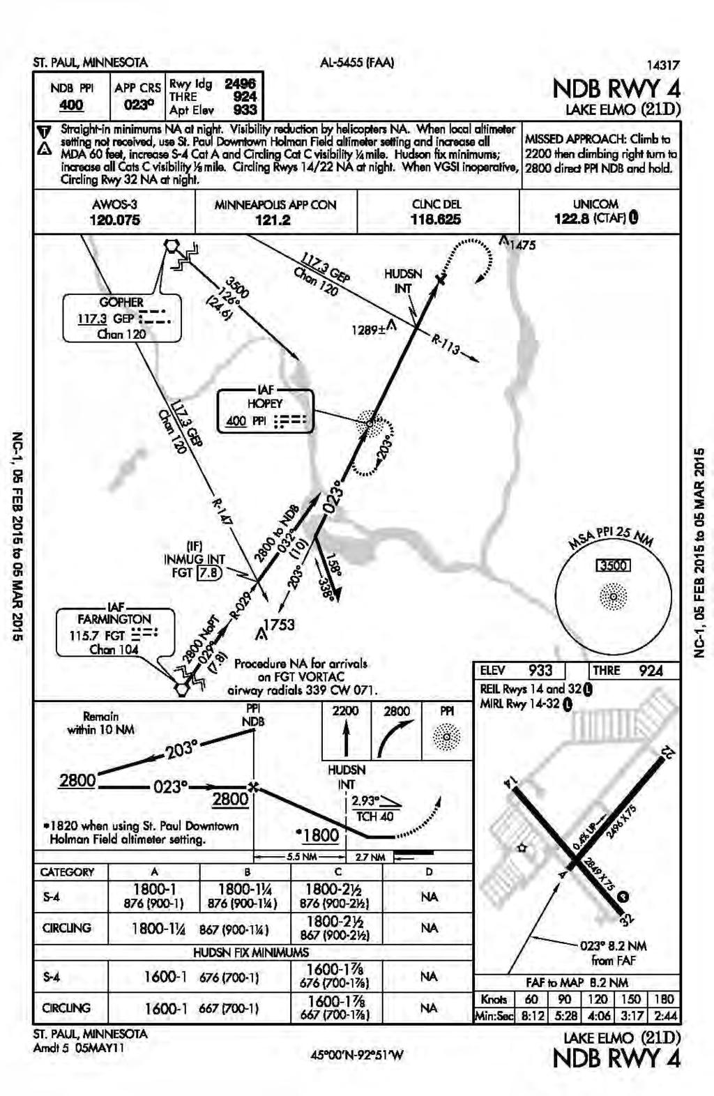
75 2-27

76 Figure 2-7: FAR Part 77 Airspace Surfaces 2-28

77 Figure 2-8: Building Areas 2-29
78 Figure 2-9: Conceptual Manning Avenue Realignment Corridor 2-30

79 Figure 2-10: Airport Drainage and Wetlands 2-31

80 Figure 2-11: Existing Off-Airport Land Use 2-32
81 SECTION 3: AVIATION FORECASTS
82 PAGE INTENTIONALLY LEFT BLANK
83 3. AVIATION FORECASTS 3.1 INTRODUCTION This chapter summarizes the LTCP activity forecast for Lake Elmo Airport. The base year is 2012 and forecasts were prepared for 2015, 2020, 2025, 2030, and The forecasts for the airport are unconstrained, except for runway length, and assume that the necessary facilities will be in place to accommodate demand. The chapter begins with a discussion of the forecasts for based aircraft and aircraft operations, and then concludes with a set of alternative forecast scenarios. The assumptions inherent in the following calculations are based on data provided by the MAC, federal and local sources, and professional experience. Forecasting, however, is not an exact science. Variances from assumptions related to the local and national economy and the aviation industry could have a significant effect on the forecasts presented herein. A summary of the methodology used to prepare the aviation activity forecasts is presented in Appendix 3. The complete Minneapolis-St. Paul Reliever Airport: Activity Forecasts Technical Report that contains full forecast development documentation can be downloaded from the MAC website at: HISTORICAL ACTIVITY LEVELS Based aircraft at Lake Elmo Airport increased during the 1990s and peaked at 245 aircraft in They gradually decreased to 203 in A number of factors have contributed to the slowdown since 2000, including the slowing economy, increased fuel prices and other operating costs, and reduced interest in recreational flying by younger generations. Table 3-1 summarizes historical based aircraft and aircraft operations at Lake Elmo Airport. Table 3-1: Historical Activity Levels Year Based Aircraft Aircraft Operations , , , , , , ,727 Source: MAC Records, HNTB Activity Forecasts 3-1
84 An inventory of specific aircraft based at Lake Elmo Airport according to MnDOT aircraft registration records is provided in Appendix 3. There is no Air Traffic Control Tower (ATCT) at Lake Elmo Airport, so there is no official count of aircraft operations. The existing level of aircraft operations at Lake Elmo Airport (25,727 annual or approximately 70 operations per day) was calculated as follows: The MAC Noise and Operations Monitoring System (MACNOMS) flight tracking system recorded 17,705 flight tracks for aircraft arriving to or departing from Lake Elmo Airport during The MACNOMS capture rate at all MAC-owned towered reliever airports (MACNOMS tracks compared to the official FAA Tower Count) for 2014 was 66.5%. The Anoka County-Blaine Airport (ANE) capture rate is 68.8%, and was used to adjust the Lake Elmo data set to account for missing flight tracks in MACNOMS. The MACNOMS capture rate adjustment for Lake Elmo is as follows: 17,705 MACNOMS recorded tracks / 68.82% ANE capture rate = 25,727 annual operations. This estimate is consistent with on-site observations conducted at the Airport during a two-week period in December 2011 and a one-week period in August Average daily aircraft operations were 52 in December and 87 in August. Monthly operations estimates for December 2011 and August 2012 were extrapolated using data from the towered reliever airports. A ratio of December and August operations as a percentage of the entire year was established using data from the towered reliever airports. This ratio was applied to the monthly estimates at Lake Elmo to estimate total 2012 operations (26,709). 3.3 SOCIOECONOMIC PROJECTIONS Population forecasts from the Metropolitan Council and per capita income forecasts from Woods & Poole Economics were used to develop hybrid income forecasts for each county in the metropolitan area. The income forecasts were used to estimate the share of based aircraft growth accounted for by each county. A summary of key socioeconomic projections for Washington County is provided in Table 3-2. Table 3-2: Washington County Socioeconomic Growth Trends Washington County Socioeconomic Indicator Change % Growth Population 250, , ,919 49% Employment 100, ,429 72,033 72% Real Personal Income $11,662,086 $22,237,099 $10,575,013 91% Per Capita Personal Income $46,581 $59,572 $12,991 28% Source: HNTB Activity Forecasts 3-2
85 A comparison of the projected socioeconomic indicator growth rates for Washington County versus Dakota County, the Seven-County Metropolitan Area, and the United States as a whole is presented in Table 3-3. Table 3-3: Comparison of Project Socioeconomic Growth Rates Socioeconomic Indicator Average Annual Growth Rates Washington Dakota 7-County County County Metro United States Population 1.8% 1.1% 1.1% 0.9% Employment 2.4% 1.7% 1.5% 1.3% Real Personal Income 2.8% 2.7% 2.7% 2.5% Per Capita Personal Income 1.1% 1.5% 1.6% 1.5% Source: HNTB Activity Forecasts Dakota County is included as a peer for comparison as there are several demographic similarities, and it is plausible that the operational composition at Lake Elmo Airport could evolve to become more like that existing at Airlake Airport in Lakeville. Based on this analysis, Washington County is expected to experience more robust growth in population, employment, and real personal income than its peers throughout the forecast period. These trends can be viewed as an overall positive indicator for the continued viability of aviation demand in the vicinity of Lake Elmo. 3.4 BASE CASE FORECAST Forecasts include based aircraft and operations for each major category: single-engine piston, multi-engine piston, turboprop, microjets 11, other jets, helicopters, and other 12. It was assumed that the share of each county s registered aircraft in each aircraft category based at each of the airports under study will remain constant. In the Base Case forecast scenario, the based fleet at Lake Elmo Airport is expected to decrease gradually by A decline in based single-engine piston aircraft will account for the decrease, with other categories either remaining the same or increasing slightly. Table 3-4 provides a summary of the based aircraft forecast. 11 Microjets, also referred to as very light jets or personal jets, refer to a category of small jet aircraft approved for single-pilot operation, typically seating 4-8 people, with a maximum takeoff weight of under 10,000 pounds. 12 The other category includes experimental and light sport aircraft types 3-3
86 Table 3-4: Summary of Based Aircraft Forecast (Base Case) Aircraft Category AAG Single-Engine Piston % Multi-Engine Piston % Turboprop % Microjets % Other Jets % Helicopter % Other % Total % Notes: AAG - Average Annual Growth Rate from 2012 to 2035 Source: HNTB Activity Forecasts Operations at Lake Elmo Airport are projected to decrease slightly from 26,709 in 2012 to 26,138 in 2035 in the Base Case, an average annual decrease of approximately 0.1 percent. Increases in operational levels are projected in all aircraft categories except single-engine pistons. Helicopters and other aircraft operations are projected to increase at a much faster pace than pistons and turboprops, consistent with the FAA s projections on active fleet and utilization of helicopter, single-engine piston, multi-engine piston, turboprop and other aircraft. Table 3-5 provides a summary of the aircraft operations forecast. Table 3-5: Summary of Aircraft Operations Forecast (Base Case) Aircraft Category Single-Engine Piston 23,189 21,664 20,092 19,802 20,946 21,823 Multi-Engine Piston Turboprop Microjets Other Jets Helicopter Other 2,899 3,176 3,304 3,276 3,388 3,450 Total 26,709 25,454 24,232 23,908 25,200 26,138 Notes: Other category includes experimental and light sport aircraft types Source: HNTB Activity Forecasts 3-4
87 Since Lake Elmo Airport does not have an air traffic control tower, the peak month percentage was estimated based on fuel flow records provided by the MAC. Based on these records, July is the peak month, accounting for approximately 13 percent of annual activity. Average Day Peak Month (ADPM) operations were estimated by dividing the peak month activity by 31 days. The peak hour operations percentage was obtained from field survey data. Approximately 12 percent of total operations occur during the peak hour. As depicted in Table 3-6, peak hour operations at Lake Elmo Airport are projected to be 13 operations. Table 3-6: Peak Period Forecasts Peak Periods Annual Operations 26,709 25,454 24,232 23,908 25,200 26,138 Peak Month Operations 3,339 3,182 3,029 2,988 3,150 3,267 ADPM Operations Peak Hour Operations Notes: ADPM - Average Day of the Peak Month Source: HNTB Activity Forecasts 3.5 FORECAST SCENARIOS Historically, general aviation activity has been difficult to forecast, since the relationships with economic growth and pricing factors are more tenuous than in other aviation sectors, such as commercial aviation. This uncertainty is likely to carry over into the near future, given the volatility of fuel prices and the continued emergence of microjets. To address these uncertainties, and to identify the potential upper and lower bounds of future activity at Lake Elmo Airport, Runway Extension, High, and Low forecast scenario developed. These scenarios use the same forecast approach that was used in the Base Case, but alter the assumptions to reflect either a more aggressive or more conservative outlook. The High Forecast scenario is based on the following assumptions: Income in each county is assumed to grow 50 percent more rapidly than under the Base Case. Fuel costs are assumed to follow the average of the U.S. Department of Energy low fuel price scenario and base case scenario. Increased popularity of light sport aircraft is assumed to grow 1.5 times more than the FAA forecast levels. This would increase the number of based aircraft and operations. 3-5
88 Other assumptions, including capacity constraints at Minneapolis-St. International Airport and St. Paul Downtown Airport are assumed to be the same as in the Base Case. The Low Forecast scenario was prepared using the following assumptions: Income in each county is assumed to grow 50 percent more slowly than under the Base Case. Fuel costs are expected to follow the U.S. Department of Energy high fuel price scenario. It is assumed that operators currently on waiting lists will become discouraged because of low income and high costs and choose to dispose of their aircraft or to remain at their existing location. Therefore, there would be no additional growth resulting from aircraft currently on waiting lists. Two extended runway scenarios were also prepared to evaluate the potential impact associated with runway lengthening under the Preferred Alternatives. Specifically, the first scenario assumes an extension of the primary runway at Lake Elmo Airport to an interim length of 3,300 feet, and the second scenario assumes an extension of the primary runway to an ultimate length of 3,600 feet. These runway extension scenarios assume that a longer runway at Lake Elmo Airport would attract additional business-related flights. Within the 3,600-foot runway extension scenario, the number of projected turbine 13 operations translates to approximately 11 aircraft takeoffs and landings per week by 2035, compared to approximately one per week in the Base Case scenario. Of the additional turbine aircraft operations, the majority (approximately two-thirds) are expected to be turboprops. With a longer runway in place, the increase in business-related flying is anticipated to largely offset the reduction in piston aircraft operations projected in the Base Case scenario. Table 3-7 compares the total number of aircraft and operations under different scenarios for Lake Elmo Airport. More detailed fleet mix tables for each forecast scenario are presented in Appendix Turbine aircraft operations include both turboprops and light jets 3-6
89 Table 3-7: Forecast Comparison by Scenario Scenario Based Aircraft Base Case High Range Low Range Extended Runway (3,300 ft. & 3,600 ft.) Aircraft Operations Base Case 26,709 25,454 24,232 23,908 25,200 26,138 High Range 26,709 29,322 30,128 32,460 35,610 39,119 Low Range 26,709 20,944 19,456 18,629 18,041 17,835 Extended Runway (3,300 ft.) 26,709 25,454 24,418 24,125 25,459 26,442 Extended Runway (3,600' ft.) 26,709 25,454 24,539 24,261 25,615 26,620 Source: HNTB Activity Forecasts 3.6 FORECAST SUMMARY Recent activity levels at Lake Elmo Airport (per Table 3.1) suggest that the number of based aircraft has declined slightly faster than predicted in the Base Case forecast scenario, but that aircraft operations are relatively stable. This indicates that the operations per based aircraft for those remaining at the airport are increasing. The forecast scenarios indicate that future economic growth, fuel prices, technology, and national aviation policy may have a major impact on the development of general aviation. An extension to the primary runway would also affect the forecasts, though not to the same extent as economic growth. Therefore, local economic trends and aviation activity levels should be monitored closely to identify any material variations from forecasted levels that would warrant adjustments to the long-term plan. FAA has reviewed and concurred with the Lake Elmo Airport activity forecasts per the letter reproduced in Appendix
90 PAGE INTENTIONALLY LEFT BLANK 3-8
91 SECTION 4: FACILITY REQUIREMENTS
92 PAGE INTENTIONALLY LEFT BLANK
93 4. FACILITY REQUIREMENTS 4.1 INTRODUCTION This chapter describes the facility requirements needed to accommodate the demand forecasts for year The sections of this chapter are intended to: Describe relevant design criteria Present airfield requirements in context of the critical aircraft Review NAVAID requirements Identify general aviation facility requirements Review parking and airport access needs Review obstructions issues Present miscellaneous requirements for the airport. 4.2 CRITICAL AIRCRAFT FAMILY DESIGN CRITERIA Based on the aviation activity forecasts, the future critical design aircraft for Lake Elmo Airport will continue to be represented by the family of propeller-driven aircraft with fewer than 10 passenger seats. This family of aircraft includes a diverse range of equipment types, ranging from small single-engine piston aircraft used primarily for recreational and personal flying up to larger single- and twin-engine turboprop aircraft that are used more predominantly for business aviation. Typical aircraft in the latter category include the single-engine turboprop Pilatus PC-12 and the twin-engine turboprop Beechcraft King Air 200. Figure 4-1 depicts several aircraft within this family by their Approach Category and Design Group, while Table 4-1 highlights physical characteristics for representative types. As with the existing condition, design parameters associated with this aircraft family will continue to be as follows: Aircraft Approach Category (AAC): A/B (approach speed less than 121 knots) Airplane Design Group (ADG): I/II (wingspan up to but not including 79 feet and tail height less than 30 feet) Taxiway Design Group (TDG): 2 (main landing gear width 20 feet or less and cockpit-to-main gear distance less than 64 feet) FAA airfield design standards for this family of critical aircraft are summarized in Table 2-2 of the Existing Conditions chapter. 4-1
94 Table 4-1: Representative Airplanes in Critical Aircraft Family Aircraft Type Configuration Wingspan Maximum Takeoff Weight (lbs.) Typical Passenger Seats Beechcraft King Air 200 MET 57' 11" 12, Pilatus PC-12 SET 53' 04" 10, Piper PA-31T Cheyenne MET 42' 08" 9, Cessna 421C MEP 41' 01" 7, Piper PA Chieftain MEP 40' 08" 7, Cessna 414A MEP 44' 01" 6, Cessna 310 MEP 36' 11" 5, Beechcraft Baron 58 MEP 37' 10" 5, Piper PA-30 Twin Comanche MEP 36' 00" 3, Notes: MET - Multi-Engine Turboprop, SET - Single-Engine Turboprop, MEP - Multi-Engine Piston Source: Aircraft Manufacturer Data 4.3 METEOROLOGICAL DATA AND RUNWAY ORIENTATION Weather conditions have a significant influence on the operational capabilities at an airport. Wind speed and direction help determine runway orientation. Temperature plays a role in determining runway length; higher temperatures in the summer months result in longer runway length requirements. Cloud cover and low visibility are factors used to determine the need for navigation aids and instrument approaches. Aircraft generally take off and land directly into the wind, or at least as directly into the wind as a given runway alignment allows. Crosswind runways are used when the wind is blowing perpendicular to the primary runway. Because small, single-engine aircraft have less power and are lighter than larger aircraft, they often have the most pressing need for crosswind runways. The FAA recommends that the primary runway provide at least 95 percent wind coverage for the aircraft anticipated to use the airport. If the primary runway does not provide this level of coverage, a crosswind runway may be justified. Because larger, heavier and more powerful aircraft need a crosswind runway less often than smaller, lighter and less powerful ones, different wind speeds are used in the crosswind runway analysis for different aircraft. These different wind speeds are called crosswind components. Crosswind components are defined by wind direction and speed taken at a right angle to a runway. Per FAA criteria, the maximum allowable crosswind component for Reference Code A/B- I aircraft is 10.5 knots and 13 knots for Reference Code A/B-II aircraft. 4-2
95 Available data from the Lake Elmo Airport Automated Weather Observation System (AWOS) installed in 2008 was obtained to analyze the amount of wind coverage provided by the current runway system. Table 4-2 summarizes the wind coverage of runways for the applicable crosswind components and weather conditions: Table 4-2: Wind Coverage Summary Wind Coverage All Weather Conditions VFR Conditions IFR Conditions 10.5 Kt. Crosswind Component Runway % 95.9% 95.3% Runway % 91.5% 95.1% Both Runways 99.2% 99.2% 99.4% 13 Kt. Crosswind Component Runway % 98.1% 97.6% Runway % 95.9% 97.8% Both Runways 99.9% 99.9% 99.9% Total Number of Hourly Observations 130, ,153 12,732 Notes: Bold numbers reflect 95% or greater wind coverage Source: 21D AWOS Wind Data This analysis indicates that the Runway alignment provides the desired 95 percent wind coverage for both crosswind component categories and during all weather conditions. The crosswind Runway alignment offers supplemental wind coverage so that the total runway system provides nearly 100 percent wind coverage. When considered on a stand-alone basis, the Runway alignment provides better wind coverage than the Runway alignment. An evaluation of wind rose data (see Figure 4-2) suggests that the strongest winds experienced at Lake Elmo Airport frequently come from a southwesterly direction. Runway 22 is particularly well aligned to accommodate aircraft operations during these high-wind conditions; furthermore, it is the only runway with a southwest/northeast orientation in the east metropolitan area to provide this wind coverage. Another important factor to consider when planning facilities at airports is temperature. The standard used is the mean daily maximum temperature of the hottest month at the Airport. For Lake Elmo Airport, the hottest month of the year is typically July. Based on long-term temperature trends available from National Climatic Data Center (NCDC) reporting stations in Saint Paul, Stillwater, and Hastings, the mean maximum daily temperature in the month of July is 83 F in the vicinity of Lake Elmo Airport. 4-3
96 4.4 AIRFIELD CAPACITY Airfield capacity is defined as the maximum number of operations that can be accommodated by a particular airfield configuration during a specified interval of time when there is constant demand. Annual service volume (ASV) is one capacity measure and the average hourly capacity is another. The Annual Service Volume (ASV) for a given airport is the annual level of aircraft operations that can be accommodated with minimal delay. For an airport with annual operations below its ASV, delay is minimal within one to four minutes per operation. Anything above four minutes of delay per operation can result in increased congestion that can adversely impact airfield capacity. An airfield system s capacity is determined by a multitude of various factors, including prevailing winds and associated orientation of runways, number of runways, taxiway system, fleet mix, operational characteristics of based aircraft and weather conditions. Lake Elmo Airport s ASV is currently estimated to be 230,000 operations annually, which is well above its current and projected future levels of annual operations. Even if the high forecast level of operations materializes (approximately 39,000), the airport will operate within its annual service volume. From the FAA Advisory Circular 150/ Airport Capacity and Delay, Lake Elmo Airport s average hourly capacity is estimated to be 98 operations during VFR conditions and 59 operations during IFR conditions. Peak activity forecasts show 13 peak hour operations for the year Thus, Lake Elmo Airport has adequate runway capacity to support all of the forecast scenarios. This means that additional runway capacity will not be a contributing factor to any airport improvements throughout the planning period. 4.5 AIRFIELD FACILITY REQUIREMENTS Runway Requirements The existing runways at Lake Elmo Airport are short. In comparison to the other MACowned Reliever Airports, both the primary and crosswind runways at Lake Elmo Airport are the shortest in the system. Runway length requirements are based on several factors, including the type of aircraft using or expected to use an airport, temperature, airport elevation, wind direction and velocity, and runway gradient. In addition, runway surface conditions also impact runway requirements. This last factor is an important consideration for determining runway lengths at airports in northern climates where wet and icy conditions exist. FAA Advisory Circular (AC) 150/5325-4B, Runway Length Requirements for Airport Design, recommends identifying a critical family of aircraft. Although this methodology is general in nature, it recognizes that there is uncertainty about the composition of the airport s fleet mix during the forecast period. Determining runway length based on an aircraft family ensures the greatest measure of flexibility. 4-4
97 As noted in Section 4.2, the future critical design aircraft for Lake Elmo Airport will continue to be represented by the family of propeller-driven aircraft with fewer than 10 passenger seats. Therefore, the design objective for the primary runway is to provide a runway length that will not result in operational weight restrictions for this family of aircraft. The corresponding Runway Design Code (RDC) for Runway will continue to be A/B-II-5, (small aircraft). According to the FAA, for airports with two or more runways, it is often desirable to design all airport elements to meet the requirements of the most demanding RDC and TDG. In order to preserve operational flexibility, the RDC for Runway will be designated as A/B-II-5,000 (small aircraft). Primary Runway Figure 2-1 in FAA Advisory Circular (AC) 150/5325-4B provides recommended runway lengths for propeller-driven airplanes with fewer than 10 passenger seats. The calculations consider airport elevation above mean sea level, mean daily maximum temperature of the hottest month and percentage of the overall fleet (family of aircraft) to be accommodated. A copy of this figure is reproduced in Appendix 4. Based on runway length guidance provided by the FAA AC, the appropriate runway length at the Lake Elmo Airport should be between 3,300 feet (to accommodate most of the aircraft types in this family, or 95% of the fleet) and 3,900 feet (to accommodate all types in the family, or 100% of the fleet). In the AC, the FAA states that if the fleet mix to operate at the airport is known, consult the manufacturer s literature to determine actual runway length requirements. To comply with this guidance, staff assessed manufacturer s performance charts from several representative aircraft types using, or expected to use, Lake Elmo Airport. The following conditions were assessed: Accelerate-stop distance (the runway length declared available and suitable for the acceleration and deceleration of an aircraft aborting a takeoff). Temperature of 83 F (the mean daily maximum temperature of the hottest month at the airport). Field elevation of 933 feet above mean sea level (AMSL). A 5-knot headwind. Typical takeoff flap settings. Table 4-3 summarizes takeoff length requirements for the representative aircraft types in the critical aircraft family for Lake Elmo Airport. Takeoff distance requirements are presented for several different takeoff weights representing percentages of the aircraft s total useful load 15. Representative aircraft performance charts used for this analysis are reproduced in Appendix ,000 feet corresponds to visibility minimums of not lower than one statute mile. 15 Useful load is defined as the aircraft maximum takeoff weight minus the aircraft empty weight. An aircraft s useful load can be used to transport either fuel or payload (passengers, baggage, and/or cargo). 4-5
98 Table 4-3: Takeoff Length Requirements Aircraft Type Maximum Takeoff Weight (lbs.) Takeoff Distance (ft.) for % Useful Load 100% 90% 75% 60% Beechcraft King Air ,500 3,700 3,600 3,400 3,200 Pilatus PC-12 10,450 3,900 3,700 3,400 3,000 Piper PA-31T Cheyenne 9,000 3,600 3,500 3,300 3,000 Cessna 421C 7,450 4,000 3,700 3,200 2,700 Piper PA Chieftain 7,000 3,700 3,600 3,300 3,100 Cessna 414A 6,750 4,600 4,300 3,700 3,200 Cessna 310 5,500 4,000 3,600 3,100 2,700 Beechcraft Baron 58 5,400 3,500 3,400 3,300 3,200 Piper PA-30 Twin Comanche 3,725 3,300 3,200 2,900 2,700 Average Length 3,811 3,622 3,289 3,013 Notes: Takeoff Distance based on Accelerate/Stop length from aircraft performance manuals. Takeoff distance calculations based on the following conditions: Temperature = 83 F, Field Elevation = 933 feet MSL, Wind = 5-knot headwind component, Flaps = Typical takeoff Source: Aircraft Performance Manuals/Data Based on this assessment, a suitable runway length for Lake Elmo Airport is approximately 3,600 feet. This runway length fits into the range provided by the FAA s AC guidance. It also suggests that a longer runway length of 3,900 feet as recommended in previous LTCPs for Lake Elmo Airport is not necessary to meet the objectives of enhancing safety and improving operational capabilities for the design aircraft family. A 3,600-foot long runway will accommodate the majority of small turboprop and multi-engine piston aircraft departing at a weight representing 90 percent of their useful load. Using the 90 percent of useful load criteria is considered appropriate given that aircraft in this family do not routinely need to depart at their maximum takeoff weight to complete a typical flight mission. The FAA establishes 75 feet as the required width for RDC A/B-II-5,000 runways. Runway is currently 75 feet wide. This width should be maintained in the future. It is envisioned that Runway will retain its current 14 CFR Part 77 Utility category for the foreseeable future and meet FAA design standards for small aircraft. Crosswind Runway The FAA acknowledges that even if the 95 percent crosswind coverage standard is achieved for the design airplane family, certain airplanes with lower crosswind capabilities may not be able to use the primary runway under all conditions. In these cases, a crosswind runway can be justified. The runway length for crosswind runways is based 4-6
99 on the recommended length for the lower crosswind capable airplanes using the primary runway. At Lake Elmo Airport, the lower crosswind capable aircraft include light single-engine aircraft used primarily for personal, recreational, and flight training activities. User input received during the planning process indicates that the existing crosswind runway length of 2,496 feet can be uncomfortably short for these lower crosswind capable aircraft during periods of gusty crosswind conditions. According to the MnDOT State Aviation System Plan (SASP), the minimal practical runway extension from a cost perspective is 250 feet. Lengthening Runway to 2,750 feet requires an extension of 254 feet. Any lesser extension would not likely prove to be cost effective. Runway is currently 75 feet wide, which meets design criteria for RDC A/B-II-5,000. It is recommended that the existing width of 75 feet be maintained throughout the planning period. It is envisioned that Runway will retain its current 14 CFR Part 77 Utility category for the foreseeable future and meet FAA design standards for small aircraft. Runway Separation Standards In the future, a minimum of 240 feet of separation should be provided between runways and parallel taxiways. This condition already exists on Runway 04-22, but not on existing Runway If the existing Runway configuration remains in place for the long term, formal FAA Modification to Design Standards will be sought to document the less than standard runway-to-taxiway separation condition. Runway Shoulders For RDC A/B-II-5,000, the required shoulder width is 10 feet. The airport provides 10- foot wide turf shoulders on both runways. All future conditions should continue to meet or exceed FAA standards. Runway Safety Areas, Object Free Areas, and Obstacle Free Zones The existing Runway Safety Areas (RSAs) and Runway Object Free Areas (ROFAs) at Lake Elmo Airport meet FAA standards for RDC A/B-II-5,000. All future conditions should continue to meet or exceed FAA standards. The existing ROFZs meet FAA requirements for the specified RDC for small aircraft. All future conditions should continue to meet or exceed FAA standards. Runway Protection Zones It is recommended that both runways maintain the current Runway Protection Zone (RPZ) dimensions for small aircraft in Approach Categories A/B (1,000 feet long with a 250-foot inner width and a 450-foot outer width). One of the goals for the 2035 LTCP is to comply with the FAA s airport design standards, so achieving RPZ compliance in the recommended future condition is a high priority. Reasonable efforts should be made to remove existing incompatible land uses from future 4-7
100 RPZs and to prevent new incompatible land uses from being introduced. In the event that incompatible land uses cannot be reasonably mitigated, or new incompatible uses are proposed, an RPZ Alternatives Analysis should be prepared and submitted to the FAA for the agency s concurrence to allow the incompatible land use to remain or be introduced. Runway Edge Lighting It is recommended that Medium-Intensity Runway Lights (MIRL) be added to Runway to enhance safety of operations and usability of the runway during nighttime hours and periods of low visibility, especially if a runway extension is constructed. Navigational Aids Currently, there is a PAPI system on Runway 32. It is recommended that a PAPI systems be added to the other three runways throughout the planning period. Currently, there are REILs on both ends of Runway It is recommended REILS be added to both ends of Runway as a part of any runway lighting project Taxiway Requirements As noted in Section 4.2, the existing and future critical design aircraft family for Lake Elmo Airport is within the parameters of the FAA s Taxiway Design Group (TDG) 2 (main landing gear width 20 feet or less and cockpit-to-main gear distance less than 64 feet). Taxiway Width The FAA design standard for TDG-2 width is 35 feet. The two parallel taxiways and all connector taxiways at Lake Elmo Airport are currently 30 feet wide, with the exception of a portion of the parallel taxiway to Runway 04-22, which is 40 feet wide. This means that most taxiways are deficient in width by five feet. As taxiway reconstruction projects become necessary, the MAC will widen the pavement to at least 35 feet and consider further widening to the MAC Reliever Airport standard of 40 feet. Taxiway Safety and Object Free Areas The existing Taxiway Safety Areas (TSAs) and Taxiway/Taxilane Object Free Areas (TOFAs) at Lake Elmo Airport meet or exceed FAA standards, with the exception of the conditions noted in Section All future conditions should meet or exceed FAA standards. Taxiway Shoulders Paved or stabilized shoulders are recommended along taxiways. TDG II aircraft require 15-foot stabilized shoulders. Lake Elmo Airport has 15-foot wide turf shoulders on its taxiways, which should be maintained. Taxiway Connectors Taxiway connectors should be present to facilitate efficient aircraft exit off of the supported runway, to reduce incursions and to minimize time on runway. The existing connectors currently provide this functionality and AC 150/ A, Change 1 guidance will be utilized for proposed future parallel taxiway extensions. 4-8
101 Taxiway Lighting Currently, taxiways at Lake Elmo Airport are unlit, nor do they have edge reflectors. It is recommended that taxiway edge reflectors be added to all of the taxiways at the airport. This would improve safety during the evening and after a light snowfall and also aid pilots who are unfamiliar with the airport. Furthermore, it is recommended that taxiway edge lighting be considered for installation on taxiways that are parallel to, or connect to, runways with edge lighting Instrument Approaches Runway 32 currently has an RNAV (GPS) approach with one-mile visibility minimums and Runway 04 has an NDB approach with one-mile visibility minimums. These are both nonprecision instrument approaches. Upgrading instrument approach capabilities to provide minimums of less than one mile are not contemplated with this plan due to the corresponding increase in the dimensions of the Runway Protection Zones that would have to be provided. Based on user input, development of a new, non-precision GPS-type instrument approach for Runway 14 and a GPS overlay of the existing non-precision approach for Runway 04 would enhance the operational capabilities of the airport without increasing the size of the Runway Protection Zones. Planning for the establishment of these nonprecision approaches with one-mile visibility minimums is recommended for consideration. GPS has made it possible to provide instrumentation to almost any runway end at relatively low cost because on-airport equipment is not required. 4.6 LANDSIDE FACILITY REQUIREMENTS Hangar Facilities Lake Elmo Airport, like all of the MAC airports, has a wide variety of hangar sizes. Over the years, the MAC has attempted to standardize the size of hangars within new hangar areas. However, aircraft also come in many different sizes, and trying to accommodate everyone leads to variability. As depicted in Table 2-6, Lake Elmo Airport is estimated to have 257 indoor aircraft storage spaces. This number includes an assumption that most airport tenants sublease extra space for additional aircraft within their hangars and includes a small discount for those who opt not to lease extra space. Tenants own their hangars and lease the ground space from the MAC. Currently, it is the MAC s policy that no tenant can lease more space than they can justify with actual aircraft ownership. This practice has reduced the number of large hangar demands, and subsequently, reduces some of the subleasing opportunities at the airport. According to the Base Case forecast results reported in Table 3-4, the number of based aircraft is anticipated to decline slightly through 2020 and then stabilize. By 2035, the number of based aircraft is forecasted to be 208 aircraft. The number of based aircraft reached a historical high in 1999 with 250 aircraft. The most recent hangar area expansion occurred in 1992, and was full by So, it appears that the space utilization calculation in Table 2-6 is reasonable, concluding that 4-9
102 257 aircraft can be accommodated in the existing building areas. According to the results of the Base Case forecast, no additional hangar spaces will be needed throughout the planning period. However, there could be demand for construction of certain hangar types and/or sizes that are not currently available. Additionally, the High Forecast scenario suggests that, given the right conditions, based aircraft could exceed 300 by Therefore, areas to accommodate the construction of additional hangars should be considered and preserved in the plan. The former FBO site in the West Building Area remains undeveloped and provides flexible space for construction of between seven and nine additional hangars, depending upon size and configuration. A conceptual layout for this site is shown in Figure 4-3. It is important to note that including additional hangar space in this LTCP is not a commitment to build or fund such a development. Rather, it is simply ensuring that should the indicated immediate demand lead to actual hangar construction, an appropriate place for them is shown in this plan and subsequent Airport Layout Plan. If a new hangar area is constructed, utility installations will be included in the project, including electricity, telephone/telecommunications, and natural gas. The issues related to sanitary sewer and water are discussed in Section Fixed Base Operator Consistent with the last LTCP, no additional space is needed at this time for a second FBO. The updated forecasts do not suggest that existing or anticipated future demand levels are sufficient to support more than one FBO facility at Lake Elmo Airport. Access to the FBO apron for aircraft should continue to be available from two directions to prevent congestion or head-to-head conflicts Airport Access, Roadway Circulation, and Parking At this time, airport access and parking facilities appear to be adequate. The two access roads connect to County Road 15 (Manning Avenue), which continues to see increases in the average daily traffic every year. As described in Section 2.4.4, Washington County is proposing to upgrade and improve Manning Avenue within the planning period. Both airport entrances should be maintained, as should the existing turning lanes. No internal vehicle service roads to connect the hangar areas are being considered at this time Maintenance and Fuel Storage Areas The existing MAC Maintenance facility is in excellent condition; however, the dimensions of the equipment bays may not be adequate to accommodate newer-generation snow removal equipment that in many cases are longer and taller than the older models. Modifications to the existing bays and/or a new bay may be needed to provide adequate storage space as older equipment is replaced. Also, an enclosed materials storage facility is already planned to store sand and other solid materials. There is ample space adjacent to the existing maintenance building for these improvements. 4-10
103 If the construction of a longer runway per the Runway Extension forecast scenario is considered, an area should be identified within the FBO leasehold to accommodate future jet fuel storage and its supporting dispensing infrastructure Security Requirements There is a fence that runs along the airport boundary on the west, south, and the southern end of the east side of the airport. The fence is not secured, as there are no gate closures preventing access to the main hangar areas at the airport. At this time, there is no demand or requirement for security related improvements at the airport. This should be monitored, however, in future long-term plan updates if there are any changes to national aviation security recommendations or if local issues generate a need for such improvements. If any of the airport s runways are extended in the future, the footprint of the perimeter fence should be extended to enclose the extent of the aircraft movement area. 4-11

104 Figure 4-1: Representative Aircraft Types in Critical Aircraft Family 4-12
105 Figure 4-2: Lake Elmo Airport All-Weather Wind Rose ( ) 4-13

106 Figure 4-3: West Building Area Hangar Development Concept 4-14
107 SECTION 5: ALTERNATIVES ANALYSIS
108 PAGE INTENTIONALLY LEFT BLANK
109 5. ALTERNATIVES ANALYSIS 5.1 INTRODUCTION Within this chapter, several potential development options are analyzed for Lake Elmo Airport. While the number of concepts could be infinite, those included in this chapter have been developed taking into consideration existing facilities, facility requirements, and forecasted activity levels. In addition, input received during the LTCP stakeholder outreach process will be considered. 5.2 DEVELOPMENT ALTERNATIVES CONSIDERED Evaluation Criteria The following criteria were used to evaluate airfield development alternatives: Maximizing Runway Protection Zone (RPZ) compatibility Ability to provide a length of at least 3,600 feet on the primary runway Maximizing primary runway wind coverage Maximizing use of existing airport property and facilities to minimize land acquisition Minimizing off airport land use and environmental impacts for existing and future developments Considering airspace and flight pattern implications in the vicinity of the airport Considering overall development cost Considering timing required to advance development Minimizing operational impacts during construction Base Case The first alternative is the Base Case, which maintains the existing airfield configuration and runway lengths. The primary focus of the Base Case would be to reconstruct existing runway and taxiway pavements as required to maintain operational capabilities throughout the planning period. Development associated with the Base Case is depicted in Figure 5-1. The FAA has indicated that acquisition of non-owned land interest in the Runway 14 RPZ will be a condition for the receipt of federal funding if Runway were to be reconstructed in the existing location. The Base Case alternative will not resolve the existing incompatible land uses in the Runway 14 and 32 RPZs. Therefore, an RPZ Alternatives Analysis of incompatible uses will be required to gain FAA approval for any future improvements to the runway or other triggering off-airport projects (e.g., Manning Avenue improvements). Advantages and disadvantages of the Base Case are summarized in the following table: 5-1
110 Base Case Advantages Disadvantages No changes to existing flight patterns Primary runway cannot be extended to the Retains use of existing north side end recommended 3,600-foot length taxiway Additional land acquisition required to Wind coverage maintained comply with FAA RPZ criteria No wetland mitigation required o Existing incompatible RPZ land uses No impact to existing 30 th Street N roadway are not addressed alignment o Improvements to the Manning Lowest development cost Avenue corridor will trigger an RPZ Alternatives Analysis Estimated Development Cost: $5,400,000 All development costs in this section are estimated in 2015 dollars and include reconstruction of existing Runway A breakout of estimated costs for each alternative is provided in Appendix Alternative A Alternative A considers extending the crosswind Runway to a length of 3,200 feet. Existing Runway would be maintained at its existing length and configuration. Development associated with Alternative A is depicted in Figure 5-2. Alternative A represents the Preferred Alternative from the LTCP approved in However, that plan was completed before the interim RPZ guidance from the FAA was released. As with the Base Case, retaining the existing Runway alignment will require that non-owned land in the Runway 14 RPZ be acquired under this alternative and an RPZ Alternatives Analysis will be required for Manning Avenue improvements. In addition, wind data available from the weather reporting station installed at Lake Elmo Airport in 2008 suggests that the crosswind runway alignment provides less favorable wind coverage than previously estimated based on regional, not site-specific, wind conditions. As shown in Table 4-2, the crosswind runway alignment does not provide at least 95 percent all-weather wind coverage with a 10.5 knot crosswind component as recommended by the FAA. Alternative A retains the previous LTCP recommendation to use standard-size Runway Protection Zones (RPZs) for Aircraft Approach Categories A/B (1,000 feet long with a 500-foot inner width and a 700-foot outer width) and an Other Than Utility designation on the primary runway. Advantages and disadvantages of Alternative A are summarized in the following table: 5-2
111 Alternative A Advantages Disadvantages Preferred Alternative from the previous LTCP Primary runway cannot be extended to the recommended 3,600-foot length Retains use of existing north side end taxiway Inadequate wind coverage on primary runway No impact to existing 30 th Street N roadway alignment Additional land acquisition required to comply with FAA RPZ criteria Low development cost when compared to other alternatives o Existing incompatible RPZ land uses are not addressed o Improvements to the Manning Avenue corridor will trigger an RPZ Alternatives Analysis o RPZ incompatibilities introduced on both ends of Runway Shifts existing traffic patterns and noise impacts to the northeast and southwest to align with lengthened crosswind runway alignment, moving the Runway 22 end closer to an established residential neighborhood Requires wetland mitigation Alternative B Estimated Development Cost: $7,700,000 Alternative B considers relocating the primary Runway and constructing it to a length of 3,600 feet. The relocation would include shifting the existing runway centerline approximately 700 feet parallel to, and northeast of, the existing alignment. Development associated with Alternative B is depicted in Figure 5-3. In order to attain the 3,600-foot length and comply with RPZ compatibility criteria, 30 th Street N must be realigned. This realignment can be accomplished on airport property, but requires a new intersection with Neal Avenue approximately ¼ mile to the south of the existing intersection between the roadways. Furthermore, the new Runway 14 end would be located south and east of the existing north side end taxiway, requiring that a portion of the existing taxiway be removed for airspace reasons. As a replacement, a new cross-field taxiway would be constructed to provide access to and from the new runway end. With the new cross-field taxiway, access to the FBO apron is available only from the east. As shown on the figure, construction of a by-pass taxilane near the FBO may be warranted to ensure efficient ingress and egress. Also, there is ample room adjacent to the existing fuel farm facility to expand it if warranted by demand. An additional recommendation of Alternative B is that the center 40 feet of existing Runway 14-32, upon decommissioning, be retained as a partial parallel taxiway to the new, relocated Runway This center section of pavement was rehabilitated in 2012 using state bonding funds. The grant with the state for use of these funds required MAC to commit to the terms of the agreement for 37 ½ years. Therefore, it is envisioned that 5-3
112 the rehabilitated center section of the existing runway will be kept in service throughout the planning horizon. The remaining outboard pavement sections of the existing runway not rehabilitated in 2012 will be removed. Portions of the existing parallel taxiway could revert to taxilane status or be considered for removal when rehabilitation is required. Although a parallel taxiway/taxilane system on the west side of the airport is not warranted from a capacity perspective, preserving the serviceable pavement section from the existing runway as a taxiway will enhance operational flexibility. Based on anticipated operational levels and development patterns throughout the planning horizon, the section of parallel taxiway on the north side of the relocated Runway and south of Runway is not considered to be part of the initial construction program for Alternative B. However, this section of parallel taxiway is identified as an ultimate feature that may become warranted by operational levels beyond the planning horizon or if demand for an east-side building area materializes. Alternative B retains the previous LTCP recommendation to use standard-size Runway Protection Zones (RPZs) for Aircraft Approach Categories A/B (1,000 feet long with a 500-foot inner width and a 700-foot outer width) and an Other Than Utility designation on the primary runway. It proposes clear RPZs for both Runways and and does not require land acquisition. It also allows for placement of a landside connector roadway between the north and west building areas, allowing access between them without accessing Manning Avenue. Advantages and disadvantages of Alternative B are summarized in the following table: Alternative B Advantages Disadvantages Runway RPZs comply with FAA compatibility criteria Relocation of 30th Street N will alter established traffic flows in the vicinity of the Development program can advance without airport the time needed for an RPZ Alternatives Analysis Existing north side end taxiway must be relocated No land acquisition required Shifts existing traffic patterns and noise Primary runway can be extended to the impacts to the southeast to align with the recommended 3,600-foot length relocated/lengthened primary runway, Runway alignment maintains moving the Runway 32 end closer to an adequate wind coverage established residential neighborhood Maintains continuity of existing airport Requires wetland mitigation operational footprint; primary runway Highest development cost remains on alignment New Runway can be constructed while existing Runway is in operation Alternative C Estimated Development Cost: $11,500,000 Alternative C also considers relocating primary Runway by shifting the centerline 700 feet to the northeast. However, in this alternative, the Runway 14 end would be 5-4
113 placed at the existing north side end taxiway and the runway would be extended to a length of 3,900 feet. Development associated with Alternative C is depicted in Figure 5-4. Alternative C represents the legacy alternative that has been shown on previous Airport Layout Plans for Lake Elmo Airport for many years. As with Alternative B, 30 th Street N must be realigned to remain clear of the RPZ. However, to maximize runway length, several incompatible land uses will remain in the Runway 14 RPZ, including the north entrance drive, the railroad, and a portion of Manning Avenue. As this is a new runway, an RPZ Alternatives Analysis will be required to study the impacts of these incompatible uses and gain FAA approval. As with Alternative B, it is recommended that the center 40 feet of the existing Runway pavement be retained as a partial parallel taxiway to the new primary runway. Also, the section of parallel taxiway on the north side of the relocated Runway and south of Runway is not considered to be part of the initial construction program for Alternative C, but will be shown as ultimate development. Alternative C retains the previous LTCP recommendation to use standard-size Runway Protection Zones (RPZs) for Aircraft Approach Categories A/B (1,000 feet long with a 500-foot inner width and a 700-foot outer width) and an Other Than Utility designation on the primary runway. Advantages and disadvantages of Alternative C are summarized in the following table: Advantages Primary runway can be extended to 3,900 feet, the longest of any alternative, but beyond the recommended length of 3,600 feet identified in the facility requirements analysis Runway alignment maintains adequate wind coverage Retains use of existing north side end taxiway No land acquisition required Maintains continuity of existing airport operational footprint; primary runway remains on alignment New Runway can be constructed while existing Runway is in operation Alternative C Estimated Development Cost: $10,600, th Street N Realignment Alternatives Disadvantages Incompatible land uses in the Runway 14 RPZ require an RPZ Alternatives Analysis Relocation of 30th Street N will alter established traffic flows in the vicinity of the airport Shifts existing traffic patterns and noise impacts to the southeast to align with the relocated/lengthened primary runway, moving the Runway 32 end closer to an established residential neighborhood Requires wetland mitigation High development cost As noted above, both Alternatives B and C require relocation of 30 th Street N to route it clear of the relocated Runway 32 end RPZ. 5-5
114 Three alternative alignments have been identified for this roadway relocation, as presented in Figure 5-5. The alternative alignments are described more fully below. Realignment Alternative 1: This alternative realigns 30 th Street N to the southeast of the relocated Runway 32 end RPZ so that it intersects with Neal Avenue approximately ¼-mile south of the existing intersection. The design speed for the relocated roadway is 45 miles per hour. With this alignment option, thru traffic on 30 th Street N would experience two additional turning movements in each direction and an increase in total travel distance (about 1,800 feet). Also, 30 th Street N thru traffic would be introduced onto the segment of Neal Avenue between the intersections. Conversely, local traffic flowing between Manning Avenue and residential developments to the south of the new intersection would be removed from this segment of Neal Avenue and benefit from a reduced travel distance. Alternative 1 represents the lowest cost option. Realignment Alternative 2: This alternative realigns 30 th Street N around the end of the relocated Runway 32 end RPZ but continues the curve to the north so that the roadway reconnects at the existing Neal Avenue alignment and intersection. Access to existing Neal Avenue south of the realigned area would be maintained through construction a new T intersection. The design speed for the relocated roadway is 45 miles per hour. With this alignment option, thru traffic on 30 th Street N would experience one additional turning movement in each direction and an increase in total travel distance (about 1,500 feet). Compared to Realignment Alternative 1, 30 th Street N traffic would be introduced onto a shorter segment of the existing Neal Avenue alignment. Impacts to local traffic flowing between Manning Avenue and residential developments to the south of the new intersection are similar to those in Alternative 1. Alternative 2 represents the highest cost option. Realignment Alternative 3: This alternative maintains the existing intersection at 30 th Street N and Neal Avenue; the realigned roadway curves around the relocated Runway 32 end RPZ. Due to the tighter curves, the design speed for the relocated roadway is reduced to 30 miles per hour. With this alignment option, there are no new intersections or turning movements for thru traffic on 30 th Street N and no new traffic is introduced onto Neal Avenue. However, this alignment does not allow for the relocated Runway to be extended to its recommended length of 3,600 feet as proposed in Alternative B. 5.3 SELECTION OF THE FINAL LTCP PREFERRED ALTERNATIVE After reviewing the concepts, costs, advantages and disadvantages, Alternative B was identified as the Original Preferred Development Alternative for Lake Elmo Airport. However, the realignment of 30th Street N and establishment of a new intersection at Neal Avenue as proposed in Alternative B generated significant resistance from area residents during the first round of public comment. Based on this feedback, MAC staff re-evaluated options to connect 30 th Street N back up to its existing intersection with Neal Avenue while still remaining clear of the Runway Protection Zone (RPZ). Based on this evaluation, a refined, scaled-back version of 5-6
115 Alternative B was prepared to address some of the community s concerns in a manner that continued to meet the stated planning objectives. The refined concept was labeled Alternative B1. When compared with the original concept, Alternative B1 includes the following adjustments: Runway length: The refined concept includes a shorter runway length (3,500 feet versus 3,600 feet). Although 100 feet shorter than the optimal length of 3,600 feet, staff believes a 3,500-foot runway is a viable improvement over the existing condition. The slightly shorter runway also reinforces the MAC s intent of not changing the role of the airport or the types of aircraft that will utilize it. Runway designation: The refined concept reverts to a Utility runway designation allowing use of smaller-dimension Runway Protection Zones (RPZs) on the primary runway. Both runways at Lake Elmo Airport are currently designated as Utility, meaning that they are constructed for, and intended to be used by, propeller-driven aircraft of 12,500 pounds maximum gross weight and less. This runway designation does not preclude occasional operations by small jet aircraft. Runway location: The combination of a shorter runway length and smallerdimension RPZs allows the runway alignment to be closer to the existing runway, with the north end sited to keep the RPZ clear of the railroad track th Street N Realignment: With these adjustments, the relocation of 30 th Street N can be routed around the new RPZ and meet back up with Neal Avenue at its existing intersection (using Realignment Alternative #3). Vehicle traffic patterns therefore would not be altered on Neal Avenue. The possibility of right-of-way taking from properties located along Neal Avenue also is eliminated. The improvements associated with the Alternative B1 are shown in Figure 5-6. Advantages and disadvantages of Alternative B1 are summarized below. 16 FAA has given approval to keep the north airport entrance driveway within the Runway Protection Zone (RPZ) to facilitate this shift. 5-7
116 Alternative B1 (Refined Preferred Alternative) Advantages Disadvantages Runway RPZs comply with FAA compatibility criteria Realignment of 30th Street N will slightly increase average travel times between No RPZ Alternatives Analysis required Manning Avenue and Neal Avenue No land acquisition is required Existing north side end taxiway and Existing intersection of 30th Street N and compass calibration pad must be relocated Neal Avenue is maintained. When compared with the existing runway, Primary runway can be extended to 3,500 feet still within the FAA s guidelines to accommodate most, but not all, of the design the new runway configuration shifts existing aircraft traffic patterns and noise impacts to the southeast, moving the Runway 32 end aircraft family closer to an established residential Runway alignment maintains neighborhood adequate wind coverage May require wetland mitigation Maintains continuity of existing airport operational footprint; primary runway remains on alignment New Runway can be constructed while existing Runway is in operation Potential for less impact on the wetland area located north of 30th St N and northeast of the relocated runway Estimated Development Cost: $11,500, o Potential for greater impact on the existing wetland area north of 30th Street N and west of the relocated runway Highest development cost of concepts considered On December 21, 2015, the (MAC) Board approved staff s recommendation to update the Draft 2035 LTCP by replacing the Original Preferred Alternative (Alternative B) with the refined, scaled-back concept (Alternative B1) and initiate a supplemental public comment period. After reviewing the body of public comments received during both the initial and supplemental public comment periods 18, including those opposed and those supporting the proposed improvements, MAC staff prepared a recommendation to the Board that the refined concept be approved as the Final Preferred Development Alternative for Lake Elmo Airport 2035 LTCP on the basis that it addresses Runway Protection Zone safety compliance, provides planning certainty for the surrounding communities and jurisdictions, and addresses a long-standing runway length deficiency in a responsible manner, taking into account all considerations and input. The MAC Board approved staff s recommendation of the Final Preferred Development Alternative on April 18, The estimated cost of the Refined Preferred Alternative is expected to remain the same as the Original Preferred Alternative. See Section 8.2 for cost estimate information. 18 See Section 8.4 for more information about the LTCP stakeholder engagement and public information process. All public comments received are published in Appendix
117 In summary, the Final Preferred Development Alternative proposes the following improvements for the 20-year planning period: Relocate primary Runway by shifting the centerline 615 feet to the northeast and extend it to a length of 3,500 feet, including all necessary grading and clearing Realign 30 th Street N around the new Runway 32 end RPZ and reconnect to the existing intersection with Neal Avenue Construct a new cross-field taxiway to serve the new Runway 14 end, including taxiway lighting and/or reflectors Convert existing Runway into a partial parallel taxiway and construct additional taxiway infrastructure as needed to support the relocated runway, including taxiway lighting and/or reflectors Reconstruct existing crosswind Runway and extend it to 2,750 feet as recommended in the facility requirements section, including runway lighting, Precision Approach Path Indicator (PAPI) systems, and a new taxiway connector Pursue the establishment of a new non-precision instrument approach to the Runway 14 end, and upgrade the existing Runway 04 approach to an RNAV (GPS) type The Final Preferred Alternative was selected for the following reasons: It provides compatible RPZs entirely on airport property for the replacement Runway It provides a runway length of 3,500 feet, which is a suitable length to accommodate the design aircraft family After the 3,500-foot length is constructed, the primary runway will be fully builtout in terms of RPZ compliance, with no further extensions contemplated during the 20-year planning horizon. This will give the surrounding municipalities assurance of the airport s future footprint for comprehensive community planning. It maintains the continuity of the existing operational footprint as the primary runway remains on the alignment. This ensures optimal wind coverage as well. It optimizes the use of existing airport property, including that purchased in the late 1960s and 1970s for the runway relocation and realignment of 30 th Street N. No additional property acquisition is required. It accommodates the future expansion needs of County State Aid Highway 15/Manning Avenue in its current alignment. Urban development is expected to increase west of Lake Elmo Airport and adjacent to this portion of Manning Avenue which will need to be expanded in the next decade to accommodate current and expected future traffic. It minimizes operational disruptions during construction as the replacement Runway can be constructed with the existing Runway in operation. 5-9
118 It is consistent with the long-term vision for the airport, which has included a relocated and longer primary runway for many years. Some additional factors warrant consideration in future airport plans. Although additional hangar space is not anticipated to be needed within the planning horizon, preserving the former FBO site in the West Hangar Area for future development is recommended. Also, existing airport property that could be transitioned into non-aeronautical revenue generating land uses should be preserved. Finally, it is important to note that the LTCP is a planning document and does not authorize any construction. Adoption of the LTCP is only the first step in the project implementation process. Before any construction can begin, the project(s) must first be evaluated through an environmental review process and then compete for funding through Federal Aviation Administration and/or State grant programs. In order to compete effectively for funding, the project(s) must have solidly documented justification. Once funding is secured, final project engineering and design will take approximately one year to complete. Based on this timeline, it is feasible that construction could occur sometime in the timeframe (subject to change). 5-10
119 Figure 5-1: Base Case Alternative Layout 5-11
120 Figure 5-2: Alternative A Layout 5-12
121 Figure 5-3: Alternative B Layout 5-13
122 Figure 5-4: Alternative C Layout 5-14

123 Figure 5-5: 30th Street N Relocation Alignment Alternatives 5-15
")
124 Figure 5-6: Alternative B1 (Final Preferred Alternative) 5-16
125 SECTION 6: ENVIRONMENTAL CONSIDERATIONS
126 PAGE INTENTIONALLY LEFT BLANK
127 6. ENVIRONMENTAL CONSIDERATIONS 6.1 INTRODUCTION An integral part of the airport planning process focuses on the manner in which the airport and any planned enhancements to the facility pose environmental impacts. This chapter provides a high-level introductory assessment of potential environmental implications of the planned operation and development of Lake Elmo Airport. Prior to any construction taking place, the MAC will complete an Environmental Assessment (EA) and/or an Environmental Assessment Worksheet (EAW) to meet Metropolitan Council guidelines and FAA requirements for utilizing Airport Improvement Program (AIP) grant funds. 6.2 AIRCRAFT NOISE Quantifying Aircraft Noise Basics of Sound Sound is a physical disturbance in a medium; a pressure wave typically moving through a fluid - air. A sound source vibrates or otherwise disturbs the air immediately surrounding the source, causing variations in pressure above and below the static (at-rest) value of atmospheric pressure. These disturbances force air to compress and expand setting up a wavelike movement of air particles that move away from the source. Sound waves, or fluctuations in pressure, vibrate the eardrum creating audible sound. The decibel, or db, was introduced as a measure of sound pressure level that is compressed into a convenient range, the tremendous span of human sensitivity to pressure. Using a logarithmic relationship, and the ratio of sensed pressure compared against a fixed reference pressure value, the db scale accounts for the range of hearing with values from 0 to around 200. Most human sound experience falls into the 30 db db range. Decibels are logarithmic, and thus cannot be added directly. Two identical noise sources each producing 70 db do not add to a total of 140 db, but to 73 db. Each time the number of sources is doubled, the sound pressure level is increased 3 db. 2 sources: 70 db + 70 db = 73 db 4 sources: 73 db + 73 db = 76 db 8 sources: 76 db + 76 db = 79 db The just-noticeable change in loudness for normal hearing adults is about 3 db. That is, changes in sound level of 3 db or less are difficult to notice. A doubling of loudness for the average listener of A-weighted sound is about 10 db 19. Measured, A-weighted sound levels changing by 10 dba effect a subjective perception of being twice as loud. 20 Figure 6-1 provides the noise levels for various common sources. 19 A-weighted decibels represent noise levels that are adjusted relative to the frequencies that are most audible to the human ear. 20 Peppin and Rodman, Community Noise, p ; additionally, Harris, Handbook, Beranek and Vér, Noise and Vibration Control Engineering, among others. 6-1
128 Day-Night Average Sound Level (DNL) In 1979 the United States Congress passed the Aviation Safety and Noise Abatement Act. The Act required the Federal Aviation Administration (FAA) to develop a single methodology for measuring and determining airport noise impacts. In January 1985 the FAA formally implemented the Day-Night Average Sound Level (DNL) as the noise metric descriptor of choice for determining long-term community noise exposure in the airport noise compatibility planning provisions of 14 C.F.R. Part 150. Additionally, FAA Order , Environmental Impacts: Policies and Procedures and FAA Order , National Environmental Policy Act (NEPA) Implementing Instructions for Airport Actions, outline DNL as the noise metric for measuring and analyzing aircraft noise impacts. As detailed above, the FAA currently requires the DNL noise metric to determine and analyze noise exposure and aid in the determination of aircraft noise and land use compatibility issues around United States airports. Because the DNL metric correlates well with the degree of documented community annoyance from aircraft noise, DNL has been formally adopted by most federal agencies dealing with noise exposure. In addition to the FAA, these agencies include the U.S. Environmental Protection Agency (EPA), U.S. Department of Defense, U.S. Department of Housing and Urban Development, and Veterans Administration. The DNL metric is calculated by cumulatively averaging sound levels over a 24-hour period. This average cumulative sound exposure includes the application of a 10-decibel penalty to sound exposures occurring during the nighttime (10:00 PM to 7:00 AM). The night sound exposures are increased by 10 decibels because nighttime noise is more intrusive. Figure 6-2 provides examples of typical DNL levels in various environments. The FAA currently considers the 65 db DNL contour line as the threshold of significance for noise impact. As such, sensitive land use areas (e.g., residential) around airports that are located in the 65 db or greater DNL contours are considered by the FAA as incompatible structures. Integrated Noise Model (INM) The FAA s Integrated Noise Model (INM) version 7.0d was used for evaluating aircraft noise impacts in this plan. The model utilizes flight track information, runway use information, operation time of day data, aircraft fleet mix, standard and user defined aircraft profiles, and terrain as inputs. The INM model produces DNL noise exposure contours that are used for land use compatibility maps. The INM considers multiple airport and aircraft operational and noise propagation variables. The primary inputs into the model include aircraft activity levels, fleet mix, day/night split of operations, runway use and flight tracks. The noise analysis contained in this plan was completed prior to the FAA s release of the Aviation Environmental Design Tool (AEDT). Noise analyses conducted after this release will use AEDT. 6-2
129 6.2.2 Noise Contour Development The noise contours presented in this document were developed using INM Version 7.0d. The contours represent noise contours, expressed in DNL. The FAA currently suggests that three different DNL levels (65, 70, and 75 DNL) be modeled but considers the 65 db DNL contour line as the threshold of significance for noise impact. The Metropolitan Council suggests that the 60 DNL contour be included for airports in an urban environment and the 55 DNL in cases where airports are located outside the Metropolitan Urban Service Area (MUSA). Lake Elmo Airport currently lies outside of the MUSA, so the 55 DNL noise contour will be shown for advisory purposes. However, it is not linked to any requirements for noise attenuation or mitigation. The (MAC) owns and operates a Noise and Operations Monitoring System (MACNOMS) at Minneapolis-St. Paul International Airport (MSP). In addition to monitoring noise levels at 39 remote noise monitoring towers located around MSP, the system collects flight track data to approximately 40 miles around MSP up to 20,000 feet. Lake Elmo Airport is located approximately 18 miles from MSP. As such, flight track data in the vicinity of Lake Elmo Airport were provided by MACNOMS to aid in the INM input file development process. MACNOMS flight track data from the 12-month period ending in October 2014 were adjusted to equal the Base Case Year 2012 operations estimates (26,709 aircraft operations) to develop the Baseline Condition INM Inputs. Due to the existing constraints in the flight tracking system in the vicinity of Lake Elmo Airport, acquisition and availability of detailed flight track data is reduced. However, for the year ending October 2014, MACNOMS reported approximately 18,000 aircraft operations in the vicinity of Lake Elmo Airport, which represents approximately 2/3 of total estimated operations. See Section 3.2 for more information about the MACNOMS flight track data for Lake Elmo Airport. This provided an adequate data sample for purposes of contributing to the construction of the INM inputs. The following details the methodology utilized in developing the data inputs for the INM contour modeling. Aircraft Activity Levels As summarized in Table 3-7 in Chapter 3, the total number of Lake Elmo Airport operations in the 2012 Baseline Condition is estimated to be 26,709 and the 2035 Final Preferred Alternative Condition forecast number of total operations is 26,620, which is established per the 3,600-foot runway extension scenario forecast. Even though the Final Preferred Alternative includes a shorter runway length of 3,500 feet, the same number of aircraft operations will be used for noise modeling purposes as a conservative approach. Fleet Mix Using the MACNOMS flight track data available in the vicinity of Lake Elmo Airport for a 12-month period ending October 2014, various data processing steps were taken to develop the Baseline Condition fleet mix. The flight track analysis process began by first excluding all MSP air carrier jet flight tracks. Then all flight tracks with a start point or end point that did not fall within a 5km (3.1 mile) radius and 1km (0.6 mile) ceiling (above ground level) around Lake Elmo Airport were filtered out of the data. If the starting point of a track was within the radius and ceiling thresholds, it was considered a departure 6-3
130 operation. If the endpoint of a track was within the radius and ceiling thresholds, it was considered an arrival operation. If both start and end points of a track were within the radius and ceiling thresholds, it was considered a touch and go operation. The aircraft type information from the MACNOMS flight track system was then adjusted to reflect the number of operations per aircraft category from the Base Case Year 2012 operations estimates, as described in Appendix 3 to develop the Baseline Condition fleet mix. The Baseline Condition fleet mix was then scaled to reflect the forecast assumptions outlined in Chapter 3 to arrive at the projected Forecast 2035 fleet mix. A summary of the Baseline Condition and Forecast 2035 fleet mixes is provided in Table 6-1. A more detailed presentation of the Baseline Condition and 2035 Preferred Alternative Condition aircraft fleet mixes is provided in Appendix 6. Day/Night Split of Operations Based on the MACNOMS flight track data for Lake Elmo Airport, the split of day and nighttime operations was determined. Daytime hours are defined as 7:00 AM to 9:59:59 PM and nighttime hours are 10:00 PM to 6:59:59 AM. The day/night operations distribution derived from the MACNOMS flight track data was then applied to the total number of operations to develop the Baseline Condition day/night split. The Baseline Condition day/night split was used to arrive at the 2035 Final Preferred Alternative Condition day/night split. The day/night split is not expected to change significantly throughout the forecast period. A summary of the Baseline Condition and 2035 Final Preferred Alternative Condition day/night splits is also provided in Table 6-1. A more detailed presentation of the Baseline Condition and 2035 Final Preferred Alternative Condition day/night splits is provided in Appendix
131 Table 6-1: Summary of Average Daily Flight Operations Average Daily Flight Operations Day Night Total % of Total Operations Baseline Condition Helicopter % Multi-Engine Piston % Single-Engine Piston % Turboprop % Jet % Total % % of Total Operations 96.8% 3.2% 100.0% 2035 Final Preferred Alternative Condition Helicopter % Multi-Engine Piston % Single-Engine Piston % Turboprop % Jet % Total % % of Total Operations 96.5% 3.5% 100.0% Notes: Totals may not add due to rounding Source: MACNOMS Data Analysis, HNTB Activity Forecasts Runway Use Using the Lake Elmo Airport flight track data, a runway use analysis was conducted. Runway assignments were made utilizing trapezoids off the end of each runway to determine on which runway a flight operated. Each trapezoid runs along the axis of the centerline beginning at the runway end and extending 5km (3.1 miles). The trapezoid is 0.4km (.25 miles) wide at the runway end and 2km (1.2 miles) wide at the extent furthest from the runway. For the purpose of the runway use analysis, the last five or first five data points of each flight track in the vicinity of Lake Elmo Airport were analyzed relative to the runway trapezoids. In cases when the last five radar points of a track were in the vicinity of Lake Elmo Airport, and at least one of the radar points was located within a respective runway trapezoid, the track was assigned as an arrival operation on that runway. Conversely, in cases when the first five radar points were in the vicinity of Lake Elmo Airport, and at least one of the radar points was located within a respective runway trapezoid, the track was assigned as a departure operation on that runway. In cases when the last five and first five radar points were in the vicinity of Lake Elmo Airport, and at least one of the last and at least one of the first radar points were located within a respective runway trapezoid, the track was assigned as a touch and go operation on the respective runway(s). 6-5
132 The Baseline Condition runway use assumptions were then adjusted to arrive at the projected 2035 Final Preferred Alternative runway use. All new turbine aircraft operations are assigned to Runway and a greater share of piston-powered aircraft are assigned to Runway due to its planned extension and installation of runway lights. A summary of the Baseline Condition and 2035 Preferred Alternative Condition runway use percentages is provided in Table 6-2. A more detailed presentation of the Baseline Condition and 2035 Preferred Alternative Condition runway use is provided in Appendix 6. Flight Tracks The Baseline Condition INM flight track locations were developed based on the trends established by the MACNOMS flight tracks that met the fleet mix data sample criteria for Lake Elmo Airport. The Baseline Condition INM flight tracks were then adjusted to reflect the new runway ends per the Final Preferred Alternative. Specifically, Runway was shifted approximately 615 feet to the northeast and extended to the southeast to an ultimate length of 3,500 feet and Runway was extended to the northeast for a total runway length of 2,750 feet, as detailed in Chapter 5. Figures depicting flight track locations and additional detail related to flight track use for the Baseline and 2035 Final Preferred Alternative Conditions are provided in Appendix
133 Table 6-2: Summary of Average Annual Runway Use Arrivals Departures Touch and Gos Average Annual Runway Use % Day Night Total Day Night Total Day Night Total Baseline Condition Runway 4 5.4% 5.5% 5.4% 8.1% 4.2% 8.0% 6.5% 0.0% 6.5% Runway % 27.8% 27.3% 32.5% 50.6% 33.1% 29.1% 33.3% 29.2% Runway % 15.9% 19.0% 15.9% 12.6% 15.8% 19.1% 3.0% 18.9% Runway % 50.9% 48.3% 43.5% 32.6% 43.2% 45.3% 63.6% 45.5% 2035 Final Preferred Alternative Condition Runway 4 8.8% 9.7% 8.8% 10.4% 8.9% 10.4% 10.2% 8.0% 10.1% Runway % 30.0% 25.6% 30.2% 36.0% 30.4% 25.6% 27.0% 25.6% Runway % 19.4% 20.4% 18.6% 20.2% 18.6% 23.7% 25.0% 23.7% Runway % 40.9% 45.2% 40.8% 34.8% 40.6% 40.5% 40.0% 40.5% Notes: Totals may not add due to rounding Source: MACNOMS Data Analysis 6-7
134 6.2.3 Baseline Condition Noise Impacts In the Baseline Condition noise contours there are no residential structures located within the 60 or greater DNL contours around Lake Elmo Airport. The 55 DNL contour contains approximately acres and two single-family structures. The 60 DNL contour contains approximately 99.8 acres. The 65 DNL contour contains approximately 58.6 acres with most of the 65 DNL contour on airport property (residential structures are typically considered incompatible within the 65 DNL noise contour). The entire 70 and 75 DNL contours are contained on the airport property, essentially overlying the areas immediately adjacent to the runways. The 70 and 75 DNL contours contain 37.9 and 9.9 acres respectively. The Baseline Condition noise contours are shown in Figure 6-3. A summary of the Baseline Condition noise impact is provided in Table 6-3. Table 6-3: Baseline Condition Noise Impact Summary Noise Impact Summary by Contour 75 DNL 70 DNL 65 DNL 60 DNL 55 DNL Baseline Condition Contour Overall Area (Acres) Contour Contained on Airport? Yes Yes No No No Number of Residential Structures Notes: Structure count does not include future residential homes in Easton Village development Source: MAC Analysis Final Preferred Alternative Condition Noise Impacts In the 2035 Final Preferred Alternative noise contours, there are no residential structures located within the 60 or greater DNL contours around Lake Elmo Airport. The 55 DNL contour contains approximately acres and 13 single-family structures. The 60 DNL contour contains approximately acres with the entire 60 DNL contour contained on airport property. The 65 DNL contour contains approximately 71.4 acres. The 70 and 75 DNL contours contain 41.3 acres and 12.6 acres, respectively. The 2035 Final Preferred Alternative noise contours are shown in Figure 6-4. A summary of the Forecast 2035 Preferred Alternative noise impact is provided in Table
135 Table 6-4: 2035 Final Preferred Alternative Condition Noise Impact Summary Noise Impact Summary by Contour 75 DNL 70 DNL 65 DNL 60 DNL 55 DNL 2035 Refined Preferred Alternative Contour Overall Area (Acres) Contour Contained on Airport? Yes Yes Yes Yes No Number of Residential Structures Notes: Structure count does not include future residential homes in Easton Village development Source: MAC Analysis A comparison of the Baseline, Original Preferred Alternative, and Final Preferred Alternative noise contours is shown in Figure 6-5. Table 6-5 provides a comparison of noise impacts from the Baseline to the 2035 Refined Preferred Alternative Condition. Table 6-5: 2035 Changes in Noise Contours (Baseline to 2035 Final Preferred Alternative) Noise Impact Comparison by Contour 75 DNL 70 DNL 65 DNL 60 DNL 55 DNL Change from Baseline to 2035 Final Preferred Alternative Conditions Contour Overall Area Change (Acres) Percentage Change -45% 13% 24% 9% -4% Number of Residential Structures Notes: Structure count does not include future residential homes in Easton Village development Source: MAC Analysis In summary, when the 2035 Final Preferred Alternative Condition contours are compared to the Baseline (existing) Condition contours: For the 65 DNL contour, the acreage contained within the contour increases by 24 percent, with no residential parcels contained in the contour under either condition. The 65 DNL contour extends off the airport property in the Baseline Condition but is contained on airport property in the Refined Preferred Alternative Condition. 6-9
136 For the 60 DNL contour, the acreage contained within the contour increases by nine percent, with no existing residential parcels contained in the contour under either condition. The 60 DNL contour extends off the airport property in the Baseline Condition but is contained on airport property in the Refined Preferred Alternative Condition. Residential development currently platted west of Manning Avenue in the City of Lake Elmo (Easton Village) is impacted by the Existing Condition 60 DNL noise contour, but not by the Refined Preferred Alternative Condition. For the 55 DNL contour, the acreage contained within the contour decreases by four percent but the number of residential parcels contained in the contour increases by six when compared to the Baseline Condition. This is due to the shift of the noise contour to the southeast associated with the proposed runway relocation. Similar to the 60 DNL contours, the impact to residential development currently platted west of Manning Avenue in the City of Lake Elmo (Easton Village) is greatly reduced in the Refined Preferred Alternative Condition as compared to the Baseline Condition. 6.3 SANITARY SEWER AND WATER Lake Elmo Airport currently lies outside of the Metropolitan Urban Services Area (MUSA). However, the Metropolitan Council Environmental Services (MCES) agency has requested that the MAC provide sanitary sewer and water services for all of the hangar areas in the Reliever system, including Lake Elmo Airport. This request was primarily related to concerns about the possibility of noncompliant well and septic systems that may be in existence at the airports. Subsequent to the MCES request, the MAC adopted a Sanitary Sewer and Water Policy in The policy required all noncompliant wells be closed out in accordance with timelines related to each individual airport. Compliant well and septic systems are allowed to remain until sanitary sewer and water services are made available. A tenant with a compliant system is required to close it out and connect to the sanitary sewer and water within two years of the sewer and water installation/availability. Lake Elmo Airport has no sanitary sewer and water services available. At the current time, there are no adjoining lands that have services. However, residential development is occurring on adjoining properties to the west of the airport. Sanitary sewer and water services are being extended to this new residential development area. Therefore, the opportunity for connection to their system may arise in the future. Sanitary sewer and water connections to a Lake Elmo system may require agreements with the City of Lake Elmo and Baytown Township, communities which may or may not support the proposed installation. The MAC will continue to study the costs, benefits and feasibility of serving the airport with sanitary sewer and water. It is recommended that the steps be taken for installation of sanitary sewer and water facilities to specified portions of the hangar areas at Lake Elmo Airport when a MUSA, and related agreements and access, are available. 6-10
137 6.4 WETLANDS Wetland areas around the airport are regulated mostly under the Wetland Conservation Act (WCA) and the Valley Branch Watershed District. There is at least one Department of Natural Resources (DNR) regulated wetland on site. Approximately 36 acres of wetlands were identified within airport property, with varying wetland types. They are shown on Figure 2-9. Any projects completed at the airport require conformance with the watershed district, as well as WCA and/or DNR regulations regarding wetlands. If wetland impacts are suspected with MAC projects, avoidance, minimization efforts and appropriate mitigation will be assessed. The watershed district also reviews plans for water quality. Previous airport projects have required rate and volume controls, infiltration or other means to enhance water quality. These and other best management practices will continue with future projects listed in the Preferred Alternative. 6.5 OTHER ENVIRONMENTAL CONSIDERATIONS The project will have to go through an environmental review process per federal National Environmental Policy Act (NEPA) and Minnesota Environmental Policy Act (MEPA) requirements to more specifically identify the environmental footprint of the improvements before construction can begin. During that process, alternatives must be reviewed and any potential impacts must be avoided if possible. If impacts cannot be avoided, they must be minimized to the extent possible and mitigated in full compliance with federal and state requirements. The following impact categories will be assessed during the environmental review: Air Quality Biological resources (including fish, wildlife, and plants) Climate Department of Transportation Section 4(f) Properties (park and recreational lands, wildlife and waterfowl refuges, and historic sites) Farmlands Hazardous materials, solid waste, and pollution prevention Historical, architectural, archeological, and cultural resources Land use Natural resources and energy supply Noise and compatible land use Socioeconomics, environmental justice, and children s environmental health and safety risks Visual effects (including light emissions) Water resources (including wetlands, floodplains, surface waters, groundwater, and wild and scenic rivers) Construction impacts Cumulative effects 6-11
138 The environmental review process cannot begin until there is a sufficiently detailed plan available to evaluate. MAC envisions initiating the environmental review for the proposed Lake Elmo Airport improvements soon after the plan is reviewed by the Metropolitan Council and formally adopted by the MAC Board. A full study of these environmental impact items at this time falls outside the scope of this long-term planning document. 6-12
139 Figure 6-1: Sound Levels of Typical Noise Sources 6-13

140 Figure 6-2: Typical Outdoor Community Day-Night Average Sound Levels 6-14

141 Figure 6-3: Baseline Condition Noise Contours 6-15

142 Figure 6-4: 2035 Final Preferred Alternative Noise Contour 6-16

143 Figure 6-5: LTCP Noise Contour Comparison 6-17
144 PAGE INTENTIONALLY LEFT BLANK 6-18
145 SECTION 7: LAND USE COMPATIBILITY
146 PAGE INTENTIONALLY LEFT BLANK
147 7. LAND USE COMPATIBILITY 7.1 INTRODUCTION Planning for the maintenance and development of airport facilities is a complex process. Successfully developing airports requires insightful decision-making predicated on various facts that drive the need for the development of additional airport infrastructure. Furthermore, these efforts should consider surrounding community land uses. Airports cannot be developed in a vacuum; the development effort must consider the needs of the surrounding populations and the land uses in the area surrounding the airport. The success of airport planning relies on close consideration and coordination of surrounding land use to ensure compatibility with the community surrounding the airport. As city governments are responsible for the development and enhancement of city infrastructure, airport proprietors are responsible for the federally endorsed enhancement of our nation s airport system. Airport operators would be remiss in their duties if such efforts did not consider the land use consequences of decisions made regarding airport development. This chapter evaluates the land use implications of the planned operation and development of Lake Elmo Airport. 7.2 LAND USE COMPATIBILITY CRITERIA The Federal Aviation Administration (FAA) has established Land Use Compatibility criteria in 14 CFR Part 150 detailing acceptable land uses around airports considering noise impacts in terms of DNL. In the case of airports located in the Minneapolis-St. Paul Metropolitan Area, additional criteria also must be evaluated in relation to noise exposure as established by the Metropolitan Council s Transportation Policy Plan (TPP) Federal Aviation Administration Land Use Compatibility Guidelines Federal guidelines for compatible land use that take into account the impact of aviation noise have been developed for land near airports. They were derived through an iterative process that started before Independent efforts by the FAA, U.S. Department of Housing and Urban Development, U.S. Air Force, U.S. Navy, U.S. Environmental Protection Agency and other Federal agencies to develop compatible land use criteria were melded into a single effort by the Federal Interagency Committee on Urban Noise in 1979, and resulted in the FICUN Guidelines document (1980). The Guidelines document adopted DNL as its standard noise descriptor, and the Standard Land Use Coding Manual (SLUCM) as its standard descriptor for land uses. The noise-to-land use relationships were then expanded for FAA s Advisory Circular (AC) 150/5020-1, Noise Control and Compatibility Planning for Airports. The current individual agency compatible land use criteria have been, for the most part, derived from those in the FICUN Guidelines. Only certain categories of these guidelines 21 pertain to airport environments. 21 Federal Interagency Committee On Noise (FICON), Federal Agency Review of Selected Airport Noise Analysis Issues (1992), pp. 2-6 to
148 In 1985 the FAA adopted 14 C.F.R. Part 150 outlining land use compatibility guidelines around airports. Table 7-1 provides the land use compatibility guidelines as established by the FAA. According to FAA standards, areas with noise levels less than 65 DNL are considered compatible with residential development. 7-2
149 Table 7-1: FAA Aircraft Noise and Land Use Compatibility Guidelines Land Use Residential Below 65 Yearly day-night average sound level (DNL) in decibels Over 85 Residential, other than mobile homes and transient lodgings Y N(1) N(1) N N N Mobile home park Y N N N N N Transient Lodgings Y N(1) N(1) N(1) N N Public Use Schools Y N(1) N(1) N N N Hospitals and nursing homes Y N N N Churches, auditoriums, and concert halls Y N N N Governmental services Y Y N N Transportation Y Y Y(2) Y(3) Y(4) Y(4) Parking Y Y Y(2) Y(3) Y(4) Y Commercial Use Offices, business and professional Y Y N N Wholesale and retail building materials, hardware and farm equipment Y Y Y(2) Y(3) Y(4) N Retail trade general Y Y N N Utilities Y Y Y(2) Y(3) Y(4) N Communication Y Y N N Manufacturing and Production Manufacturing, general Y Y Y(2) Y(3) Y(4) N Photographic and optical Y Y N N Agriculture (except livestock) and forestry Y Y(6) Y(7) Y(8) Y(8) Y(8) Livestock farming and breeding Y Y(6) Y(7) N N N Mining and fishing, resource production and extraction Y Y Y Y Y Y 7-3
150 Land Use Recreational Below 65 Yearly day-night average sound level (DNL) in decibels Over 85 Outdoor sports arenas and spectator sports Y Y(5) Y(5) N N N Outdoor music shells, amphitheaters Y N N N N N Nature exhibits and zoos Y Y N N N N Amusements, parks, resorts and camps Y Y Y N N N Golf courses, riding stables, and water recreation Y Y N N *The designations contained in this table do not constitute a Federal determination that any use of land covered by the program is acceptable or unacceptable under Federal, State, or local law. The responsibility for determining the acceptable and permissible land uses and the relationship between specific properties and specific noise contours rests with the local authorities. FAA determinations under part 150 are not intended to substitute federally determined land uses for those determined to be appropriate by local authorities in response to locally determined needs and values in achieving noise compatible land uses. Table Key SLUCM Y (Yes) N (No) NLR 25, 30, or 35 Standard Land Use Coding Manual. Land use and related structures compatible without restrictions. Land use and related structures are not compatible and should be prohibited. Noise Level Reduction (outdoor to indoor) to be achieved through incorporation of noise attenuation into the design and construction of the structure. Land use and related structures generally compatible; measures to achieve NLR of 25, 30, or 35 db must be incorporated into design and construction of structure. Table Notes on Following Page 7-4
151 Table Notes (1) Where the community determines that residential or school uses must be allowed, measures to achieve outdoor to indoor Noise Level Reduction (NLR) of at least 25 db and 30 db should be incorporated into building codes and be considered in individual approvals. Normal residential construction can be expected to provide a NLR of 20 db, thus, the reduction requirements are often stated as 5, 10, or 15 db over standard construction and normally assume mechanical ventilation and closed windows year round. However, the use of NLR criteria will not eliminate outdoor noise problems. (2) Measures to achieve NLR of 25 db must be incorporated into the design and construction of portions of these buildings where the public is received, office areas, noise sensitive areas or where the normal noise level is low. (3) Measures to achieve NLR of 30 db must be incorporated into the design and construction of portions of these buildings where the public is received, office areas, noise sensitive areas or where the normal noise level is low. (4) Measures to achieve NLR of 35 db must be incorporated into the design and construction of portions of these buildings where the public is received, office areas, noise sensitive areas or where the normal noise level is low. (5) Land use compatible provided special sound reinforcement systems are installed. (6) Residential buildings require an NLR of 25. (7) Residential buildings require an NLR of 30. (8) Residential buildings not permitted. Source: 14 CFR Part
152 7.2.2 Metropolitan Council Land Use Compatibility Guidelines The Metropolitan Council has developed a set of land use planning guidelines for responsible community development in the Minneapolis-St. Paul Metropolitan Area. The intent is to provide city governments with a comprehensive resource with regard to planning community development in a manner that considers adequacy, quality and environmental elements of planned land uses. Specifically, the Minnesota State Land Planning Act, the underlying law that requires local units of government to prepare a comprehensive plan and submit it for Metropolitan Council review, was enacted in By 1980, all community plans had been approved. The 1973 Aviation Chapter of the Metropolitan Development Guide was updated in In 1983, the Metropolitan Council amended the Aviation Policy Plan to include Land Use Compatibility Guidelines for Aircraft Noise. In 1994, the Land Planning Act of 1976 had been amended to require communities to update their comprehensive plans at least every 10 years. Therefore, all Metropolitan Development Guide chapters were updated by December Under the 1976 legislation, communities designated land uses and defined the zoning applicable to the particular land use parcel; the zoning took precedence. The land use measure was a request that local jurisdictions review existing zoning in Airport Noise Zones to determine their consistency with the regional compatibility guidelines, and rezone the property for compatible development if consistent with other development factors. This policy changed in Under the amended Land Planning Act, communities determine the land use designation, and the zoning must be consistent with that designation. Thus, the communities had to re-evaluate designated use, permitted uses within the designation, zoning classifications, and adequacy. In 2004 the Aviation Policy Plan was incorporated into the Transportation Policy Plan (TPP) of the Metropolitan Development Guide. In January 2015 the Metropolitan Council adopted the 2040 TPP land use compatibility guidelines for all metropolitan system airports that are included in the TPP. In the case of airports located in the Minneapolis-St. Paul Metropolitan Area, the Metropolitan Council Development Guidelines in relation to airport noise exposure need to be considered. The TPP provides land use guidelines based on four noise zones around an airport. The following provides the Metropolitan Council s description of each noise zone: Zone 1 Occurs on and immediately adjacent to the airport property. Existing and projected noise intensity in the zone is severe and permanent. It is an area affected by frequent landings and takeoffs and subjected to aircraft noise greater than 75 DNL. Proximity of the airfield operating area, particularly runway thresholds, reduces the probability of relief resulting from changes in the operating characteristics of either the aircraft or the airport. Only new, nonsensitive land uses should be considered in addition to preventing future 7-6
153 noise problems, the severely noise-impacted areas should be fully evaluated to determine alternative land use strategies including eventual changes in existing land uses. 22 Zone 2 Noise impacts are generally sustained, especially close to runway ends. Noise levels are in the 70 to 74 DNL range. Based upon proximity to the airfield, the seriousness of the noise exposure routinely interferes with sleep and speech activity. The noise intensity in this area is generally serious and continuing. New development should be limited to uses that have been constructed to achieve certain exterior-to-interior noise attenuation and that discourage certain outdoor uses. 23 Zone 3 Noise impacts can be categorized as sustaining. Noise levels are in the 65 to 69 DNL range. In addition to the intensity of the noise, location of buildings receiving the noise must also be fully considered. Aircraft and runway use operational changes can provide some relief for certain uses in this area. Residential development may be acceptable if it is located outside areas exposed to frequent landings and takeoffs, is constructed to achieve certain exterior-to-interior noise attenuation, and is restrictive as to outdoor use. Certain medical and educational facilities that involve permanent lodging and outdoor use should be discouraged. 24 Zone 4 Defined as a transitional area where noise exposure might be considered moderate. Noise levels are in the 60 to 64 DNL range. The area is considered transitional since potential changes in airport and aircraft operating procedures could lower or raise noise levels. Development in this area can benefit from insulation levels above typical new construction standards in Minnesota, but insulation cannot eliminate outdoor noise problems. 25 Noise Buffer Zones: Additional area that can be protected at the option of the affected community; generally, the buffer zone becomes an extension of noise zone 4. At MSP, a one-mile buffer zone beyond the DNL 60 has been established to address the range of variability in noise impact, by allowing implementation of additional local noise mitigation efforts. A buffer zone out to DNL55 is optional at those reliever airports with noise policy areas outside the MUSA. 26 The listed noise zones also use the DNL noise exposure metric. The Metropolitan Council Land Use Compatibility Guidelines for Aircraft Noise are provided in Table 7-2. The Metropolitan Council suggests that the 60 DNL contour be used for planning purposes in areas inside the MUSA. However, Lake Elmo Airport is located outside the MUSA; as such the 55 DNL contour is provided in the context of evaluating Land Use Compatibility considerations. 22 Metropolitan Council 2040 Transportation Policy Plan, Appendix L, January Ibid. 24 Ibid. 25 Ibid. 26 Ibid. 7-7
154 Table 7-2: Metropolitan Council Land Use Compatibility Guidelines for Aircraft Noise New Development and Major Redevelopment Infill Development and Reconstruction or Additions to Existing Structures Residential Land Use Category Noise Exposure Zones Noise Exposure Zones DNL DNL DNL DNL Buffer Zone DNL DNL DNL DNL Single / Multiplex with Individual Entrance INCO INCO INCO INCO COND COND COND COND Multiplex / Apartment with Shared Entrance INCO INCO COND PROV COND COND PROV PROV Mobile Home INCO INCO INCO COND COND COND COND COND Educational, Medical, Schools, Churches, Hospitals, Nursing Homes INCO INCO INCO COND COND COND COND PROV Cultural / Entertainment / Recreational Indoor COND COND COND PROV COND COND COND PROV Outdoor COND COND COND COND COND COND COND COMP Office / Commercial / Retail COND PROV PROV COMP COND PROV PROV COMP Services Buffer Zone Transportation-Passenger Facilities COND PROV PROV COMP COND PROV PROV COMP Transient Lodging INCO COND PROV PROV COND COND PROV PROV Other Medical, Health & Educational COND PROV PROV COMP COND PROV PROV COMP Other Services COND PROV PROV COMP COND PROV PROV COMP Industrial / Communication / Utility PROV COMP COMP COMP PROV COMP COMP COMP Agriculture Land / Water Areas / Resource Extraction COMP COMP COMP COMP COMP COMP COMP COMP Notes: Table Key on Following Page 7-8
155 Table Key: COMP - "Compatible" - Uses are acoustically acceptable for both indoors and outdoors. PROV - "Provisional" - Uses that should be discouraged if at all feasible; if allowed, must meet certain structural performance standards to be acceptable according to MS (Metropolitan Area Aircraft Noise Attenuation Act). Structures built after December 1983 shall be acoustically constructed so as to achieve interior sound levels as follows: Residential, Educational and Medical = 45 dba Interior Sound Level Cultural, Entertainment, Recreational, Office, Commercial, Retail and Services = 50 dba Interior Sound Level Industrial, Communications, Utility, Agricultural Land, Water Areas, Resource Extraction = 60 dba Interior Sound Level Each local government unit having land within the airport noise zones is responsible for implementing and enforcing the structure performance standards in its jurisdiction. COND - "Conditional" - Uses that should be strongly discouraged; if allowed, must meet the structural performance standards, and requires a comprehensive plan amendment for review of the project under the factors described in the Metropolitan Council's 2030 Transportation Policy Plan, Appendix L, Table L-3. INCO - "Incompatible" - Land uses that are not acceptable even if acoustical treatment were incorporated in the structure and outsides uses restricted. Source: Metropolitan Council 2040 Transportation Policy Plan, Appendix L - January
156 7.2.3 MnDOT Aeronautics State Safety Zones The State of Minnesota Department of Transportation, Office of Aeronautics (MnDOT) has established regulations that control the type of development allowed off runway ends in order to prevent incompatible development. These guidelines are meant to be used to establish zoning ordinances to protect areas around an airport. The most restrictive areas created by MnDOT regulations are called State Safety Zones A and B. The recommended safety zones should exist off each runway end and follow the approach zones out to the total length of the respective runway. The length of Safety Zone A is 2/3 of the total runway length; Safety Zone B is 1/3 of the total runway length and extends from Safety Zone A. There is also an area called Safety Zone C, which is a horizontal plane established 150 feet above the established airport elevation for a specified distance from each runway end. A complete description and copy of the Minnesota Rules Chapter 8800 Department of Transportation Aeronautics Section 2400 Airport Zoning Standards can be accessed via the following website link: MnDOT has undertaken efforts to update the state s airport zoning regulations. It s anticipated that revisions to the statutes governing airport zoning will be submitted for consideration during a future Minnesota Legislative session. The administrative rules used to implement the zoning regulations and define the particulars of the State Safety Zones will likely be updated after the statutory changes are complete. Once Lake Elmo Airport s future development plan is finalized, and the process to update the state s airport zoning regulations is complete, the MAC intends to convene a Joint Airport Zoning Board (JAZB) that will include the respective Responsible Governmental Units that control land use development around Lake Elmo Airport (including Washington County, the City of Lake Elmo, Baytown Township, and West Lakeland Township). Through a collaborative process, the JAZB will seek to develop an Airport Zoning ordinance, in accordance with state statutes and administrative rules, that considers land uses around Lake Elmo Airport to achieve a balance between providing a reasonable level of public safety and facilitating compatible off-airport development. For this report, the existing MnDOT models for the size and shape of State Safety Zones A and B were used for the purpose of analyzing land use compatibility. The sizes, shapes and/or locations of these zones may be revised by the JAZB during development of the Airport Zoning Ordinance for Lake Elmo Airport. However, it should be noted that these zones are not currently in effect at Lake Elmo Airport. Also, MnDOT Aeronautics promotes the preservation of Clear Zones off runway ends to enhance operational safety of aircraft and to protect life and property in runway approach areas. The dimensions of the MnDOT Clear Zone for a non-precision utility runway are as follows: 500-foot inner width, 800-foot outer width, 1,000 feet long with a 20:1 slope. The MnDOT Clear Zones are shown in Figure 7-1. MnDOT Clear Zones should be kept clear of incompatible land uses to the extent practical. 7-10
157 7.2.4 Existing Zoning A zoning ordinance to regulate the height of structures and trees and the use of property in the vicinity of Lake Elmo Airport was adopted by the MAC in September A copy of this zoning ordinance is included in Appendix 7. Also, Washington County has adopted an overlay district for Lake Elmo Airport to control the type and extent of land development adjacent to and near the airport. This Overlay District establishes two Airport Zones: a Qualified Land Use Zone to control land uses and Airport Zoning to protect airspace. These zones are depicted in Figure 7-2. A copy of the Overlay District is included in Appendix LAND USE COMPATIBILITY ANALYSIS Lake Elmo Airport is located in Baytown Township with the City of Lake Elmo adjacent and directly west and West Lakeland Township adjacent and directly south of the airport property. All of these areas are located in Washington County. The Washington County 2030 Comprehensive Plan was updated in 2010 and contains a section on aviation pertaining to Lake Elmo Airport. It describes the airport s future recommended development and shows airspace surfaces and MnDOT s recommended State Safety Zones. It also shows noise contours and the Metropolitan Council Airport Noise Zones. The full plan can be accessed via the following website link: Baytown and West Lakeland Townships also maintain Comprehensive Plans that address land uses and transportation infrastructure in the vicinity of Lake Elmo Airport. The full Comprehensive Plans for the adjacent townships can be accessed from the website links below: Baytown Township: BDE0-7B32A13BE86A&Type=B_BASIC West Lakeland Township: These community Comprehensive Plans are due to be updated by Existing Condition Land Use Compatibility In general, surrounding land uses are compatible with the airport. Existing land use in the vicinity of Runway and Runway is agricultural. The closest areas of residential land use are low-density neighborhoods to the north, east, south and southeast of the airport. A higher-density residential neighborhood is under construction to the west of the airport (see Section 2.6). 7-11
158 Land Use Compatibility and Airport Noise Considerations As detailed in Section 6.2.3, the Baseline Condition 55 and greater DNL noise contours around Lake Elmo Airport contain two single-family structures, both of which are outside the 60 DNL contour. Figure 7-3 provides the Baseline Condition 55 and greater DNL noise contours around Lake Elmo Airport with existing RPZs and model MnDOT State Safety Zones over existing land use data provided by the Metropolitan Council. Existing land uses around Lake Elmo Airport are compatible with airport operations considering airport noise impacts as outlined in both the FAA land use guidelines in Table 7-1 and the Metropolitan Council land use guidelines in Table 7-2. The Baseline Condition 65 and greater DNL contours are primarily, but not fully, contained on airport property. The 60 DNL contour encompasses additional areas of agricultural uses to the northwest and south sides of the airport, including approximately 10 platted residential parcels in the adjacent Easton Village development. In addition to airport and agricultural land uses, the 55 DNL contour encompasses approximately 60 platted residential parcels in the adjacent Easton Village development site. Land Use Compatibility and Existing Runway Protection/Safety Zones The existing RPZs and model State Safety Zones A and B for Runway and Runway at Lake Elmo Airport encompass areas of airport property in addition to agricultural, undeveloped, single-family detached residential and farmstead land uses. Except as noted in Section 2.3.1, the existing RPZs for all runways contain compatible land uses such as airport and agricultural uses. Table 7-3 provides existing land use acreages encompassed by the Baseline Condition RPZs and model State Safety Zones. 7-12
159 Table 7-3: Baseline Condition Land Use Impacts Land Use Acreage RWY 14 RWY 32 RWY 04 RWY 22 Baseline Condition Runway Protection Zone (Acres) Airport Agricultural Farmstead Single Family Detached Undeveloped Model State Safety Zone A (Acres) Airport Agricultural Farmstead Single Family Detached Undeveloped Model State Safety Zone B (Acres) Airport Agricultural Farmstead Single Family Detached Undeveloped Notes: Totals may not add due to rounding. Source: MAC Analysis Final Preferred Alternative Land Use Compatibility The 2035 Final Preferred Alternative at Lake Elmo Airport provides a relocated primary Runway that is extended to a length of 3,500 feet and extension of the crosswind Runway to a length of 2,750 feet. This development results in changes to the noise contour, RPZ and model State Safety Zone considerations Final Alternative Land Use Compatibility and Airport Noise Considerations As detailed in Section 6.2.4, the 2035 Final Preferred Alternative forecast 55 and greater DNL noise contours around Lake Elmo Airport contain 8 single-family residential structures, all of which are outside the 60 DNL contour. Figure 7-4 provides the 2035 Final Preferred Alternative forecast 55 and greater DNL noise contours around Lake Elmo Airport with forecast RPZs and model State Safety Zones over planned land use data provided by the Metropolitan Council. 7-13
160 When comparing the 2035 Final Preferred Alternative noise contours to the planned land uses provided by the Metropolitan Council for the areas around Lake Elmo Airport, several areas around the airport are reclassified from an existing designation of agricultural use to rural or large-lot residential. These areas are located within the 2035 Final Preferred Alternative 55 DNL contour to the west, northwest and southeast of the airport. The 2035 Final Preferred Alternative 60 DNL contour is contained on airport property. There is a large area of land directly west of airport property (west of Manning Avenue) that is presently agricultural use and is being redeveloped for residential use. As described in Section 2.6, two residential developments, known as Easton Village and Village Park Preserve, are currently under development and will result in the construction of approximately 300 single-family structures. MAC staff reviewed the plans for these developments and provided comments to the City of Lake Elmo emphasizing the potential for aircraft overflights and noise, along with items related to the design of the stormwater ponds and landscaping. The MAC also recommended that prospective homebuyers be provided information about the properties location relative to Lake Elmo Airport and the related existence of aircraft operations in the area. A small portion of the northeast corner of the residential development would be in the 2035 Final Preferred Alternative 55 DNL contour; however, all of the platted residential parcels remain outside of the contour. Land Use Compatibility and 2035 Final Preferred Alternative Runway Protection/Safety Zones The 2035 Final Preferred Alternative RPZs and model State Safety Zones A and B for Runway and Runway at Lake Elmo Airport encompass areas of airport property in addition to existing agricultural, farmstead, single-family detached residential, institutional and undeveloped land uses. The RPZs for all runways are contained on airport property. Table 7-4 provides existing land use acreages encompassed by the 2035 Final Preferred Alternative Condition RPZs and model State Safety Zones. 7-14
161 Table 7-4: 2035 Final Preferred Alternative Land Use Impacts Land Use Acreage RWY 14 RWY 32 RWY 04 RWY Final Preferred Alternative Condition Runway Protection Zone (Acres) Airport Agricultural Farmstead Single Family Detached Undeveloped Model State Safety Zone A (Acres) Airport Agricultural Farmstead Single Family Detached Undeveloped Model State Safety Zone B (Acres) Airport Agricultural Farmstead Institutional Single Family Detached Undeveloped Notes: Totals may not add due to rounding. Source: MAC Analysis Table 7-5 provides a comparison of on-airport and off-airport land use impacts from the Baseline to the 2035 Final Preferred Alternative Condition. A comparison of the Baseline and Final Preferred Alternative RPZs, model State Safety Zones, and noise contours is shown in Figure
162 Table 7-5: Changes in Land Use Impacts (Baseline to 2035 Final Preferred Alternative) Land Use Impacts RWY 14 RWY 32 RWY 04 RWY 22 Change from Baseline to 2035 Final Refined Preferred Alternative Condition Runway Protection Zone (Acres) On-Airport Change Off-Airport Change Model State Safety Zone A (Acres) On-Airport Change Off-Airport Change Model State Safety Zone B (Acres) On-Airport Change Off-Airport Change Notes: Totals may not add due to rounding. In summary, when the 2035 Refined Preferred Alternative Condition is compared to the Baseline Condition from a land use compatibility perspective: The RPZs are fully contained on airport property in the 2035 Refined Preferred Alternative Condition The Baseline Condition model State Safety Zones are 47 percent contained on airport property, while the 2035 Refined Preferred Alternative Condition State Safety Zones will be 39 percent contained on airport property. Existing land uses around Lake Elmo Airport are compatible with both the Baseline and 2035 Refined Preferred Alternative Condition and the resultant airport operations considering airport noise impacts as outlined in the FAA and Metropolitan Council land use guidelines. 7.4 NON-AERONAUTICAL LAND USE AREAS AVAILABLE ON AIRPORT PROPERTY The MAC continues to analyze the potential for non-aeronautical revenue-generating development at Lake Elmo Airport and all of its Reliever Airports. Any parcels reviewed by the MAC at the Lake Elmo Airport will be compatible with ongoing airport operations and the MAC will work with the surrounding communities to ensure proper zoning exists. It is anticipated that the eastern portion of the airport may provide the best opportunities for non-aeronautical development. 7-16
163 Figure 7-1: MnDOT Clear Zones 7-17

164 Figure 7-2: Existing Washington County Airport Overlay District Surfaces 7-18

165 Figure 7-3: Baseline Condition RPZs, State Zones, and Noise Contours 7-19

166 Figure 7-4: 2035 Final Preferred Alternative RPZs, State Zones, and Noise Contours 7-20
167 Figure 7-5: RPZs, State Safety Zones, and Noise Contour Comparison 7-21
168 PAGE INTENTIONALLY LEFT BLANK 7-22
169 SECTION 8: IMPLEMENTATION PLAN
170 PAGE INTENTIONALLY LEFT BLANK
171 8. IMPLEMENTATION PLAN 8.1 INTRODUCTION This chapter provides information related to the estimated costs and potential phasing for the Preferred Alternative at Lake Elmo Airport. The LTCP is a planning document and does not authorize construction. Adoption of the LTCP is simply the first step in the project implementation process. Before any construction can begin, the project(s) must first be depicted on an FAA-approved Airport Layout Plan (ALP), evaluated via an environmental review process, and then compete for funding through FAA and/or State grant programs. Once funding is secured, final project engineering and design will take approximately one year to complete with contractor bidding and construction following thereafter. 8.2 CAPITAL IMPROVEMENT PROGRAM COSTS AND FUNDING SOURCES Project cost estimates for the Preferred Alternative are summarized in Table 8-1. Near-term development includes work necessary to relocate and extend Runway to its ultimate configuration and length of 3,500 feet. It also includes reconstructing existing Runway at its existing length. It is anticipated that this development may occur within the next 5-7 years. Mid-term development includes work associated with extending Runway to its ultimate length of 2,750 feet, which could be accomplished concurrently with the Near- Term Development program but is not required to achieve the desired utility of the Refined Preferred Alternative. It is anticipated that this development may occur in the 8-20 year timeframe. Long-term development includes work anticipated to occur beyond the 20-year planning horizon. The anticipated cost for the near-term improvements included in the Refined Preferred Alternative remains at approximately $11,500,000, the same as for the Original Preferred Alternative. Although the refined concept includes a shorter runway and parallel taxiway lengths, the reduction is offset by the need to relocate the compass calibration pad, a longer segment of 30 th Street N to be realigned, and construction of an additional segment of parallel taxiway not needed in the original concept. A combination of traditional airport funding sources and financing mechanisms including federal Airport Improvement Program (AIP) grants, state Airport Construction Program grants, and local MAC monies could be used to fund implementation of the Preferred Alternative. It is anticipated that a majority of the funding would come in the form of AIP discretionary grants, which are awarded to airports on the basis of priority and available funding. 8-1
172 The MAC maintains an ongoing Capital Improvement Program (CIP) which assigns projects to a given year, currently looking out seven years to Projects in the current CIP related to implementation of the Final Preferred Alternative include: Environmental Review and Engineering Services in 2017 Runway Replacement and supporting Airfield Modifications in 2019, 2020, and 2021 Other projects in the CIP for Lake Elmo Airport include construction of a new Materials Storage Building in 2018 and ongoing existing taxiway/taxilane pavement rehabilitations. However, these timelines may vary according to the environmental review process and availability of funding sources. This summary provides a guide for the MAC when planning the CIP, which is updated on an annual basis. Costs for Reliever Airport projects must be programmed carefully to ensure all necessary funding is available. Those projects that will be eligible for federal or state funding will be placed in years when the opportunity to receive such funds is greatest. Projects that are not eligible for federal or state funds must have other funding sources identified prior to implementation. 8-2
173 Table 8-1: Final Preferred Alternative Cost Estimates Item # Project Element Estimated Cost Near-Term Development (Plan Years 5-7) 1 Construct New RWY (3,500' x 75') $3,900,000 2 Construct RWY Electrical Systems (MIRL, REIL, and PAPI) $750,000 3 Construct TWY System for New RWY (w/mitl) $2,400,000 4 Wetland Mitigation $350,000 5 Relocate 30th St N $1,300,000 6 Construct On-Airport Connector Road $200,000 7 Convert Old RWY to TWY (w/mitl) $525,000 8 Reconstruct Existing RWY (2,496' x 75') $2,050,000 Near-Term Development Total: $11,475,000 Mid-Term Development (Plan Years 8-20) 9 Extend RWY to 2,750' (254' x 75' Extension) $575, Construct RWY Electrical Systems (MIRL full length, REIL, and PAPI) $625, Construct TWY System to Extended RWY 22 (w/mitl full length) $475, Wetland Mitigation $175, Sewer/Water System Extension to Airport $2,000,000 Mid-Term Development Total: $3,850,000 Long-Term Development (Beyond the 20-Year Planning Horizon) 14 Construct TWY System for New RWY (w/mitl) (Non-Essential) $2,000,000 Long-Term Development Total: $2,000,000 Notes: Cost estimates reflect 2015 pricing and include engineering costs and contingencies. Total Development Cost: $17,325,000 Source: SEH and MAC cost estimates 8-3
174 8.3 STAKEHOLDER ENGAGEMENT AND PUBLIC INFORMATION PROCESS In order to fulfill the Guiding Principle related to Stakeholder and Community Engagement, a series of meetings has been conducted throughout the development of the 2035 LTCP for Lake Elmo Airport. Initial stakeholder outreach efforts involved meeting with partner agencies, municipal representatives, and airport tenants before the draft LTCP report was finalized in order to provide information about the plan s purpose, process, preliminary findings, and timeline. Materials from these initial stakeholder outreach meetings are reproduced in Appendix 8. Initial stakeholder outreach meetings are listed in Table 8-2. Table 8-2: Initial Stakeholder Engagement Meetings Audience Materials Covered Date Location FAA LTCP Process, Review of Alternatives 8/21/2014 MAC FAA, MnDOT, Met Council, County City, County, Townships FBO Airport Users and Tenants MAC Reliever Advisory Council LTCP Process, Review of Alternatives, Preliminary Findings LTCP Process, Review of Alternatives, Preliminary Findings LTCP Process, Review of Alternatives, Preliminary Findings LTCP Process, Review of Alternatives, Preliminary Findings LTCP Process, Review of Alternatives, Preliminary Findings 9/22/2014 MAC 10/13/2014 LE City Hall 10/29/2014 FBO 11/18/2014 Airport 12/9/2014 MAC FAA LTCP Technical Review Session 2/18/2015 FAA City, County, Townships Review of Draft LTCP Recommendations & Public Engagement Plan 4/21/2015 LE City Hall The next phase of stakeholder outreach consisted of the first formal public review period after the draft plan was completed and the Commission approved it for public distribution. The Draft 2035 LTCP for Lake Elmo Airport was issued for public review and comment on Monday, June 22, Two public information meetings were held in July 2015 to provide information about the draft plan to interested citizens. Materials from these initial public information meetings are reproduced in Appendix 8. The public comment period closed on Wednesday, September 16, 2015 after being extended to provide additional time for community input. 8-4
175 During the initial public comment period, the MAC received 104 written comments, of which 99 were from members of the public. Twelve of the 99 commenters supported the plan, and 87 opposed. The remaining five comments were received from municipalities and agencies. West Lakeland and Baytown Townships passed resolutions opposing the plan, while neutral comments were received from Washington County, the Metropolitan Council, and the Valley Branch Watershed District. The City of Lake Elmo considered a resolution opposing the preferred plan, however, no action was taken and no formal comments were received from the city. Common themes from concerned area residents included: 30th Street N realignment and the possible associated impacts from noise, traffic and potential right-of-way taking of their property on Neal Avenue. Increased aircraft traffic and aircraft noise levels, including concerns the role of the airport would change and introduce significant numbers of jet aircraft flights, impacting property values. Concerns about possible adverse environmental impacts to wetlands and wildlife habitats. Questions about the overall justification for the improvements, including skepticism regarding the estimates of airport activity levels. The Refined Preferred Alternative (Alternative B1) was developed by MAC staff in response to community input. An Addendum to the Draft 2035 LTCP was prepared to describe the features of and rationale behind the development of the Refined Preferred Alternative. The Addendum was published for public review and comment on Monday, January 25, A supplemental public information meeting was held on February 11, 2016 to provide more information about the Refined Preferred Alternative to interested citizens. Materials from the supplemental public information meeting are reproduced in Appendix 8. The supplemental public comment period closed on Wednesday, March 9, During the supplemental public comment period, MAC received 104 written comments, of which 102 were from members of the public. Thirty-nine of the commenters supported the plan, and 62 were opposed. One public comment was neutral in nature. The remaining two comments were received from municipalities. West Lakeland Township affirmed its opposition to the plan, while Washington County expressed support for the refined alternative. Neither Baytown Township nor the City of Lake Elmo submitted written comments during the supplemental public comment period. Although most of the common themes expressed by concerned area residents during the supplemental public comment period were similar to those expressed during the initial comment period, a few new themes emerged, including the following: Revised 30th Street N realignment to connect back to the existing intersection with Neal Avenue is still too disruptive to the community and the curves will introduce safety concerns. The 100-foot reduction in runway length is not enough of a compromise; the replacement runway should be shorter. 8-5
176 If the existing runway cannot be reconstructed in its current location, the airport should be closed. A tabular summary of the comments received during both public comment periods is provided in Table 8-3 below. Table 8-3: Public Comment Summary Commenter Group Support Oppose Neutral Total % Support % Object % Neutral Initial Comment Period (June 22 - September 16, 2015) General Public % 88% 0% Municipal/Agency % 40% 60% Subtotal % 86% 3% Supplemental Comment Period (January 25 - March 9, 2016) General Public % 61% 1% Municipal/Agency % 50% 0% Subtotal % 61% 1% Total % 73% 2% Appendix 9 includes a reproduction of each public comment received in its entirety. General responses were developed to address questions and concerns that were consistent among the comments received. Specific responses to comments received from municipalities and agencies are also provided in Appendix 9. Figure 8-1 illustrates the next steps for the planning and project implementation process, including at what points additional approvals are needed and at what points public feedback will be solicited. Table 8-4 provides a summary of stakeholder engagement and public outreach meetings that have occurred since May
177 Table 8-4: Additional Stakeholder Engagement Meetings Audience Materials Covered Date Location MAC PD&E Committee Draft 2035 LTCP Overview 5/4/2015 Public Draft 2035 LTCP Overview 7/9/2015 MAC Commission Baytown Town Hall Public Draft 2035 LTCP Overview 7/16/2015 LE City Hall Washington County Board Draft 2035 LTCP Overview 8/18/2015 Airport Neighbors/Township Representatives Airport Users and Tenants Airport Neighbors/Township Representatives West Lakeland Township Board MAC PD&E Committee MAC Full Board Public MAC PD&E Committee MAC Full Board Citizen dialogue 9/21/2015 MAC Overview of Refined Preferred LTCP Alternative Washington County 10/26/2015 Airport Citizen dialogue 11/4/2015 Airport Overview of Refined Preferred LTCP Alternative Overview of Refined Preferred LTCP Alternative Overview of Refined Preferred LTCP Alternative Overview of Refined Preferred LTCP Alternative Summary and Recommendation of Final Preferred Development Alternative Summary and Recommendation of Final Preferred Development Alternative 11/9/ /7/ /21/2015 2/11/2016 4/4/2016 4/18/2016 Oak-Land Jr. High School MAC Commission MAC Commission Baytown Town Hall MAC Commission MAC Commission 8.4 PRELIMINARY PHASING PLAN Figure 8-2 depicts a preliminary phasing plan for the project elements associated with the Final Preferred Alternative. This phasing plan provides a high-level overview of how the Preferred Alternative could be implemented in an orderly manner that minimizes construction-related impacts to ongoing airport operations and allows for efficient, costeffective construction. 8-7

178 Figure 8-1: Planning and Project Implementation Process 8-8

179 Figure 8-2: Preliminary Phasing Plan 8-9
Summary of Committee Discussion/Questions Metropolitan Transportation Services Senior Planner Russ Owen presented this item.
 Committee Report Business Item No. 2017-191 Transportation Committee For the Metropolitan Council meeting of September 13, 2017 Subject: Final Crystal Airport 2035 Long Term Comprehensive Plan (LTCP) Proposed
Executive Summary. MASTER PLAN UPDATE Fort Collins-Loveland Municipal Airport
 Executive Summary MASTER PLAN UPDATE Fort Collins-Loveland Municipal Airport As a general aviation and commercial service airport, Fort Collins- Loveland Municipal Airport serves as an important niche
ACTION TRANSMITTAL
 Transportation Advisory Board of the Metropolitan Council of the Twin Cities ACTION TRANSMITTAL 2018-16 DATE: February 9, 2018 TO: Transportation Advisory Board FROM: Technical Advisory Committee PREPARED
Airlake Airport 2035 Long Term Comprehensive Plan (LTCP)
") Airlake Airport 2035 Long Term Comprehensive Plan (LTCP) Public Informational Meetings August 9 & 10, 2017 Draft LTCP Overview Briefing Agenda Airport Role & Context Existing Conditions & Previous Plan
Airlake Airport 2035 Long Term Comprehensive Plan (LTCP) Public Informational Meetings August 9 & 10, 2017 Draft LTCP Overview Briefing Agenda Airport Role & Context Existing Conditions & Previous Plan
CHAPTER 1: INTRODUCTION
 CHAPTER 1: INTRODUCTION Purpose and Scope The information presented in this report represents the study findings for the 2016 Ronan Airport Master Plan prepared for the City of Ronan and Lake County, the
CHAPTER 3 ALTERNATIVES CONSIDERED
 CHAPTER 3 ALTERNATIVES CONSIDERED 3.0 ALTERNATIVES The 2010 Stevensville Airport Master Plan contained five (5) airside development options designed to meet projected demands. Each of the options from
TRANSPORTATION ADVISORY BOARD. Metropolitan Council, 390 Robert Street North, Saint Paul, Minnesota 55101
 TRANSPORTATION ADVISORY BOARD 1) Call to Order 2) Adoption of Agenda Metropolitan Council, 390 Robert Street North, Saint Paul, Minnesota 55101 NOTICE OF A MEETING of the PLANNING COMMITTEE Thursday, June
Metropolitan Airports Commission. Flying Cloud Airport (FCM)
") Metropolitan Airports Commission Flying Cloud Airport (FCM) Flying Cloud Airport Long Term Comprehensive Plan Update FINAL October 2010 Metropolitan Council Determination April 2010 Final Adoption by MAC
Metropolitan Airports Commission Flying Cloud Airport (FCM) Flying Cloud Airport Long Term Comprehensive Plan Update FINAL October 2010 Metropolitan Council Determination April 2010 Final Adoption by MAC
Metropolitan Airports Commission. Lake Elmo Airport (21D)
") Metropolitan Airports Commission Lake Elmo Airport (21D) Table of Contents Table of Contents... i List of Tables... v List of Figures... vii Executive Summary... viii ES.1 Report Organization... viii ES.2
Metropolitan Airports Commission Lake Elmo Airport (21D) Table of Contents Table of Contents... i List of Tables... v List of Figures... vii Executive Summary... viii ES.1 Report Organization... viii ES.2
DRAFT FINAL REPORT AIRPORT MASTER PLAN. Rifle Garfield County Airport Revised May 15, 2014
 DRAFT FINAL REPORT AIRPORT MASTER PLAN Rifle Garfield County Airport Revised May 15, 2014 As required by Paragraph 425.B(4) of FAA Order 5100.38C, Airport Improvement Program (AIP) Handbook: The preparation
Airport Master Plan. Brookings Regional Airport. Runway Runway 17-35
 Runway 17-35 Airport Master Plan Runway 12-30 Brookings Regional Airport Table of Contents Table of Contents Chapter 1: Master Plan Goals... 1-1 1.1. Introduction... 1 1.2. Objective 1 Identify improvements
CHAPTER 1 EXECUTIVE SUMMARY
 CHAPTER 1 EXECUTIVE SUMMARY 1 1 EXECUTIVE SUMMARY INTRODUCTION William R. Fairchild International Airport (CLM) is located approximately three miles west of the city of Port Angeles, Washington. The airport
Addendum - Airport Development Alternatives (Chapter 6)
") Bowers Field Addendum - Airport Development Alternatives (Chapter 6) This addendum to the Airport Development Alternatives chapter includes the preferred airside development alternative and the preliminary
Bowers Field Addendum - Airport Development Alternatives (Chapter 6) This addendum to the Airport Development Alternatives chapter includes the preferred airside development alternative and the preliminary
JOSLIN FIELD, MAGIC VALLEY REGIONAL AIRPORT DECEMBER 2012
 1. Introduction The Federal Aviation Administration (FAA) recommends that airport master plans be updated every 5 years or as necessary to keep them current. The Master Plan for Joslin Field, Magic Valley
STAFF REPORT. Airport Land Use Plan Consistency Review: Santa Barbara Airport Master Plan. MEETING DATE: November 19, 2015 AGENDA ITEM: 7D
 STAFF REPORT SUBJECT: Airport Land Use Plan Consistency Review: Santa Barbara Airport Master Plan MEETING DATE: AGENDA ITEM: 7D STAFF CONTACT: Peter Imhof, Andrew Orfila RECOMMENDATION: Adopt findings
Draft Concept Alternatives Analysis for the Inaugural Airport Program September 2005
 Draft Concept Alternatives Analysis for the Inaugural Airport Program September 2005 Section 3 - Refinement of the Ultimate Airfield Concept Using the Base Concept identified in Section 2, IDOT re-examined
MASTER PLAN CONCEPT 1 DRAFT
 The Airport Master Plan Update for Dallas Executive Airport has included the development of aviation demand forecasts, an assessment of future facility needs, and the evaluation of airport development
Chapter Seven COST ESTIMATES AND FUNDING A. GENERAL
 Chapter Seven COST ESTIMATES AND FUNDING A. GENERAL This chapter delineates the recommended 2005 2024 Sussex County Airport Capital Improvement Program (CIP). It further identifies probable construction
STUDY OVERVIEW MASTER PLAN GOALS AND OBJECTIVES
 INTRODUCTION An Airport Master Plan provides an evalua on of the airport s avia on demand and an overview of the systema c airport development that will best meet those demands. The Master Plan establishes
Document prepared by MnDOT Office of Aeronautics and HNTB Corporation. MINNESOTA GO STATE AVIATION SYSTEM PLAN
 LAST UPDATE JULY 2013 Acknowledgements The preparation of this document was financed in part by a grant from the Federal Aviation Administration (Project No: 3-27-0000-07-10), with the financial support
Preliminary Findings of Proposed Alternative
 Preliminary Findings of Proposed Alternative The attached drawing provides a schematic layout of the proposed alternative that will be discussed on July 27, 2010. A full report will follow and should be
Lake Tahoe Airport Master Plan Public Meeting March 16, 2015
 Lake Tahoe Airport Master Plan Public Meeting March 16, 2015 What is an Airport Master Plan? a comprehensive study of an airport [that] usually describes the short, medium, and long term development plans
The purpose of this Demand/Capacity. The airfield configuration for SPG. Methods for determining airport AIRPORT DEMAND CAPACITY. Runway Configuration
 Chapter 4 Page 65 AIRPORT DEMAND CAPACITY The purpose of this Demand/Capacity Analysis is to examine the capability of the Albert Whitted Airport (SPG) to meet the needs of its users. In doing so, this
TABLE OF CONTENTS. Washington Aviation System Plan Update July 2017 i
 TABLE OF CONTENTS Chapter 1 Overview... 1-1 1.1 Background... 1-1 1.2 Overview of 2015 WASP... 1-1 1.2.1 Aviation System Performance... 1-2 1.3 Prior WSDOT Aviation Planning Studies... 1-3 1.3.1 2009 Long-Term
Flying Cloud Airport Joint Airport Zoning Board. 27 February 2018 Public Hearing #1 Overview of Proposed Airport Zoning Ordinance
 Flying Cloud Airport Joint Airport Zoning Board 27 February 2018 Public Hearing #1 Overview of Proposed Airport Zoning Ordinance Presentation Agenda Purpose & Goals Review of FCM Zoning Historical Timeline
Appendix D Project Newsletters. Tacoma Narrows Airport. Master Plan Update
 Appendix D Project Newsletters Tacoma Narrows Airport Master Plan Update This appendix contains the newsletters distributed throughout the project. These newsletters provided updates and information on
Agenda: SASP SAC Meeting 3
 Agenda: SASP SAC Meeting 3 Date: 04/12/18 Public Involvement Plan Update Defining the System Recommended Classifications Discussion Break Review current system Outreach what we heard Proposed changes Classification
Westover Metropolitan Airport Master Plan Update
 Westover Metropolitan Airport Master Plan Update June 2008 INTRODUCTION Westover Metropolitan Airport (CEF) comprises the civilian portion of a joint-use facility located in Chicopee, Massachusetts. The
CHAPTER 6 NOISE EXPOSURE
 CHAPTER 6 NOISE EXPOSURE FAA requires that the NEM submitted for review represent the aircraft noise exposure for the year of submittal (in this case 2008) and for a future year (2013 for OSUA). However,
Flying Cloud Airport (FCM) Zoning Process: Informing a Mn/DOT Path Forward
 Zoning Process: Informing a Mn/DOT Path Forward") : Informing a Mn/DOT Path Forward A Review of the Flying Cloud Airport (FCM) Joint Airport Zoning Board (JAZB) Process and the Draft Airport Zoning Ordinance B A RPZ RPZ A B C Zone Chad E. Leqve Director
: Informing a Mn/DOT Path Forward A Review of the Flying Cloud Airport (FCM) Joint Airport Zoning Board (JAZB) Process and the Draft Airport Zoning Ordinance B A RPZ RPZ A B C Zone Chad E. Leqve Director
Table of Contents. Overview Objectives Key Issues Process...1-3
 Table of Contents Chapter One Introduction Overview...1-1 Objectives...1-1 Key Issues...1-2 Process...1-3 Chapter Two Inventory of Existing Conditions Airport Setting...2-1 Locale...2-1 Airport Surroundings...2-5
Chapter 4.0 Alternatives Analysis
 Chapter 4.0 Alternatives Analysis Chapter 1 accumulated the baseline of existing airport data, Chapter 2 presented the outlook for the future in terms of operational activity, Chapter 3 defined the facilities
Appendix C AIRPORT LAYOUT PLANS
 Appendix C AIRPORT LAYOUT PLANS Appendix C AIRPORT LAYOUT PLANS Airport Master Plan Santa Barbara Airport As part of this Airport Master Plan, the Federal Aviation Administration (FAA) requires the development
Table of Contents. List of Tables. Cincinnati/Northern Kentucky International Airport 2035 Master Plan Update
 Table of Contents 7.1. Airport Layout Plan (Existing Conditions)... 2 7.2. Airport Layout Plan (Future Conditions)... 3 7.3. Technical Data Sheet... 5 7.4. Commercial Terminal Area Drawing... 5 7.5. East
According to FAA Advisory Circular 150/5060-5, Airport Capacity and Delay, the elements that affect airfield capacity include:
 4.1 INTRODUCTION The previous chapters have described the existing facilities and provided planning guidelines as well as a forecast of demand for aviation activity at North Perry Airport. The demand/capacity
1.0 Project Background Mission Statement and Goals Objectives of this Sustainable Master Plan
 TABLE OF CONTENTS CHAPTER 1 INTRODUCTION 10 Project Background 1-1 11 Mission Statement and Goals 1-1 12 Objectives of this Sustainable Master Plan 1-2 CHAPTER 2 INVENTORY 20 Airport Background 2-1 201
AIRPORT MASTER PLAN FOR. charles B. WHEELER DOWNTOWN AIRPORT KANSAS CITY, MISSOURI
 AIRPORT MASTER PLAN FOR charles B. WHEELER DOWNTOWN AIRPORT KANSAS CITY, MISSOURI Prepared For The City of Kansas City, Missouri By Coffman Associates, Inc. January 2004 "The contents of these documents
Draft Concept Alternatives Analysis for the Inaugural Airport Program September 2005
 Section 10 Preferred Inaugural Airport Concept 10.0 Introduction The Preferred Inaugural Airport Concept for SSA was developed by adding the preferred support/ancillary facilities selected in Section 9
Chapter Six ALP Drawings. Tacoma Narrows Airport. Master Plan Update
 Chapter Six ALP Drawings Master Plan Update The master planning process for the (Airport) has evolved through efforts in the previous chapters to analyze future aviation demand, establish airside and landside
Planning, Development and Environment Committee
 Page 1 of 7 MEMORANDUM TO: Planning, Development and Environment Committee FROM: Neil Ralston, Airport Planner Airport Development (726-8129) SUBJECT: 2035 MSP LONG TERM COMPREHENSIVE PLAN FORECAST, FACILITY
Introduction DRAFT March 9, 2017
 Chapter Overview The City of Redmond (City) initiated an update to the Airport Master Plan ( Plan ) to assess the facility and service needs of the Redmond Municipal Airport ( the Airport ) throughout
at: Accessed May 4, 2011.
 3.11 SAFETY 3.11.1 Background and Methodology As with other forms of transportation, there is risk associated with aviation activities. This section focuses on risk to those on the ground near airports.
Airport Master Plan. Rapid City Regional Airport. October 2015 FAA Submittal
 Airport Master Plan Rapid City Regional Airport October 2015 FAA Submittal Rapid City Regional Airport Master Plan Update Table of Contents Executive Summary... i Scope & Timeline... i Forecasts... i Preferred
Table of Contents. Master Plan March 2014 TOC i Spokane International Airport
 Table of Contents Page Chapter 1 Inventory 1. Introduction... 1 1 1.1 Community Profile... 1 2 1.1.1 Location and Setting... 1 1 1.1.2 Climate... 1 2 1.1.3 Socioeconomic Conditions... 1 5 1.1.4 Area Land
Safety, Infrastructure, and Tenant Improvement Project. Public Hearing Informational Brochure February 26, 2013
 New York State Department of Transportation Safety, Infrastructure, and Tenant Improvement Project Public Hearing Informational Brochure February 26, 2013 This DEIS/Draft EA evaluates the potential impacts
FACILITY REQUIREMENTS SUMMARY OF KEY ISSUES OVERVIEW
 FACILITY REQUIREMENTS SUMMARY OF KEY ISSUES OVERVIEW This summary is intended to provide a brief overview of the key issues associated with conformance to FAA standards at Methow Valley State Airport.
Runway Length Analysis Prescott Municipal Airport
 APPENDIX 2 Runway Length Analysis Prescott Municipal Airport May 11, 2009 Version 2 (draft) Table of Contents Introduction... 1-1 Section 1 Purpose & Need... 1-2 Section 2 Design Standards...1-3 Section
Chapter 1 Introduction and Project Overview
 Chapter 1 Introduction and Project Overview Kittitas County in cooperation with the Federal Aviation Administration (FAA) is updating the Airport Master Plan for Bowers Field Airport (FAA airport identifier
Vista Field Airport. Master Plan Update. February, Prepared for: Port of Kennewick One Clover Island Kennewick, Washington
 Vista Field Airport February, 2006 Prepared for: Port of Kennewick One Clover Island Kennewick, Washington 99336 Prepared by: J-U-B ENGINEERS, Inc. 2810 W. Clearwater Avenue, Suite 201 Kennewick, Washington
FORT LAUDERDALE-HOLLYWOOD INTERNATIONAL AIRPORT ENVIRONMENTAL IMPACT STATEMENT DRAFT
 D.3 RUNWAY LENGTH ANALYSIS Appendix D Purpose and Need THIS PAGE INTENTIONALLY LEFT BLANK Appendix D Purpose and Need APPENDIX D.3 AIRFIELD GEOMETRIC REQUIREMENTS This information provided in this appendix
Merritt Island Airport
 TABLE OF CONTENTS CHAPTER 1 INTRODUCTION... 1-1 INTRODUCTION AND PROJECT OVERVIEW... 1-1 General Guidelines... 1-1 Prior Planning Documentation... 1-2 Key Issues... 1-2 Goals and Objectives... 1-2 Regulatory
CHAPTER 1 BACKGROUND AND PROPOSED ACTION
 CHAPTER 1 BACKGROUND AND PROPOSED ACTION 1.0 INTRODUCTION An Environmental Assessment (EA) evaluates the effects of a proposed Federal action on the surrounding environment and is prepared in compliance
CHAPTER FOUR AIRPORT ALTERNATIVES
 4.0 INTRODUCTION CHAPTER FOUR The goal of the master planning process is to provide the City of New Smyrna Beach with an assessment of the adequacy and capabilities of the Airport as well as to identify
MONTEREY REGIONAL AIRPORT MASTER PLAN TOPICAL QUESTIONS FROM THE PLANNING ADVISORY COMMITTEE AND TOPICAL RESPONSES
 MONTEREY REGIONAL AIRPORT MASTER PLAN TOPICAL QUESTIONS FROM THE PLANNING ADVISORY COMMITTEE AND TOPICAL RESPONSES Recurring topics emerged in some of the comments and questions raised by members of the
SECTION 5 ALTERNATIVE DEVELOPMENT CONCEPT ANALYSES
 SECTION 5 ALTERNATIVE DEVELOPMENT CONCEPT ANALYSES 5.1 INTRODUCTION This section investigates Airfield Development Alternatives, generalized Land Use Alternatives, and more detailed General Aviation Alternatives.
Washington Dulles International Airport (IAD) Aircraft Noise Contour Map Update
 Aircraft Noise Contour Map Update") Washington Dulles International Airport (IAD) Aircraft Noise Contour Map Update Ultimate ASV, Runway Use and Flight Tracks 4th Working Group Briefing 8/13/18 Meeting Purpose Discuss Public Workshop input
Washington Dulles International Airport (IAD) Aircraft Noise Contour Map Update Ultimate ASV, Runway Use and Flight Tracks 4th Working Group Briefing 8/13/18 Meeting Purpose Discuss Public Workshop input
II. Purpose and Need. 2.1 Background
 II. 2.1 Background The Metropolitan Washington Airports Authority is preparing an Environmental Assessment of potential environmental impacts associated with proposed enhancements to the Runway 4-22 and
TABLE OF CONTENTS. General Study Objectives Public Involvement Issues to Be Resolved
 TABLE OF CONTENTS Description Page Number LIST OF ACRONYMS... a CHAPTER ONE INTRODUCTION General... 1-1 Study Objectives... 1-1 Public Involvement... 1-2 Issues to Be Resolved... 1-2 CHAPTER TWO EXISTING
Chapter 4 AIRPORT DEVELOPMENT ALTERNATIVES
 Chapter 4 AIRPORT DEVELOPMENT ALTERNATIVES Chapter Four Airport Development Alternatives Prior to formulating a development program for Ryan Airfield, it is important to consider development potential
FORECASTING FUTURE ACTIVITY
 EXECUTIVE SUMMARY The Eagle County Regional Airport (EGE) is known as a gateway into the heart of the Colorado Rocky Mountains, providing access to some of the nation s top ski resort towns (Vail, Beaver
Draft Concept Alternatives Analysis for the Inaugural Airport Program September 2005
 Draft Concept Alternatives Analysis for the Inaugural Airport Program September 2005 Section 1 - Introduction This report describes the development and analysis of concept alternatives that would accommodate
Airport Master Plan for. Brown Field Municipal Airport PAC Meeting #3
 Airport Master Plan for Brown Field Municipal Airport PAC Meeting #3 Public Meeting #1 > 8/24/17 from 5:30 to 8:00 pm > 41 attendees signed-in > Comments: > EAA area > Environmental constraints > Focus
Chapter 1 Introduction and Project Overview
 EPHRATA MUNICIPAL AIRPORT Chapter 1 Introduction and Project Overview The Port of Ephrata in cooperation with the Federal Aviation Administration (FAA) is updating the Airport Master Plan for Ephrata Municipal
DRAFT MASTER PLAN UPDATE
 DRAFT MASTER PLAN UPDATE CHAPTER VI: AIRPORT LAYOUT PLAN NARRATIVE DRAFT REPORT APRIL 2017 PREPARED BY: Table of Contents WESTCHESTER COUNTY AIRPORT 6 AIRPORT LAYOUT PLAN NARRATIVE REPORT... 6-1 6.1 AGIS
Airport Master Plan Update
 Duttchessss Countty Airrporrtt Masstterr Plan Updatte Airport Master Plan Update Final Report Dutchess County Airport Town of Wappingers, New York C&S Engineers, Inc. 499 Col. Eileen Collins Blvd. Syracuse,
AIRPORT MASTER PLAN. Newport State Airport. Draft. (Colonel Robert F. Wood Airpark) THE Louis Berger Group, INC. Prepared for: Prepared by:
 THE Louis Berger Group, INC. Prepared for: Prepared by:") Draft AIRPORT MASTER PLAN Newport State Airport () Prepared for: 2000 Post Road Warwick, Rhode Island 02886-1533 THE Louis Berger Group, INC. 20 Corporate Woods Boulevard Albany, New York 12211-2370 Prepared
Draft AIRPORT MASTER PLAN Newport State Airport () Prepared for: 2000 Post Road Warwick, Rhode Island 02886-1533 THE Louis Berger Group, INC. 20 Corporate Woods Boulevard Albany, New York 12211-2370 Prepared
2015 PURDUE ROAD SCHOOL March 11, 2015
 2015 PURDUE ROAD SCHOOL March 11, 2015 Runway Protection Zone (RPZ) Definition It is a trapezoidal shape formed off the end of a runway and its geometry it a function of the airport s aircraft approach
Airport Master Plan Update June 15, 2017
 Airport Master Plan Update June 15, 2017 www.harveyfield.com The Master Plan is a 20-year plan to understand the needs of current and future users of the Airport. This is important to ensure that safe
Appendix M: 2007 Preliminary System Airport Assessments
 Appendix M: 2007 Preliminary System Airport Assessments M Regional System Airports Major Airport - Minneapolis-St. Paul International Airport Minneapolis-St. Paul International Airport Airside capacity
10.1 INTRODUCTION NORTH PERRY AIRPORT MASTER PLAN UPDATE SECTION 10: CAPITAL IMPROVEMENT PROGRAM
 10.1 INTRODUCTION Based on the findings from the Facility Requirements and the combined plan recommended in the Alternative Analysis, a capital improvement program for North Perry Airport has been developed
Airport Master Plan Update June 15, 2017
 Airport Master Plan Update June 15, 2017 www.harveyfield.com The Master Plan is a 20-year plan to understand the needs of current and future users of the Airport. This is important to ensure that safe
Sunshine Coast Airport Master Plan September 2007
 Sunshine Coast Airport Master Plan September 2007 Contents CONTENTS... I ACKNOWLEDGEMENT... II DISCLAIMER... III 1 EXECUTIVE SUMMARY...IV 1 INTRODUCTION... 1 2 AVIATION DEMAND FORECAST... 5 3 AIRCRAFT
Chapter 8.0 Implementation Plan
 Chapter 8.0 Implementation Plan 8.1 Introduction This chapter is the culmination of the analytical work accomplished in the previous chapters. The result is a prioritized list of the essential projects.
Preferred Alternative Summary
 Tacoma Narrows Airport Master Plan Update Preferred Alternative Summary The Preferred Alternative represents Pierce County s vision for the long-term development of the Tacoma Narrows Airport. This Alternative
Airport Obstruction Standards
 Airport Obstruction Standards Dr. Antonio Trani Department of Civil and Environmental Engineering Virginia Tech Outline of this Presentation Obstructions to navigation around airports Discussion of Federal
The presentation was approximately 25 minutes The presentation is part of Working Group Meeting 3
 This is the presentation for the third Master Plan Update Working Group Meeting being conducted for the Ted Stevens Anchorage International Airport Master Plan Update. It was given on Thursday March 7
6.0 Capital Improvement Program. 6.1 Capital Improvement Plan (CIP)
") 6.0 The addresses the phased scheduling of projects identified in this Master Plan and their financial implications on the resources of the Airport and the City of Prescott. The phased Capital Improvement
6.0 The addresses the phased scheduling of projects identified in this Master Plan and their financial implications on the resources of the Airport and the City of Prescott. The phased Capital Improvement
Chapter Four ALTERNATIVES
 Chapter Four ALTERNATIVES Master Plan Update This chapter walks through the process of identifying and evaluating development alternatives to serve the (Airport) in the near-term to the distant future.
Thursday, May 2 nd, 2013 South St. Paul Municipal Airport Meeting Room 4:00 p.m. 5:30 p.m. MEETING NOTES
 SOUTH ST. PAUL MUNICIPAL AIRPORT FLEMING FIELD MASTER PLAN ADVISORY GROUP MEETING #2 Thursday, May 2 nd, 2013 South St. Paul Municipal Airport Meeting Room 4:00 p.m. 5:30 p.m. MEETING NOTES The purpose
Hartford-Brainard Airport Potential Runway Closure White Paper
 Hartford-Brainard Airport Potential Runway 11-29 Closure White Paper June 2012 In recent years there has been discussion regarding the necessity of Runway 11-29 to the Hartford- Brainard Airport (HFD)
Section II. Planning & Public Process Planning for the Baker/Carver Regional Trail began in 2010 as a City of Minnetrista initiative.
 Section II Planning & Public Process Planning for the began in 2010 as a City of initiative. city staff began discussions with the Park District on the possibility of a north/south regional trail connection
Prepared By: Mead & Hunt, Inc Port Lansing Road Lansing, MI 48906
 Master Plan The preparation of this document was financed in part through a planning grant from the Federal Aviation Administration (FAA) as provided under Section 505 of the Airport and Airway Improvement
Kittitas County Airport Bowers Field Airport Master Plan Planning Advisory Committee Meeting #1 April 6, 2016
 Kittitas County Airport Bowers Field Airport Master Plan Planning Advisory Committee Meeting #1 April 6, 2016 Project Team Kittitas County, WA Airport Owner (Sponsor) and Operator, Land Use Century West
General Aviation Master Plan Update
 Peter O. Knight Airport Public Meeting #2 Peter O. Knight Airport Agenda Welcome and Introductions HCAA System of Airports Purpose of Public Meetings Master Plan Status Update Next Steps Q & A 2 Our System
BNA Master Plan Update Community Advisory Committee Meeting No. 5
 A Six Sigma Organization BNA Master Plan Update Community Advisory Committee Meeting No. 5 September 19, 2012 Introductions MNAA Staff RW Armstrong Team Albersman & Armstrong, Ltd. Atkins North America,
Update on the Aspen/Pitkin County Airport Improvements
 Update on the Aspen/Pitkin County Airport Improvements and EA Process Public Information Meeting September 10, 2015 Meeting Objectives Explain what has changed since we had our last meeting and how it
Interstate 90 and Mercer Island Mobility Study APRIL Commissioned by. Prepared by
 Interstate 90 and Mercer Island Mobility Study APRIL 2017 Commissioned by Prepared by Interstate 90 and Mercer Island Mobility Study Commissioned by: Sound Transit Prepared by: April 2017 Contents Section
Memorandum. Federal Aviation Administration. Date: June 19, Richard Doucette, Environmental Protection Specialist. From: To:
 Federal Aviation Administration Memorandum Date: June 19, 2008 From: To: Subject: Richard Doucette, Environmental Protection Specialist LaVerne Reid, Airports Division Manager John Donnelly, Regional Counsel
Morristown Municipal Airport Runway 5-23 Rehabilitation Environmental Assessment
 1.0 INTRODCTION Morristown Municipal Airport (hereinafter referred to as MM or Airport ) is a busy general aviation reliever airport owned by the Town of Morristown and operated by DM AIRPORTS, LTD. (hereinafter
PLU Airport Master Plan. Master Plan Advisory Committee (MPAC) Meeting #4 March 19, 2018
 Meeting #4 March 19, 2018") PLU Airport Master Plan Master Plan Advisory Committee (MPAC) Meeting #4 March 19, 2018 Meeting Agenda 1. Master Plan Status [5 Minutes] 2. Preferred Forecasts [15 Minutes] 3. Runway Length Options [45
PLU Airport Master Plan Master Plan Advisory Committee (MPAC) Meeting #4 March 19, 2018 Meeting Agenda 1. Master Plan Status [5 Minutes] 2. Preferred Forecasts [15 Minutes] 3. Runway Length Options [45
New Opportunities PUBLIC WORKSHOP. Venice Municipal. Bringing g the pieces together
 Bringing g the PUBLIC WORKSHOP Venice Municipal Airport New Opportunities Presented for Venice City Council & Citizens of Venice September 25, 2009 Slide 1 Bringing g the Welcome & Introductions May 12th
Lake Tahoe Airport Master Plan
 Lake Tahoe Airport Master Plan City Council Briefing October 20, 2015 What is an Airport Master Plan? a comprehensive study of an airport [that] usually describes the short, medium, and long term development
Punta Gorda Airport Master Plan Update
 Punta Gorda Airport Master Plan Update Draft Executive Summary Prepared for: The Charlotte County Airport Authority January 2018 Charlotte County Airport Authority James Herston, Chair Robert D. Hancik,
msp macnoise.com MSP Noise Oversight Committee (NOC) November 17, 2010
 November 17, 2010") MSP Noise Oversight Committee (NOC) November 17, 2010 Operations Update Technical Advisor s Report Summary MSP Complaints September October 2010 3,025 3,567 2009 6,350 6,001 Total Operations September
MSP Noise Oversight Committee (NOC) November 17, 2010 Operations Update Technical Advisor s Report Summary MSP Complaints September October 2010 3,025 3,567 2009 6,350 6,001 Total Operations September
Airport Master Plan for Montgomery-Gibbs Executive Airport PAC Meeting #3
 Airport Master Plan for Montgomery-Gibbs Executive Airport PAC Meeting #3 Agenda > Introductions > Public Meetings Overview > Working Paper 3 - Facility Requirements > Working Paper 4 - Environmental Baseline
4.0 Context for the Crossing Project
 4.0 Context for the Crossing Project This section provides background information about key features of the North Douglas Crossing project area, and opportunities and constraints. This information is important
The following criteria shall be applied within the boundaries of the AO District:
 Sec. 419 (a) Purpose AIRPORT OVERLAY DISTRICT (AO) The purpose of the Airport Overlay District is to regulate and restrict the height of structures, objects, or natural growth, regulate the locations of
B GEORGIA INFRASTRUCTURE REPORT CARD AVIATION RECOMMENDATIONS DEFINITION OF THE ISSUE. Plan and Fund for the Future:
 2014 GEORGIA INFRASTRUCTURE REPORT CARD B + RECOMMENDATIONS Plan and Fund for the Future: While the system continues to enjoy excess capacity and increased accessibility it still needs continued focus
Yolo County Airport. ALP Narrative Report. April Prepared by Mead & Hunt, Inc. for the County of Yolo, California
 Yolo County Airport ALP Narrative Report April 2016 Prepared by Mead & Hunt, Inc. for the County of Yolo, California Yolo County Airport ALP Narrative Report Prepared for the County of Yolo Mindi Nunes,
St. Paul Downtown Airport (STP)
") Reliever Airports: NOISE ABATEMENT PLAN St. Paul Downtown Airport (STP) 1 INTRODUCTION The noise abatement plan for the St. Paul Downtown Airport (STP) was prepared in recognition of the need to make the
Reliever Airports: NOISE ABATEMENT PLAN St. Paul Downtown Airport (STP) 1 INTRODUCTION The noise abatement plan for the St. Paul Downtown Airport (STP) was prepared in recognition of the need to make the