|
|
|
- Marsha Bradford
- 6 years ago
- Views:
Transcription
1
2
3
4
5
6
7
8
9
10
11
12
13
14
15
16
17
18
19
20

21 Round Die Products Check our website for the latest technical information. 1

... 28 & 29 Guide Pins Shoulder Inch... 30 Metric... 31 Guide Pins Removable... 32 Stripper Guide Pins & Bushings.")
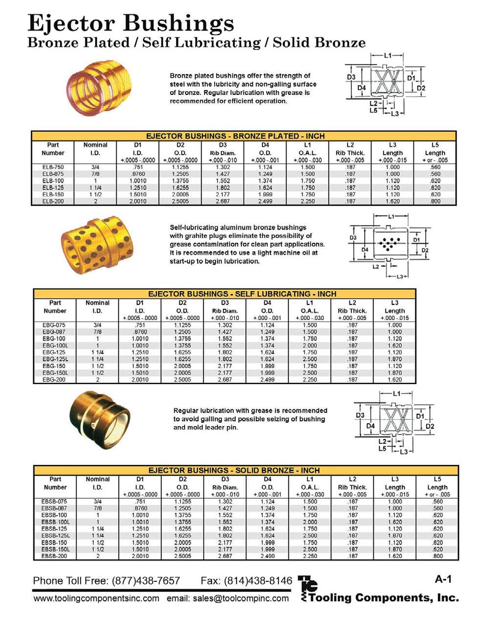
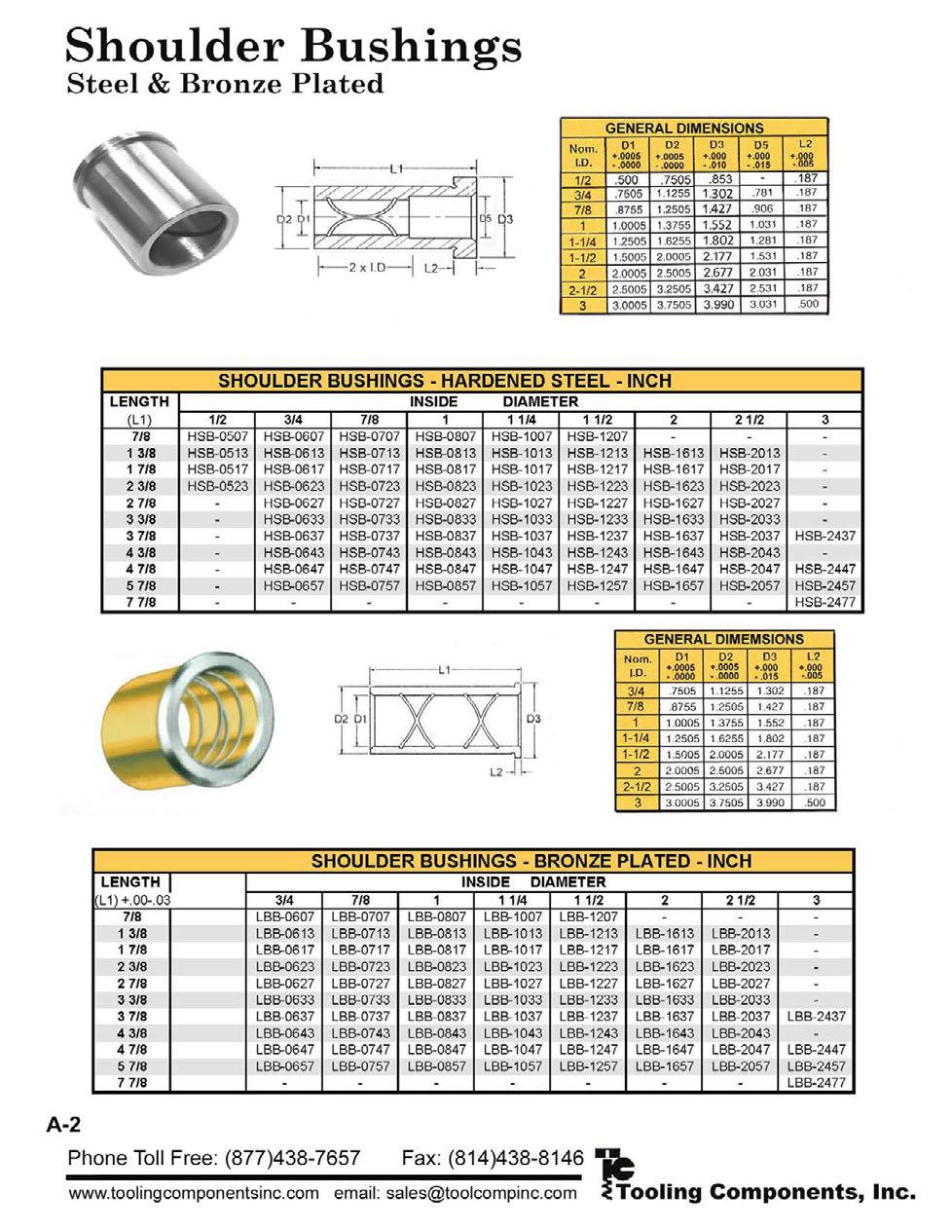
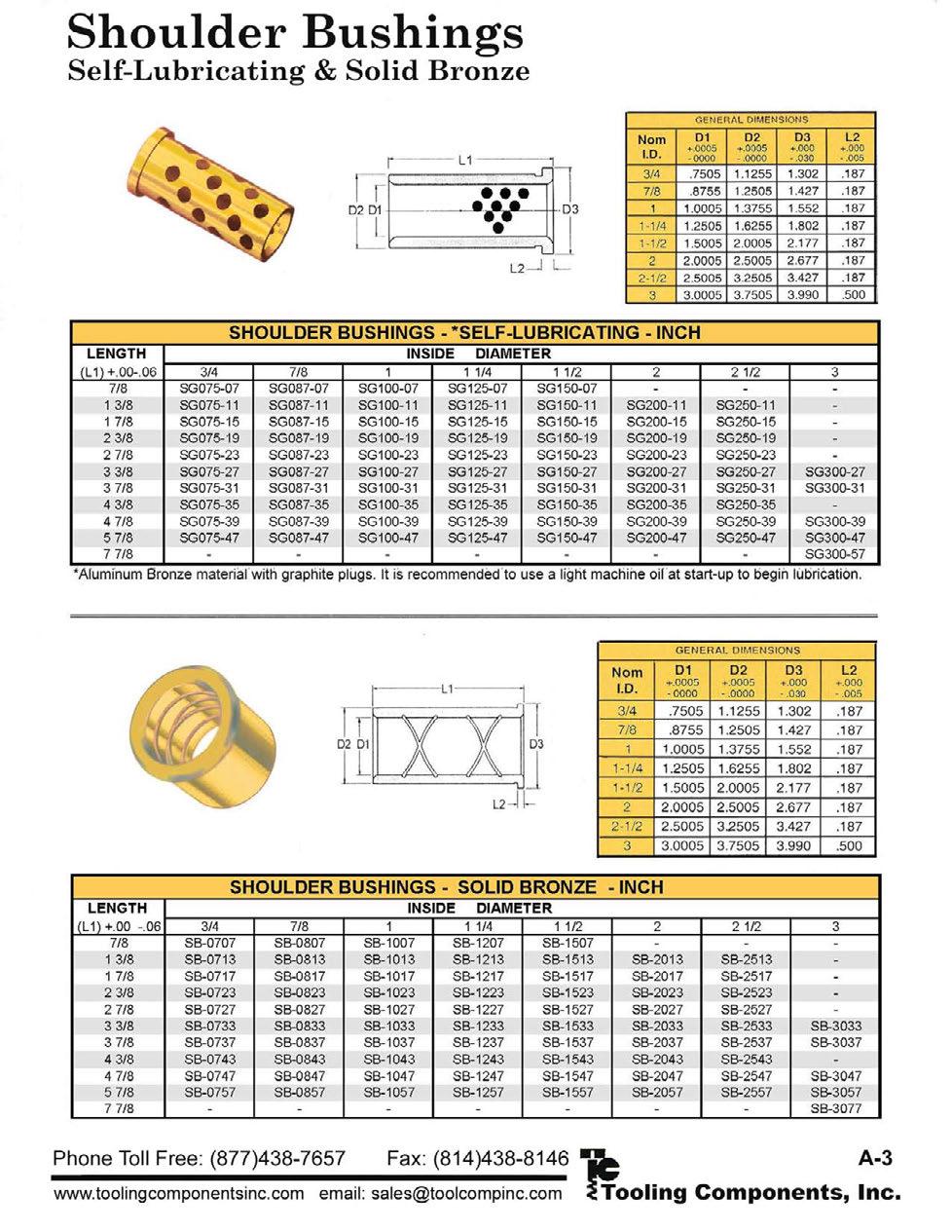
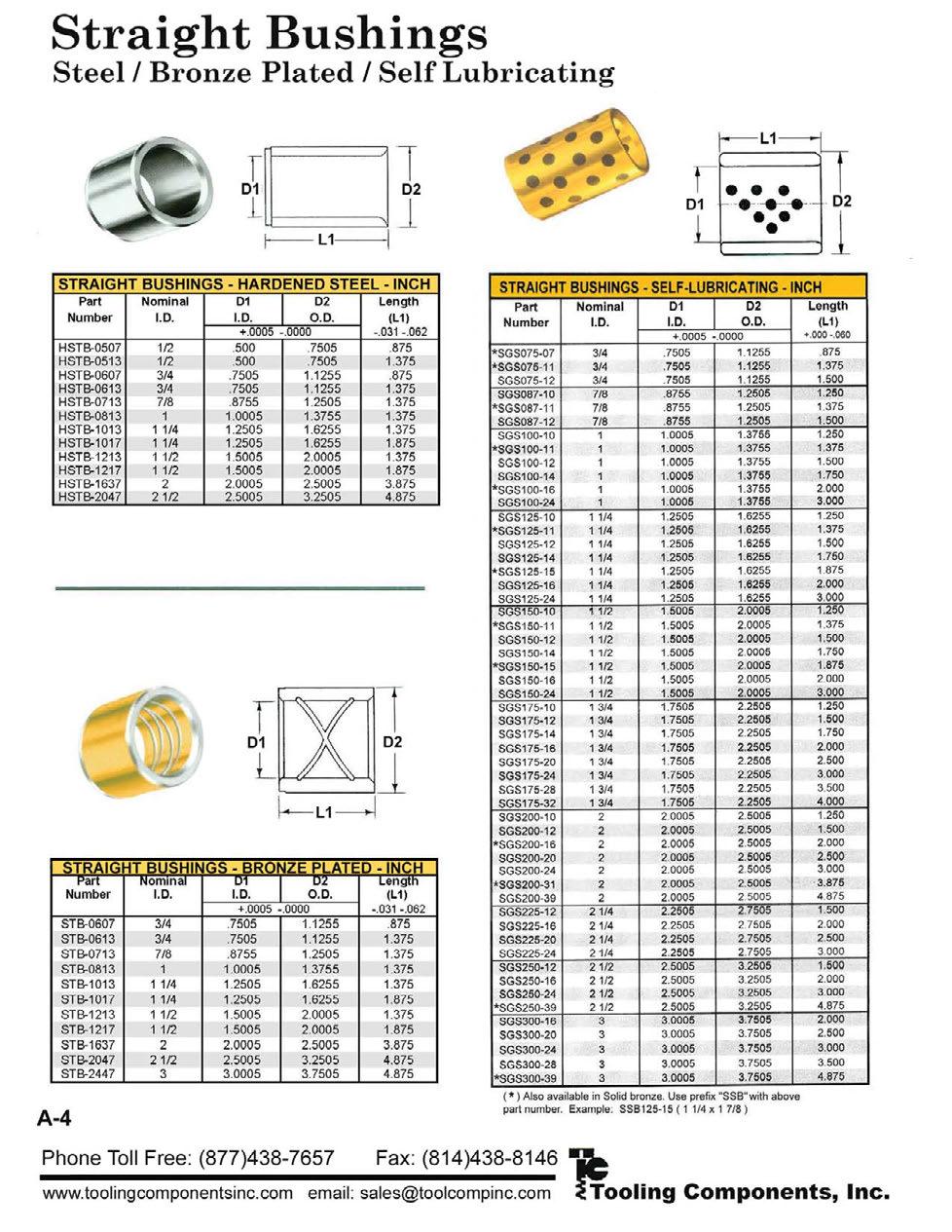
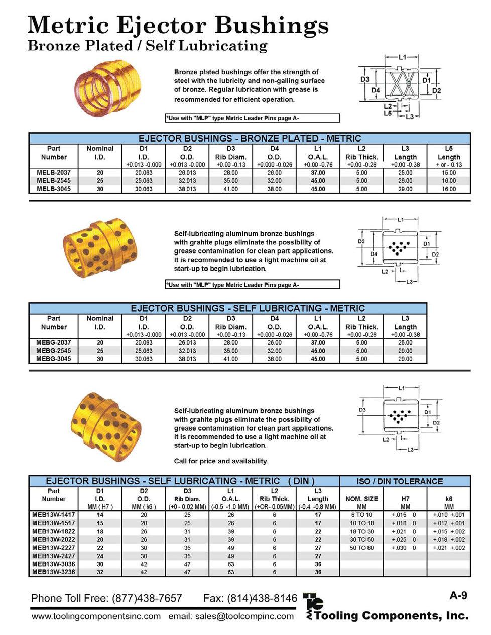
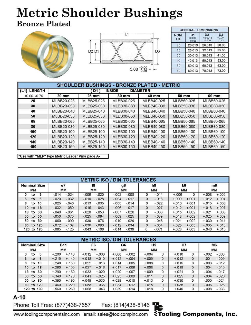
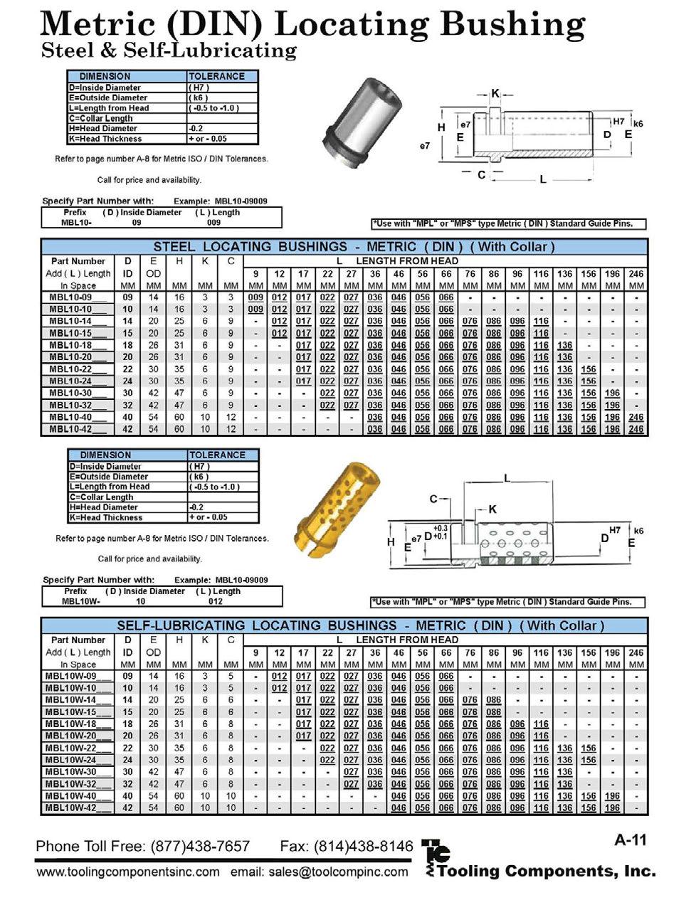
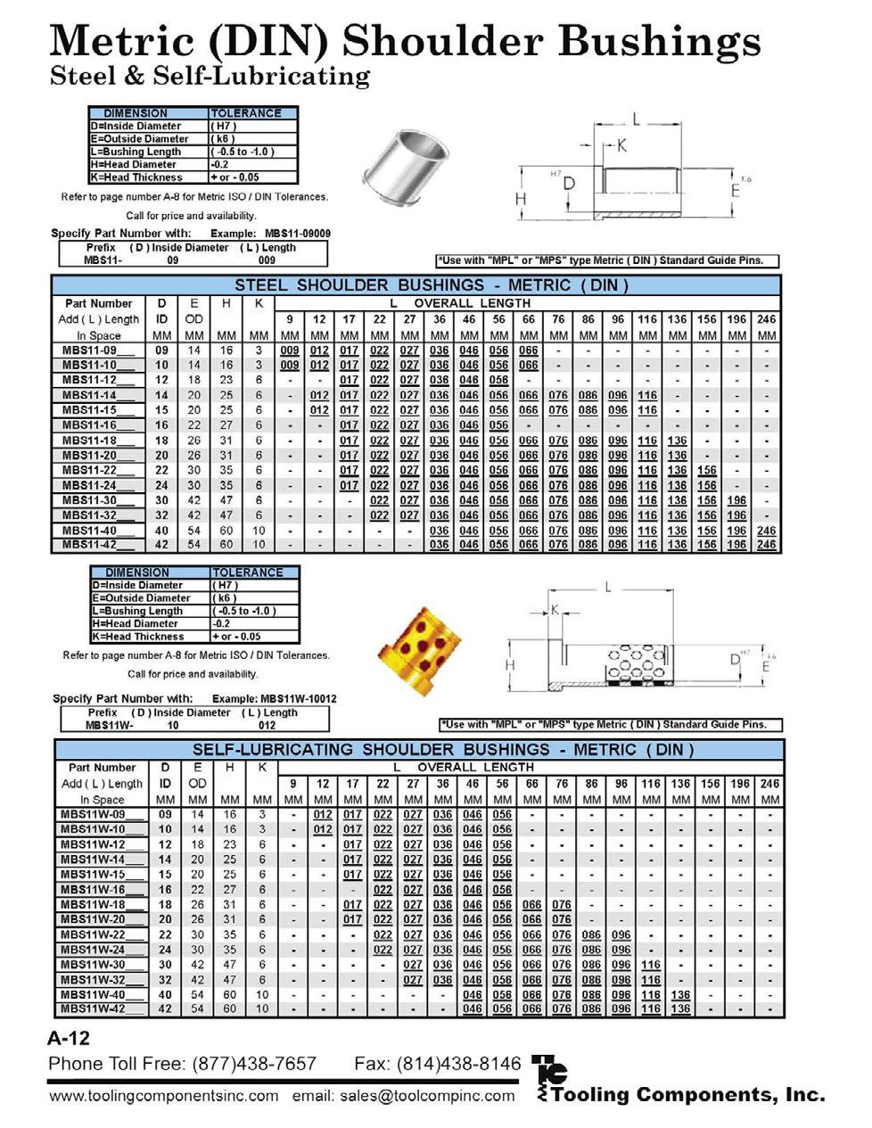
22 BUSHINGS General Information Bushings... 2 & 3 STANDARD SHOULDER BUSHINGS Bronze Plated & Solid Steel... 4 Solid Bronze & Self-Lubricating... 5 Pressed Fit... 6 Bushings for Lifter Pin Metric... 6 Long & Extra Long Shoulder Bushings... 7 SHORT SHOULDER BUSHINGS Bronze Plated... 8 Solid Bronze... 9 Self-Lubricating METRIC BUSHINGS NAAMS & 12 Standard Shoulder Bushings Metric Long & Extra Long Shoulder Bushings Metric Short Shoulder Bushings Metric TECHNICAL INFORMATION Toe Clamp Selection Toe Clamp Placement Bore Sizes for Pins & Bushings GUIDE PINS, continued Guide Pins Tap Fit (Demountable) & 29 Guide Pins Shoulder Inch Metric Guide Pins Removable Stripper Guide Pins & Bushings & 35 STOCK LIFTERS 75 Stock Lifters Stock Lifters Rail Lifters Rail Lifters Mini Lifters Repair Parts Metric Lifter Pins Stop Blocks PAD RETAINERS Pad Retainers, Standard Inch Pad Retainers, Reverse Mount Inch Pad Retainers, Standard & Reverse Metric.. 46 Spool Type Pad Retainers Metric MISCELLANEOUS BUSHINGS Running Fit Bushings Hardened Running Fit Bushings Soft Guide Bar Bushings (Wiper Bushings) Precision Bearings GUIDE PINS General Information Pins Straight Guide Pins TN & ATN Straight Guide Pins TPB Straight Guide Pins TPC Straight Guide Pins NAAMS Straight Guide Pins Hollow Straight Guide Pins TN Metric Straight Guide Pins TPB Metric Short SC-GSC SCB-GSCB SHOULDER BUSHING STYLES Standard AC-GAC ACB-GACB Long LAC-GLAC Extra-Long XLAC-GXLAC All bronze plated shoulder bushings must be wring-fit in the die shoe. It is also recommended that Solid Bronze shoulder bushings be mounted similarly. Bronze plated bushings feature fi gure 8 oil grooves for maximum lubrication. For long wear, bronze plated bushings should be lubricated with a high temperature, high pressure lithium grease on a regular basis. Self-lubricating bronze with graphite bushings require initial lubrication with light oil. Periodic lubrication will extend the life of self-lubricating bushings. Do not use grease. 2

23 Specials have become very important at Lamina. The table below will give a basic idea of our everyday manufacturing capabilities. If you have a need for special bushings, please send your requests for quotations. See page 22 for pin manufacturing capabilities. BUSHING MANUFACTURING CAPABILITIES Straight & Shoulder Bronze Plated & Solid Steel Solid Bronze Self- Lubricating Series Inch Min. Length Max. Length Series Metric Min. Length Max. Length We are not restricted to the above parameters. Every quote will be analyzed for manufacturing possibility. LAMINA DIE SET STANDARD GRIND (LDSS) Tapers.0005 Nominal Wring Fit Diameter Slight taper on wring fit diameter facilitates installation. (This feature is standard on all bronze plated and solid steel shoulder bushings unless otherwise noted.) Bushings are held in place with toe clamps and screws unless otherwise noted. In the following pages bronze plated and solid steel bushings which are listed as ground are LDSS ground. GUIDE BUSHINGS Class 1 & 2 bushing dimensions shown opposite are for use in precision die sets. Class 3 bushings are for use with automotive, hardware, forming or draw dies where stamping stock is thicker than 1/16, and clearances between punch and die sections will be more than.003 per side. Bronze-Plated Bushings Available in Class 1 or Class 2 Solid Bronze Bushings Available in Class 1 or Class 2 Hardened Steel Bushings available in Class 2 Self-Lubricating Bushings available in Class 3 NOMINAL PIN DIAMETER 3/4 7/ /4 1-1/2 1-3/ /2 3 LAMINA BUSHINGS I.D. Dimensions Class 1 Class 2 Class /4 4-1/
24 Bushings Inch Wring Fit Style D4 D2 L3.187 BRONZE PLATED SOLID STEEL *See page 3 for details. See pages 16 & 17 for toe clamp installation instructions. C L Grease Fitting (incl.) Grease Fittings Ø3/4-1/4-28 NTF, 5/16 hex Ø7/ /8-27 NPTF, 7/16 hex.75 D5 D3 L4.188 D-Clamps & Screws are included with wring fi t style bushings. STANDARD SHOULDER BUSHINGS BRONZE PLATED D2 D3 D4 D5 L3 L4 NOM WRING FIT Class 2* Class 1* HEAD SHOULDER HEAD OVERALL WRING HEAD DIAMETER PIN OD OD OD FIT GROUND UNGROUND GROUND UNGROUND DIA GROUND UNGROUND GROOVE GAC-750-S AC-750-S GAC7501S AC7501S 3/ GAC-875-S AC-875-S GAC8751S AC8751S 7/ GAC-100-S AC-100-S GAC1001S AC1001S GAC-100-L AC-100-L GAC1001L AC1001L GAC-125-S AC-125-S GAC1251S AC1251S / GAC-125-L AC-125-L GAC1251L AC1251S GAC-150-SP GAC-150-S AC-150-S GAC1501S AC1501S 1-1/ GAC-150-L AC-150-L GAC1501L AC1501L GAC-175-SP GAC-175-S AC-175-S GAC1751S AC1751S 1-3/ GAC-175-L AC-175-L GAC1751L AC1751L GAC-200-SP GAC-200-S AC-200-S GAC2001S AC2001S GAC-200-L AC-200-L GAC2001L AC2001L GAC-250-S AC-250-S GAC2501S AC2501S 2-1/ GAC-300-S AC-300-S GAC3001S AC3001S STANDARD SHOULDER BUSHINGS SOLID STEEL D2 D3 D4 D5 L3 L4 Class 2 only* NOMINAL WRING FITDIAMETER HEAD WRING HEAD SHOULDER OVERALL HEAD PIN OD FIT GROUND UNGROUND OD OD DIAMETER GROUND UNGROUND GROOVE GAC-750-SS AC-750-SS 3/ GAC-100-SS AC-100-SS GAC-100-SS2 AC-100-SS GAC-125-SS AC-125-SS / GAC-125-SS2 AC-125-SS GAC-150-SS AC-150-SS / GAC-150-SS2 AC-150-SS GAC-175-SS AC-175-SS / GAC-175-SS2 AC-175-SS GAC-200-SS AC-200-SS GAC-200-SS2 AC-200-SS GAC-250-SS AC-250-SS 2-1/
 Grease Fittings Ø3/4-1/4-28 NTF, 5/16 hex Ø7/8-1/8-27 NPTF, 7/16 hex D5 D3 D-Clamps & Screws are included with wring fi t style bushings.")

25 Bushings Inch Wring Fit Style D4 D2 L L4.188 SOLID BRONZE SELF-LUBRICATING *See page 3 for details. See pages 16 & 17 for toe clamp installation instructions. Grease Fitting (Solid Bronze only) Grease Fittings Ø3/4-1/4-28 NTF, 5/16 hex Ø7/8-1/8-27 NPTF, 7/16 hex D5 D3 D-Clamps & Screws are included with wring fi t style bushings. STANDARD SHOULDER BUSHINGS SOLID BRONZE D2 NOM WRING FIT D3 D4 D5 L3 L4 Class 2* Class 1* SHOUL- HEAD OVER- WRING PIN DIAMETER HEAD HEAD DER OD ALL FIT OD GROUND UNGROUND GROUND UNGROUND DIA GROUND UNGROUND OD GROOVE GAC-750-SB AC-750-SB GAC7501SB AC7501SB 3/ GAC-875-SB AC-875-SB GAC8751SB AC8751SB 7/ GAC-100-SB AC-100-SB GAC1001SB AC1001SB GAC-125-SB AC-125-SB GAC1251SB AC1251SB 1-1/ GAC-150-SB AC-150-SB GAC1501SB AC1501SB 1-1/ GAC-175-SB AC-175-SB GAC1751SB AC1751SB 1-3/ GAC-200-SB AC-200-SB GAC2001SB AC2001SB GAC-250-SB AC-250-SB GAC2501SB AC2501SB 2-1/ GAC-300-SB AC-300-SB GAC3001SB AC3001SB Class 3 only* STANDARD SHOULDER BUSHINGS SELF LUBRICATING NOMINAL PIN DIAMETER D2 WRING FIT DIAMETER Note: Self-lubricating bronze with graphite bushings require initial lubrication with light oil. Periodic lubrication will extend the life of self-lubricating bushings. Do not use grease. D3 HEAD OD D4 SHOULDER OD D5 HEAD OD GROOVE OVERALL L3 WRING FIT L4 HEAD GROUND UNGROUND GROUND UNGROUND GACB750S ACB750S 3/ GACB100S ACB100S GACB125S ACB125S 1-1/ GACB150S ACB150S 1-1/ GACB175S ACB175S 1-3/ GACB200S ACB200S GACB250S ACB250S 2-1/ GACB300S ACB300S All Standard Shoulder Bushings (unless otherwise noted) are to be wring fit and held in place with toe clamps and screws. This means that the bushing should be installed into the die shoe using a wringing (circular) motion with the heel of the hand. Please see bore size information on page 18. 5


26 Bushings Inch Pressed Fit Style Press Fit Shoulder Bushings allow for fast, easy installation. Eliminates the use of clamps and screws. D2 L3 Grease Fittings 3/4-1/4-28 NTF, 5/16 hex 7/8-1/8-27 NPTF, 7/16 hex.750 L4 BRONZE PLATED Figure 8 oil grooves allow the lubricant to fl ow smoothly throughout the bushing I.D. Grease Fitting D3 NOMINAL PIN DIAMETER / /2 SHOULDER BUSHING PRESS FIT * D2 PRESS FIT DIAMETER D3 HEAD O.D. OVERALL L4 HEAD L3 PRESS FIT Recommended Bore Size *Please note! Press Fit bushings have tapered holes, larger at press fit end. This facilitates honing, since the bore will close up in a more nearly straight line when pressed in. While these bushings are precision fi nished on the O.D. a small amount of stock is left on the I.D. to allow for honing because they are pressed fi t type. Toe clamps and screws are not provided with press fi t shoulder bushings and they do not come with an LDSS grind. BUSHINGS FOR LIFTER PINS METRIC D2 D2 MBL MBL MBL


27 Bushings Wring Fit Style D4 D2 L BRONZE PLATED SOLID STEEL *See page 3 for details. See pages 16 & 17 for toe clamp placement instructions. D-Clamps & Screws are included with wring fi t style bushings. Grease Fittings Ø3/4-1/4-28 NTF, 5/16 hex Ø7/8-1/8-27 NPTF, 7/16 hex.75 L4 D5 D3 Grease Fitting Class 2* Class 1* LONG SHOULDER BUSHINGS BRONZE PLATED NOM PIN DIA D2 WRING FIT DIAMETER D3 HEAD OD D4 SHOUL- DER OD D5 HEAD OD GROOVE OVER- ALL L3 WRING FIT L4 HEAD GROUND UNGROUND GROUND UNGROUND GROUND UNGROUND GLAC-750-S LAC-750-S GLAC7501S LAC7501S 3/ GLAC-875-S LAC-875-S GLAC8751S LAC8751S 7/ GLAC-100-S LAC-100-S GLAC1001S LAC1001S GLAC-125-S LAC-125-S GLAC1251S LAC1251S 1-1/ GLAC-150-S LAC-150-S GLAC1501S LAC1501S 1-1/ GLAC-150-SP 1-1/ GLAC-175-S LAC-175-S GLAC1751S LAC1751S 1-3/ GLAC-200-S LAC-200-S GLAC2001S LAC2001S GLAC-250-S LAC-250-S GLAC2501S LAC2501S 2-1/ GLAC-300-S LAC-300-S GLAC3001S LAC3001S EXTRA-LONG SHOULDER BUSHINGS BRONZE PLATED Class 2* Class 1* NOM PIN DIA D2 WRING FIT DIAMETER D3 HEAD OD D4 SHOUL- DER OD D5 HEAD OD GROOVE OVER- ALL L3 WRING FIT L4 HEAD GROUND UNGROUND GROUND UNGROUND GROUND UNGROUND GXLAC-750-S XLAC-750-S GXLAC7501S XLAC7501S 3/ GXLAC-875-S XLAC-875-S GXLAC8751S XLAC8751S 7/ GXLAC-100-S XLAC-100-S GXLAC1001S XLAC1001S GXLAC-125-S XLAC-125-S GXLAC1251S XLAC1251S 1-1/ GXLAC-150-S XLAC-150-S GXLAC1501S XLAC1501S 1-1/ LONG & EXTRA LONG SHOULDER BUSHINGS SOLID STEEL D2 D3 D4 D5 L3 L4 Class 2 only* NOMINAL WRING FIT DIAMETER HEAD HEAD SHOULDER OVERALL WRING FIT HEAD PIN OD GROUND UNGROUND OD OD DIAMETER GROUND UNGROUND GROOVE GXLAC-750-SS XLAC-750-SS 3/ GXLAC-100-SS XLAC-100-SS GXLAC-125-SS XLAC-125-SS 1-1/ GXLAC-150-SS XLAC-150-SS 1-1/ GXLAC-175-SS XLAC-175-SS 1-3/ GLAC-200-SS LAC-200-SS GXLAC-200-SS XLAC-200-SS GLAC-250-SS LAC-250-SS 2-1/


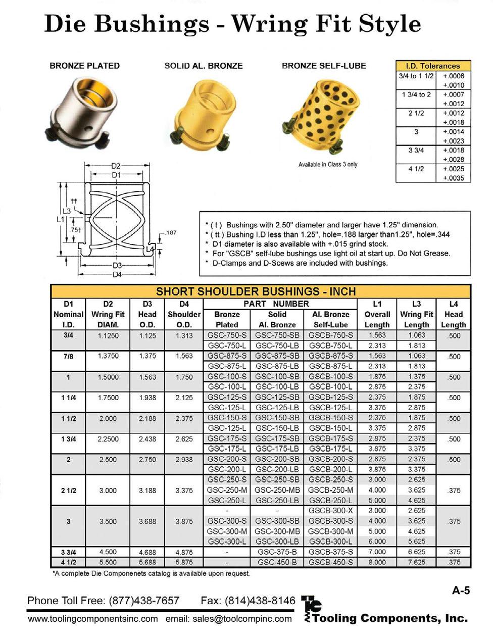
28 Bushings Inch Wring Fit Style D2 Grease Fittings Ø3/4-1/4-28 NTF, 5/16 hex Ø7/8-1/8-27 NPTF, 7/16 hex L BRONZE PLATED *See page 3 for details. See pages 16 & 17 for toe clamp placement instructions. D-Clamps & Screws are included with wring fi t style bushings. SHORT SHOULDER BUSHINGS BRONZE PLATED D2 D3 D4 L3 NOM Class 2* Class 1* WRING FIT DIAMETER SHOUL- OVER- WRING HEAD PIN DER ALL FIT UNGROUND GROUND GROUND UNGROUND OD DIA GROUND UNGROUND OD SC-750-S GSC-750-S GSC7501S SC7501S / SC-750-L GSC-750-L GSC7501L SC7501L SC-875-S GSC-875-S GSC8751S SC8751S / SC-875-L GSC-875-L GSC8751L SC8751L SC-100-S GSC-100-S GSC1001S SC1001S SC-100-L GSC-100-L GSC1001L SC1001L SC-125-S GSC-125-S GSC1251S SC1251S / SC-125-L GSC-125-L GSC1251L SC1251L SC-150-S GSC-150-S GSC1501S SC1501S / SC-150-L GSC-150-L GSC1501L SC1501L SC-175-S GSC-175-S GSC1751S SC1751S / SC-175-L GSC-175-L GSC1751L SC1751L SC-200-S GSC-200-S GSC2001S SC2001S SC-200-L GSC-200-L GSC2001L SC2001L SC-250-S GSC-250-S GSC2501S SC2501S SC-250-M GSC-250-M GSC2501M SC2501M 2-1/ SC-250-L GSC-250-L GSC2501L SC2501L SC-300-S GSC-300-S GSC3001S SC3001S SC-300-M GSC-300-M GSC3001M SC3001M SC-300-L GSC-300-L GSC3001L SC3001L Reference on page 9. For bushing I.D.s less than 1.25, hole diameter is.188; for bushing I.D.s 1.25+, hole diameter is.344. D3 D4 L4 HEAD L4 Lamina pins and bushings are used in die sets for the metal stamping industry. 8

29 Bushings Inch Wring Fit Style D2 Grease Fittings Ø3/4-1/4-28 NTF, 5/16 hex Ø7/8-1/8-27 NPTF, 7/16 hex L *See page 3 for details. SOLID BRONZE See pages 16 & 17 for toe clamp placement instructions. D-Clamps & Screws are included with wring fi t style bushings. L4 D3 D4 SHORT SHOULDER BUSHINGS SOLID BRONZE D2 D3 D4 L3 L4 NOM WRING FIT HEAD SHOUL- OVER- WRING HEAD Class 2* Class 1* PIN DIAMETER OD DER ALL FIT GROUND UNGROUND GROUND UNGROUND DIA GROUND UNGROUND OD GSC-750-SB SC-750-SB GSC7501SB SC7501SB / GSC-750-LB SC-750-LB GSC7501LB SC7501LB GSC-875-SB SC-875-SB GSC8751SB SC8751SB / GSC-875-LB SC-875-LB GSC8751LB SC8751LB GSC-100-SB SC-100-SB GSC1001SB SC1001SB GSC-100-LB SC-100-LB GSC1001LB SC1001LB GSC-125-SB SC-125-SB GSC1251SB SC1251SB / GSC-125-LB SC-125-LB GSC1251LB SC1251LB GSC-150-SB SC-150-SB GSC1501SB SC1501SB / GSC-150-LB SC-150-LB GSC1501LB SC1501LB GSC-175-SB SC-175-SB GSC1751SB SC1751SB / GSC-175-LB SC-175-LB GSC1751LB SC1751LB GSC-200-SB SC-200-SB GSC2001SB SC2001SB GSC-200-LB SC-200-LB GSC2001LB SC2001LB GSC-250-SB SC-250-SB GSC2501SB SC2501SB GSC-250-MB SC-250-MB GSC2501MB SC2501MB 2-1/ GSC-250-LB SC-250-LB GSC2501LB SC2501LB GSC-300-SB SC-300-SB GSC3001SB SC3001SB GSC-300-MB SC-300-MB GSC3001MB SC3001MB GSC-300-LB SC-300-LB GSC3001LB SC3001LB GSC-375-B SC-375-B 3-3/ GSC-450-B SC-450-B 4-1/ Bushings of 2.50 diameter and larger have 1.25 dimensions. For bushing I.D.s less than 1.25, hole diameter is.188; for bushing I.D.s 1.25+, hole diameter is.344. All Short Shoulder Bushings (unless otherwise noted) are to be wring fit and held in place with toe clamps & screws. This means the bushing should be installed into the die shoe using a wringing (circular) motion with the heel of the hand. Please see bore size information on page 18. 9


30 Bushings Inch Wring Fit Style D2.187 L3 BRONZE with SELF-LUBRICAT- ING GRAPHITE PLUGS *See page 3 for details. See pages 16 & 17 for toe clamp placement instructions. Class 3 only* SHORT SHOULDER BUSHINGS SELF-LUBRICATING NOM PIN DIA D-Clamps & Screws are included with wring fi t style bushings. D2 WRING FIT DIAMETER GROUND UNGROUND GROUND UNGROUND D3 HEAD OD D4 SHOULDER OD OVERALL L3 WRING FIT L4 HEAD GSCB750S SCB750S / GSCB750L SCB750L GSCB875S SCB875S / GSCB875L SCB875L GSCB100S SCB100S GSCB100L SCB100L GSCB125S SCB125S / GSCB125L SCB125L GSCB150S SCB150S / GSCB150L SCB150L GSCB175S SCB175S / GSCB175L SCB175L GSCB200S SCB200S GSCB200L SCB200L GSCB250S SCB250S GSCB250M SCB250M 2-1/ GSCB250L SCB250L GSCB300X SCB300X GSCB300S SCB300S GSCB300M SCB300M GSCB300L SCB300L GSCB375S SCB375S 3-3/ GSCB450S SCB450S 4-1/ D3 D4 L4 Self-lubricating bronze with graphite bushings require initial lubrication with light oil. Periodic lubrication will extend the life of self-lubricating bushings. Do not use grease. 10


31 Bushings Metric Wring Fit Style D2 BRONZE with SELF-LUBRICATING GRAPHITE PLUGS See page 17 for toe clamp placement instructions. SHORT-SHOULDER BUSHINGS SELF-LUBRICATING - NAAMS NOMINAL PIN DIAMETER G G G G G G G G G TOL H D2 WRING FIT DIAMETER G720000C Clamps & Screws are included with NAAMS wring fi t style bushings. D2 Tol g D3 D4 D3 D4 OVERALL 6 L3 WRING FIT L3 No. TOE CLAMPS & SCREWS 3 NOTE: Evenly distributed graphite covers 20-30% of the sliding surface. Graphite is positioned to ensure overlapping in the slide direction. See page 17 for Toe Clamp information and 18 for bore sizes. These short shoulder bushings are made especially for automotive stamping companies. They conform to the standards agreed to by the North American Automotive Metric Standards group. AUTOMOTIVE METRIC NAAMS STANDARD 11


32 Bushings Metric These pad bushings are made especially for automotive stamping companies. They conform to the standards agreed to by the North American Automotive Metric Standards group. D2 BRONZE with SELF LUBRICATING GRAPHITE PLUGS D4 6 See page 17 for toe clamp installation instructions. NOMINAL PIN DIAMETER G G G G G G G G SELF-LUBRICATING PAD BUSHINGS - NAAMS TOL c D2 WRING FIT DIAMETER D2 TOL g D4 OVERALL NOTE: Evenly distributed graphite covers 20-30% of the sliding surface. Graphite is positioned to ensure overlapping in the slide direction. AUTOMOTIVE METRIC NAAMS STANDARD See page 18 for bore size information. A full complement of flat products is also available from the Lamina Components line. 12
 (UNGROUND) D-Clamps & Screws are included with wring fi t style bushings.")
33 Bushings Metric Wring Fit Style Bronze plated shoulder bushings are available in metric sizes. D4 D2 L3 5 5 BRONZE PLATED See pages 16 & 17 for toe clamp installation instructions. (GROUND) (UNGROUND) D-Clamps & Screws are included with wring fi t style bushings. Grease Fitting All Standard Shoulder Bushings (unless otherwise noted) are to be wring fit and held in place with toe clamps and screws. This means the bushing should be installed into the die shoe using a wringing (circular) motion with the heel of the hand. Please see clamping information on page 16 & 17 and bore size information on page Grease Fittings, North America Ø18 & 19mm - 1/4-28 NTF, 5/16 hex Ø24-80mm - 1/8-27 NPTF, 7/16 hex D5 D3 STANDARD SHOULDER BUSHINGS BRONZE PLATED METRIC NOM PIN DIA GAC-18S AC-18S GAC-19S AC-19S GAC-24S AC-24S GAC-25S AC-25S GAC-30S AC-30S GAC-32S AC-32S GAC-40S AC-40S GAC-42S AC-42S GAC-50S AC-50S GAC-52S AC-52S GAC-63S AC-63S GAC-80S AC-80S *Unground wring fi t tolerance is D2 WRING FIT DIAMETER (GROUND) (UNGROUND) D3 HEAD O.D. D4 SHOULDER O.D D5 HEAD OD GROOVE OVERALL L3 WRING FIT L4 HEAD L4 NO. CLAMPS & SCREWS

34 Bushings Metric Wring Fit Style D4 D2 L D-Clamps & Screws are included with wring fi t style bushings. L4 See pages 16 & 17 for toe clamp placement instructions. *Unground wring fi t tolerance is Grease Fittings, North America Ø18 & 19mm - 1/4-28 NTF, 5/16 hex Ø24-80mm - 1/8-27 NPTF, 7/16 hex D5 D3 Grease Fitting LONG & EXTRA LONG SHOULDER BUSHINGS BRONZE PLATED METRIC D2 NOM WRING FIT O.D. PIN GROUND UNGROUND DIA GROUND UNGROUND GLAM-18F GLAC-18S GLAM-19F GLAC-19S GLAM-24F GLAC-24S GLAM-25F GLAC-25S GLAM-30F GLAC-30S GLAM-32F GLAC-32S GLAM-40F GLAC-40S GLAM-42F GLAC-42S GLAM-50F GLAC-50S GLAM-52F GLAC-52S GLAM-63F GLAC-63S GLAM-80F GLAC-80S LAM-18F LAC-18S LAM-19F LAC-19S LAM-24F LAC-24S LAM-25F LAC-25S LAM-30F LAC-30S LAM-32F LAC-32S LAM-40F LAC-40S LAM-42F LAC-42S LAM-50F LAC-50S LAM-52F LAC-52S LAM-63F LAC-63S LAM-80F LAC-80S D3 HEAD O.D. D4 SHOULDER O.D D5 HEAD OD GROOVE OVERALL L3 WRING-FIT L4 HEAD NO. CLAMPS & SCREWS All Standard Shoulder Bushings (unless otherwise noted) are to be wring fit and held in place with toe clamps and screws. This means that the bushing should be installed into the die shoe using a wringing (circular) motion with the heel of the hand. Please see clamping information on page 16 & 17 and bore size information on page


35 Bushings Metric Wring Fit Style D2 Grease Fittings, North America Ø18 & 19mm - 1/4-28 NTF, 5/16 hex Ø24-80mm - 1/8-27 NPTF, 7/16 hex See pages 16 & 17 for toe clamp placement instructions. * L3 H1 SHORT SHOULDER BUSHINGS BRONZE PLATED METRIC *Ø4.76 for bushings with nom. I.D.s between 18 & 32mm. *Ø8.73 for bushings with nom. I.D.s between 40 & 80mm. D-Clamps & Screws are included with wring fi t style bushings. D2 D4 L3 H1 NOM WRING FIT DIAMETER D3 SHOULDER OVERALL WRING NO. HEAD OD FIT LUBE CLAMPS & PIN O.D HOLE DIA SCREWS GROUND UNGROUND GROUND *UNGROUND 0.26 CENTER GSC-18S SC-18S GSCL-18F SCL-18F GSC-19S SC-19S GSCL-19F SCL-19F GSC-24S SC-24S GSCL-24F SCL-24F GSC-25S SC-25S GSCL-25F SCL-25F GSC-30S SC-30S GSCL-30F SCL-30F GSC-32S SC-32S GSCL-32F SCL-32F GSC-40S SC-40S GSCL-40F SCL-40F GSC-42S SC-42S GSCL-42F SCL-42F GSC-50S SC-50S GSCL-50F SCL-50F GSC-52S SC-52S GSCL-52F SCL-52F GSC-63S SC-63S GSCL-63F SCL-63F GSC-80S SC-80S *Unground wring fi t tolerance is D3 D4 5 All Standard Shoulder Bushings (unless otherwise noted) are to be wring fit and held in place with toe clamps and screws. This means that the bushing should be installed into the die shoe using a wringing (circular) motion with the heel of the hand. Please see clamping information on page 16 & 17 and bore size information on page


36 Toe Clamp Information for Inch & Metric Plain Bearing Die Bushings Bushing ID # Provided AC, LAC, XLAC D-Clamps SC CLAMP & SCREW PLACEMENT INCH Bolt Circle Diameter X-40 Clamps LMB AC, LAC, XLAC SC Bushing ID AC,LAM, LAC, SC METRIC Bolt Circle Diameter # Provided D-Clamps X-40 Clamps LMB Toe Clamp Dimensions D-Clamp & BHC Screw (5/16-18 x 3/4 ) D-Clamp & F Metric Screw (M8 x mm) X-40-Clamp & SHC Screw (5/16-18 x 3/4 ) X-40-Clamp & F Metric Screw (M8 x mm) REPLACEMENT KITS CLAMPS & SCREWS D-Clamps Nom Pin # Clamps No. of & Screws Kits Diameters per Kit Needed Nom Pin # Clamps No. of & Screws Kits Diameters per Kit Needed CSK /8-7/8 2 1 CSK CSK /4 3 1 CSK CSK /2 2 2 CSK CSK /2 3 2 X40-Clamps CSK /8-7/8 2 1 CSK CSK /4 3 1 CSK CSK /2 2 2 CSK CSK /2 3 2 Bolt Circle Diameter Drawing above can refer to either D-Clamps or X-40-Clamps 16


37 Toe Clamp Information for Inch & Metric Demountable Components NOM. PIN DIA. 1, 1 1 /4, & 1 1 /2 1 3 /4, 2, 2 1 /2 & /4, 2, 2 1 /2 & /4, 2, 2 1 /2 & 3 BALL-BEARING DEMOUNTABLE COMPONENT CLAMP ARRANGEMENTS STANDARD LEFT - RIGHT FEED FEED FEED FEED FRONT to BACK FEED (Center Post Die Sets) FEED FEED FEED FEED ROUND DIES BOLT CIRCLE DIAMETERS DEMOUNTABLE BALL BEARING BUSHINGS Nominal Bolt Circle Bushing Diameter Diameter / / / / DEMOUNTABLE BALL BEARING & PLAIN BEARING PINS Nominal Pin Bolt Circle Diameter Diameter / / / / KEYLESS DEMOUNTABLE BALL BEARING BUSHINGS Nominal Bolt Circle Bushing Diameter Diameter / / / / KEYLESS DEMOUNTABLE BALL BEARING PINS Nominal Pin Bolt Circle Diameter Diameter / / / / BUSHING CLAMPING PROCEDURES AUTOMOTIVE METRIC NAAMS STANDARD 6 Clamp Part No: G720000C M8 x 1.25 x 20 Long D4 (O.D. of Bushing Shoulder) B.C. = D (ID of Bushing) M8 x 1.25 Tap (3) Holes equally spaced D4 B.C. (D4 + 18) NOTES & SPECIFICATION: Bushings will be supplied with (3) toe clamps and (3) screws - M8. Screws must engage 16mm minimum deep into die shoe. 17
38 18 Nom. Pin Diameter 3/4 7/ /4 1-1/2 1-3/ /2 3 GSC Only 3 3-3/4 4-1/2 18mm 19mm 24mm 25mm 30mm 32mm 40mm 42mm 50mm 52mm 63mm 80mm 100mm 115mm 125mm Standard Inch GAC GLAC GXLAC & GSC Style Bushings RECOMMENDED BORE SIZES for PLAIN BEARING PINS & BUSHINGS Standard Metric GAC,GLAC, GLAM & GSC Style Bushings Short Shoulder & Pad Bushings NAAMS DEFINITIONS OF MOUNTING PROCEDURES Pins and bushings require specific mounting procedures. By following these procedures the components should give maximum life and reduce downtime due to improper alignment, breakage and uneven wear. Pressed Fit The component is installed in an interference condition: the bore size is smaller than the pressed fi t portion of the component. Bushing Liner For Removable Pin Straight Guide Pins Inch TN & ATN Straight Guide Pins Metric TN Straight Guide Pins Inch TPC Bushings that require a pressed fi t should never be frozen or hammered. They should be forced into place using a hydraulic press or other proper tooling. Improper methods can permanently change the tolerance of the component. Pins can be forced into place using a hydraulic press; or the pins can be frozen and pressed into place. Lamina does not recommend hammering pins into place. Hammering can cause the pins to mushroom or expand on the pin Demountable Inch Guide Pins Standard Metric Guide Pins Wring Fit Wring Fit Wring Fit Pressed Fit Pressed Fit Pressed Fit Pressed Fit Pressed Fit Tap Fit Tap Fit Tap Fit Straight Guide Pins NAAMS Guide Pins with Shoulders NAAMS end resulting in permanent distortion of the component. Tap Fit The component should be tapped using a soft hammer into the bored hole and secured with toe clamps. Wring Fit The component should be installed using a wringing (circular) motion with the heel of the hand. Wring fit components are to be held in place with toe clamps, retaining rings or plates.

39 Bearings Pressed Fit Chamfer Figure 8 Oil Groove Sharp Corner (Both Ends) For Machine Tools, Fixtures, etc. Straight Design, Wiper type Lamina-Bronze on steel provides longer wearing running fits No reaming or honing after press fitting bearing. HEAT TREATED L2 I.D D2 O.D D2 BEARINGS RUNNING FIT HARDENED RECOM- MENDED BORE SIZE L Bearings for Radial or Linear Applications I.D D2 O.D *.0000 RECOM- MENDED BORE SIZE L 625-x-75-RFB x-175-RFB x-100-RFB x-200-RFB x-125-RFB x-250-RFB x-75-RFB x-300-RFB x-100-RFB x-350-RFB x-125-RFB x-200-RFB x-150-RFB x-250-RFB x-100-RFB x-300-RFB x-125-RFB x-350-RFB x-150-RFB x-400-RFB x-175-RFB x-250-RFB x-200-RFB x-300-RFB x-125-RFB x-350-RFB x-150-RFB x-400-RFB x-175-RFB x-450-RFB x-200-RFB x-500-RFB x-250-RFB x-300-RFB * 150-x-150-RFB x-350-RFB x-175-RFB x-400-RFB x-200-RFB x-450-RFB x-250-RFB x-500-RFB x-300-RFB x-600-RFB 6.00 *This diameter only. 19


40 Bearings Pressed Fit NON-HEAT TREATED Chamfer Figure 8 Oil Groove Sharp Corner (Both Ends) L2 For Machine Tools, Fixtures, etc. Straight Design, Wiper type Lamina-Bronze on steel provides longer wearing running fits Flash-plated O.D. prevents scoring when pressing bearing in and out I.D D2 BEARINGS RUNNING FIT NON-HEAT-TREATED D2 O.D RECOM- MENDED BORE SIZE L I.D D2 O.D RECOM- MENDED BORE SIZE *This diameter only. L SRFB-75-x SRFB-175-x SRFB-75-x SRFB-175-x SRFB-75-x SRFB-175-x SRFB-75-x SRFB-175-x SRFB-100-x SRFB-200-x SRFB-100-x SRFB-200-x SRFB-100-x SRFB-200-x SRFB-100-x SRFB-200-x SRFB-100-x SRFB-200-x SRFB-100-x SRFB-200-x SRFB-125-x SRFB-200-x SRFB-125-x SRFB-200-x SRFB-125-x SRFB-250-x SRFB-125-x SRFB-250-x SRFB-125-x SRFB-250-x SRFB-125-x SRFB-250-x SRFB-125-x SRFB-250-x SRFB-150-x SRFB-250-x SRFB-150-x SRFB-250-x SRFB-150-x SRFB-250-x SRFB-150-x SRFB-300-x SRFB-150-x SRFB-300-x SRFB-150-x SRFB-300-x * SRFB-150-x SRFB-300-x SRFB-175-x SRFB-300-x SRFB-175-x SRFB-300-x SRFB-175-x SRFB-300-x SRFB-175-x SRFB-300-x Bearings for Radial or Linear Applications


41 Guide Bar Bushings Wring Fit Style D2 Used in Transfer Machinery Bronze Plated Steel for strength and lubricity Guide Bar Bushings are to be wring fit and held in place with toe clamps & screws. Please see clamping information on pages 16 & 17 and bore size information on page 18. Bearings Pressed Fit GUIDE BAR BUSHINGS D2 Wiper Head D2 D3 D4 L3 L4 L5 H Ground Unground Ground Unground.6254 GLMB-062 LMB GLMB-075 LMB GLMB-100 LMB GLMB-125 LMB GLMB-150 LMB GLMB-175 LMB GLMB-200 LMB GLMB-250 LMB GLMB-300 LMB GLMB-375 LMB GLMB-450 LMB-450 NO CLAMPS & SCREWS Bearings for Radial or Linear Applications STANDARD EXTRA-LONG Recom-- mended Bore Size PRECISION BEARINGS L3 B /4 B /8 B B /4 B /2 B /8 B B /4 B /2 B /4 B B /2.250 Sharp Corner (Both Ends) NOM. PIN DIAMETER H D3 D4 D-Clamps & Screws are included with wring fi t style bushings. D2 L L5 L Flat 1-3/
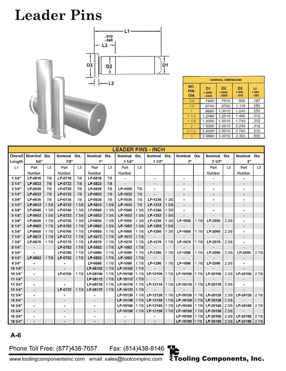
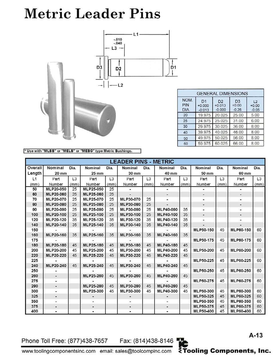
42 General Information Guide Pins Below are listed standard diameters and minimum/maximum lengths that we are able to machine to your specifi cations. We can also manufacture in-between diameters. We are able to make specials to meet your exact specifi catons. Please call, fax or for a quotation form. Every quote will be answered! Outside Diameter MINIMUM & MAXIMUM PIN S INCH Minimum Length Maximum Length Outside Diameter METRIC Minimum Length Maximum Length " 20" " 20" 18 & 19mm 25mm 500mm " 30" " 30" 24 & 25mm 25mm 760mm " 30" " 53" 30 & 32mm 50mm 1345mm " 53" " 53" " 53" " 53" 40 & 42mm 50mm 1345mm " 53" " 53" 50 & 52mm 75mm 1345mm " 53" " 53" " 53" " 53" 63mm 75mm 1345mm " 53" " 53" " 53" " 53" " 53" 80mm 100mm 1345mm " 53" " 53" " 53" " 53" " 53" " 53" 100mm 125mm 1345mm " 53" " 53" " 53" " 53" 115mm 125mm 1345mm " 53" " 53" " 53" " 53" 125mm 125mm 1345mm TN, ATN, TPB & TPC STRAIGHT PINS Lamina TPB & TPC Pins dimensions shown opposite for use in precision die sets. (Pins Available in Class 2) SHOULDER PINS For use with automotive, hardware, forming, or draw dies where stamping stock is thicker than 1/16, and clearances between punch and die sections will be more than.003 per side. (Pins available in Class 2) REMOVABLE PINS Designed specifi cally for all dies where it is desirable to remove pins for ease and simplicity of sharpening die. Lamina removable pins are generally used in carbide dies, progressive dies, lamination dies, and dies for very thin materials where clearances between punch and die sections will be no more than.0007 per side. Diameter TN Tolerance DIE PIN TOLERANCES Dimension ATN Tolerance HP Tolerance TPB & TPC Tolerance D2 Dimension TPC Press Tolerance Press Diameter
43 Guide Pins Pressed Fit ATN-175-X-6 GUIDE PIN STRAIGHT GUIDE PIN STRAIGHT with Step Lead TN-750-X-4 4 TN-125-X-7 7 TN-750-X-4-1/2 4-1/2 TN-125-X-7-1/2 7-1/2 TN-750-X-5 5 TN-125-X-8 8 3/4" TN-750-X-6 6 TN-125-X-8-1/2 8-1/2 TN-750-X-7 7 TN-125-X-9 1-1/4" 9 TN-750-X-8 8 TN-125-X-9-1/2 9-1/2 TN-100-X-4 4 TN-125-X TN-100-X-4-1/2 4-1/2 TN-125-X TN-100-X-5 5 TN-125-X TN-100-X-5-1/2 5-1/2 TN-150-X-5 5 TN-100-X-6 6 TN-150-X-5-1/2 5-1/2 TN-100-X-6-1/2 6-1/2 TN-150-X-6 6 1" TN-100-X-7 7 TN-150-X-6-1/2 6-1/2 TN-100-X-7-1/2 7-1/2 TN-150-X-7 7 TN-100-X-8 8 TN-150-X-7-1/2 7-1/2 TN-100-X-8-1/2 8-1/2 TN-150-X-8 1-1/2" 8 TN-100-X-9 9 TN-150-X-8-1/2 8-1/2 TN-100-x TN-150-X-9 9 TN-125-X-4-1/2 4-1/2 TN-150-X-9-1/2 9-1/2 TN-125-X-5 5 TN-150-X TN-125-X-5-1/2 1-1/4" 5-1/2 TN-150-X TN-125-X-6 6 TN-150-X TN-125-X-6-1/2 6-1/2 6 ATN-200-X ATN-175-X-6-1/2 6-1/2 ATN-200-X " ATN-175-X-7 7 ATN-200-X ATN-175-X-7-1/2 7-1/2 ATN-200-X ATN-175-X-8 8 ATN-250-X-8 8 ATN-175-X-8-1/2 8-1/2 ATN-250-X-8-1/2 8-1/2 ATN-175-X-9 9 ATN-250-X /4" ATN-175-X-9-1/2 9-1/2 ATN-250-X-9-1/2 9-1/2 ATN-175-X ATN-250-X /2" ATN-175-X ATN-250-X ATN-175-X ATN-250-X ATN-175-X ATN-250-X ATN-175-X ATN-250-X ATN-175-X ATN-250-X ATN-200-X-6 6 ATN-300-X-9 9 ATN-200-X-6-1/2 6-1/2 ATN-300-X ATN-200-X-7 7 ATN-300-X ATN-200-X-7-1/2 7-1/2 ATN-300-X ATN-200-X-8 8 ATN-300-X " 3" ATN-200-X-8-1/2 8-1/2 ATN-300-X ATN-200-X-9 9 ATN-300-X ATN-200-X ATN-300-X ATN-200-X-10-1/2 10-1/2 ATN-300-X ATN-200-X ATN-300-X TN and ATN pins are made of hardened steel with a precision-ground running diameter (), these guide pins are perfect mates for standard Lamina guide bushings. TN TN pins are centerless ground. ATN ATN pins are centerless ground. Please see bore size information on page
44 GUIDE PIN STRAIGHT PRESS FIT END UNGROUND Guide Pins Pressed Fit L2 L2 TPB-750-X-4 4 TPB-175-X-6 6 TPB-750-X-4-1/2 4-1/2 TPB-175-X-6-1/2 6-1/2 TPB-750-X-5 5 TPB-175-X-7 7 TPB TPB-750-X-5-1/2 5-1/2 TPB-175-X-7-1/2 7-1/2 3/4" 1-3/8" TPB-750-X-6 6 TPB-175-X-8 8 TPB-750-X-7 7 TPB-175-X-8-1/2 8-1/2 TPB-750-X-7-1/2 7-1/2 TPB-175-X-9 9 TPB-750-X-8 8 TPB-175-X-9-1/2 1-3/4" 9-1/2 2-1/4" TPB-100-X-4 4 TPB-175-X TPB-100-X-4-1/2 4-1/2 TPB-175-X TPB-100-X-5 5 TPB-175-X TPB-100-X-5-1/2 5-1/2 TPB-175-X TPB-100-X-6 6 TPB-175-X TPB-100-X-6-1/2 6-1/2 TPB-175-X " 1-1/2" TPB-100-X-7 7 TPB-175-X TPB-100-X-7-1/2 7-1/2 TPB-200-X-6 6 TPB-100-X-8 8 TPB-200-X-6-1/2 6-1/2 TPB-100-X-8-1/2 8-1/2 TPB-200-X-7 7 TPB-100-X-9 9 TPB-200-X-7-1/2 7-1/2 TPB-100-X TPB-200-X-8 8 L2 TPB-125-X-4 4 TPB-200-X-8-1/2 8-1/2 TPB-125-X-4-1/2 4-1/2 TPB-200-X-9 9 TPB-125-X-5 5 TPB-200-X-9-1/2 9-1/2 2" TPB-125-X-5-1/2 5-1/2 TPB-200-X /2" D2 TPB-125-X-6 6 TPB-200-X TPB-125-X-6-1/2 6-1/2 TPB-200-X TPB-125-X-7 7 TPB-200-X TPB-125-X-7-1/2 1-1/4" 7-1/2 1-3/4" TPB-200-X TPB-125-X-8 8 TPB-200-X TPB-125-X-8-1/2 8-1/2 TPB-200-X TPB-125-X-9 9 TPB-200-X TPB-125-X-9-1/2 9-1/2 TPB-250-X-8 8 TPB-125-X TPB-250-X-8-1/2 8-1/2 TPB-125-X TPB-250-X-9 9 TPB-125-X TPB-250-X TPB-150-X-4-1/2 4-1/2 TPB-250-X TPB-150-X-5 5 TPB-250-X /2" 3-1/2" TPB-150-X-5-1/2 5-1/2 TPB-250-X TPB-375-X TPB-150-X-6 6 TPB-250-X TPB-150-X-6-1/2 6-1/2 TPB-250-X /4" diameters TPB-150-X-7 7 TPB-250-X TPB-150-X-7-1/2 7-1/2 TPB-250-X & L2 lengths as specified TPB-150-X-8 8 TPB-250-X TPB-150-X-8-1/2 8-1/2 TPB-300-X /2" 2" TPB-150-X-9 9 TPB-300-X TPB-450-X TPB-150-X-9-1/2 9-1/2 TPB-300-X TPB-150-X TPB-300-X /2" diameters TPB-150-X TPB-300-X " 4" TPB-150-X TPB-300-X & L2 lengths as specified TPB-150-X TPB-300-X TPB-150-X TPB-300-X TPB-150-X TPB-300-X Call for quotation on pins above. TPB-150-X TPB-300-X All TPB Guide Pins have centers &.015 stock left on the D2 diameter for grinding. See bore size information on page
45 GUIDE PIN STRAIGHT PRESS FIT GROUND L2 L2 L2 TPC-750-X-4 4 TPC-150-X-8 8 TPC-300-X-9 9 TPC-750-X-4-1/2 4-1/2 TPC-150-X-8-1/2 8-1/2 TPC-300-X TPC-750-X-5 5 TPC-150-X-9 9 TPC-300-X TPC-750-X-5-1/2 5-1/2 TPC-150-X-9-1/2 1-1/2" 9-1/2 2" TPC-300-X TPC-750-X-6 3/4" 6 1-3/8" TPC-150-X TPC-300-X " TPC-750-X-6-1/2 6-1/2 TPC-150-X TPC-300-X TPC-750-X-7 7 TPC-150-X TPC-300-X TPC-750-X-7-1/2 7-1/2 TPC-175-X-6 6 TPC-300-X TPC-750-X-8 8 TPC-175-X-6-1/2 6-1/2 TPC-300-X TPC-875-X-4 4 TPC-875-X-4-1/2 4-1/2 TPC-175-X-7-1/2 7-1/2 TPC-875-X-5 5 TPC-175-X-8 8 TPC-875-X-5-1/2 5-1/2 TPC-175-X-8-1/2 8-1/2 TPC-875-X-6 7/ /2 TPC-175-X-9 9 TPC-875-X-6-1/2 6-1/2 TPC-175-X-9-1/2 1-3/4" 9-1/2 TPC-875-X-7 7 TPC-175-X TPC-875-X-7-1/2 7-1/2 TPC-175-X TPC-875-X-8 8 TPC-175-X TPC-100-X-4 4 TPC-175-X-7 7 TPC-300-X TPC-175-X TPC-100-X-4-1/2 4-1/2 TPC-175-X TPC-100-X-5 5 TPC-175-X TPC-100-X-5-1/2 5-1/2 TPC-175-X TPC-100-X-6 6 TPC-200-X-6 6 TPC-100-X-6-1/2 6-1/2 TPC-200-X-6-1/2 6-1/2 1" 1-1/2" TPC-100-X-7 7 TPC-200-X-7 7 TPC-100-X-7-1/2 7-1/2 TPC-200-X-7-1/2 7-1/2 TPC-100-X-8 8 TPC-200-X-8 8 TPC-100-X-8-1/2 8-1/2 TPC-200-X-8-1/2 8-1/2 TPC-100-X-9 9 TPC-200-X-9 9 TPC TPC-100-X TPC-200-X-9-1/2 9-1/2 2" TPC-125-X-4 4 TPC-200-X /2" TPC-125-X-4-1/2 4-1/2 TPC-200-X D2 TPC-125-X-5 5 TPC-200-X D2 Specifi cations: TPC-125-X-5-1/2 5-1/2 TPC-200-X TPC-100 & smaller = nominal plus TPC-125-X-6 6 TPC-200-X TPC = nominal plus TPC-125-X-6-1/2 6-1/2 TPC-200-X TPC-375 & 450 = nominal plus TPC-125-X-7 7 TPC-200-X TPC-125-X-7-1/2 1-1/4" 7-1/2 1-3/4" TPC-200-X TPC-125-X-8 8 TPC-250-X-8 8 TPC-375-X TPC-125-X-8-1/2 8-1/2 TPC-250-X-8-1/2 8-1/2 TPC-125-X-9 9 TPC-250-X /4" diameters TPC-125-X-9-1/2 9-1/2 TPC-250-X TPC-125-X TPC-250-X & L2 lengths as specified TPC-125-X TPC-250-X /2" 3-1/2" TPC-125-X TPC-250-X TPC-450-X TPC-150-X-4-1/2 4-1/2 TPC-250-X TPC-150-X-5 5 TPC-250-X TPC-150-X-5-1/2 5-1/2 TPC-250-X /2" diameters TPC-150-X-6 1-1/2" 6 2" TPC-250-X TPC-150-X-6-1/2 6-1/2 TPC-250-X TPC-150-X-7 7 TPC-150-X-7-1/2 7-1/2 Not all pins ground on centers. 2-1/4" L2 & L2 lengths as specified Call for quotation on pins above. 4" 25


46 Guide Pins Pressed Fit Metric Solid & Hollow These pins are made especially for automotive stamping companies. They conform to the standards agreed to by the North American Automotive Metric Standards group. AUTOMOTIVE METRIC NAAMS STANDARD 32, 40, 50 & 63 Dia. guide posts have M8 x thread; 80, 100, 115 & 125 Dia. guide posts have M12 x thread to facilitate handling from deep freeze. 26 SOLID Ground Unground G G G G G G G G G G G G G G G G G G G G G G G G G G G G G G G512512UG G512514UG G512516UG G512518UG G513214UG G513216UG G513218UG G513220UG G514014UG G514016UG G514018UG G514020UG G514022UG G514025UG G515016UG G515018UG G515020UG G515022UG G515025UG G515028UG G515031UG GUIDE PIN STRAIGHT NAAMS HOLLOW Ground Tol g D D2 Tol r D4 Hollow Pins Only G516318UG G516320UG G516322UG G416325UG G516328UG G516331UG G516335UG G516340UG G516350UG G G518022UG 225 G G G G G G G G G G G G G G G G G G G G G G G G G G518025UG G518028UG G518031UG G518035UG G518040UG G518045UG G518050UG G511031UG G511035UG G511040UG G511045UG G511050UG G511055UG G511060UG G511065UG G511140UG G511150UG G511235UG G511240UG G511245UG G511250UG G511255UG G511260UG G511265UG G511270UG 80 GH GH GH GH GH GH GH GH GH GH GH GH GH GH L L3 D2 HOLLOW PIN D4 M x 30mm L3 Please see bore size information on page 18.


47 Guide Pins Pressed Fit Metric GUIDE PINS STRAIGHT METRIC Nom Pin Dia Nom Pin Dia TN-19MM-X TN-25MM-X TN-19MM-X TN-25MM-X mm TN-19MM-X TN-25MM-X TN-19MM-X TN-25MM-X TN-19MM-X mm 160 TN-32MM-X TN-19MM-X TN-32MM-X TN-19MM-X TN-32MM-X TN-19MM-X TN-32MM-X TN-19MM-X TN-32MM-X TN-25MM-X TN-32MM-X TN-25MM-X TN-32MM-X mm 190 TN-25MM-X TN-32MM-X TN-25MM-X TN-32MM-X TN-25MM-X mm 160 TN-32MM-X TN-25MM-X TN-32MM-X TN-25MM-X TN-32MM-X TN-25MM-X TN-32MM-X TN-25MM-X TN -Metric TN pins are designed to be pressed into place. The ground bearing surface is equal top to bottom. TPB-40MM-X-130 STRAIGHT GUIDE PINS METRIC UNGROUND L2 TPB-50MM-X-260 L TPB-40MM-X TPB-50MM-X TPB-40MM-X TPB-50MM-X mm 300 TPB-40MM-X TPB-50MM-X TPB-40MM-X TPB-50MM-X TPB-40MM-X TPB-63MM-X TPB-40MM-X TPB-63MM-X TPB-40MM-X mm mm TPB-63MM-X TPB-40MM-X TPB-63MM-X TPB-40MM-X TPB-63MM-X mm TPB-40MM-X TPB-63MM-X TPB-40MM-X TPB-63MM-X TPB-40MM-X TPB-63MM-X TPB-40MM-X TPB-63MM-X TPB-40MM-X TPB-63MM-X TPB-50MM-X TPB-80MM-X TPB-50MM-X TPB-80MM-X TPB-50MM-X TPB-80MM-X TPB-50MM-X TPB-80MM-X mm mm 60mm TPB-50MM-X TPB-80MM-X TPB-50MM-X TPB-80MM-X TPB-50MM-X TPB-80MM-X TPB-50MM-X mm 80mm 100mm TPB - Metric L2 * *TPB pins have grind stock on the press fi t end. 27
48 Guide Pins Tap Fit Lamina demountable guide pins are tap fit and require toe clamps and screws to hold them in place. L5 The clamping flange is ground so that the flange fits squarely against the mounting surface. Please see pages 16 & 17 for toe clamp placement information and bore size information on page 18. D2 D3.187 L Heavy-duty X-40-Clamps are used to secure the pins to the die shoe. Clamps and screws are included. & D2 Nom Pin Dia D ±.010 L3 ±.010 GUIDE PINS DEMOUNTABLE L5 (Ref) NO. of CLAMPS & D2 Nom Pin Dia DGP DGP DGP DGP DGP DGP / DGP DGP DGP DGP DGP DGP DGP DGP DGP DGP DGP DGP DGP DGP DGP DGP DGP DGP DGP DGP DGP DGP DGP DGP DGP DGP DGP DGP DGP DGP DGP DGP / DGP DGP DGP DGP DGP DGP DGP DGP DGP DGP DGP DGP DGP DGP DGP DGP / DGP DGP DGP DGP DGP DGP DGP DGP DGP DGP DGP DGP DGP DGP DGP DGP / DGP DGP DGP DGP D ±.010 L3 ±.010 L5 (Ref) NO. of CLAMPS

49 Guide Pins Tap Fit Lamina demountable guide pins are tap fit and require toe clamps and screws to hold them in place. L5 The clamping flange is ground so that the flange fits squarely against the mounting surface. Please see pages 16 & 17 for toe clamp placement information and bore size information on page 18. D2 D3.187 L Heavy-duty X-40-Clamps are used to secure the pins to the die shoe. Clamps and screws are included. DGP1420 & D2 Nom Pin Dia D ± L3 ±.010 GUIDEPINS DEMOUNTABLE L5 (Ref) NO. of CLAMPS DGP2022 & D2 Nom Pin Dia DGP DGP DGP DGP DGP DGP DGP DGP DGP DGP DGP / DGP DGP DGP / DGP DGP DGP DGP DGP DGP DGP DGP DGP DGP DGP DGP DGP DGP DGP DGP DGP D ± L3 ±.010 L5 (Ref) DGP DGP DGP DGP DGP DGP DGP2418 DGP DGP DGP DGP DGP DGP DGP DGP DGP DGP DGP DGP DGP DGP DGP DGP DGP DGP DGP DGP DGP DGP DGP DGP DGP DGP DGP DGP DGP DGP / DGP NO. of CLAMPS

50 Guide Pins Pressed Fit Shoulder type guide pins are for use with automotive, hardware, forming, or draw dies where stamping stock is thicker than 1/16, and clearances between punch and die sections will be more than.003 per side. Shoulder type guide pins are also valuable for repair of damaged dies where straight type pins no longer fit. Nom Pin Dia. GUIDE PINS WITH SHOULDERS D2 Press Dia. (Pins available in Class 2) L2 Nom Pin Dia. D2 Press Dia. HP-100-X-5-1/2 5-1/2 HP-200-X-8 8 HP-100-X-6 6 HP-200-X-8-1/2 8-1/2 HP-100-X-6-1/2 6-1/2 HP-200-X-9 9 1" 1-1/2" 1-1/2" HP-100-X-7 7 HP-200-X HP-100-X-8 8 HP-200-X " 2-1/2" HP-100-X-9 9 HP-200-X /2" HP-125-X-6 6 HP-200-X HP-125-X-7 7 HP-200-X HP-125-X-7-1/2 1-1/4" 1-3/4" 7-1/2 2 HP-200-X HP-125-X-8 8 HP-200-X HP-125-X-9 9 HP-250-X-9 9 HP-150-X-6 6 HP-250-X HP-150-X-6-1/2 6-1/2 HP-250-X HP-150-X-7 7 HP-250-X /2" 3" HP-150-X-7-1/2 7-1/2 HP-250-X " HP-150-X-8 8 HP-250-X HP-150-X-8-1/2 8-1/2 HP-250-X /2" 2" 2-1/2" HP-150-X-9 9 HP-250-X HP-150-X HP-300-X HP-150-X HP-300-X HP-150-X HP-300-X-14 3" 3-5/8" 14 5" HP-150-X HP-300-X HP-150-X HP-300-X HP-175-X-7-1/2 7-1/2 HP-300RA-X HP-175-X-8 8 HP-300RA-X HP-175-X-9 9 HP-300RA-X " 3-1/2" 5" HP-175-X HP-300RA-X /4" 2-1/4" 3" HP-175-X HP-300RA-X HP-175-X HP-300RA-X HP-175-X HP Pins can be manufactured in 3 3 /4 and 4 1 /2 HP-175-X diameters in various lengths. See page 22. L2 L2 HP D2 D2 dimension is supplied with approximately.016 grindstock. HP Shoulder pins are meant to be press fit into place. 1/4 R 30


51 Guide Pins Tap Fit Metric Lamina has a wide variety of pins to meet most tool room requirements. Applications: Transfer Presses Repairs See page 17 for clamp placement instructions. GUIDE PINS WITH SHOULDERS METRIC Tol g6 D2 D2 Tol r6 D3 L3 L5 G G G G G G G G G G G G G G G G G G G G G G G G G G G G G G G L5 L3 6 32, 40, 50 & 63 Dia. guide posts have M8 x thread; 80, 100, 115 & 125 Dia. guide posts have M12 x thread to facilitate handling from deep freeze. D2 D3 Must be held in place with toe clamps. G720000C toe clamps & screws are included. See pages 16 & 17 for clamping information; bore size information on page


52 32 RP-100-X-5 GUIDE PIN REMOVABLE Nom. Pin Dia L2 Tapped Hole RP-100-X-5-1/ RP-100-X Pin End RP-100-X-6-1/ /16-18x3/4 RP-100-X " RP-100-X-7-1/ Install End /16-18 RP-100-X RP-100-X-8-1/ RP-100-X RP-125-X-5-1/ RP-125-X RP-125-X-6-1/ RP-125-X RP-125-X-7-1/ Pin End RP-125-X /16-18x7/8 RP-125-X-8-1/ " RP-125-X Install End /8-16 RP-125-X RP-125-X RP-125-X RP-125-X RP-125-X RP-150-X-5-1/ RP-150-X RP-150-X-6-1/ Pin End RP-150-X " /8-16x1 RP-150-X-7-1/ RP-150-X Install End 3/8-16 RP-150-X-8-1/ RP-150-X RP-150-X RP-175-X RP-175-X-7-1/ Pin End RP-175-X /8-16x " RP-175-X-8-1/ Install End RP-175-X / RP-175-X RP-200-X RP-200-X RP-200-X-7-1/ RP-200-X Pin End RP-200-X-8-1/ /8-16x7/8 RP-200-X " RP-200-X Install End /8-16 RP-200-X RP-200-X RP-200-X RP-200-X RP-250-X RP-250-X Pin End RP-250-X /2-13x " RP-250-X Pin End RP-250-X / RP-250-X RP-300-x " Non-Stock; call for quotation Guide Pins Removable Pressed Fit Bushing Liner Designed specifically for all dies where it is desirable to remove pins for ease and simplicity of sharpening die. Lamina removable pins are generally used with carbide dies, progressive dies, lamination dies, and dies for very thin materials where clearances between punch and die sections will be no more than.0007 per side. Can be used with Plain Bearing & Keyless Ball-Bearing Bushing and Retainers. ASSEMBLIES 3/8 L2 2 2 REMOVABLE PIN D2* BUSHING LINER END CAP SOCKET HEAD CAP Tapped Hole Pin End Tapped Hole Install End Ground for REMOVABLE PIN Unground Nom. Pin Dia. GRP-100-ASSY RP-100-ASSY GRP-125-ASSY RP-125-ASSY GRP-150-ASSY RP-150-ASSY GRP-175-ASSY RP-175-ASSY GRP-200-ASSY RP-200-ASSY GRP-250-ASSY RP-250-ASSY GRP-300-ASSY RP-300-ASSY Assembly includes 1 bushing liner, 1 End Cap & 1 Socket Head Cap Screw Ground BUSHING LINER for REMOVABLE PIN Unground Nom. Pin Dia. D2* O.D. Length GNRB-100 NRB GNRB-125 NRB GNRB-150 NRB GNRB-175 NRB GNRB-200 NRB GNRB-250 NRB GNRB-300 NRB *.016 stock left on this diameter on unground liner forgrindingtofitboredholeindieshoe END CAP for REMOVABLE PIN Nom. Pin Dia O.D. Soc Hd Screw RC-100- END-CAP /16-18x1 RC-125-END-CAP /8-16x1 RC-150-END-CAP /8-16x1 RC-175-END-CAP /8-16x1 RC-200-END-CAP /8-16x1 RC-250-END-CAP /2-13x1.5 RC-300-END-CAP /2-13x1.5 Removable pins, assemblies and screws are sold separately.


53 Stripper Bushings Clamp & Pressed Fit Types Lamina manufactures components specifi cally for use in dies where stripping operations take place such as in lamination dies. These components are made to close tolerances. Ground STRIPPER GUIDE PIN BUSHINGS BRONZE PLATED Assembly includes bushing, clamps and screws Nom. Bolt Pin D2 D3 D4 L2 Circle *Unground Dia. Dia. GCG-75 CG-75 3/4 GCG-100 CG *.016 grind stock on these diameters. No. "D" Clamps L2 D2* D D4 Ground STRIPPER BUSHINGS BRONZE PLATED PRESS FIT TYPE *Unground Nom. Pin Dia. GHG-62 HG-62 5/8 GHG-75 HG-75 3/4 GHG-100 HG D2 D D4 D2* *.016 grind stock on these diameters. Ground STRIPPER BUSHING STRAIGHT TYPE *Unground Nom. Pin Dia. GSG-100-L SG-100-L 1 *.020 grind stock on this diameter. D2 L D2* 34


54 Stripper Pins Pressed Fit & Flange Types STRIPPER PINS PRESS FIT TYPE Nom. Pin Dia. D2* L2 L SGP-62-X-4 5/ SGP-62-X-5 5/ SGP-75-X-5 3/ SGP-75-X-6-1/2 3/ SGP-100-X-6-1/ SGP-100-X-7-1/ *The D2 diameter is unground. Suggested finish grind size for D2 dimension to be.001 over nominal pin diameter. L2 L3.406 D2* 3/4 CG Type 1/4 G Screw DIE SHOE D3 STRIPPER PLATE DIE RETAINER DIE SHOE HG Type R1 L2 STRIPPER PIN & BUSHING APPLICATION Nom. Pin Dia. STRIPPER PIN FLANGE STYLE D2* ±.003 D3 L2 L3 R1 "G" Screws F / Flat Head F Soc. Head F Soc. Head F Soc. Head F / Soc. Head *The D2 diameter is unground. Suggested finsh bore size to be.005 over nominal pin diameter. 1 L3 D
55 HEAVY DUTY STOCK LIFTERS MODEL 75 HARDENED, GROUND AND VENTED Rockwell: RC Case Hardened Deep Packaged complete with spring, screw and retaining washer When ordering please specify: 1. Quantity 2. Catalog Number Lifters with travel greater than 1.75 are available. Priced on application. (Furnished without spring.) W Dia. R Dia. U T S V Radius PURPOSE Available as Replacement Part No. DL75 Die Life Retaining Washer. 6 per package. Includes fl at head socket screw 5/16-18x1. Note: In blanking die sections order optional Die Life DL Retaining Washers: Counterbore hole must be deeper. DIE LIFE REPLACEMENT RETAINING WASHER & SCREW KIT R S T U V W DL LIFTER SPECIFICATIONS A Operating Travel D Pocket Depth for Spring B Lifter Body Length E Spring Free Length C Pocket Depth for Lifter Body F Slot Length MODEL 75 Stock Lifter O.D (For Stock up to.094 thick) A TRAVEL B LIFTER C LIFTER POCKET D SPRING POCKET Replacement Washer #75WASHER Replacement Screw #75SCREW Die Life Package #DL75 (6 per package) E F SPRING FREE SLOT REPLACE- MENT DIE SPRING SPRING DEFLECT- ION M113L M115L M115AL M115BL M115CL M115DL 1.2 VALUES CONSTANT FOR ALL 75 LIFTERS a.578 Dimension between CL of Lifter Pocket to CL of Socket Screw b.203 Slot Depth ±.005 c.750 Pocket Diameter for Lifter Body d.688 Counter Bore Diameter for Lifter Washer f.25 Counter Bore Depth in Stripper Plate, minus half of stock thickness g.781 Counter Bore Diameter in Stripper Plate h.7495 Lifter Body Diameter i.125 Slot Height (for Stock) ±.005 j.187 Dimension from Top of Slot to Top of Body ±.005 k ˆLength of Spring Pocket in Lifter Body m.50 Spring Pocket Diameter n Dimension from Bottom of Washer (Slot) to Bottom of Body p.375 Counter Bore Depth for Washer & Socket Screw d Counterbore F n p.156 5/16-18 x 5/8 Socket Button Head Screw a.187 h g b c REAM i f j A Travel k E Counterbore in stripping plate B C D m 36
 W Dia. R Dia. U T S V PURPOSE Available as Replacement Part No.")
56 HEAVY DUTY STOCK LIFTERS MODEL 112 HARDENED, GROUND AND VENTED Rockwell: RC Case Hardened Deep Packaged complete with spring, screw and retaining washer When ordering please specify: 1. Quantity 2. Catalog Number Lifters with travel greater than 1.75 are available. Priced on application. (Furnished without spring.) W Dia. R Dia. U T S V PURPOSE Available as Replacement Part No. D12 Die Life Retaining Washer. 6 per package. Includes fl at head socket screw 3/8-16x1-1/4. Note: In blanking die sections order optional Die Life DL Retaining Washers: Counterbore hole must be deeper. DIE LIFE REPLACEMENT RETAINING WASHER & SCREW KIT R S T U V W D LIFTER SPECIFICATIONS A Operating Travel D Pocket Depth for Spring B Lifter Body Length E Spring Free Length C Pocket Depth for Lifter Body F Slot Length MODEL 112 Stock Lifter O.D (For Stock up to.156 thick) d Counterbore b c REAM A TRAVEL B LIFTER C LIFTER POCKET D SPRING POCKET E F SPRING FREE SLOT REPLACE- MENT DIE SPRING SPRING DEFLECT- ION M4L M6L M8L M10L M11BL M11CL a h g i f j Counterbore in stripping plate Replacement Washer #112 WASHER Replacement Screw #112 SCREW Die Life Package #D12 (6 per package) VALUES CONSTANT FOR ALL 112 LIFTERS a.828 Dimension between CL of Lifter Pocket to CL of Socket Screw b.329 Slot Depth ±.005 c Pocket Diameter for Lifter Body d.875 Counter Bore Diameter for Lifter Washer f.50 Counter Bore Depth in Stripper Plate, minus half of stock thickness g Counter Bore Diameter in Stripper Plate h Lifter Body Diameter i.188 Slot Height (for Stock) ±.005 j.406 Dimension from Top of Slot to Top of Body ±.005 k Length of Spring Pocket in Lifter Body m.75 Spring Pocket Diameter n Dimension from Bottom of Washer (Slot) to Bottom of Body p.394 Counter Bore Depth for Washer & Socket Screw F p n.156 3/8-16 x 1.00 Socket Button Head Screw A Travel k E B C D m 37
57 HEAVY DUTY RAIL STOCK LIFTER PINS MODEL T-750 HARDENED, GROUND AND VENTED Rockwell: RC Case Hardened Deep Package complete with spring, screw and retaining washer. When ordering please specify: 1. Quantity 2. Catalog Number 5/16-18 x.625 tap LIFTER SPECIFICATIONS A Operating Travel D Pocket Depth for Spring B Lifter Body Length E Spring Free Length C Pocket Depth for F Slot length Lifter Body G Top of Die to Top of Lifter Body d Counter bore c REAM Rail Stock Lifter O.D A TRAVEL B LIFTER C&D LIFTER POCKET G E SPRING FREE F SLOT Optional: Tack Weld at As- REPLACE- MENT DIE SPRING SPRING DEFLECTION T M113L 4.5 T M115L 3.0 T M115AL 2.5 T M115BL 2.1 T M115CL 1.4 T M115DL 1.2 Replacement Washer Part Number 75WASHER Replacement Screw Part Number 75SCREW G F p h a A Travel Rail & Screw Not Furnished B n k VALUES CONSTANT FOR ALL 75 -T LIFTERS a.578 Dimension between CL of Lifter Pocket to CL of Socket Screw c.750 Pocket Diameter for Lifter Body d.688 Counter Bore Diameter for Lifter Washer h.7495 Lifter Body Diameter C & D 5/16-18 x 5/8 Socket Button Head Screw E i.125 Slot Height (for Stock) ±.005 j.187 Dimension from Top of Slot to Top of Body ±.005 k n p ˆLength of Spring Pocket in Lifter Body Dimension from Bottom of Washer (Slot) to Bottom of Body.375 Counter Bore Depth for Washer & Socket Screw 38
58 HEAVY DUTY RAIL STOCK LIFTER PINS MODEL 112T HARDENED, GROUND AND VENTED Rockwell: RC Case Hardened Deep Package complete with spring, screw and retaining washer. When ordering please specify: 1. Quantity 2. Catalog Number 3/8-16 x 1 tap LIFTER SPECIFICATIONS A Operating Travel D Pocket Depth for Spring B Lifter Body Length E Spring Free Length C Pocket Depth for F Slot length Lifter Body G Top of Die to Top of Lifter Body d Counter bore c Ream Rail Stock Lifter O.D A TRAVEL B LIFTER C&D LIFTER POCKET G E F SPRING SLOT F.L. REPLACE- MENT DIE SPRING SPRING DEFLECTION 112T M4L T M6L T M8L T M10L T M11BL T M11CL 3.8 Replacement Washer Part Number 112WASHER Replacement Screw Part Number 112SCREW G F p.250 h a Optional Tack Weld at Assembly A Travel Rail & Screw Not Furnished.156 B n k VALUES CONSTANT FOR ALL 112-T LIFTERS a.828 Dimension between CL of Lifter Pocket to CL of Socket Screw c Pocket Diameter for Lifter Body d.875 Counter Bore Diameter for Lifter Washer h Lifter Body Diameter C & D 3/8-16 x 1.00 Socket Button Head Screw E i.188 Slot Height (for Stock) ±.005 j.406 Dimension from Top of Slot to Top of Body ±.005 k n p Length of Spring Pocket in Lifter Body Dimension from Bottom of Washer (Slot) to Bottom of Body.394 Counter Bore Depth for Washer & Socket Screw 39


59 Mini-Lifters Top or Side Mounted 3/8 and 1/2 diameters each to 3 different lengths. Hardened, ground and vented. Accurately machined from solid bar steel and packaged complete with spring, socket head cap screw, dog point screw and retaining washer. Immediately available from Inventory. ML ML ML OPTIONAL DIE LEVEL FULL SCALE TEMPLATE ML ML ML R.130 ± Air Relief.160 Width of slot 1 /4-20 Dog Pt. Screw & Lock Nut Ream.500 Dia. Dog Point Washer Note: Can be guided by dog point washer or dog point screw Dog Pt. Screw & Lock Nut.130 Width of Slot.38R.130 ± Ream.375 Dia. Air Relief.355 A TRAVEL B C BORE D MIN E F SPRING SLOT FREE REPLACE- MENT DIE SPRING 1/10" SPRING DEFLEC- TION ML M111L 6.8 ML M112L 5.5 ML M113L 4.5 A TRAVEL B C BORE D MIN E F SPRING SLOT FREE REPLACE- MENT DIE SPRING 1/10" SPRING DEFLEC- TION ML M101L 4.0 ML M102L 2.8 ML M103L Dia..12 ML Dia Dia..09 ML Dia B.54 Opt..10 A Travel.16 1 /4-20x.5 Screw.62 F B Opt. A Travel x.38 Screw.62 F C E D Min. 1 /8 Initial Spring Comp. 4 to 1 Ratio C E D Min. 40

60 Design in (and build in) stock lifters just as easily as you do die springs and pins. Standard notched lifters are made in two sizes to handle stock up to.156 thick. Side center-rail lifters that easily accept your special rails are also offered. These lifters all install from the top only. Easier to do and they can be replaced without taking the die from the press. All they need are two drilled holes, one tapped. Drop the spring and lifter in the larger one and secure them with the retaining screw in the tapped hole. Go to standard lifters for consistent quality they re all solid bar steel, hardened, ground and vented. You can t build them yourself for less T T T T T T T T T T T T-1-75 ML ML ML ML ML ML STOCKLIFTER REPLACEMENT S REPLACEMENT SPRING M113L M115L M115AL M115BL M115CL M115DL M4L M6L M8L M10L M11BL M11CL M101L M102L M103L M111L M112L M113L REPLACEMENT WASHERS REPLACEMENT SCREW DIELIFEKIT 6SETS 75WASHER 75SCREW DL75 75WASHER 75SCREW DL75 75WASHER 75SCREW DL75 75WASHER 75SCREW DL75 75WASHER 75SCREW DL75 75WASHER 75SCREW DL75 112WASHER 112SCREW D12 112WASHER 112SCREW D12 112WASHER 112SCREW D12 112WASHER 112SCREW D12 112WASHER 112SCREW D12 112WASHER 112SCREW D12 38WASHER 50WASHER 41

61 LIFTER PINS METRIC Lifter pins are manufactured from 1144 steel and are commonly used to handle large die sets. They conform to NAAMS standards. The internal spring provides added assurance that the fall ring will function properly during the course of the pin s use. NAAMS A B C D E F Total Die Wt. in Code (mm) (mm) (mm) (mm) (mm) (mm) Metric Tons (t) LP L LP L LP L LP L
 D (in) A (in) 20-150CSB 2.00 1.50 20-200CSB 2.00 2.00 2.00 20-250CSB 2.00 2.50 20-300CSB 2.00 2.00 3.00 20-350CSB 2.00 3.50 20-400CSB 2.00 4.00 20-425CSB 2.00 4.25 20-475CSB 2.")
62 STOP BLOCKS These stop blocks are precision machined from 1018 material. Additionally, the blocks are inspected to provide uniform quality and dimensions. The length dimension is.060 oversize. NO. Diameter Length (in) D (in) A (in) CSB CSB CSB CSB CSB CSB CSB CSB CSB CSB CSB CSB CSB CSB CSB CSB CSB CSB CSB CSB CSB CSB CSB CSB

63 PAD RETAINERS LOCKING INCH, STANDARD MOUNT Pad retainers are manufactured from 1144 steel and hardened to Rockwell C-scale. They are machined to precise tolerances in order to retain the pad and assure parallelism during use. The NP Series is also available, by special order, that offers three prongs as opposed to knurl. S1 Socket Set Screw S2 Socket Head Cap Screw Diam. Diam. Length ±.005 NO. (in) D2 (in) (in) L2 (in) L3 (in) L4 (in) S1 (in) S2 (in) /8 18 5/ /8 18 5/ /4 16 3/ /8 14 1/ ASSEMBLY INCLUDES: Retainer Body Socket Head Cap Screws Socket Set Screw LOAD RADIUS RATING NO. (in) lbs. 100-XXX.03 1, XXX.03 1, XXX.03 3, XXX.06 5, XXX.06 7, XXX.06 10,000 Diam. Diam. Length ±.005 NO. (in) D2 (in) (in) L2 (in) L3 (in) L4 (in) S1 (in) S2 (in) /8 14 1/ /8 12 5/ /4 12 3/


64 PAD RETAINERS LOCKING INCH, STANDARD MOUNT, WITH FLATS S1 Socket Set Screw S2 Socket Head Cap Screw Diam. Diam. Length ±.005 NO. (in) D2 (in) (in) L2 (in) L3 (in) L4 (in) S1 (in) S2 (in) F F F F F F /8 18 5/ F F F F F F F F F F F /8 18 5/ F F F F F F F F F F F F F F /4 16 3/ F F F F F F F F F F F F F F /8 14 1/ F F F F F F ASSEMBLY INCLUDES: Retainer Body Socket Head Cap Screws Socket Set Screw LOAD F RADIUS RATING NO. (in) (in) lbs. 100-XXX , XXX , XXX , XXX , XXX , XXX ,000 Diam. Diam. Length ±.005 NO. (in) D2 (in) (in) L2 (in) L3 (in) L4 (in) S1 (in) S2 (in)) F F F /8 14 1/ F F F F F F F F F F F /8 12 5/ F F F F F F F F F F F F F F F /4 12 3/ F F F F F F F
 (in) lbs. 100-XXXR.625.03 1,500 106-XXXR.690.03 1,500 125-XXXR.875.")

65 PAD RETAINERS LOCKING INCH, REVERSE MOUNT, WITH FLATS Pad retainers are manufactured from 1144 steel and hardened to Rockwell C-scale. They are machined to precise tolerances in order to retain the pad and assure parallelism during use. LOAD F RADIUS RATING NO. (in) (in) lbs. 100-XXXR , XXXR , XXXR , XXXR , XXXR , XXXR , Diam. Diam. Length ±.005 NO. (in) D2 (in) (in) G (in) L3 (in) T1 (in) R R R R R R R R R / R R R R R R R R R R R R R / R R R R R R R R R R R R R R / R R R R R R R R Diam. Diam. Length NO. ±.005 (in) D2 (in) (in) G (in) L3 (in) T1 (in) R R R R R R R R R / R R R R R R R R R R R R R / R R R R R R R R R R R R R R / R R R R R R R R R

 (mm) (mm) NR50-30 30 NR50-40 40 40 50 NR50-45 40 45 50 NR50-50 40 50 50 NR50-60 40 60")
66 PAD RETAINERS STANDARD AND REVERSE MOUNT METRIC Pad retainers are manufactured from 1144 steel and hardened to Rockwell C-scale. They are machined to precise tolerances in order to retain the pad and assure parallelism during use. S1 Socket Set Screw S2 Socket Head Cap Screw D2 L2 L3 S1 S2 LOAD RATING D2 L3 LOAD RATING NR M27 x 2 M16 x kn NR M36 x 3 M20 x kn NR NR kn 299 kn STANDARD MOUNT REVERSE MOUNT Diameter Length Diameter D2 (mm) (mm) (mm) NR NR NR NR NR NR NR NR NR NR NR NR NR NR NR NR NR NR NR NR NR NR NR NR NR NR NR Diameter Length Diameter D2 (mm) (mm) (mm) NR50-30R 30 NR50-40R NR50-45R NR50-50R NR50-60R NR50-65R NR50-70R NR50-75R NR50-90R NR50-100R 100 NR50-115R NR50-130R 130 NR50-140R NR50-160R 160 NR70-40R 40 NR70-45R NR70-50R NR70-60R NR70-65R NR70-70R NR70-75R NR70-90R NR70-100R NR70-115R NR70-130R NR70-140R NR70-160R

67 TRUSTED SOLUTIONS AND INNOVATION PINS & BUSHINGS INCH
68 PINS & BUSHINGS CONTENTS General Information PAGE Plain Bearing Guide Posts Removable Precision Guide Posts 1 Press Fit Commercial & Precision Guide Posts 2 Demountable Commercial & Precision Guide Posts 4 Oversize Shoulder Press Fit Guide Posts 6 Plain Bearing Bushings Demountable Low Profile Bronze-Plated Bushings 7 Demountable Bronze, Bronze-Plated & Steel Bushings (Extra Long, Standard and Short Shoulder Series) 8 Demountable Self-Lubricating Bushings 10 Oversize Shoulder Demountable Bushings 12 Press Fit Bushings 13 Mold/Machinery Press Fit Straight Bushings 14 Mold Components Self-Lubricating Shoulder Bushings 15 Mold Components - Self-Lubricating Ejector Bushings 16 Ball Bearing Components Ball Bearing Cages 17 Ball Bearing Demountable Guide Posts 18 Ball Bearing Press Fit Guide Posts 20 Ball Bearing Demountable Bushings 21 Ball Bearing Straight Sleeve Bushings 22 Bosses Demountable Bosses 23 Selection Guides Ball Bearing Components Selection Guide 24 Type I Component Selection Guide 25 Type II & III Component Selection Guide 27 Type II & III Bushing & Ball Cage Selection Guide 28 Technical Information Ball Bearing Components Technical Information 30 Plain Bearing Components Technical Information 31 Clamp Dimensions for Demountable Posts and Bushings 32 ii i


69 General Information As the premier die set manufacturer, we offer a complete line of catalog die sets as well as custom complex and simple sets. For replacement parts and for those customers wanting to assemble their own sets, an extensive line of catalog guide posts and bushings in both plain bearing and ball bearing styles is available for immediate delivery. Our plain bearing guide posts are available in press fit, demountable and removable styles. The press fit and demountable styles are available in commercial and precision series. Precision guide posts are hardened, ground and hard chrome plated to provide an exceptionally smooth, hard wearing surface as well as providing resistance to corrosion, less friction and maintenance of close working fits. Our plain bearing bushings are available in press fit and demountable styles and are equipped with figure 8 oil grooves and lubrication fittings. Our demountable bushings are available in three profiles, standard, short and extra long shoulder to give optimum flexibility in die set design. The bushings are also available in steel, bronze, bronze-plated and self-lubricating materials and are ideally suited for running with commercial and precision posts. All demountable bushings are pre-fitted to the same diameter guide posts to ensure that the bushings and guide posts of the same diameter are completely interchangeable. Demountable posts and bushings are tap fit into location and seat flush with the ground face of the punch holder or die shoe. They are held in place with toe clamps and screws which provide perfect alignment of the post and bushing with the bore perpendicular to the ground surface of the punch holder or shoe. The clamp and screws provide four times the holding power compared to pressed-in components, yet they can be easily removed and assembled thus simplifying die building and maintenance. Our demountable bushings and guide posts provide ease of assembly. Demountable bushings are secured to the punch holder with our clamps and screws, proving four times the holding power of pressed-in bushings. Specially-designed spiral patterns are drilled into our ball cages to control tracking and grooving. Special equipment spins ball bearings in place, then our ball cages move on to rigid quality inspection. The ball bearing system includes press fit and demountable guide posts, press fit sleeve and demountable bushings as well as ball cages. The ball bearing guide posts are manufactured from hardened steel to assure free rolling of balls and high wear resistance. Each post is drilled and tapped at the bottom for mounting of the ball cage washer assembly. This unique mounting method permits the ball cage, except when under preload, to freely rotate 360 around the guide post thus eliminating scoring or tracking of the guide post surface. The ball bearings are arranged in the cage in a spiral pattern which also minimizes tracking or grooving and assures uniform wear. ii
70 Removable Precision Guide Posts Product Features Removable guide posts are easily assembled and disassembled and are designed for use in applications where it is desirable to sharpen the die while still mounted in the die set. The posts are installed into the die set and locked into place with a steel taper lock pin. The lock pin can be driven out for easy post removal. Removable posts have a microme finish and are ideally suited for running with steel, bronze or self-lubricating bushings. They are manufactured from high quality hardened steel and finish ground for a high precision finish. The hard chrome finish provides an exceptionally smooth, hard wearing surface thus reducing friction between the post and bearing. Utilizing the microme guide posts will greatly improve the accuracy and working life of die sets as well as provide additional corrosion resistance NOTES: All removable guide posts are shipped with taper pin. Post Diameter A Length L Precision (in) (in) Part Number / / / / / / / / / /4 4 1/ /4 4 3/ / /4 5 1/ /4 1/4 5 1/ /4 5 3/ / /4 6 1/ / Post Diameter A Length L Precision (in) (in) Part Number 1 1/4 7 1/ / /4 8 1/ /4 1/ / / / /2 4 1/ /2 4 3/ / /2 5 1/ /2 5 1/ /2 5 3/ / /2 6 1/ / /2 7 1/ / /2 8 1/ / / / / / Post Diameter A Length L Precision (in) (in) Part Number 1 3/4 6 1/ / /4 7 1/ / /4 3/4 8 1/ / / / / / / / /
71 Press Fit Commercial and Precision Guide Posts Product Features Press fit guide posts are available in commercial and precision series. Both series are manufactured from high quality hardened steel and finish ground for a high precision finish and ideally suited for running with steel, bronze or self-lubricating bushings. The precision series has a hard chrome finish providing an exceptionally smooth, hard wearing surface thus reducing friction between the post and bearing. Utilizing the precision microme guide posts will greatly improve the accuracy and working life of die sets as well as provide additional corrosion resistance. Press Fit Dimensions Press fit Press fit Diameter A Diameter D Length C (in) (in) (in) 1/ /8* 5/ /8 3/ /8* 7/ / /2 1 1/ /4 1 1/ /4-2** 1 3/ / /2 2 1/ / /2 NOTES: See page 31 for die set boring specifications. DIMENSIONS: *C = 1" for , & **C = 1 ¾" for part numbers where L is less than or equal to 7", C=2" for part numbers where L=7 ½" or greater Diameter Length Precision Commercial A (in) L (in) Part Number Part Number 1/2 3 1/ / /2 4 1/ /2 4 1/ /2 1/2 4 3/ / /2 5 1/ /2 5 1/ / /8 4 1/ /8 4 1/ /8 4 3/ / /8 5 1/ / /4 3 1/ / /4 4 1/ /4 4 1/ /4 3/4 4 3/ / /4 5 1/ / / / / /8 4 1/ /8 4 1/ /8 4 3/ / /8 5 1/ /8 7/8 5 1/ /8 5 3/ / /8 6 1/ / /8 7 1/ /
72 Press Fit Commercial and Precision Guide Posts Diameter Length Precision Commercial A (in) L (in) Part Number Part Number / / / / / / / / / /4 4 1/ /4 4 3/ / /4 5 1/ /4 5 1/ /4 5 3/ / /4 6 1/ /4 1 1/ /4 7 1/ / /4 8 1/ / / / / /2 4 1/ /2 4 3/ / /2 5 1/ /2 5 1/ /2 5 3/ / /2 6 1/ / /2 7 1/ / /2 8 1/ / / / / / / / Diameter Length Precision Commercial A (in) L (in) Part Number Part Number 1 3/ /4 6 1/ / /4 7 1/ / /4 8 1/ / / / / / / / / / /2 8 1/ / / / /2 1/ / / / / /

73 Demountable Commercial and Precision Guide Posts Product Features Press fit guide posts are manufactured from high quality hardened steel and finish ground for a high precision finish and ideally suited for running with steel, bronze or self-lubricating bushings. The precision series has a hard chrome finish providing an exceptionally smooth, hard wearing surface thus reducing friction between the post and bearing. Utilizing the precision microme guide posts will greatly improve the accuracy and working life of die sets as well as provide additional corrosion resistance. Demountable posts are tap fit and held in place with toe clamps and screws. They can be removed and assembled multiple times without damaging or distorting the mounting holes in the die set thus simplifying die building and maintenance. Demountable posts are also used to replace press fit posts when the press fit hole has been damaged and the straight pin no longer fits securely in the hole. NOTES: All demountable guide posts are supplied with mounting clamps and screws. See pages 32 & 33 for clamping dimensions or to order additional toe clamps or mounting screws. Length of post must be specified from shoulder, not overall length. Add thickness of die holder to F dimension to find L dimension of assembled set. Dimension X is the minimum distance between inside surface of shoe and holder with bushing shoulder resting on screw head. The dimension varies with shoulder and short shoulder bushings. Post Shoulder Shoulder Press Fit Minimum Shut Height X (in) Diameter A Diameter B Length D Length E Bushing Style (in) (in) (in) (in) Shoulder Short Shoulder 7/8 1 3/ / / / / / / /64 1 1/4 1 9/ /16 2 3/4 1 9/16 1 1/2 1 7/ /16 2 3/4 1 9/16 1 3/4 2 1/ /16 2 3/4 1 3/ / /16 2 3/4 1 3/4 2 1/2 3 1/ /16 3 1/4 1 3/ / /16 3 1/4 1 3/4 4
74 Demountable Commercial and Precision Guide Posts Diameter Working A Length F Precision Commercial (in) (in) Part Number Part Number 7/8 2 3/ / /8 3 1/ /8 3 1/ /8 3 3/ / /8 4 1/ /8 4 1/ /8 4 3/ /8 5 1/ /8 5 3/ /8 6 1/ /8 6 3/ / / / / / / / / / / /4 2 3/ / /4 3 1/ /4 3 1/ /4 3 3/ / /4 4 1/ /4 4 3/ /4 1 1/4 5 1/ /4 5 3/ /4 6 1/ /4 6 3/ /4 7 1/ /4 8 1/ /4 9 1/ /4 10 1/ /2 2 3/ / /2 3 1/ /2 3 1/ /2 1/2 3 3/ / /2 4 1/ /2 4 3/ Diameter Working A Length F Precision Commercial (in) (in) Part Number Part Number 1 1/2 5 1/ /2 5 3/ /2 6 1/ /2 6 3/ /2 1/2 7 1/ /2 8 1/ /2 9 1/ /2 10 1/ /4 3 1/ / /4 4 1/ / /4 5 1/ / /4 6 1/ /4 7 1/ /4 8 1/ /4 9 1/ /4 11 1/ / / / / / / / / / / / /2 4 1/ / /2 5 1/ /2 6 1/ /2 7 1/ /2 1/2 8 1/ /2 9 1/ /2 10 1/ /2 13 1/ /2 16 1/ / / / / / / / / /

75 Oversize Shoulder Press Fit Guide Posts Product Features These oversize shoulder guide posts are manufactured from high quality hardened steel and often used with oversize shoulder bushings shown on page 12. The press fit diameters of these posts are the same as the press fit of the outside diameters of the oversize shoulder bushings, thus the same hole may be bored through the punch and die holder. The press fit diameters are " oversize to allow grinding stock to fit the bored hole Post Press Fit Press Fit Working Overall Commercial Diameter A Diameter B Length C Length D Length L Part (in) (in) (in) (in) (in) Number** 1 1 1/2 1 1/ / /2 1 1/2 3 1/ /2 1 1/ / /2 1/2 4 1/ /2 1 1/2 1 1/2 1 1/ / /2 1 1/2 5 1/ /2 1 1/ / /2 1 1/2 6 1/ /4 1 3/ /4 1 3/ /2 5 1/ /4 1 3/ /4 1 3/ /2 6 1/ /4 1 3/ /4 1 3/ /2 7 1/ /4 1 3/ /4 1 3/ /2 8 1/ /4 1 3/ / /8 4 5/ / /8 5 1/8 7 1/ / /8 5 5/ / /8 6 1/8 8 1/ / /8 6 5/ / /8 7 1/8 9 1/ / /8 7 5/ /4 2 1/4 2 7/8 4 5/8 7 1/ /4 2 1/4 2 7/8 5 1/ /4 1/4 7/8 5 5/8 8 1/ /4 2 1/4 2 7/8 3/4 2 1/4 2 7/8 6 1/ /4 2 1/4 2 7/8 6 5/8 9 1/ /4 2 1/4 2 7/8 7 1/ /2 3 3/8 4 5/ /2 3 3/8 5 5/ /2 3/8 6 5/ /2 3 3/ /2 3 3/8 7 5/ /2 3 3/8 8 5/ /2 3 3/8 9 5/ /2 3 1/4 3 7/8 5 1/ /2 3 1/4 3 7/8 6 1/ /2 1/4 7/8 7 1/ /2 3 1/4 3 7/8 1/2 1/4 3 7/8 8 1/ /2 3 1/4 3 7/8 9 1/ /2 3 1/4 3 7/8 10 1/ **PLEASE NOTE The -3 Commercial Parts are not inventoried, but are available as a special. 6

76 Demountable Low Profile Bronze-Plated Bushings Product Features These bronze-plated low profile demountable bushings are designed so that the main body of the bushing is contained within the punch holder while only a minimum of the bushing projects below the punch holder and into the die area. With minimal bushing projection, this model is ideal for dies running in presses with automatic transfer devices. Since the bushings do not need removed during grinding, it is well suited for applications that require often die sharpening. All bushings are also equipped with oil grooves and lubrication fittings. Demountable bushings are tap fit into location and seat flush with the ground face of the punch holder. The bushings are held in place with toe clamps and screws which provide perfect alignment of the bushing with the bore perpendicular to the ground surface of the punch holder. The clamp and screws provide four times the holding power compared to pressed-in bushings, yet they can be easily removed and assembled thus simplifying die building and maintenance NOTES: All demountable bushings are supplied with mounting clamps and screws. See pages 32 & 33 for clamping dimensions or to order additional toe clamps or mounting screws. Post Bushing Diameters Press Fit Shoulder Overall Bronze-Plated Diameter Length E Length F Length L Part A (in) B (in) C (in) C1 (in) (in) (in) (in) Number 1 1 1/ /8 1/2 1 3/ / /8 1/2 1 7/ / /8 1/2 2 7/ /4 1 3/ /8 1/2 1 3/ /4 1 3/ /8 1/2 2 3/ /4 1 3/ /8 1/2 3 3/ / /8 1/2 2 3/ / /2 1 1/ /8 1/2 3 3/ /4 1/ /8 1/2 2 7/ /4 2 1/ /2 1 3/4 2 1/ /8 1/2 3 7/ / /8 1/2 2 7/ / / / /8 1/2 3 7/ / /8 1/2 3 1/ / /8 1/2 4 1/ / /8 1/2 5 1/

77 Demountable Bushings Bronze, Bronze-Plated & Steel & Product Features These demountable bushings are available in three profiles: standard, short and extra long shoulder to give optimum flexibility in die set design. The bushings are also available in steel, bronze and bronze-plated materials and are ideally suited for running with commercial and precision posts. All demountable bushings are prefitted to the same diameter guide posts to ensure that the bushings and guide posts of the same diameter are completely interchangeable. Demountable bushings are tap fit into location and seat flush with the ground face of the punch holder. The bushings are held in place with toe clamps and screws which provide perfect alignment of the bushing with the bore perpendicular to the ground surface of the punch holder. The clamp and screws provide four times the holding power compared to pressed-in bushings, yet they can be easily removed and assembled thus simplifying die building and maintenance. All bushings are equipped with figure 8 oil grooves and lubrication fittings. The bronze and bronze-plated demountable bushings offer superior resistance to seizure, the major cause of bushing wear. They are recommended in high speed applications and in applications with hide side thrust loads. EXTRA LONG SHOULDER Post Bushing Diameters Press Fit Shoulder Overall Steel Bronze Diameter Length E Length F Length L Part Plated Part A (in) B (in) C (in) C1(in) (in) (in) (in) Number Number 1 1 1/ / / /4 1 3/ / / / / / /4 2 1/ / / / / / /2 3 1/ / / / / / NOTES: All demountable bushings are supplied with mounting clamps and screws. See pages 32 & 33 for clamping dimensions or to order additional toe clamps or mounting screws. 8
 B (in) C (in) C1(in) (in) (in) (in) Number Number Number 3/4 1 1/8 1.175 1.300 11/16 1 3/4 2 7/16 6-06-64 7/8 1 3/8 1.422 1.547 11/16 1 3/4 2 7/16 6-07-64 1 1 1/2 1.720 1.")

 B (in) C (in) C1(in) (in) (in) (in) Number Number 3/4 1 1/8 1.175 1.300 11/16 3/4 1 7/16 6-06-63 7/8 1 3/8 1.422 1.547 11/16 3/4 1 7/16 6-07-63 1 1 1/2 1.720 1.")
78 Demountable Bushings Bronze, Bronze-Plated & Steel & STANDARD SHOULDER Post Bushing Diameters Press Fit Shoulder Overall Steel Bronze Bronze Diameter Length E Length F Length L Part Plated Part Part A (in) B (in) C (in) C1(in) (in) (in) (in) Number Number Number 3/4 1 1/ /16 1 3/4 2 7/ /8 1 3/ /16 1 3/4 2 7/ / /16 1 3/4 2 11/ /4 1 3/ / / / / / /4 2 1/ / / / / / /2 3 1/ /8 2 1/2 4 3/ / /8 2 1/2 4 3/ & SHORT SHOULDER Post Bushing Diameters Press Fit Shoulder Overall Steel Bronze Diameter Length E Length F Length L Part Plated Part A (in) B (in) C (in) C1(in) (in) (in) (in) Number Number 3/4 1 1/ /16 3/4 1 7/ /8 1 3/ /16 3/4 1 7/ / /16 13/16 1 3/ /4 1 3/ /8 13/ / / /16 13/ /4 2 1/ / / / / / /2 3 1/ / / / / /

79 Demountable Self-Lubricating Bushings GS100-15G Product Features These demountable self-lubricating bushings are available in standard and short profiles and are ideally suited for running with commercial and precision posts. They are manufactured from cast aluminum bronze material and are prefitted to the same diameter guide posts to ensure that the bushings and guide posts of the same diameter are interchangeable. Self-lubricating bushings contain graphite plugs which are impregnated with oil. When the bushings reach F as a result of friction between the bushing and guide post, oil is drawn from the plug thus lubricating the wear surface. A dark smear pattern is created on the wear surface as the oil and graphite are imbedded into the bronze or steel grain. This provides the lubrication necessary for continuous performance of the tool. Demountable bushings are tap fit into location and seat flush with the ground face of the punch holder. The bushings are held in place with toe clamps and screws which provide perfect alignment of the bushing with the bore perpendicular to the ground surface of the punch holder. The clamp and screws provide four times the holding power compared to pressed-in bushings, yet they can be easily removed and assembled thus simplifying die building and maintenance. SHORT SHOULDER Post Bushing Diameters Press Fit Shoulder Overall Self-Lubricating Diameter Length E Length F Length L Part A (in) B (in) C (in) C1 (in) (in) (in) (in) Number 1/2 1 9/16 1 3/4 1 3/8 1/2 1 7/8 GS100-15G 1 1 1/2 1 3/4 1 9/16 1/2 1 1/2 1 9/16 1 3/4 2 3/8 1/2 2 7/8 GS100-23G 1/4 3/4 1 15/16 2 1/8 1 7/8 1/2 2 3/8 GS125-19G 1 1/4 1 3/4 2 1/8 1 15/16 1/2 1/4 3/4 1 15/16 2 1/8 2 7/8 1/2 3 3/8 GS125-27G 1/2 1 3/16 2 3/8 1 7/8 1/2 2 3/8 GS150-19G 1 1/ /8 2 3/16 1/2 1/2 1 3/16 2 3/8 2 7/8 1/2 3 3/8 GS150-27G 3/4 1/4 2 7/16 2 5/8 2 3/8 1/2 2 7/8 GS175-23G 1 3/4 2 1/4 2 5/8 2 7/16 1/2 1 3/4 2 1/4 2 7/16 2 5/8 3 3/8 1/2 3 7/8 GS175-31G 1/2 2 3/4 2 15/16 2 3/8 1/2 2 7/8 GS200-23G 2 2 1/2 2 15/16 2 3/4 1/ /2 2 3/4 2 15/16 3 3/8 1/2 3 7/8 GS200-31G 2 1/ /16 3 3/8 2 5/8 3/8 3 GS250-24G 2 1/ /16 3/8 3 3/16 3/8 3 5/8 3/8 3/8 4 GS250-32G 2 1/ /16 3 3/8 4 5/8 3/8 5 GS250-40G 3 3 1/2 3 11/16 3 7/8 2 5/8 3/8 3 GS300-24G 1/2 3 11/16 3 7/8 3 5/8 3/8 4 GS300-32G 3 3 1/2 3 7/8 3 11/16 3/8 1/2 3 11/16 3 7/8 4 5/8 3/8 5 GS300-40G 3 3 1/2 3 11/16 3 7/8 5 5/8 3/8 6 GS300-48G 3 3/4 4 1/2 4 7/8 4 11/16 6 5/8 3/8 7 GS375-56G 4 1/2 5 1/2 5 11/16 5 7/8 4 5/8 3/8 5 GS450-40G 4 1/2 5 1/2 5 7/8 5 11/16 3/8 1/2 1/2 5 11/16 5 7/8 7 5/8 3/8 8 GS450-64G 10
 (in) (in) Number 1 1 1/2 1 3/4 1 27/32 15/16 1 3/4 2 11/16 G00 1 1/4 1 3/4 1 15/16 2 3/32 1 1/8 2 3 1/8 G25 1 1/2 2 2 3/16 2 11/32 1 3/16 2 3 3/16 G50 1 3/4 2 1/4 2 1/2 2 21/32 1 3/8 2 3 3/8 G75")
80 Demountable Self-Lubricating Bushings G00 STANDARD SHOULDER Post Bushing Diameters Press Fit Shoulder Overall Self-Lubricating Diameter Length E Length F Length L Part A (in) B (in) C (in) C1 (in) (in) (in) (in) Number 1 1 1/2 1 3/4 1 27/32 15/16 1 3/4 2 11/16 G00 1 1/4 1 3/4 1 15/16 2 3/32 1 1/ /8 G25 1 1/ / /32 1 3/ /16 G50 1 3/4 2 1/4 2 1/2 2 21/32 1 3/ /8 G /2 2 29/32 3 1/16 1 5/ /8 GD /2 3 1/4 3 21/ /16 1 7/8 2 1/2 4 3/8 GD /4 4 3/16 4 9/32 1 7/8 2 1/2 4 3/8 GD300 NOTES: Until the lubrication process begins, a light 20 wt. oil should be applied to pre-lube the wear surface of the bushing. All demountable bushings are supplied with mounting clamps and screws. See pages 32 & 33 for clamping dimensions or to order additional toe clamps or mounting screws. 11

81 Oversize Shoulder Demountable Bushings NOTES: & All demountable bushings are supplied with mounting clamps and screws. See pages 32 & 33 for clamping dimensions or to order additional toe clamps or mounting screws. Product Features Oversize shoulder bushings are available in standard and short shoulder profiles and available in steel, bronze and bronze-plated materials. They are often used in special die sets in conjunction with oversize shoulder guide posts shown on page 6. The press fit diameters of these bushings are the same as the press fit of the outside diameters of the oversize shoulder posts, thus the same hole may be bored through the punch and die holder. The press fit diameters are " oversize to allow grinding stock to fit the bored hole. The steel or bronze bushings may be ground for tap fit and installed with clamps and screws or may also be ground for a press fit. The bronze-plated bushings are for use as demountable bushings only and are supplied with the appropriate number of clamps and screws. These bushings should not be honed. If more clearance is desired, it is recommended to grind the working diameter of the shoulder guide post. **PLEASE NOTE The -21 Bronze Plated Parts are not inventoried, but are available as a special. SHORT SHOULDER STANDARD SHOULDER SHORT SHOULDER Post Bushing Diameters Press Fit Shoulder Overall Steel Bronze Diameter Length E Length F Length L Part Plated Part A (in) B (in) C (in) C1(in) (in) (in) (in) Number Number** 1 1 1/ /16 13/16 1 3/ /4 1 3/ /8 13/ / / /16 13/ /4 2 1/ / / / / / /2 3 1/ / / STANDARD SHOULDER Post Bushing Diameters Press Fit Shoulder Overall Steel Bronze Bronze Diameter Length E Length F Length L Part Plated Part Part A (in) B (in) C (in) C1(in) (in) (in) (in) Number Number Number 1 1 1/ /16 1 3/4 2 11/ /4 1 3/ / / / / / /4 2 1/ / / / / / /2 3 1/ /8 2 1/2 4 3/

82 Press Fit Bushings Product Features These press fit bushings are available in short shoulder, short sleeve and long sleeve profiles. Manufactured from high quality hardened steel, the bushings are finish ground for a press fit. Bushings 1 ¾" in diameter and smaller are finish ground " under listed inside diameters to allow for honing at assembly. Bushings with inside diameters 2" and larger are finished ground to decimal diameters. EXTRA LONG SLEEVE (-3) bushings include lubrication fitting and and grease grooves. SHORT SLEEVE (-1) bushings include grease grooves but do not have a lubrication fitting & NOTE: The press fit bushings shown on this page must be honed to fit the guide post. These bushings are finished undersized on the inside diameter to allow for fitting of the guide post. If it is desired to receive these bushings honed to a finished inside diameter a -H must be entered at the end of the part number. EXAMPLE: H to receive a bushing with an inside diameter that does not require additional fitting for guide post. Care still needs to be taken to not collapse the inside diameter of the bushing when pressing the bushing into a plate. EXTRA LONG SLEEVE SHORT SLEEVE Post Outside Overall Diameter A Diameter B Length L Part (in) (in) (in) Number 1/2 13/ / /4 1 1/ /8 1 3/ / /4 1 3/ / /4 2 1/ / /2 3 1/ Post Outside Overall Diameter A Diameter B Length L Part (in) (in) (in) Number 1/2 13/16 1 1/ / / /4 1 1/8 1 3/ /8 1 3/8 1 3/ /2 1 3/ /4 1 3/ / SHORT SHOULDER Post Press Fit Bushing Press Fit Shoulder Overall Diameter A Diameter B Diameter C Length E Length F Length L Part (in) (in) (in) (in) (in) (in) Number 1/2 13/ /16 13/16 1 1/ / /16 13/16 1 1/ /4 1 1/ /16 13/16 1 3/ /8 1 3/ /16 13/16 1 3/


83 Mold/Machinery Press Fit Straight Bushings MS Product Features These press fit self-lubricating bushings are manufactured from high quality self lubricated aluminum bronze material and are ideally suited for running with commercial and precision posts. Self-lubricating bushings contain graphite plugs which are impregnated with oil. When the bushings reach F as a result of friction between the bushing and guide post, oil is drawn from the plug thus lubricating the wear surface. A dark smear pattern is created on the wear surface as the oil and graphite are imbedded into the bronze or steel grain. This provides the lubrication necessary for continuous performance of the tool. NOTES: Until the lubrication process begins, a light 20 wt. oil should be applied to pre-lube the wear surface of the bushing. Guide Post Outside Overall Diameter A Diameter C Length L Part (in) (in) (in) Number /8 MS / /8 MS / /2 MS / /4 MS / / /2 MS /4 MS /8 MS /2 MS /4 MS MS MS / /4 MS / /8 MS / /2 MS / /4 MS / /8 MS / MS / MS / /4 MS / /8 MS / /2 MS / /4 MS / /8 MS / MS MS Guide Post Outside Overall Diameter A Diameter C Length L Part (in) (in) (in) Number 1 3/ /4 MS / /2 MS / /4 MS /4 3/ MS / /2 MS / MS / /2 MS / MS /4 MS /2 MS MS /2 MS MS /8 MS / /2 MS / MS / / /2 MS / MS / /2 MS / MS / / MS / /8 MS MS /2 MS MS /2 MS /8 MS


84 Mold Components Self-Lubricating Shoulder Bushings Product Features These press fit self-lubricating bushings are manufactured from high quality self lubricated aluminum bronze material and are ideally suited for running with commercial and precision posts. Self-lubricating bushings contain graphite plugs which are impregnated with oil. When the bushings reach F as a result of friction between the bushing and guide post, oil is drawn from the plug thus lubricating the wear surface. A dark smear pattern is created on the wear surface as the oil and graphite are imbedded into the bronze or steel grain. This provides the lubrication necessary for continuous performance of the tool. S G Post Press Fit Outside Press Fit Overall Self- Diameter Diameter Diameter Length Length Lubricating A (in) B (in) C (in) E (in) L (in) Part No. 3/ /16 7/8 S750-7G 3/ /16 1 3/8 S750-11G 3/ /16 1 7/8 S750-15G 3/ /16 2 3/8 S750-19G 3/ /16 2 7/8 S750-23G 3/ /16 3 3/8 S750-27G 3/ /16 3 7/8 S750-31G 3/ /16 4 3/8 S750-35G 3/ /16 4 7/8 S750-39G 7/ /16 7/8 S875-7G 7/ /16 1 3/8 S875-11G 7/ /16 1 7/8 S875-15G 7/ /16 2 3/8 S875-19G 7/ / /16 2 7/8 S875-23G 7/ /16 3 3/8 S875-27G 7/ /16 3 7/8 S875-31G 7/ /16 4 3/8 S875-35G /16 7/8 S1000-7G /16 1 3/8 S G /16 1 7/8 S G /16 2 3/8 S G /16 2 7/8 S G /16 3 3/8 S G /16 3 7/8 S G /16 4 3/8 S G /16 4 7/8 S G /16 5 7/8 S G 1 1/ /16 7/8 S1250-7G 1 1/ /16 1 3/8 S G 1 1/ /16 1 7/8 S G 1/ /16 2 3/8 S G 1 1/ / /16 2 7/8 S G 1 1/ /16 3 3/8 S G 1 1/ /16 3 7/8 S G 1 1/ /16 4 3/8 S G Post Press Fit Outside Press Fit Overall Self- Diameter Diameter Diameter Length Length Lubricating A (in) B (in) C (in) E (in) L (in) Part No. 1/ /16 4 7/8 S G 1 1/ / /16 5 7/8 S G 1 1/ /16 7/8 S1500-7G 1 1/ /16 1 3/8 S G 1 1/ /16 1 7/8 S G 1 1/ /16 2 3/8 S G 1/ /16 2 7/8 S G 1 1/ / /16 3 3/8 S G 1 1/ /16 3 7/8 S G 1 1/ /16 4 3/8 S G 1 1/ /16 4 7/8 S G 1 1/ /16 5 7/8 S G /16 1 3/8 S G /16 1 7/8 S G /16 2 3/8 S G /16 2 7/8 S G /16 3 3/8 S G /16 3 7/8 S G /16 4 3/8 S G /16 4 7/8 S G /16 5 7/8 S G 2 1/ /16 1 3/8 S G 2 1/ /16 1 7/8 S G 2 1/ /16 2 3/8 S G 2 1/ /16 2 7/8 S G 2 1/ /16 3 3/8 S G 2 1/ /16 3 7/8 S G 2 1/ /16 4 3/8 S G 2 1/ /16 4 7/8 S G 2 1/ /16 5 7/8 S G /16 3 3/8 S G /16 3 7/8 S G /16 4 7/8 S G /16 5 7/8 S G 15


85 Mold Components Self-Lubricating Ejector Bushings ME1000L Product Features Mold component products feature self-lubricating aluminum bronze bushings ideally suited for running with the MP line of Guide Posts. These self-lubricating bushings contain graphite plugs which are impregnated with oil. When the bushings reach F as a result of friction between the bushing and guide post, oil is drawn from the plug thus lubricating the wear surface. A dark smear pattern is created on the wear surface as the oil and graphite are imbedded into the bronze or steel grain. This provides the lubrication necessary for continuous performance of the tool. Part Nom. Number I.D. D (in) A (in) B (in) C (in) (in) L (in) ME750 3/ /2 ME875 7/ /2 ME /8 1 3/ ME1000L /8 2 ME / /8 1 3/4 1 1/ ME1250L 1/ /8 2 1/2 ME / /8 1 3/4 1 1/ ME1500L 1/ /8 2 1/2 ME /8 2 1/4 16


86 Ball Bearing Cages Product Features Ball cages are manufactured from a heat treated aluminum alloy which provides tough, wear resistant qualities. The ball bearings are vacuum degassed quality, fatigue resistant steel and are inspected to ensure roundness, smoothness and dimensional conformance. The ball bearings are arranged in the cage in a spiral pattern to minimize tracking or grooving and assure uniform wear. Ball cages are mounted to drilled and tapped guide posts by a special washer assembly which permits the cage to rotate freely around the guide post when not under pre-load TYPE I For Type I Ball Bearing Bushing Assembly TYPE II For Type II and Type III Ball Bearing Bushing Assemblies Posts Length Type I Type II Diameter C S X Part Part O (in) (in) (in) (in) Number Number 1 1 1/2 7/16 3/ /16 3/ /16 3/ /2 1 5/16 3/ / /16 3/ /4 1 13/16 3/ /2 2 1/16 3/ /4 2 5/16 3/ /4 1 1/2 7/16 3/ /4 2 11/16 3/ /4 2 3/4 1 7/16 3/ /4 3 1/4 1 11/16 3/ /4 3/16 1 1/4 3 3/4 1 15/16 3/ / /16 3/ /4 4 1/4 2 7/16 3/ /4 4 3/4 2 15/16 3/ /2 2 11/16 1/ /2 2 1/2 15/16 1/ /2 2 3/4 1 7/16 1/ /2 3 1/2 1 13/16 1/ /2 4 1/4 2 3/16 1/ /2 4 1/2 2 7/16 1/ / /16 1/ /2 5 1/2 3 7/16 1/ / /16 1/ /4 2 1/2 15/16 1/ / /16 1/ /4 1/4 1 3/4 3 1/4 1 11/16 1/ / /16 1/ Posts Length Type I Type II Diameter C S X Part Part O (in) (in) (in) (in) Number Number 1 3/4 4 3/4 2 7/16 1/ /4 5 1/4 2 15/16 1/ /4 5 3/4 3 7/16 1/ /4 6 1/4 3 15/16 1/ /4 6 3/4 4 7/16 1/ /16 1/ /2 1 7/16 1/ /4 1 15/16 1/ /2 2 5/16 1/ /4 2 11/16 1/ / /8 3 1/16 1/ /16 1/ /2 3 15/16 1/ /16 1/ /2 4 15/16 1/ / /16 3/ /2 5 3/4 3 3/ /2 6 1/2 3 3/8 3/ /2 7 1/4 3 3/4 3/ /2 7 3/4 4 1/4 3/ /2 8 1/4 4 3/4 3/ /2 8 3/4 5 1/4 3/ /16 3/ /4 3 3/ /2 3 3/8 3/ /4 3 3/4 3/ /4 4 1/4 3/ /4 4 3/4 3/ /4 5 1/4 3/
87 Ball Bearing Demountable Guide Posts Product Features Precision ball bearing guide posts are manufactured from hardened steel to assure free rolling of balls and high wear resistance. Each post is drilled and tapped at the bottom for mounting of the ball cage washer assembly. This unique mounting method permits the ball cage, except when under pre-load, to freely rotate 360 degrees around the guide post thus eliminating scoring or tracking of the guide post surface. Demountable posts are tap fit and held in place with toe clamps and screws. They can be removed and assembled multiple times without damaging or distorting the mounting holes in the die set thus simplifying die building and maintenance. Demountable posts are also used to replace press fit posts when the press fit hole has been damaged and the straight pin no longer fits securely in the hole. NOTES: All Ball Cage washer assembly sold separately and dependent on Type I, II or III assembly methods. Refer to page 30 for washer assembly part numbers. All demountable guide posts are supplied with mounting clamps and screws. See pages 32 & 33 for clamping dimensions or to order additional toe clamps or mounting screws. 18
88 Ball Bearing Demountable Guide Posts Diameter Diameter Press Fit Working O B Length Length Part (in) (in) E1 (in) F1 (in) Number 1 1 5/16 1 3/16 2 1/ /16 1 3/16 2 3/ /16 1 3/ /16 1 3/16 3 1/ /16 1 3/16 3 1/ /16 1 3/16 3 3/ /16 1 3/ /16 5/16 1 3/16 3/16 4 1/ /16 1 3/16 4 1/ /16 1 3/16 4 3/ /16 1 3/16 5 1/ /16 1 3/16 5 3/ /16 1 3/16 6 1/ /16 1 3/16 6 3/ /16 1 3/16 7 1/ /16 1 3/16 7 3/ /4 1 9/16 1 3/16 3 1/ /4 1 9/16 1 3/16 3 1/ /4 1 9/16 1 3/16 3 3/ /4 1 9/16 1 3/ /4 1 9/16 1 3/16 4 1/ /4 1 9/16 1 3/16 4 1/ /4 1 9/16 1 3/16 4 3/ /4 1/4 1 9/16 9/16 1 3/16 3/16 5 1/ /4 1 9/16 1 3/16 5 3/ /4 1 9/16 1 3/16 6 1/ /4 1 9/16 1 3/16 6 3/ /4 1 9/16 1 3/16 7 1/ /4 1 9/16 1 3/16 7 3/ /4 1 9/16 1 3/16 8 3/ /4 1 9/16 1 3/16 9 3/ /4 1 9/16 1 3/ / /2 1 7/8 1 7/16 3 1/ /2 1 7/8 1 7/16 3 1/ /2 1 7/8 1 7/16 3 3/ /2 1 7/8 1 7/ /2 1 7/8 1 7/16 4 1/ /2 1 7/8 1 7/16 4 1/ /2 1 7/8 1 7/ /2 1 7/8 1 7/16 5 1/ /2 1 7/8 1 7/ /2 1 7/8 1 7/16 6 1/ /2 1 7/8 1 7/ /2 1 7/8 1 7/16 7 1/ /2 1 7/8 1 7/ /2 1 7/8 1 7/16 8 1/ /2 1 7/8 1 7/ /2 1 7/8 1 7/16 9 1/ /2 1 7/8 1 7/ /2 1 7/8 1 7/ / /2 1 7/8 1 7/ /2 1 7/8 1 7/ / /2 1 7/8 1 7/ / /4 2 1/4 1 11/16 3 3/ /4 2 1/4 1 11/ /4 3/4 2 1/4 1/4 1 11/16 11/16 4 1/ /4 2 1/4 1 11/16 4 1/ /4 2 1/4 1 11/16 4 3/ /4 2 1/4 1 11/16 5 1/ /4 2 1/4 1 11/16 5 3/ Diameter Diameter Press Fit Working O B Length Length Part (in) (in) E1 (in) F1(in) Number 1 3/4 2 1/4 1 11/16 6 1/ /4 2 1/4 1 11/16 6 3/ /4 2 1/4 1 11/16 7 1/ /4 2 1/4 1 11/16 7 3/ /4 2 1/4 1 11/16 8 1/ /4 2 1/4 1 11/16 8 3/ /4 3/4 2 1/4 1/4 1 11/16 11/16 9 1/ /4 2 1/4 1 11/16 9 3/ /4 2 1/4 1 11/ / /4 2 1/4 1 11/ / /4 2 1/4 1 11/ / /4 2 1/4 1 11/ / /4 2 1/4 1 11/ / /4 2 1/4 1 11/ / /4 2 1/4 1 11/ / /2 1 15/16 4 1/ /2 1 15/16 4 1/ /2 1 15/16 4 3/ /2 1 15/ /2 1 15/16 5 1/ /2 1 15/16 5 1/ /2 1 15/16 5 3/ /2 1 15/ /2 1 15/16 6 1/ /2 1 15/ /2 1 15/16 7 1/ /2 1 15/ /2 1 15/16 8 1/ /2 1 15/ /2 1 15/16 9 1/ /2 1 15/ /2 1 15/ / /2 1 15/ /2 1 15/ /2 1 15/ /2 1 15/ /2 1 15/ /2 1 15/ /2 3 1/ / /2 3 1/ /16 6 1/ /2 3 1/ / /2 3 1/ / /2 3 1/ / /2 1/32 15/ /2 3 1/ /16 1/2 1/32 15/ /2 3 1/ / /2 3 1/ / /2 3 1/ / /2 2 7/ /2 2 7/16 6 1/ /2 2 7/16 7 1/ /2 2 7/16 8 1/ /2 2 7/16 9 1/ /2 7/ / /2 2 7/16 1/2 7/ / / / /2 2 7/ / /2 2 7/ /
89 Ball Bearing Press Fit Guide Posts Product Features Precision ball bearing guide posts are manufactured from hardened steel to assure free rolling of balls and high wear resistance. Each post is drilled and tapped at the bottom for mounting of the ball cage washer assembly. This unique mounting method permits the ball cage, except when under pre-load, to freely rotate 360 degrees around the guide post thus eliminating scoring or tracking of the guide post surface NOTES: Ball Cage washer assembly sold separately and dependent on Type I, II or III assembly methods. Refer to page 30 for washer assembly part numbers. Diameter Length Part O (in) L (in) Number 1 3 1/ / / / / / / / / / / /4 4 1/ /4 4 3/ /4 5 1/ /4 5 1/ /4 5 3/ / /4 6 1/ /4 1/ /4 7 1/ / /4 8 1/ / / / / /2 4 1/ / /2 5 3/ /2 1/ /2 6 1/ / Diameter Length Part O (in) L (in) Number 1 1/2 7 1/ / /2 8 1/ / /2 9 1/ / /2 10 1/ / /2 11 1/ / /2 12 1/ / / / /4 5 3/ /4 6 1/ / /4 7 1/ / /4 8 1/ / /4 9 1/ /4 3/ /4 10 1/ / /4 11 1/ / /4 12 1/ / / / / / / / / / Diameter Length Part O (in) L (in) Number / / / / / / /2 8 3/ /2 9 1/ / / / / / / / / / /
90 Ball Bearing Demountable Bushings Product Features These demountable bushings are tap fit into location and seat flush with the ground face of the punch holder. The bushings are held in place with toe clamps and screws which provide perfect alignment of the bushing with the bore perpendicular to the ground surface of the punch holder. The clamp and screws provide four times the holding power compared to pressed-in bushings, yet they can be easily removed and assembled thus simplifying die building and maintenance Post Overall Diameter Bushing Diameters Length E Length F Length Part (in) A (in) B (in) C (in) C1 (in) (in) (in) (in) Number 1 1 3/8 1 7/8 2 1/ /16 1 1/4 2 7/ /8 7/8 2 1/ /16 1 3/4 2 15/ /8 1 7/ / /8 1 7/8 2 1/ /16 2 1/4 3 7/ /8 1 7/8 2 1/ /16 2 3/4 3 15/ /4 1 5/8 2 1/8 2 3/ /16 1 3/4 2 15/ /4 1 5/8 2 1/ / /16 2 1/4 3 7/ /4 1 5/8 2 1/8 2 3/ /16 2 3/4 3 15/ /2 1 7/8 2 1/2 2 7/ /16 1 1/2 2 15/ /2 7/8 1/2 2 7/ /16 2 1/4 3 11/ /2 1 7/8 2 1/ /16 1/2 7/8 1/2 2 7/ / / /2 1 7/8 2 1/2 2 7/ /16 3 1/2 4 15/ /4 2 1/8 2 3/4 3 1/ /16 1 3/4 3 7/ /4 2 1/8 2 3/ / /16 2 1/2 4 3/ /4 2 1/8 2 3/4 3 1/ /16 3 1/4 4 15/ /2 3 1/4 3 5/ / / /2 3 1/4 3 5/ /16 2 3/4 4 11/ /2 3 1/ / /16 3 1/2 5 7/ /2 3 1/4 3 5/ /16 4 1/4 6 3/ /2 3 1/4 3 5/ / / / /4 4 1/ / / / / / / / / /4 4 1/ /16 4 3/4 6 11/ / /4 4 1/ /16 5 1/2 7 7/ /2 4 1/4 4 3/ / / / /2 4 1/ / / /2 4 1/4 4 3/ /16 4 3/4 6 11/ /2 4 1/4 4 3/ /16 5 1/2 7 7/

91 Ball Bearing Straight Sleeve Bushings Product Features Straight sleeve bushings are manufactured from high quality hardened steel and the bushings are finish ground for a press fit. Like all ball bearing components, these straight sleeve bushings are completely interchangeable. INSTALLATION INSTRUCTIONS In order to avoid the bushing close-in which occurs as a result of pressfit, these bushings should be retained with Danly Bushing Mount. When so installed, it is not necessary to hone the bushing bore after installation, and the bushing fit will be correct. APPLICATION OF DANLY BUSHING MOUNT 1. Degrease bushing OD and die shoe bore with alcohol, acetone or other volatile solvent and wipe dry. 2. Apply Bushing Mount sparingly and wring bushing into die shoe. 3. Allow a 4-hour cure at 72 F. Do not disturb bushing until cure is complete. DANLY BUSHING MOUNT: Part number Post Diameter Bushing Diameters Length Part (in) A (in) B (in) L2 (in) Number 1 1 3/8 1 7/8 2 1/ /8 1 7/ /8 7/8 3 1/ /8 1 7/ /8 1 7/ /8 1 7/8 4 1/ /8 1 7/ /4 1 5/8 2 1/ /4 1 5/8 2 1/8 3 1/ /4 1 5/8 2 1/ /4 1 5/8 2 1/8 1/4 5/8 1/8 4 1/ /4 1 5/8 2 1/ /4 1 5/8 2 1/ /2 1 7/8 2 1/ /2 1 7/8 2 1/2 3 3/ /2 1 7/8 2 1/2 4 1/ /2 7/8 1/ /2 1 7/8 2 1/2 1 1/2 1 7/8 2 1/2 5 1/ /2 1 7/8 2 1/ /2 1 7/8 2 1/ /2 1 7/8 2 1/ /4 2 1/8 2 3/4 3 1/ /4 2 1/8 2 3/4 4 1/ /4 2 1/8 2 3/4 3/4 1/8 3/ /4 2 1/8 2 3/4 5 1/ Post Diameter Bushing Diameters Length Part (in) A (in) B (in) L2 (in) Number 1 3/4 2 1/8 2 3/ /4 1/8 3/ /4 2 1/8 2 3/4 1 3/4 2 1/8 2 3/ /4 2 1/8 2 3/ /2 3 1/ /2 3 1/4 4 3/ /2 3 1/4 5 1/ /2 1/4 6 1/ /2 3 1/ /2 3 1/ /2 3 1/ /2 3 1/ /2 3 1/ / / / /4 6 3/ / /4 7 1/ / /4 1/2 3/4 8 1/ / /4 9 1/ / /4 10 1/ /2 4 1/ /2 4 1/4 6 3/ /2 1/4 7 1/ /2 4 1/4 1/2 1/4 8 1/ /2 4 1/4 9 1/ /2 4 1/4 10 1/


 (in) (in) (in)")
92 This illustration shows how the D (bolt circle) dimension is obtained & Demountable Bosses Product Features Demountable bosses are ideal for heavy duty applications and are available for guide posts from 2" in diameter and larger. The bosses are available in three styles. Type 1 is a combination bushing and guide post support. Type 2 is a boss bushing which is flange mounted with the major bearing surface contained within the die set. Type 3 is also classified as a boss-bushing type but with the guide post bearing surface extended below the mounting flange. TYPE 1 Demountable Boss Part Number A K Post Bushing B C D E F L (in) (in) Support Boss (in) (in) (in) (in) (in) (in) (in)2 1 1/ /32 21/32 5/ / / /32 21/32 5/ /16 5 1/ /16 2 1/2 1 1/ /32 5/ /16 2 1/2 3 1/ /32 5/ /16 5 1/ / / /16 25/32 5/ / /16 25/32 5/16 5 1/ /16 TYPE 2 Boss Bushings A K Part Number B C D E F L (in) (in) (in) (in) (in) (in) (in) (in) 2 1 1/ /2 17/32 2 1/ /2 1 1/ /8 21/ /2 TYPE 3 Boss Bushings A K Part Number B C D E F L (in) (in) (in) (in) (in) (in) (in) (in) 2 2 1/ /2 17/32 1 1/ /2 2 1/ /8 21/ /2 23
93 Ball Bearing Components Selection Guide Product Features For proper post, bushing and cage selection, the operating conditions of the die must be taken into consideration. Factors such as press speed, shut height, stroke length and operating environment all play a role in selecting the appropriate operating condition to give the best performance possible of your components. The operating conditions include full pre-load, pre-load relieved and total disengagement. Type I Full Pre-Load Throughout Stroke Type I component assemblies ensure that all ball bearings remain in constant contact with the guide post and bushing throughout the entire press stroke. This assembly is recommended for higher speed, short stroke dies. Type II Pre-Load Relived or Partially Relieved Type II component assemblies are designed so the ball cage never leaves the bushing; however the guide post disengages the bushing at the beginning of each stroke. This assembly is often preferred as pinch points are eliminated and foreign matter cannot get inside the assembly and damage the components. This assembly is often utilized in medium and long stroke dies. Type III Total Disengagement of Cage from Bushing Type III component assemblies are designed so the ball cage totally disengages from the bushing. This assembly is utilized on long stroke applications. 24
94 Type I Component Selection Guide Post Diam. Z E U1 U2 (in) (in) (in) (in) (in) 1 5/16 1 3/16 1/16 1/8 1 1/4 5/16 1 3/16 1 1/2 3/8 1 7/16 1 3/4 3/8 1 11/16 1/16 1/8 2 3/8 1 15/16 2 1/2 1/2 1 15/16 3 1/2 1 15/16 PRESS FIT POSTS 1. Calculate L, the desired guide post length, using one of the following 2 formulas: Assembly with Straight Sleeve Bushings: L=T-U 2 -Z Assembly with Demountable Bushings: L=T-U 1 -Z-J+E 2. Select a post length from the catalog that is equal to L calculated above. If the calculated L value is not a standard catalog length, you have two options. Choose the next longest length and cut off to the calculated L dimension or select a shorter length and recess the post in the punch holder to obtain correct L dimension. Note: Press fit length should be equal to or greater than the diameter of the guide post. DEMOUNTABLE POSTS 1. Calculate F 1, the desired guide post length, using one of the following 2 formulas: Assembly with Straight Sleeve Bushings: F 1 =T-U 2 -Z-K (Note F+J+K+Y<T) Assembly with Demountable Bushing: F 1 =T-U 1 -Z-J+E-K (Note L 2 +K+Y<T) 2. Select a post length from the catalog that is equal to F 1 calculated above. If the calculated F 1 value is not a standard catalog length, choose a catalog length that is close to but less than the calculated F 1. Note: Demountable posts cannot be cut off. BUSHING & CAGE SELECTION Selection of a Type 1 ball bearing bushing and cage assembly is based on the required stroke and the guide post diameter. 1. Determine the guide post diameter required and the stroke required. 2. Using the selection chart on page 26, find the desired stroke. Move down this column to the colored square on the horizontal line opposite the required post diameter. 3. Select the required bushing length which is listed to the left of the selected square in the columns labeled Demountable Shoulder and Straight Sleeve. Note: For applications with no off-center loading, select the bushing with the shortest overall length from the selection chart. However for longer stroke applications or where side-loading may be present select the bushing with the longest possible length to provide optimal guidance. 4. Select the required cage length which is also listed to the left of the selected square in the column labeled Ball Cage. Note: Shut height permitting, select the longest cage length possible for optimal performance. NOTES: If die grind is not required, stroke may be increased by the amount of die grind allowance, dimension X, found in the right most column of the selection chart. NOTES: A die set designed for a particular stroke may be used in any press of lesser stroke but never in any press where the stroke is greater than originally chosen. 25

95 Type I Component Selection Guide 26


96 Type II & III Component Selection Guide PRESS FIT POSTS 1. Calculate L, the desired guide post length, using one of the following 2 formulas: Assembly with Straight Sleeve Bushings: L=T-U 2 -Z Assembly with Demountable Bushings: L=T-U 1 -Z-J+E 2. Select a post length from the catalog that is equal to L calculated above. If the calculated L value is not a standard catalog length, you have two options. Choose the next longest length and cut off to the calculated L dimension or select a shorter length and recess the post in the punch holder to obtain correct L dimension. Note: Press fit length should be equal to or greater than the diameter of the guide post. DEMOUNTABLE POSTS 1. Calculate F 1, the desired guide post length, using one of the following 2 formulas: Assembly with Straight Sleeve Bushings: F 1 =T-U 2 -Z-K (Note F+J+K+Y<T) Assembly with Demountable Bushings: F 1 =T-U 1 -Z-J+E-K (Note L 2 +K+Y<T) 2. Select a post length from the catalog that is equal to F 1 calculated above. If the calculated F 1 value is not a standard catalog length, choose a catalog length that is close to but less than the calculated F 1. Note: Demountable posts cannot be cut off. BUSHING & CAGE SELECTION Selection of a Type II and Type III ball bearing bushing and cage assembly is based on the required stroke and the guide post diameter. 1. Determine the guide post diameter required and the stroke required. 2. Determine the desired operating condition or the extent to which the cage leaves the bushing. 3. Determine if a demountable or straight sleeve bushing is to be used. 4. Using the selection chart on pages 28 & 29, find the desired stroke (S). Move down this column to the colored square on the horizontal line opposite the required post diameter. Find the colored square in the desired operating condition. 5. Select the required bushing length which is listed to the left of the selected square in the columns labeled DemountableShoulder or Straight Sleeve. Note: For applications with no off-center loading, select the bushing with the shortest overall length from the selection chart. However for longer stroke applications or where side-loading may be present select the bushing with the longest possible length to provide optimal guidance. 6. Select the required cage length which is also listed to the left of the selected square in the column labeled Ball Cage. Note: Shut height permitting, select the longest cage length possible for optimal performance. 27 Post Diam. Z E U1 U2 Y O (in) (in) (in) (in) (in) (in) 1 15/32 1 3/16 39/64 1 1/4 15/32 1 3/16 1 1/2 1/2 1 7/16 1 3/4 1/2 1 11/16 1/16 1/16 1/8 3/4 2 1/2 1 15/16 2 1/2 9/ /16 3 9/ /16 NOTES: A die set designed for a particular stroke may be used in any press of lesser stroke but never in any press where the stroke is greater than originally chosen.

97 CAUTION Be sure bushing does not strike punch holder at minimum shut height. If this condition exists, use shorter bushing and corresponding ball cage. COLOR CODE FOR SELECTION GUIDE Type II and III components provide Type I operating conditions Type II & III Bushing & Ball Cage Selection Guide Nom. Ball Bushing Ball Post Diam. Demountable Shoulder Straight Sleeve Cage O E F U1 L2 U2 C 1 1 3/16 1 1/4 2 7/16 1/16 2 1/2 1/ /4 2 15/ /2 2 1/4 3 7/16 3 1/ /16 2 3/4 3 15/16 1/16 4 1/8 3 1/4 4 1/2 3 1/ /4 1 1/4 1 3/16 1 3/4 2 15/16 1/16 3 1/8 2 3/4 2 1/4 3 7/16 3 1/2 3 1/4 1 1/4 1 3/16 2 3/4 3 15/16 4 1/16 1/8 3 3/4 4 1/ / /4 1 1/2 1 7/16 1 1/2 2 15/16 1/16 3 1/8 2 3/4 2 1/4 3 11/16 3 3/4 3 1/2 Partial Pre-load 1 1/2 1 7/ /16 4 1/2 4 1/4 3 1/2 4 15/16 1/16 5 1/8 4 1/ /2 8 6 Pre-load Relieved 1 3/4 1 11/16 1 3/4 3 7/16 1/16 3 1/2 1/8 3 1/4 2 1/2 4 3/16 4 1/ /4 4 15/ /4 1 3/4 1 11/16 1/16 6 1/8 5 1/ / / / / /16 1/16 4 1/8 3 3/4 2 3/4 4 11/16 4 3/4 4 1/2 3 1/2 5 7/16 5 1/2 5 1/4 Unlimited stroke cage leaves bushing /16 4 1/4 6 3/16 6 1/4 5 5/8 1/16 1/ / / /2 NOTES: Sleeve Bushing: L 2 + K must be less than T Shoulder Bushing: J + F + K must be less than T 2 1/2 1 15/ /16 1/16 6 1/8 5 3/4 4 3/4 6 11/16 6 3/4 6 1/2 2 1/2 1 15/16 5 1/2 7 7/16 7 1/2 1/16 1/8 7 1/4 8 1/2 7 3/4 9 1/2 8 1/4 10 1/2 8 3/4 Demountable Bushing: Maximum F = T - J - K Sleeve Bushing: Maximum L 2 = T - K / / /16 1/16 6 1/8 5 3/4 4 3/4 6 11/16 6 3/4 6 1/2 5 1/2 7 7/16 7 1/2 7 1/4 1/16 1/8 8 1/2 7 3/4 9 1/2 8 1/4 10 1/2 8 3/4
98 Ball Cage C Type II & III Bushing & Ball Cage Selection Guide 1/ / /2 STROKE S AT MINIMUM SHUT HEIGHT (DIE LIFE DEPLETED) 3 3 1/ / / / / V 2 7/8 2 1/2 1 1/ /4 3 1/2 3 3/4 3 1/4 1 3/8 3 1/2 3 3/4 2 3/4 1 1/4 3 1/4 1 1/2 3 3/4 3 3/ /4 4 3/ /4 4 1/4 4 3/4 2 3/4 1 1/4 3 2/3 1 5/8 4 1/4 4 1/4 4 1/2 4 1/ /2 5 1/ /4 1 1/ /8 4 3/4 4 3/4 5 1/4 5 1/4 5 3/4 52 3/4 1/4 6 1/4 6 1/4 6 3/4 6 3/4 3 3/4 1 3/4 4 1/2 1 1/8 5 1/4 5 1/4 5 5/8 5 5/ / / /2 6 1/ /2 5 3/4 2 11/16 6 1/2 3 1/16 7 1/4 7 1/4 7 3/4 8 1/4 8 3/4 7 3/4 3 7/16 8 1/4 8 3/4 5 3/4 6 1/2 7 1/4 7 3/4 8 1/4 8 3/ /16 3 1/16 7 1/4 7 3/4 3 7/16 8 1/4 8 3/4

99 Ball Bearing Components Technical Information BORING SPECIFICATIONS FOR BALL BEARING GUIDE POSTS AND BUSHINGS Post Bore Sizes (in) Diameter Punch Holder for Posts Die Shoe for Bushings A (in) Minimum Maximum Minimum Maximum / / / / BALL CAGE WASHER ASSEMBLY Snap Ring- Nominal Washer Assembly Bushing Hex Head Ball Bearing Post Part Number Stop Washer-Retainer Stop Washer Screw Cages Diameter Type I Type II Type Type Type Type Type A (in) Assembly Assembly I II and III II and III I, II and III II and III / /16-18 x 3/ / / /8-16 x 7/ / /2-13 x NOTES: TYPE I Assembly includes stopwasher retainer and head hex screw. TYPE II Assembly includes stopwasher retainer, bushing stopwasher, hex head screw and snap ring. BUSHING MOUNT Part Number Volume oz. NOTES: A bushing mount is used when installing straight sleeve ball bearing bushings to avoid bushing close-in as a result of press-fit. BALL CAGE WASHER ASSEMBLY Guide Post Tap Sizes Required Seating Torque Diameter O (in) Tap Size Lbs per Inch Lbs per Foot 1 1 1/4 5/16 18 N.C /2 2 3/8 10 N.C /2 3 1/2 13 N.C Ball Bearing Bushing Lubrication Recommendation During operation of Ball Bearing Bushing Assembly, add lubricant once each 8-hour shift by spray or brush application. Use a refined mineral oil of viscosity 290/ F (39 C) containing EP additives and rust inhibitors. 30
100 Plain Bearing Components Technical Information BORING SPECIFICATIONS FOR PLAIN BEARING GUIDE POSTS AND BUSHINGS Post Bore Sizes (in) Diameter Die Shoe for Posts Punch Holder for Bushings A (in) Minimum Maximum Minimum Maximum 1/ / / / / / / / LUBRICANT INFORMATION Part Number Volume Quart Gallon NOTES: For improved component life, lubricant should be applied to bushings during operation. Lubricant is sold by the quart or gallon. ID TOLERANCE FOR PRE-FITTED DEMOUNTABLE BUSHINGS Diameter ID Tolerance A (in) (in) Minimum Maximum 3/ / / / / /

101 Clamp Dimensions for Demountable Posts & Bushings FIGURE A FIGURE B FIGURE C FIGURE D NOTES: S FOR 3-CLAMP FOR 4-CLAMP ARRANGEMENT ARRANGEMENT Figure B clamp schematic is for part number only and supplied on low profile demountable bushings 1-1/2" diameter and larger. All other assemblies are supplied with Figure A style clamps. Posts and bushings are automatically supplied with the appropriate number of mounting clamps and screws. A (L-R Feed) B (F-B Feed) C (Round Dies) (Center Post Sets) CLAMP DIMENSIONS FOR GUIDE POSTS - Plain Bearing & Ball Bearing Clamps & Screw Socket Head screws Post Clamp Part Cap Screw req'd Radius Radius Diam. Part Number Description per C D T M N P A (in) Number S Bushing (in) (in) (in) (in) 7/ /4-20x3/4 long /32 39/64 3/4 1 1/16 27/ /4-20x3/4 long /32 39/64 13/16 1 1/8 7/8 1 1/ /16-18x7/8 long /4 63/ / / /16-18x7/8 long /4 1 1/8 1 17/32 1 1/16 1 3/ /16-18x7/8 long /4 1 19/ /64 1 3/ /16-18x7/8 long /4 1 27/ /64 1 9/16 2 1/ /16-18x7/8 long /4 1 43/64 2 5/ / /16-18x7/8 long /4 1 59/ / /32 32
TRUSTED SOLUTIONS AND INNOVATION PINS & BUSHINGS INCH
 www.danly.com TRUSTED SOLUTIONS AND INNOVATION PINS & BUSHINGS INCH www.danly.com PINS & BUSHINGS INCH Service We Deliver and Quality You Can Depend On DANLY IEM is a leading manufacturer of die sets and
PINS & BUSHINGS INCH
 www.danly.com TRUSTED SOLUTIONS AND INNOVATION PINS & BUSHINGS INCH Steel, Bronze & Self-Lubricating Friction & Ball Bearing Components www.danly.com PINS & BUSHINGS INCH Strategically located to serve
CONTENTS. Gold Bond Fasteners Bolts 1 Clamps 3 Nuts 4 Washers 5. Hoist Rings Center Pull 6 Side Pull 7. Socket Head Stripper Bolts Inch 8 Metric 9
 CONTENTS PAGE NUMBER Gold Bond Fasteners Bolts 1 Clamps 3 Nuts 4 Washers 5 Hoist Rings Center Pull 6 Side Pull 7 Socket Head Stripper Bolts Inch 8 Metric 9 Punch Holder Shanks 10 Roller Stock Guides 11
TOOLING COMPONENTS. tel fax Clamping Kits Step Blocks...7. Driver Studs...
 Clamping Kits... 2-8 Step Blocks...7 Driver Studs... 9-13 Bolts, Screws... 14-20 Nuts, Washers... 21-29 Sex Bolts... 30-31 Clamps... 32-44 Screws... 45-49 Knobs & Levers... 49-53 Rest Pads...54 Index Plungers...
Tuf-Lite and Tuf-Lite II Fans 6000M Series Hub
 Tuf-Lite and Tuf-Lite II Fans 6000M Series Hub INSTALLATION MANUAL Adjustable Pitch Fan Assembly 32.8 or 10 Meter Diameter Hudson Tuf-Lite and Tuf-Lite II fan blades Hudson Tuf-Lite (black) fan blades
Swagelok Thermoplastic Hose Hand Swager User s Manual
 Swagelok Thermoplastic Hose Hand Swager User s Manual Thermoplastic Hose Hand Swager User s Manual Contents Hand Swager Components....................... 2 Setup Swager.......................................
Tuf-Lite and Tuf-Lite II Fans 6000 Series Hub
 Tuf-Lite and Tuf-Lite II Fans 6000 Series Hub INSTALLATION MANUAL Adjustable Pitch Fan Assembly 32 and 33 Diameter Hudson Tuf-Lite and Tuf-Lite II fan blades Hudson Tuf-Lite (black) fan blades are made
CATALOG NOMENCLATURE
 CATALOG NOMENCLATURE FIRST ALPHA CHARACTER THIRD ALPHA CHARACTER OVERALL LENGTH L POINT OR BUTTON HOLE SIZES CUSTOM SBR LENGTH, STANDARD ALTERATIONS OR UNIVERSAL SHAPE CODE X MHO 25-090 C P= W=, EXTENDED
Tuf-Lite III Fans 4000KW Series Hub
 Tuf-Lite III Fans 4000KW Series Hub INSTALLATION MANUAL Hudson Tuf-Lite III fan blades Adjustable Pitch Fan Assembly 11 through 20 Diameter Hudson Tuf-Lite III fan blades are of single piece fiberglass
ZPS BALL LOCK QUICK CHANGE FIX TURING. Ball Lock Mounting System (Inch) Zero Point Mounting System. Ball Lock Mounting System (Metric)
 Zero Point Mounting System. Ball Lock Mounting System (Metric)") QUICK CHANGE FIXTURING M O U NTIN G SYS TEM Ball Lock Mounting System (Inch) Ball Lock for Rotary Indexers...19 Ball Lock Accessories... Ball Lock Selector Guides... 27 Commonly Asked Questions About the
QUICK CHANGE FIXTURING M O U NTIN G SYS TEM Ball Lock Mounting System (Inch) Ball Lock for Rotary Indexers...19 Ball Lock Accessories... Ball Lock Selector Guides... 27 Commonly Asked Questions About the
WORKHOLDING COMPONENTS
 Adjustable Clamp Heels... 274 Adjustable Clamp Rests...273 Adjustable Step Blocks...284 Assemblies, Spherical Flange...260 Bolts, Dovetail...258 Bolts, Swing... 241 Bolts, T...258 Bolts, T-Slot...257 Bolts,
BEARING TABLES. Needle Roller Bearings. Needle roller and cage assemblies B Needle roller and cage assemblies for connecting rod bearings
 B-003 020 Needle roller and cage assemblies for connecting rod bearings B-021 028 Drawn cup needle roller bearings B-029 052 Needle Roller Bearings BEARING TABLES Machined-ring needle roller bearings Machined-ring
DC 700 Series Hose Reel - September 2010
 Instructions Parts List Service Manual DC 700 Series Hose Reel - September 2010 Suitable for dispensing, transfer and evacuation of lubricants, fuels, air & other automotive & industrial products. To be
HANDWHEELS.
 HANDWHEELS 5 Handwheels Aluminum Angular Solid Handwheel...5.2 Aluminum Angular Spoked Handwheel... 5.2 Aluminum Finger Wheel... 5.10 Cast Angular Spoked Handwheel... 5.3 Cast Iron Angular Spoked Handwheel...
Tarp Return. Questions? Contact Customer Or Parts Diagrams see Parts and Diagrams section on web at
 Roll Rite, LLC and its entire staff would like to not only Thank You but congratulate you on your purchase of one of what we feel to be the finest line of tarping systems in the industry. Tarp Return RR
M129 SERVICE MANUAL- M129 MODEL #G-2 MANUAL CAN OPENER
 SERVICE MANUAL- M129 MODEL #G-2 MANUAL CAN OPENER Model #G-2 Can Opener Assembly Procedure The Model #G-2 can opener will be assembled according to the following procedure. I. Model #G-2 Handle and Arbor
Tuf-Lite II Fans 7000 Series Hub
 Tuf-Lite II Fans Series Hub INSTALLATION MANUAL Hudson Tuf-Lite II fan blades Adjustable Pitch Fan Assembly 34 & 3 Diameter Hudson Tuf-Lite II (white, prev. blue***) fan blades are made from fiberglass
2016 PRODUCTS & PRICES
 2016 PRODUCTS & PRICES LENGTH STOPS THAT ARE USER FRIENDLY Orders 1-800-821-3491 Phone 1-717-484-0230 Fax 1-717-484-0933 E-mail mayaposi@att.net Web mayaposi-stop.com MAYA POSITIONING EQUIPMENT MFG CO.
A A A T E C H N O L O G Y
 A A A T E C H N O L O G Y & SPECIALTIES CO., INC. H A R D W A R E C A T A L O G TOTAL SOLUTION SERVICE For the Industrial Piping Marketplace 2011 www.aaatech.com 4 0 Y E A R S S E R V I N G I N D U S T
Thomas Scientific Swedesboro, NJ U.S.A.
 Thomas Scientific Swedesboro, NJ 08085-0099 U.S.A. Wiley Laboratory Mill, Model 4 3375-E10 (115 V, 50/60 HZ) USE AND CARE OF CATALOG NUMBER: 3375-E10 Wiley Laboratory Mill, Model 4 (115 V, 50/60 HZ) UNPACKING
BEARING, SHAFTS, CLAMPS, COLLARS, HUBS & KEYS
 BEARING, SHAFTS, CLAMPS, COLLARS, HUBS & KEYS HUBS Gear, Dial and Sprocket Assembies - Tech Info.... I 2 Phase Adjustable Hub...I 3 Gear, Sprocket and Dial Hubs...I 4 - I 6 Dual Gear Hubs...I 7 CLAMPS
Eaton ET Hydraulic Hose Saw INSTRUCTION MANUAL
 Eaton ET9100-07-110 Hydraulic Saw INSTRUCTION MANUAL INSTRUCTION MANUAL Eaton ET9100-07-110 Hydraulic Saw Table of Contents Introduction... 3 Old Method... 3 New Eaton Method... 3 Operation... 4 Operation
HANDLES, LE VERS & CR ANKS
 Handles, Levers & Cranks Plastic Pull/Lift Handle...112 Plastic Revolving Fold-Away Handle... 95 Plastic Revolving Heavy Duty Handle With Steel Shank... 92 Plastic Revolving Handle With Steel Through Shank...
NS 200 Series Hose Reel January 2011
 Instructions Parts List Service Manual NS 200 Series Hose Reel January 2011 Suitable for dispensing, transfer and evacuation of lubricants, fuels, air & other automotive & industrial products. To be used
JARVIS. Model 70 Airsnip Air Powered Scissors
 Air Powered Scissors EQUIPMENT SELECTION... Ordering No. Airsnip Model 70... 4019009 Air Filter/Regulator/Lubricator.. 3022003 Balancer... 1350084 Power--Pak (250 PSI)... 4026016 TABLE OF CONTENTS... Page
SKU Product Name Price American Underslung
 Classic & Exotic Service, Inc. 2032 Heide, Troy MI 48084 USA Phone: 1.248.269.9414 E-mail: Parts@classicandexotic.com WWW: http://www.classicandexotic.com SKU Product Name Price American Underslung MISC-0359
Fancort Presents PCB Depaneling Solutions for Scored or Tab-Routed Panels
 Fancort Presents PCB Depaneling Solutions for Scored or Tab-Routed Panels 11 Why select Fancort as your depaneling vendor? 1. More choices of machines for scored or routed boards 2. More factory support
Tuf-Lite II Fans 8000 Series Hub
 Tuf-Lite II Fans 8000 Series Hub INSTALLATION MANUAL Hudson Tuf-Lite II fan blades Adjustable Pitch Fan Assembly 34 through 40 Diameter Hudson Tuf-Lite II (white, prev. blue**) fan blades are made from
Special Three-Phase Motors with HSK-C Tool Holder for Manual Quick Tool Change
 Special Three-Phase Motors with HSK-C Tool Holder for Manual Quick Tool Change Catalogue 21 E High speed three-phase motors with HSK-C tool holder for manual tool change protection type: IP54 Motor description
DIAMOND PERFORATED METALS, INC. MANUFACTURERS OF PERFORATED AND EXPANDED METALS STOCK CATALOG. Phone. Fax (800)
") IAMON PEORATE METALS, INC. MANUFACTURERS OF PEORATE AN EXPANE METALS STOCK CATALOG Phone (800) 642-4334 Fax (800) 1-6608 Visalia Los Angeles enver Seattle Chicago Houston WELCOME Welcome to iamond Perforated
IAMON PEORATE METALS, INC. MANUFACTURERS OF PEORATE AN EXPANE METALS STOCK CATALOG Phone (800) 642-4334 Fax (800) 1-6608 Visalia Los Angeles enver Seattle Chicago Houston WELCOME Welcome to iamond Perforated
Assembly TOOLS REQUIRED: 17mm and 14mm or equivalent wrenches.
 Instructions for 3 Trimmer Rack, 3TR* *Patents Pending Assembly TOOLS REQUIRED: 17mm and mm or equivalent wrenches. 15 26 26 16 15 16 Attach the lower mounting brackets to the Trimmer Rack poles as shown
Structural Mullion System
 Structural Mullion System Installation Instructions DNA Part Number 10300085 This system is designed to allow for larger window combinations. It is not intended to replace structural members in a building.
Synflex. Mini Catalog
 Synflex Mini Catalog Table of Contents Hose Selection Chart Core 5 Hoses (Application/Product) 2 3R30, 3130, 3580, 30CT, 3R80 Core 5 Hoses (Product) 2 3R30, 3130, 3580, 30CT, 3R80 Hose 3R30 Low Pressure
COMPACT hydraulic steelworker
 COMPACT hydraulic steelworker The Compact 40 is the most compact steelworker in the range of hydraulic steelworkers. These machines are built using the long experience gained in the manufacturing and sales
BAK-PAK AND EURO BAK-PAK CARBIDE KNIFE SYSTEMS
 40 BAK-PAK AND EURO BAK-PAK CARBIDE KNIFE SYSTEMS Wisconsin Knife Works BAK-PAK and EURO BAK-PAK carbide knife systems are the ideal solution for a multitude of moulding applications from MDF and glued
PR-429BF-600M. Bell 429 Blade Fold Kit Operations Manual
 Table of Contents Table of Contents... 1 Record of Revisions... 2 References... 3 Introduction... 4 Contact Information... 4 Prerequisites... 5 First Time Use... 6 Blade Clamp Placement... 6 Blade Clamp
Bearings Are Our Business
 earings Are Our usiness earings Are Our usiness Your Resouce for Precision earings Standard Products We maintain a large inventory of all of our standard bearings. This ready availability means we can
SIN GLE BOND HOSE CLAMPS
 Sec. 24 YOKE ENDS & HOSE CLAMPS Zinc Fin ished Drop Forged Yoke Ends Ad just able Auveco T Dimensions In Inches Unit Part No. Tap Size A B C D E F G H K Pkg. 10737 1/4-28 2 7/16 7/16 1-1/4 9/32 5/8 1/4
get connected with Bradford fittings & valves Bradford Company, Inc
 get connected with Bradford fittings & valves Bradford Company, Inc. 800.789.1718 www.bradfordfittings.com Bradford your top quality, sanitary stainless steel fittings & valves manufacturer serving you
SERVICE MANUAL- M126
 SERVICE MANUAL- MANUAL CAN OPENER- MODEL # 2 1 Model #2 Can Opener Assembly Procedure The Model #2 can opener will be assembled according to the following procedure. I. Model #2 Handle and Arbor Assembly
Product instruction manual Ream Cutting Systems RE3943, RE3946, RE3947, RE3971, RE3952E
 Product instruction manual Ream Cutting Systems RE3943, RE3946, RE3947, RE3971, RE3952E The Trimfast Ream Cutters are reliable, high performance cutters that will give you the results you need quickly
PN 3000 Series Fail Closed Pneumatic Actuators
 PN 3000 Series Fail Closed Pneumatic Description A of compact linear actuators having 5 diaphragm sizes for matching the requirements of 1/2" to 4" Spira-Trol valves at various differential pressures.
HINGES & STAYS. Hinges & Stays Large Take-Apart Hinge. Medium Take-Apart Hinge
 Hinges & Stays HINGES & STAYS TAKE-APART-CONTINUOUS-WELD-ON-CONCEALED-STRAP-STOP-BUTT-OFFSET-LIFT-OFF-STAY 0.1 0-180800.0 Mat: Steel Finish: Zinc Plate Wt:.0kg /.1lbs.8. Acts as a hinge but allows quick
Thermostatic Griddle Field Service Kit Instructions
 Thermostatic Griddle Field Service Kit Instructions The following document provides instructions on how to install a Garland Thermostatic Griddle Field Kit and is applicable to each 2 section of a Garland
Tidland Series 'C' Knifeholder MAINTENANCE MANUAL Crush Cartridge Class I, II, III Crush Slitting
 Tidland Series 'C' Knifeholder MAINTENANCE MANUAL Crush Cartridge Class I, II, III Crush Slitting Please read and understand all the instructions before you start to maintain the Tidland Series 'C' Knifeholder.
Wire and Cable Holders
 WIRE MANAGEMENT Wire and able Holders For low cost wire management. The push-mount style comes in vertical orientation for top entry and narrow width, and horizontal orientation for side entry and low
Lite Lock Mounting Systems Lite Lock Mounting System
 BALL QUICK LOCK CHANGE MOUNTING FIXTURING SYSTEM 1 Quick Change Fixturing Ball Lock Mounting System (Inch) Ball Lock for Rotary Indexers... 1.16-1.17 Ball Lock Accessories... 1. Commonly Asked Questions
 4567890123456789012345678901212345678901234567890123456789012123456789012345678901234567890121234567890123456789012345678901212345678901 23456789012345678901234567890121234567890123456789012345678901212345678901234567890123456789012123456789012345678901234567890121234567890123
Couplings for Gates Hoses 7 Combination Nipple
 Supersedes 1 Long Shank Couplings for Gates Hoses 7 Combination Nipple Description: Cast brass, serrated shank, set has hex male and hex swivel female couplings, with a washer seal. Threads are GHT or
Eaton ET Hydraulic Hose Saw INSTRUCTION MANUAL
 Eaton ET9200-10-220 Hydraulic Hose Saw INSTRUCTION MANUAL INSTRUCTION MANUAL Eaton ET9200-10-220 Hydraulic Hose Saw Table of Contents Introduction... 3 Old Method... 3 New Eaton Method... 3 Operation...
READ ME FIRST! IMPORTANT WARNING! ENG. Roof top tent
 Roof top tent ENG TENT031 220 min READ ME FIRST! Thank you for purchasing a Front Runner Roof Top Tent. Before you start, take a moment to familiarize yourself with these Fitting Instructions and the components
NEW PRODUCTS 6-7 HEAVY DUTY
 deburring system NEW PRODUCTS 6-7 HEAVY DUTY (ø3.2mm) 8-9 NOGA BURR 3 NOGA BURR 5 SUPER BURR EDGE OFF RAPID BURR NOGAGRIP HANDLE NOGAGRIP 3 HANDLE S HOLDER S BLADES Holes Straight Edge Deep Holes Curved
Hotels Office Space Baths Barn Doors Restaurants Galleries Lofts Kitchens Rustic Homes Closets Recessed Storage
 Hotels Office Space Baths Barn Doors Restaurants Galleries Lofts Kitchens Rustic Homes Closets Recessed Storage Flat Track Hardware by Leatherneck Hardware styling dates back to the turn of the century
INSTRUCTION MANUAL HYDM140
 INSTRUCTION MANUAL HYDM140 INSTRUCTION MANUAL Clean-Cuts HYDM140 Hydraulic Hose Saw Table of Contents Introduction... 3 Old Method... 3 New Clean-Cuts Method... 3 Operation... 4 Operation Procedure...
JACKS CATALOG 2016 JACKS CATALOG
 JACKS CATALOG 2016 www.northfieldindustries.com NORTHFIELD OFFERS A COMPLETE LINE OF SQUARE AND ROUND TONGUE JACKS. OUR CAPACITY RANGES FROM 2,000LB TO 12,000LB SUPPORT. ISO 9001:2008 Certified Company
PARTS LIST CHARGER 2022 ABLT
 PARTS LIST CHARGER 2022 ABLT HEAD ASSEMBLY ITEM PART NO. DESCRIPTION QTY 101 5990731 SPRING CLIP PAD HOLDER SET INCLUDES: 1 101A 9120205 #8 X 1/2 PAN HEAD PHILLIPS SHEET METAL SCREW PACK OF 3 3 102 9121490
PRODUCT TRAINING MANUAL
 PRODUCT TRAINING MANUAL for BRASS PRODUCTS designed for $5.95 TABLE OF CONTENTS Fitting Identification Page Course Outline...........................1 Glossary..............................2-5 Safety Information........................6
* * KR54-F, KR9854 & KR9954 Installation Instructions. Read All Warnings Before Starting Installation! Index:
 *941061-00* 941061-00 Keyed Removable Mullion KR54-F, KR9854 & KR9954 Installation Instructions CLASSIFIED CLASSIFIED C Read All Warnings Before Starting Installation! Index: General Information ----------------
Equipment for the Paper, Film, Foil, Textile & Nonwoven Industries. SCORE CUT HOLDERS Parts & Services
 Layers of Service Covering all of your Needs Equipment for the Paper, Film, Foil, Textile & Nonwoven Industries Converter Services SCORE CUT HOLDERS Parts & Services Layers of Service Covering All of Your
Edward W. Daniel, LLC
 Edward W. Daniel, LLC Manufacturers of Diamond D Hardware Since 1921 Manufacturing Warehousing & Distribution Packaging Edward W. Daniel, LLC Manufacturers of Diamond D Hardware Since 1921 About EWD Capabilities...
One Piece Low Torque Kelly Valve. Preventive Maintenance Service Video Disassembly and Assembly Procedures
 One Piece Low Torque Kelly Valve Preventive Maintenance Service Video Disassembly and Assembly Procedures Global Manufacturing, Inc. Lafayette, Louisiana USA 70508 Ph (337) 237-1727 Fax (337) 232-9353
Operation Manual SUPER BEAST Multi-tool SC-11M-10
 Operation Manual SUPER BEAST Multi-tool SC-11M-10 Technical Specifications General Safety/Operating Instructions Attaching/Changing the Head Using the SUPER BEAST as a Cutter Using the SUPER BEAST as a
Slit Loom Installation Tool. Spools and Bags. Bulk Boxes
 Looms and Tubing Polyethylene Slit Loom Slit seam construction allows for easy wire insertion and repair, yet retains wire even when bent or twisted. Maximum temperature 93 C (200 F). Ideal for protecting
hydraulic steelworker
 C O M P A C T hydraulic steelworker The Compact 45 is the most compact steelworker in the range of Kingsland hydraulic steelworkers. Kingsland machines are built using the long experience gained in the
Application Tooling Specification
 Order No. 200218-3100 FEATURES Application Tooling Specification A full cycle ratcheting hand tool ensures complete crimps Long handles for comfortable crimping with reduced crimping force and a safety
2018 Specifications & Pricing Guide. Check our website: for updates and new product offerings.
 2018 2018 & Pricing Guide December 20, 2017 Dear Valued Customer: The attached sales brochure includes specifications and pricing for offered by Company. For those of you who have placed orders in the
W & A PARTS MANUAL LEVEE PLOW STANDARD. Model No Blade Model No Blade (Parts Only)
") W & A PARTS MANUAL LEVEE PLOW STANDARD Model No. 824 -- 8 Blade Model No. 836 -- 10 Blade (Parts Only) SPECIALIZED FARM EQUIPMENT Quality Products from W & A MANUFACTURING COMPANY P.O. Box 5238, Pine Bluff,
W & A PARTS MANUAL LEVEE PLOW STANDARD Model No. 824 -- 8 Blade Model No. 836 -- 10 Blade (Parts Only) SPECIALIZED FARM EQUIPMENT Quality Products from W & A MANUFACTURING COMPANY P.O. Box 5238, Pine Bluff,
Back to the Basics. Internal Pullers. What Are Internal Pullers?
 What Are Internal Pullers? Back to the Basics Internal Pullers Internal gear and bearing pullers are simple tools that are designed for dismounting press fit items through the center of the part to be
TITAN Fuel Tanks. INSTALLATION INSTRUCTIONS G e n e r a t i o n V
 TITAN pt. no.: 02 0000 0128 Important: Please read these instructions carefully and completely before starting the installation. TITAN Fuel Tanks INSTALLATION INSTRUCTIONS G e n e r a t i o n V Extended
Section Ton Ram Operating Instructions for 1-1/4" through 4" Standard & Long Holedall Swaged Couplings
 100 Ton Ram Operating Instructions for 1-1/4" through 4" Standard & Long Holedall Swaged Couplings Dixon Valve & Coupling Company 800 High Street Chestertown, MD 21620 ph: 800 355 1991 fax: 800 283 4966
2-3-5 Valve Manifolds
 2-3-5 Valve Manifolds range of Valve Manifolds offer a safe and economical method of installation to control and measure pressure of liquids and gaseous media. They are ruggedly manufactured and precision
Your Artificial Lift Experts. Oilfield Equipment. upcglobal.com
 Your Artificial Lift Experts Oilfield Equipment upcglobal.com Your Artificial Lift Experts Oilfield Equipment upcglobal.com No. 142 Stringing-Up Link No. 14 Triangle C Link The Stringing-up link is used
Safe - Spirals Protection for Hydraulic hoses
 Safeplast NA Company, Ltd. Safe - Spirals Protection for Hydraulic hoses Safeplast hose protectors provide safe and economic protection of hydraulic and pneumatic hoses thereby reducing machine downtime
TECHNICAL BROCHURE BPRIMELINE R1. Marlow Series Prime Line SELF-PRIMING CENTRIFUGAL PUMPS TECHNICAL DATA
 TECHNICAL BROCHURE BPRIMELINE R1 Marlow Series Prime Line SELF-PRIMING CENTRIFUGAL PUMPS TECHNICAL DATA Prime Line A Full Range of Product Features Rugged Construction: Cast iron construction in close
HAND HELD BALL VALVE & DETENT STYLE BALL VALVES
 HAND HELD BALL VALVE & DETENT STYLE BALL VALVES SERVICE PROCEDURE D75 SERIES J40 SERIES H-VO SERIES D00D SERIES J40 SERIES H-2VO SERIES F00 SERIES H-VIT SERIES H-VO SERIES F40 SERIES HVIT SERIES TASK FORCE
Notes, Parts List & Drawings
 Biomass Chopper/Cutter Notes, Parts List & Drawings Page 1 of 16 The Easy BioChop biomass chopper/cutter was designed to cut both wet and dry biomass and to accomplish a number of goals. The objectives
Components. Ralphs-Pugh Roller Component Parts. Bushings. Endplugs. Plastic Tubing. Hardware
 Ralphs-Pugh Roller Component Parts Ralphs-Pugh roller components are custom molded or fabricated at our facility insuring the highest quality possible. With complete control of design and a long-term commitment
SECTION SPECIFICATIONS PART 1 GENERAL
 PART 1 GENERAL 1.1 SECTION INCLUDES A. Shower doors. B. Sliding enclosures. C. Shower doors and panels. 1.2 RELATED SECTIONS A. Section 06100 - Rough Carpentry; blocking. B. Section 15400 - Plumbing Fixtures
Data Sheet for Precision Potentiometer
 The ALI(R)17/19 potentiometers in mm housing are suitable for applications where a precise multiturn potentiometer increased radial shaft loads is important. ALI(R)17/19 reinforced bearing ALI(R)17/19
Door Bushing Replacement & Latch Adjustment Monaco Group Coaches
 Door Bushing Replacement & Latch Adjustment Monaco Group Coaches Contents Door Latch Adjustment & Repair... 1 Symptoms:... 1 Replacing the bushing VS. Adjusting the latch rods.... 1 How the bushing works....
PRODUCT MANUAL - M096
 PRODUCT MANUAL - M096 MODEL 270 ELECTRIC CAN OPENER 1 I. LABELS L087--CAUTION 2 II. SPECIFICATIONS MODEL NO. 270 POWER 115 VOLT, 1.5 AMP, 50-60HZ REQUIREMENTS 230 VOLT, 0.8 AMP, 50-60 HZ NORMAL SPEED 200-250
CHANGING YOUR LANDSCAPE SINCE 1945 OWNER S MANUAL. Tow Hitch Replacement Kit For Rough Cut Trailcutters. Starting Serial # L
 CHANGING YOUR LANDSCAPE SINCE 1945 OWNER S MANUAL Tow Hitch Replacement Kit For Rough Cut Trailcutters 21100 Starting Serial # L118-023001 Tools Required: Wrench/Socket Qty. Size (1) 1-1/8 (1) 1-1/16 (2)
Two Piece Low Torque Kelly Valve
 Two Piece Low Torque Kelly Valve Disassembly and Assembly Procedures Global Manufacturing, Inc. Lafayette, Louisiana USA 70508 Ph (337) 237-1727 Fax (337) 232-9353 SAFETY CONSIDERATIONS Safety glasses
DO NOT USE WITH CROSSBAR SPREAD LESS THAN 24.
 TM Please read all instructions carefully before assembly, installation and/or use of this product. DO NOT USE WITH CROSSBAR SPREAD LESS THAN 24. WARNING: Do not exceed the weight limit of your vehicle
Evaluation Report 569
 Printed: March 1988 Tested at: Lethbridge ISSN 0383-3445 Group Evaluation Report 569 Vern Seed Boot and Banding Knife A Co-operative Program Between ALBERTA FARM MACHINERY RESEARCH CENTRE PAMI PRAIRIE
Data Sheet for Precision Potentiometer
 AL(R)17/19 soldering lugs The AL(R)17/19 potentiometers in 22 mm housing are suitable for applications where a precise and economical multiturn potentiometer is important. Economical and precise multiturn
INSTALLATION & MAINTENANCE MANUAL SERIES 9000 MODELS 9150/9300 SERIES 9000 VALVES WITH V BALL
 BRIEF INTRODUCTION Split body (2-piece) valve allows easy replacement of gasket, seal, and seats without special tools. Series 90D ball valves use floating ball design. Induced by the line pressure the
Utility Trailer Loadbar Kit Model: MPG493 TopTier - Assembly Instructions
 TopTier Utility Trailer Loadbar Kit Model: MPG493 TopTier - Assembly Instructions Take a few moments and read through these instructions to familiarize yourself with the step by step assembly process before
POWER INSTALLED SCREW ANCHOR WRENCH
 232 Phone: 00-323-6606 Fax: 47-4-125 www.hilineco.com KELLY BAR ADAPTER LOCKING DOG EXTENSION POWER INSTALLED SCREW ANCHOR WRENCH For installing torques up to 10,000 ft.-lbs. A complete wrench consists
Model 3300 Handi-Crimp
 Model 3300 Handi-Crimp FEATURES Engineered & Designed Specifically for Use with ATCO 3-Barb Style Fittings Portable, Hand Operation Linear or Face Crimp Capable of Crimping Under-Hood Applications Light
34070 Sec13 SpecialtyV1 6/21/03 12:17 PM Page 339 SPECIALTY TOOLS 13
 SPECIALTY TOOLS 13 TELESCOPIC MAGNETIC RETRIEVING TOOL Versatile telescoping handle and all-angle ball joint. 2375 16-3 4" to 26-3 4".40 Fed l Specs.: GGG-F-360B INSPECTION MIRRORS Versatile all-angle
Crimp & Cleave Termination Instructions for 200 µm F07 Connectors
 Your Optical Fiber Solutions Partner Crimp & Cleave Termination Instructions for 200 µm F07 Connectors For Use With: F07 Termination Kits 200 µm HCS Fiber-Optic Cable F07 Crimp & Cleave Connectors Important
Electrical Specifications. Dimensions (inches)
") Page 7203 Electrical Specifications Valve Position Control 0.1 angular degree resolution Flow Control ± 1% of flow reading over a turndown of 20: 1 ir/fuel Ratio Control ± 2% with turndown of 20: 1 Power
Page 7203 Electrical Specifications Valve Position Control 0.1 angular degree resolution Flow Control ± 1% of flow reading over a turndown of 20: 1 ir/fuel Ratio Control ± 2% with turndown of 20: 1 Power
1612P MODEL 1612P SLICER MODEL EXECUTIVE OFFICES 701 RIDGE AVENUE TROY, OHIO FORM (4-95)
") 1612P MODEL 1612P SLICER MODEL 1612P ML-104587 EXECUTIVE OFFICES 701 RIDGE AVENUE TROY, OHIO 45374-0001 FORM 19370 (4-95) Installation, Operation, and Care of MODEL 1612P SLICER SAVE THESE INSTRUCTIONS
1612P MODEL 1612P SLICER MODEL 1612P ML-104587 EXECUTIVE OFFICES 701 RIDGE AVENUE TROY, OHIO 45374-0001 FORM 19370 (4-95) Installation, Operation, and Care of MODEL 1612P SLICER SAVE THESE INSTRUCTIONS
SOLHARO ASSEMBLY & INSTALLATION INSTRUCT IONS
 A. Introduction: SOLHARO ASSEMBLY & INSTALLATION INSTRUCT IONS Rev. 01/30/2012 The Solharo is an external, retractable, tensioned sun shading system designed to fit over a sunroom or wood pergola. The
TASK FORCE TIPS * *
 1" TWISTER AND BUBBLECUP SERIES -SERVICE PROCEDURE- TIP ONLY BUBBLECUP W/GRIP TWISTER W/GRIP TASK FORCE TIPS * 800.348.2686 * http://www.tft.com TASK FORCE TIPS, INC. www.tft.com 1.0 SERIES Twister and
Section 17. Flanges & Waveguide. Introduction
 Section Flanges & Waveguide Introduction MDL has a complete line of precision waveguide and flanges. Our waveguide meets the requirements of MIL-W-85. Where complex waveguide network design require small,
Ground Clamps Cable Tray
 COMMERCIAL AND INDUSTRIAL FITTINGS: GROUNDING FITTINGS AND SOLDERLESS CONNECTORS Clamps Cable Tray Terminates ground wire to cable tray. For aluminum or copper conductors. 1 4 hex wrench tightens both
Präzisions-Kreissägeblätter GROSS PRICE LIST USA PROGRAM CARBIDE TIPPED PRECISION CIRCULAR SAW BLADES.
 GROSS PRICE LIST USA PROGRAM CARBIDE TIPPED PRECISION CIRCULAR SAW BLADES www.walter-saegen.de GROSS PRICE LIST We grant quantity-based Part number structure Type number Bore XX - XXX XXX XXX Notes Diameter