ESD Phenomena ESD Mitigation Techniques
|
|
|
- Rosalind Lee
- 6 years ago
- Views:
Transcription
1 ESD Phenomena ESD Mitigation Techniques Cyrous Rostamzadeh April 2, 2008 Cyrous Rostamzadeh 1
2 Opening Question: It has Failed, Why? April 2, 2008 Cyrous Rostamzadeh 2
3 Engineers get involved into System Level ESD through questions like How to Fix an ESD problem on a DUT? April 2, 2008 Cyrous Rostamzadeh 3
4 Which Design Choices will prevent ESD problems? Or... How do I optimize an IC design for the Best System level ESD Performance? April 2, 2008 Cyrous Rostamzadeh 4
5 Is there a Correlation between System level and IC level ESD? To help to answer such questions We need to understand the fundamentals of ESD. April 2, 2008 Cyrous Rostamzadeh 5
6 Why should We care about ESD? Immediate Concern: Semiconductor Devices Fail when Exposed to ESD. April 2, 2008 Cyrous Rostamzadeh 6
7 It is one of the most important Reliability problems in the Integrated Circuit Industry. ~ 50% of all Field Failures are due to ESD. It cannot be ignored. April 2, 2008 Cyrous Rostamzadeh 7
8 Solution Requires Knowledge, and Right Tools to Resolve ESD Problems. April 2, 2008 Cyrous Rostamzadeh 8
9 Tools There is a purpose for every tool. Can I use soldering iron in place of screw driver? May be someone does! We should not! April 2, 2008 Cyrous Rostamzadeh 9
10 Knowledge, Tools, Knowledge is the key tool. Instrumentation is necessary. Critical Measurement is essential. April 2, 2008 Cyrous Rostamzadeh 10
11 Microelectronic industry has led to an interest in ESD. Last 35 years, with the growth of Semiconductor industry, ESD has become a discipline of significant interest. April 2, 2008 Cyrous Rostamzadeh 11
12 In 1970 s as a result of concerns in the Cold War, EMP (Electromagnetic Pulses) Excellent Physical Models were produced to understand the ESD Robustness of Electrical Components. April 2, 2008 Cyrous Rostamzadeh 12
13 In the 1980 s with the growth of Semiconductor Fabrication and the Semiconductor Industry, ESD remained an issue as: Human handling, tooling, shipping and garments, influenced the reliability of Semiconductor Components. April 2, 2008 Cyrous Rostamzadeh 13
14 In 1990 s, tremendous growth in ESD understanding, as new fields and new issues continued to emerge... Transition from µ-electronics to Nanostructures, Semiconductors, Magnetic Recording Devices, µ-machines, MEM s Huge concern with ESD April 2, 2008 Cyrous Rostamzadeh 14
15 , huge growth in ESD understanding, as new fields and new issues continue to emerge... Further transition in Nanostructures, High K Dielectric µ processors, High Density FPGA, DSP Mobile Phones, Portable Electronics. April 2, 2008 Cyrous Rostamzadeh 15


16 ESD means different things to different people April 2, 2008 Cyrous Rostamzadeh 16

17 ESD means different things to different people For System User it means presence or absence of Spark April 2, 2008 Cyrous Rostamzadeh 17

18 ESD means different things to different people For Manufacture Engineer, it means wrist strap, ground mat, air ionizer, ESD shoe, ESD Garment, ANSI/ESD S20.20 April 2, 2008 Cyrous Rostamzadeh 18
19 ESD means different things to different people For Semiconductor Engineer, it means Conductive Packaging April 2, 2008 Cyrous Rostamzadeh 19


20 ESD means different things to different people For Test Engineer, it means ESD Guns April 2, 2008 Cyrous Rostamzadeh 20
21 ESD means different things to different people For you Design Engineers, it means: Bulletproof Design, or ESD ROBUST Design. April 2, 2008 Cyrous Rostamzadeh 21
22 For ESD testing, as for reliability testing, the purpose of the test is to verify that the item tested will operate acceptably in actual use. April 2, 2008 Cyrous Rostamzadeh 22
23 In order to achieve this purpose the test must achieve both Realism and Repeatability. April 2, 2008 Cyrous Rostamzadeh 23
24 If not repeatable, then it cannot be trusted to detect problems, or judge the success of solutions. April 2, 2008 Cyrous Rostamzadeh 24
25 If the test is not representative of the reality, then it will not be successful as a predictor of the Reliability of the device in the Real world. April 2, 2008 Cyrous Rostamzadeh 25
26 To be considered realistic, an ESD TEST must Recreate the key components of an actual ESD Threat. IC s fail due to Excessive Voltage or Energy April 2, 2008 Cyrous Rostamzadeh 26
27 Excessive Voltage can cause Dielectric Breakdown in IC s such as Oxide Barriers. April 2, 2008 Cyrous Rostamzadeh 27
28 Excessive Energy can cause Thermal Failure by Melting Silicon or Metallization of IC. Melting Temperature of Silicon ~ 1,420 0 C Melting Temperature of Metallization ~ C April 2, 2008 Cyrous Rostamzadeh 28
29 One might expect metal would always be damaged first. Thermal Conductivity of Metal is >> Thermal Conductivity of Silicon. Short, Intense Pulse may deposit Energy in Silicon more quickly than Silicon can spread and dissipate the resulting Heat. April 2, 2008 Cyrous Rostamzadeh 29
30 Metallization April 2, 2008 Cyrous Rostamzadeh 30
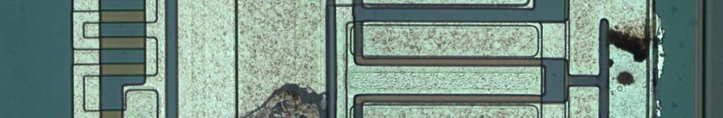


31 Metallization April 2, 2008 Cyrous Rostamzadeh 31

32 Metallization April 2, 2008 Cyrous Rostamzadeh 32
33 Pre-ESD Capacitor Characteristics April 2, 2008 Cyrous Rostamzadeh 33
34 Post-ESD Capacitor Damage DC 20 khz April 2, 2008 Cyrous Rostamzadeh 34


35 Post-ESD Capacitor Damage DC 20 khz April 2, 2008 Cyrous Rostamzadeh 35
36 IC Level ESD Standards DO NOT Test for Soft-Errors (Bit Errors, Upsets, Resets, etc..). They only test if the ICs are Damaged by ESD April 2, 2008 Cyrous Rostamzadeh 36
37 System Level ESD Test Standards applied to operating systems while observing the functionality of the system in addition to observing for any damages. April 2, 2008 Cyrous Rostamzadeh 37
38 System Level Human ESD Model is based on a Discharge of a Human via a piece of Metal. IC Level ESD Model is based on a Discharge from the Skin to Grounded IC April 2, 2008 Cyrous Rostamzadeh 38
39 ESD is Not only a Broadband Event, but an ESD test is a Combination of Different Physical Stresses to a System. April 2, 2008 Cyrous Rostamzadeh 39
40 Electrostatic Problems: Manufacturing. Field Operation. April 2, 2008 Cyrous Rostamzadeh 40
41 ESD Solutions: Manufacturing ESD Control Program Field Failures ESD Robust Design April 2, 2008 Cyrous Rostamzadeh 41
42 Important Distinction ESD Control Program during Manufacturing Does NOT imply ESD Robust Product! April 2, 2008 Cyrous Rostamzadeh 42
43 Hard Failures Junction burnout IC metal burnout Dielectric breakdown Transient Interference Soft Failures Logic Errors System Reset Lost Data Lost program Flow April 2, 2008 Cyrous Rostamzadeh 43
44 Direct Connection Secondary Arcing Electric Field Magnetic Field April 2, 2008 Cyrous Rostamzadeh 44

45 April 2, 2008 Cyrous Rostamzadeh 45

46 April 2, 2008 Cyrous Rostamzadeh 46
47 ESD voltages as high as 30 kv has been observed in automotive environment. ESD is rich in high-frequency (> 3 GHz)! ESD event can create currents in excess of 30 Amps! ESD currents can destroy IC s, PCB traces and other components. ESD can create time-varying Magnetic Field: 25 A/m. ESD can create time-varying Electric Field as high as: 10 kv/m. ESD can create Susceptibility Problems. April 2, 2008 Cyrous Rostamzadeh 47
48 April 2, 2008 Cyrous Rostamzadeh 48
49 ESD phenomena involves Electrical & Thermal Transports on the Scale of nanometers (nm), Circuits and Electronics on the Scale of micrometers (µm), Semiconductor Chip designs range from picoseconds (ps) to microseconds (µs), Electrical Currents of interest range from ma to 10 s of Amperes.Voltages range from Volts to kilovolts (kv). Temperatures vary from room temperature to melting temperatures of 1000 s 0 K. April 2, 2008 Cyrous Rostamzadeh 49
50 Must Quantify the Scale in Space & Time ESD phenomena involves: Microscopic to Macroscopic Scales. ESD is a Thermo-Electric Transport of Material Physics April 2, 2008 Cyrous Rostamzadeh 50

51 April 2, 2008 Cyrous Rostamzadeh 51
52 ESD Physics Electrostatic Field, Pre-ESD E r = Φ Electrostatic Equilibrium, Post-ESD r Φ = 0, E = 0 April 2, 2008 Cyrous Rostamzadeh 52
53 ESD Physics Tribos - Greek for "rubbing" The triboelectric effect is a type of contact electrification in which certain materials become electrically charged after they come into contact with another different material and are then separated. April 2, 2008 Cyrous Rostamzadeh 53
54 Triboelectric Series Positive (+) 1) Air 12) Aluminum 2) Human Skin 13) Paper 3) Asbestos 14) Cotton 4) Glass 15) Wood 5) Mica 16) Steel 6) Human Hair 17) Sealing Wax 7) Nylon 18) Hard Robber 8) Wool 19) Mylar 9) Fur 20) Epoxy Glass 10) Lead 11) Silk 21) Nickel, Copper 22) Brass, Silver 21) Gold, Platinum 22) Polystyrene foam 23) Acrylic 24) Polyester 25) Celluloid 26) Orlon 27) Polyethylene foam 28) Polyethylene 29) PVC (Vinyl) 30) Silicon 31) Teflon Negative (-) April 2, 2008 Cyrous Rostamzadeh 54
55 Typical Electrostatic Voltages Means of Static Generation 10% to 20 % Relative Humidity 65% to 90% Relative Humidity Walking across carpet Walking on Vinyl Floor Worker moving at bench Opening a Vinyl envelope 35 kv 12 kv 6 kv 7 kv 1.5 kv 250 Volts 100 Volts 600 Volts Picking up common Polyethylene bag Sitting on chair padded with Polyurethane foam 20 kv 18 kv 1.2 kv 1.5 kv April 2, 2008 Cyrous Rostamzadeh 55
56 Capacitance ESD Charge Storage Element April 2, 2008 Cyrous Rostamzadeh 56
57 Charge Storage Capacitance C = 1 r 1 4 πε 1 r 2 r 1 r 2 if r 2 C =, ( 111 r) diameter sphere, and for free space, ε = pf, a human has a surface area to1 meter C Human Body pf 12 F / m April 2, 2008 Cyrous Rostamzadeh 57
58 Free-Space Capacitance Human Body Capacitance Earth s Capacitance An object a size of marble 50 pf 700 µf 1 pf In addition, we must consider Parallel Plate Capacitance due to the proximity of an object to the surrounding April 2, 2008 Cyrous Rostamzadeh 58
59 Human Body Model (HBM) Self-Capacitance pf 100 pf 50 pf to infinity 500 Ω to 10 kω April 2, 2008 Cyrous Rostamzadeh 59
60 Human Body Model (HBM) Therefore, the Capacitance of a Human Body is the Combination of Free-Space Capacitance + Parallel-Plate Plate Capacitance and can vary from 50 pf to 250 pf April 2, 2008 Cyrous Rostamzadeh 60
61 Human Body Model (HBM) V HB C R V HB HB HB = 50 = 500 = 0 to 250 pf Ω kv kω April 2, 2008 Cyrous Rostamzadeh 61
62 Human Body Model (HBM) For a Human Body of 100 pf Capacitance, Charged Up to 25 kvolt, Energy Released Per Discharge. Energy = CV 2 Energy 30 mj = (25,000) April 2, 2008 Cyrous Rostamzadeh 62
63 Human Body Model (HBM) The Discharge of a Human (via a small, hand-held metal piece) is basis for the current waveform most often used IEC standard. April 2, 2008 Cyrous Rostamzadeh 63
64 OEM ESD Test Parameters GM3097 (July 2006) Ford ES-XW6T-1A276-AC Chrysler DC ISO (2001) & IEC Standards with some Modifications. Ambient Temperature: 23 +/- 3 o C Relative Humidity 20 to 40% Prefer 20 o C and 30% RH. Contact Rise Time: t r < 1 ns Air Discharge Rise Time: t r < 20 ns. Discharge Networks: 150 pf/2 kω and 330 pf/2 kω April 2, 2008 Cyrous Rostamzadeh 64
65 Events during an ESD Discharge 1.Electrostatic, describing the Charging and Charge Distribution prior to Breakdown. April 2, 2008 Cyrous Rostamzadeh 65
66 Events during an ESD Discharge From Static to GHz Propagation Human ESD: The beginning scenario is a Human holding a small piece of metal (e.g., a key, ring, screwdriver). He has been charged and is approaching a grounded part of a system. April 2, 2008 Cyrous Rostamzadeh 66
67 Events during an ESD Discharge 2. Physics of Sparking, describing the development of the Conductivity in the Arc. April 2, 2008 Cyrous Rostamzadeh 67
68 Events during an ESD Discharge 3. Fast Transient Electromagnetics, during the first phase of the Discharge EM Waves travel on DUT. Local differences and Temporal Changes are Strong. Consequently, the Structure is Electrically Large; Antenna Theory, Shielding and Coupling are the appropriate methods for describing ESD in this phase. Picture this as if a 3 GHz pulses impinges on the DUT. April 2, 2008 Cyrous Rostamzadeh 68
69 Events during an ESD Discharge 4. Slower Currents and Charge Redistribution, after the first phase Current and Voltage derivatives have been reduced by Radiation and Reflection to levels that the dominating frequencies are slow enough, such that the structure can be treated as Electrically Small, A description by equivalent circuit is suitable in this phase of the discharge. April 2, 2008 Cyrous Rostamzadeh 69
70 Fast Transient Phase of ESD Discharge Fast Transient Electromagnetic Phase is the most challenging, but it is the Root-Cause for Most of the Soft-Errors Observed. One should Concentrate on Currents and Voltages present during this phase of the Discharge. April 2, 2008 Cyrous Rostamzadeh 70
71 Reference Event Standard/Model Failure Indication Main Parameters Human Discharging through a small piece of metal IEC Soft-Error (upset, Reset) and Hard Error (Damage) 1-15 kv, ns time 3.75 A/kV Peak Current April 2, 2008 Cyrous Rostamzadeh 71
72 IC Level System Level ESD IC Level HBM (Human Body Model) C = 150 pf System Level HBM C = 150 pf R series = 1500 Ω R series = 330 Ω t rise < 5 ns t rise < 850 ps Voltage usually < 4000 Volts Most test up to 8000 Volts Only damage to the IC System level upset, and damage April 2, 2008 Cyrous Rostamzadeh 72
73 5 kv ESD Discharge ESD Process is associated with Strong Electromagnetic Fields Example: for 5 kv discharge: 18 Amp Peak Current, Rise Time of 850 ps, E = 10 kv/m (10 cm distance) H = 25 A/m (10 cm distance) April 2, 2008 Cyrous Rostamzadeh 73
74 ESD Modeling 1.Human Body Model (HBM) 2.Charged Device Model (CDM) 3.Machine Model (MM) 4.Transmission Line Pulse Model (TLP) April 2, 2008 Cyrous Rostamzadeh 74
75 Events during an ESD Discharge Prior to Discharge an Electrostatic Field exists. There is NO Current flowing (or only very little Current). Therefore, NO relevant Magnetic Field is present. April 2, 2008 Cyrous Rostamzadeh 75
76 Events during an ESD Discharge Once the Distance is sufficiently small a Dielectric Breakdown will occur.the Electric Field Starts Collapsing..It collapses down to about V within 50 ps-5 ns...the collapse time depends on Arc Parameters, Voltage, April 2, 2008 Cyrous Rostamzadeh 76
77 Events during an ESD Discharge A Current starts flowing on the metal part and the DUT. The foremost current front expands with the velocity of light. Within the 800 ps it has reached the arm of the person. Current will expand further on the DUT and the arm. It will experience Reflections and Losses due to Radiation and Resistance complex pattern of Current Density of the DUT and the person. During this phase the person and the DUT act an antenna. This phase is about 10 ns long. The Highest frequency components of the current will be attenuated mainly due to Radiation leading to a smoother current (less high frequency) April 2, 2008 Cyrous Rostamzadeh 77
78 Events during an ESD Discharge As the higher frequency components do not dominate anymore a description as equivalent circuit is possible for a time frame from about 10 ns until the body reaches a new electrostatic equilibrium. The remaining charge may not zero, as the arc might extinguish before this has been reached. If the hand is approaching the DUT further, a second discharge will occur at a lower voltage. This can lead to a sequence of ESDs, each one at a lower voltage, but each one having a faster rise time. April 2, 2008 Cyrous Rostamzadeh 78
79 ESD Mathematical Analysis April 2, 2008 Cyrous Rostamzadeh 79
80 April 2, 2008 Cyrous Rostamzadeh = exp 1 exp 1 ) ( τ τ τ τ τ τ t t t k i t t t k i t i n n n n, exp 1/ = n n k τ τ τ τ = n n k 1/ exp τ τ τ τ τ 4 = 58 ns τ 2 = 1.7 ns I 2 = 10.1 Amp n = 3 τ 3 = 6 ns τ 1 = 1.3 ns I 1 = 21.9 Amp
81 April 2, 2008 Cyrous Rostamzadeh 81
82 April 2, 2008 Cyrous Rostamzadeh 82
83 τ τ HB HB = HBM ESD Time Constant R HB C HB = 1500 Ω 100 pf = 150 ns Similar to Thermal Diffusion Time of many materials used in semiconductor industry April 2, 2008 Cyrous Rostamzadeh 83
84 ESD is a Non-Linear Electro-Thermal Physical Event. Very Difficult to Model Accurately. Simple Linear Model is insightful. April 2, 2008 Cyrous Rostamzadeh 84
85 MM ESD Time Constant τ τ MM MM = = R MM C MM ( 10 to 25) Ω 200 pf = 2 ns Typically 100 times faster than HB time constant, and it is oscillatory. Protection needed is 5 to 10 times lower than required for HB protection. April 2, 2008 Cyrous Rostamzadeh 85
86 ESD Generator Model V Gen = 8 kv April 2, 2008 Cyrous Rostamzadeh 86
 April 2, 2008 Cyrous Rostamzadeh")
87 ESD Generator Model V Gen = 8 kv Current (A) Time (ns) April 2, 2008 Cyrous Rostamzadeh 87
88 ESD HBM Model V HBM = 25 kv April 2, 2008 Cyrous Rostamzadeh 88
 April 2, 2008 Cyrous Rostamzadeh")
89 ESD HBM Model V HBM = 25 kv Current (A) Time (ns) April 2, 2008 Cyrous Rostamzadeh 89
90 PCB Via ESD Protection Interconnect Dilemma April 2, 2008 Cyrous Rostamzadeh 90
91 ESD Protection Interconnect Dilemma Inductance between 2 Connector Pins or Vias L = H loge S R S = Via Separation, in. R = Via Radius, in. H = Via Length, in. L = Inductance, nh. April 2, 2008 Cyrous Rostamzadeh 91
92 ESD Protection Interconnect Dilemma L = H loge S R April 2, 2008 Cyrous Rostamzadeh 92
93 ESD Protection Interconnect Dilemma L via 4 h = 5.08 h ln + 1 d d Typical Value L via = 1 nh h April 2, 2008 Cyrous Rostamzadeh 93
94 ESD Protection Interconnect Dilemma 4h Lvia = 5.08h ln d h = 63 mil d = 16 mil t r X = 1ns L = 1.2 nh L = πl t r = 3.8 Ω + 1 d h April 2, 2008 Cyrous Rostamzadeh 94
95 ESD Protection Interconnect Dilemma 1.41ε C = r TD via D D Pad Typical Value C via = 0.5 pf Clearance Hole April 2, 2008 Cyrous Rostamzadeh 95
96 ESD Protection Interconnect Dilemma Example: Via Pad Diameter = 0.8 mm Via Hole Diameter = 0.3 mm (----> 0.25 mm) Pad h = 1.6 mm, or 63 mil Clearance Hole April 2, 2008 Cyrous Rostamzadeh 96
97 ESD Protection Interconnect Dilemma 1.41 ε C = r TD via D D D2 = Diameter of Clearance hole in GND Plane, in. D1 = Diameter of pad surrounding via, in. Pad T = Thickness of printed circuit board, in C = Capacitance in pf. Typical Value C via = 0.5 pf Clearance Hole Inner Layer GND Planer April 2, 2008 Cyrous Rostamzadeh 97
98 ESD Failure Modes Direct Hit. Pre-ESD Electric Field. Magnetic Field. Electromagnetic Field. Ground Bounce. April 2, 2008 Cyrous Rostamzadeh 98

99 ESD Strategies Avoid Direct Connection from an exposed external point to an Integrated Circuit. E E ~ 30 mj April 2, 2008 Cyrous Rostamzadeh 99
100 ESD Strategies In no case should there be a direct connection from an Integrated Circuit to an exposed external point. April 2, 2008 Cyrous Rostamzadeh 100
101 ESD Strategies Divert or limit the ESD Energy away from Circuit Inputs using Filters or Transient Suppressors. April 2, 2008 Cyrous Rostamzadeh 101
102 ESD Strategies Determine the most vulnerable internal circuits. Most likely to be upset by Electromagnetic Effects Resets, Interrupts and critical control lines. April 2, 2008 Cyrous Rostamzadeh 102
103 ESD Capacitor? 100 pf, 1 nf, 10 nf, 47 nf 100 nf? MLCC 0805, 0603, 0402? 100 Volts, 50 Volts? April 2, 2008 Cyrous Rostamzadeh 103
104 ESD Capacitor Value April 2, 2008 Cyrous Rostamzadeh 104
105 ESD Capacitor Mounting Strategy How far from Connector Pin PCB layer stackup Y-Connection April 2, 2008 Cyrous Rostamzadeh 105
106 ESD Capacitor Failure Mode Voltage Pressure Current Force Dielectric Breakdown April 2, 2008 Cyrous Rostamzadeh 106
107 I HF April 2, 2008 Cyrous Rostamzadeh 107

108 ESD Strategies Solution April 2, 2008 Cyrous Rostamzadeh 108

109 ESD Strategies Solution April 2, 2008 Cyrous Rostamzadeh 109
110 ESD Strategies Solution April 2, 2008 Cyrous Rostamzadeh 110
111 ESD Strategies Use LOW Capacitance Protection Solution High Capacitance Protection --- 6X Longer Delay Time Low Capacitance Protection April 2, 2008 Cyrous Rostamzadeh 111
112 ESD Strategies Solution I HF April 2, 2008 Cyrous Rostamzadeh 112

113 Fast Transient Electromagnetics Frequency ~ 3 GHz ESD Field Collapses to V within 50 ps 5 ns Structure Electrically Large l > λ April 2, 2008 Cyrous Rostamzadeh 113
114 ESD Protection Devices 1. TVS (Transient Voltage Suppressor) 2. MOV Multilayer Zinc Oxide 3. Diode 4. Capacitor 5. Spark Gap 6. Filters 7. Ferrites April 2, 2008 Cyrous Rostamzadeh 114

115 Capacitor Placement April 2, 2008 Cyrous Rostamzadeh 115
116 ESD Protection Interconnect Dilemma 20 nh 20 nh Return April 2, 2008 Cyrous Rostamzadeh 116
117 ESD Protection Interconnect Dilemma 20 nh 20 nh 0 nh Return April 2, 2008 Cyrous Rostamzadeh 117

118 ESD Protection Interconnect Dilemma 20 nh C = 10 nf ESL = 200 ph ESR = 22 mω 20 nh Return 7.94 MHz April 2, 2008 Cyrous Rostamzadeh 118

119 ESD Protection Interconnect Dilemma 20 nh C = 10 nf ESL = 200 ph ESR = 22 mω 0 nh Return MHz April 2, 2008 Cyrous Rostamzadeh 119

120 ESD Protection Interconnect Dilemma 20 nh 20 nh C = 10 nf ESL = 200 ph ESR = 22 mω 0 nh Return MHz April 2, 2008 Cyrous Rostamzadeh 120
121 ESD Protection Interconnect Dilemma Poor Better Best April 2, 2008 Cyrous Rostamzadeh 121
122 April 2, 2008 Cyrous Rostamzadeh 122
123 April 2, 2008 Cyrous Rostamzadeh 123
124 April 2, 2008 Cyrous Rostamzadeh 124
125 April 2, 2008 Cyrous Rostamzadeh 125
126 April 2, 2008 Cyrous Rostamzadeh 126
127 April 2, 2008 Cyrous Rostamzadeh 127
128 ESD Protection Interconnect Dilemma All dimensions are in inches 0603 Capacitor 0603 Skinny Capacitor 0603 Fat end Same via and hole square soldering pad round via pad dia. hole square soldering pad round via pad dia. hole square soldering pad 0402 side 0603 end April 2, 2008 Cyrous Rostamzadeh 128
129 ESD Protection Interconnect Dilemma Hole Diameter in Hole Diameter in Via Length skinny fat end side end side April 2, 2008 Cyrous Rostamzadeh 129
130 ESD Strategies High Density Connector Restricts Optimized Mounting Strategy For ESD Capacitors. April 2, 2008 Cyrous Rostamzadeh 130
131 Prevent ESD Current flow into PCB Ground Structure. This problem can be sneaky! Do NOT assume PCB Ground has a low Impedance! t r = 1nsec (300 MHz +), Z Ground is NOT LOW! Ground BOUNCE CMOS Latch-up. In reality ESD does NOT cause damage; it just sets things up so the power supply can destroy the part! April 2, 2008 Cyrous Rostamzadeh 131
132 Due to ESD Transient Nature: Fast (edge rate ~< 1 nsec) Digital Circuits are Highly Susceptible! Slow Analog Circuits are Immune! NOTE: This is NOT a Direct ESD Discharge! It is due to Electromagnetic Fields and Pre-ESD Electric Field. April 2, 2008 Cyrous Rostamzadeh 132
133 Minimize interconnect Inductance. Use lowest value Capacitors to prevent degradation of High-Speed signals. April 2, 2008 Cyrous Rostamzadeh 133
134 Spark Gap Protection Mechanism April 2, 2008 Cyrous Rostamzadeh 134
135 Spark Gap April 2, 2008 Cyrous Rostamzadeh 135
136 Topler Law "Gas Discharge Process": I a ( t) = = Topler Surface Process; d = arc length I a gas T surf M ( t) = U a U a arc T ( t) d 0 ( ξ ) dζ Constant 8 10 arc M ( t) d Spark Gap Physics t t 0 I ( ξ ) dζ = Surface Process Constant I gas surf -4 Vs/m at Normal Pressure Vs/m April 2, 2008 Cyrous Rostamzadeh 136
137 PSPICE Model for Spark Gap < 0.1 uh R HB = 330 Ω I arc (t) I surf (t) I gas (t) C HB = 150 pf C gap Spark Gap April 2, 2008 Cyrous Rostamzadeh 137

138 Spark Gap April 2, 2008 Cyrous Rostamzadeh 138

139 Spark Gap April 2, 2008 Cyrous Rostamzadeh 139


140 Connector Area ESD Capacitors April 2, 2008 Cyrous Rostamzadeh 140

141 Connector Area ESD Capacitors April 2, 2008 Cyrous Rostamzadeh 141

142 High Frequency Design Practice ESD ESD April 2, 2008 Cyrous Rostamzadeh 142
143 ESD Exteremely Fast Transient ESD Has Several Failure Modes Several Design Tactics Several Strategic Concepts ESD Circuit Protection ESD Grounds ESD Shuelding April 2, 2008 Cyrous Rostamzadeh 143
144 Thank you for your Participation. April 2, 2008 Cyrous Rostamzadeh 144
Mounting Type Contact form Quick-connect Screw terminals PCB terminals. E-bracket SPST-NO G7L-1A-T G7L-1A-B
 A High-capacity, High-dielectricstrength Relay Compatible with Momentary Voltage Drops No contact chattering for momentary voltage drops up to 0% of rated voltage. Wide-range AC-activated coil that handles
10 A at 100 to 240 VAC. G3NE-220T-US (20 A at 75 to 264 VAC) 5 A at 100 to 240 VAC
 5 A at 100 to 240 VAC") Solid State Relays G3NE Compact, Low-cost, SSR Switching 5to20 A Wide load voltage range: 75 to 264 VAC. Dedicated, compact aluminum PCB and power elements used. Built-in varistor effectively absorbs external
Solid State Relays G3NE Compact, Low-cost, SSR Switching 5to20 A Wide load voltage range: 75 to 264 VAC. Dedicated, compact aluminum PCB and power elements used. Built-in varistor effectively absorbs external
SerDes and its Role in Future Designs
 SerDes and its Role in Future Designs Rod Strange Business Development Manager rod@teraspeed.com New Albany, Indiana Toll Free: +1-844-483-7773 (4TERASPD) USA & Canada Tel: +1-812-981-8398 inquire@teraspeed.com
Engineering Design Assurance Test Report ( S )
") TEST EQUIPMENT LIST: AC Source : Chroma programmable AC source Model 61504 Power Analyzer : Chroma Power Analyzer Model 6630 Load : Chroma Electronic DC Load 63103 Oscilloscope : Lecroy wave surfer 424
TEST EQUIPMENT LIST: AC Source : Chroma programmable AC source Model 61504 Power Analyzer : Chroma Power Analyzer Model 6630 Load : Chroma Electronic DC Load 63103 Oscilloscope : Lecroy wave surfer 424
Using HARDSIL to minimize the impact of extreme temperature on CMOS integrated circuits. VORAGO TECHNOLOGIES Austin, Texas
 Using HARDSIL to minimize the impact of extreme temperature on CMOS integrated circuits VORAGO TECHNOLOGIES Austin, Texas Introduction There is a growing trend to increase the sophistication of electronics
Type Contact form Plug-in/solder Plug-in/solder PCB terminals Upper-mounting terminals terminals with plug-in/solder
 A Miniature Power Relay Equipped with arc barrier. Dielectric strength: 2,000 V. Built-in diode models added to the LY Series. Single-pole and double-pole models are applicable to operating coils with
Engineering Design Assurance Test Report ( S ) MODEL: SPS-070P V 12 Amax 60 Wmax
 MODEL: SPS-070P V 12 Amax 60 Wmax") TEST EQUIPMENT LIST: AC Source : Chroma programmable AC source Model 61504 Power Analyzer : Chroma Power Analyzer Model 6630 Load : Chroma Electronic DC Load 63103 Oscilloscope : Lecroy wave surfer 424
TEST EQUIPMENT LIST: AC Source : Chroma programmable AC source Model 61504 Power Analyzer : Chroma Power Analyzer Model 6630 Load : Chroma Electronic DC Load 63103 Oscilloscope : Lecroy wave surfer 424
Power Relay RCE. Ordering Information. A High-capacity, High-dielectric-strength Relay Compatible with Momentary Voltage Drops
 Power Relay A High-capacity, High-dielectric-strength Relay Compatible with Momentary Voltage Drops No contact chattering for momentary voltage drops up to 0% of rated voltage. Wide-range AC-activated
Engineering Design Assurance Test Report ( S ) MODEL: SPS-350P V 14.7 Amax 353 Wmax TEST EQUIPMENT LIST:
 MODEL: SPS-350P V 14.7 Amax 353 Wmax TEST EQUIPMENT LIST:") TEST EQUIPMENT LIST: INPUT FUNCTION TEST AC Source : Chroma programmable AC source Model 61504 Power Analyzer : Chroma Power Analyzer Model 6630 Load : Chroma Electronic DC Load 63103 Oscilloscope : Lecroy
TEST EQUIPMENT LIST: INPUT FUNCTION TEST AC Source : Chroma programmable AC source Model 61504 Power Analyzer : Chroma Power Analyzer Model 6630 Load : Chroma Electronic DC Load 63103 Oscilloscope : Lecroy
Engineering Design Assurance Test Report ( S ) MODEL: SPS--230P V 9.6 Amax 230 Wmax TEST EQUIPMENT LIST:
 MODEL: SPS--230P V 9.6 Amax 230 Wmax TEST EQUIPMENT LIST:") TEST EQUIPMENT LIST: INPUT FUNCTION TEST AC Source : Chroma programmable AC source Model 61504 Power Analyzer : Chroma Power Analyzer Model 6630 Load : Chroma Electronic DC Load 63103 Oscilloscope : Lecroy
TEST EQUIPMENT LIST: INPUT FUNCTION TEST AC Source : Chroma programmable AC source Model 61504 Power Analyzer : Chroma Power Analyzer Model 6630 Load : Chroma Electronic DC Load 63103 Oscilloscope : Lecroy
General-Use Auto-Tuning HPX-T Series
 General-Use Auto-Tuning HPX-T Series Built-in Hyper-tuning automatically adjusts scanning characteristics. Adjustment steps, results and scanning conditions are digitally displayed by LED. Digital display
Installation and Maintenance Manual
 Freestanding Gas Stove MODEL: PGS2005 GPEBB20R GPEBW20R Installation and Maintenance Manual Warning Maintenance products should be carried out by professional and technical personnel with relevant qualification,
Plug-in/solder terminals with LED indicator
 General-purpose Relay LY Electromechanical Relays A Miniature Power Relay Equipped with arc barrier. Dielectric strength: 2,000 V. Built-in diode models added to the LY Series. Single-pole and double-pole
Total solder points: 129 Difficulty level: beginner advanced LIQUID LEVEL CONTROLLER K2639 ILLUSTRATED ASSEMBLY MANUAL
 Total solder points: 129 Difficulty level: beginner 1 2 3 4 5 advanced LIQUID LEVEL CONTROLLER K2639 Forgotten to turn off the tap, leaking washing machines,... Prevention is better than cure. So use this
Product Specification
 HDBNC-BH1 Jack, Right Angle Orientation, PCB Terminated HDBNC-CA Plug, Straight Orientation, Cable Terminated Other configurations available for: Vertical cable-to-board applications Through-hole, edge
Introduction 2. Other Applicable Documents 2. Scope of Delivery 3. Attaching the Snap-on Ferrite Suppressor 4
 H-206.F2 6-Axis Precision Alignment System Contents Introduction 2 Other Applicable Documents 2 Scope of Delivery 3 Attaching the Snap-on Ferrite Suppressor 4 Connecting the Hexapod to the C-887 with the
General-purpose Relay
 General-purpose Relay A Miniature Power Relay Equipped with arc barrier. Withstand : 2,000 V. RC+Y LR Ordering Information Open Relays Type Contact form Plug-in/solder terminals Plug-in/solder terminals
Test Report: HB
 Test Report: HB-100-48 100W Single Switching ower Supply DESIGN VERIFY TEST Function Test Input Function Test rotection Function Test Other Test Component Stress Test SAFETY & E.M.C. TEST Safety Test E.M.C.
Test Report: HEP
 Test Report: HEP-600-24 600W Single Output Switching Power Supply DESIGN VERIFY TEST Output Function Test Input Function Test Protection Function Test Control Function Test Component Stress Test SAFETY
Reliability Data LUXEON K2. Introduction. Index. Reliability Datasheet RD06
 Reliability Datasheet RD06 LUXEON K2 Reliability Data Introduction This reliability datasheet summarizes the reliability performance of LUXEON K2. Overall product reliability depends on the customer's
FILTRONIC AB EXTRACTION ARMS AND NOZZLES FOR A BETTER WORKBENCH ENVIRONMENT
 FILTRONIC AB EXTRACTION ARMS AND NOZZLES FOR A BETTER WORKBENCH ENVIRONMENT FILTRONIC AB Box 2284, SE-531 02 LIDKÖPING Tel +46 510-208 10, Fax +46 510-201 40 e-mail: office@filtronic.se www.filtronic.se
Reliability of Conformal Coated Surface Mount Parts
 Reliability of Conformal Coated Surface Mount Parts Deng Y. Chen and Dr. Michael Osterman Center for Advanced Life Cycle Engineering (CALCE) University of Maryland, College Park, MD 20742 January-4-17
DJET. Pushbuttons. toggle switch 6,35 mm dia. recommended accessories: - mounting dimension. technical drawing. circuit drawing
 Pushbuttons toggle switch 6,35 mm dia. toggle switch 6,35 mm dia. no. of poles material of contacts Switching position connection method colour part no. 2 silver 2 (maintained chromiumplated 02.17312.21
NK Multi-stage submersible pumps
 NK Multi-stage submersible pumps PERFORMANCE RANGE Flow rate up to 120 l/min (7.2 m³/h) Head up to 10 m APPLICATION LIMITS Maximum liquid temperature +40 C Maximum sand content 0 g/m³ 20 m maximum immersion
Test Report. 240W Single Output Switching Power Supply DESIGN VERIFY TEST
 Test Report 240W Single Switching ower Supply DESIGN VERIFY TEST Function Test Input Function Test rotection Function Test Other Test Component Stress Test SAFETY & E.M.C. TEST Safety Test E.M.C. Test
Type CGS High-Cap Screw Terminal Aluminum Electrolytic Capacitor
 High CV, Screw Terminal Capacitors Specifications Capacitance Range: Voltage Range: Capacitance Tolerance: Operating Temperature: Ripple Current Multipliers: Type CGS screw terminal, aluminum electrolytic
Safety insulation transformers for SmartPower controller family
 Design and Manufacture of inductive components and ferrites for industrial electronics automotive electronics lighting techonology consumer goods industry telecommunications / entertainmentelectronics
FIBER OPTIC CLOSURES
 FIBER OPTIC CLOSURES In-line type and dome type - series CLS-I, CLS- IF2X, CLS-D, CLS-DF2X144 and CLS-DF2X240 PACIFIC INTERCONNECTIONS - connecting the world with fiber optics IN-LINE TYPE FIBER OPTIC
General Purpose High Power PCB Relays
 T9 Series Two-pole 3A PCB or Panel Mount Relay n A, form A (NO) and form C (CO) switching capability n Designed to control compressor loads to 3.5 tons, LRA / 5.3FLA n Meets requirements of UL 58 and UL
Test Report: GSM40A18
 Test Report: GSM40A18 40W AC DC Single Output Medical Type DESIGN VERIFY TEST Output Function Test Input Function Test rotection Function Test Control Function Test Component Stress Test SAFETY & E.M.C.
Test Report: EPP
 Test Report: E 150 24 150W Single Output with FC Function DESIGN VERIFY TEST Output Function Test Input Function Test rotection Function Test Control Function Test Component Stress Test SAFETY & E.M.C.
Test Report: EPP
 Test Report: E 100 24 100W Single Output with FC Function DESIGN VERIFY TEST Output Function Test Input Function Test rotection Function Test Control Function Test Component Stress Test SAFETY & E.M.C.
EA-12 Coupled Harmonic Oscillators
 Introduction EA-12 Coupled Harmonic Oscillators Owing to its very low friction, an Air Track provides an ideal vehicle for the study of Simple Harmonic Motion (SHM). A simple oscillator assembles with
Emergency Stop Devices
 New! Selection and Application of.. 278 Emergency Stop Rope Pull Switches........... 279 New! Emergency Stop Push Buttons............... 293 Banner Engineering Corp. Minneapolis, MN U.S.A. bannerengineering.com
Load-following capabilities of Nuclear Power Plants. Erik Nonbøl
 Load-following capabilities of Nuclear Power Plants Erik Nonbøl Outline Why load-following Modes of power operation BWR technique for load-following PWR technique for load-following Effects on components
Test Report: IRM-05-24
 Test Report: IRM-05-24 5W Single Output Encapsulated Type DESIGN VERIFY TEST Output Function Test Input Function Test rotection Function Test Control Function Test Component Stress Test SAFETY & E.M.C.
Test Report: EDR-75-12
 Test Report: EDR-75-12 75W Single Output Industrial DIN RAIL DESIGN VERIFY TEST Output Function Test Input Function Test rotection Function Test Component Stress Test SAFETY & E.M.C. TEST Safety Test E.M.C.
Supplementary protector S 200 MR for ring-tongue applications acc. to UL 1077
 Electrical installations in buildings for ring-tongue applications acc. to UL 1077 S 200 MR is a high-performance supplementary protector with ring cable lug connections conforming to UL, CSA, and IEC
ULTRA-LIGHTWEIGHT RUGGED GALAXY SERIES
 ULTRA-LIGHTWEIGHT RUGGED GALAXY SERIES UPS MIL-SPEC COMPLIANT 1-5 KVA 1-5 U UNIVERSAL 120/240 VAC PFC INPUT SNMP COMMUNICATIONS WHEN EVERY POUND COUNTS! APPLICATIONS Shelters Tactical Systems Shipboard
Test Report: IRM-10-12
 Test Report: IRM-10-12 10W Single Output Encapsulated Type DESIGN VERIFY TEST Output Function Test Input Function Test rotection Function Test Control Function Test Component Stress Test SAFETY & E.M.C.
Table of Contents. DS107 LUXEON Rebel PLUS Product Datasheet Lumileds Holding B.V. All rights reserved.
 Illumination LUXEON Rebel PLUS The original high power LED LUXEON Rebel PLUS is designed with the highest possible efficacy and light output from an industry standard 4530 package with a 2.5mm 2 dome.
DETECTING CRACKS UNDER BUSHINGS WITH ROTATIONAL REMOTE-FIELD EDDY CURRENT PROBES
 DETECTING CRACKS UNDER BUSHINGS WITH ROTATIONAL REMOTE-FIELD EDDY CURRENT PROBES Yushi Sun, Tianhe Ouyang, Jie Long 2501 N. Loop Drive, Ames, IA 50010 Jeff Thompson, Jeff Kollgaard Boeing Commercial Airplanes
Reliable high-power LED that gives you the design flexibility and performance you need
 General Illumination LUXEON Rebel Reliable high-power LED that gives you the design flexibility and performance you need LUXEON Rebel LEDs deliver optimized combinations of light quality and light output
212iLM Mullion (ILLUMINATED WEATHER RESISTANT) Keypad
 Keypad") International Electronics, Inc. 427 Turnpike Street Canton, Massachusetts 02021 212iLM Mullion (ILLUMINATED WEATHER RESISTANT) Keypad Stand Alone Keypad-Installation Manual Features: 120 User Capability
International Electronics, Inc. 427 Turnpike Street Canton, Massachusetts 02021 212iLM Mullion (ILLUMINATED WEATHER RESISTANT) Keypad Stand Alone Keypad-Installation Manual Features: 120 User Capability
Test Report: IRM-05-05
 Test Report: IRM-05-05 5W Single Output Encapsulated Type DESIGN VERIFY TEST Output Function Test Input Function Test rotection Function Test Control Function Test Component Stress Test SAFETY & E.M.C.
Model Number Structure
 Solid State Relays Refer to Safety Precautions for All Solid State Relays. Extremely Thin Relays Integrated with Heat Sinks Downsizing achieved through optimum design of heat sink. Mounting possible via
Smallest Connector with Removable Contacts
 1 Ultra-Miniature 8STA Size 01 Connectors Smallest Connector with Removable Contacts Ultra compact design and very lightweight connector dedicated to the harshest of motorsport environments. Innovative
Pelican AMR Gateway User Guide
 Pelican AMR Gateway User Guide Document Reference: 8194 June 2016 Version: 2 Version Date Author Changes Number 1 Feb 2014 Bettina Rubek-Slater 2 Jun 2016 Sam Smith Branding updated API section updated
Test Report: IRM-20-24
 Test Report: IRM-20-24 20W Single Output Encapsulated Type DESIGN VERIFY TEST Output Function Test Input Function Test rotection Function Test Control Function Test Component Stress Test SAFETY & E.M.C.
SPECIAL-TWEEZERS FOR THE SMD-TECHNIQUE
 SPECIAL-TWEEZERS FOR THE SMD-TECHNIQUE high precision tweezers from special steel stainless matt finish anti magnetic acid resisting - alternative with ESD coating (-13) - Finish Weight 5-049 110 4 3 /8''
TRUMPF TRUMATIC L 3050
 TRUMPF TRUMATIC L 3050 CNC laser cutting machine Manufacturer TRUMPF Model TRUMATIC L 3050 Year of manufacture 2004 Control Machine number Travels SIEMENS SINUMERIK 840 D A0230A0580 X 3.000 mm / Y 1.500
Load-following capabilities of nuclear power plants
 Downloaded from orbit.dtu.dk on: Sep 18, 2018 Load-following capabilities of nuclear power plants Nonbøl, Erik Publication date: 2013 Link back to DTU Orbit Citation (APA): Nonbøl, E. (2013). Load-following
Driving STM32 to success STM32 services for sophisticated embedded applications
 Building a safe and secure embedded world Driving STM32 to success STM32 services for sophisticated embedded applications > STM32 Services HITEX: the stm32 experts Questions about STM32? Ask us! STM32
Parts. Section 7. Using the Illustrated Parts List. Parts 7-1. The parts lists provided in this section are organized into the following columns:
 7-1 Section 7 Using the Illustrated List The parts lists provided in this section are organized into the following columns: Item Identifies illustrated parts that are available from Nordson Corporation.
Test Report: EPS 15 12
 Test Report: ES 15 12 15W Single Output Switching ower Supply DESIGN VERIFY TEST Output Function Test Input Function Test rotection Function Test Control Function Test Component Stress Test SAFETY & E.M.C.
Multi-rate 10-Gigabit DWDM 40km XFP Transceiver with Digital Diagnostics
 Multi-rate 10-Gigabit DWDM 40km XFP Transceiver with Digital Diagnostics TXD3XGGIx000xxG Pb Product Description The TXD3XGGIx000xxG DWDM XFP multi-rate fiber optic transceivers with digital diagnostics
Test Report: APC
 Test Report: AC-25-500 25W Single Output Switching ower Supply DESIGN VERIFY TEST Output Function Test Input Function Test rotection Function Test Component Stress Test SAFETY & E.M.C. TEST Safety Test
HardSID Uno / UPlay user s guide HardSID Uno HardSID UPlay
 HardSID Uno / UPlay user s guide HardSID Uno HardSID UPlay HardSID Uno / UPlay user s guide 2010 Hard Software, Hungary 1 Safety information... 4 Introduction:... 5 Package contents... 5 System requirements...
B 270 Superwite D Requirements deviating from these specifications must be defined in writing in a customer agreement.
 B 270 uperwite B 270 uperwite D 0092 B 270 uperwite is a clear high transmission crown glass (modified soda-lime glass) available in form of sheets, optical rods, profiled rods, strips and chain moulded
Stratomaster Maxi Single
 Stratomaster Maxi Single ASI-3 Airspeed indicator (ASI) with automatic flight log The ASI-3 airspeed indicator is a 3.5 instrument that provides a wide range airspeed indication in both digital and analog
HOSE ASSEMBLY CLEANLINESS
 November 18, 2002 HOSE ASSEMBLY CLEANLINESS Preface Hydraulic system cleanliness is a term used to describe the level of solid and liquid contamination found in hydraulic systems. Contamination may be
Modeling Approach for Electromagnetic Simulation of Anechoic Chambers
 Bitte decken Sie die schraffierte Fläche mit einem Bild ab. Please cover the shaded area with a picture. (24,4 x 11,0 cm) Modeling Approach for Electromagnetic Simulation of Anechoic Chambers Ralf Kakerow,
HEATER POWER CONTROLLER
 HEATER POWER CONTROLLER /04 Rev 0 - - ii PROCON MODEL HPC TABLE OF CONTENTS DESCRIPTION... MANUAL REVISIONS... 5 WARRANTY... 5 SPECIFICATIONS... 6 DRAWINGS PHYSICAL DIMENSIONS 44-090095-0-00... 7 PANEL
Feasibility of Battery Backup for Flight Recorders
 KEYWORDS Aviation Cockpit Voice Recorder Flight Data Recorder Battery backup Feasibility of Battery Backup for Flight Recorders Duncan W. Schofield AlliedSignal Inc., Air Transport & Regional Avionics
FACILITATION (FAL) DIVISION TWELFTH SESSION. Cairo, Egypt, 22 March to 2 April 2004
 DIVISION TWELFTH SESSION. Cairo, Egypt, 22 March to 2 April 2004") 19/2/04 English only FACILITATION (FAL) DIVISION TWELFTH SESSION Cairo, Egypt, 22 March to 2 April 2004 Agenda Item 2: Facilitation and security of travel documents and border control formalities 2.5:
19/2/04 English only FACILITATION (FAL) DIVISION TWELFTH SESSION Cairo, Egypt, 22 March to 2 April 2004 Agenda Item 2: Facilitation and security of travel documents and border control formalities 2.5:
6.1. Power Supplies. Contents. PSG Series. General-Purpose and Sensor Power Supplies. Features, Benefits and Functions. Product Description
 .1 PSG Series Contents Description PSG Series Catalog Number Selection................ Technical Data and Specifications.......... Power Derating Curves.................. Dimensions...........................
SOUDATHERM SFI 600P. Revision date: 19/06/2015 Page 1 of 6
 Revision date: 19/06/2015 Page 1 of 6 Technical data: Basis Polyurethane Foam Consistency Liquid Curing system Moisture curing Skin formation (20 C and 60% R.H.)* 8 min Curing time (20 C and 60% R.H.)*
SPEDESTER Series QUICK REFERENCE GUIDE
 Spedester series Digital DC Drives come with an extensive range of standard software blocks, it can take control of the most demanding motion control tasks. Designed for industrial applications, Spedester
MX Series MX40-7XXX Series MX40-6XXX Series. Selection Guide. Applications. DuraDrive Series Actuator (Includes Accessories)
") MX40-6043 Series MX40-7XXX Series MX40-6XXX Series Selection Guide Applications DuraDrive Direct Coupled Actuators are designed to accept two-position, floating, or proportional control from a DDC system
MX40-6043 Series MX40-7XXX Series MX40-6XXX Series Selection Guide Applications DuraDrive Direct Coupled Actuators are designed to accept two-position, floating, or proportional control from a DDC system
HAND TOOLS. Combination Wrenches 120/1. Combination Wrench Sets 120/1CB. Adjustable Wrenches 250/1. Hexagon Wrenches 230/3SL.
 Combination Wrenches 120/1 Unior wrenches are made of quality chrome vanadium steel. They are available in two lines: chrome plated with polished heads or chromium plated only. Wrenches are functional
Hammer, Discus, Shot Put, Javelin
 Hammer, Discus, Shot Put, Javelin Competition Aluminium Discus And Hammer Cage 7/10 M Order No. 30290 Order No. 30290 D (Double Net) Order No. 30290 DS (Dismantle to fit a 20 container) Competition aluminium
Distinctive Characteristics
 Distinctive Characteristics Base of heat resistant resin meets ULV-0 flammability rating. Maximized voltage capability of V allows use in medium source applications and increases operating life. Award-winning
SECTION I-1. Type: 1812-AC. Fuel: Air-Gas.
 RADIANT LINE BURNER. SECTION I-1. Type: 1812-AC. Manufactured from a heat resisting cast alloy with a ceramic front face, this radiant burner type is ideally suited for use in Infrared Heating production
Total energy variometer 68-PVF-1. Description and installation
 Total energy variometer 68-PVF-1 Description and installation Description The variometer is based on the aneroid principle. But deviating from the conventionally used lever system with gear segment, this
Multi/many core in Avionics Systems
 Multi/many core in Avionics Systems 4th TORRENTS Workshop December, 13 th 2013 Presented by Jean-Claude LAPERCHE - AIRBUS Agenda Introduction Processors Evolution/Market Aircraft needs Multi/Many-core
 Distributed by: www.jameco.com 1-800-831-4242 The content and copyrights of the attached material are the property of its owner. 480W Single Output Industrial DIN RAIL with FC Function SECIFICATION MODEL
ATHLETICS High Jump & Pole Vault
 ATHLETICS High Jump & Pole Vault Aluminium Crossbar Placer ECO The aluminium crossbar placer ECO is made from aluminium. It consists of a two placers for 3 and 5 m. Therefore, the crossbar can be replaced
CASM electric cylinders The modular electric cylinder system
 CASM electric cylinders The modular electric cylinder system CASM electric cylinders are ideally suited to performing fast and powerful linear movements. Unlike pneumatic or hydraulic cylinders, CASM electric
for for HotValley TM TM
 for for HotValley INTRODUCTION The HotValley system holds self-regulating ice melt cable in place on roof valleys and flashings. It can be used in roof valleys (see above), on flashings next to vertical
Parts. Section 7. Using the Illustrated Parts List. Parts 7-1. The parts lists provided in this section are organized into the following columns:
 7-1 Section 7 Using the Illustrated List The parts lists provided in this section are organized into the following columns: Item Identifies illustrated parts that are available from Nordson Corporation.
SB3T. Roll-InBuddy + Tilt. Dignity + Ease + Comfort. Product features include:
 SB3T Roll-InBuddy + Tilt The revolutionary tilt option incorporated into the Roll-InBuddy Tilt allows for pressure release as well as a more thorough bathing experience for the user and easier reach for
USER MANUAL. Tavor 8-T Active Ceiling Speaker MODEL: P/N: Rev 4
 KRAMER ELECTRONICS LTD. USER MANUAL MODEL: Tavor 8-T Active Ceiling Speaker P/N: 2900-300343 Rev 4 Contents 1 Introduction 1 2 Getting Started 2 2.1 Achieving the Best Performance 2 2.2 Safety Instructions
20W Single Output Industrial DIN Rail Power Supply MODEL:MDR OUTPUT FUNCTION TEST NO TEST ITEM SPECICATION TEST CONDITION RESULT VERDICT
 20W Single Outut Industrial DIN Rail Power Suly MODEL:MDR-20-12 OUTPUT FUNCTION TEST 1 RIPPLE & NOISE V1: 120 mv- (Max ) I/P: 230VAC V1: 19 mv- (Max ) 2 OUTPUT VOLTAGE CH1: 10.8 V~ 13.2 V 10.21 V~ 13.85
630 to 1800 A. Functions. Conformity to standards. General characteristics. Fuse combination switches SIDERMAT combination.
 SIDERMAT combination 630 to 1800 A sdmat_048_a_1_cat SIDERMAT combination are manually operated tri- or tetrapolar fuse disconnecting switches which can be triggered remotely. They provide breaking and
2843 Centerport Circle, Pompano Beach, Florida USA Toll Free: Direct: Fax:
 STC1110-RF ULTRAGRIP, 8.2 MHZ RF, ONE PIECE LANYARD AND TAG The UltraGrip is a one piece tag with a 5.90 (150 MM) lanyard combination that saves time during application and removal. It s compatible with
RTA flexible conduits
 [ PROTETION OF LES ] Products and systems RT flexible conduits For each application and environmental stress there is a corresponding polyamide, PV or metal-plastic flexible conduit solution, ideal for
Jameco SKU Number:
 Jameco SKU Number: 2105560 SECIFICATION MODEL OUTUT INUT ROTECTION ENVIRONMENT SAFETY & EMC (Note 4) OTHERS NOTE DC VOLTAGE RATED CURRENT CURRENT RANGE RATED OWER LINE REGULATION LOAD REGULATION HOLD U
Pyrolytic Graphite Sheet
 Pyrolytic The Future of Thermal Management You are the visionaries. The engineers. The designers. The architects of the next dimension. We are the makers of your building blocks. Panasonic manufactures
LUXEON Rebel ES. Energy Saving
 LUXEON Rebel ES High efficiency for maximum energy savings Technical Datasheet DS61 LUXEON Rebel ES Energy Saving Hg Introduction LUXEON Rebel ES provides the quality light output and benefits of the world
LUXEON Rebel PLUS Freedom From Binning
 LUXEON Rebel PLUS Freedom From Binning Hot Tested Superior Quality of Light Technical Datasheet DS107 LUXEON Rebel PLUS Freedom From Binning Introduction LUXEON Rebel PLUS LEDs from Philips Lumileds are
Therme storage water heater. Table of contents. Symbols used. Symbols used Symbol indicates a possible hazard. Installation instructions
 Therme storage water heater Table of contents Symbols used... 8 Installation instructions Water supply... 9 Choice of location... 9 Installation of the Therme... 9 Fitting the draining and venting valve...
ITB-04015TIK17. DRC BID FORM Invitation to Bid No: ITB-04015TIK17. Quantity required Pcs Pcs
 DRC BID FORM Invitation to Bid No: ITB-04015TIK17 ANNEX A Lot 1: Core Relief Items DRC to complete # Item Required Specification 1 Gas Cooker 2 kg gas cylinder filled and cooking burner attached required
a Nexans company Catalogue 2009
 a Nexans company Catalogue 2009 EUROMOLD COMPANY PRESENTATION EUROMOLD Euromold is the leading European specialised designer, manufacturer and distributor of prefabricated cable accessories for medium
brand keyless security locks for Locker and Furniture
 brand keyless security locks for Locker and Furniture Combination Locks RL-9041 Users can set up their own combinations: 10,000 combinations Material: zinc alloy lock housing Vertical and horizontal types
Manual for External Batch/Screw Counter (NEX-PLC) for Screw Feeder FM-36
 for Screw Feeder FM-36") Manual for External Batch/Screw Counter (NEX-PLC) for Screw Feeder FM-36 1.Summary This counter can interface with Screw Feeder FM-36 by setting the number of batches/screws, to be fed, directly into this
Manual for External Batch/Screw Counter (NEX-PLC) for Screw Feeder FM-36 1.Summary This counter can interface with Screw Feeder FM-36 by setting the number of batches/screws, to be fed, directly into this
AWNING CONTROL KIT 98GCK-33B
 AWNING CONTROL KIT 98GCK-33B REV.07282015 RV AWNING PRODUCTS 1361 CALLE AVANZADO, SAN CLEMENTE, CA 92673 (800) 382-8442 FAX (949)276-5500 www.girardrv.com AC MOTOR CONTROL MODULE GC274B INSTALLATION and
SIN GLE BOND HOSE CLAMPS
 Sec. 24 YOKE ENDS & HOSE CLAMPS Zinc Fin ished Drop Forged Yoke Ends Ad just able Auveco T Dimensions In Inches Unit Part No. Tap Size A B C D E F G H K Pkg. 10737 1/4-28 2 7/16 7/16 1-1/4 9/32 5/8 1/4
AISI 316L PERFORMANCE RANGE INSTALLATION AND USE
 CP-ST Stainless steel centrifugal pumps CP-ST4 Pump body: stainless steel AISI 304 Impeller: stainless steel AISI 304 Shaft: stainless steel AISI 431 CP-ST6 Pump body: stainless steel AISI 316L Impeller:
Digimatic Holtest SERIES 468 Three-Point Internal Micrometers
 Digimatic Holtest SERIES 468 Three-Point Internal Micrometers FEATURES Three-point internal micrometer with a digital LD display (text height = 7.4 mm). Titanium-coated measuring surfaces. Built-in memory