Crystal River Airport Master Plan Update
|
|
|
- Agnes Lloyd
- 5 years ago
- Views:
Transcription


1 Crystal River Airport Master Plan Update Final Report November 2017 Prepared for: Citrus County, FL Prepared by: URS Corporation and American Infrastructure Development, Inc.
2
3 Crystal River Airport Master Plan Update Final Report Prepared for: Citrus County, FL Prepared by: URS Corporation and American Infrastructure Development, Inc. November 2017
4
5 Table of Contents TABLE OF CONTENTS Section Page SECTION 1 AIRPORT INVENTORY UPDATE Introduction Master Plan Goals and Objectives Previous Planning Documents Airport Location, Role and Management Airport Setting and Location Airport Administration CGC s Role in National Air Transportation System Airfield Pavements and Lighting Runways and Taxiways Lighting Signage and Marking Takeoff and Landing Aids Aprons and Aircraft Parking Navigational Aids and Airspace Approach Aids Procedures Airspace Obstructions to Airspace On-Airport Buildings and Structures Airport Access and Parking Airport Security Fencing Weather Reporting and Wind Coverage General Aviation Services Crystal Aero Group Aviation Fuel Utilities Electric Power Water Sewer Airport Facilities and Local Development Plans Local Transportation Planning Planned Development Projects SECTION 2 FORECASTS Introduction Historical Aviation Activity Historical Annual Aircraft Operations Historical Annual Instrument Operations Historical Annual Based Aircraft Forecast of Aviation Demand Forecast of Annual Aircraft Operations Forecast of Based Aircraft Fleet Mix Forecast Forecast of Peaking Characteristics i Crystal River Airport Master Plan Update
6 Table of Contents 2.5 Summary of Forecasts SECTION 3 FACILITY REQUIREMENTS Introduction Airfield Capacity Analysis Meteorological Conditions Aircraft Fleet Mix Runway Use Touch-and-Go Operations Percentage Arrivals Exit Taxiway Locations Handbook Methodology Capacities Airfield Facility Requirements Design Aircraft Runway Design Code and Airport Reference Code Airfield Design Standards Number of Runways Runway Length Requirements Runway Width Runway Pavement Strength Runway Shoulders Blast Pad Geometric Requirements Taxiways Holding Bays Pavement Markings Navigational Aids Airfield Lighting Terminal Area Facilities Airport Access Property Acquisition Summary of Facility Requirements Airfield Terminal Area Facilities SECTION 4 RPZ ALTERNATIVES Introduction Existing Land Uses in the RPZs Proposed Land Use Changes in the RPZ Need for Proposed Roadway Improvements Sponsor Control of RPZ Land Federal, State and Local Transportation Agencies Identification of RPZ Alternatives Cost Estimates Practicability Assessment and Identification of Preferred Alternative Operational Impacts Compliance with FAA Land Use Guidance Cost Implications Constructability Other Factors ii Crystal River Airport Master Plan Update
7 Table of Contents SECTION 5 ALTERNATIVES Introduction Airfield Alternatives Runways Runway Safety Areas and Object Free Areas Taxiways Holding Bays Navigational Aids Terminal Area Alternatives Fueling Environmental Considerations Biological Resources Department of Transportation Section 4(f) Resources Floodplains Historic, Architectural, Archaeological and Cultural Resources Noise and Noise-Compatible Land Use Wetlands SECTION 6 AIRPORT LAYOUT PLANS Introduction Airport Layout Plan Airside Airspace Plan Terminal Area Plan Land Use Drawing On-Airport Land Use Off-Airport Land Use Airport Property Map / Exhibit A SECTION 7 FACILITIES IMPLEMENTATION PLAN Introduction Short-Term Projects Clear Obstructions in Runway 9-27 Approaches Relocate Segmented Circle and Wind Cone Displace Runway 9 Landing Threshold 200 Feet Rehabilitate Runway Construct T-Hangars (Phase 2 10 Units) Clear Obstructions North of Army National Guard Facilities Clear Obstructions in Runway 36 Approach Conduct Wildlife Site Visit Construct Self-Serve Fueling Facility Replace Airport Beacon Construct Flight Training Building Construct T-Hangars (Phase 3 10 Units) Prepare Environmental Assessment for Extension of Runway Intermediate-Term Projects Acquire Property in Approach to Runway iii Crystal River Airport Master Plan Update
8 Table of Contents Construct Roadway and Sidewalk Improvements Construct 645-foot Extension on East End of Runway Remark Airfield Pavements Acquire Properties in Runway 18 RPZ Acquire Avigation Easement In Runway 18 RPZ Clear Obstructions in Approach to Runway Long-Term Projects Construct Two Conventional Hangars Reconfigure Taxiway A Entrance to Runway Update Airport Master Plan Construct T-Hangars (Phase 4 10 Units) Rehabilitate Taxiway A Rehabilitate Hangar Taxilanes Rehabilitate Runway 9-27 Lighting Construct Large Conventional Hangar Install Airport Signage at US 19 and Godfrey Road Replace Airfield Security Fencing Construct Itinerant Apron Project Funding Eligibility Airport Improvement Program The Florida Aviation Grant Program Local Funding Project Eligibility LIST OF APPENDICES A B C D Acronyms and Abbreviations Cost Estimates for Runway Alternatives Correspondence Cost Estimates for Capital Improvemet Program iv Crystal River Airport Master Plan Update
9 Table of Contents LIST OF TABLES Table Page Instrument Approach Minimums CGC Runway 9-27 and Wind Coverage Historical Annual Aircraft Operations Historical Annual Instrument Aircraft Operations Historical Annual Based Aircraft Forecasts of Annual Aircraft Operations Forecast of Aircraft Operations by Category Forecasts of Annual Instrument Operations TAF and FASP Forecasts of Based Aircraft Forecast of Based Aircraft Forecast of Based Aircraft Fleet Mix Peaking Forecast of Aircraft Operations Summary of Forecasts Aircraft Classifications Number of Exit Taxiways in Optimal Locations Hourly Capacities for the Existing Airfield Estimated ASV Comparison of Base Forecast to ASV Aircraft Approach Category Airplane Design Group TFMSC Annual Jet Departures at Crystal River Airport FlightAware 2014 IFR Annual Jet Operations Crystal River Airport Annual IFR B-I/B-II TurboProp and Twin-Engine Piston Activity Crystal River Airport Existing and Future Design Aircraft Data Visibility Minimums Summary of Tenant and Surveyed Aircraft Operations Crystal River Airport Airplane Weight Categorization for Runway Length Requirements Phenom 100 Runway Length Requirements Maximum Takeoff Weight in Hot Conditions (35 degrees C) Runway Safety Area Requirements Runway Object Free Area Requirements Obstacle Free Zone Requirements Runway Protection Zones Taxiway Design Requirements Hangar Facilities Hangar Requirements Apron Requirements for Based Aircraft Apron Requirements for Itinerant Aircraft Operations Apron Requirements for Based Aircraft and Itinerant Aircraft Operations Estimated Terminal Space Requirements Estimated Parking Requirements Land Uses in Runway 9-27 West RPZ Land Uses in Runway 9-27 East RPZ Alternative Cost Estimates v Crystal River Airport Master Plan Update
10 Table of Contents Comparison of Alternatives Declared Distances Comparison of Alternatives RPZ Land Use Compatibility Summary of Practicability Assessment On-Airport Land Use Short-Term (2018 to 2022) Project Cost Estimates Intermediate-Term (2023 to 2027) Project Cost Estimates Long-Term (2028 and Beyond) Project Cost Estimates Short-Term (2018 to 2022) Project Funding Eligibility Percentages and Amounts Intermediate-Term (2023 to 2027) Project Funding Eligibility Percentages and Amounts Long-Term (2028 and Beyond) Project Funding Eligibility Percentages and Amounts LIST OF FIGURES Figure Page Airport Location Map Economic Impact of Crystal River Airport Airfield Facilities Airspace Classes Local Airspace On-Airport Buildings and Structures Airport Wind Rose (Combined Coverage) Existing Airfield Capacity Graphs Taxiway Design Groups Runway Length Curves (Small Aircraft <10 Seats) Beech Super King Air B200 Accelerate-Stop Length (Feet) Existing Land Use in Runway 9-27 West RPZ Existing Land Use in Runway 9-27 East RPZ Proposed US 19 Roadway Section Runway 9 OCS with 200 Displaced Threshold Alternative 1 Displace Runway 9 Landing Threshold and Remove Obstructions Alternative 1A Displace Runway 9 Landing Threshold 200 and Extend Runway Runway 9 OCS with 490 Displaced Threshold Alternative 2 Displace Runway 9 Landing Threshold and Extend Runway Alternative 3 Displace Runway 9 Landing Threshold and Extend Runway Alternative 4 Tunnel US Highway 19 Through West RPZ Alternative 1B Displace Runway 9 Landing Threshold 200' and Extend Runway ' Runway with Improvements Relocation of Wind Cone with Segmented Circle Future Taxiway A Geometry Taxiway By-Pass / Holding Bay Options Potential Rotating Beacon Sites Future Building Options vi Crystal River Airport Master Plan Update
11 Table of Contents Flight Training Building Site Plan Self-Serve Fueling Location Environmental Resource Map Airport Layout Plan Airspace Plan Terminal Area Plan Land Use Drawing Airport Property Map / Exhibit "A" Short - Term Projects Intermediate - Term Projects Long - Term Projects LIST OF PHOTOS Photo Page County Maintenance Operations Airport Beacon Lighting in Apron and Hangar Area Main Wind Cone and Segmented Circle AWOS CGC Aircraft Parking Apron CGC County T-Hangar Building (top photo) and Conventional Hangars (bottom photo) Airfield Security Fencing Swing Arm Security Gate Crystal Aero Group Crystal Aero Group Fuel Farm Easement South of Runway vii Crystal River Airport Master Plan Update
12
13 Section 1 Airport Inventory Update SECTION 1 AIRPORT INVENTORY UPDATE 1.1 INTRODUCTION A comprehensive Airport Master Plan and Airport Layout Plan (ALP) Update was completed for Crystal River Airport (CGC) in October The 2007 Airport Master Plan provided an in-depth study of CGC and much of the information contained in the document remains valid. Therefore, this Master Plan Update uses and references much of the existing, valid information available in the 2007 study and provides updates where necessary. Two significant actions occurred in Citrus County since the last Master Plan Update that could impact the Airport and this Update. The first action was the decision by Duke Energy Corporation to decommission the Crystal River 3 Nuclear Power Plant. This action had an adverse economic impact on the community, and on the number and type of aircraft operations occurring at the Airport on a regular basis. The second action is the Florida Department of Transportation s (FDOT) proposed widening of U.S. Highway 19 along the western boundary of the Airport, which has the potential to adversely impact the approach and departure surfaces on the west end of Runway The impacts of these actions will be comprehensively reviewed and assessed in this report. This Airport Master Plan Report documents the Citrus County Board of County Commissioner s vision and overall plan for CGC, proposes an airport development program, and identifies anticipated capital expenditure outlays. The update covers a planning period of 20 years and is divided into three periods: Short-Term (upcoming 5 years), Intermediate-Term (6 to 10 years), and Long-Term (11 to 20 years). The Intermediate- and Long-Term planning periods are typically considered strategic in nature and serve to identify future anticipated airport needs. The Federal Aviation Administration (FAA) recommends that airport owners update their Airport Master Plans periodically (every 5 to 7 years) to document the existing and future operational capability of the Airport, to enhance safety, or to identify needed facility and capital improvements. For FAA Airport Improvement Program (AIP) funding eligibility purposes, the FAA also recommends that the ALP also be updated periodically, or on an as-needed basis, to depict compliance with FAA airport design criteria and any changes to existing and proposed facilities. Since the 2007 Update, Citrus County has relocated Taxiway A to meet FAA design standards, built a 10 unit T-Hangar building, completed Runway 9-27 safety area and lighting improvements. The purpose of the Inventory is to summarize existing conditions of all the facilities at CGC as well as other pertinent information relating to the community, the airport role, roadway access and various operational and other characteristics. The information contained in the Inventory describes the current status of CGC and provides the baseline for determining future facility needs. Information was obtained through various sources 1-1 Crystal River Airport Master Plan Update
14 Section 1 Airport Inventory Update including: consultant research, review of existing documents, interviews and conversations with airport stakeholders including the airport sponsor (Citrus County), airport tenants, and other knowledgeable sources MASTER PLAN GOALS AND OBJECTIVES The overall goal of an airport master plan is to provide guidelines for future airport development that will satisfy aviation demand in a cost-effective, feasible manner while addressing aviation, environmental, and socioeconomic issues of the community. The County s goals and objectives for this update of the Airport Master Plan and ALP are revolved around several key points of interest described below. The existing Airport Master Plan and ALP of record are ten years old. In 2012, the County initiated steps to implement a Runway 9-27 extension project identified on the 2007 ALP. The project required justification and a National Environmental Policy Act of 1969 (NEPA) Environmental Assessment (EA) as the first steps towards implementation. Although the runway extension was justified based on the types of activity taking place at the time, the FAA has requested further justification and project definition be included in this Master Plan and ALP Update. The FDOT has plans to widen U.S. Highway 19 on the west side of the Airport. This will adversely impact the approach to Runway 9, with the potential to reduce available runway length. This issue will be addressed in the Master Plan Goals As a result of the above key points, the Airport Master Plan Update goals are to: Mitigate any loss of runway length due to FDOT roadway improvements. Improve the capability for CGC to safely accommodate a broad range of general aviation aircraft operations. Promote the orderly and efficient development of aviation-related and non-aviation related facilities. Provide airport facilities and services that meet pilot/customer needs. Enhance the airport s ability to serve as an economic asset within the local economy Objectives The objectives to achieve the County s goals include: Assess the impacts of the FDOT U.S. 19 widening project. Assess the numbers and types of aircraft using CGC. Assess Runway 9-27 length needs based on the critical aircraft types identified. Define processes and key milestones required to develop and implement a runway improvement program. 1-2 Crystal River Airport Master Plan Update
15 Section 1 Airport Inventory Update Review and update the airport s facility development plan to allow the County to respond to existing and future airport facility needs and/or enhance revenue generation opportunities. Identify and prioritize airport development projects for the Short-Term Capital Improvement Program (CIP) given the limited availability of federal, state, and local funds. Evaluate facility layout alternatives that would maximize the long-term development program of aviation and industrial development facilities at the Airport PREVIOUS PLANNING DOCUMENTS Previous studies were reviewed and utilized whenever possible to gather as much pertinent background information prior to developing forecasts and development recommendations. Over the past several years, studies were completed by the county, state and federal agencies regarding CGC. Examples of these studies include but are not limited to the Airport s previous master plan, the Continuing Florida Aviation System Planning Process (CFASPP), runway extension justification and project definition reports, runway shift and approach drawings. Holye Tanner and Associates completed the Airport Master Plan and ALP Update of record in October It is a comprehensive document and much of the information in it remains valid. Thus, the previous study provides insight, data and information that is useful and is referenced throughout this update. The CFASPP was established by the FAA and FDOT as a method to maintain a healthy and vibrant statewide aviation system of airports. Through CFASPP and the FDOT, many studies and projects are completed to provide airport sponsors with the most recent available information pertinent to their airports. CGC was updated as part of the statewide Florida Aviation System Plan (FASP), 2025 and is referenced in the North Central Florida Region, Regional Perspective Florida Aviation System Plan, The information provides a forecast of demand as well as a brief overview of the Airport, its role in the aviation system and its characteristics. URS Corporation Southern completed several reports for the Citrus County Board of County Commissioners beginning in The first report, Runway Extension Justification Report, Runway 9-27 Extension, August 2012 was completed at the request of the FAA to confirm and verify the need for the runway extension (as depicted on the 2007 ALP) prior to issuing a grant for an EA. The second report, Project Definition Report, Runway 9-27 Extension at the Crystal River Airport, January 2013, was prepared in support of the 2012 report. This document provides detailed information on the extension project elements, costs and a funding plan. In March, 2014 a third report was prepared to supplement the previous runway extension justification findings entitled, Crystal River Airport, Preparation of Runway Approach Drawings and Assessment of Required Runway Shift. This report was also necessary prior to proceeding with the EA for the Runway 9-27 extension. The FAA requested a review of FDOT plans to widen U.S. Highway 19 and its effects on Runway Information contained in these three reports that is still valid will be used to the extent possible throughout this master plan update. 1-3 Crystal River Airport Master Plan Update
16 Section 1 Airport Inventory Update The FDOT completed a Statewide Aviation Economic Impact Study Update in August The study measured the economic impact benefits of 19 commercial service airports, 103 general aviation airports and 11 military airports. CGC was surveyed and the data obtained was included in the overall results. A summary of the annual economic impact of CGC developed as part of the FDOT study is provided in this update. 1.2 AIRPORT LOCATION, ROLE AND MANAGEMENT Information contained in this section of the report has changed little since the 2007 Master Plan. Therefore, much of the material provided has been obtained from the 2007 document. As part of this update, a comprehensive site visit and data collection effort was conducted in March AIRPORT SETTING AND LOCATION Crystal River Airport is located in Citrus County on 196 acres three miles south of the City of Crystal River Business District on Florida s central gulf coast, also known as the Nature Coast. The Airport is located off U.S. 19/98 (South Suncoast Boulevard) and is partially within city limits. Public roadways that bound the property include West Godfrey Lane and North Lindbergh Drive to the north; North Golf Course Lane to the east; West Venable Street and West Flight Path Court to the south; and US 19/98 to the west. Access to the Airport is via West Godfrey Lane and North Lindbergh Drive. Citrus County encompasses some 773 square miles and is bordered by Levy County to the north; Hernando County to the south; Marion and Sumter Counties to the east; and the Gulf of Mexico to the west. Within the County are the cities of Crystal River and Inverness (County Seat), as well as a number of other communities including Floral City, Hernando, Homosassa, and Lecanto. Other neighboring metropolitan areas include Tampa approximately 70 miles south, Orlando at 60 miles southeast, and Ocala at 35 miles to the northeast. The location of the Airport is provided in Figure Crystal River Airport Master Plan Update

17 PANAMA CITY LAKE CITY PERRY CROSS CITY GAINESVILLE APALACHICOLA OCALA GULF OF MEXICO 0 CRYSTAL RIVER ORLANDO SCALE: 1" = 2 Miles CRYSTAL RIVER AIRPORT TAMPA LAKELAND SCALE: 1" = 20 Miles ST. PETERSBURG LEVY COUNTY GULF OF MEXICO MARION COUNTY SUMTER COUNTY CRYSTAL RIVER AIRPORT CR 486 U.S. 41 CR 491 U.S. 19 WITHLACOOCHEE STATE FOREST CR 581 SR 44 CR 480 HERNANDO COUNTY SOURCE: FDOT FLORIDA DEPARTMENT OF TRANSPORTATION CRYSTAL RIVER AIRPORT Citrus County, Florida MASTER PLAN UPDATE AIRPORT LOCATION MAP FIGURE 1.2-1

18 Section 1 Airport Inventory Update AIRPORT ADMINISTRATION The Airport is owned and operated by Citrus County. County policy implementation and day-today management of the Airport is carried out by the County s Department of Public Works staff. A seven member Aviation Advisory Board works with the County s Department of Public Works to make recommendations regarding the development, use, and operation of the airport. The fixed base operator (FBO), Crystal Aero Group, provides operational management of the Airport on a 7-day a week basis. In addition, a senior staff member from the Citrus County Department of Public Works serves as the airport manager. Maintenance of airport facilities is conducted by Citrus County including mowing operations and maintenance of the on-airport Automated Weather Observing System (AWOS). The FBO also assists with the upkeep of FBO facilities. Photo 1.2-1: County Maintenance Operations Source: URS and American Infrastructure Development, CGC S ROLE IN NATIONAL AIR TRANSPORTATION SYSTEM Under the Airport and Airways Improvement Act, the Secretary of Transportation is required to publish a national plan for the development of public-use airports called the National Plan of Integrated Airport Systems (NPIAS). In May 2012, the FAA completed a study, General Aviation Airports: A National Asset, to examine the roles that general aviation airports play in our national aviation system to ensure that policy makers plan and invest wisely. Airports serving mostly general aviation operators are now divided into four new categories in the NPIAS: National, Regional, Local, and Basic. In the NPIAS ( ) CGC is identified as a public use general aviation facility and is categorized as a local airport. According to the FAA s definition in the 2012 study, a local general aviation airport supports local economies by connecting communities to intrastate regional markets and some interstate markets. Local airports are considered the backbone of the general aviation system and account for 42 percent of the general aviation airports eligible for Federal funding. The most recent update of the CFASPP has further identified CGC s role as a general aviation airport for Flight Training, Corporate Aviation, Tourism, Recreational/Sport and Business/ Recreational services. The economic benefit to the community of these activities and others is important to Citrus County. 1-6 Crystal River Airport Master Plan Update
 is associated with the direct impacts that come from the Crystal Aero Group and construction projects that are undertaken at the Airport.")
19 Section 1 Airport Inventory Update The 2014 Florida Statewide Aviation Economic Impact Study Update specific to Crystal River Airport indicates the annual economic impact of CGC (see Figure 1.2-2) is associated with the direct impacts that come from the Crystal Aero Group and construction projects that are undertaken at the Airport. Indirect impacts are associated with visitor spending from those who arrive to the area via general aviation aircraft. Figure Economic Impact of Crystal River Airport Source: The Economic Impact of Crystal River Airport (CGC), Florida Department of Transportation, AIRFIELD PAVEMENTS AND LIGHTING The inventory of airfield pavements and lighting includes all facilities required to support the movement and operation of aircraft. These facilities include the airport s runway, taxiways, taxilanes, apron, airfield lighting, and pavement markings RUNWAYS AND TAXIWAYS Figure depicts CGC and its two runways: Runway 9-27 and Runway The runways are oriented in a T configuration and do not intersect one another. According to information contained in the FAA s National Flight Data Center (NFDC), primary Runway 9-27 has a length of 4,555 feet and a width of 75 feet. It is made of asphalt and is in good condition. Conversations with the County staff and FBO management (March 2015) and visual observations confirmed the condition of the runway. Runway 9-27 has a full-length 35-foot wide parallel Taxiway A. This taxiway was relocated further north in 2009 to provide a separation of 240 feet from the centerline of Runway 9/27 in accordance with FAA design standards. The taxiway s pavement is in excellent condition. Portions of the Runway 9-27 safety area are adjacent to and within two existing wetlands on the southeast side of the runway. According to the Engineer s Report, Improve Runway 9-27 RSA and Shoulders at the Crystal River Airport, prepared by URS Corporation in March 2012, wetland mitigation required to bring the Runway Safety Area (RSA) into compliance within these two areas must be done in accordance with a Joint Permit Request issued from the Southwest Florida Water Management District (SWFWMD). Consultations with FBO management revealed that holding bays (i.e., engine run-up areas) are needed at each end of Runway The current lack of holding bays causes congestion at the convergence of Taxiway A, Taxiway B and the hold line at the approach end of Runway 9 and can cause departure delays. 1-7 Crystal River Airport Master Plan Update
20

.")
 WIND CONE N. GOLF COURSE DR.")
 TAXIWAY")

21 U.S. HIGHWAY 19 WIND CONE CIRCLE/LIGHTED SEGMENTED U.S. HIGHWAY 19 W. VENABLE ST. W. SEVEN RIVERS DR. C:\Dropbox (AID)\1-PROJECTS\CGC\Crystal River Master Plan\03-Drawings\AERIALS\CIT2014_ (1).sid C:\Dropbox (AID)\1-PROJECTS\CGC\Crys AIRPORT PROPERTY LINE W. VENABLE ST. W. FLIGHT PATH CT. AWOS (TYP.) WIND CONE N. GOLF COURSE DR. WETLAND SUPPLEMENTAL EXISTING EXISTING RUNWAY 9/27 (4,555'x75') 2 BOX PAPI 240' 240' 35' 200' TAXIWAY "A" TAXIWAY "A" 35' TURF RUNWAY 18/36 (2,666'x100') TAXIWAY B AIRPORT PROPERTY LINE AIRCRAFT APRON BICENTENNIAL PARK DR. FUEL TANKS LINDBERGH TER. BEACON 2 BOX PAPI 200' VAULT ELECTRICAL PARKING LOT W. N. N. GOLF COURSE DR ,000 SCALE: 1" = 500 Feet W. GOLF CLUB ST. FIGURE AIRFIELD FACILITIES CRYSTAL RIVER AIRPORT Citrus County, Florida MASTER PLAN UPDATE
22 This page intentionally left blank.

23 Section 1 Airport Inventory Update NFDC data indicates that Runway is a turf crosswind runway oriented north/south and has a length of 2,666 feet and a width of 100 feet. White pipes are used as markers and are placed every 200 feet along the sides of the runway landing area to delineate its limits. Runway 18 has a 192 foot displaced threshold due to buildings and a fence in the approach 40 feet from centerline on both sides of the displaced threshold. Runway 36 is displaced 819 feet due to trees in the approach located approximately 330 feet from the end of the runway. The displacements at each end of the runway are depicted using sets of three green pipes centered on the white edge markers. There is no taxiway associated with Runway Taxiway B links Taxiway A to the various aircraft hangar and parking areas of the airfield. The taxiway provides a minimum width of 30 feet. Its alignment is north/south between the west end of Taxiway A and the eastern edge of the paved aircraft parking apron. Three taxilanes of varying widths extend east from Taxiway B and link the FBO facilities and associated hangars to the airfield. The county s T-hangar building completed in 2012 and the county s conventional hangars are located north of Runway Each of these facilities has a taxilane connecting to Taxiway A LIGHTING Airfield lighting is necessary at airports that accommodate operational activity during nighttime hours and low visibility weather conditions. It allows pilots to identify the airport from the air and also helps them maneuver safely on the ground during low visibility conditions. All airfield lighting electrical requirements at CGC are provided from the electrical vault located on the north side of Runway The electrical vault houses the necessary transformers, controllers, and generators for airfield lighting, signage, and navigational aids (NAVAIDs). CGC airfield lighting systems are further discussed in the following paragraphs Airport Beacon Rotating beacons help indicate the location and presence of an airport at night and during adverse or instrument weather conditions. The CGC rotating beacon is located next to the two above ground fuel tanks located east of the FBO facilities. The tower is equipped with an optical rotating system that projects two beams of light, one green and one white, 180 degrees apart. The beacon is continuously operated during nighttime hours and when the airfield is under instrument conditions. The beacon is in good condition. However, conversations with FBO management indicate that the beacon is difficult to see while in flight, especially from locations northwest of the Airport. A visual inspection from the ground indicates that there are several Photo 1.3-1: Airport Beacon Source: URS and American Infrastructure Development, Crystal River Airport Master Plan Update

24 Section 1 Airport Inventory Update nearby trees that are taller than the beacon and likely obscure it from view. Options for relocating or replacing the beacon will be explored in subsequent sections of this report Runway Lighting Runway lights allow pilots to identify the edges of the runway and assist them in determining the length remaining during periods of darkness and instrument flight rule (IFR) conditions. Runway lighting systems are classified according to their intensity or brightness. Runway 9-27 is equipped with Medium Intensity Runway Lights (MIRL). Flush-mounted runway edge lights and their surrounding concrete pads were replaced in 2012 with elevated LED fixtures along the entire length of Runway The edge light cable was also removed and replaced. Pilots can operate the runway and taxiway lighting by using a pilot controlled lighting system. This lighting system is operated through the Common Traffic Advisory Frequency (CTAF), frequency MHz. The pilot simply clicks the aircraft s microphone three times on the CTAF frequency to control the runway lighting system. An important part of the runway lighting system is the identification of runway ends. Therefore, runway ends are equipped with special lighting called Runway End Identifier Lights (REILS) to aid in the approach to or identification of the runway end during takeoff and landing. The REILS for Runway 9-27 were replaced in The REILs on the Runway 9 end were removed and replaced on existing concrete pads. The Runway 27 end REILS were removed and replaced on new concrete pads and base cans Taxiway Lighting As previously noted, Taxiway A was relocated and equipped with Medium Intensity Taxiway Lights (MITL). Taxiway B is also equipped with MITLs from the intersection with Taxiway A to a point just south of the first hangar taxilane. None of the aprons or hangar taxilanes have edge lighting. Lighting near the apron and hangar areas is provided via outdoor lighting affixed to poles SIGNAGE AND MARKING Photo 1.3-2: Lighting in Apron and Hangar Area Source: URS and American Infrastructure Development, 2015 The Airport has four internally illuminated airfield signs. The signs are mandatory instruction signs delineating the limits of Runway 9-27 to a pilot. The signs are located on the left side of the four connector taxiways, adjacent to the runway holding position markers. There is also a metal sign on the east side of Taxiway B for aircraft taxiing towards the aircraft parking and hangar areas. This sign provides information for parking aircraft as well as airport security information Crystal River Airport Master Plan Update

25 Section 1 Airport Inventory Update Pavement markings provide the standards for delineating operations on paved areas (runways, taxiways, and aprons) of the airfield. Runway 9-27 is marked for non-precision approaches and includes centerline striping, threshold bars, aiming point markers, and side stripes. The approach ends of Runway 9-27 are designated with markings that identify the runways by their magnetic azimuth. The Runway 9-27 markings were repainted in Runway being a turf runway is marked using white pipes placed every 200 feet along the sides of the runway landing area to delineate its limits. The displacements at each end of the runway are depicted using sets of three green pipes centered on the white edge markers. All taxiway and taxilane markings are painted yellow, and the tiedown markings are painted white. All of the taxiways at Crystal River have visible centerline stripes and hold short lines located at required locations. These markings ensure that taxiing aircraft have the proper wingtip clearance and indicate the areas protected for runway operations. Taxiway A markings are in excellent condition and its four connector taxiways also have taxiway edge markings to delineate the available taxiway width. Taxiway B, edge markings only exist between the intersection with Taxiway A and a point just south of the first hangar taxilane. The Taxiway B centerline stripe continues north to the last taxilane centerline stripe. Three taxilanes providing access to the aircraft hangars and parking aprons on the east side of Taxiway B have centerline stripes. The taxilane closest to the FBO has centerline and lead-in lines to the shade hangars. The two taxilanes providing access to the county owned hangars north of Runway 9-27 have centerline stripes. Markings on the main aircraft parking aprons, located just west of Taxiway B, are limited to those for the designated tiedown locations TAKEOFF AND LANDING AIDS Wind Indicators The purpose of a segmented circle is to help pilots locate the wind cone while in-flight and to identify any special traffic patterns that may exist at the Airport. The segmented circle encompasses 360 degrees similar to a compass, and where applicable, traffic pattern and landing strip indicators are provided outside the circle to denote the established traffic patterns. However, at CGC there are no traffic pattern or landing strip indicators located outside the segmented circle and for this reason the traffic patterns for both runways are standard left-hand patterns. Pilots make a series of lefthand turns in order to access the approach end of each runway. Photo 1.3-3: Main Wind Cone and Segmented Circle. Source: URS and American Infrastructure Development, Crystal River Airport Master Plan Update


26 Section 1 Airport Inventory Update The segmented circle and main wind cone are located to the northwest of the approach end of Runway 9. CGC has a supplemental wind cone located south of the approach end of Runway 27. Both wind cones are internally illuminated AWOS The Airport s AWOS is located on the south side of the airfield, east of the Army National Guard facility and close to W. Venable Street. The AWOS reports the airfield altimeter setting, wind data, temperature, dew point, visibility, and cloud/ceiling data, as well as the time the data was collected. Pilots can receive this information on the assigned radio frequency ( MHz) or through the dedicated telephone number (352) The AWOS has been collecting data observations for the National Weather Service since Consultation with FBO management indicated that concerns exist regarding the accuracy of wind data from the Airport s AWOS. Wind data accuracy maybe affected by trees located on the south side of Venable Street which act as a screen when winds prevail from southerly directions. Although tree clearing was previously conducted on the south side of W Venable Street, the concerns expressed regarding the accuracy of wind data from the AWOS have not been alleviated APRONS AND AIRCRAFT PARKING Photo 1.3-4: AWOS Source: URS and American Infrastructure Development, 2015 There is approximately 164,000 square feet of aircraft parking apron space located between Runway and the FBO/hangar facilities according to records (2007 Master Plan) and depicted in Photo The parking apron experiences water ponding after rain showers on the northern and middle portions of the pavement. According to the FBO, there is ample tiedown and apron space available and it is in good condition. Photo 1.3-5: CGC Aircraft Parking Apron Source: Aerial photo - Google Earth, imagery The northern end of the aircraft parking apron is used primarily for parking Crystal Aero Group s flight training aircraft fleet. Tiedown cables in this area run east/west and have limited space between one another Crystal River Airport Master Plan Update
27 Section 1 Airport Inventory Update The middle portion of the apron is equipped with tiedowns and is used for based and itinerant aircraft parking. This area can accommodate 25 single-engine aircraft in a nested configuration using three cables for each aircraft. The northernmost spaces are used for based aircraft, and remaining spaces are used by transient aircraft. The southern portion of the apron area provides tiedown anchors for up to 29 additional single-engine aircraft and is primarily used for transient and/or overflow aircraft parking. There is approximately 45,000 square feet of paved apron located between the main FBO hangar and the northernmost shade hangar. It is not available for long-term parking or storage because it is a movement area for aircraft accessing each of the hangars and is adjacent to the fuel farm. In addition, there is a carport used by management and FBO employees capable of sheltering five automobiles adjacent to the FBO building. 1.4 NAVIGATIONAL AIDS AND AIRSPACE APPROACH AIDS Runway 9 and Runway 27 are both equipped with two-box Precision Approach Path Indicators (PAPIs). These lighting systems emit red and white light that indicates to a pilot on final approach whether they are above, on or below a standard 3-degree approach slope to the runway threshold. The PAPI s light is visible from approximately five nautical miles during daylight hours and is visible from approximately 20 miles during nighttime conditions. PAPIs are typically located on the left side of the runway when being viewed on final approach. The PAPI on Runway 9 is located on the left side of the runway, while the PAPI for Runway 27 is located on the right-side of the runway. These units are currently operational and in good condition PROCEDURES CGC currently has two FAA published instrument approach procedures that enable pilots to land at the Airport during periods when the cloud ceiling height and horizontal visibility are less than the visual flight rule (VFR) minimums of 1,000 feet and three nautical miles, respectively. These straight-in procedures consist of an Area Navigation (RNAV) Global Positioning System (GPS) Approaches to Runway 9 and Runway 27. The minimums currently associated with these approaches are shown in Table Crystal River Airport Master Plan Update
28 Section 1 Airport Inventory Update Table Instrument Approach Minimums Approach Ceiling Horizontal Visibility Runway 9 RNAV GPS 380 feet 1 mile Runway 27 RNAV GPS 480 feet 1 mile Source: FAA Terminal Procedures Publication, Southeast-3, April AIRSPACE Airspace in the U.S. is categorized as follows: controlled, uncontrolled, special use and other. Descriptions of these categories and their relationship to the Airport are provided in the following paragraphs Controlled Airspace Controlled airspace consists of Classes A, B C, D, and E. These airspace classes have varying dimensions, purposes, and requirements. A generic view of these airspace classes and their relationship to each other is provided in Figure Class A airspace covers the U.S. and encompasses all airspace from 18,000 feet mean sea level (MSL) to 60,000 feet MSL. Aircraft flying in Class A airspace must operate IFR (see Section 1.7 for a detailed description of instrument flight rules [IFR]). There is no Class B, C or D airspace in the vicinity of the Airport. The nearest Class B airspace is associated with Tampa International Airport. Its outer limits extend to an area approximately 30 nautical miles south of CGC. A clearance from air traffic control is required prior to entering Class B airspace and aircraft must be properly equipped and pilots must have proper certifications. The nearest Class D airspace is associated with Brooksville-Tampa Bay Regional Airport (BKV) and Ocala International Airport. The outer limit of this airspace extends approximately five nautical miles from BKV and five nautical miles from Ocala International Airport. While no specific ATC clearances or pilot certification requirements apply to Class D airspace, aircraft must be equipped with two-way communication capability. Class E airspace includes all the airspace that is not classified as A, B, C, or D. Class E airspace has no special restrictions regarding pilots or aircraft equipment. However, it is controlled airspace which means that aircraft operating inside it must maintain VFR requirements and can be provided with air traffic control services. The Airport is located in the center of an area defined as Class E airspace. Class E airspace surrounding the Airport extends from an altitude of 700 feet above ground level (AGL) to an altitude of 18,000 feet for a distance of six nautical miles from the center of the airfield. Figure depicts the airspace surrounding the Airport Crystal River Airport Master Plan Update

29 Crystal River Airport Source: FAA, Aeronautical Information Manual, 2012 CRYSTAL RIVER AIRPORT Citrus County, Florida MASTER PLAN UPDATE AIRSPACE CLASSES FIGURE 1.4-1

30 Crystal River Airport Source: FAA, Jacksonville Sectional Aeronautical Chart, CRYSTAL RIVER AIRPORT Citrus County, Florida MASTER PLAN UPDATE LOCAL AIRSPACE FIGURE 1.4-2
31 Section 1 Airport Inventory Update Uncontrolled Airspace Class G airspace is uncontrolled. It consists of all airspace that is not classified as A, B, C, D, or E. Pilots flying within Class G airspace have the responsibility to see and avoid other aircraft. No air traffic control services are available in Class G airspace. Airspace from the surface of the Airport to an altitude of 700 feet is classified as Class G Special Use Airspace Special use airspace consists of airspace wherein activities must be confined because of their nature, or wherein limitations are imposed upon aircraft operations that are not part of those activities or both. Special use airspace consists of Prohibited and Restricted Areas, Warning Areas, Military Operations Areas (MOAs), Alert Areas, and controlled Firing Areas. There is no special use airspace in the vicinity of the Airport Other Airspace Other airspace includes military training routes, temporary flight restrictions, parachute jump aircraft operations areas, published VFR routes, terminal radar service areas, and national security areas. Figure illustrates military training routes located in the vicinity of the Airport. These routes consist of VR1006 and IR46, which are located east and south of the Airport, respectively. While not designated as special or other airspace, there are regulations regarding flights over charted National Park Service Areas, U.S. Fish and Wildlife Service Areas, and US Forest Service Areas. These regulations prohibit the landing or aircraft within these areas and pilots are requested to maintain a minimum altitude of 2,000 feet above these areas. Two such areas exist in proximity to CGC. These include the Crystal River National Wildlife Refuge located approximately two nautical miles northwest of the Airport and the Chassahowitzka National Wildlife Refuge located approximately five nautical miles southwest of the Airport OBSTRUCTIONS TO AIRSPACE Numerous obstructions, such as trees, roads and light poles exist in the approaches to all runways at the Airport. These obstructions were identified in several previous planning efforts, the most recent of which was Runway Approach Drawings prepared by URS Corporation in March Options for addressing these obstructions and obtaining clear approaches will be identified in the Facility Requirements and Alternatives sections of this master plan Crystal River Airport Master Plan Update


32 Section 1 Airport Inventory Update 1.5 ON-AIRPORT BUILDINGS AND STRUCTURES The inventory of on-airport buildings and structures includes all landside facilities located within the airport s boundary that are not required for aircraft movement and air navigation. Some examples of these facilities include, but are not limited to, hangars, parking, fuel storage and fueling facilities, fencing, and terminal facilities. Figure depicts the various landside facilities. Since the 2007 Master Plan was published, Citrus County constructed a T-Hangar that accommodates 10 airplanes as well as a two unit conventional hangar that provides approximately 3,500 square feet of space in each unit. These facilities are located north of Runway 9-27 and can be accessed by tenants via North Lindbergh Drive. According to County officials who own and operate the hangars, each facility is full to capacity. In addition to the hangars, an automobile parking lot was also constructed in anticipation of additional hangar development shown on the 2007 ALP. Photo 1.5-1: CGC County T-Hangar Building (top photo) and Conventional Hangars (bottom photo) Source: URS and American Infrastructure Development, Inc. The majority of the remaining facilities at the Airport are located on the northwest side of the airfield (east of Runway 18-36). The FBO facilities, shade hangars and large conventional hangar located east of Runway can all be accessed through the north end of the main aircraft parking apron which ties into the paved automobile parking lot of the main FBO building. Vehicular access from the aircraft parking is controlled by a swing arm security gate. Crystal Aero Group s main building is located just off North Lindbergh Drive. The main FBO hangar is a 15,000 square foot facility and provides a storage/maintenance hangar as well as office, classroom, and pilot/passenger terminal space. The hangar is capable of storing multiple aircraft. CAG has indicated a need for an additional 7,500 square feet of space to meet existing demand for flight training. The Florida National Guard (FNG) leases 18 acres of airport land from Citrus County located southwest of the airfield off West Venable Street. This armory includes a number of buildings and storage areas as well as their own automobile parking. The FNG at this location does not require airfield access and is therefore separated from the AOA by security fencing. The FNG facility does have its own security fencing Crystal River Airport Master Plan Update
 VAULT ELECTRICAL HANGARS CONVENTIONAL COUNTY 0 150 300 600 SCALE: 1\" = 300 Feet FIGURE 1.")
33 U.S. HIGHWAY 19 TURF RUNWAY 18/36 (2,666'x100') AIRPORT PROPERTY LINE W. VENABLE ST. GUARD FACILITIES/LEASEHOLD FLORIDA ARMY NATIONAL 240' TAXIWAY "A" T-HANGARS 35' TAXIWAY B COUNTY PARKING LOT AIRCRAFT APRON HANGAR C HANGAR B HANGAR A CRYSTAL AERO GROUP FUEL TANKS FBO BEACON TER. N. LINDBERGH EXISTING RUNWAY 9/27 (4,555'x75') VAULT ELECTRICAL HANGARS CONVENTIONAL COUNTY SCALE: 1" = 300 Feet FIGURE ON-AIRPORT BUILDINGS AND STRUCTURES CRYSTAL RIVER AIRPORT Citrus County, Florida MASTER PLAN UPDATE
34 This page intentionally left blank.

35 Section 1 Airport Inventory Update 1.6 AIRPORT ACCESS AND PARKING The Airport s main entrance is located off U.S. 19 via Godfray and North Lindbergh Drive. Access from local roads east of the Airport occurs via West Venable Street to U.S. 19 then north to Godfray. Access to the FBO is directly from North Lindbergh Drive. CAG currently has 19 paved automobile parking spaces (18 regular and 1 disabled) in front of the main FBO building/hangar. The aircraft storage hangars on the north side of Runway 9-27 can be accessed from North Lindbergh Drive. Ample parking for the hangars is available for now and in the future. Bicentennial Park is also located at the end of North Lindbergh Drive. The park contains ball fields, tennis courts, a skateboard park and swimming pool. These facilities generate a substantial amount of traffic to and from the park during the evening and in the summer when the public schools are on recess. In addition to auto traffic, consultation with FBO management noted that there is significant pedestrian and bicycle traffic during periods of heavy park use. The construction of sidewalks along North Lindbergh Drive to accommodate this pedestrian and bicycle traffic was recommended by FBO management as a needed safety improvement AIRPORT SECURITY FENCING Most of the airfield security fencing and gates at Crystal River are in excellent condition and were repaired or upgraded in Security fencing at CGC has not changed since the 2007 Master Plan thus most of the information contained in this section has been summarized from that study. The active airfield at Crystal River is enclosed with six-foot high chain link security fencing with barbwire strands on top. The fencing generally follows the airport property boundary with the exception of the area leased to the FNG on the southwest side of the Airport, a 21-acre tract of land located east of North Golf Course Drive used to protect the approach to Runway 27 and more recently acquired parcels located north of Runway Photo 1.6-1: Airfield Security Fencing Source: URS and American Infrastructure Development, Inc. There are three electric gates: a 20-foot roll gate at the entrance to the FBO automobile parking lot, a swing arm gate at the entrance to the aircraft parking apron, and another 20-foot roll gate on the extension to North Lindbergh Drive by Bicentennial Park for access to the T-hangars, box hangars and airfield. The gate at the entrance to the FBO automobile parking lot and the swing arm gate at the entrance to the aircraft parking apron were replaced in Crystal River Airport Master Plan Update

36 Section 1 Airport Inventory Update Access is provided either through use of an access card or remote control. The swing arm gate has the option to call the FBO to open the gate. There are two pedestrian gates located on the north side of the airfield that have a changeable combination lock. These gates provide access to and from the aircraft parking areas as well as the FBO building. The perimeter fencing also includes a number of other locked swing gates, that do not have an electric opening system. These gates are located all around the perimeter and provide access for maintenance or other uses. Most of these gates are not used very often. 1.7 WEATHER REPORTING AND WIND COVERAGE Photo 1.6-2: Swing Arm Security Gate Source: URS and American Infrastructure Development, Inc. Meteorological data is used in several elements of the master planning process. Temperature is used as a factor in determining runway length requirements, while ceiling and horizontal visibility data is used as a factor when determining airfield capacity. Likewise, wind data is used as a factor when assessing runway orientation. Therefore, this section presents meteorological data that will be used in subsequent sections of the Master Plan Update. According to historical weather information obtained from Intellicast, Citrus County has an average high temperature of 92 degrees Fahrenheit in July. During the winter months, the average low temperature is 44 degrees Fahrenheit usually in January. Rainfall amounts are greatest during June, July and August and have reached and average high of 7.5 inches in July. The average amount of precipitation for the year in Crystal River is 44.5 inches. The month with the least precipitation on average is January with an average of 2.1 inches. In terms of precipitation, there are an average of 71.1 days of rain, with the most rain occurring in August with 11.0 days of rain, and the least rain occurring in November with 3.3 days of rain. In terms of weather conditions and flying, when the cloud ceiling is greater than 1,000 feet AGL and the visibility is greater than three statute miles, the conditions are considered visual and pilots can operate VFR. In VFR conditions, no published approaches are required for an aircraft to safely land at an airport. However, once the cloud ceiling is less than 1,000 feet AGL and/or the visibility is less than three statute miles, pilots must operate IFR except when operating in Class 6 Airspace. A factor influencing runway orientation and number of necessary runways is wind. Ideally, runways should be aligned with the prevailing wind. Wind conditions affect all airplanes, in varying degrees. Generally, the smaller the airplane, the more it is affected by wind particularly crosswinds Crystal River Airport Master Plan Update
37 Section 1 Airport Inventory Update Runway wind coverage is that percent of time that crosswind components are below an acceptable velocity. The FAA identifies the desirable wind coverage for an airport as 95 percent. If the wind coverage for a particular runway is less than 95 percent, a crosswind runway is recommended. The most desirable runway orientation provides the greatest runway wind coverage with the least crosswind components. For the purpose of runway wind analyses, crosswind limit components of 10.5 and 13 knots were used for analyzing the two-runway system at CGC. Table presents the results of an updated wind analysis for CGC which utilized available observations obtained from the on-airport AWOS during the years 2009 through Figure illustrates All-Weather, VMC, and IMC wind coverage by direction at CGC. Runway Table CGC Runway 9-27 and Wind Coverage All Weather Coverage % (Knots) Visual Meteorological Conditions Coverage % (Knots) Instrument Meteorological Conditions Coverage % (Knots) 10.5 knots 13.0 knots 10.5 knots 13.0 knots 10.5 knots 13.0 knots Combined Ceiling = All Visibility = All 128,375 Observations (100%) Source: Station , Crystal River, Florida, Ceiling 1,000 Visibility 3 Miles 116,839 Observations (91.01%) Ceiling < 1,000 and 200 Visibility < 3 Miles and ½-Mile 7,867 Observations (.06%) The results were similar to those found in the 2007 Master Plan indicating that either runway alignment at CGC could provide the required 95 percent crosswind coverage in either the 10.5 or 13-knot wind categories. As shown in Table 1.7.1, the combined coverage of the two runway system is even higher Crystal River Airport Master Plan Update
38 18 18 N N W KNOTS WIND COVERAGE: % E 27 9 W KNOTS WIND COVERAGE: % E S 36 ALL WEATHER 10.5 KNOTS % 13 KNOTS % 18 N VISUAL METEOROLOGICAL CONDITIONS 10.5 KNOTS % 13 KNOTS % S W KNOTS WIND COVERAGE: % E S 36 INSTRUMENT METEOROLOGICAL CONDITIONS 10.5 KNOTS % 13 KNOTS % SOURCE: NOAA NATIONAL CLIMATIC DATA CENTER, ASHEVILLE N.C. STATION: CRYSTAL RIVER, FL PERIOD OF RECORD: OBSERVATIONS: 128,586 AMERICAN INFRASTRUCTURE DEVELOPMENT, Inc., 2015 NOTES: 1. DATA WAS OBTAINED AND WINDROSES WERE PLOTTED USING THE FAA'S STANDARD WIND ANALYSIS TOOL WHICH CAN BE FOUND CRYSTAL RIVER AIRPORT Citrus County, Florida MASTER PLAN UPDATE AIRPORT WIND ROSE FIGURE (COMBINED COVERAGE) 1.7.1
 the only FBO on the airfield. CAG provides fuel, counter sales, aircraft maintenance, flight instruction, and other specialized services.")
39 Section 1 Airport Inventory Update 1.8 GENERAL AVIATION SERVICES All of the facilities in the northwest area of the Airport are maintained and operated by the Crystal Aero Group, Inc., (CAG) the only FBO on the airfield. CAG provides fuel, counter sales, aircraft maintenance, flight instruction, and other specialized services. In addition, on-site mechanics can perform both airframe and power plant repairs on various aircraft, including an on-site aircraft inspector. Citrus County leases the T-hangars and a conventional hangar located north of Runway CRYSTAL AERO GROUP CAG offers Citrus County and the surrounding communities several aviation services. The FBO provides hangar storage and aircraft tiedowns, short term parking, and has two fueling trucks to dispense Avgas and Jet A aviation fuels. CAG also has on-site mechanics to perform both airframe and power plant repairs on various aircraft, including an onsite aircraft inspector. CAG offers flight training for all ratings from private pilot to airline transport pilot. CAG receives students from 53 countries for pilot training. Due to this increase in training activity since the 2007 Master Plan, there is a need for more building and training space. CAG services include an on-site test center as well as FAA Designated Pilot Examiners on staff. As part of their flight training program, they offer services for those eligible to have Veteran Affairs (VA) training as well as immigration services for foreign students wishing to obtain a temporary visa to pursue their flight training in the U.S. CAG offers air taxi and air charter service throughout the southeastern U.S. using a high performance single-engine Beech Bonanza. Other services provided by CAG include: Manatee and eagle surveys for the U.S. Fish and Wildlife Service. Photo and sightseeing flights. Private pilot training program awarded to one Citrus County high school student each year (John E. Kirk Aviation Scholarship). The Airport is able to support the following services for all of Citrus County and the surrounding communities in conjunction with fueling, maintenance and other services provided by CAG: Base for local U.S. Coast Guard Auxiliary flights. Photo 1.8-1: Crystal Aero Group Source: URS and American Infrastructure Development, Crystal River Airport Master Plan Update

40 Section 1 Airport Inventory Update Support for both U.S. Coast Guard and U.S. Air Force search and rescue flights. Air ambulance support (transfer of patients, organ transplants, and fueling). Angel Flights free transportation for seriously ill individuals needing transportation to treatment facilities. Citrus County Sheriff s Aviation Unit. Citrus County Mosquito Control District AVIATION FUEL The fuel farm is located east of the FBO building and hangar. The fuel farm contains two above-ground storage tanks, each capable of holding 12,000 gallons, one for 100LL Avgas and the other for Jet-A fuel. These fuel tanks are owned by Citrus County, constructed in 1993 and appear to be in excellent condition. Aircraft fueling is conducted via two fuel trucks owned and operated by CAG. One truck holds 1,200 gallons of Avgas and the other 2,000 gallons of Jet A. Photo 1.8-2: Crystal Aero Group Fuel Farm Source: URS and American Infrastructure Development, 2015 The average monthly use of aviation fuel use recorded at the Airport for 2014 (as provided by CAG representatives) was approximately 2,758 gallons for Avgas and 2,171 gallons of Jet A fuel. The averages were slightly higher in 2013: 3,107 gallons of Avgas and 2,219 gallons of Jet A. Consultation with FBO management indicated that a self-fueling facility would be of interest to those using the Airport. 1.9 UTILITIES Detailed utility information for the Airport was provided in the 2007 Crystal River Airport Master Plan Update prepared by Hoyle Tanner Associates. The following paragraphs restate that information with minor updates to reflect facilities constructed after ELECTRIC POWER Electric power for airport facilities is provided via lines located along US 19/98. These overhead lines extend along the west side of the highway, which provides additional vertical clearance for the approach to Runway 9. On the northwest portion of the Airport, the main FBO hangar, fuel tanks, rotating beacon, shade hangars, and open-bay hangar all have electric service via 1-28 Crystal River Airport Master Plan Update
41 Section 1 Airport Inventory Update overhead lines extending from North Lindbergh Drive. Overhead service along the extension of North Lindbergh Drive also provides power to the security access gate, T-hangars and openbay hangar located south of Bicentennial Park. On the south side of the Airport, power to the FNG facilities and the AWOS weather station is provided via underground service from power lines along West Venable Street. Electrical service along West Venable Street is provided via underground lines from US 19/98 to a pole in front of the FNG. The underground routing of these lines provides vertical clearance for the approach to Runway 36. Duke Energy operates an electric substation on West Venable Street just across from the FNG facilities. To the southeast of the Airport, overhead power lines along West Venable Street provide electrical service to the homes along West Seven Rivers Drive and North Golf Course Lane. These power lines extend north and provide service to the homes surrounding the Seven Rivers Golf and Country Club. However, these lines are routed underground and resurface on the north side of the airfield. This routing provides clearance to the Runway 27 approach surface on the east side of the airfield. The Airport has one electrical vault that distributes power to the two airfield lighting circuits. The vault is a 12-foot by 12-foot enclosure located on the north side of the airfield, just northeast of the Runway 9-27 midpoint. The vault houses a 7.5-kilowatt regulator for the runway circuit and a 10-kilowatt regulator for the taxiway circuit. Both regulators are in excellent condition. The enclosure also houses the required meter, main disconnect, and breaker panels, as well as overhead lighting and an exhaust fan. There is also an L-841 lighting control panel and L-854 radio control panel to facilitate control of the airfield lighting, including the antenna and photocell required for pilot control. Power to the electrical vault is provided via an underground line from overhead service in Bicentennial Park. Plans for the improvements made in 2001 show this service to be 120/240 volts, single phase. A diesel emergency generator is located next to the vault. It provides emergency power for airfield lighting. This existing electric power infrastructure meets the current needs and it is reported to have the capacity to accommodate future developments; however, this should be verified during the design of any future developments. This electric service is provided by Duke Energy WATER Only the main FBO building, the T-hangars and open-bay hangar on North Lindbergh Drive and the FNG facilities currently have water service. Other airport buildings, including the shade hangars, conventional hangar, and electrical vault do not have water service. In the case of the large conventional hangar near the FBO, this limits its use to a storage only facility. Water to the main FBO building is provided by a one-inch line that runs off the eight-inch water main along the east side of US 19/98. A two-inch line extends from the 12-inch water main that parallels West Venable Street to supply the National Guard facilities. This 12-inch main extends 1-29 Crystal River Airport Master Plan Update

42 Section 1 Airport Inventory Update along West Venable Street to West Seven Rivers Drive. There is also a six-inch main that parallels North Golf Course Lane and ends at West Flight Path Court. The six-inch main also extends along West Flight Path Court. Potable water service to the FBO is provided by the Ozello Water Association. The FBO also has well water that is used for aircraft washing and gardening. Water service on the east side of the Airport is available from Citrus County. A 12-inch main extends north from West Venable Street and crosses under Runway 9-27 just east of the midpoint of the runway. This main provides water service to facilities in Bicentennial Park and provides water to the T-hangars and newer conventional hangar located north of Runway SEWER The main FBO building and conventional hangar on North Lindbergh Drive and the FNG facilities currently have sewer systems. The lack of a sewer system for the older conventional hangar limits its use to storage of aircraft only. A small pump station is located just outside of CAG facilities. A three-inch line ties the main FBO building into the six-inch sanitary sewer force main that runs along the east side of US 19/98. Wastewater from the FNG Facilities is tied into the same force main along US 19/98. The size and location of this line was not determined AIRPORT FACILITIES AND LOCAL DEVELOPMENT PLANS To gain an understanding of the existing and proposed future land uses that surround the Airport, the Citrus County Comprehensive Plan (Comp Plan) was reviewed. Aviation is Element 8 of the Comp Plan and addresses the importance of Crystal River Airport. The land use surrounding the Airport is diverse and contains residential and commercial development on the west, north, and east sides of the Airport, including a large commercial shopping center directly across US-19 to the west. Directly to the south and southeast is the FNG Armory, and adjacent to the Airport on the north is Bicentennial Park, a County recreation area. Land uses adjacent to the Airport and located to the west along U.S. Highway 19 are designated for commercial use. Land use adjacent to the Airport is regulated through the Citrus County Land Development Code. All buildings and uses around the Airport within County jurisdiction must conform to the Citrus County Land Development Code, Airports Adjacent Land Use Controls, These controls regulate height and uses in and around the Airport to provide for compatibility and a safe environment as well as help to control obstructions to aviation. Photo : Easement South of Runway 36 Source: Citrus County 1-30 Crystal River Airport Master Plan Update
43 Section 1 Airport Inventory Update To help clear and protect the approach to Runway 36, Citrus County, in 2012, obtained a permanent exclusive easement and memorandum of understanding on property south of Runway 36. The intent of the agreement is to have the ability to clear trees on a regular or asneeded basis LOCAL TRANSPORTATION PLANNING U.S. Highway 19 passes alongside the western boundary of CGC. Its easternmost northbound travel lane is located approximately 366 feet west of the Runway 9 threshold. The FDOT has identified the need to widen U.S. Highway 19 including the section that passes alongside the western boundary of the Airport. The project would widen U.S. 19 from four to six lanes and the expansion would occur on the east side of the existing roadway, thereby shifting it toward the Airport. A study completed by URS Southern in March 2014 provides detailed information on the impact the road widening will have on CGC. The impact of the U.S. Highway 19 project will be assessed in further detail in this Master Plan Update PLANNED DEVELOPMENT PROJECTS The Citrus County Economic Development Council (EDC) completed a study in December, 2013 to develop a strategic plan for continued economic development of the county. The study was initiated due in part from the decision of Duke Energy to decommission the Crystal River 3 Nuclear Power Plant. It should be noted that although Duke has decommissioned the facility, the EDC has indicated that the County should continue to meet with and talk to Duke Energy regarding the development of a natural gas-fired energy facility at the location of the existing energy complex in Crystal River. In the EDC s report, it is emphasized that new business parks need to be developed as part of the County s plan to increase economic development. The report encourages the development of an airport business park. Therefore, the Master Plan Update will consider areas where business parks or other development sites could be located for future revenue generation. The County should present any future plans for non-aeronautical development areas that result from this master plan update to the EDC to assist with attracting new business investment to the Airport Crystal River Airport Master Plan Update
44
45 Section 2 Forecasts SECTION 2 FORECASTS 2.1 INTRODUCTION This section presents forecasts of aviation demand at Crystal River Airport through the year These forecasts present data that will be used in subsequent sections of the Master Plan Update to determine the demand for new and/or expanded facilities. In addition, the forecasts provide information that can be used to estimate the proper timing of facilities, thereby avoiding costs associated with building facilities too early or too late. The proper timing of new facilities is also important to ensure that desired levels of services are provided and maintained for airport users. 2.2 HISTORICAL AVIATION ACTIVITY This section reviews historical levels of aircraft operations and based aircraft as derived from the Federal Aviation Administration s (FAA) Terminal Area Forecast (TAF) and the Florida Aviation System Plan (FASP). Due to variations in the age of the data, the TAF presents historical data through Fiscal Year (FY) 2013 while the FASP presents historical data through Calendar Year (CY) Due to the lack of a control tower at the Airport, historical records regarding aircraft operations are subjective and based upon estimates HISTORICAL ANNUAL AIRCRAFT OPERATIONS Table presents historical annual aircraft operations as recorded by the TAF and the FASP. Reasons for the variations in the historical values presented by each source are not known, but are most likely due to the fact that the values are estimates rather than actual recorded values. Nonetheless, recent values estimate that the airfield is experiencing approximately 28,000 annual operations. Table Historical Annual Aircraft Operations Year FAA TAF FASP ,600 36, ,600 36, ,200 36, ,200 20, ,720 20, ,213 28, ,700 28, ,206 28, ,716 28, ,312 28, ,312 28, ,312 28, ,312 - AAGR -2.1% -2.3% Source: FAA Terminal Area Forecast, January 2015 and Florida Aviation System Plan, Note: TAF values are for fiscal years. AAGR=Average Annual Growth Rate. 2-1 Crystal River Airport Master Plan Update
46 Section 2 Forecasts HISTORICAL ANNUAL INSTRUMENT OPERATIONS Instrument operations include arrivals or departures of aircraft operating in accordance with an Instrument Flight Rules (IFR) flight plan. The number of instrument operations is used as a basis for determining an airport s eligibility for certain air traffic control service and facilities. Historical instrument operations at the Airport were determined through the use of FAA databases that record IFR operations to and from the Airport. Table presents the number of IFR operations recorded by the FAA for 2010 through 2014, and compares those numbers to the estimated number of annual itinerant operations, in order to derive the percentage of itinerant operations at the Airport that are conducted under IFR flight plans. Source: Note: Year Table Historical Annual Instrument Aircraft Operations Instrument Operations Itinerant Operations Instrument Operations as a Percent of Itinerant Operations ,041 4,952 41% ,926 4,952 39% ,820 4,952 37% ,579 4,952 32% ,451 5,015 29% Instrument operations obtained from FAA Traffic Flow Management System Counts (TFMSC), Itinerant operations obtained from FAA Terminal Area Forecast, January All values are for fiscal years. Table indicates that instrument operations as a percentage of total itinerant operations has decreased during recent years from slightly more than 40 percent to slightly less than 30 percent. However, these percentages should be viewed with caution because the numbers of instrument operations are actual counts derived from FAA records, whereas the values for total itinerant operations are merely an estimated value. It is perhaps more reasonable to conclude that instrument operations account for approximately 33 percent of itinerant aircraft operations at the Airport HISTORICAL ANNUAL BASED AIRCRAFT Table presents historical based aircraft data from the TAF and the FASP. As was the case for aircraft operations, there are variations in the estimated values for each year. The recorded number of based aircraft for 2014 from BasedAircraft.com (the current official FAA source for based aircraft data) indicates that 39 aircraft were based at the Airport in One additional aircraft relocated to the Airport at the beginning of Consequently, the current based aircraft count as of April 2015 was Crystal River Airport Master Plan Update
47 Section 2 Forecasts Table Historical Annual Based Aircraft Year FAA TAF FASP AAGR -3.6% -1.1% Source: FAA Terminal Area Forecast, January 2015 and Florida Aviation System Plan, Note: TAF values are for fiscal years. AAGR=Average Annual Growth Rate. 2.3 FORECAST OF AVIATION DEMAND In accordance with the scope of services for this study, independent forecasts of aircraft operations and based aircraft were not developed. Instead, the forecasts provided by the FAA s TAF and the FASP were reviewed to determine their suitability for use in this Master Plan Update. The following sections present these forecasts for aircraft operations and based aircraft FORECAST OF ANNUAL AIRCRAFT OPERATIONS The TAF and FASP projections of annual aircraft operations at the Airport are shown in Table These forecasts are essentially identical. Both forecasts project that the number of annual operations will increase from slightly less than 30,000 to slightly more than 35,000 by The TAF extends further into the future and projects that aircraft operations will be 37,000 by The resulting average annual growth rate is 1.3 percent during the 20-year forecast period. While the growth rate is optimistic when compared to recent historical growth rates, the resulting forecast estimates that annual aircraft operations will return to the same levels estimated to have occurred back in 2000 (i.e., 36,000). Therefore, the forecast essentially predicts that aircraft operations will remain consistent with historical levels experienced at the Airport. 2-3 Crystal River Airport Master Plan Update
48 Section 2 Forecasts Table Forecasts of Annual Aircraft Operations Year FAA TAF FASP ,053 29, ,002 31, ,076 33, ,287 35, ,651 - AAGR 1.3% 1.3% Source: FAA Terminal Area Forecast, January 2015 and Florida Aviation System Plan, Note: TAF values are for fiscal years. AAGR=Average Annual Growth Rate. Due to the similarity of the forecasts, the FAA TAF will be used as the preferred forecast for conducting the Master Plan Update. Table presents the details of the forecast including a breakdown of itinerant versus local operations and operations by category (i.e., air taxi, general aviation and military). Itinerant operations are arrivals from or departures to another airport and may be conducted by aircraft based at the Airport or from other airports. Local operations are primarily arrivals and departures performed by aircraft remaining in the traffic pattern and are most often associated with flight training. Table Forecast of Aircraft Operations by Category Itinerant Operations Local Operations Year General General Total Air Taxi Military Total Military Total Aviation Aviation , ,078 23, ,975 29, , ,409 25, ,593 31, , ,763 27, ,313 33, , ,142 29, ,145 35, , ,548 31, ,103 37,651 AAGR 1.4% 1.3% 0% 1.3% 1.3% 0% 1.3% 1.3% Source: FAA Terminal Area Forecast, January Note: AAGR = Average Annual Growth Rate. The distribution of aircraft operations is 17 percent itinerant and 83 percent local. The large percentage of operations that are local reflects the fact that flight training at the Crystal Aero Group accounts for a large percentage of total aircraft operations at the Airport. A forecast of instrument operations was developed and is shown in Table This forecast was prepared using the assumption that approximately 33 percent of future itinerant operations will be conducted under IFR conditions. This assumption is consistent with recent historical data. 2-4 Crystal River Airport Master Plan Update
49 Section 2 Forecasts Table Forecasts of Annual Instrument Operations Year Total Itinerant Operations Forecast of Instrument Operations ,078 1, ,409 1, ,763 1, ,142 2, ,548 2,161 AAGR 1.3% 1.3% Source: URS, Note: AAGR = Average Annual Growth Rate FORECAST OF BASED AIRCRAFT Table presents the FAA s TAF and Florida Department of Transportation s (FDOT) FASP projections of based aircraft at the Airport through 2030 to The TAF projects essentially no growth through the 20-year period and estimates that based aircraft will be 34 in The TAF is clearly too pessimistic, considering that there are currently 40 aircraft based at the Airport. Conversely, the FASP appears to be too optimistic especially since it is beginning at a number of aircraft (47) that is higher than the current number of aircraft currently based at the Airport. It is more likely that the future number of based aircraft will fall within the limits established by these two forecasts. Table TAF and FASP Forecasts of Based Aircraft Year FAA TAF FDOT FASP AAGR 0.1% 1.2% Source: FAA Terminal Area Forecast, January 2015 and FDOT Florida Aviation System Plan, Note: AAGR = Average Annual Growth Rate. The future number of based aircraft will be influenced by a variety of factors including population growth and aircraft ownership rates in the local area, availability of hangar facilities, AVGAS and Jet-A fuel prices and the suitability of airfield facilities. For the purposes of this Master Plan Update a forecast midway between the levels predicted by the TAF and the FASP is recommended. Table presents a forecast that presents a comparable ratio of based aircraft to annual operations that existed back in 2003 and therefore seems reasonable on the basis of historical activity. 2-5 Crystal River Airport Master Plan Update
50 Section 2 Forecasts Table Forecast of Based Aircraft Year Master Plan Forecast AAGR 0.9% Source: URS, Note: AAGR = Average Annual Growth Rate FLEET MIX FORECAST The forecast distribution of these aircraft by category is presented in Table National growth trends among the aircraft fleet indicate that the majority of growth in the general aviation segment skewed toward the higher end of the fleet, including turboprop and jet aircraft. Growth rates among single and twin-engine piston aircraft were negative in recent years and are forecast to remain negative by the FAA. While national growth rates do not accurately reflect the growth experienced in all regions or at every airport, they do provide a good indication of the trends that should be considered when predicting an airport s future fleet mix. Consequently, even though the fleet mix forecast presents very modest growth, the increases are primarily at the higher end of the fleet, consistent with national trends. Table Forecast of Based Aircraft Fleet Mix Multi Turboprop Jet Glider Total Engine Year Single Engine Source: URS, FORECAST OF PEAKING CHARACTERISTICS Information regarding the peaking characteristics of aircraft operations is used when evaluating the adequacy of airport facilities to meet current and projected levels of demand. Aircraft operations do not occur at the Airport at a constant rate during the course of a year, month or throughout a day. The level of aircraft operations fluctuates in response to a number of variables. This section attempts to define these variations so the Master Plan can accurately account for peak levels of demand that occur at the Airport. Peaking of aircraft operations is typically defined using the following definitions: Peak Month The month when the greatest number of aircraft operations occur. At general aviation airports in Florida, this typically occurs during spring and fall months when the best weather conditions prevail for flying. 2-6 Crystal River Airport Master Plan Update
51 Section 2 Forecasts Average Day, Peak Month (ADPM) The average day during the peak month (i.e., the monthly number of aircraft operations divided by 30 days). Peak Hour The hour of the day when the greatest number of aircraft operations occur. Peaking characteristics for the Airport must be estimated because no actual counts of aircraft operations exist. Review of aircraft operations at nearby airports (i.e., Brooksville and Ocala) with air traffic control towers, revealed that the peak month during 2014 accounted for 10 percent of annual aircraft operations. A value of 10 percent was also used for estimating peak month aircraft operations in the 2007 Master Plan Update. Therefore, this value was used to estimate future peak month aircraft operations at the Airport. A value of 15 percent was used to estimate peak hour aircraft operations. This value is consistent with the value used in the previous master plan. Table presents the peaking forecast for the airport operations. Table Peaking Forecast of Aircraft Operations Year Annual Peak Month (10 Percent) ADPM ,053 2, ,002 3, ,076 3, ,287 3, ,651 3, AAGR 1.3% 1.3% 1.3% 1.2% Source: URS, Note: AAGR = Average Annual Growth Rate. Peak Hour (15 Percent) 2-7 Crystal River Airport Master Plan Update
52 Section 2 Forecasts 2.5 SUMMARY OF FORECASTS A summary of the forecast data presented on the preceding pages is provided in Table Table Summary of Forecasts Year Aircraft Operations Itinerant Air Taxi General Aviation 4,494 4,794 5,114 5,457 5,822 Military Local General Aviation 23,975 25,593 27,313 29,145 31,103 Military TOTAL 29,053 31,002 33,076 35,287 37,651 Peaking Characteristics Peak Month 2,905 3,100 3,307 3,528 3,765 Average Day, Peak Month Peak Hour Based Aircraft Single Engine Multi-Engine Turboprop Jet Glider TOTAL Source: URS, Note: AAGR = Average Annual Growth Rate. 2-8 Crystal River Airport Master Plan Update
53 Section 3 Facility Requirements SECTION 3 FACILITY REQUIREMENTS 3.1 INTRODUCTION This section assesses Crystal River Airport s (CGC) facility requirements on the basis of the forecasts of demand present in Section 2, as well as consultation with airport tenants and management. The capacities of specific airport facilities such as the airfield, terminal area facilities, support facilities, access and parking are assessed to determine if they are capable of accommodating projected levels of demand and whether improvements are needed to correct any existing deficiencies. If deficiencies are identified, this section provides a determination regarding the approximate size and timing of new facilities or facility improvements. 3.2 AIRFIELD CAPACITY ANALYSIS A demand/capacity analysis for the existing airfield was conducted using the methodology contained in Federal Aviation Administration (FAA) Advisory Circular (AC) 150/5060-5, Airport Capacity and Delay, commonly referred to as the FAA s handbook methodology. This methodology uses a series of tables, graphs and equations to calculate an airfield s hourly and annual capacity. The following paragraphs provide a discussion of the handbook methodology and present the analysis results. The handbook methodology describes how to measure an airfield's hourly capacity and its annual capacity, which is referred to as Annual Service Volume (ASV). Hourly capacity is defined as the maximum number of aircraft operations that can be accommodated by the airfield in one hour. It is used to assess the airfield's ability to accommodate peak hour operations. ASV is defined as a reasonable estimate of an airport's annual capacity. As the number of annual operations increases and approaches an airport's ASV, the average delay incurred by each operation increases. When annual operations are equal to the ASV, average delay per aircraft operation can be up to four minutes depending upon the aircraft fleet mix using the Airport. When the number of annual aircraft operations exceeds the ASV, moderate to severe congestion will occur and average delay per aircraft operation will increase exponentially. ASV is used to assess the adequacy of the airfield design, including the number and orientation of runways. Calculation of an airfield s hourly capacity and ASV depends upon a number of factors including the following items: Meteorological Conditions - The percentage of time that the cloud ceiling or horizontal visibility are below certain minimums. 3-1 Crystal River Airport Master Plan Update
54 Section 3 Facility Requirements Aircraft Fleet Mix - The percentage of operations conducted by aircraft within certain weight, engine, and wake turbulence 1 classifications. Runway Use - The percentage of time each runway use configuration is used. Percent Touch-and-Go - The percent of touch-and-go operations in relation to total aircraft operations. Percent Arrivals - The percent of arrivals in relation to departures. Exit Taxiway Locations - The number and locations of exit taxiways for landing aircraft METEOROLOGICAL CONDITIONS Meteorological conditions have a significant effect upon runway use, which, in turn, affects airfield capacity. During Visual Meteorological Conditions (VMC), runway use is greatly influenced by the direction of prevailing winds. During Instrument Meteorological Conditions (IMC), runway use is dictated by a combination of prevailing winds and the type and availability of instrument approach procedures. Operational factors, such as airspace constraints, runway length, and noise abatement considerations, may also affect runway use. Consequently, airfield capacity is typically higher during VMC than IMC. Therefore, it is important to properly identify the percent of time that an airfield operates in each condition. Historical data regarding the percentage of time that the Airport experiences VMC versus IMC was obtained from the on-airport Automated Weather Observing System (AWOS) and is presented in Section 1.7. The meteorological data indicates that VMC occurs approximately 91 percent of the time and IMC occurs 6 percent of the time. Cloud ceilings and horizontal visibility are below the Airport s published approach minimums (i.e., a cloud ceiling height of not less than 380 feet and horizontal visibility of not less than 1-mile) approximately 3 percent of the time. These percentages were used for this airfield capacity analysis AIRCRAFT FLEET MIX Variations in aircraft weights and approach speeds affect an aircraft s wake turbulence generation, which, in turn, affects the spacing of aircraft on final approach. Greater spacing requirements between aircraft lower the arrival capacity of a runway system. Therefore, if an airport is serving an aircraft fleet mix that has a high percentage of aircraft with greater separation requirements, it will have a lower capacity. 1 Wake turbulence consists of a vortex of air that is created behind the wingtip of an aircraft as it flies through the air. Wake turbulence can be hazardous to aircraft if flown through. Proper separation of in-trail aircraft by air traffic control is used to avoid wake turbulence. 3-2 Crystal River Airport Master Plan Update
55 Section 3 Facility Requirements The handbook methodology defines aircraft fleet mix as the percentage of operations conducted by each of four classes of aircraft. Table summarizes representative types of aircraft found in each classification. Class Class A Typical Aircraft Class B Typical Aircraft Class C Typical Aircraft Class D Typical Aircraft Source: URS, Table Aircraft Classifications Aircraft Type Small Single-Engine (Gross weight 12,500 pounds (lbs.) or less) Cessna 172/182 Mooney 201 Beech, Bonanza Piper Cherokee/Warrior Small, Twin-Engine (Gross weight 12,500 lbs. or less) Beech Baron Mitsubishi MU-2 Cessna 402 Piper Navajo Beech King Air Cessna Citation I Beechcraft 99 Phenom 100 Large Aircraft (Gross weight 12,500 lbs. to 300,000 lbs.) Airbus A-320 Boeing MD-80 Boeing 737 Boeing 757 Canadiar CRJ-700 Embraer 145 DeHavilland DASH-8 Saab 340 Gulfstream IV Falcon 900 Large Aircraft (Gross weight more than 300,000 lbs.) Boeing 767 Airbus A-300 Boeing DC-10 / MD-11 Boeing 747 Aircraft fleet mix at the Airport during 2014 was estimated using data from the FAA s Traffic Flow Management System Counts (TFMSC). Based on the data, it is estimated that Class A and Class B comprise approximately 99 percent of aircraft operations and Class C aircraft comprise the remaining 1 percent of aircraft operations. No Class D aircraft operations occur at the Airport. The FAA s handbook methodology uses the term Mix Index to describe an airport s fleet mix. The FAA defines the Mix Index as the percentage of Class C operations plus three times the percentage of Class D operations. By applying this calculation to the fleet mix percentages for the Airport, a Mix Index of 1 percent is obtained per the following equation: Class C Operations (1%) + (3 * Class D Operations (0%)) = Mix Index (1%) RUNWAY USE Runway use has a significant effect on airport capacity, especially at airports where one operational configuration provides greater or less capacity than another. However, in instances where runway operational configurations are similar, it is reasonable to group them together. The FAA handbook methodology recommends that operational configurations used less than 2 percent of the time be credited to another runway use configuration. 3-3 Crystal River Airport Master Plan Update
56 Section 3 Facility Requirements For the purpose of this capacity analysis, only one operational configuration was used and assessed. This configuration consists of a single-runway with arrivals and departures on the same runway. This operational configuration accounts for the vast majority of aircraft operations that occur at the Airport TOUCH-AND-GO OPERATIONS A touch-and-go operation occurs when an aircraft lands and takes-off without making a full stop. These operations are usually conducted by student pilots for the purpose of practicing landings. Touch-and-go operations do not occupy a runway for as much time as a full-stop landing or an aircraft departure. Therefore, airfields with a high percentage of touch-and-go s normally accommodate a greater number of aircraft operations within a given period. Local aircraft operations (which are usually comprised entirely of touch-and-go s) accounted for 83 percent of all airport operations during For the purpose of this airfield capacity analysis, a touch-and-go value of 83 percent was used PERCENTAGE ARRIVALS The percentage of aircraft operations that are arrivals has an important influence on a runway's hourly capacity. For example, a runway used exclusively for arrivals has a different capacity than a runway used exclusively for departures or a runway used for a mixture of arrivals and departures. In general, the higher the percentage of arrivals, the lower the hourly capacity of a runway. This is because arrivals usually have greater separations between aircraft and longer runway occupancy times than departures. The percentage of arrivals typically varies throughout the day. Consequently, there is no required procedure for stating what percentage of arrivals should be used in capacity analyses. Some analyses use the percent of arrivals during the peak hour, others use the most conservative percentage, while others use 50 percent and some calculate capacity using a range of arrivals and then show a range of resulting capacities. For this analysis, capacities were calculated using 50 percent arrivals because no hourly counts of aircraft operations exist EXIT TAXIWAY LOCATIONS Exit taxiways affect airfield capacity because their location influences an aircraft s runway occupancy time. The longer an aircraft remains on a runway, the lower the runway s capacity. When exit taxiways are properly located, landing aircraft can quickly exit the runway, thereby lowering occupancy times and increasing the runway s capacity. According to the capacity tables, exit taxiways for a runway having a Mix Index of 1 percent (i.e., the Mix Index s previously identified for the Airport during VMC and IMC) should be in the range of 2,000 to 4,000 feet from the runway s threshold for maximum effectiveness at reducing runway occupancy time. Table presents information on the number of exit taxiways in optimal locations at the Airport. 3-4 Crystal River Airport Master Plan Update
57 Section 3 Facility Requirements Table Number of Exit Taxiways in Optimal Locations Number of Exit Taxiways Runway Between 2,000 and 4,000 feet From Runway Threshold Source: URS, HANDBOOK METHODOLOGY CAPACITIES Hourly Airfield Capacity The airfield s hourly and annual capacities were calculated using the preceding information and the FAA s handbook methodology. Hourly capacity values were determined using the following equation: Hourly capacity of the runway component = C * T * E Where: C = Base Capacity T = Touch-and-Go Factor E = Exit Factor The base capacity value (C), the touch-and-go factor (T), and the exit factor (E) are derived from the hourly airfield capacity graphs contained in the handbook methodology. Graphs for the existing airfield during VMC and IMC are shown on Figure Using the data presented in the preceding paragraphs and the graphs, hourly capacity values of 125 operations during VMC and 59 operations during IMC were derived. The resulting value for VMC is excessively high at more than 2 operations per minute. This is due to the low mix index at the Airport and therefore was checked against hourly capacity values listed in the AC for Long-Range Planning. The long-range planning values are essentially an abbreviated methodology for deriving hourly and annual capacity values based upon some simplifying assumptions. The hourly capacity values for the same runway configuration are 98 operations for VMC and 59 operations for IMC using the long-range planning methodology. The derived VMC value of 98 is more reasonable and therefore was used in this analysis it is also consist with the value used in the Airport s 2007 master plan. Table provides a comparison of these capacities to the projected number of peak hour aircraft operations. As the table indicates, forecasted peak hour aircraft operations will not reach the low-end of the airfield s VMC or IMC capacity range during the study period. Thus, it can be concluded that the existing airfield will have sufficient capacity to accommodate average peak hour operations without incurring delay. 3-5 Crystal River Airport Master Plan Update


58 CRYSTAL RIVER AIRPORT Citrus County, Florida MASTER PLAN UPDATE EXISTING AIRFIELD CAPACITY GRAPHS FIGURE 3.2-1
59 Section 3 Facility Requirements Sources: Note: Table Hourly Capacities for the Existing Airfield Year Hourly Capacity Estimated VMC Peak VMC IMC Hour Aircraft Operations URS, 2012 and FAA AC 150/5060-5, Airport Capacity and Delay. Estimated peak hour operations were obtained from the Peaking Forecast contained in Section 2.0, Aviation Forecast Annual Airfield Capacity An airfield s annual capacity, or ASV, is calculated by determining the following three items: The airfield s weighted hourly capacity (Cw), The daily demand ratio (D), and The hourly demand ratio (H). The airfield s Cw is calculated via a formula that considers the hourly capacity values during visual and instrument conditions, as well as the percentage of time that each weather condition occurs. The Cw of the Airport s airfield is calculated to be 55 operations. This capacity is only used for calculating ASV. They do not have any other use and should not be compared to hourly levels of demand. The D is calculated by dividing the annual number of aircraft operations by the average daily operations during the peak month. This calculation used forecast data for calendar year (CY) 2015 and results in a daily demand factor of 300 (29,053 annual operations/97 average daily demand during the peak month). This value is within the range of daily demand ratios (i.e., 280 to 310) listed in the FAA s handbook methodology as being typical for an airport with a Mix Index between 0 and 20. As previously noted, the Mix Index for the Airport is estimated to be 1. The H is calculated by dividing the average daily operations during the peak month by the average peak hour operations during the peak month. This calculation used forecast data for CY 2015 and results in a daily demand factor of 6.5 (97 average day, peak month operations/15 average daily demand during the peak month). This value is below the range of demand ratios (i.e., 7 to 11) listed in the FAA s handbook methodology as being typical for an airport with a Mix Index between 0 and 20. Consequently, an hourly demand ratio of 7 was used for the purpose of this analysis. This value is at the lower end of the typical range and should provide a conservative assessment of the Airport s airfield capacity. Table presents the calculated ASV for the Airport. 3-7 Crystal River Airport Master Plan Update
60 Section 3 Facility Requirements Weighted Hourly Airfield Capacity (Cw) Sources: Note: Daily Demand Ratio (D) Table Estimated ASV Hourly Demand Ratio (H) ASV ,000 URS, 2015 and FAA AC 150/5060-5, Airport Capacity and Delay. The Cw is a weighted value that considers hourly capacities during VMC and IMC. Therefore, it should not be compared to the hourly capacities presents in the Hourly Airfield Capacities table. The estimated ASV using this methodology is very similar to the ASV calculated for the Airport in the 2007 Master Plan Update (i.e., approximately 178,000) and the ASV calculated for the Airport in the Florida Aviation System Plan (i.e., approximately 177,000). The actual ASV will vary from year to year on the basis of the variables that enter into its calculation. However, the general range will remain in the vicinity of 170,000 to 180,000 annual operations. Table provides a comparison of the aircraft operations forecast to the existing airfield s ASV. As the tables indicates, aircraft operations in 2015 consume approximately seventeen percent of available capacity. Projected levels of aircraft operations in 2035 will consume 22 percent of capacity. Year Table Comparison of Base Forecast to ASV Forecast of Estimated ASV Aircraft Operations Forecast Operations as a Percentage of ASV , ,000 17% , ,000 18% , ,000 19% , ,000 21% , ,000 22% Sources: URS, 2015 and FAA AC 150/5060-5, Airport Capacity and Delay. FAA Order C, Field Formulation of the National Plan of Integrated Airport Systems (NPIAS), specifies that airport sponsors should recommend capacity improvements when annual aircraft operations approach 60 to 75 percent of the calculated ASV. The preceding table indicates that the Airport is not projected to reach 60 percent of capacity during the study period. Therefore, no increase of airfield capacity will be needed during the study period. 3.3 AIRFIELD FACILITY REQUIREMENTS Airfield facility requirements include all items needed to ensure safe and efficient operation of aircraft at the Airport. This includes runways and taxiways, as well as the associated geometric clearances from these areas. It also includes items such as aircraft parking aprons, navigational aids (NAVAIDs), etc. The following paragraphs provide a discussion of these items, as well as the associated FAA design criteria. 3-8 Crystal River Airport Master Plan Update
61 Section 3 Facility Requirements The FAA established airfield design criteria to ensure the safety and efficiency of airfield operations. These standards specify the dimensional and separation requirements for existing and proposed facilities based upon the types of aircraft expected to operate at the Airport DESIGN AIRCRAFT The design aircraft is defined by the FAA as the most demanding aircraft (in terms of approach speed, tail height, wingspan, and dimensions of the aircraft undercarriage) that is likely to use the Airport on a regular basis. Since one type of aircraft may be more demanding than another, in terms of these items, the design aircraft may be a composite of various aircraft rather than one specific aircraft. These items are grouped and defined by the FAA according to three parameters. The first parameter is the Aircraft Approach Category which groups aircraft according to their approach speed. The Aircraft Approach Category is based on the landing speed of the aircraft, which is defined as 1.3 times the stall speed of the aircraft. Table provides a listing of these categories. Table Aircraft Approach Category Aircraft Approach Category Approach Speed A Approach speed less than 91 knots B Approach speed 91 knots or more, but less than 121 knots C Approach speed 121 knots or more, but less than 141 knots D Approach speed 141 knots or more, but less than 166 knots E Approach speed 166 knots or more Source: FAA AC 150/ A, Airport Design. The second parameter is the Airplane Design Group (ADG). This parameter addresses two elements: an aircraft s tail height and an aircraft s wingspan; both measured in feet. ADGs are defined in Table Table Airplane Design Group Group Tail Height (feet) Wingspan (feet) I Less than 20 Less than 49 II 20 to less than to less than 79 III 30 to less than to less than 118 IV 45 to less than to less than 171 V 60 to less than to less than 214 VI 66 to less than to less than 262 Source: FAA AC 150/ A, Airport Design. The third and final parameter is the Taxiway Design Group. This parameter is based upon the undercarriage dimensions of the aircraft, specifically the main gear width and its distance from the cockpit. Unlike the Aircraft Approach Category and the ADG, the Taxiway Design Groups do not fit in a simple table format. Figure provides an illustration that defines the range of each Taxiway Design Group. 3-9 Crystal River Airport Master Plan Update
62 Section 3 Facility Requirements Although FAA criteria are based upon these three parameters, aircraft weight should also be considered when assessing the adequacy of pavement strength and length of haul should be considering when considering runway length requirements Airport Operations Data CGC does not have an air traffic control tower and like most non-towered airports, there are no daily records of the exact number of aircraft operations that occur, or the type of aircraft that are operated. Therefore, determining the exact number of operations by a specific aircraft type at CGC required integration of various data sources and the application of professional judgment based on unique circumstances and the best available data. Two sources of aircraft operations data were used to gain an understanding of the types of aircraft that use the Airport. These data sources included: The FAA s TFMSC, and Data purchased from FlightAware; a commercial data provider. These data sources are described in the following sections. FAA s Traffic Flow Management System Counts TFMSC provides information on traffic counts by airport or by city pairs for various data groupings such as aircraft type or by hour of the day. TFMSC source data are created when pilots file flight plans and/or when flights are detected by the National Airspace System (NAS), usually via radar. TFMSC records are assembled by the FAA Air Traffic Airspace (ATA) Lab for each flight into a complete record of that flight. TFMSC data for CGC contains all flights departing from CGC under Instrument Flight Rules (IFR) and captured by the FAA s enroute computers. An analysis of the 2014 TFMSC data showed that out of a total 1,532 IFR operations recorded to or from CGC, 26 did not have an aircraft type designation, leaving 1,506 operations to be identified as either single-engine, multi-engine piston, turboprops, helicopter or jets. According to the data queries, single-engine aircraft activity accounts for 61 percent of the total annual IFR operations that take place at CGC. Jet activity is equal to 16 percent and turboprop activity accounts for approximately 15 percent of the IFR annual counts. Multi-engine piston aircraft equal approximately 7 percent of the activity and helicopters make up one percent of the annual IFR operations counts Crystal River Airport Master Plan Update

63 CRYSTAL RIVER AIRPORT Citrus County, Florida MASTER PLAN UPDATE TAXIWAY DESIGN GROUPS FIGURE 3.3-1
64 Section 3 Facility Requirements Small single engine or small multi-engine piston aircraft clearly make up the majority of aircraft operations at CGC. However, to clearly understand the mix of activity that takes place at the Airport, a compilation of business jet activity from CGC was compiled yearly for five years beginning in 2010 through year end Total annual jet operations were calculated presuming an aircraft would have to land in order to depart. The data, summarized in Table 3.3.3, indicates that jet aircraft operating under IFR conditions did not exceed 386 annual operations in any of the five years studied. Table TFMSC Annual Jet Departures at Crystal River Airport MTOW AAC- Designation / Aircraft Type (lbs) ADG EA50 - Eclipse 500 6,000 B-I C510 - Cessna Citation Mustang 8,645 B-I E50P - Embraer Phenom ,472 B-I E55P - Embraer Phenom ,472 B-II C525 - Cessna Citation Jet/CJ1 10,700 B-I C500 Cessna 500/Citation I 11,850 B-I C501 - Cessna I/SP 11,850 B-I C25A - Cessna Citation CJ2 12,500 B-I PRM1- Raytheon Premier Premier 1 12,500 B-I C25B - Cessna Citation CJ3 13,870 B-II MU30 Mitsubishi MU300/Diamond I 13,890 B-I C550 - Cessna Citation II/Bravo 14,800 B-II LJ31 - Bombardier Learjet 31/A/B 15,500 B-I BE40 - Raytheon/Beech Beechjet 400/T 15,870 B-I C560 - Cessna Citation V/Ultra/Encore 16,300 B-II C25C - Cessna Citation CJ4 16,950 B-II LJ35 - Bombardier Learjet 35/36 17,000 D-I FA10 - Dassault Falcon/Mystère 10 18,740 B-I C56X - Cessna Excel/XLS 19,200 B-II SBR1 North American Rockwell Sabre 40/60 19,612 B-I LJ40 Learjet 40; Gates Learjet 20,600 B-I LJ45 - Bombardier Learjet 45 20,750 B-I C650 Cessna II/VI/VII 22,000 C-II LJ60 - Bombardier Learjet 60 22,750 D-I WW24 IAI 1124 Westwind 22,850 C-I H25B - BAe HS 125/ /Hawker ,400 B-I FA20 Dassault Falcon /Mystere 20 28,600 B-II C680 Cessna Citation Sovereign 30,000 C-II C750 - Cessna Citation X 35,700 C-II CL30 Bombardier (Canadair) Challenger ,650 B-II FA50 Dassault Falcon /Mystere 50 38,800 B-II CL60 Bombardier (Canadair) Challenger 600/601/604 43,250 C-II F900 - Dassault Falcon ,500 B-II Total TFMS CGC Departures (Jet Operations) Total TFMS CGC Jet Operations (Departures x 2) Source: Operations Data: FAA TFMSC, June 15. AAC/ADG: FAA AC 150/ A, FAA Airplane Characteristics Table and Other FAA Resources. Thirty-three different types of jets were identified. Twenty-four or 73 percent of the jets have maximum takeoff weights (MTOW) that are greater than 12,500 pounds, but less than 60,000 pounds. However, these aircraft make up only 45 percent of the total IFR jet operations that 3-12 Crystal River Airport Master Plan Update
65 Section 3 Facility Requirements occurred in Nine or 27 percent of the jets are 12,500 lbs. or less. Most of the jet operations conducted by aircraft weighing less than 12,500 lbs. were conducted by a Phenom 100 which is based at CGC. Table also presents the Aircraft Approach Category (AAC) and ADG for each aircraft. These designations were determined using FAA references and aircraft specification data. Flight Aware Data FlightAware is a company that offers flight tracking services for private and commercial operations operating under IFR flight plans. FlightAware data can be used to analyze trends for a specific aircraft type, observe the growth at an airport, flying trends, and other information about a specific aircraft type or airport. The information recorded by FlightAware is only for aircraft that have filed a flight plan. FlightAware can compile historical operations reports to analyze air traffic frequency at a particular airport. In an attempt to augment and verify the CGC data obtained from TFMSC and obtain owner information, a one-year sampling of FlightAware data from April 1, 2014 through March 31, 2015 was purchased. An analysis of the FlightAware data showed that out of a total 1,527 IFR operations recorded to or from CGC, only 83 operations did not have an aircraft type designation. The remaining 1,444 operations were identified as single-engine, multi-engine piston/turboprops, helicopter or jet aircraft. Table provides the number and type of IFR jet operations conducted in 2014 at CGC according to the FlightAware data. The total number of IFR jet operations recorded in 2014 for CGC by FlightAware is equal to the number recorded by FAA s TFMSC. However, the TFMSC data provided a more detailed breakdown of the various jet aircraft by type. Approximately 81 percent or 13 of the aircraft identified in Table are greater than 12,500 lbs. However, as with the TFMSC data, the majority of the jet operations are conducted by the Phenom 100 which is less than 12,500 lbs. and has less than 10 seats Crystal River Airport Master Plan Update
66 Section 3 Facility Requirements Table FlightAware 2014 IFR Annual Jet Operations Crystal River Airport Aircraft Type MTOW (lbs) AAC / ADG Flight Aware 2014 E50P - Embraer Phenom ,471 B-I 99 C525 - Cessna Citation Jet/CJ1 10,700 B-I 2 C501 - Cessna I/SP 11,850 B-I 6 C550 - Cessna Citation II/Bravo 14,800 B-II 4 LJ31 - Bombardier Learjet 31/A/B 15,500 B-I 2 BE40 - Raytheon/Beech Beechjet 400/T 15,870 B-I 36 C560 - Cessna Citation V/Ultra/Encore 16,300 B-II 50 C25C - Cessna Citation CJ4 16,950 B-II 14 LJ35 - Bombardier Learjet 35/36 17,000 D-I 2 FA10 - Dassault Falcon/Mystère 10 18,740 B-I 2 C56X - Cessna Excel/XLS 20,200 B-II 16 LJ45 - Bombardier Learjet 45 20,750 C-I 3 LJ60 - Bombardier Learjet 60 22,750 D-I 1 H25B - BAe HS 125/ /Hawker ,400 B-I 3 C750 - Cessna Citation X 35,700 C-II 4 F900 - Dassault Falcon ,500 B-II 2 Total 2014 FlightAware CGC IFR Jet Operations 246 Source: FlightAware, Aircraft Operations Classified by Design Group and Approach Category The 2014 TFMSC and FlightAware data was also analyzed to determine the number and type of multi-engine turboprop and multi-engine piston propeller IFR operations in the B-I and B-II categories as shown in Table The TFMSC data contained 212 annual turboprop and 84 B-I/B-II multi-engine piston operations. The FlightAware data revealed a total of 200 B-I/B-II turboprops and 78 B-I/B-II multi-engine piston aircraft. Only one turboprop aircraft, the Super King Air 300/350 series has a MTOW greater than 12,500 lbs. This data only reflects IFR flights. Visual flight rule (VFR) operations are not captured in either of the databases Crystal River Airport Master Plan Update
67 Section 3 Facility Requirements Table Annual IFR B-I/B-II TurboProp and Twin-Engine Piston Activity Crystal River Airport Aircraft Type MTOW (lbs) ADG Flight Aware 2014 TFMSC 2014 B-I Turboprop Aircraft: P46T Piper Meridian 4,850 B-I 6 Socata TBM-700 6,759 B-I 4 4 Quest Kodiak Turboprop 7,255 B-I Aero Commander 90 10,700 B-I 2 Piaggio P180 Avanti 11,550 B-I 2 2 Total B-I B-II Turboprop Aircraft: TEX2 - Raytheon Texan 2 6,500 B-II 2 Beech King Air 90 10,160 B-II Pilatus PC-12 10,450 B-II Beech Super King Air ,500 B-II Beech Super King Air ,100 B-II 12 Beech Super King Air ,100 B-II 19 8 Total B-II Total 2014 IFR B-I/B-II Turboprop Aircraft B-I/B-II Twin-Engine Piston Aircraft: DA42/G Diamond 4,189 B-I 5 6 Piper PA34/44 4,200 B-I 22 Cessna 340 4,200 B-I 2 Piper PA31 Navajo 4,300 B-I 26 Cessna 310/314 4,830 B-I 22 Beech Baron 58 5,500 B-I Piper Aerostar AEST 6,315 B-I 4 4 Cessna 414/G Chancellor 6,750 B-I 12 Cessna 421/G Golden Eagle 6,750 B-I 9 4 Aero Commander 560 6,750 B-II 3 Total B-I / B-II Total Annual IFR B-I/B-II Twin-Engine Piston Aircraft Source: FlightAware, Existing and Future Design Aircraft FAA design standards specify that runway length requirements are to be based upon the most demanding aircraft or group of aircraft that are anticipated to use the Airport on a regular basis. FAA Order C Field Formulation of the National Plan of Integrated Airport Systems (NPIAS) defines the critical aircraft (also called the design aircraft) as the single aircraft or composite of the most demanding characteristics of several aircraft that make substantial use of the Airport. Substantial use of a general aviation airport is defined as 500 or more annual itinerant operations. Per AC 150/5325-4B the definition of the term substantial use quantifies the regular use of an airport. The most demanding aircraft with 500 annual itinerant operations at CGC (i.e., is the most demanding aircraft with regular use of the airport) will be identified as the design aircraft Crystal River Airport Master Plan Update
68 Section 3 Facility Requirements The breakdown of jet, turboprop and twin-engine piston aircraft operations presented in the preceding paragraphs represents only IFR itinerant operations. Consequently, some estimate is needed of the percentage of VFR itinerant operations that are also conducted by these types of aircraft. It is estimated that all jet operations at the Airport are conducted IFR. With regard to turboprop and twin-engine piston aircraft operations that occurred during 2014, it is interesting to note that the number of B-II turboprop aircraft operations (178) was substantially higher than either the number of B-I turboprop operations (34) or the number of twin-engine piston aircraft operations (84). Therefore, it is conservatively estimated that 10 percent of VFR itinerant operations at the Airport are conducted by B-II aircraft, with the remainder being either A-I, A-II or B-I aircraft. This results in an estimate of 578 B-II aircraft operations at the Airport during The Beech Super King Air is clearly the most common of the B-II aircraft operating at the Airport. This is most likely due to the fact that one is currently based at the Airport. Consequently, the Beech Super King Air is identified as the Airport s existing design aircraft for the B-II category. With regard to future conditions, historical data clearly indicates that greater numbers of jet operations previously occurred at the Airport. These operations were most likely due to business activity associated with the operation of the Duke Energy nuclear power plant. Duke Energy has announced that it will begin constructing a combined-cycle natural gas plant in Citrus County in The plant is scheduled to become operational in Increased jet aircraft operations are likely to occur at the Airport once construction of the plant begins and are likely to continue at a level consistent with historical patterns when Duke Energy s nuclear power plant was operational. Likely jet operations will include the Cessna Citation V and Excel XLS along with the previously identified variety of light jets. These light jets currently operate at the Airport, but not in sufficient numbers to be classified as the current design aircraft. It is estimated that one of these jets will become the design aircraft that is representative of all the light jets operating at the Airport. The Cessna Citation Excel/XLS is proposed as the future design aircraft on the basis of its higher MTOW than most of the other light jets. Data for these aircraft are shown in Table This estimate was derived through a multi-step process. First, military operations were subtracted from the total itinerant operations to derive civilian itinerant operations (5, = 4,922). Second, VFR itinerant operations were calculated. This was accomplished by applying 66 percent to the total number of itinerant operations (4,922 *.66 = 3,248). The ten percent of these operations assumed to be B-II was calculated (i.e., 3,248 *.1 = 324). Lastly, these 324 VFR itinerant operations were added to the confirmed 254 IFR itinerant B-II operations obtained from the TFMSC and Flight Aware data ( = 578) Crystal River Airport Master Plan Update
69 Section 3 Facility Requirements Period Aircraft Table Existing and Future Design Aircraft Data Approach Tail Height Wing Span Speed (feet) / (feet) / (Knots) / (Design (Design (Category) Group) Group) Taxiway Design Group Maximum Takeoff Weight (lbs.) Existing Beech 103 / (B) 14.9 / II 54.5 / (II) 1A 12,500 Super King Air B200 Future Citation Excel XLS 106 / (B) 17.2 / (II) 56.3 / (II) 1A 20,200 Source: FAA Advisory Circular 150/ A, Airport Design RUNWAY DESIGN CODE AND AIRPORT REFERENCE CODE The FAA has published design standards for the planning and design of runway facilities. These standards are described in FAA AC 150/ A, Airport Design. This AC provides criteria for specifying a Runway Design Code (RDC) and an Airport Reference Code (ARC). The RDC and the ADC are used to determine which design standards are applicable to the Airport s facilities. The RDC is comprised of the Aircraft Approach Category and the ADG (described earlier in this section) and the runway s visibility minimums. These minimums are expressed in feet of Runway Visibility Range as shown in Table Source: Table Visibility Minimums RVR (feet) Flight Visibility Category (Statute miles) VIS (visual) Visual approaches only Not lower than 1 mile 4000 Lower than 1 mile, but not lower than ¾ mile 2400 Lower than ¾ mile, but not lower than ½ mile Lower than ½ mile, but not lower than ¼ mile Lower than ¼ mile. FAA Advisory Circular 150/ A, Airport Design. Runway 9-27 has visibility minimums of 1 mile which places it in the category of 5000 RVR. Runway only has visual approaches, which places it in the visual (VIS) category. The Beech Super King Air is the current design aircraft for Runway According to the forecast, a light jet such as the Phenom 100, Citation V or Citation XLS will become the design aircraft for Runway 9-27 during the planning period. The design aircraft on Runway will remain a Cessna 182RG. Therefore, it is recommended that an RDC of B-II-5000 be used for planning facilities associated with Runway 9-27 and an RDC of A-I-VIS be used for planning facilities associated with Runway The ARC is determined by the runway with the highest RDC minus the visibility minimum. Therefore the Airport s reference code is B-II Crystal River Airport Master Plan Update
70 Section 3 Facility Requirements AIRFIELD DESIGN STANDARDS FAA AC 150/ A, Airport Design, changed the categorization and definition of many of the airfield design standards that were presented in the previous version of the AC and were used since For example, the design standards for taxiways are now based on ADGs, which are derived from wingspan and tail heights, and Taxiway Design Codes, which are derived from a combination of main gear width and the distance from cockpit to the main gear. Therefore, the relevant design standard for each item of interest (i.e., runways, taxiways, etc.) is described and discussed in each of the following sections rather than presented in one consolidated table NUMBER OF RUNWAYS The number of runways required is typically dependent on a number of factors including wind coverage, capacity requirements, and less frequently, environmental factors. The wind coverage analysis provided in Section 1.7 indicated that the existing runway system (i.e., Runway 9-27 and Runway combined) provides coverage that exceeds the minimum requirement of 95 percent with a crosswind component of 10.5 knots. Even Runway 9-27, by itself, also provides a wind coverage that exceeds 95 percent. Therefore no additional runways are required during the planning period RUNWAY LENGTH REQUIREMENTS The purpose of a runway length analysis is to determine if the lengths of the existing runways are adequate, and to determine the needed length for the existing aircraft operating at the Airport and any future requirements. FAA AC 150/5325-4B, Runway Length Requirements for Airport Design was used to identify the runway lengths required to accommodate aircraft that regularly use the Airport. URS Corporation Southern completed several reports for the Citrus County Board of County Commissioners that addressed runway length requirements beginning in The first report, Runway Extension Justification Report, Runway 9-27 Extension, August 2012 was completed at the request of the FAA to confirm and verify the need for the runway extension (as depicted on the 2007 Airport Layout Plan [ALP]) prior to issuing a grant for an Environmental Assessment (EA). The second report, Project Definition Report, Runway 9-27 Extension at the Crystal River Airport, January 2013, was prepared in support of the 2012 report. This document provides detailed information on the extension project elements, costs and a funding plan. The FAA subsequently requested a review of Florida Department of Transportation (FDOT) plans to widen U.S. Highway 19 and its effects on Runway In March, 2014 URS produced a third report to supplement the previous runway extension justification findings. This report was entitled, Crystal River Airport, Preparation of Runway Approach Drawings and Assessment of Required Runway Shift. These reports documented justification for a runway length requirement of 5,300 feet, but provided a final recommended runway length of 5,000 feet based upon site constraints that would hinder the construction of a runway having a length greater than 5,000 feet. The 3-18 Crystal River Airport Master Plan Update
71 Section 3 Facility Requirements justification for this length was based upon user surveys and consultation with current airport users Surveys This master plan update conducted similar surveys with the intent of documenting current user needs and anticipated use if a longer runway was constructed. Two survey forms were prepared. One was distributed to airport tenants and one was distributed to transient pilots and known owners of turbine aircraft who presently use CGC or would use CGC if the runway were lengthened. The survey period began in March 2015 and ended in June A total of 69 surveys were distributed (53 to based aircraft owners and 16 to non-based jet aircraft operators who operated into CGC during the preceding year. Five surveys were received and their information is summarized in Table Operator D.A.B. Constructors (tenant) Kings Bay Airmotive Lutz Aviation Continental Jet Aviation Anonymous Operator Table Summary of Tenant and Surveyed Aircraft Operations Crystal River Airport Aircraft Type Phenom 100 Beechjet A400 Challenger Citation Bravo LearJet 60XR Cessna 501SP Aircraft Type ARC Minimum Requested Runway Length Number Current Annual Operations at CGC TURBINE AIRCRAFT Number Current Operations Benefiting from Longer Runway Number of Additional Operations if Runway Extended Total B-I 4, B-II 4, C-II N/A 0? 0 B-II 5, C-I 5, B-I 4, ARC TURBO-PROP AIRCRAFT Minimum Requested Runway Length Number Current Annual Operations at CGC Number Current Operations Benefiting from Longer Runway Number of Additional Operations if Runway Extended Lutz Aviation King Air 200 B-II 5, D.A.B. Constructors Total Kodiak A-1 N/A PA A-1 N/A Source: Survey results compiled by URS, Crystal River Airport Master Plan Update
72 Section 3 Facility Requirements Kings Bay Airmotive, located in Crystal River, operates a Beechjet A-400 out of the Crystal River Airport and would operate a Challenger if the runway were longer. The company indicated when operating the Beechcraft A-400 on hot days with high density altitude, they are weight restricted and must restrict fuel load which limits range. Continental Jet Aviation, located in Vero Beach, provided survey information and indicated that they use BKV if range or additional passengers are needed for their operations. Continental Jet Aviation operates a Learjet 60XR that requires a minimum runway length of 5,800 feet at CGC on hot days. Continental Jet Aviation operates at CGC with lower fuel load to reduce takeoff weight. Lutz Aviation bases and operates a Beech King Air 200 turboprop aircraft into and out of CGC. Lutz Aviation indicated that the existing runway length is marginal and does not provide for accelerated stop distance in case of loss of engine. In addition, Lutz Aviation indicated when landing at CGC in wet runway/low IFR conditions, the existing length is also marginal and recommends a length of 5,000 for the Beech King Air 200 to operate safely and without restrictions. Lutz Aviation has a Citation Bravo based at BKV due to runway length constraints at CGC and indicated in the survey that if the runway were longer they would be able to operate the Citation at CGC and possibly add 50 additional annual operations. D.A.B. Constructors, Inc. currently bases a Phenom 100 at CGC and operates an estimated 50 to 60 annual flights to and from the Airport. According to the survey information provided by D.A.B., the Phenom 100 needs a minimum 4,750 feet to takeoff from CGC during hot conditions. At MTOW the operator must reduce payload by decreasing fuel or number of passengers. Therefore, this operator has indicated a need for 4,800 to fully accommodate the Phenom 100 operations. In addition to the above named aircraft owners, one anonymous survey was received from a Cessna 501SP operator who indicated a minimum runway length need of 4,557 feet to operate their light jet at CGC. In summary, the surveys received indicate a need for up to 5,000 feet of runway length Runway Length Analysis Methodology AC 150/5325-4B, Paragraph 202, Design Approach, provides two methods to calculate a recommended runway length. Airport planners can either use the appropriate runway length curves in AC 150/5325-4B for the weight and characteristics of the design aircraft or a family grouping of critical design aircraft under consideration, or the airport planner can determine the necessary runway length from an airport planning manual (APM) for a specific aircraft. This analysis uses both methods. The procedures identified in AC 150/5325-4B are provided below in a step by step process. The runway length curve method is presented first Crystal River Airport Master Plan Update
73 Section 3 Facility Requirements Step 1 - Identify the list of critical design airplanes that will make regular use of the proposed runway for an established planning period of at least five years. At CGC there is not one specific type of aircraft that can be identified as the critical aircraft having a minimum of 500 annual operations. The majority of aircraft operating at the Airport are in the B-II category, or lower, and are 12,500 lbs. or less and are a mix of small business jets, turboprop and multi-engine piston aircraft. As indicated in the preceding sections, the Beech Super King Air B200 conducts a significant number of the total annual operations and therefore was selected as being the representative design aircraft for this category. Step 2 - Identify the airplanes that will require the longest runway lengths at maximum certificated takeoff weight (MTOW). All aircraft operating into and out of CGC, identified through the use of the TFMSC and FlightAware data, are under 60,000 lbs. MTOW. Therefore, according to the AC, when the MTOW of listed airplanes is 60,000 lbs. or less, the recommended runway length is determined according to a family grouping of airplanes having similar performance characteristics and operating weights. As identified in step 1, at CGC this would be aircraft 12,500 lbs. or less. Step 3 - Use the AC Table 1-1 (shown in Table below) and the airplanes identified in Step 2 above, to determine the method that will be used for establishing the recommended runway length. The majority of aircraft identified in the B-II grouping of aircraft operating at the Airport fall into the highlighted portions of the following table. Table Airplane Weight Categorization for Runway Length Requirements Airplane Weight Category Maximum Certificated Takeoff Weight (MTOW) Design Approach Location of Design Guidelines Approach Speeds less than 30 Family grouping Chapter 2; knots of small airplanes Paragraph ,500 lbs. or less Approach Speeds of at least 30 knots but less than 50 knots Approach Speeds of 50 knots or more With Less than 10 Passengers With 10 or more Passengers Over 12,500 lbs. but less than 60,000 pounds Family grouping of small airplanes Family grouping of small airplanes Family grouping of small airplanes Family grouping of large airplanes 60,000 lbs. or more or Regional Jets 2 Individual large airplane Source: FAA AC 150/5325-4B. Chapter 2; Paragraph 204 Chapter 2; Paragraph 205 Figure 2-1 Chapter 2; Paragraph 205 Figure 2-2 Chapter 3; Figures 3-1 or and Tables 3-1 or 3-2 Chapter 4; Airplane Manufacturer Websites (Appendix 1) 3-21 Crystal River Airport Master Plan Update
74 Section 3 Facility Requirements Step 4 - Select the recommended runway length from among the various runway lengths generated by Step 3 per the process identified in Chapters 2. AC 150/5325-4B describes the procedures for determining the runway length needs of aircraft weighing 12,500 lbs. or less with approach speeds of 50 knots or more and having less than 10 passengers. The less than 10 passenger seats category is further broken down based on two percentages of fleet: 95 percent of the fleet or 100 percent of the fleet categories. These categories are based on the airport s location and the amount of existing or planned aviation activities. The Airport serves a community (i.e. Crystal River and Citrus County) on the fringe of a metropolitan area (i.e., Tampa). The Airport has the potential for higher levels of aviation activities as evidenced in yearly operational data in years past. Therefore, the 100 percent of the fleet category is used for the analysis. Using the 100 percent of the fleet curve, on a 92-degree day the aircraft operating at the Airport need a runway length of 3,650 feet (see Figure 3.3-2). The AC indicates that individual Airplane Flight Manual (AFM) performance information and criteria contained in Part 135 for Operating Requirements: Commuter and On Demand Operations and Rules Governing Persons on Board such Aircraft, were used to develop the runway length curves. However, surveys and interviews with based aircraft owners and other itinerant operators at CGC indicate a need for additional runway length to operate fully loaded and in adverse weather conditions. Therefore, the second method of using individual aircraft planning manuals was also used and is described in the following paragraphs. According to the AC, airport designers can, instead of applying the small airplane design concept, determine the recommended runway length from airplane flight manuals for the airplanes to be accommodated by the airport in lieu of the runway length curves depicted in the AC s runway length curves for small aircraft. For example, owners of multi-engine airplanes may require that their pilots use the airplane s accelerate-stop distance in determining the length of runway available for takeoff. The accelerate-stop distance is defined as the distance it takes an aircraft to accelerate to liftoff speed, experience the failure of one engine, and brake to a complete stop on the remaining runway. During the heat of the summer, with higher density altitudes and temperatures, it is possible that the total accelerate-stop distance will exceed the length of the available runway. If this is the case, the choices are to reduce takeoff weight or delay the flight until the temperature cools enough to improve performance. For this analysis, the AFM for the Beech Super King Air B200 was obtained to ascertain the required accelerate-stop distance requirement. It is important to note, that the takeoff and landing distances presented in the manufacturer-supplied AFM reflect performance in a flight test environment with a brand new aircraft and therefore represents optimal flight operations. It represents the best performance the airplane is capable of for the conditions Crystal River Airport Master Plan Update
 FIGURE")
75 CRYSTAL RIVER AIRPORT Citrus County, Florida MASTER PLAN UPDATE RUNWAY LENGTH CURVES (SMALL AIRCRAFT <10 SEATS) FIGURE 3.3-2
76 Section 3 Facility Requirements According to the performance charts contained in the Super King Air B200 manual, the accelerated-stop distance needed at CGC on a 92-degree day, with a pressure altitude of 0 feet and MTOW at 12,500 lbs. is approximately 3,700 feet in dry runway conditions. Consultation with the King Air operator at the Airport revealed that a pressure altitude of 2,000 feet is more typically used for their calculation which results in a runway length of 4,100 feet (see Figure 3.3-3). AC 150/5325-4B, Runway Length Requirements for Airport Design also states that the airport designer should consider and at least assess and verify the impacts of expansions to accommodate airplanes of more than 12,500 lbs. (5,670 kg). The FAA indicates that failure to consider this change during an initial development phase may lead to the additional expense of reconstructing or relocating facilities in the future. Therefore, because larger aircraft operations have fluctuated over the last several years due to changes in the economy as well as Duke Energy s reduction in activity at the Airport, the length analysis examined the runway length requirements a sampling of jets that have been operating at the Airport on a regular basis. The Phenom 100 Pilot s Operating Handbook (POH) was used to determine the runway length requirements at CGC for MTOW, at 30 and 35 degrees centigrade and under various pressure altitude scenarios. The POH provides charts for operating conditions under dry and wet conditions. The following Table presents the runway length information for the Phenom Crystal River Airport Master Plan Update
 FIGURE 3.")
77 CRYSTAL RIVER AIRPORT Citrus County, Florida MASTER PLAN UPDATE BEECH SUPER KING AIR B200 ACCELERATE-STOP LENGTH (FEET) FIGURE 3.3-3
78 Section 3 Facility Requirements Table Phenom 100 Runway Length Requirements Maximum Takeoff Weight in Hot Conditions (35 degrees C) Temperature Pressure Altitude Runway Length (feet) Dry Conditions 30C / 86F 0 4,318 5,182 35C / 95F 0 4,646 5,610 Source: Phenom by Embraer, Phenom 100 Pilot s Operating Manual Volume 2, Note: Anti-ice off, ATR on. Runway Length (feet) Wet Conditions The runway length requirements are shown for 30C and 35C because the manual does not provide values for the Centigrade equivalent of 92F (i.e., the airport s mean max hot day temperature). Regardless, the analysis reveals that the Phenom 100 requires a runway length in the range of 4,600 feet in dry conditions and 5,600 feet in wet conditions Comparison to Previous Study Findings Runway length requirements at the Airport were previously examined by the 2007 Master Plan Update and the Runway Extension Justification Report, Runway 9-27 Extension, published in August The master plan update concluded that a runway length of approximately 5,400 feet is required. That conclusion was derived through the use of three different methodologies, two of which are no longer in use by the FAA. The methodology still in use is runway length curves contained in AC 150/5325-4B for aircraft with MTOW greater than 12,500 lbs. up to and including 60,000 pounds. The 2012 Runway Extension Justification Report also used the used the runway length curves contained in AC 150/5325-4B for aircraft with MTOW greater than 12,500 lbs. up to and including 60,000 lbs. and arrived at a similar conclusion by recommending a runway length of slightly more than 5,300 feet. The small difference between the two reports results from user interpretation of the runway length curves. However, the key consideration when reviewing these reports findings is the use of the runway length curves aircraft with MTOW greater than 12,500 lbs. up to and including 60,000 pounds. These curves can only be used if there are more than 500 annual itinerant operations documented by aircraft that fall within that category. The 2007 master plan update was not able to document that number of operations, but recommended that the derived runway length be planned to accommodate projected future levels of aircraft operations. In contrast, the 2012 Runway Extension Justification Report was able to document 500 annual itinerant operations through a combination of existing activity and the results of user surveys that indicated additional operations would be conducted if the desired runway length were available Recommended Runway Length Despite the surveys conducted for this master plan update, 500 annual operations by jet aircraft in the 12,500 pound to 60,000 pound category could not be documented. Consequently, a runway length requirement of 5,400 feet, while still valid, cannot be implemented until such time documentation of the required number of aircraft operations occurs. Therefore, a runway length 3-26 Crystal River Airport Master Plan Update
79 Section 3 Facility Requirements of up to 5,400 feet, depending on site constraints, will be planned for future conditions. Until then, the existing runway length of 4,555 feet must be maintained to support existing aircraft operations and the existing limited activity by light jet aircraft Runway 18/36 The use of Runway is limited to small fixed gear, single-engine piston aircraft such as a variety of tailwheel aircraft and the Piper PA-28 Cherokee and the Cessna 172/182 category. Consequently, length requirements for Runway are also determined using the runway length curves for small aircraft with fewer than 10 passenger seats previously shown in Figure However the 95 percent of fleet, rather than the 100 percent of fleet category, is appropriate for this runway because it is limited to small aircraft. Using a mean daily maximum temperature of 92 degrees Fahrenheit and an airport elevation of sea level generates a runway length requirement of approximately 3,080 feet. Two factors should be considered when assessing this length requirement. First, the aircraft operating on Runway are limited to the smallest aircraft within the curve s category. This suggests that the calculated runway length is likely somewhat greater than the actual requirement. However, the curve s values are also based on a paved surface. FAA guidance for turf runways indicates that distances calculated for takeoff and landing should be increased by a factor of 1.2 to account for uneven ground surfaces, higher rolling resistance and less friction for braking action. Considering, these two counterbalancing factors the calculated runway length will be considered in the Alternatives section RUNWAY WIDTH Runway 9-27 currently has a width of 75 feet. This width meets the design standard for runways accommodating B-II aircraft with visibility minimums not lower than 3/4 mile. Therefore, no change to runway width is required during the planning period. Runway currently has a width of 100 feet. This width exceeds the design standard of 60 feet for runways serving small A-I aircraft, but provides an extra safety margin for operations. Since there are no capital costs associated with maintaining a turf runway, it is recommended that the existing 100-foot width be maintained during the study period RUNWAY PAVEMENT STRENGTH The 2007 Master Plan Update indicates that Runway 9-27 was designed to accommodate a maximum gross weight of 40,000 lbs. for aircraft with a dual wheel configuration. Review of the historical aircraft operational data presented earlier in this section revealed that nearly all aircraft had MTOW of less than 40,000 pounds. Only two aircraft with a MTOW of more than 40,000 pounds, the Bombardier Challenger and the Dassault Falcon 900, conducted operations at CGC during 2010 through Crystal River Airport Master Plan Update
80 Section 3 Facility Requirements Pavement strength of Runway 9-27 should be maintained at 40,000 lbs. until such time the runway is extended to a greater length. At that time, consideration should be given to increasing the strength to 60,000 lbs. dual-wheel to accommodate business jets with the weight category used to asses runway length requirements (i.e., up to 60,000 pounds) RUNWAY SHOULDERS FAA design standards specify that runways should have shoulders that provide resistance to blast erosion and accommodate the passage of maintenance and emergency equipment and the occasional passage of aircraft veering from the runway. The design standard for shoulders on runways serving aircraft in Design Code B-II is 10 feet. The design standard recommends turf shoulders adjacent to runways accommodating ADG-II aircraft. Runway 9-27 meets this standard BLAST PAD Blast pads are paved areas beyond runway ends that provide protection from blast erosion associated with jet aircraft operations. The design standard for runways serving Design Code B-II specifies a blast pad width of 95 feet and a length of 150 feet. Runway 9-27 does not currently have blast pads. Therefore, blast pads should be constructed next time the runway is rehabilitated, reconstructed or extended GEOMETRIC REQUIREMENTS While there are many geometric requirements associated with runways. This section addresses the geometric requirements associated with the following four items: Runway Safety Areas (RSA) Runway Object Free Areas (ROFA) Obstacle Free Zones (OFZ), and Runway Protection Zones (RPZ) Runway Safety Areas RSAs are defined by the FAA as surfaces surrounding a runway that are prepared or suitable for reducing the risk of damage to airplanes in the event of an undershoot, overshoot, or excursion from the runway. RSAs consist of a relatively flat graded area free of objects and vegetation that could damage aircraft. According to FAA guidance, the RSA should be capable, under dry conditions, of supporting aircraft rescue and firefighting equipment and the occasional passage of aircraft without causing structural damage to the aircraft. The RSA must be cleared, graded and have no surface variations that could be potentially hazardous. Longitudinal and transverse grades within the RSA must meet specific requirements. Table presents the FAA design standards for the RSAs on Runway 9-27 and Runway Crystal River Airport Master Plan Update
81 Section 3 Facility Requirements Table Runway Safety Area Requirements Runway Design Code Runway Safety Area Item Dimension (feet) 9-27 B-II Length Beyond Departure End 300 Length Prior to Landing Threshold 300 Width A-I Length Beyond Departure End 240 Length Prior to Landing Threshold 240 Width 120 Source: URS, The RSA surrounding the approach end of Runway 9 meets the FAA design standard. However, the RSA surrounding the approach end of Runway 27 does not meet the RSA standard because the fence along the west side of North Golf Course Drive intrudes inside the southeast corner of the RSA. This fence would need to be moved approximately 15 feet to the east to remove it from the RSA. In addition to this physical obstruction, there are several areas of wetlands located along the south edge of Runway Two of these wetlands maybe located within the limits of the RSA. Based on a review of aerial photographs (see Figure 1.3-1) it appears that one of these wetlands is definitely located within the RSA. The second wetland appears to be very close to the edge of the wetland. Confirmation of whether this wetland is located inside of outside of the RSA may require wetland delineation through field verification. Wetlands need to be removed from the RSA in order for it to meet design standards. With respect to Runway 18-36, the design standard for safety areas surrounding runways serving B-II aircraft is a width of 120 feet, a length that extends 240 feet prior to the landing threshold, and a length that extends 240 feet beyond the runway end. Runway does not currently meet this standard on the north end due to the presence of a fence that surrounds the Dairy Queen. The south end of the runway also does not meet this standard due to Venable Street. Options for bringing Runway 9-27 and Runway into compliance with the RSA design standards will be explored in the Alternatives section Runway Object Free Areas In addition to the RSA, a ROFA is also defined around runways in order to enhance the safety of aircraft operations. The FAA defines the ROFA as an area cleared of all objects except those that are related to NAVAIDs and aircraft ground maneuvering. However, unlike the RSA, there is no physical component to the ROFA. Thus, there is no requirement to support an aircraft or emergency response vehicles. Table presents the FAA design standards for the RSAs on Runway 9-27 and Runway Crystal River Airport Master Plan Update
82 Section 3 Facility Requirements Table Runway Object Free Area Requirements Runway Design Code Runway Object Free Area Dimension (feet) 9-27 B-II Length Beyond Runway End 300 Length Prior to Landing Threshold 300 Width A-I Length Beyond Runway End 240 Length Prior to Landing Threshold 240 Width 250 Source: URS, The portion of the ROFA on the approach end of Runway 9 meets FAA design standards. The portions of the ROFAs on the approach end of Runway 27 and both ends of Runway do not meet FAA design standards due to fence and roadway penetrations previously described for the RSA Obstacle Free Zones The OFZ is a clearing standard that precludes aircraft and other object penetration, except for frangible NAVAIDS that need to be located in the OFZ due to their function. The OFZ is based on the size of aircraft using the runway and approach minimums. Table shows the required dimensions of the OFZs for Runways 9-27 and Runway 9-27 meets the OFZ design standard. Table Obstacle Free Zone Requirements Runway Design Standard Runway Object Free Area Dimension (feet) 9-27 Small Aircraft Length (beyond end of runway) 200 Width Small Aircraft Length (beyond end of runway) 200 Width 250 Source: URS, Both the north and south ends of Runway do not meet the OFZ design standard due to the presence of off airport buildings, the airport perimeter fence and W. Venable Street. Both ends of the runway would need to be located at least 200 feet from the airport perimeter fence in order to meet the design standard. The western portion of the aircraft parking apron and the Airport s primary wind cone and segmented circle are also located inside the Runway OFZ Runway Protection Zones The RPZ is a defined area on the ground that is located prior to a runway s landing threshold and beyond the runway end that should be cleared of incompatible objects and activities. Its purpose is to enhance the safety and protection of people and property on the ground. This is accomplished through airport owner control of property within the limits of the RPZ. FAA design standards recommend that airport owner exercise control through property acquisition, but in cases where that is not possible the design standard recommends that airport owners maintain 3-30 Crystal River Airport Master Plan Update
83 Section 3 Facility Requirements the RPZ clear of incompatible land uses and activities. Table presents the dimensions of the current RPZ on Runways 9-27 and Table Runway Protection Zones Runway Design Code Item Dimension (feet) 9-27 B-II Length 1,000 Inner Width 500 Outer Width A-I Length 1,000 Inner Width 250 Outer Width 450 Source: URS, The RPZs on both ends of Runway 9-27 extend beyond the airport property boundary. The RPZ on the approach end of Runway 27 is mostly located inside the existing airport property boundary. The small portion of the RPZ that extends beyond the southeast corner of airport property is currently vacant, but contains numerous trees. The RPZ on the approach end of Runway 9 extends across US Highway 19 and encompasses a strip shopping center that contains automobile parking and several retail establishments. The presence of US Highway 19 and the shopping center are not consistent with RPZ design standards. Options for resolving this conflict will be addressed in the Alternatives section. The RPZ on the approach end of Runway 18 extends off airport property and encompasses portions of North Lindbergh Drive, Godfrey Lane and several business establishments on the east side of US Highway 19. The RPZ on the approach end of Runway 36 also extends off airport property and encompasses heavily forested vacant land on the east side of US Highway 19. Options for improving RPZ land use compatibility will be addressed in the Alternatives section TAXIWAYS Taxiways accommodate the movement of aircraft from parking aprons, hangars, and terminals to the runways and vice versa. In order to provide for the efficient movement of aircraft, it is desirable to have a parallel taxiway and several exit taxiways associated with each runway. The recommended width for taxiways is specified by Taxiway Design Groups which are derived from a combination of undercarriage gear width and the distance from the cockpit to main gear. Figure 3.3-1, shown previously, presents the basis for Taxiway Design Groups. The existing design aircraft for Runway 9-27 is the Beech Super King Air B200. It is a TDG 1A aircraft. The future design aircraft is a Cessna Citation Ultra XLS which is a TDG 2 aircraft. Taxiway design requirements associated with these two TDGs are presented in Table The table also presents the dimensional requirements for taxiway safety areas (TSA) and taxiway object free areas which are based on ADGs Crystal River Airport Master Plan Update
84 Section 3 Facility Requirements Table Taxiway Design Requirements Taxiway Design Group Item 1A 2 Taxiway Width Taxiway Shoulder Airplane Design Group Item II Taxiway Safety Area 79 Taxiway Object Free Area 131 Source: URS, The required width for taxiways serving Design Group 1A aircraft is 25 feet, while the required width for taxiways serving aircraft in TDG 2 is 35 feet. Taxiway A currently has a width of 35 feet and therefore meets future requirements. Taxiway B which provides access from Taxiway A to the terminal area has a width of 30 feet. This taxiway meets current design standards, but requires widening of 5 feet to meet future requirements. Consequently, this taxiway should be brought into compliance with the future requirements during its next rehabilitation. Taxiway A provides access along the entire length of Runway 9-27 and provides four connectors that maximize the efficient flow of aircraft. One taxiway improvement is needed to bring this taxiway into compliance with the latest FAA design standards. The configuration of the taxiway s connector at the approach end of Runway 9 still contains pavement from when the parallel taxiway was located at a separation of feet from the centerline of Runway Consequently, the pavement at this connector does not provide a standard 90 degree entrance to the runway. This connector taxiway should be replaced with one that provides a standard 90 degree entrance. Additional taxiways will be required to serve future development areas. The need for these taxiways will be established and described in the Alternatives section. Taxiway and taxilane pavements will also require rehabilitation during the planning period in accordance with the Airport s pavement management plan. The 2015 FDOT Statewide Airfield Pavement Management Program for District 7 indicates that the taxilanes from the apron to the shade hangars and the conventional hangar have a Pavement Condition Index (PCI) of 55 and are classified as being in poor conditions. These pavement sections will require rehabilitation in the near term. The pavement study also revealed that one section of pavement along an exit taxiway from Runway 9-27 has a PCI of 40 and is classified as being in very poor condition. This section of pavement requires rehabilitation in the near term and should be undertaken in conjunction with the next pavement rehabilitation project Crystal River Airport Master Plan Update
85 Section 3 Facility Requirements HOLDING BAYS Holding bays provide space for an aircraft awaiting a departure clearance or conducting an engine run-up to move off the taxiway, thereby clearing the taxiway and providing sufficient space for another aircraft to proceed to the runway for take-off. This reduces delays when an aircraft is conducting engine run-ups or is being held for air traffic control reasons. There are no holding bays at the Airport. As previously noted in Section 1, consultation with fixed base operator (FBO) management revealed that holding bays are needed at both ends of Runway PAVEMENT MARKINGS Runway 9-27 has non precision instrument runway markings on both ends of the runway. The current runway markings meet FAA design standards and are appropriate for the current and projected future instrument approach capability. Aircraft hold lines are provided at each connector taxiway to Runway Proper taxiway markings consisting of a yellow centerline and edge lines are provided along the length of Taxiway A. Runway has green and white markers that are used to mark the edge of the turf runway. These markers should be replaced or painted to increase their visibility NAVIGATIONAL AIDS PAPI The Airport has Precision Approach Path Indicators (PAPI) on both end of Runway The PAPI on the approach end of Runway 9 needs to be replaced due to its age and condition. The PAPI on the approach end of Runway 27 was replaced in 2009 and is currently in good condition Wind Sock/Segmented Circle The Airport s primary wind sock and segmented circle is antiquated and is not located in compliance with current design standards. A new wind sock and segmented circle should be installed and sited in compliance with design standards. A proper location will be identified during the development of the airport layout plan Signage Existing airfield signage consists of four internally illuminated signs along Taxiway A. These signs were installed in 2012 in conjunction with the relocation of Taxiway A and are in good condition Crystal River Airport Master Plan Update
86 Section 3 Facility Requirements As noted in the Inventory section, there is one metal sign on the airfield. It is located on the east side of Taxiway B near the aircraft parking ramp and hangar area. This sign does not meet design standards and should be replaced AIRFIELD LIGHTING Runway 9-27 is equipped with Medium Intensity Runway Lights (MIRL). These lights are relatively new, having been replaced in 2012 and are in good conditions. Both ends of Runway 9-27 also have threshold lights. These lights were also replaced in 2012 and likewise are in good condition. No improvements to the lighting systems on Runway 9-27 are required. Runway does not have lighting and does not need lighting because it is limited to daytime visual approaches. As noted in the Inventory section, the Runway End Identification Lights on both ends of Runway 9-27 were replaced in 2012 and are in good condition. No further improvements to the Runway End Identifier Lights (REILS) are required at this time. Taxiway A is equipped with Medium Intensity Taxiway Lights. These lights were also installed in 2012 and are in good condition. No improvements to the taxiway lighting system are required. Taxiway B has edge lighting from Taxiway A to a point south of the first hangar taxilane. This system is dated and should be replaced in concert with the next pavement rehabilitation project. As noted in Section 1, the Airport s existing beacon is difficult to see from the air due to the presence of tall trees in the vicinity. Due to the fact that there are numerous areas of trees around the beacon which would require trimming on a regular basis, it may be more cost effective to replace the existing beacon with a new one in a different location or consider the installation of one on a taller tower. Alternate locations for a new beacon will be identified in the Alternatives section TERMINAL AREA FACILITIES Hangars Existing hangar storage capacity at the Airport is summarized in Table Depending on the number of aircraft stored in Hangar C, there is storage capacity for approximately 32 to 33 aircraft and there are currently 40 aircraft based at the Airport. Consequently, the existing hangars have the ability to store most aircraft based at the Airport in Crystal River Airport Master Plan Update
87 Section 3 Facility Requirements Table Hangar Facilities Designation Type of Hangar Aircraft Capacity / Size Hangar A Shade 6 Aircraft Hangar B Shade 12 Aircraft Hangar C Conventional 2 to 3 aircraft 1 / 8,500 SF County T-Hangars T-Hangars 10 Aircraft County Conventional 2 Conventional 2 aircraft / 3,500 SF each Source: URS, Notes: 1 The number of aircraft that could be stored in Hangar C depends on the size of the aircraft. For planning purposes it is assumed that two to three aircraft could be stored in the hangar. Future demand for storage hangars is typically dependent upon the number and types of aircraft expected to be based at the Airport, as well as local climatic conditions, airport security, owner preferences and site specific factors. Typical planning factors assume that 100 percent of high performance aircraft owners and approximately 80 percent of small single-engine and twinengine owners prefer to store their aircraft in hangars. The actual percentage of aircraft stored in hangars varies from one airport to another and is highly dependent on hangar rents and availability. The based aircraft forecast presented in Section 2 projects that based aircraft will increase to 48 by The forecast also indicates that the majority of this growth will be generated by multiengine aircraft including turboprops and jet aircraft. This has implications for the types of hangars that may be needed in the future. In essence, the forecast indicates that there may be greater demand for conventional hangars and T-hangars that can accommodate larger aircraft rather than T-hangars limited to small single-engine aircraft. Table presents a comparison of the based aircraft forecast for 2035 versus existing hangar storage capacity in Table Hangar Requirements Aircraft Type Forecast of Based Existing Hangar Future Storage Aircraft (2035) Capacity (2015) Deficiency 1 Single-Engine 37 Multi-Engine T & Shade Hangars 4 units Turbo-prop 3 4 aircraft in Jet 3 conventional hangars 2 units Glider 1 N/A - Apron Tie-Down TOTAL to 33 aircraft 6 units Source: URS, Notes: 1 Assuming that 80 percent of small single-engine and twin-engine owners and 100 percent of high performance aircraft owners desire hangar space. 2 Some smaller twin-engine piston aircraft can be stored in existing shade and or T-hangars. This assessment indicates a future demand for only four T-hangars and two large conventional hangars; however, it does not reflect demand that exists from aircraft owners not currently located at the Airport. Consultation with airport management revealed that as of August Crystal River Airport Master Plan Update
88 Section 3 Facility Requirements the waiting list for hangar space has 27 entries. Further consultation revealed that the majority of these entries are from 2014 and Therefore, there should be a high degree of confidence that this demand still exists as of Given this level of demand from off-airport aircraft owners it is recommended that the ALP reserve space for at least three additional rows of T-hangars and 4 individual larger hangars capable of accommodating a larger twin-engine turboprops or jet aircraft. This will ensure that the Airport is positioned to accommodate growth that could be realized from aircraft owners not currently based at the Airport and ensure that there is a plan to accommodate any growth that exceeds what is projected by the forecast. Actual hangar construction should only be undertaken when confirmed demand exists for their use and as funding becomes available Apron Aircraft aprons should be provided for based aircraft not stored in hangars and for itinerant aircraft visiting the Airport. No distinction is made at CGC regarding apron use for based aircraft versus itinerant aircraft operations. A total of 42 aircraft tie-down positions are currently marked on the apron. Visual observations and consultation with the Crystal Aero Group confirm that excess capacity currently exists on the apron. Future demand for apron space to accommodate tie-downs of based aircraft and itinerant aircraft operations can be calculated using standard planning formulas, but should be confirmed based upon site specific factors. The following tables and paragraphs present an estimate of future apron requirements based upon the forecast of itinerant aircraft operations and the use of two planning factors. Although most aircraft at CGC are currently based in hangars, apron space should be provided for aircraft owners that prefer to use tie-downs. As noted previously, typical planning factors assume that up to 20 percent of owners of single-engine and twin-engine piston aircraft based at the Airport will desire tie-down space for storage of their aircraft. Table presents an estimate of potential demand for tie-downs and the resulting apron space requirement for based aircraft. Although there are a few multi-engine piston aircraft listed, the majority of aircraft desiring tie-down space would be smaller single-engine aircraft. Therefore a space allocation factor of 360 square yards (SY) per tie-down space was used. Year Single- Engine Piston Aircraft Table Apron Requirements for Based Aircraft Multi-Engine Piston Aircraft Total Aircraft Number Desiring Tie- Downs 1 Apron Space / Tie-Down , , , , ,880 Source: URS, Calculated using 20 percent of total aircraft Crystal River Airport Master Plan Update
89 Section 3 Facility Requirements Table presents as estimate of the demand for tie-down space and resulting apron requirements for itinerant aircraft operations. Since itinerant operations may be a mixture of smaller single-engine aircraft in design code A-I and large twin-engine aircraft in design code B- II a larger allocation of 400 SY of apron per tie-down space was used. Year Table Apron Requirements for Itinerant Aircraft Operations Itinerant Operations Peak Month Itinerant Ops ADPM 1 Itinerant Ops Concurrent Use Factor 2 50% Apron Space SY / Tie- Down , , , , , , , , , ,400 Source: URS, Notes: 1 Average Day Peak Month 2 Concurrent use factor indicates the percent of itinerant aircraft operations that are likely to be parked on the apron at the same time. Table combines the estimates of tie-down spaces and apron space for based aircraft and itinerant aircraft operations. The table indicates that projected tie-down requirements in 2035 will be 19 spaces and an apron requirement of 7,280 SY. The existing apron provides 42 tiedowns and approximately 5,500 SY of apron for the tie-down of based aircraft and itinerant operations. Therefore, approximately 1,780 SY of additional apron is estimated to be needed during the study period. Year Table Apron Requirements for Based Aircraft and Itinerant Aircraft Operations Tie-Down Requirements Apron Space Requirement (SY) Based Itinerant Based Itinerant Total Total Aircraft Operations Aircraft Operations ,520 3,200 5, ,520 3,600 6, ,880 4,000 6, ,880 4,000 6, ,880 4,400 7,280 Source: URS, Certain improvements are also required to improve the condition of the existing apron. As noted in the Inventory section, the existing apron experiences excessive water ponding following rains. Furthermore, the 2015 Pavement Management Study (PMS) indicates that the northern twothirds of the apron has a PCI value of 54 which is classified as Poor and is in need of rehabilitation. Therefore, this portion of the apron needs a project to rehabilitate existing pavement and correct drainage deficiencies Crystal River Airport Master Plan Update
90 Section 3 Facility Requirements Terminal Facility requirements for terminal space were determined by applying the planning factors contained in the Transportation Research Board (TRB) Airport Cooperative Research Program (ACRP) Report 113: Guidebook on General Aviation Facility Planning. This document specifies that a space allocation of 100 to 150 square feet per peak hour passenger should be used to attain an estimate of the appropriate size of a general aviation terminal. Table presents the resulting space estimate based on this methodology. Year Table Estimated Terminal Space Requirements Peak Hour Operations Peak Hour Passengers 1 Low Space Requirement (100 SF / Pass.) High Space Requirement (150 SF / Pass.) ,000 4, ,200 4, ,400 5, ,600 5, ,800 5,700 Source: URS, Notes: 1 Using a factor of 2 passengers per peak hour operation. As the table indicates, a space requirement of between 3,000 and 4,500 square feet is estimated for current conditions. This space requirement will increase to a range of approximately 3,800 feet to 5,700 square feet by Existing terminal space consists of approximately 3,400 square feet. As noted in the Inventory section, consultation with FBO management revealed that the existing amount of terminal space is not sufficient to meet current needs due to the fact that the Airport serves as a flight training center and needs training room space and office space to properly fulfill this role. It should be noted that this role is consistent with the Florida Aviation System Plan designation of a Flight Training service category for the Airport. FBO management indicates that a space requirement of approximately 7,500 square feet of additional space is needed to meet these requirements. This space would consist of the following: simulator room, briefing rooms, conference room, office space, restrooms and lobby. The Alternatives section will explore options for providing additional terminal space Parking Adequate vehicle parking areas are required to provide convenient and efficient access to airport facilities. A methodology similar to that used for estimating terminal requirements was used to estimate existing and future parking requirements. This methodology estimates the required number of parking spaces on the basis of peak hour aircraft operations and the amount of office space in the terminal building. ACRP Report 113 recommends that the number of parking spaces can be calculated using planning factors of 2.5 spaces per peak hour operation and one (1) space per 200 SF of office space. For the purposes of this analysis, the 2.5 factor was reduced to 2 given the preponderance of small aircraft and flight training at the Airport and 3-38 Crystal River Airport Master Plan Update
91 Section 3 Facility Requirements it was assumed that 1,000 square feet of the existing terminal size is dedicated to office space. Table presents the resulting estimate of automobile parking requirements. Year Peak Hour Operations Table Estimated Parking Requirements Parking Space Requirement 1 Estimated Office Space Parking Space Requirement 2 Total Parking Spaces Required , , , , , Source: URS, Notes: 1 Assumes 2 spaces per peak hour passenger. 2 Based on 1 space per 200 square feet of office space. There are a total of 19 parking spaces adjacent to the FBO. This parking is not sufficient to meet current demand and should be expanded to meet current and estimated future parking requirements calculated in Table Parking expansion should occur in an area convenient to and accessible from the terminal area Fueling Fueling records for 2013 and 2014 indicate that annual fuel volumes were in the range of 60,000 gallons each year. Approximately 57 percent of those sales were for 100 low lead avgas and the remainder was for Jet A. Existing fuel storage facilities consist of two 12,500 gallon tanks. One tank is dedicated to avgas and the other is dedicated to Jet-A storage. Current fuel storage capacity is nearly three times peak month fuel sales. Consequently, fuel storage is more than adequate to accommodate existing and future demand through the study period. One fuel facility improvement that is desired and should be included is a self-serve fueling facility. Options for locating a self-serve fueling facility will be addressed in the Alternatives section AIRPORT ACCESS Access to the Airport occurs via Godfrey Lane and North Lindbergh Drive. While this access provides an acceptable level of service in terms of traffic volumes, certain improvements are desirable. Improved signage from US Highway 19 would improve the ease of access for pilots and passengers. It is recommended that signage improvements be undertaken in conjunction with or following the proposed expansion of the highway. Second, coordination should be undertaken with the City of Crystal River regarding the installation of sidewalks on North Lindbergh Drive. As noted, in the Inventory section, this road provides access to Bicentennial Park and consequently generates a substantial amount of traffic to and from the park along with pedestrians, bicyclists and skate boarders especially during evening and summer hours when schools are on recess. The installation of sidewalks along 3-39 Crystal River Airport Master Plan Update
92 Section 3 Facility Requirements this road would improve safety by reducing the risk of a collision between an automobile and pedestrians, bicyclists and skateboarders. Lastly, access to the south side of the Airport should be considered in conjunction with any proposed development areas identified in the Alternatives section. Access to the south side of the Airport would most likely occur via Venable Street. Options for access on the south side of the Airport will be addressed in the Alternatives section in conjunction with any south side development options PROPERTY ACQUISITION Property acquisition may be required to accommodate any future extension of Runway 9-27 and Runway and to provide land use control within the RDCs. FAA design standards recommend that land use control inside the RPZ be exercised through ownership. If that is not possible, the FAA recommends that compatibility be established through other land use control mechanisms such as zoning and land development code provisions. Recommendations for property acquisition will be formulated in conjunction with alternatives developed for Runway 9-27 and SUMMARY OF FACILITY REQUIREMENTS The primary findings of the analyses presented on the preceding pages are summarized below AIRFIELD The existing airfield provides sufficient hourly and annual capacity to meet projected aircraft operations throughout the study period. The Beech Super King Air and Cessna Citation Excel/XLS are the existing and future design aircraft for Runway Future facilities associated with Runway 9-27 should be designed to meet RDC B-II standards. A Cessna 182RG is the design aircraft for Runway Future facilities associated with Runway should be designed to meet Design Code A-I standards. Runway 9-27 should be extended to a length of up to 5,400 feet when 500 or more annual itinerant operations by the design aircraft can be documented. The runway width should be maintained at 75 feet. The runway s strength should be increased to 60,000 lbs. dual wheel when extended. Runway should be extended to a length of up to 3,080 feet. The existing runway width of 100 feet should be maintained. Blast pads should be provided on each end of Runway The fence along the west side of North Golf Course Drive should be relocated outside of the Runway 9-27 RSA and ROFA. The land uses inside the RPZ on the west end of Runway 9-27 and the north and south end of Runway do not meet design standards. Consideration should be given to bringing these areas into compliance with design standards in conjunction with any changes to runway length Crystal River Airport Master Plan Update
93 Section 3 Facility Requirements Additional taxiways should be considered in conjunction with alternatives for additional hangar development. Holding bays should be provided at each end of Runway A new PAPI is needed on the approach end of Runway 9. The Airport s primary wind sock and segmented circle should be replaced with one that meets siting requirements. An existing metal sign on Taxiway B should be replaced with one that meets design standards. Edge lighting on Taxiway B should be replaced in conjunction with the taxiway s next pavement rehabilitation project. The Airport s beacon should be replaced with either a taller tower or at a location that is clear of existing and future tree conflicts TERMINAL AREA FACILITIES Up to three rows of T-hangars (30 units) and four conventional hangars will be required during the study period to accommodate a combination of demand from airport tenants and aircraft owners desiring storage space at the Airport. Up to 1,780 SY of additional apron for the tie-down of based aircraft and transient aircraft operations will be needed to meet future demand. Additional terminal space is required to meet flight training demands. Consultation with FBO management indicates that up to 7,500 square feet of space is required. Existing automobile parking (19 spaces) requires expansion to meet existing and future demand. Existing demand is for 35 spaces and will increase to 43 spaces by A self-serve fueling facility should be provided. Signage improvements should be made at the corner of US Highway 19 and Godfrey Lane. Additional roadway access to the south side of the Airport may be required in conjunction with any long-range development proposed for that side of the Airport. Property acquisition should be considered during the development of runway alternatives to provide airport owner control over land uses inside the RPZs Crystal River Airport Master Plan Update
94
95 Section 4 RPZ Alternatives SECTION 4 RPZ ALTERNATIVES 4.1 INTRODUCTION This report presents an analysis of the Runway Protection Zones (RPZ) for Runway 9-27 in terms of proposed development actions and potential solutions for improving compliance with the Federal Aviation Administration s (FAA) Interim Guidance for Land Use Compatibility, as detailed in a memorandum dated September 27, As noted in preceding sections, the Florida Department of Transportation (FDOT) is planning to widen US Highway 19 from 4 lanes (2 lanes in each direction) to 6 lanes (3 lanes in each direction). This expansion will increase the amount of land dedicated to roadway use inside the RPZ on the west end of Runway This increase is not consistent with FAA land use guidance and triggers the need for an RPZ analysis as described in the aforementioned FAA guidance document. This section provides the required analysis. In addition to causing a conflict with FAA land use guidance for RPZ s, the proposed expansion of US Highway 19 will also create an obstruction in the approach and departure surfaces associated with Runway Specifically, the expansion will cause the roadway to be located approximately 24 feet farther east than its current location. Consequently, vehicles travelling on the widened highway will become obstructions to the Runway 9 approach surface. Accounting for a vehicle height of 15 feet on top of the roadway will result in a 10 foot penetration of the 20:1 approach surface to Runway 9. This penetration will require the Runway 9 landing threshold be relocated 200 feet east of its current location. This will shorten the amount of runway available for landing on Runway 9 to 4,355 feet from its existing length of 4,555 feet. This reduction of runway length will adversely impact existing aircraft operations by reducing the maximum allowable landing weight for certain aircraft operators and may cause some transient aircraft operators to use alternate airports with greater runway lengths rather than Crystal River Airport. The following paragraphs explore options, for addressing RPZ issues in accordance with FAA guidance. 4.2 EXISTING LAND USES IN THE RPZS Figure and Figure depict the RPZ s on the west and east ends of Runway 9-27, respectively. Figure indicates that a variety of land uses are currently located inside the RPZ on the west end of the runway. These lands uses include the following: The Airport s primary wind cone and segmented circle, US Highway 19, A strip shopping center that contains numerous retail establishments and associated automobile parking, and A stormwater retention pond. Although not shown on the figure, one additional retail establishment is located in the parcel labelled MF Crystal River LLC. 4-1 Crystal River Airport Master Plan Update
96
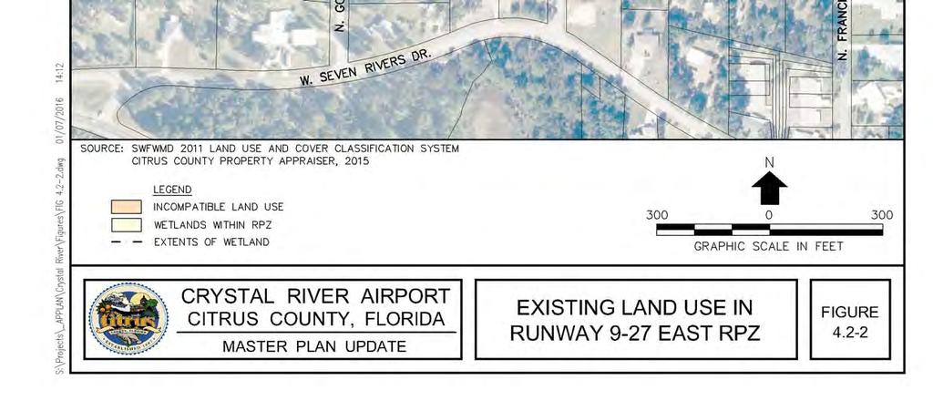


97
98 Section 4 RPZ Alternatives Approximately 12.8 acres (i.e., 92 percent) of the west RPZ is occupied with off-airport land uses. As the figure indicates, these land uses are located within the central portion of the RPZ, as well as the controlled activity area of the RPZ. Table quantifies on and off-airport land uses within the central portion of the RPZ and the controlled activity area of the west RPZ. Location Off-Airport Land Use Table Land Uses in Runway 9-27 West RPZ Central Portion of the RPZ Controlled Activity Area of the RPZ Total Shopping Center US Highway Other On-Airport Airfield TOTAL Source: URS, December Figure illustrates the land use inside the RPZ on the east end of Runway Unlike the RPZ on the west end of the runway, nearly the entire east RPZ is located on-airport property. Only 0.5 acres of the RPZ is located off-airport property and that portion of the RPZ is occupied by forested land owned by the Seven Rivers Golf and Country Club and vacant roadway rightof-way. The majority of on-airport the land use inside this RPZ is forested and a portion of the forested land is designated wetland according to Southwest Florida Water Management District (SWFWMD) data. The figure indicates that 9.3 acres of wetland are located inside the extents of the RPZ. Other land uses inside the east RPZ include airfield and North Golf Course Drive a two-lane roadway which provides access to West Seven Rivers Drive. Table quantifies on and offairport land uses within the central portion of the RPZ and the controlled activity area of the RPZ. Table Land Uses in Runway 9-27 East RPZ Location Land Use Central Portion of Controlled Activity the RPZ Area of the RPZ Total Off-Airport Forested Wetlands On-Airport N. Golf Course Drive Other On-Airport TOTAL Source: URS, December Crystal River Airport Master Plan Update
99 Section 4 RPZ Alternatives 4.3 PROPOSED LAND USE CHANGES IN THE RPZ The FDOT is planning to widen the portion of US Highway 19 located west of the Airport from two lanes in each direction to three lanes in each direction. The project is proposed to accommodate future traffic demand in a safe and efficient manner. The FDOT conducted a Project Development and Environmental (PD&E) Study for improvement alternatives along US 19 (SR 55) from south of US 98 to North Dunnellon Road (CR 488) in Citrus County, Florida. The purpose of the PD&E Study was to provide documented environmental and engineering analyses to assist the FDOT and the Federal Highway Administration (FHWA) in reaching a decision on the type, location and conceptual design of the necessary improvements, in order to qualify the project for federal-aid funding of future development phases of the project. The PD&E Study also satisfied the requirements of the National Environmental Policy Act of 1969 (NEPA) and other Federal requirements in order to qualify the project for federal-aid funding of future development phases of the project. The Study documented the need for the improvements, and presented procedures utilized to develop and evaluate various improvement alternatives. The design year for the analysis was The study determined that the recommended alternative for the portion of roadway immediately west of the Airport consists of a six-lane divided urban typical section with three 12-foot travel lanes and a 4-foot bike lane in each direction separated by a 30-ft raised median. Sidewalks, 5 feet in width, are provided along both sides of the roadway, separated from the curb by a grass buffer strip. The proposed design speed for this typical section is 50 mph. Figure provides an illustration of the proposed roadway section as presented in the PD&E study. A review of the FDOT s First Five Year Plan for Fiscal Years 2015/2016 through 2019/2020 indicates that the proposed roadway improvements are programmed for construction in Engineering design of the proposed roadway improvements has already been completed NEED FOR PROPOSED ROADWAY IMPROVEMENTS The PD&E study indicated that the need for the proposed widening of US Highway 19 was established based on the evaluation of the following: Current quality of traffic operations in the study area; The expected future quality of traffic operations along US 19 under the No-Build Alternative; Traffic safety statistics for the period between 1995 and 1999; Consistency with local government comprehensive plans; and The projected socioeconomic growth within the study corridor. 4-5 Crystal River Airport Master Plan Update

100 Source: PBS&J, May CRYSTAL RIVER AIRPORT Citrus County, Florida MASTER PLAN UPDATE PROPOSED US 19 ROADWAY SECTION FIGURE 4.3-1
101 Section 4 RPZ Alternatives The PD&E study determined that the proposed project meets these criteria. 4.4 SPONSOR CONTROL OF RPZ LAND The Airport sponsor (Citrus County) has ownership control over approximately 1 acre (8 percent) of the land in the RPZ on the west end of Runway The remaining 12.8 acres are located off airport property. Land use control in the 12.8 acres of RPZ located off-airport are controlled by zoning powers of the City of Crystal River. All of this land is currently zoned High Intensity Commercial (CH). Current land use is consistent with current zoning. In summary, the airport sponsor does not control land use in the portion of the west RPZ located off airport property. The airport sponsor has control over land use in the majority of the east RPZ except for approximately one-half acre located in property owned by the Seven River Golf and Country Club. The one-half acre is not currently developed and therefore is compatible with airport operations. 4.5 FEDERAL, STATE AND LOCAL TRANSPORTATION AGENCIES Agencies with involvement and/or an interest in the proposed land use change (i.e., the proposed widening of US Highway 19) in the west RPZ include the FAA, FDOT, Citrus County, and the City of Crystal River. 4.6 IDENTIFICATION OF RPZ ALTERNATIVES Several alternatives were identified to address the proposed land use change in the west RPZ. Some of these alternatives include changes to runway lengths which result in shifts of the runway s RPZs. Consequently the figures presenting the alternatives depict the resulting declared distances 3 for takeoff and landing lengths in both directions. The alternatives include the following: Alternative 1 Displace Runway 9 Landing Threshold and Remove Obstructions This alternative includes a 200-foot displacement of the Runway 9 landing threshold in order to attain the required vertical clearance between the expanded US Highway 19 and the runway s 20:1 approach surface. Figure depicts the proposed highway expansion and the runway s Obstacle Clearance Surface (OCS) in plan and profile views. Certain obstructions, such as poles, signs and trees located on the west side of US Highway 19, would need to be lowered, removed or lighted in accordance with FAA design standards. Figure provides an illustration of this alternative along with the resulting declared distances. The resulting landing distance on Runway 9 will decrease from 4,555 feet to 4,355 feet. All other operating lengths will remain at 4,555 feet. 3 Declared distances are the distances an airport owner declares available for a turbine powered aircraft s operation. These distances may be less than the physical dimension of the runway in order to meet FAA design standards for runway safety areas and/or other required geometric clearances. 4-7 Crystal River Airport Master Plan Update
102
103
104 This page intentionally left blank.
105 Section 4 RPZ Alternatives Alternative 1A Displace Runway 9 Landing Threshold and Replace 200 Feet This alternative includes displacing the Runway 9 landing threshold by 200-feet and replacing the 200 feet of runway lost for landing on the east end of the runway. The same obstruction removal proposed for Alternative 1 would also occur with this alternative. Additional obstruction removal would be required in the approach to Runway 27 to provide a clear approach. Figure provides an illustration of this alternative along with the resulting declared distances. The landing distance on Runway 9 will be maintained at 4,555 feet. All other operating lengths will increase to 4,755 feet. Alternative 2 Displace Runway 9 Landing Threshold and Extend Runway 490 Feet This alternative includes displacing the Runway 9 landing threshold by 490-feet and extending the runway by 490 feet on the east end to maintain the existing runway length of 4,555 feet. The proposed displacement of the Runway 9 landing threshold would achieve a clear 20:1 OCS (please see Figure 4.6-4), except for some on-airport trees that could be removed, and would shift the RPZ eastward thereby reducing the amount of off-airport land use inside the RPZ. The landing threshold on Runway 27 would also be displaced by 130 feet to keep the RPZ on the east end of airport property from extending beyond the airport s eastern boundary. The southern portion of this RPZ would extend beyond the airport southern boundary. Figure depicts this alternative. Alternative 3 Displace Runway 9 Landing Threshold and Extend Runway 925 Feet This alternative would displace the Runway 9 landing threshold by 925 feet and would extend the runway by an equal length on the east end of the runway to maintain the current length of 4,555 feet. In essence, the runway would be shifted 925 feet to the east. This alternative would bring the RPZ on the west end of the runway entirely on airport property thereby achieving full compliance with FAA land use guidance. This alternative also includes a 565 foot displacement of the Runway 27 landing threshold in order to maintain the RPZ on the east end of the runway from extending beyond the airport s eastern boundary. Figure depicts this alternative. Alternative 4 - Tunnel US Highway 19 This alternative would consist of constructing a tunnel for the portion of US Highway 19 that passes through the RPZ on the west end of Runway Runway 9-27 would remain in its present location and maintain its current operating lengths. Alternative 4 is depicted in Figure COST ESTIMATES Cost estimates were prepared for the aforementioned alternatives and were based upon current market knowledge of bid prices for similar airport projects in Florida. The cost estimates include construction costs and program costs. Construction costs include all material and labor. A construction contingency of 25 percent is provided in the estimate for unknown items at this conceptual level of planning. Program costs include engineering design fees, construction management services, topographic survey, geotechnical investigations, utility location services and quality assurance and materials testing Crystal River Airport Master Plan Update
106


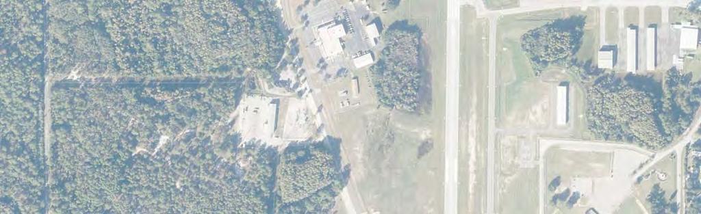


107
108 This page intentionally left blank.

109
110
111
112 This page intentionally left blank.


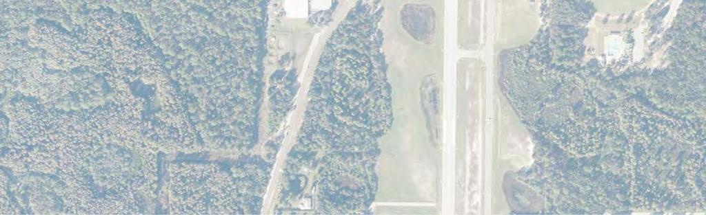


113
114 This page intentionally left blank.


115
116 Section 4 RPZ Alternatives Cost estimates are presented in 4 th Quarter, 2015 dollars. Escalation needs to be applied to carry these costs into future periods. Details of the cost estimates are provided in Appendix B. A detailed unit cost estimate was not prepared for Alternative 4. Instead major elements were identified and summarized to arrive at an estimated order-of-magnitude range. Table presents a summary of the cost estimates. Table Alternative Cost Estimates Alternative Description Estimated Cost 1 Displace Runway 9 and Remove Obstructions $780,000 1A Displace Runway 9, Remove Obstructions and Extend $4,420,000 Runway 200 Feet 2 Displace Runway 9 and Extend Runway 490 Feet $4,490,000 3 Displace Runway 9 and Extend Runway 925 Feet $5,550,000 4 Tunnel US 19 $25 to $30 million Source: AID, July Note: The estimated cost for Alternative 4 includes the cost of tunnel construction. It does not include roadway construction which would be incurred regardless of whether this alternative is implemented. Alternative 1 is the least costly, because it does not include runway construction. Alternative 4 is the most expensive due to the complexity of tunnel construction. Alternatives 1A, 2 and 3, though similar, vary due to the difference in runway length. Although Alternative 1A includes a shorter runway extension than Alternatives 2 and 3, it still requires the same obstruction removal required on the west end with Alternative 1. Consequently, its cost is nearly as high as Alternative PRACTICABILITY ASSESSMENT AND IDENTIFICATION OF PREFERRED ALTERNATIVE The FAA s memorandum entitled Interim Guidance on Land Use within Runway Protection Zones requires a practicability assessment based on cost, constructability and other factors. For the purpose on this assessment the following factors were considered: Operational Impacts Compliance with FAA Land Use Guidance Cost Constructability Other Factors 4-22 Crystal River Airport Master Plan Update
117 Section 4 RPZ Alternatives OPERATIONAL IMPACTS One of the most important items when evaluating the practicability of RPZ alternatives is the impact that they would have on existing and proposed aircraft operations. Section 3 indicated that the Airport presently serves a range of business jets raging from very light jets such as the Cessna Mustang and Embraer Phenom 100 to midsize business jets such as the Bombardier Challenger 600 and the Dassault Falcon 900. These aircraft conduct hundreds of operations at the Airport each year and are their numbers are projected to grow in future years. Many of these aircraft require the entire length of Runway 9-27 under demanding conditions (i.e., high temperatures, high density altitude and or wet pavement conditions). A Phenom 100 is currently based at the Airport. Review of the runway length requirements of this aircraft indicated that a runway length of approximately 4,600 feet (dry runway) to 5,600 feet (wet runway) is required during hot day conditions. Consequently the existing runway length of 4,555 feet is needed to support current operations by this aircraft. Alternatives that decrease available runway length will adversely impact existing and potential future aircraft operations. As noted in Section 3, a runway length of up to 5,400 feet would be justified at the Airport whenever annual business jet operations reach 500. Alternative 1 has the potential to adversely impact existing aircraft operations because it reduces the landing length on Runway 9 to 4,355 feet from 4,555 feet, a reduction of 200 feet. This will reduce available landing weights for certain aircraft operators and may result in certain operators choosing not to operate at Crystal River Airport. Alternative 1A maintains a minimum operating length of 4,555 feet in both directions and therefore would not have an adverse operational impact to any operators. Declared distances for takeoff in both directions would increase to 5,755. Declared distances is a process whereby an airport owner declares a certain portion of a runway as being available for takeoff or landing in order to meet runway safety area, runway object free area or RPZ requirements in a constrained environment. Consequently, this usually results in a portion of the runway not being used for takeoff or landing calculations. Declared distances were applied to Alternative 1A to show resulting operational lengths and to Alternatives 2 and to improve compliance with FAA guidance for land use compatibility in RPZs. The application of declared distances can result in a longer distance being available for takeoff than landing or vice versa. Alternative 2 maintains a minimum operating distance of 4,555 feet in both directions. While certain declared distances would increase, for example the distance available for takeoff on Runway 9 would increase to 4,915 feet, the shortest declared distance in both directions would remain 4,555 feet Crystal River Airport Master Plan Update
118 Section 4 RPZ Alternatives In terms of operational impacts, Alternative 2 would not increase operational capability above what presently exists at the Airport, because the takeoff distance available and takeoff run available on Runway 27 would not increase beyond the current runway length of 4,555 feet. Alternative 3 also maintains a minimum operating distance of 4,555 feet in both directions. Only the accelerate-stop distance would increase with Alternative 3 (to a length of 5,480 feet). The takeoff distance available and the takeoff run available would both remain at 4,555 feet. Consequently, Alternative 3 would also not provide an increase in operational capability compared to the existing runway length. Alternative 4 would avoid the use of declared distances. The existing runway length of 4,555 feet would be maintained and no change to operating conditions would occur with this alternative. Table summarizes the declared distances for the five alternatives. The shortest of the ASDA, TORA or TODA is the controlling factor for takeoff and the LDA is the controlling factor for landings. Furthermore, the shortest of these distances in either direction will be the controlling factor for flight planning purposes. Table Comparison of Alternatives Declared Distances Declared Distances Alternative TORA TODA ASDA LDA 1 / Runway 9 4,555 4,555 4,555 4,355 1 / Runway 27 4,555 4,555 4,555 4,555 1A / Runway 9 4,755 4,755 4,755 4,555 1A / Runway 27 4,755 4,755 4,755 4,755 2 / Runway 9 4,915 4,915 5,045 4,555 2 / Runway 27 4,555 4,555 5,045 4,915 3 / Runway 9 4,915 4,915 5,480 4,555 3 / Runway 27 4,555 4,555 5,480 4,915 4 No Declared Distances Source: URS, July, COMPLIANCE WITH FAA LAND USE GUIDANCE Alternatives 1 and 1A would not improve the west RPZ s compatibility with FAA guidance because the proposed relocation of the Runway 9 landing threshold would result in the establishment of separate approach and departure RPZs on the west end of the runway. Although the approach RPZ would shift 200 feet to the east, the departure RPZ would remain in its present location. Consequently, the amount and types of off-airport land uses inside the RPZ would remain the same as with existing conditions Crystal River Airport Master Plan Update
119 Section 4 RPZ Alternatives Alternative 2 would improve compliance with FAA land use guidance by shifting the RPZ on the west end of the runway 490 feet to the east. This shift would remove the existing strip shopping center located on the west side of US 19 from the RPZ. However, the shopping center parking lot and one retail establishment fronting US Highway 19 would still be within the RPZ. This alternative would reduce the amount of incompatible land use inside the west RPZ from approximately 11.6 acres to 5 acres; a reduction of 56 percent. Alternative 3 would provide full compliance with FAA land use guidance for RPZs by bringing the west RPZ entirely on airport property. Alternative 4 would prevent the introduction of additional incompatible land uses into the west RPZ, but would not address existing incompatible land uses. In summary, Alternative 3 is the only alternative that would achieve full compliance with FAA land use guidance in the west RPZ. Alternative 2 is the second most effective alternative at improving land use compatibility in the west RPZ. The amount of off-airport land that would be located inside the east RPZ would not change with Alternatives 1 and 4, but would increase with Alternatives 2 and 3 (from approximately 0.5 acres to 2 acres) because these alternatives shift the RPZ approximately 360 feet to the east. However, the land use in this area consists of forested land. Therefore, if property acquisition and/or avigation easements were acquired in conjunction with these alternatives, then the amount of incompatible land inside the east RPZ would not change. Table provides a summary of the land use compatibility in both RPZs with the alternatives. Table Comparison of Alternatives RPZ Land Use Compatibility Change in Compatible Land Use Alternative West RPZ East RPZ No change (11.6 acres of 1 No Change incompatible land use) 1A Source: URS, July COST IMPLICATIONS No change (11.6 acres of incompatible land use) Reduces incompatible land use from 11.6 acres to 5 acres. Reduces incompatible land use from 11.6 acres to 0 acres. Reduces incompatible land use from 11.6 acres to 10.5 acres. No Change No change with acquisition of property or avigation easement. No change with acquisition of property or avigation easement. No Change As noted in the preceding section, Alternative 1 is the least costly alternative at $780,000 due to the minimal amount of runway construction required. Alternatives 1A, 2 and 3 are more costly due to their runway extensions of 200-feet, 490-feet and 925-feet, respectively. Alternative 4 is the most expensive alternative at an estimated cost of $25 to $30 million Crystal River Airport Master Plan Update
120 Section 4 RPZ Alternatives CONSTRUCTABILITY Factors affecting constructability include the following: Complexity Environmental Factors Property or Easement Acquisition The following paragraphs address each of the items Complexity Alternatives 1 through 3 are straightforward in terms of construction issues. Only Alternative 4 presents more complex and high risk construction issues. Very few roadway tunnels exist in the State of Florida due to a combination of factors, including high construction cost, high water tables and high intensity rainfalls which present drainage challenges. For these reasons Alternative 4 presents an order-of-magnitude higher complexity and risk than the other three alternatives Environmental Factors Alternative 1 would not result in construction within environmentally sensitive resource areas and would not require the preparation of environmental documentation beyond a categorical exclusion. Alternatives 1A, 2 and 3 require either earthwork for the extended runway safety area or runway and taxiway construction in wetlands. The amount of wetlands with these alternatives could be up to 14 acres depending on the amount ground disturbance and tree clearing implemented. Filling these wetlands would also require appropriate permitting and mitigation measures. An Environmental Assessment (EA) would be required for construction of these alternatives to address wetland and other potential environmental impacts. Costs for environmental mitigation are included in the cost estimate for each alternative. Alternatives 1A, 2 and 3 would result in the runway being shifted 200, 490 feet and 925 feet eastward respectively. Any noise impacts associated with these shifts would need to be examined as part of an environmental assessment. An EA would also be required for the construction of Alternative 4. However, the project sponsor for that environmental documentation would be FDOT rather than Citrus County. In summary, Alternatives 1A, 2 and 3 present larger challenges in terms of environmental constraints than Alternatives 1 and Property or Easement Acquisition Alternatives 1 and 4 would not require any property or easement acquisition. Alternatives 1A, 2 and 3 would require either property or easement acquisition for land that would fall within the limits of the east RPZ. The amount of property acquisition required ranges from approximately 1 acre with Alternative 1A to approximately 2 acres with Alternative 2 and Crystal River Airport Master Plan Update
121 Section 4 RPZ Alternatives OTHER FACTORS Alternative 3 would result in long displaced thresholds on both ends of the runway and greater taxiway distances compared to other alternatives. Implementation of Alternative 4 would require the construction of temporary roadways while the tunnel for US Highway 19 is constructed. Given the large number of businesses located on the west side of the highway, it is possible that the temporary roadways would need to be constructed on the east side of the current highway and could adversely impact the existing approach to Runway 9 and could also potentially adversely impact aircraft operations on Runway 18/36. Alternative 4 presents several challenges that are not applicable to Alternatives 1 through 3. First, the project would require the approval and participation of FDOT. There is no assurance that FDOT would support this alternative or would participate in its funding. Table provides a summary of the practicability assessment. On the basis of the practicability assessment, Alternative 1A was recommended by the study consultant as the preferred alternative. This alternative avoids the adverse operational impacts that would result from implementation of Alternative 1 and has the second lowest cost of all the alternatives. Although it does not reduce incompatible land uses in the west RPZ, it would eliminate obstructions to the Runway 9 approach surface. Alternative 1A will have less land disturbance on the east end of the runway and therefore, will have less wetland impacts than Alternatives 2 and 3. It also has a lower potential for noise impacts compared to Alternatives 2 and 3. Alternative 1 is not recommended due to the fact that it does not improve land use compatibility in the runway s west RPZ, as well as its reduction of runway length available for landings and subsequent adverse impacts to aircraft operations. Alternatives 2 and 3 are not recommended due to their higher costs and displaced thresholds. Alternative 4 is not recommended due to its high cost and construction complexity, as well as the fact that multiple agencies would need to agree to its implementation. This alternative has significantly higher risk in terms of obtaining approval and therefore is less likely to be successfully implemented in comparison to the other alternatives Crystal River Airport Master Plan Update
122 Section 4 RPZ Alternatives Table Summary of Practicability Assessment Item Alternative 1 Alternative 1A Alternative 2 Alternative 3 Alternative 4 Operational Impacts Compliance with FAA s RPZ Land Use Guidance Shortens landing distance on Runway 9 to 4,355 feet. Would adversely impact certain aircraft operations by reducing available landing weights. Maintains a minimum runway length of 4,555 feet in both directions. No adverse impacts to aircraft operations. Maintains a minimum runway length of 4,555 feet in both directions. No adverse impacts to aircraft operations. Maintains a minimum runway length of 4,555 feet in both directions. No adverse impacts to aircraft operations. Maintains existing runway length. No adverse impacts to aircraft operations. Decreases Decreases Decreases incompatible land No improvement in No improvement in incompatible land incompatible land use in the east land use land use use in the east use in the east RPZ from 11.6 compatibility. compatibility. RPZ from 11.6 RPZ from 11.6 acres to 10.5 acres to 5 acres. acres to 0 acres. acres. Cost $780,000 $4,420,000 $4,490,000 $5,550,000 Est. $30,000,000 Construction Complexity Environmental Factors Property/Easement Acquisition Other Factors Source: URS, July Low Medium Medium Medium High Minimal no impacts to wetlands. None Also requires obstruction removal, marking or lighting. Would fill approximately 0.8 acres of wetlands. 0.8 acres for southern portion of east RPZ Requires a displaced threshold on Runway 9. Would fill approximately 2.5 acres of wetlands. 2 acres for southern portion of east RPZ Requires displaced thresholds on both ends of the runway. Would fill approximately 4.4 acres of wetlands. 2 acres for southern portion of east RPZ Requires long displaced thresholds and greater taxiway distances. Minimal no impacts to wetlands. None Potential impacts to airfield operations during construction Crystal River Airport Master Plan Update
123 Section 5 Alternatives SECTION 5 ALTERNATIVES 5.1 INTRODUCTION This section identifies and analyzes alternatives for providing the facility requirements identified in Section 3. Alternatives are presented on the following pages using a combination of text and figures. Advantages and disadvantages associated with each alternative are identified as necessary to assess the relative merits of each option. 5.2 AIRFIELD ALTERNATIVES RUNWAYS Runway 9-27 The facility requirements section determined that a runway length of up to 5,400 feet should be considered when 500 or more annual operations can be documented for the family of design aircraft (i.e., B-II turbojets). Several runway alternatives were developed and presented in the preceding section in conjunction with an assessment of options for addressing Runway Protection Zone (RPZ) compliance. These alternatives were presented to and coordinated with the Citrus County Airport Advisory Board (AAB), as well as the Federal Aviation Administration (FAA) and the Florida Department of Transportation (FDOT). The Citrus County AAB voted in favor of a modified version of Alternative 1 (designated Alternative 1B) that includes an extension of 645 feet on the east end of the runway to compensate for a 200-foot displacement of the Runway 9 landing threshold due to the widening of US Highway 19 and to attain a desired future runway length of 5,000 feet. After reviewing this proposed action, both the FAA and FDOT declined to participate in funding Alternative 1B. Correspondence received from the FAA regarding this issue is contained in Appendix C. Consequently, the only viable alternative for Runway 9-27 in the short-term is to displace the landing threshold for Runway 9 by 200 feet in order to keep the runway s approach surface clear of vehicles on the widened US Highway 19. Once 500 or more annual operations can be documented for the family of design aircraft, the proposed action for Runway 9-27 should be to implement Alternative 1B. Figure illustrates Alternative 1B Runway The facility requirements section indicates that a length of up to 3,080 feet is justified for Runway on the basis of the existing critical aircraft (i.e., a Cessna 182RG). The existing length of the runway is 2,666 feet. Furthermore, large displacements currently exist on both landing thresholds due to obstructions in the approach surfaces. These obstructions consist of buildings and vegetation located beneath the approach to Runway 18 as well as trees and West Venable Street located beneath the approach to Runway 36. The runway s landing thresholds are displaced 192 feet on Runway 18 and 819 feet on Runway 36. This results in a landing length of 2,474 feet on Runway 18 and 1,847 feet on Runway Crystal River Airport Master Plan Update
124 Section 5 Alternatives The displacement to the Runway 18 landing threshold can be eliminated through the acquisition and removal of buildings, structures and vegetation that penetrates the approach surface in the RPZ. The displaced threshold on the south end of the runway can be reduced to approximately 410 feet by clearing the tall trees on land south of West Venable Street. An easement for access to this property to clear these trees was obtained by Citrus County from the property owner in Once this tree clearing is completed, the future controlling obstacle at the south end of the runway will be proposed traffic light poles on the northeast and southeast corners of the widened US Highway 19 and West Venable Street intersection. Extending Runway 18/36 on the south end of the runway is not feasible due to the presence of West Venable Street. Relocation of the street would require property acquisition and would be an expensive undertaking. Likewise, extending the runway on the north end may require the acquisition of additional off-airport properties located north of Godfrey Lane in order to comply with FAA land use guidance for the RPZ. Consequently, the recommended course of action is to focus on the reduction and/or elimination of the existing displaced thresholds on each end of the runway. This can be accomplished through compliance with FAA design standards for geometric clearances and the clearance of existing obstructions to the approach surfaces. The elimination of the displaced landing threshold on the north end of the runway could be accomplished through the acquisition of the two buildings fronting US Highway 19, as well as one residence along North Lindbergh Drive. Acquisition of these properties and removal of the existing structures would eliminate obstructions to the Runway 18 approach surface and would also improve land use compatibility within the existing RPZ. Figure illustrates the potential length of Runway with implementation of these actions RUNWAY SAFETY AREAS AND OBJECT FREE AREAS Besides the issue of runway length, the Facility Requirements section noted conditions associated with Runway 9-27 that do not meet current airfield design standards. These issues include a lack of blast pads at each end of the runway, a fence located inside the east end of the Runway Safety Area (RSA) and Runway Object Free Area (ROFA), and the presence of the segmented circle and wind cone inside the ROFA of both runways. These conditions can be addressed through specific capital improvements. A blast pad that meets design standards should be constructed at the east end of Runway 9-27 in conjunction with the proposed runway extension. A blast pad is not recommended for the west end of the runway due to the fact that it would impinge on the turf runway. The fence located inside the east end of the RSA and ROFA for Runway 9-27 should be moved outside of both areas to meet design standards. Resolution of these deficiencies could be achieved most cost effectively in conjunction with the proposed extension of Runway Crystal River Airport Master Plan Update


125 FIGURE DISPLACE RUNWAY 9 LANDING THRESHOLD 200' AND EXTEND RUNWAY ' ALTERNATIVE 1B MASTER PLAN UPDATE CITRUS COUNTY, FLORIDA CRYSTAL RIVER AIRPORT
126 This page intentionally left blank.
127 BRL BRL BRL FIGURE RUNWAY WITH IMPROVEMENTS CRYSTAL RIVER AIRPORT CITRUS COUNTY, FLORIDA MASTER PLAN UPDATE
128 This page intentionally left blank.
129 Section 5 Alternatives Figure depicts options for relocating the segmented circle and wind cone. Site 1 is located where a water detention pond is currently located at the south end of the aircraft parking apron, west of Taxiway B. Relocation of the pond would be required in order for this site to be a viable location. However, a portion of this pond may also need to be relocated to accommodate other airfield improvements and therefore, may be a viable course of action if undertaken in conjunction with those projects. Site 1 is highly visible to aircraft taxiing to and from the terminal area. However, it is located closer to a forested area east of Taxiway B which may adversely impact the ability of the wind cone to accurately indicate prevailing wind conditions when prevailing winds are from the northeast. Site 2 is located south of Runway 9-27, east of the FNG facilities and north of West Venable Street. This site is highly visible to aircraft in flight, but would not be visible to aircraft taxing from the terminal area to Runway 9-27 or Runway Furthermore, a forested area west of this site would need to be cleared of trees that could adversely impact the wind cone from indicating prevailing wind conditions. This area of trees was previously cleared and should be cleared again to eliminate obstructions inside the ROFA and Part 77 airspace surfaces. Site 3 is located on the south end of the existing aircraft parking apron. This site would eliminate 2 to 3 aircraft tie-down positions. However, field visits indicate that these tie-down positions are rarely used at current levels of demand. This area is highly visible from the air and to aircraft taxiing from the terminal area to Runway However, this site is also located close to the forested area east of Taxiway B which may impact the ability of the wind cone to accurately indicate prevailing wind conditions when winds are from the northeast. Review of these sites with county staff indicated that Site 2 is the preferred future location for the relocation of the segmented circle and wind cone. A supplemental wind cone is recommended for Runway due to the fact that the relocated wind cone would not be visible to aircraft taxiing to the west end of Runway 9-27 or either end of Runway The supplemental wind cone could be located approximately 90 feet northwest of the current wind cone. A supplemental wind cone in that location would meet FAA design standards TAXIWAYS The Facility Requirements section noted that the portion of Taxiway A located at the approach end of Runway 9 does not meet FAA design standards due to its lack of a standard 90 degree connection to Runway 9. This deviation from design standards could be remedied by reconfiguring the west end of the taxiway to provide a standard 90 degree entrance as shown in Figure This action requires constructing new pavement, the removal of existing pavement and the modification or relocation of a portion of the existing water retention pond located west of Taxiway A. 5-7 Crystal River Airport Master Plan Update
130 CRYSTAL RIVER AIRPORT CITRUS COUNTY, FLORIDA MASTER PLAN UPDATE RELOCATION OF WIND CONE WITH SEGMENTED CIRCLE FIGURE 5.2-3
131 CRYSTAL RIVER AIRPORT CITRUS COUNTY, FLORIDA MASTER PLAN UPDATE FUTURE TAXIWAY A GEOMETRY FIGURE 5.2-4
132 Section 5 Alternatives Figure also depicts the limits of the Taxiway Safety Area (TSA) from the reconfigured taxiway. The area inside the TSA, plus the required embankment outside the TSA, would require filling a portion of the adjacent water retention pond. Final engineering design would determine how to best replace the water retention capability lost in this pond HOLDING BAYS Consultation with Fixed-Base Operator (FBO) management noted that operational delays occur at the Airport due to the inability for aircraft to by-pass other aircraft at either end of Runway This need is compounded by flight training that occurs at the Airport and the limited number of taxiways. The need is especially critical at the approach end of Runway 9 where Taxiways B and A converge close to where aircraft hold before departing on Runway 9. The latest FAA design standards discourage the construction of holding bays that consist of an area of contiguous pavement adjacent to the taxiway. Instead the design standards call for independent holding areas with the ability for taxiing aircraft to bypass each aircraft holding area. This design requires greater depth to enable the bypassing aircraft to pass behind the holding aircraft while also meeting wingtip separation requirements. This design is difficult to provide at Crystal River Airport due to the lack of available property. Figure illustrates potential locations and configurations for holding bays along Taxiway B. These holding bays would essentially be bypass taxiways rather than a typical holding bay configuration that accommodate multiple aircraft holding positions due to property constraints that negate the ability to provide the recommended configuration. The first location is at the approach end of Runway 9 and would be located north of the reconfigured Taxiway A. It would provide the ability for two aircraft to hold in this location while keeping the intersection of Taxiway A and B clear for other taxiing movements. This location would require a portion of the water retention pond located at the south end of the aircraft parking ramp to be relocated. A review of the Airport s stormwater master plan indicates that the water retention capacity currently provided in the shallow portion of this pond could be replaced by expanding a pond on the east side of Taxiway B. This location also requires the elimination of the southernmost tie-down parking position on the aircraft parking apron due to the need to provide the required amount of wingtip clearance for aircraft using the holding bay (see Figure 5.2-5). The second holding bay location is at the approach end of Runway 27. This location suffers from several constraints including the proximity of North Golf Course Drive, adjoining wetlands, the Airport s property boundary and a water retention pond. Construction of a holding bay/bypass taxiway in this location would require the relocation of a portion of North Golf Course Drive which, in turn, would impact adjoining wetlands. Consequently the cost of a holding bay in this location would be higher due to these impacts Crystal River Airport Master Plan Update
133 FIGURE TAXIWAY BY-PASS / HOLDING BAY OPTIONS CRYSTAL RIVER AIRPORT CITRUS COUNTY, FLORIDA MASTER PLAN UPDATE
134 This page intentionally left blank.
135 Section 5 Alternatives Another consideration with this location is that the holding bay would no longer be located at the approach end of Runway 27 after the runway is extended to the east. Therefore, a better approach may be to incorporate a holding bay into the design for the future runway extension because North Golf Course Drive would be closed as part of that project thereby eliminating the need to relocate a portion of the roadway. The third holding bay location is not at a runway end. It is located approximately 1,000 feet west of the approach end of Runway 27. This location is proposed because it is free of the physical and environmental constraints that would impact construction of a holding bay at the approach end of Runway 27. This location would not encroach on wetlands or water retention ponds and therefore could be constructed at lower cost. This location would still provide the ability for aircraft to bypass, but would require the use of a holding bay that is not in a traditional or intuitive location. Therefore, a holding bay in this location may not receive the same level of use as one located at the approach end of the runway. None of the three holding bay locations are recommended for the following reasons: None of the locations can accommodate a standard holding bay configuration. Location 1 is constrained by both the proposed reconfiguration of the entrance of Taxiway A to the approach end of Runway 9 and the aircraft parking apron to the north. Location 2 and 3 would not be at the approach end of Runway 27 once the runway is extended and therefore would be at sites that are not intuitive to pilots. The recommended alternative for providing a holding by-pass capability at the approach end of Runway 27 is for a holding bay to be incorporated in the design of the future runway extension NAVIGATIONAL AIDS Airport Beacon As noted in the Inventory and Facility Requirements sections, the Airport s existing rotating beacon is difficult to see from points northwest of the Airport according to pilot reports. Visual observations from the ground indicate that this problem is due to tall trees in the vicinity of the beacon, especially northwest of the terminal building. Options for resolving this problem include trimming trees, replacing the existing beacon tower with a taller tower or relocating the beacon to another site. Visual observations indicate that the existing beacon is mounted on a standard tubular steel tower. These towers typically place the beacon at an elevation of approximately 55 to 60 feet above ground level (AGL). A review of existing survey data indicates that the tallest trees in the vicinity of the tower have elevations that exceed 70 feet. Therefore, it is very likely that surrounding trees obscure the beacon s light beam and are the cause of the visibility problems reported by pilots Crystal River Airport Master Plan Update
136 Section 5 Alternatives Potential sites for relocating the rotating beacon are shown in Figure Site 1 is essentially the same location as the existing beacon, but slightly farther south to avoid conflicts with other recommended terminal area development. A tower taller than the existing tower could be installed in this location. Site 2 is located north of the county owned T-Hangars. This site is also located next to existing power lines that serve the T-hangars and immediately west of Bicentennial Park. It is also closer to Runway 9/27, which is the only runway available for nighttime use and is farther away from residential areas north of the Airport. According to Advisory Circular (AC) 150/ H, Design and Installation Details for Airport Visual Aids, the standard heights for structural steel towers that support airport beacons include 51, 62, 75, 91, 108, 129, and 152-feet. A tower height of 75 feet along with a high intensity beam aimed 5 degrees above horizontal would ensure that the light beam clears the tallest trees in the vicinity. It is recommended that a new rotating beacon be constructed at Site 1 immediately south of the existing tower. Electrical service already exists to support a beacon in this location and the beacon will be readily visible to employees located at the FBO TERMINAL AREA ALTERNATIVES The Facility Requirement section noted that additional terminal space is needed for flight training purposes with a demand for up to 7,500 square feet of space. Figure presents four potential sites for a facility. Site 1 is located directly east of the existing FBO facility in a cleared grass area. Site 2 is located directly south of Site 1 and east of the existing apron and fuel farm. This site extends into forested areas that may contain wetlands. Site 3 is located north of North Lindbergh Drive in a partially cleared area. Site 4 is located at the far north end of the existing aircraft parking apron. Review of these sites revealed that Site 2 would most likely require filling of wetlands and therefore, permits and mitigation that would increase development costs. Site 3 is located farther from the FBO that the other sites and is on the opposite side of North Lindbergh Drive. Consequently, users would have farther walking distances and would have to cross a roadway to reach each facility. Site 4 cannot meet height clearance requirements from Runway and therefore was discarded from further consideration. Given the shortcomings of sites 2 through 4, Site 1 is the preferred location for a future flight training facility. Review of these sites with the Citrus County AAB indicated that Site 1 is favored, but a change in orientation (to provide the longer dimension in the north-south direction) is desired to maximize the potential for automobile parking in front of the facility Crystal River Airport Master Plan Update
137 CRYSTAL RIVER AIRPORT CITRUS COUNTY, FLORIDA MASTER PLAN UPDATE POTENTIAL ROTATING BEACON SITES FIGURE 5.2-6
138 CRYSTAL RIVER AIRPORT CITRUS COUNTY, FLORIDA MASTER PLAN UPDATE FUTURE BUILDING OPTIONS FIGURE 5.2-7
139 Section 5 Alternatives Figure depicts a potential layout of a flight training facility at this site with a total footprint of 5,000 square feet rather than 7,500 square feet. Further review of conceptual space allocation for a dedicated flight training building with FBO personnel revealed that a single level stand-alone building of up to 5,000 square feet would provide sufficient space for a flight training facility. The site plan shown in Figure should be used as the basis for more detailed facility design when this project is initiated Hangars and Aprons Alternatives are not proposed for other recommended terminal facilities such as hangars and aprons. It is recommended that future development of these facilities occur in a manner consistent with previous site development and as recommended by the previous master plan with most development occurring north of Runway 9-27 and west and south of Bicentennial Park. Sections 6 and 7 describe the proposed hangar and apron development FUELING The Facility Requirements section noted that a self-serve fueling facility is desired. Consultation with FBO management indicated that the desired location for the facility is next to the existing fuel farm as depicted in Figure This location currently provides sufficient apron for aircraft that would require access to the facility, and would enable the self-serve facility to use the existing fuel farm storage tanks, thereby lowering the facility s construction cost. It is recommended that the self-serve facility provide capability for AVGAS and tie into the existing AVGAS storage tanks. 5.3 ENVIRONMENTAL CONSIDERATIONS Figure presents an environmental resource map of airport property and surrounding areas. Based on this map, review of potential environmental considerations are focused on biological resources, FDOT Section 4(f) resources, floodplains, historic resources, noise and noise-compatible land use, and wetlands. The following sections identify and discuss environmental considerations for planned improvements at Crystal River Airport (CGC) based on Figure and the alternatives presented in Section BIOLOGICAL RESOURCES The Endangered Species Act of 1973 (ESA), as amended (87 Stat. 884; 16 United States Code USC) 1531 et seq.), requires that all federal agencies undertake programs for the conservation of endangered and threatened species and prohibits federal agencies from authorizing, funding, or carrying out any action that would jeopardize a listed species or destroy or modify its critical habitat as designated in 50 Code of Federal Regulations (CFR) parts 17 and 226. Projects that would otherwise jeopardize a federally listed species or impact its critical habitat must contain conservation measures or habitat mitigation that removes the jeopardy. State listed species are those animal and plant species protected by the State of Florida pursuant to Chapter 68A-27 Florida Administrative Code (F.A.C.) and Chapter 5B-40, F.A.C., respectively Crystal River Airport Master Plan Update
140 CRYSTAL RIVER AIRPORT CITRUS COUNTY, FLORIDA MASTER PLAN UPDATE FLIGHT TRAINING BUILDING SITE PLAN FIGURE 5.2-8
141 CRYSTAL RIVER AIRPORT CITRUS COUNTY, FLORIDA MASTER PLAN UPDATE SELF-SERVE FUELING LOCATION FIGURE 5.2-9
142 LEGEND Cemeteries [k [e Parks and Recreational Areas Potential Historic Structures Wetlands Floodplains Zone A [e º Zone AE Feet 0 1,300 Path: S:\Projects\_APPLAN\Crystal River\Environmental Considerations\mxd\170504_Figure CGC Environmental Resource Map_rev0.mxd, Date Saved: 5/8/2017 9:36:38 AM [e [e [e [e [e[e[e [e MASTER PLAN UPDATE [k CRYSTAL RIVER AIRPORT Sources: AECOM, 2017; FDEP, 2015; FDOT APLUS, 2014; FEMA, 2014; SWFWMD, 2011; UFL, [k ENVIRONMENTAL RESOURCE MAP FIGURE 5.3-1
143 Section 5 Alternatives An official species list obtained from the U.S. Fish and Wildlife Service (FWS) identifies the following threatened, endangered, proposed and candidate terrestrial species protected under the ESA that may occur within the boundaries of proposed improvements at CGC; Florida Scrub-jay (threatened); Red Knot (threatened); Red-cockaded Woodpecker (endangered); Wood Stork (threatened); Eastern Indigo Snake (threatened). No critical habitat areas were identified by the FWS in the area of CGC. During environmental review and permitting of any proposed developments, field reviews of the project areas should be conducted to ascertain habitat boundaries and presence/absence of the above-referenced ESA species and any other state-listed species. Findings and a statement of potential impact would be documented in a Biological Assessment (BA), which would be submitted to FWS for review and concurrence pursuant to Section 7 of the ESA. To the extent these species are present in the project areas, relocation, disturbance or taking permits may need to be secured from the Florida Fish and Wildlife Conservation Commission (FWC) and/or FWS prior to project construction. Implementation of agency-approved Standard Protection Measures for the Eastern Indigo Snake (revised August 12, 2013) would be implemented during construction if suitable habitat for the species occurs within project areas DEPARTMENT OF TRANSPORTATION SECTION 4(f) RESOURCES Section 4(f) of the FDOT Act of 1966 (re-codified and renumbered as Section 303(c) of 49 USC) provides protection for publicly-owned parks, recreational areas, wildlife, and waterfowl refuges; and significant historic sites (properties listed on or eligible for listing on the National Register of Historic Places (NRHP). The term Section 4(f) resource refers to any specific site or property meeting DOT Act criteria. Primarily, Section 4(f) protections prevent more than a minimum physical use (i.e., land taking or development) of the resource without mitigation. Further, Section 4(f) prevents against constructive use of the resource. Constructive uses represent impacts to the recreational use and character of an eligible resource that is unrelated to physical taking (e.g., increased noise, decreased air quality, deterioration of the view-shed), Nearby Section 4(f) eligible resources to CGC include Bicentennial Park adjoining airport property, as well as the Seven Rivers Golf Course and Country Club to the northeast of CGC (Figure 5.3-1). Historic structures to the west of the airport are also eligible for Section 4(f) protections and are further discussed in Section Proposed developments at CGC would not cause any physical use of these properties such that Section 4(f) requirements would be triggered. However, due to the proximity of these properties to airport operations, constructive use would need to be evaluated during the environmental review and permitting process in terms of changes in noise exposure and aesthetic character of the Section 4(f) resources. If constructive use impacts could not be reasonably avoided, compensatory mitigation of the impacts would be required prior to FAA issuing environmental approval Crystal River Airport Master Plan Update
144 Section 5 Alternatives FLOODPLAINS Executive Order (EO) 11988, Floodplain Management, defines floodplains as the lowland and relatively flat areas adjoining inland and coastal waters including flood prone areas of offshore islands. Floodplain areas are differentiated primarily based on flood frequency and intensity. Specifically, areas subject to a one (1) percent or greater chance of flooding in a given year are commonly referred to as the 100-year floodplain. Further, areas subject to a 0.2 percent chance of flooding in a given year are referred to as the 500-year floodplain. The entire CGC property is located within the 100-year floodplain established by the Federal Emergency Management Agency (FEMA) as per Flood Insurance Rate Map (FIRM) 12017C0302D, effective September 26, Environmental review and permitting of any proposed developments at CGC would need to demonstrate compliance with DOT Order , Floodplain Management and Protection, as well as EO 11988, which each compel Federal agencies to avoid significant floodplain encroachments associated wherever practicable, minimize the effects of federal actions on floodplains, and preserve natural and beneficial floodplain values that are adversely affected. Significant floodplain encroachments involve actions that result in: 1) considerable probability of loss of human life; 2) likely future damage that could be substantially costly or widespread, including loss of a vital transportation facility; and/or 3) notable adverse impact on natural and beneficial floodplain values. EO directs Federal agencies such as the FAA to avoid floodplain encroachments to the extent that a practicable alternative to do so exists. If there is no practicable alternative available for an FAA action, FAA is required to issue a written finding prior to a National Environmental Policy Act of 1969 (NEPA) decision that significant floodplain encroachment is the only practicable alternative available. This Finding of No Practicable Alternative (FONPA) must contain a discussion of why no practicable alternative to the action was available, that all applicable state and local floodplain protection standards will be adhered to, and that all feasible measures to minimize floodplain harm will be incorporated into the action s construction/implementation. Based on the extent of floodplain coverage at CGC, FAA would be required to issue a FONPA for proposed improvements during the environmental approval process HISTORIC, ARCHITECTURAL, ARCHAEOLOGICAL AND CULTURAL RESOURCES Section 106 of the National Historic Preservation Act (NHPA) of 1966 (16 USC 470f) requires that Federal agencies take into account the effect of their undertakings on any site that is included in or eligible for inclusion in the NRHP, and implementing regulations published at 36 CFR 800 define the measures to be implemented to attempt to identify and mitigate impacts to such historic properties. The Section 106 process consists of four steps: 1) Initiate the Section 106 Process; 2) Identify Historic Properties; 3) Assess Adverse Effects; and 4) Resolve Adverse Effects Crystal River Airport Master Plan Update
145 Section 5 Alternatives Shown on Figure 5.3-1, eight (8) structures included in the Florida Master Site File (FMSF) published by the Florida Division of Historic Resources (DHR) are located to the west of CGC. The DHR acts as the State Historic Preservation Office (SHPO) in the state of Florida and reviews FMSF listings for potential eligibility for listing to the NRHP; to date the SHPO has determined that these eight (8) structures do not meet NRHP eligibility criteria and therefore are not listed to the NRHP. However, the Crystal River Memorial Park Cemetery located on the southern edge of the airport is listed to the FMSF and has to date not been evaluated by the SHPO for NHRP eligibility. During environmental review and permitting, potential impacts to these resources would need to be identified and disclosed prior to FAA issuing environmental approval of a proposed development project. It is unlikely that planned developments at CGC would directly disturb or alter the historic structures or properties identified on Figure 5.3-1; however, indirect effects to the historic or aesthetic character of these properties (i.e., changes in noise exposure) would need to be assessed (and approved by the SHPO) in order to satisfy requirements of Section 106 of the NHPA. Archaeological review of ground disturbance areas would also need to be conducted as part of this evaluation. Reviews and findings would be documented in a Cultural Resources Assessment Survey (CRAS) for review and concurrence by the SHPO to satisfy Section 106 requirements NOISE AND NOISE-COMPATIBLE LAND USE FAA typically does not require an analysis of potential airport noise impacts associated with an airport improvement project if the project involves Airplane Design Group (ADG) I and II airplanes in approach categories A through D, operating at airports whose forecast operations do not exceed 90,000 annual propeller operations or 700 annual jet operations. Under these conditions, the 65 decibel (db) day-night average sound level contour (DNL 65 db) would be 0.5 square mile or less in area, and extend no more than 10,000 feet from the start of takeoff roll. The current and anticipated forecast aircraft operations and fleet mix at CGC would not breach this threshold where a noise analysis would be required. However, the extension of Runway 09/ feet to the east (Figure 5.2-1) would change the location of airport operations; namely, 645 feet closer to residential land uses to the east of the airport. Because operating aircraft would move closer to these land uses with the Runway extension, and taking into account the proximity of Bicentennial Park and Crystal River Memorial Park Cemetery, a noise analysis of potential impacts would likely be required by FAA during the environmental review and approval process. The analysis would need to identify noise increases of day-night level (DNL) 1.5 db or more over noise sensitive areas that are exposed to noise at or above the DNL 65 db noise exposure level, or that would be exposed at or above the DNL 65 db level due to a 1.5 db or greater increase, when compared to the No Action alternative for the same timeframe. If the increases described above would be incurred, local land use actions, sound insulation or other 5-23 Crystal River Airport Master Plan Update
146 Section 5 Alternatives compensatory mitigation would need to be provided to affected land-uses prior to commencing construction WETLANDS The U.S. Army Corps of Engineers (USACE) has authority to regulate activities in waters of the United States, including certain wetlands, under three laws: the Clean Water Act (CWA); the Rivers and Harbors Act of 1899 (RHA); and the Marine Protection, Research, and Sanctuaries Act of 1972, as amended. The USACE s regulations define wetlands as [t]hose areas that are inundated or saturated by surface or ground water at a frequency and duration sufficient to support, and that under normal circumstances do support, a prevalence of vegetation typically adapted for life in saturated soil conditions. Wetlands generally include swamps, marshes, bogs, and similar areas. (33 CFR 328.3(b)) Based on information published to the Florida Land Use, Cover and Forms Classification System (FLUCFCS), runway improvement and terminal area development alternatives described in this section would encroach upon wetland areas documented in the FLUCFCS, the most significant of which involves the eastward extension of Runway 09/27 into a Stream and Lake Swamp (Bottomland) wetland area to the east of existing North Golf Course Drive (Figure 5.3-1). If this or any other impacted wetlands are considered a federally jurisdictional wetland, an individual permit will be required from the USACE. An individual permit would require compliance with the CWA Section 404(b)(1) guidelines, including verification that all impacts have first been avoided to the greatest extent possible, that unavoidable impacts have been minimized to the greatest extent possible, and lastly that unavoidable impacts have been mitigated in the form of wetlands creation, restoration, and/or enhancement. The 404(b)(1) guidelines state that only the least environmentally damaging practicable alternative can be authorized for construction. At the state level, the Southwest Florida Water Management District (SWFWMD) has jurisdiction over water resource management in Citrus County, and would require an environmental resource permit (ERP) when construction of any project results in the creation of a new or modification of an existing water management system or results in impacts to waters of the state. Further, 40 CFR part 122 prohibits point source discharges of stormwater to waters of the U.S. without a National Pollutant Discharge Elimination System (NPDES) permit. Under the State of Florida s delegated authority to administer the NPDES program, construction sites that will result in greater than one acre of disturbance must file for and obtain either coverage under an appropriate generic permit contained in Chapter , F.A.C, or an individual permit pursuant to Chapter , F.A.C Crystal River Airport Master Plan Update
147 Section 6 Airport Layout Plans SECTION 6 AIRPORT LAYOUT PLANS 6.1 INTRODUCTION The Master Plan Update for Crystal River Airport (CGC) consists of this report and an Airport Layout Plan (ALP) drawing set. The drawing set (published separately) consists of large 24- inch by 36-inch drawings that present, to scale, existing airport features and proposed development through The proposed development shown on the drawing set is based upon the data and analyses presented in the preceding sections of this report. The drawing set includes the following: Airport Layout Plan Drawing Airport Airspace Drawing Airport Airspace Drawing Profiles Inner Portion of the Approach Surface Drawings - Runway 9 Inner Portion of the Approach Surface Drawings - Runway 27 Inner Portion of the Approach Surface Drawings - Runway Runway Departure Surface Drawing - Runway 9-27 Terminal Area Drawing Land Use Drawing Airport Property Map - Exhibit A The ALP, terminal area plan, airspace plan, land use plan, and property map are discussed and shown on the following pages. Full-size drawings of all plans are presented in the ALP drawing set published in conjunction with this report. Readers interested in the details of the development plans should refer to the drawing set. 6.2 AIRPORT LAYOUT PLAN The ALP is one of two master plan elements that require Federal Aviation Administration (FAA) approval; the other element is the aviation forecast. The ALP is necessary for an airport to receive federal funding of proposed capital improvements. Consequently, an ALP must be kept current and must accurately depict the airport sponsor s intended development projects. FAA approval of an ALP indicates that the FAA finds the development shown on the drawing to be to be safe, useful, and efficient, but does not commit the FAA to funding the proposed development. A reduced size version of the ALP is illustrated in Figure The following paragraphs describe the development depicted on the ALP drawing. 6-1 Crystal River Airport Master Plan Update
148


149 FIGURE AIRPORT LAYOUT PLAN MASTER PLAN UPDATE CITRUS COUNTY, FLORIDA CRYSTAL RIVER AIRPORT
150 This page intentionally left blank.
151 Section 6 Airport Layout Plans AIRSIDE Runways The ALP depicts an extension of 645 feet on the east end of Runway 9-27 to provide a minimum operational runway length of 5,000 feet when justified by aircraft operations. Taxiway A would be extended by the same length in conjunction with the runway extension. Actions needed to facilitate this runway extension include the acquisition of 3.2 acres of property adjacent to the east end of the current airport property line. This property is needed to control land use with the extended Runway Protection Zone (RPZ). This land is currently part of the Seven River Golf Course and primarily consisted of forested areas. A putting green and sand trap are located at the north end of this property and would require relocation. No other golf course facilities would be impacted by the proposed land acquisition. Another action required to facilitate the runway extension is the closure of the portion of North Golf Course Drive on airport property. Access to the portion of North Golf Course Drive that is located north of airport property could be maintained via a proposed segment of road that would connect to Bicentennial Park. No extension is proposed for Runway due to physical and property constraints on both ends of the runway. Development on Runway will focus on the acquisition of property within the RPZ on the north end of the runway. Acquisition of two commercial properties along US Highway 19 and one residential property along North Lindbergh Drive will enable the removal of structures and vegetative obstructions to the approach on Runway 18. Removal of these obstructions will allow the existing 192-foot displacement of the Runway 18 landing threshold to be removed. Likewise, the removal of trees located south of Venable Street that currently penetrate the approach surface to Runway 36 would allow the existing displacement on the approach end of Runway 36 to be reduced from 819 feet to 465 feet. The controlling obstructions after the removal of trees would be future traffic light signals on the northeast and southeast corners of the widened intersection of northbound US Highway 19 and West Venable Street Runway Safety Areas The Facility Requirements section noted that the airport perimeter fence on the west side of North Golf Course Drive is located inside the Runway Safety Area (RSA) and Runway Object Free Area (ROFA) on the approach end of Runway 9. The fence penetrates the southeast corner of the existing RSA by approximately 10 feet and the ROFA by approximately 25 feet. Resolution of these deficiencies could be achieved most cost effectively in conjunction with the proposed extension of Runway Taxiways Taxiway improvements shown on the ALP include the following: 6-5 Crystal River Airport Master Plan Update
152 Section 6 Airport Layout Plans Reconstruct Taxiway A at the Approach End of Runway 9 - this project consists of reconfiguring the west end of Taxiway A to provide a standard 90 degree entrance to Runway 9 in accordance with FAA design standards. Widening of Taxiway B this project will widen the taxiway to a width of 35 feet in accordance with B-II design standards. It is recommended that this widening occur in conjunction with the next rehabilitation of the taxiway Navigational Aids Recommended projects related to navigational aids (NAVAIDs) include the replacement of the Precision Approach Path Indicator (PAPI) on the approach end of Runway 9. The relocation of the segmented circle and wind cone to a location east of the Automated Weather Observing System (AWOS) is also recommended to meet design standards and is shown on the ALP drawing. Finally, a supplemental wind cone is recommended for installation on Runway to replace the loss of the wind cone associated with the segmented circle. This wind cone would be visible to aircraft taxing from the terminal area to the approach end of Runway 9 as well as all aircraft operations on Runway This wind cone could be located just outside of the ROFA and just inside the airport property line and would meet FAA design standards Lighting The only lighting improvement shown on the ALP is the replacement of the Airport s rotating beacon with a new beacon on a taller (75 ) tower. The proposed location for the new tower is adjacent to the existing tower. It is anticipated that a taller tower along with a high intensity light aimed 5 degrees above horizontal should be sufficient to resolve existing visibility problems. A survey of surrounding tree heights conducted by Citrus County personnel in April 2017 confirmed that surrounding trees are lower that the proposed tower height. It is recommended that a new foundation be provided to support the weight of the taller tower. 6.3 AIRSPACE PLAN An airport s airspace requirements are specified by Part 77 of the Code of Federal Regulations (CFR), which defines a series of imaginary surfaces that extend upward and outward from an airport s runways. The purpose of these surfaces is to define the volume of airspace required to ensure safe and efficient aircraft operations. Obstacles that penetrate Part 77 surfaces are defined as obstructions and may be hazards to air navigation upon a finding by the FAA. Therefore, it is important to maintain Part 77 surfaces clear of all obstructions. Figure presents the Airport s airspace plan. Numerous vegetative and manmade obstructions to the Airport s Part 77 surfaces currently exist on both ends of Runway 9-27 and Runway Most of these obstructions are located off airport property beneath runway approaches. These obstructions should be removed, lowered or lighting in accordance with FAA guidance. An obstruction clearing program is recommended as part of the Airport Capital Improvement Program (ACIP). 6-6 Crystal River Airport Master Plan Update


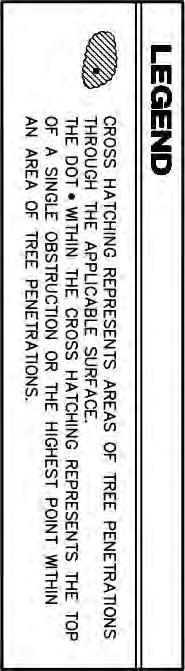

153 FIGURE AIRSPACE PLAN CRYSTAL RIVER AIRPORT CITRUS COUNTY, FLORIDA MASTER PLAN UPDATE
154 This page intentionally left blank.
155 Section 6 Airport Layout Plans Compliance with Part 77 surfaces at the Airport is enforced through Section 7500-Airport and Adjacent Land Use Controls of the Citrus County Land Development Code and those of adjacent political jurisdictions. The City of Crystal River has annexed a considerable amount of land west of the Airport into city limits. Therefore, it is recommended that the City of Crystal River adopt height zoning to compliment the County Height Zoning in the Land Development code. This will ensure that protection of the airport s approaches is maintained in the future. 6.4 TERMINAL AREA PLAN The terminal area plan (see Figure 6.4-1) focuses on siting facilities that were identified in the Facility Requirement section as being needed to serve projected demand during the next twenty years. The primary items include a proposed building for flight training, additional T-hangars and conventional hangars, as well as additional aircraft parking apron. A flight training building is proposed immediately east of the existing fixed base operator (FBO) hangar. Site parking can be provided west of the building and can serve the FBO and the proposed flight training building. This additional parking should provide approximately 22 spaces. Two additional rows of T-hangars (10-units each) are shown on the Terminal Area Plan immediately south of the existing 10-unit county owned T-hangars. The existing utilities (electric, water and sewer) and the water retention pond in this area were designed to accommodate these additional T-hangars. Therefore, development costs will primarily be limited to building and paving costs. The Facility Requirements section projects a demand for up to 30 additional T-hangar units during the study period. Therefore, a third 10-unit row of T-hangars is proposed east of the existing T-hangar automobile parking area. Construction of these T-hangars at this site would maximize the potential use of the existing automobile parking area. In addition to T-hangars, the Facility Requirement section estimates a demand for up to four additional conventional hangars. The Terminal Area Plan depicts the proposed location for two larger hangars directly across from the two existing hangars located south of North Lindbergh Drive. These hangars should accommodate a large twinengine or small jet aircraft. Although the Facility Requirements section estimates a demand for up to four additional conventional hangers, County personnel indicated a preference to provide one large conventional hangar (80 by 80 ) in lieu of two of those hangars. The proposed location for this hangar is immediately west of Hangar C and south of Hangar B. This site offers the advantages of existing taxilane access and proximity to existing utilities and the FBO s services. Although existing aircraft parking apron meets existing demand, a need for up to 1,800 square yards (SY) of aircraft parking was identified in the long-term. This equates to approximately 5 additional tie-down spaces using an allocation of 360 SY per aircraft parking position. No suitable location exists for additional apron in the existing terminal area. Therefore, The Terminal Area Plan proposes providing additional apron east of the county owned hangars in a configuration that would allow it to be reused as access to, and apron for, future hangars if the demand for apron changes in the future. 6-9 Crystal River Airport Master Plan Update
156


157 FIGURE TERMINAL AREA PLAN CRYSTAL RIVER AIRPORT CITRUS COUNTY, FLORIDA MASTER PLAN UPDATE
158 This page intentionally left blank.
159 Section 6 Airport Layout Plans The construction of a self-fueling facility is shown on the Terminal Area Plan adjacent to the exiting fuel farm. 6.5 LAND USE DRAWING The Land Use Drawing depicts how airport property is currently used and how it will be used in the future. It also shows the current use of land around the perimeter of the Airport. The drawing is depicted on Sheet 9 of the ALP drawing set and Figure Land use categories are described in the following paragraphs ON-AIRPORT LAND USE Land within airfield operational areas, safety areas, object free areas and the RPZs is reserved for airfield use. Land reserved for terminal area includes the present terminal area east of Runway and south of North Lindbergh Drive, as well as the land north of Runway 9-27 and south of Bicentennial Park. The majority of land within the leasehold of the Florida National Guard (FNG) is reserved for institutional use with the exception of property that falls within the Runway 9-27 object free area. The majority of the remaining property is classified as open space. This includes land that contains wetlands as well as the land south of Runway 9-27 that is not needed for development within the study timeframe. A summary of the Airport s existing land use by category is provided in Table As the table indicates, the majority of airport property is consumed by the airfield. Aviation related land use is the next largest use of airport property followed by the FNG. Quantities indicated in the table were calculated on the basis of computer-aided drafting (CAD) delineations and should be considered approximations. Table On-Airport Land Use Land Use Quantity (Acres) Percent of Airport Property Airfield % Terminal Area % Institutional % Open Space % TOTAL % Source: URS, OFF-AIRPORT LAND USE Off-airport land uses surrounding the Airport consist of a mixture of residential, commercial, industrial, governmental, recreational, and vacant land uses. Residential land uses are located north, east and west of the Airport. Commercial land uses are concentrated along the US Highway 19 corridor and along West Venable Street. Recreational land uses consist of Bicentennial Park to the north and Seven Rivers Golf Course to the northeast. Several large tracts of vacant land use exist south of the Airport Crystal River Airport Master Plan Update
160


161 FIGURE LAND USE DRAWING MASTER PLAN UPDATE CITRUS COUNTY, FLORIDA CRYSTAL RIVER AIRPORT
162 This page intentionally left blank.
163 Section 6 Airport Layout Plans 6.6 AIRPORT PROPERTY MAP / EXHIBIT A A new Airport Property Map / Exhibit A was prepared by county personnel and is shown in Figure The drawing depicts the various parcels that comprise the Airport, as well as who the parcel was acquired from, the date of acquisition, parcel size, and how the parcel was acquired. Existing easements are also depicted on the drawing. The property map also depicts planned land acquisition. Parcels proposed for acquisition include two commercial properties on the east side of US Highway 19 that are located within the RPZ on the north end of Runway 18-36, as well as one parcel along North Lindbergh Drive that contains a residence. This parcel is also located inside the RPZ on the north end of Runway Acquisition of these three parcels would enable the displaced threshold on Runway 18 to be eliminated and would improve the Airport s compliance with FAA guidance land use guidance within RPZs. One additional parcel is recommended for acquisition at the east end of Runway This parcel consists of 3.2 acres located at the east end of the current airport property line. This property will be needed to control land use in the RPZ at the east end of Runway 9-27 after he proposed runway extension of 645 feet. This land is currently part of the Seven River Golf Course and consists primarily of forested areas. FAA guidance recommends that Airport sponsors control all land within the limits of the RPZ. In cases where ownership is not practicable, the FAA then recommends that Airport sponsors maintain the RPZ clear of all facilities supporting incompatible activities. Acquisition of the recommended parcels would decrease existing operational constraints on Runway and would improve land use compatibility. The acquisition of avigation easements is recommended for property north of Godfrey Lane which is inside the RPZ at the north end of Runway The purpose of this easement would be to maintain compatible land use and ensure that future structure heights are consistent with airspace surface limitations Crystal River Airport Master Plan Update
164


165 FIGURE AIRPORT PROPERTY MAP / EXHIBIT "A" CRYSTAL RIVER AIRPORT CITRUS COUNTY, FLORIDA MASTER PLAN UPDATE
166 This page intentionally left blank.
167 Section 7 Facilities Implementation Plan SECTION 7 FACILITIES IMPLEMENTATION PLAN 7.1 INTRODUCTION This section identifies the capital improvement projects that comprise the development plans presented in the preceding section. Projects were identified on the basis of the following factors: safety, adherence to Federal Aviation Administration (FAA) design standards, capacity requirements and operational demands, as well as the priorities of airport tenants and Citrus County. The ultimate implementation of projects will be decided on the basis of many factors including funding availability, required environmental or other approvals, and the respective business decisions by the Airport Advisory Board (AAB) and tenants. This section also provides conceptual cost estimates for all projects (in 2017 dollars). No escalation factors were applied to project costs. This methodology allows project costs to be escalated on the basis of actual escalation factors from 2017 at the time they are initiated. The cost estimates include construction costs and program costs. Construction costs include all physical items and labor. Program costs include design fees, construction management, change order contingency, design services during construction, geotechnical fees, environmental costs and survey fees. Details of the cost estimates are provided in Appendix D. Staging periods for these projects were established as follows: Short-Term (2018 to 2022), Intermediate-Term (2023 to 2027), and Long-Term (2028 and beyond). The ultimate timing of projects will be determined on the basis of operational demand, funding availability, environmental approvals, and tenant and County priorities. 7.2 SHORT-TERM PROJECTS Project priorities in the short-term include safety-related items such as clearing obstructions from both ends of Runway 9-27 and the approach to Runway 36 as well as providing revenue generating facilities such as self-serve fueling capability and additional T-hangars. Short-Term projects are described in the following paragraphs and are illustrated (where possible) in Figure The estimated costs associated with these projects are shown in Table Crystal River Airport Master Plan Update
168
169 FIGURE SHORT - TERM PROJECTS CRYSTAL RIVER AIRPORT CITRUS COUNTY, FLORIDA MASTER PLAN UPDATE
170 This page intentionally left blank.
171 Section 7 Facilities Implementation Plan Project Number Table Short-Term (2018 to 2022) Project Cost Estimates Project Name Estimated Cost (2017 Dollars) S-1 Clear Obstructions in Runway 9-27 Approaches $647,000 S-2 Relocate Segmented Circle and Wind Cone $26,000 S-3 Displace Runway 9 Landing Threshold 200 Feet $466,000 S-4 Rehabilitate Runway 9-27 $2,777,000 S-5 Construct T-Hangars (Phase 2-10 Units) $1,855,000 S-6 Clear Obstructions North of Army National Guard Facilities $46,000 S-7 Clear Obstructions in Runway 36 Approach $312,000 S-8 Wildlife Site Visit $10,000 S-9 Construct Self-Serve Fueling Facility $195,000 S-10 Replace Airport Beacon $102,000 S-11 Construct Flight Training Building $2,028,000 S-12 Construct T-Hangars (Phase 3-10 Units) $2,086,000 S-13 Prepare Environmental Assessment for Extension of Runway 9-27 $250,000 Source: URS using cost estimates prepared by AID, TOTAL $10,800, CLEAR OBSTRUCTIONS IN RUNWAY 9-27 APPROACHES This project consists of clearing or lighting all existing obstructions to the Runway 9 and Runway 27 approach surface including trees, electrical power poles, light poles and signs. Power lines along US Highway 19 that are obstructions will require relocation underground and need to be coordinated with the power line owner. The purpose of this project is to provide clear approach surfaces in accordance with FAA design standards RELOCATE SEGMENTED CIRCLE AND WIND CONE The existing segmented circle and wind cone are located west of Runway and north of Runway 9-27 and is inside the Runway Object Free Area (ROFA) for both runways. FAA design standards specify that these navigational aids (NAVAIDs) should be located outside of the Runway Safety Area (RSA) and the ROFA. This project consists of relocating these items to a site east of the Automated Weather Observing System (AWOS) to meet design standards. 7-5 Crystal River Airport Master Plan Update
172 Section 7 Facilities Implementation Plan DISPLACE RUNWAY 9 LANDING THRESHOLD 200 FEET This project is needed as a result of the proposed widening of US Highway 19 which will introduce an obstruction into the approach surface to Runway 9. The adverse impact of this project must be mitigated by displacing the Runway 9 landing threshold 200 feet. This project consists of all the actions required to complete the displacement. This includes changes to runway markings and lighting, relocating the Runway End Identifier Lights (REILs) and installing a new Precision Approach Path Indicator (PAPI) in the required location. As noted in the Facility Requirement section, the existing PAPI on the approach end of Runway 9 needs to be replaced due to its age and condition. This project will also include the coordination required to revise the existing global positioning satellite (GPS) approach to Runway REHABILITATE RUNWAY 9-27 This project consists of constructing a pavement overlay on Runway 9-27 along its 4,555-foot length to improve the pavement condition. According to the June 2015, District 7 Statewide Airfield Pavement Management Program Report the runway segments at Crystal River Airport (CGC) had Pavement Condition Index (PCI) values of 64, 66, 68 and 69. The segments of adjoining taxiway inside the RSA had PCI values of 40, 56, 61 and 66. These values represent visual observations from 2014 and will have incurred additional years of deterioration prior to their rehabilitation. The rehabilitation of Runway 9-27 is recommended by the Florida Department of Transportation (FDOT) Pavement Management Study (PMS) CONSTRUCT T-HANGARS (PHASE 2 10 UNITS) The Facility Requirement section estimates a demand for up to 30 additional T-hangar units at the Airport during the study period. This project consists of the construction of a 10-unit T- Hangar building and associated taxilanes south of the existing county owned T-hangars. This site was originally designed to accommodate additional T-hangars and already provides the required grading, utilities and drainage CLEAR OBSTRUCTIONS NORTH OF ARMY NATIONAL GUARD FACILITIES The purpose of this project is to clear a stand of trees (approximately 2.7 acres) that penetrates the ROFA and the Part 77 Transitional Surface of Runway These trees are located south of Runway 9-27 and north of the Florida National Guard (FNG) facilities and should be cleared to achieve compliance with design standards CLEAR OBSTRUCTIONS IN RUNWAY 36 APPROACH This project consists of clearing approximately 18 acres of tall trees south of West Venable Street that are within the Runway Protection Zones (RPZ) for Runway 36. These trees are obstructions to the Runway 36 approach surface and are the reason why the landing threshold for Runway 36 is currently displaced 819 feet. Removal of these trees would bring the approach in conformance with design standards and would allow the displaced threshold on 7-6 Crystal River Airport Master Plan Update
173 Section 7 Facilities Implementation Plan Runway 36 to be reduced to a distance of approximately 465 feet. This would improve the safety and efficiency of the runway CONDUCT WILDLIFE SITE VISIT A wildlife site visit is recommended to quickly evaluate and mitigate potential wildlife hazards on the Airport and to determine whether a Wildlife Hazard Assessment is necessary. The visit will consist of a Qualified Airport Wildlife Biologist collecting and compiling information on the Airport's wildlife hazard history, including documented and suspected wildlife hazards, habitat attractants, control activities, airport operations procedures, communications of hazards, and aircraft operations and scheduling. The site visit will be conducted over a period of one to two days during which the Biologist will evaluate the habitat on and surrounding the Airport and records direct or indirect wildlife observations; and current wildlife management activities and airport wildlife strike data, if any CONSTRUCT SELF-SERVE FUELING FACILITY The construction of self-serve fueling facility was identified in the Inventory and Facility Requirements sections as a desired item in order to provide access to fuel during hours that the fixed base operator (FBO) is closed. This project consists of the installation of the required pumps, equipment and lighting needed to provide a properly equipped self-serve fuel facility adjacent to the existing fuel farm. This area presently provides adequate apron and maneuvering space for aircraft to access such a facility REPLACE AIRPORT BEACON The performance of the existing airport beacon is compromised by tall trees located west of the FBO. As noted in previous sections, the beacon is difficult to see from points northwest of the Airport due to the obscuring effect of surrounding trees. This project consists of installing a new beacon on a 75-foot tower at a site immediately south of the existing tower CONSTRUCT FLIGHT TRAINING BUILDING The Facility Requirements section noted a need for additional terminal space to accommodate the flight training services that currently occurs at the Airport. This project consists of the construction of a 5,000 square foot building for this purpose near the current FBO facility. This project also includes the construction of automobile parking to accommodate this facility and the parking requirements CONSTRUCT T-HANGARS (PHASE 3 10 UNITS) This project consists of constructing an additional 10-unit T-Hangar building and associated taxilanes south of the existing county owned T-hangars and the Phase 1 T-hangars proposed in this Capital Improvement Plan (CIP). This site was originally designed to accommodate additional T-hangars and already provides the required grading, utilities and drainage. 7-7 Crystal River Airport Master Plan Update
174 Section 7 Facilities Implementation Plan PREPARE ENVIRONMENTAL ASSESSMENT FOR EXTENSION OF RUNWAY 9-27 This project consists preparing an Environmental Assessment (EA) in accordance with the requirements of the National Environmental Policy Act of 1969 (NEPA). The EA will address the proposed extension of Runway 9-27 by 645 feet to the east. The EA will also address projects such as land acquisition and roadway changes that are needed to facilitate the runway extension. The EA should be prepared in accordance with guidance presented in FAA Order E Environmental Impacts: Policies and Procedures and FAA Order A NEPA Implementing Instructions for Airport Actions. 7.3 INTERMEDIATE-TERM PROJECTS Project priorities during the Intermediate-Term include a series of projects that would enable the extension of Runway This includes land acquisition and the construction of roadway improvements. Also included in the Intermediate-Term is the acquisition of properties that would allow for compliance with FAA land use guidance within the Runway 18 RPZ and a reduction of the displacement to the Runway 18 landing threshold. Intermediate-Term projects are described in the following paragraphs and are illustrated (where possible) in Figure The estimated costs associated with these projects are shown in Table Table Intermediate-Term (2023 to 2027) Project Cost Estimates Project Number Project Name Estimated Cost (2017 Dollars) I-1 Acquire Property in Approach to Runway 27 $61,000 I-2 Construct Roadway and Sidewalk Improvements $1,012,000 I-3 Construct 645-Foot Extension on East End of Runway 9-27 $4,042,000 I-4 Remark Airfield Pavements $325,000 I-5 Acquire Properties in Runway 18 RPZ $1,474,000 I-6 Acquire Avigation Easement in Runway 18 RPZ $1,618,000 I-7 Clear Obstructions in Approach to Runway 18 $55,000 TOTAL $8,587,000 Source: URS using cost estimates prepared by AID, ACQUIRE PROPERTY IN APPROACH TO RUNWAY 27 This project consists of acquiring approximately 3.2 acres of land that will be within the future RPZ on the east end of Runway 9-27 after it is extended 645 feet to the east. This property is currently owned by the Seven Rivers Golf and Country Club and consists primarily of forested land except for a portion near the existing driving range that appears to contain a practice putting green and sand trap. Acquisition of this property may require relocation of these facilities. 7-8 Crystal River Airport Master Plan Update
175 FIGURE INTERMEDIATE - TERM PROJECTS CRYSTAL RIVER AIRPORT CITRUS COUNTY, FLORIDA MASTER PLAN UPDATE
176 This page intentionally left blank.
177 Section 7 Facilities Implementation Plan CONSTRUCT ROADWAY AND SIDEWALK IMPROVEMENTS This project consists of several roadway changes that must be implemented prior to the proposed extension of Runway These changes include removing the portion of North Golf Course Drive that extends from the Airport s north boundary to its south boundary and constructing a Cul de Sac at the roadway s termination at the Airport s north boundary. A new segment of roadway (approximately 1,700 linear feet) is proposed north of the Airport to connect North Golf Course Drive to West Bicentennial Park Drive. This segment of roadway will provide an alternate means of access for residents along North Golf Course Drive north of the Airport. The proposed alignment for the new segment of roadway segment will begin on Airport property and then proceed on County owned property to West Bicentennial Park Drive which connects to North Lindbergh Drive. The Facility Requirements section noted that sidewalks are a desired item for safety reasons along North Lindbergh Drive due to its access to Bicentennial Park and the volume of pedestrians, bicyclists and skate boarders that use this road. Therefore, it is recommended that sidewalks be constructed along the new segment of roadway and continue along North Lindbergh Drive to address this safety issue CONSTRUCT 645-FOOT EXTENSION ON EAST END OF RUNWAY 9-27 This project consists of constructing a 645-foot extension on the east end of Runway 9-27 along with an extension of Taxiway A. This extension is proposed to accommodate the runway length requirements of the design aircraft when 500 or more annual operations can be documented. The extension includes all associated lighting and marking changes along with the required revision to the published instrument approach REMARK AIRFIELD PAVEMENTS Pavement markings degrade over time as a result of sunshine and other weather phenomena that fade paint color and loosen adherence to pavements. Consequently, remarking of pavements is necessary to ensure that markings remain visible to pilots and continue to provide the required information. This project consists of remarking Runway 9-27, Taxiways A and B and all lead-in taxilanes ACQUIRE PROPERTIES IN RUNWAY 18 RPZ This project consists of acquiring two parcels of land within the RPZ on the north end of Runway The first parcel consists of approximately 0.72 acres and contains a single-family residence. The second parcel consists of approximately 0.69 acres of commercial land use along the east side of US Highway 19. This parcel currently contains two structures that contain multiple businesses. The purpose of this property acquisition is to bring the RPZ into compliance with FAA land use guidance which specifies that the RPZ should be owned by the Airport, where feasible, and 7-11 Crystal River Airport Master Plan Update
178 Section 7 Facilities Implementation Plan cleared of all incompatible objects and activities. Acquisition of this property would also facilitate the removal of obstructions to the Runway 18 approach surface. These obstructions are the reason why the Runway 18 landing threshold is currently displaced by 192 feet. Removal of these obstructions would allow this displacement to be eliminated ACQUIRE AVIGATION EASEMENT IN RUNWAY 18 RPZ This project consists of acquiring avigation easements for two properties located inside the Runway 18 RPZ north of Godfrey Lane. These parcels currently contain commercial structures. Acquiring avigation easements for these properties would provide control over potential future land uses and eliminate the potential for future obstructions to the Runway 18 approach surface CLEAR OBSTRUCTIONS IN APPROACH TO RUNWAY 18 This project consists of removing on-airport obstructions to the Runway 18 approach surface. Two groups of trees are currently located in the RPZ and within the approach surface to Runway 18. The first group consists of a few trees at the northwest corner of airport property. The second group consists of a larger area of trees (approximately 0.8 acres) along the west side of North Lindbergh Drive. This project consists of removing and/or topping these trees, as needed, to clear them from the Runway 18 approach surface. 7.4 LONG-TERM PROJECTS Project priorities in the long-term include the continued development of hangar facilities and the rehabilitation of facilities that will likely be reaching the end of their useful lives. Long-Term projects are described in the following paragraphs and are illustrated (where possible) in Figure The estimated costs associated with these projects are shown in Table Table Long-Term (2028 and Beyond) Project Cost Estimates Estimated Cost (2017 Dollars) Project Number Project Name L-1 Construct Two Conventional Hangars $1,356,000 L-2 Reconfigure Taxiway A Entrance to Runway 9 $380,000 L-3 Update Airport Master Plan $282,000 L-4 Construct T-Hangars (Phase 4-10 Units) $3,031,000 L-5 Rehabilitate Taxiway A $1,426,000 L-6 Rehabilitate Hangar Taxilanes $365,000 L-7 Rehabilitate Runway 9-27 Lighting $769,000 L-8 Construct Large Conventional Hangar $1,098,000 L-9 Install Airport Signage at US 19 and Godfrey Road $72,000 L-10 Replace Airfield Security Fencing $1,919,000 L-11 Construct Itinerant Apron $460,000 TOTAL $1,1158,000 Source: URS using cost estimates prepared by AID, Crystal River Airport Master Plan Update
179 FIGURE LONG - TERM PROJECTS CRYSTAL RIVER AIRPORT CITRUS COUNTY, FLORIDA MASTER PLAN UPDATE
180 This page intentionally left blank.
181 Section 7 Facilities Implementation Plan CONSTRUCT TWO CONVENTIONAL HANGARS In addition to a demand for additional T-Hangars, the Facility Requirements section projects an additional demand for conventional hangars. This project would satisfy a portion of that demand by constructing two additional conventional hangars that are the same size (width of 55 feet and depth of 60 feet) as the two large County-owned units north of Taxiway A. It is proposed that these hangars be constructed on the opposite side of the apron that currently serves the two existing hangars. This would maximize use of the existing taxilane and minimize development costs RECONFIGURE TAXIWAY A ENTRANCE TO RUNWAY 9 This project will consist of reconstructing the portion of Taxiway A at the west end of Runway This portion of the taxiway was not reconstructed when Taxiway A was relocated to its current location due to the presence of a nearby water retention pond. Current FAA design standards call for the removal of existing taxiway pavement, where needed, to correct confusing layouts and enhance safety by avoiding runway incursions. The design standards call for right angle intersections between taxiways and runways to provide pilots with the best visibility in both directions. The proposed reconfiguration of Taxiway A will provide a standard 90 degree turn to the approach end of Runway UPDATE AIRPORT MASTER PLAN FAA guidance recommends that airport sponsors update their master plan when needed to address changes in demand, critical aircraft or other factors that require a strategic review. This project consists of a full master plan update in the 10 to 20-year range CONSTRUCT T-HANGARS (PHASE 4 10 UNITS) This project consists of constructing a fourth 10-unit T-Hangar building and associated taxilanes east of the existing county owned T-hangars. Unlike the sites for Phase 2 and Phase 3 T- hangars, this site was not previously prepared for the installation of T-hangars and therefore will require all necessary development including grading, drainage and utilities REHABILITATE TAXIWAY A The FDOT 2015 PMS determined that Taxiway A pavements are currently in good condition and have PCI values ranging from 89 to 99. These values will decline over time and will reach a point where rehabilitation is required. This project will consist of rehabilitating Taxiway A pavements when needed. The need for this project will be based upon PCI values from future pavement management studies REHABILITATE HANGAR TAXILANES This project consists of rehabilitating the taxilanes leading to the shade hangars and the conventional hangar south of the FBO when needed in the long-term period Crystal River Airport Master Plan Update

182 Section 7 Facilities Implementation Plan REHABILITATE RUNWAY 9-27 LIGHTING Estimated useful life for edge lighting is 20 years. This project consists of replacing the edge lighting on Runway 9-27 when required by condition and operation CONSTRUCT LARGE CONVENTIONAL HANGAR The Facility Requirements section noted a demand for up to four larger individual hangars in addition to 30 T-Hangars. Rather than providing four separate conventional hangars, County personnel indicated a preference to provide one large conventional hangar (80 by 80 ) in lieu of two of those hangars. The proposed location for this hangar is immediately west of Hangar C and south of Hangar B. This site offers the advantages of existing taxilane access and proximity to existing utilities and the FBO services INSTALL AIRPORT SIGNAGE AT US 19 AND GODFREY ROAD Existing signage for the Airport consists of standard FDOT roadway signs (i.e., a green aircraft symbol with a directional arrow). This signage is not very prominent and does not present the name of the airport. This project consists of the creation and installation of a lighted airport sign that would present the name of the Airport along with other information specified by the County. Installation of this type of signage would provide a higher level of visibility and recognition for the Airport and would assist motorists on US 19 locate the entrance to the facility REPLACE AIRFIELD SECURITY FENCING Airport fencing is subject to deterioration over time as a result of weather, vegetative growth and other natural factors. This project consists of the replacement of existing fencing with new fencing in accordance with FAA requirements when needed based on condition CONSTRUCT ITINERANT APRON This project consists of the construction of additional apron and a connecting taxilane to Taxiway A. This apron is proposed to be constructed in a manner that would ultimately enable it to be used as apron for future hangars beyond the study period. 7.5 PROJECT FUNDING ELIGIBILITY Funding for projects identified in the preceding subsections consist of monies from three different sources. These sources include funding from the FAA in the form of grants from the 7-16 Crystal River Airport Master Plan Update
183 Section 7 Facilities Implementation Plan Airport Improvement Program (AIP), funding from the FDOT in the form of grants from the Florida Aviation Grant Program (FAGP) and local monies from Citrus County. Funding from all three of these sources is needed to implement the projects proposed in the preceding section AIRPORT IMPROVEMENT PROGRAM The two primary sources of AIP funding include entitlement funding and discretionary funding. Entitlement funding consists of a predetermined amount of funding available for airports using an established formula. This value is established through legislation passed by the US Congress and can change based upon legislative priorities, but currently is $150,000 per year for general aviation airports such as Crystal River. Projects proposed for AIP funding must enhance airport safety, capacity, security or environmental goals. Discretionary funding is based on project eligibility rankings and must compete with projects proposed at other airports. Therefore, proposed projects must rank high in order to successfully complete for those funds. Entitlement and discretionary grants may cover a range of 90 to 95 percent of eligible costs, based on statutory requirements. All projects seeking AIP funding must be depicted on an FAA approved Airport Layout Plan (ALP) THE FLORIDA AVIATION GRANT PROGRAM This program was established to fund projects relating to airport planning and capital improvements that address safety, security or capacity improvements, land acquisition, and economic development. When a project is funded by the FAA, FDOT may provide up to 80 percent of the remaining (non-federal) share of project costs for general aviation airports. For economic projects FDOT may provide up to 50 percent of the costs to build on-airport revenueproducing capital improvements. Consultation with FDOT District 7 personnel indicates that the district is currently limiting grants for hangar development to 50 percent of project cost LOCAL FUNDING Citrus County provides the matching share of funds for grants received from the FAA and FDOT. This can range from as little as 2 percent for projects that receive FAA and FDOT grants to as much as 50 percent for projects that are not eligible for Federal funding and for which FDOT has limited funding to 50 percent. Local monies are funded at the discretion of elected County officials and is not subject to formulas like Federal and State funding PROJECT ELIGIBILITY The eligibility of the projects identified in the preceding sections for FAA and FDOT grants is summarized in this section and presented in the following table. It is important to note that although the Airport is eligible for the funding percentages indicated it does not mean that the project will be funded at that amount. The Airport will still be subject to the funding limitations of entitlement and discretionary funding. Consequently, entitlement funds may need to be carried over for multiple years and/or combined with discretionary funding in order to attain sufficient 7-17 Crystal River Airport Master Plan Update
184 Section 7 Facilities Implementation Plan funds to undertake the project. Tables 7.5-1, and presents funding eligibility percentages for projects listed in the short, intermediate and long-term. A review of the projects identified in the preceding section with County staff indicated a desire to schedule each project by year in addition to terms. Tables 7.5-1, and also present the desired year of implementation for each project. Actual years of implementation will depend on funding availability Crystal River Airport Master Plan Update
185 Section 7 Facilities Implementation Plan Table Short-Term (2018 to 2022) Project Funding Eligibility Percentages and Amounts Project Project FAA FDOT Local Implementation Number Name % Amount % Amount % Amount Total Year* S-1 Clear Obstructions in Runway 9-27 Approaches 90% $582,300 8% $51,760 2% $12,940 $647, S-2 Relocate Segmented Circle and Wind Cone 90% $23,400 8% $2,080 2% $520 $26, S-3 Displace Runway 9 Landing Threshold 200 Feet 90% $419,400 8% $37,280 2% $9,320 $466, S-4 Rehabilitate Runway % $2,499,300 8% $222,160 2% $55,540 $2,777, S-5 Construct T-Hangars (Phase 2-10 Units) 0% - 80% $1,484,000 20% $371,000 $1,855, S-6 Clear Obstructions North of Armory 90% $41,400 8% $3,680 2% $920 $46, S-7 Clear Obstructions in Runway 36 Approach 90% $280,800 8% $24,960 2% $6,240 $312, S-8 Wildlife Site Assessment 90% $9,000 8% $800 2% $200 $10, S-9 Construct Self-Serve Fueling Facility 90% $175,500 8% $15,600 2% $3,900 $195, S-10 Replace Airport Beacon 90% $91,800 8% $8,160 2% $2,040 $102, S-11 Construct Flight Training Building 0% - 50% $1,014,000 50% $1,014,000 $2,028, S-12 Construct T-Hangars (Phase 3-10 Units) 0% - 50% $1,043,000 50% $1,043,000 $2,086, S-13 Prepare Environmental Assessment for 90% $225,000 8% $20,000 2% $5,000 $250, Extension of Runway 9-27 TOTAL $4,347,900 $3,927,480 $2,524,620 $10,800,000 Source: URS, * Implementation year subject to funding availability Crystal River Airport Master Plan Update
186 Section 7 Facilities Implementation Plan Table Intermediate-Term (2023 to 2027) Project Funding Eligibility Percentages and Amounts Project Project FAA FDOT Local Implementation Number Name % Amount % Amount % Amount Total Year* I-1 Acquire Property in Runway 27 Approach 90% $54,900 8% $4,880 2% $1,220 $61, I-2 Construct Roadway and Sidewalk Improvements 90% $910,800 8% $80,960 2% $20,240 $1,012, Construct 645-Foot Extension on East End of I-3 Runway % $3,637,741 8% $323,355 2% $80,839 $4,041, I-4 Remark Airfield Pavements 90% $292,500 8% $26,000 2% $6,500 $325, I-5 Acquire Properties in Runway 18 RPZ 90% $1,326,600 8% $117,920 2% $29,480 $1,474, I-6 Acquire Avigation Easement in Runway 18 RPZ 90% $1,456,200 8% $129,440 2% $32,360 $1,618, I-7 Clear Obstructions in Runway 18 Approach 90% $49,500 8% $4,400 2% $1,100 $55, TOTAL $7,728,241 $686,955 $171,739 $8,586,934 Source: URS, * Implementation year subject to funding availability. Table Long-Term (2028 and Beyond) Project Funding Eligibility Percentages and Amounts FAA FDOT Local Implementation % Amount % Amount % Amount Total Year* Project Number Project Name L-1 Construct Two Conventional Hangars % $678,000 50% $678,000 $1,356, L-2 Reconfigure Taxiway A Entrance to Runway 9 90% $342,000 8% $30,400 2% $7,600 $380, L-3 Update Airport Master Plan 90% $253,800 8% $22,560 2% $5,640 $282, L-4 Construct T-Hangars (Phase 4-10 Units) % $1,515,500 50% $1,515,500 $3,031, L-5 Rehabilitate Taxiway A 90% $1,283,400 8% $114,080 2% $28,520 $1,426, L-6 Rehabilitate Hangar Taxilanes 90% $328,500 8% $29,200 2% $7,300 $365, L-7 Rehabilitate Runway 9-27 Lighting 90% $692,100 8% $61,520 2% $15,380 $769, L-8 Construct Large Conventional Hangar % $549,000 50% $549,000 $1,098, L-9 Install Airport Signage at US 19 and Godfrey Road 90% $64,800 8% $5,760 2% $1,440 $72, L-10 Replace Airfield Security Fencing 90% $1,727,100 8% $153,520 2% $38,380 $1,919, L-11 Construct Itinerant Apron 90% $414,000 8% $36,800 2% $9,200 $460, TOTAL $5,105,700 $3,196,340 $2,855,960 $11,158,000 Source: URS, * Implementation year subject to funding availability Crystal River Airport Master Plan Update
187 APPENDIX A Acronyms and Abbreviations
188
189 APPENDIX A ACRONYMS AND ABBREVIATIONS ACRONYM DEFINITION AAB Airport Advisory Board AAC Aircraft Approach Category AC Advisory Circular ACRP Airport Cooperative Research Program ADG Airplane Design Group AFM Airplane Flight Manual AGL Above Ground Level AICP Airport Capital Improvement Program AIP Airport Improvement Program ALP Airport Layout Plan APM Airport Planning Manual ARC Airport Reference Code ASV Annual Service Volume ATA Air Traffic Airspace AWOS Automated Weather Observing System BA Biological Assessment BKV Brooksville-Tampa Bay Regional Airport CAD Computer-Aided Drafting CAG Crystal Aero Group CFASPP Continuing Florida Aviation System Planning Process CFR Code of Federal Regulations CGC Crystal River Airport CH High Intensity Commercial CIP Capital Improvement Program Comp Plan Citrus County Comprehensive Plan CRAS Cultural Resources Assessment Survey CTAF Common Traffic Advisory Frequency Cw Weighted Hourly Capacity CWA Clean Water Act CY Calendar Year db Decibel DHR Division of Historic Resources DNL Day-Night Level EA Environmental Assessment EDC Economic Development Council EO Executive Order ERP Environmental Resource Permit ESA Endangered Species Act of 1973 F.A.C. Florida Administrative Code FAA Federal Aviation Administration FAGP Florida Aviation Grant Program FANG Florida Army National Guard FASP Florida Aviation System Plan FBO Fixed Base Operator FDOT Florida Department of Transportation A-1 Crystal River Airport Master Plan Update
190 ACRONYM DEFINITION FEMA Federal Emergency Management Agency FHWA Federal Highway Administration FIRM Flood Insurance Rate Map FLUCFCS Florida Land Use, Cover and Forms Classification System FMSF Florida Master Site File FONPA Finding of No Practicable Alternative FWC Florida Fish and Wildlife Conservation Commission FWS U.S. Fish and Wildlife Service FY Fiscal Year GPS Global Positioning System IFR Instrument Flight Rules IMC Instrument Meteorological Conditions lbs Pounds MIRL Medium Intensity Runway Lights MITL Medium Intensity Taxiway Lights MOAs Military Operations Areas msl Mean Sea Level MTOW Maximum Takeoff Weights NAS National Airspace System NAVAIDs Navigational Aids NEPA National Environmental Policy Act NFDC National Flight Data Center NHPA National Historic Preservation Act NPDES National Pollutant Discharge Elimination System NPIAS National Plan of Integrated Airport Systems NRHP National Register of Historic Places OCS Obstacle Clearance Surface OFZ Obstacle Free Zones PAPIs Precision Approach Path Indicators PCI Pavement Condition Index PD&E Project Development and Environmental PMS Pavement Management Study POH Pilot s Operating Handbook RDC Runway Design Code REILS Runway End Identifier Lights RHA Rivers and Harbors Act of 1899 RNAV Area Navigation ROFA Runway Object Free Areas RPZ Runway Protection Zones RSA Runway Safety Areas SHPO State Historic Preservation Office SOS Siren Operated Sensors SWFWMD Southwest Florida Water Management District SY Square Yards TAF Terminal Area Forecast TFMSC Traffic Flow Management System Counts TRB Transportation Research Board TSA Taxiway Safety Area USACE U.S. Army Corps of Engineers A-1 Crystal River Airport Master Plan Update
191 ACRONYM USC VA VFR VIS vmc DEFINITION United States Code Veteran Affairs Visual Flight Rule Visual Visual Meteorological Conditions A-1 Crystal River Airport Master Plan Update
192
193 APPENDIX B Cost Estimates for Runway Alternatives
194

195 Crystal River Airport Capital Improvement Program Rough Order of Magnitude Cost Estimate Project Alternative 1: Displace Runway 9 200' Date: November 17, 2015 No. Description Quant Unit Unit Price Total Cost 1 Mobilization 1.0 LS $ 45, $ 45, Maintenance of Air Operations Traffic 1.0 LS $ 25, $ 25, Temporary Stormwater Pollution Prevention, Erosion and Siltation Control 1.0 LS $ 5, $ 5, Miscellaneous Clearing and Grubbing 0.5 AC $ 9, $ 4, Tree (80.0 Feet) - individual tree clearing 1.0 EA $ 1, $ 1, Light Pole (42.0 Feet) - Replace with 15' pole 1.0 EA $ 5, $ 5, Power Pole (44.0 Feet) - Remove 1.0 EA $ 1, $ 1, Tree (41.0 Feet) - individual tree clearing 1.0 EA $ 1, $ 1, Light Pole (38.0 Feet) - Replace with 15' pole 1.0 EA $ 5, $ 5, Additional Trees - Close to Surface at time of estimate, assumed to exceed when construction begins. 8.0 EA $ 2, $ 16, Tree (44.0 Feet) - individual tree clearing 1.0 EA $ 2, $ 2, Power Pole (32.0 Feet) - Remove 1.0 EA $ 1, $ 1, Tree (84.0 Feet) within Future Disp. Threshold 1.0 EA $ 2, $ 2, Sign on Pole within Future Disp. Threshold 1.0 EA $ 7, $ 7, Relocate Overhead power lines to underground power lines (poles 13 to 21), 16 Additional 15' Light Poles, luminaires and electrical connections for Parking Lot (meet required lumens) 1,000.0 LF $ $ 175, EA $ 5, $ 55, Pavement Marking 37,500.0 SF $ 1.75 $ 65, Security Fencing 1,200.0 LF $ $ 30, Wind Cone and Segmented Circle - Remove & Relocate 1.0 LS $ 10, $ 10, Relocate Threshold Lights, Incl. Cable and duct 1.0 EA $ 37, $ 37, Adjust Runway Lighting 1.0 LS $ 25, $ 25, PAPI- Relocate Existing, including Flight Check 1.0 EA $ 8, $ 8, REIL- Relocate Existing 2.0 EA $ 4, $ 8, Sub-Total $ 538, Contingency (25%) $ 134, Total Construction Cost $ 673, Design & Bidding Services (5.5%) $ 37, Permitting Allowance (0.75%) $ 5, Topographic Survey Estimate $ 12, Geotechnical Investigation Estimate. $ - Utility Location Service Estimate $ 10, Construction Administration (4%) $ 26, Quality Assurance Material Testing Allowance Estimate $ 12, Total Cost Budget (2015, 4TH Qtr.) $ 776, Rounded Total Cost Budget (2015, 4th Qtr.) $ 780,000 Page 1
196 Crystal River Airport Capital Improvement Program Rough Order of Magnitude Cost Estimate Project Alternative 1a: Extend RW ' and Clear Obstructions Date: July 20, 2016 No. Description Quant Unit Unit Price Total Cost 1 Mobilization 1 LS $ 189, $ 189, Maintenance of Landside and Air Operations Traffic 1 LS $ 30, $ 30, Runway 27 End tems 3 Turf Stripping 25,000 SY $ 1.00 $ 25, Clearing and Grubbing 6 AC $ 9, $ 55, Obstruction Clearing- Select Trees- RPZ outside of ROFA/TOFA 13 AC $ 2, $ 25, Muck Excavation 10,000 CY $ 8.00 $ 80, Embankment- Borrow (offsite) 19,000 CY $ $ 190, Subgrade Compaction (12" Depth) 3,700 SY $ 8.00 $ 29, Temporary Stormwater Pollution Prevention, Erosion and Siltation Control 1 LS $ 50, $ 50, Lime Rock Base Course (8" - Full Strength) 3,700 SY $ $ 44, Bituminous Surface Course (4") 814 TN $ $ 93, Bituminous Prime Coat 1,295 GAL $ 2.50 $ 3, Bituminous Tack Coat 370 GAL $ 2.50 $ Pavement Marking 30,000 SF $ 1.75 $ 52, Drainage Improvements 1 LS $ 100, $ 100, Airfield Electrical Improvements 1 LS $ 110, $ 110, Access Road - South Hammerhead Pavements, Markings, Signage 500 SY $ $ 22, Access Road- North Road Cul-De-Sac Pavements, Markings, Signage 700 SY $ $ 31, Access Road- Extension Preparation 1.5 AC $ 5, $ 8, Access Road- Earthwork 2,500.0 CY $ $ 25, Access Road- Extension Pavements, Markings, Signage 3,500 SY $ $ 157, Sinkhole Stabilization - Runway 25,000 SF $ 8.25 $ 206, Security Fencing 1,500 LF $ $ 37, New Manual Gates 2 EA $ 3, $ 6, PAPI- New, Including Flight Check 1 EA $ 37, $ 37, REIL- Relocate Existing 1 EA $ 4, $ 4, Relocate Threshold Lights, Incl. Cable and duct 1.0 EA $ 22, $ 22, Sodding 3,000 SY $ 4.00 $ 12, Grassing 5 AC $ 1, $ 7, Topsoil (3" Thick) 150 CY $ 5.00 $ Runway 9 Items 32 Miscellaneous Clearing and Grubbing 0.5 AC $ 9, $ 4, Tree (80.0 Feet) - individual tree clearing 1.0 EA $ 1, $ 1, Light Pole (42.0 Feet) - Replace with 15' pole 1.0 EA $ 5, $ 5, Power Pole (44.0 Feet) - Remove 1.0 EA $ 1, $ 1, Tree (41.0 Feet) - individual tree clearing 1.0 EA $ 1, $ 1, Light Pole (38.0 Feet) - Replace with 15' pole 1.0 EA $ 5, $ 5, Additional Trees - Close to Surface at time of estimate, assumed to exceed when construction begins. 8.0 EA $ 2, $ 16, Tree (44.0 Feet) - individual tree clearing 1.0 EA $ 2, $ 2, Power Pole (32.0 Feet) - Remove 1.0 EA $ 1, $ 1, Tree (84.0 Feet) within Future Disp. Threshold 1.0 EA $ 2, $ 2, Sign on Pole within Future Disp. Threshold 1.0 EA $ 7, $ 7, Page 1
197 Crystal River Airport Capital Improvement Program Rough Order of Magnitude Cost Estimate Project Alternative 1a: Extend RW ' and Clear Obstructions Date: July 20, Relocate Overhead power lines to underground power lines (poles 13 to 21), 45 Additional 15' Light Poles, luminaires and electrical connections for Parking Lot (meet required lumens) 1,000.0 LF $ $ 175, EA $ 5, $ 55, Pavement Marking 37,500.0 SF $ 1.75 $ 65, Security Fencing 1,200.0 LF $ $ 30, Wind Cone and Segmented Circle - Remove & Relocate 1.0 LS $ 10, $ 10, New Threshold Lights, Incl. Cable and duct 1.0 EA $ 37, $ 37, Adjust Runway Lighting (all) 1.0 LS $ 25, $ 25, PAPI- Relocate Existing, including Flight Check 1.0 EA $ 8, $ 8, REIL- Relocate Existing 1.0 EA $ 4, $ 4, Sub-Total $ 2,120, Contingency (25%) $ 530, Total Construction Cost $ 2,650, Design & Bidding Services (5.5%) $ 145, Legal Services Allowance (0.75%) $ 19, Permitting Allowance (0.75%) $ 19, Topographic Survey Estimate $ 25, Geotechnical Investigation Estimate. $ 20, Utility Location Service Estimate $ 5, Construction Administration (4%) $ 106, Construction Management $ 162, Quality Assurance Material Testing Allowance Estimate $ 25, Total Cost Budget (2015, 3rd Qtr.) $ 3,179, Property Acquisition to control Avigation Easement in RPZ 0.8 AC $ 75, $ 60, Wetland Mitigation (14.2 Acres) 7.0 CR $ 136, $ 952, Wetland Mitigation Design 1 LS $ 25, $ 25, Environmental Assessment 1 LS $ 200, $ 200, Rounded Total Cost Budget (2016, 2nd Qtr.) $ 4,420,000 Contingency includes: Floodplain Compensation Page 2
198 Crystal River Airport Capital Improvement Program Rough Order of Magnitude Cost Estimate Project Alternative 2: Extend RW ' Date: November 17, 2015 No. Description Quant Unit Unit Price Total Cost 1 Mobilization 1 LS $ 187, $ 187, Maintenance of Air Operations Traffic 1 LS $ 20, $ 20, Turf Stripping 86,127 SY $ 1.00 $ 86, Clearing and Grubbing 6 AC $ 9, $ 55, Obstruction Clearing- Select Trees- RPZ outside of ROFA/TOFA 12 AC $ 2, $ 23, Muck Excavation 10,868 CY $ 8.00 $ 86, Embankment- Borrow (offsite) 22,630 CY $ $ 226, Subgrade Compaction (12" Depth) 7,982 SY $ 8.00 $ 63, Temporary Stormwater Pollution Prevention, Erosion and Siltation Control 1 LS $ 50, $ 50, Lime Rock Base Course (8" - Full Strength) 7,639 SY $ $ 91, Bituminous Surface Course (4") 2,200 TN $ $ 253, Bituminous Prime Coat 2,676 GAL $ 2.50 $ 6, Bituminous Tack Coat 767 GAL $ 2.50 $ 1, Pavement Marking 39,125 SF $ 1.75 $ 68, Drainage Improvements 1 LS $ 125, $ 125, Airfield Electrical Improvements 1 LS $ 150, $ 150, Access Road - South Hammerhead 500 SY $ $ 22, Access Road- North Road Cul-De-Sac 700 SY $ $ 31, Access Road- Extension Preparation 1.5 AC $ 5, $ 8, Access Road- Earthwork 2,500.0 CY $ $ 25, Access Road- Extension Pavements 3,500 SY $ $ 157, Sinkhole Stabilization - Runway 25,000 SF $ 8.25 $ 206, Security Fencing 1,500 LF $ $ 37, New Manual Gates 2 EA $ 3, $ 6, PAPI- New, Including Flight Check 1 EA $ 37, $ 37, PAPI- Relocate Existing, including Flight Check 1 EA $ 4, $ 4, REIL- Relocate Existing 2 EA $ 2, $ 5, Sodding 7,778 SY $ 4.00 $ 31, Grassing 5 AC $ 1, $ 7, Topsoil (3" Thick) 650 CY $ 5.00 $ 3, Page 2
199 Crystal River Airport Capital Improvement Program Rough Order of Magnitude Cost Estimate Project Alternative 2: Extend RW ' Date: November 17, 2015 Sub-Total $ 2,078, Contingency (25%) $ 519, Total Construction Cost $ 2,597, Design & Bidding Services (5.5%) $ 142, Legal Services Allowance (0.75%) $ 19, Permitting Allowance (0.75%) $ 19, Topographic Survey Estimate $ 30, Geotechnical Investigation Estimate. $ 25, Utility Location Service Estimate $ 5, Construction Administration (4%) $ 103, Construction Management $ 162, Quality Assurance Material Testing Allowance Estimate $ 50, Total Cost Budget (2015, 3rd Qtr.) $ 3,156, Property Acquisition to control Avigation Easement in RPZ 2 AC $ 75, $ 150, Wetland Mitigation (14.2 Acres) 7.0 CR $ 136, $ 952, Wetland Mitigation Design 1 LS $ 25, $ 25, Environmental Assessment 1 LS $ 200, $ 200, Rounded Total Cost Budget (2015, 4th Qtr.) $ 4,490,000 Contingency includes: Floodplain Compensation Page 3
200 Crystal River Airport Capital Improvement Program Rough Order of Magnitude Cost Estimate Project Alternative 3: Extend RW ' Date: November 17, 2015 No. Description Quant Unit Unit Price Total Cost 1 Mobilization 1 LS $ 255, $ 255, Maintenance of Air Operations Traffic 1 LS $ 15, $ 15, Turf Stripping 18,940 SY $ 1.00 $ 18, Clearing and Grubbing 11 AC $ 9, $ 103, Obstruction Clearing- Select Trees- RPZ outside of ROFA/TOFA 6 AC $ 2, $ 11, Muck Excavation 28,420 CY $ 8.00 $ 227, Embankment- Borrow (offsite) 37,799 CY $ $ 377, Subgrade Compaction (12" Depth) 13,788 SY $ 8.00 $ 110, Temporary Stormwater Pollution Prevention, Erosion and Siltation Control 1 LS $ 50, $ 50, Lime Rock Base Course (8" - Full Strength) 13,195 SY $ $ 158, Bituminous Surface Course (4") 3,800 TN $ $ 437, Bituminous Prime Coat 4,620 GAL $ 2.50 $ 11, Bituminous Tack Coat 1,323 GAL $ 2.50 $ 3, Pavement Marking 41,354 SF $ 1.73 $ 71, Drainage Improvements 1 LS $ 150, $ 150, Airfield Electrical Improvements 1 LS $ 200, $ 200, Access Road - South Hammerhead 500 SY $ $ 22, Access Road- North Road Cul-De-Sac 700 SY $ $ 31, Access Road- Extension Preparation 1.5 AC $ 5, $ 8, Access Road- Earthwork 2,500.0 CY $ $ 25, Access Road- Extension Pavements 3,500 SY $ $ 157, Sinkhole Stabilization - Runway 25,000 SF $ 8.25 $ 206, Security Fencing 2,000 LF $ $ 50, New Manual Gates 2 EA $ 3, $ 6, PAPI- New, Including Flight Check 1 EA $ 37, $ 37, PAPI- Relocate Existing, including Flight Check 1 EA $ 4, $ 4, REIL- Relocate Existing 2 EA $ 2, $ 5, Sodding 13,169 SY $ 4.00 $ 52, Grassing 11 AC $ 1, $ 17, Topsoil (3" Thick) 2 CY $ 5.00 $ 8.75 Page 4
201 Crystal River Airport Capital Improvement Program Rough Order of Magnitude Cost Estimate Project Alternative 3: Extend RW ' Date: November 17, 2015 Sub-Total $ 2,824, Contingency (25%) $ 706, Total Construction Cost $ 3,530, Design & Bidding Services (5.5%) $ 194, Legal Services Allowance (0.75%) $ 26, Permitting Allowance (0.75%) $ 26, Topographic Survey Estimate $ 30, Geotechnical Investigation Estimate. $ 25, Utility Location Service Estimate $ 5, Construction Administration (4%) $ 141, Construction Management $ 162, Quality Assurance Material Testing Allowance Estimate $ 75, Total Cost Budget (2015, 3rd Qtr.) $ 4,216, Property Acquisition to control Avigation Easement in RPZ 2 AC $ 75, $ 150, Wetland Mitigation (14.2 Acres) 7.0 CR $ 136, $ 952, Wetland Mitigation Design 1 LS $ 25, $ 25, Environmental Assessment 1 LS $ 200, $ 200, Contingency includes: Floodplain Compensation Rounded Total Cost Budget (2015, 4th Qtr.) $ 5,550,000 Page 5
202
203 APPENDIX C Correspondence
204
 812-6331 Fax: (407) 812-6978 August 15, 2016 Mr. Quincy D. Wylupek Engineering Project Manager Citrus County Board of County Commissioners 3600 W.")
205 U.S. Department of Transportation Federal Aviation Administration ORLANDO AIRPORTS DISTRICT OFFICE 5950 Hazeltine National Dr., Suite 400 Orlando, Florida Phone: (407) Fax: (407) August 15, 2016 Mr. Quincy D. Wylupek Engineering Project Manager Citrus County Board of County Commissioners 3600 W. Sovereign Path, Ste.241 Lecanto, FL Dear Mr. Wylupek: RE: Crystal River-Captain Tom Davis Field (CGC) Crystal River, Florida Runway 9-27 Runway Protection Zone Analysis This letter responds to your July 26, 2016 submittal of The Runway 9-27 Runway Protection Zone (RPZ) Analysis for the Crystal River Airport. We understand an upcoming roadway expansion project of US Highway 19, which is currently located in the RY 9 RPZ, triggered your submittal of this proposal. We understand the roadway expansion project is being implemented by the Florida Department of Transportation Roadway/Highway Department. The roadway expansion appears to move US Highway 19 approximately 24 feet closer to airport property. This shift in the road will require the threshold of Runway 9 to be displaced 200 feet to allow for the appropriate clearance of aircraft on approach to Runway 9. The Federal Aviation Administration (FAA) requires approaching aircraft to maintain a 17-foot clearance over a highway, as set forth in FAA Advisory Circular 150/ The County s preferred alternative for addressing this situation is displacing the threshold of Runway 9 by 200 feet, and recapturing 200 feet on the opposite end of the runway. While this office does not object to this proposal, we do not find this project justified for federal funding. It would not be appropriate to expend federal funds to accommodate this project, as the impacts were created by another Agency. Environmental documentation will need to be completed for the proposed runway project, and your Airport Layout Plan should be updated to depict the 200-foot shift. We understand you are in the process of updating the ALP now. Once that document is submitted an approved, environmental documentation may begin. Once completed, it should be forwarded to this office for review and approval. If you have any questions regarding this matter, please feel free to contact me. Sincerely, Original signed by Rebecca R. Henry Assistant Manager
206
207 APPENDIX D Cost Estimates for Capital Improvement Program
208


209 Crystal River Airport (CGC) Cost Estimating Master Plan Update PREPARED FOR: Citrus County PREPARED BY: 3810 Northdale Blvd Suite 170 Tampa, FL IN ASSOCIATION WITH: May 18, 2017
210 1 BASIS OF ESTIMATE NOTES 1. Soft Costs include architecture and engineering basic design services for typical design and bidding phases (approx. 10% of construction). 2. Soft costs also include special design phase services such as wildlife surveys for gopher tortoises, detailed geotechnical investigations, sinkhole investigations, and airspace studies (approx. 5% of construction). 3. Construction Phase services costs include construction administration and on-site airport representative. 15% of construction cost. 4. PAPI typically includes new PAPI unit and associated electrical systems ($32,000) and flight check ($5,000). 5. Property acquisition costs generally taken from Citrus County Property Appraiser s data. 6. Special site preparation costs are intended to cover additional unforeseen conditions, such as sinkholes, unstable subgrades (geogrid), grouting pipes or existing voids. 2 PROPERTY APPRAISER RECORDS The following property appraiser records were used to determine land values: 7. ACQUIRE PROPERTY IN RUNWAY 27 APPROACH Golf course ACQUIRE PROPERTIES IN RUNWAY 18 RPZ Gold Rush/Pawn Shop DQ: Single Family: ACQUIRE AVIGATION EASEMENT IN RUNWAY 18 RPZ Full just values were assumed to be needed to purchase for the easement
211 3 COST DEVELOPMENT BACKUP New Airfield Pavement (All inclusive) Subgrade Compaction (12" Depth) 1 SY $8.00 $ 8.00 Lime Rock Base Course (8" - Full Strength) 1 SY $12.00 $ Bituminous Surface Course (4") 0.22 TN $ $ Bituminous Prime Coat 0.35 GAL $2.50 $ 0.88 Bituminous Tack Coat 0.10 GAL $2.50 $ 0.25 Total Cost/SY $ Airfield Mill and Overlay Pavement Milling (1.5") 1 SY $4.00 $ 4.00 crack sealing (3 lf/sy) 3.00 LF $1.50 $ 4.50 Bituminous Prime Coat 0.35 GAL $2.50 $ 0.88 Bituminous Surface Course (2") 0.11 TN $ $ $ 25.88
212 CGC 2017 Master Plan Update Date: 5/18/2017 Total Cost # PROJECT NAME (Rounded) 1 Displace Runway 9 Landing Threshold 200 Feet $ 466,000 2 Clear Obstructions in Runway 9-27 Approaches $ 647,000 3 Clear Obstructions North of Armory $ 46,000 4 Rehabilitate Runway 9-27 $ 2,777,000 5 Prepare Environmental Assessment for Extension of Runway 9-27 $ 250,000 6 Construct Roadway and Sidewalk Improvements $ 1,012,000 7 Acquire Property in Runway 27 Approach $ 61,000 8 Construct 645-Foot Extension on East End of Runway 9-27 $ 4,041,934 Subtotal, Runway 9-27 $ 9,300,934 Subtotal Runway 9-27 Projects 1, 5 and 8 from Working Paper (Compare to Alternative 2) $ 4,757,934 9 Clear Obstructions in Runway 36 Approach $ 312, Acquire Properties in Runway 18 RPZ $ 1,474, Acquire Avigation Easement in Runway 18 RPZ $ 1,618, Clear Obstructions in Runway 18 Approach $ 55,000 Subtotal, Runway $ 3,459, Reconfigure Taxiway A Entrance to Runway 9 $ 380, Construct Holding Bay on Approach End of Runway 9 $ 474, Rehabilitate Taxiway A $ 1,426, Rehabilitate Hangar Taxilanes $ 365,000 Subtotal, Taxiways/Taxilanes: $ 2,645, Relocate Segmented Circle and Wind Cone $ 26,000 Subtotal, NAVAIDS $ 26, Replace Airport Beacon $ 102, Rehabilitate Runway 9-27 Lighting $ 769,000 Subtotal, Lighting $ 871,000
213 CGC 2017 Master Plan Update Date: 5/18/2017 Total Cost # PROJECT NAME (Rounded) 20 Construct Flight Training Building $ 2,028, Construct Self-Serve Fueling Facility $ 195, Construct T-Hangars (Phase 1-10 Units) $ 1,855, Construct T-Hangars (Phase 2-10 Units) $ 2,086, Construct T-Hangars (Phase 3-10 Units) $ 3,031, Construct Two Conventional Hangars $ 1,356, Construct Large Conventional Hangar $ 1,098, Construct Itinerant Apron $ 460,000 Subtotal, Terminal Area $ 12,109, Remark Airfield Pavements $ 325, Replace Airfield Security Fencing $ 1,919, Install Airport Signage at US19 and Godfrey Road $ 72, Update Airport Master Plan $ 282,000 Subtotal, Miscellaneous $ 2,598,000 Total $ 31,008,934
214 CGC 2017 Master Plan Update Date: 5/18/ Displace Runway 9 Landing Threshold 200 Feet No. Description Quant Unit Unit Price Total Cost 1 Mobilization 1 LS $ 26, $ 26,100 2 Maintenance of Air Operations Traffic 1 LS $ 20, $ 20,000 3 Existing Pavement Marking Demolition 30,000 SF $ 1.70 $ 51, Pavement Marking 30,000 SF $ 2.50 $ 75, Adjust airfield lighting 1 LS $ 65, $ 65, PAPI- New, Including Flight Check 1 EA $ 37, $ 37, REIL- Relocate Existing 1 EA $ 12, $ 12, Subtotal, Construction $ 286,600 Subtotal, Construction $ 71,650 Total Construction Cost: $ 358,250 Soft Costs (Design, Bidding) $ 53,800 Construction Phase (15%) $ 53,800 Total Cost $ 465,850
215 CGC 2017 Master Plan Update Date: 5/18/ Clear Obstructions in Runway 9-27 Approaches No. Description Quant Unit Unit Price 1 Mobilization 1 LS $ 36, $ 36,200 2 Maintenance of Air Operations Traffic 1 LS $ 4, $ 4,000 RUNWAY 9 END 3 Miscellaneous Clearing and Grubbing 0.5 AC $ 9, $ 4, Tree (80.0 Feet) - individual tree clearing 1.0 EA $ 1, $ 1, Light Pole (42.0 Feet) - Replace with 15' pole 1.0 EA $ 5, $ 5, Power Pole (44.0 Feet) - Remove 1.0 EA $ 1, $ 1, Tree (41.0 Feet) - individual tree clearing 1.0 EA $ 1, $ 1, Light Pole (38.0 Feet) - Replace with 15' pole 1.0 EA $ 5, $ 5, Additional Trees - Close to Surface at time of estimate, assumed to exceed when construction begins. Total Cost 8.0 EA $ 2, $ 16, Tree (44.0 Feet) - individual tree clearing 1.0 EA $ 2, $ 2, Power Pole (32.0 Feet) - Remove 1.0 EA $ 1, $ 1, Tree (84.0 Feet) within Future Disp. Threshold 1.0 EA $ 2, $ 2, Sign on Pole within Future Disp. Threshold 1.0 EA $ 7, $ 7, Relocate Overhead power lines to underground power lines (poles 13 to 21), 15 Additional 15' Light Poles, luminaires and electrical connections for Parking Lot (meet required lumens) RUNWAY 27 END 1,000.0 LF $ $ 175, EA $ 5, $ 55, Clearing and Grubbing 6 AC $ 9, $ 54, Obstruction Clearing- Select Trees- RPZ outside of ROFA/T 13 AC $ 2, $ 25, Subtotal, Construction $ 397,900 Contingency (25%) $ 99,475 Total Construction Cost: $ 497,375 Soft Costs (Design, Bidding) $ 74,700 Construction Phase (15%) $ 74,700 Total Cost $ 646,775
216 CGC 2017 Master Plan Update Date: 5/18/ Clear Obstructions North of Armory No. Description Quant Unit Unit Price Total Cost 1 Mobilization 1 LS $ 2, $ 2,600 2 Miscellaneous Clearing and Grubbing 2.8 AC $ 9, $ 25, Subtotal, Construction $ 27,800 Contingency (25%) $ 6,950 Total Construction Cost: $ 34,750 Soft Costs (Design, Bidding) $ 5,300 Construction Phase (15%) $ 5,300 Total Cost $ 45,350
217 CGC 2017 Master Plan Update Date: 5/18/ Rehabilitate Runway 9-27 No. Description Quant Unit Unit Price Total Cost 1 Mobilization 1 LS $ 155, $ 155,400 2 Maintenance of Air Operations Traffic 1 LS $ 75, $ 75,000 3 SWPPP During Construction 1 LS $ 35, $ 35,000 4 Demolition & Site Prep for New Tapers 2,380 SY $ 8.00 $ 19,040 5 New Pavement for New Tapers/Geometry Standards 2,380 SY $ $ 128,818 6 Temporary Tapers, Asphalt for Phasing 39,000 SY $ 2.00 $ 78, " Mill, 2" Overlay 39,000 SY $ $ 1,009,125 8 Temporary Pavement Marking 47,500 SF $ 1.25 $ 59, Pavement Marking 47,500 SF $ 2.50 $ 118, Misc. Shoulder Grading 5,556 SY $ 1.00 $ 5, Grassing 5,556 SY $ 4.45 $ 24, Subtotal, Construction $ 1,708,791 Contingency (25%) $ 427,198 Total Construction Cost: $ 2,135,989 Soft Costs (Design, Bidding) $ 320,400 Construction Phase (15%) $ 320,400 Note: Includes portions of connectors to runway hold bar. Total Cost $ 2,776,789
218 CGC 2017 Master Plan Update Date: 5/18/ Prepare Environmental Assessment for Extension of Runway 9-27 No. Description Quant Unit Unit Price Total Cost 1 Professional Services- EA 1 LS $ 200, $ 200,000 Subtotal $ 200,000 Contingency (25%) $ 50,000 Total Cost $ 250,000
219 CGC 2017 Master Plan Update Date: 5/18/ Construct Roadway and Sidewalk Improvements No. Description Quant Unit Unit Price 1 Mobilization 1 LS $ 55, $ 55,100 2 Maintenance of Traffic 1 LS $ 15, $ 15,000 3 SWPPP During Construction 1 LS $ 20, $ 20,000 4 Access Road- North Future Access Road Pavements, Markings, Signage Total Cost 5,000 SY $ $ 245, Access Road- Extension Preparation 2.1 AC $ 5, $ 11, Access Road- Earthwork 5,000.0 CY $ $ 50, Sidewalks, 6' wide, each side 21,600 SF $ 5.50 $ 118, Grassing 45,000 SY $ 2.00 $ 90, Subtotal, Construction $ 605,264 Contingency (25%) $ 151,316 Total Construction Cost: $ 756,580 Soft Costs (Design, Bidding) $ 113,500 Additional Special Services during Design $ 28,375 Construction Phase (15%) $ 113,500 Total Cost $ 1,011,955
220 CGC 2017 Master Plan Update Date: 5/18/ Acquire Property in Runway 27 Approach No. Description Quant Unit Unit Price 1 Property Acquisition 3.2 AC $ 10, $ 32,000 2 Fees, etc. 1 LS $ 4, $ 4,800 3 Reconfigure existing golf course putting green and sand trap. Total Cost 1 LS $ 12, $ 12,000 Subtotal $ 48,800 Contingency (25%) $ 12,200 Total Cost: $ 61,000 Total Cost $ 61,000
221 CGC 2017 Master Plan Update Date: 5/18/ Construct 645-Foot Extension on East End of Runway 9-27 No. Description Quant Unit Unit Price Total Cost 1 Mobilization 1 LS $ 188, $ 188,000 2 Maintenance of Air Operations Traffic 1 LS $ 25, $ 25,000 3 Temporary Stormwater Pollution Prevention, Erosion and Siltation Control RUNWAY 9 END 1 LS $ 50, $ 50, Turf Stripping 50,000 SY $ 1.00 $ 50, Clearing and Grubbing 6 AC $ 9, $ 54, Obstruction Clearing- Select Trees- RPZ outside of ROFA/TOFA 13 AC $ 2, $ 25, Muck Excavation 10,000 CY $ 8.00 $ 80, Embankment- Borrow (offsite) 19,000 CY $ $ 190, New Pavement (All inclusive) 9,500 SY $ $ 514, Pavement Marking 39,000 SF $ 2.50 $ 97, Drainage Improvements 1 LS $ 125, $ 125, Airfield Electrical Improvements 1 LS $ 150, $ 150, Demolish Existing N-S Road 4,800 SY $ $ 120, Access Road- North Road Cul-De-Sac Pavements, Markings, Signage 700 SY $ $ 31, Sinkhole Stabilization - Runway 25,000 SF $ 8.25 $ 206, Security Fencing 1,500 LF $ $ 37, New Manual Gates 2 EA $ 3, $ 6, PAPI- New, Including Flight Check 1 EA $ 37, $ 37, REIL- Relocate Existing 1 EA $ 4, $ 4, Wind Cone, Lighted 1 LS $ 12, $ 12, Relocate Threshold Lights, Incl. Cable and duct 1.0 EA $ 22, $ 22, Sodding 8,000 SY $ 4.00 $ 32, Grassing 5 AC $ 1, $ 7, Topsoil (3" Thick) 650 CY $ 5.00 $ 3, Subtotal, Construction $ 2,067,688 Contingency (25%) $ 516,922 Total Construction Cost: $ 2,584,609 Soft Costs (Design, Bidding) $ 387,700 Additional Special Services during Design $ 96,925 Construction Phase (15%) $ 387,700 Contingency includes: Subtotal Construction $ 3,456,934
222 Floodplain Compensation WETLAND ETC. Wetland Mitigation (14.2 Acres) 7.0 CR $ 136, $ 952, Wetland Mitigation Design & Permitting 1 LS $ 25, $ 25, Total Project $ 4,041,934
223 CGC 2017 Master Plan Update Date: 5/18/ Clear Obstructions in Runway 36 Approach No. Description Quant Unit Unit Price Total Cost 1 Mobilization 1 LS $ 17, $ 17,400 2 Maintenance of Air Operations Traffic 1 LS $ 4, $ 4,000 3 Clearing (Clear Cut) 17 AC $ 10, $ 170, Subtotal, Construction $ 191,400 Contingency (25%) $ 47,850 Total Construction Cost: $ 239,250 Soft Costs (Design, Bidding) $ 35,900 Construction Phase (15%) $ 35,900 Total Cost $ 311,050
224 CGC 2017 Master Plan Update Date: 5/18/ Acquire Properties in Runway 18 RPZ No. Description Quant Unit Unit Price Total Cost 1 Property Acquisition- Gold Rush 731 N Suncoast Blvd AC 1.00 LS $ 250, $ 250,000 2 Property Acquisition- DQ 727 N Suncoast Blvd AC 1.00 LS $ 700, $ 700,000 3 Property Acquisition - Residential W WING LN 1.00 LS $ 75, $ 75,000 4 Fees, etc LS $ 153, $ 153,750 Subtotal $ 1,178,750 Contingency (25%) $ 294,688 Total Cost: $ 1,473,438 Total Cost $ 1,473,438
225 CGC 2017 Master Plan Update Date: 5/18/ Acquire Avigation Easement in Runway 18 RPZ No. Description Quant Unit Unit Price 1 Acquisition for Avigation Easement- 915 N SUNCOAST BLVD 2 Acquisition for Avigation Easement- 871 N SUNCOAST BLVD Total Cost 1.00 LS $ 800, $ 800, LS $ 325, $ 325,000 3 Fees, etc LS $ 168, $ 168,750 Subtotal $ 1,293,750 Contingency (25%) $ 323,438 Total Cost: $ 1,617,188 Total Cost $ 1,617,188 Note: Full just value assumed as cost for easement.
226 CGC 2017 Master Plan Update Date: 5/18/ Clear Obstructions in Runway 18 Approach No. Description Quant Unit Unit Price Total Cost 1 Mobilization 1 LS $ 3, $ 3,100 2 Maintenance of Air Operations Traffic 1 LS $ 4, $ 4,000 3 Clearing and Grubbing 0.8 AC $ 9, $ 7, Individual tree clearing- NW Corner 2.0 EA $ 1, $ 3, Additional Trees - Close to Surface at time of estimate, assumed to exceed when construction begins. 8.0 EA $ 2, $ 16, Subtotal, Construction $ 33,700 Contingency (25%) $ 8,425 Total Construction Cost: $ 42,125 Soft Costs (Design, Bidding) $ 6,400 Construction Phase (15%) $ 6,400 Total Cost $ 54,925
227 CGC 2017 Master Plan Update Date: 5/18/ Reconfigure Taxiway A Entrance to Runway 9 No. Description Quant Unit Unit Price Total Cost 1 Mobilization 1 LS $ 21, $ 21,300 2 Maintenance of Air Operations Traffic 1 LS $ 12, $ 12,500 3 Temporary Stormwater Pollution Prevention, Erosion and Siltation Control 1 LS $ 8, $ 8, Demolition 1,200 SY $ $ 24, Turf Stripping 1,000 SY $ 1.00 $ 1, Embankment- Borrow (offsite) 833 CY $ $ 8, Drainage Modifications - Pond TOB, Piping 1 LS $ 24, $ 24, New Airfield Pavement (All inclusive) 750 SY $ $ 40, Existing Pavement Marking Demolition 2,500 SF $ 1.70 $ 4, Pavement Marking 3,500 SF $ 2.50 $ 8, Re-configure taxiway edge lights, signs 1 LS $ 75, $ 75, Sodding 1,500 SY $ 4.00 $ 6, Subtotal, Construction $ 233,727 Contingency (25%) $ 58,432 Total Construction Cost: $ 292,159 Soft Costs (Design, Bidding) $ 43,900 Construction Phase (15%) $ 43,900 Total Cost $ 379,959

228 CGC 2017 Master Plan Update Date: 5/18/ Construct Holding Bay on Approach End of Runway 9 No. Description Quant Unit Unit Price Total Cost 1 Mobilization 1 LS $ 26, $ 26,500 2 Maintenance of Air Operations Traffic 1 LS $ 25, $ 25,000 3 Temporary Stormwater Pollution Prevention, Erosion and Si 1 LS $ 35, $ 35, Turf Stripping 1,200 SY $ 1.00 $ 1, Embankment- Borrow (offsite) 2,400 CY $ $ 24, New Pavement (All inclusive) 1,200 SY $ $ 64, Pavement Marking 1,000 SF $ 2.50 $ 2, Drainage Improvements 1 LS $ 65, $ 65, Airfield Electrical Improvements 1 LS $ 25, $ 25, Turf 5,000 SY $ 4.45 $ 22, Subtotal, Construction $ 291,400 Contingency (25%) $ 72,850 Total Construction Cost: $ 364,250 Soft Costs (Design, Bidding) $ 54,700 Construction Phase (15%) $ 54,700 Total Cost $ 473,650
229 CGC 2017 Master Plan Update Date: 5/18/ Rehabilitate Taxiway A No. Description Quant Unit Unit Price Total Cost 1 Mobilization 1 LS $ 79, $ 79,800 2 Maintenance of Air Operations Traffic 1 LS $ 35, $ 35,000 3 SWPPP During Construction 1 LS $ 11, $ 11,000 4 Demolition & Site Prep for New Tapers 1,800 SY $ 8.00 $ 14,400 5 New Pavement for New Tapers/Geometry Standards 1,800 SY $ $ 97,425 6 Temporary Tapers, Asphalt for Phasing 20,100 SY $ 2.00 $ 40, " Mill, 2" Overlay 20,100 SY $ $ 520,088 8 Temporary Pavement Marking 6,000 SF $ 1.25 $ 7, Pavement Marking 6,000 SF $ 2.50 $ 15, Misc. Shoulder Grading 10,389 SY $ 1.00 $ 10, Grassing 10,389 SY $ 4.45 $ 46, Subtotal, Construction $ 877,043 Contingency (25%) $ 219,261 Total Construction Cost: $ 1,096,304 Soft Costs (Design, Bidding) $ 164,500 Construction Phase (15%) $ 164,500 Note: Includes tapers down to runway hold/previous project limits as determined from aerial view. Total Cost $ 1,425,304
230 CGC 2017 Master Plan Update Date: 5/18/ Rehabilitate Hangar Taxilanes No. Description Quant Unit Unit Price Total Cost 1 Mobilization 1 LS $ 20, $ 20,400 2 Maintenance of Air Operations Traffic 1 LS $ 35, $ 35,000 3 SWPPP During Construction 1 LS $ 8, $ 8,000 4 Temporary Tapers, Asphalt for Phasing 4,700 SY $ 2.00 $ 9, " Mill, 2" Overlay 5,000 SY $ $ 129,375 6 Pavement Marking 3,000 SF $ 2.50 $ 7, Misc. Shoulder Grading 2,667 SY $ 1.00 $ 2, Grassing 2,667 SY $ 4.45 $ 11, Subtotal, Construction $ 224,211 Contingency (25%) $ 56,053 Total Construction Cost: $ 280,264 Soft Costs (Design, Bidding) $ 42,100 Construction Phase (15%) $ 42,100 Total Cost $ 364,464
231 CGC 2017 Master Plan Update Date: 5/18/ Relocate Segmented Circle and Wind Cone No. Description Quant Unit Unit Price Total Cost 1 Mobilization 1 LS $ 1, $ 1,500 2 Relocate Segmented Circle 1 LS $ 3, $ 3,500 3 Relocate Wind Cone, Lighted 1 LS $ 3, $ 3,000 4 Cabling, electrical panel upgrades 1 LS $ 8, $ 8,000 Subtotal, Construction $ 16,000 Contingency (25%) $ 4,000 Total Construction Cost: $ 20,000 Soft Costs (Design, Bidding) $ 3,000 Construction Phase (15%) $ 3,000 Total Cost $ 26,000
232 CGC 2017 Master Plan Update Date: 5/18/ Replace Airport Beacon No. Description Quant Unit Unit Price Total Cost 1 Mobilization 1 LS $ 5, $ 5,700 2 Replace Beacon 1 LS $ 12, $ 12,000 3 Replace Beacon Pole 1 LS $ 40, $ 40,000 4 Cabling, electrical panel upgrades 1 LS $ 5, $ 5,000 Subtotal, Construction $ 62,700 Contingency (25%) $ 15,675 Total Construction Cost: $ 78,375 Soft Costs (Design, Bidding) $ 11,800 Construction Phase (15%) $ 11,800 Total Cost $ 101,975
233 CGC 2017 Master Plan Update Date: 5/18/ Rehabilitate Runway 9-27 Lighting No. Description Quant Unit Unit Price Total Cost 1 Mobilization 1 LS $ 43, $ 43,000 2 Maintenance of Air Operations Traffic 1 LS $ 4, $ 4,000 3 Electrical Demolition 1 LS $ 60, $ 60,000 4 New L KW Ferroresonant, 240V, 3 step Regulator with 120V control voltage 1 LS $ 12, $ 12,000 5 Modify Existing Vault 1 LS $ 5, $ 5,000 6 No. 8 AWG, 5KV, L-8-24, Type C Cable, Installed in Duct Bank or Conduit 7 No. 6 AWG, Solid, Bare Counterpoise Wire, Installed in Trench, Above the Duct Bank or Conduit, Including Ground Rods and Ground Connectors - per linear foot 12,500 LF $ 3.00 $ 37,500 11,500 LF $ 3.00 $ 34, W2" Non Concrete Encased Duct (DB) 9,000 LF $ $ 90, W2" Concrete Encased Duct (CE) 2,500 LF $ $ 37,500 9 REIL Circuit Isolation 5,400 LF $ 8.00 $ 43, REIL Regulator, Controls 1 EA $ 8, $ 8, New L-861-T LED Elevated Runway Edge to be Installed on New L-867-B Class 1A Base Can in Asphalt Pavement or Turf 42 EA $ 1, $ 42, New L-861-T LED Elevated Runway Threshold Light to be Installed on New L-867-B Class 1A Base Can in Asphalt Pavement or Turf 11 New L-858 Guidance Sign, LED, Size 1, Style 2, Class 2 (3 Module) on New Foundation 16 EA $ 1, $ 16,000 8 EA $ 5, $ 40,000 Subtotal, Construction $ 472,700 Contingency (25%) $ 118,175 Total Construction Cost: $ 590,875 Soft Costs (Design, Bidding) $ 88,700 Construction Phase (15%) $ 88,700 Total Cost $ 768,275
234 CGC 2017 Master Plan Update Date: 5/18/ Construct Flight Training Building No. Description Quant Unit Unit Price Total Cost 1 Mobilization 1 LS $ 113, $ 113,500 2 Turf Stripping 1,950 SY $ 3.00 $ 5, Unclassified Excavation 3,000 CY $ $ 36, Subgrade Compaction (12" Depth) 700 SY $ 2.00 $ 1, Temporary Stormwater Pollution Prevention, Erosion and Si 1 LS $ 5, $ 5, Lime Rock Base Course (6" - Road) 685 SY $ $ 6, Bituminous Surface Course 99 TN $ $ 14, Bituminous Prime Coat 247 GAL $ 2.50 $ Pavement Marking 400 SF $ 3.00 $ 1, Drainage Improvements 1 LS $ 40, $ 40, Special Site Preparation 1 LS $ 25, $ 25, Site Electrical 1 LS $ 60, $ 60, Concrete Curbing and Sidewalks 175 SY $ $ 4, Sodding 1,870 SY $ 4.00 $ 7, Topsoil (3" Thick) 164 CY $ 5.00 $ Flight Training Building 5,000 SF $ $ 600, Water and Sewer System, Fire Protection 1 LS $ 300, $ 300, Landscaping 1 LS $ 25, $ 25, Subtotal, Construction $ 1,247,900 Contingency (25%) $ 311,975 Total Construction Cost: $ 1,559,875 Soft Costs (Design, Bidding) $ 234,000 Construction Phase (15%) $ 234,000 Note: Special Site Preparation includes geotechnical modifications, grouting, geogrid. Total Cost $ 2,027,875
235 CGC 2017 Master Plan Update Date: 5/18/ Construct Self-Serve Fueling Facility No. Description Quant Unit Unit Price Total Cost 1 Mobilization 1 LS $ 10, $ 10,900 2 Self-Serve Pumps, Reels, Equipment 1 EA $ 32, $ 32,000 3 Self Serve Payment Devices 1 EA $ 25, $ 25,000 4 Bollards 20 EA $ $ 5,000 5 Concrete Spill Pad 200 SY $ $ 10,000 6 Oil-Water Separator/Valve 1 EA $ 12, $ 12,000 7 Site Electrical 1 LS $ 25, $ 25,000 Subtotal, Construction $ 119,900 Contingency (25%) $ 29,975 Total Construction Cost: $ 149,875 Soft Costs (Design, Bidding) $ 22,500 Construction Phase (15%) $ 22,500 Note: Total Cost $ 194,875 Use existing tank.
236 CGC 2017 Master Plan Update Date: 5/18/ Construct T-Hangars (Phase 1-10 Units) No. Description Quant Unit Unit Price 1 Mobilization 1 LS $ 100, $ 100,900 2 Turf Stripping 1,950 SY $ 3.00 $ 5, Unclassified Excavation 1,000 CY $ $ 12, Special Site Preparation 1 LS $ 35, $ 35, New Airfield Pavement (All inclusive) 1,500 SY $ $ 81, Total Cost Temporary Stormwater Pollution Prevention, Erosion and Siltation Control 1 LS $ 5, $ 5, Pavement Marking 350 SF $ 3.00 $ 1, Drainage Improvements 1 LS $ 40, $ 40, Site Electrical 1 LS $ 25, $ 25, Turf 1,870 SY $ 4.45 $ 8, T-Hangar Building 12,000 SF $ $ 720, Water and Sewer System, Fire Protection 1 LS $ 75, $ 75, Subtotal, Construction $ 1,109,311 Contingency (25%) $ 277,328 Total Construction Cost: $ 1,386,639 Soft Costs (Design, Bidding) $ 208,000 Additional Special Services during Design $ 52,000 Construction Phase (15%) $ 208,000 Note: Total Cost $ 1,854,639 This site was originally designed to accommodate additional T-hangars and already provides the required grading, utilities and drainage
237 CGC 2017 Master Plan Update Date: 5/18/ Construct T-Hangars (Phase 2-10 Units) No. Description Quant Unit Unit Price 1 Mobilization 1 LS $ 113, $ 113,400 2 Turf Stripping 25,000 SY $ 3.00 $ 75, Unclassified Excavation 5,000 CY $ $ 60, Special Site Preparation 1 LS $ 35, $ 35, New Airfield Pavement (All inclusive) 1,650 SY $ $ 89, Total Cost Temporary Stormwater Pollution Prevention, Erosion and Siltation Control 1 LS $ 5, $ 5, Pavement Marking 350 SF $ 3.00 $ 1, Drainage Improvements 1 LS $ 40, $ 40, Site Electrical 1 LS $ 25, $ 25, Turf 1,870 SY $ 4.45 $ 8, T-Hangar Building 12,000 SF $ $ 720, Water and Sewer System, Fire Protection 1 LS $ 75, $ 75, Subtotal, Construction $ 1,247,080 Contingency (25%) $ 311,770 Total Construction Cost: $ 1,558,850 Soft Costs (Design, Bidding) $ 233,900 Additional Special Services during Design $ 58,475 Construction Phase (15%) $ 233,900 Note: Total Cost $ 2,085,125 This site was originally designed to accommodate additional T-hangars and already provides the required grading, utilities and drainage
238 CGC 2017 Master Plan Update Date: 5/18/ Construct T-Hangars (Phase 3-10 Units) No. Description Quant Unit Unit Price Total Cost 1 Mobilization 1 LS $ 164, $ 164,800 2 Turf Stripping 30,000 SY $ 3.00 $ 90, Unclassified Excavation 8,000 CY $ $ 96, Special Site Preparation 1 LS $ 35, $ 35, New Airfield Pavement (All inclusive) 3,000 SY $ $ 162, Temporary Stormwater Pollution Prevention, Erosion and Si 1 LS $ 5, $ 5, Pavement Marking 350 SF $ 3.00 $ 1, Drainage Improvements 1 LS $ 200, $ 200, Site Electrical 1 LS $ 125, $ 125, Turf 3,000 SY $ 4.45 $ 13, T-Hangar Building 12,000 SF $ $ 720, Water and Sewer System, Fire Protection 1 LS $ 200, $ 200, Subtotal, Construction $ 1,812,578 Contingency (25%) $ 453,145 Total Construction Cost: $ 2,265,723 Soft Costs (Design, Bidding) $ 339,900 Additional Special Services during Design $ 84,975 Construction Phase (15%) $ 339,900 Total Cost $ 3,030,498
239 CGC 2017 Master Plan Update Date: 5/18/ Construct Two Conventional Hangars No. Description Quant Unit Unit Price 1 Mobilization 1 LS $ 73, $ 73,700 2 Turf Stripping 5,000 SY $ 3.00 $ 15, Unclassified Excavation 1,000 CY $ $ 12, Special Site Preparation 1 LS $ 35, $ 35, New Airfield Pavement (All inclusive) 600 SY $ $ 32, Total Cost Temporary Stormwater Pollution Prevention, Erosion and Siltation Control 1 LS $ 5, $ 5, Drainage Improvements 1 LS $ 25, $ 25, Site Electrical 1 LS $ 35, $ 35, Turf 5,000 SY $ 4.45 $ 22, Hangar 1 3,500 SF $ $ 227, Hangar 2 3,500 SF $ $ 227, Water and Sewer System, Fire Protection 1 LS $ 100, $ 100, Subtotal, Construction $ 810,431 Contingency (25%) $ 202,608 Total Construction Cost: $ 1,013,038 Soft Costs (Design, Bidding) $ 152,000 Additional Special Services during Design $ 38,000 Construction Phase (15%) $ 152,000 Total Cost $ 1,355,038 Notes: Hangar cost does not include attached offices or sprinkler fire protection system.
240 CGC 2017 Master Plan Update Date: 5/18/ Construct Large Conventional Hangar No. Description Quant Unit Unit Price 1 Mobilization 1 LS $ 59, $ 59,700 2 Turf Stripping 1,000 SY $ 3.00 $ 3, Unclassified Excavation 500 CY $ $ 6, Special Site Preparation 1 LS $ 35, $ 35, New Airfield Pavement (All inclusive) 200 SY $ $ 10, Total Cost Temporary Stormwater Pollution Prevention, Erosion and Siltation Control 1 LS $ 5, $ 5, Drainage Improvements 1 LS $ 30, $ 30, Site Electrical 1 LS $ 30, $ 30, Turf 1,000 SY $ 4.45 $ 4, Larger Box Hangar, no offices 6,500 SF $ $ 422, Water and Sewer System, Fire Protection 1 LS $ 50, $ 50, Subtotal, Construction $ 656,476 Contingency (25%) $ 164,119 Total Construction Cost: $ 820,595 Soft Costs (Design, Bidding) $ 123,100 Additional Special Services during Design $ 30,775 Construction Phase (15%) $ 123,100 Total Cost $ 1,097,570 Notes: Hangar cost does not include attached offices or sprinkler fire protection system.
241 CGC 2017 Master Plan Update Date: 5/18/ Construct Itinerant Apron No. Description Quant Unit Unit Price Total Cost 1 Mobilization 1 LS $ 25, $ 25,000 2 Maintenance of Traffic 1 LS $ 8, $ 8,000 3 Turf Stripping 5,000 SY $ 3.00 $ 15, Unclassified Excavation 1,500 CY $ $ 18, New Airfield Pavement (All inclusive) 2,500 SY $ $ 135, Temporary Stormwater Pollution Prevention, Erosion and Si 1 LS $ 7, $ 7, Pavement Marking 500 SF $ 3.00 $ 1, Drainage Improvements 1 LS $ 50, $ 50, Turf 5,000 SY $ 4.45 $ 22, Subtotal, Construction $ 282,568 Contingency (25%) $ 70,642 Total Construction Cost: $ 353,210 Soft Costs (Design, Bidding) $ 53,000 Construction Phase (15%) $ 53,000 Total Cost $ 459,210
242 CGC 2017 Master Plan Update Date: 5/18/ Remark Airfield Pavements No. Description Quant Unit Unit Price Total Cost 1 Mobilization 1 LS $ 10, $ 10,500 2 Maintenance of Traffic 1 LS $ 25, $ 25,000 3 Existing Pavement Marking Demolition 35,000 SF $ 1.70 $ 59, Markings, Reflective 35,000 SF $ 3.00 $ 105, Subtotal, Construction $ 200,000 Contingency (25%) $ 50,000 Total Construction Cost: $ 250,000 Soft Costs (Design, Bidding) $ 37,500 Construction Phase (15%) $ 37,500 Note: Runway 9-27 Markings not included. Total Cost $ 325,000
243 CGC 2017 Master Plan Update Date: 5/18/ Replace Airfield Security Fencing No. Description Quant Unit Unit Price Total Cost 1 Mobilization 1 LS $ 107, $ 107, ' Chain Link Fence with 1' Barbed Wire 25,000 LF $ $ 925, Gates, Manual, Cantilever 6 EA $ 8, $ 48, Gates, Cantilever, Automated 4 EA $ 25, $ 100, Subtotal, Construction $ 1,180,300 Contingency (25%) $ 295,075 Total Construction Cost: $ 1,475,375 Soft Costs (Design, Bidding) $ 221,400 Construction Phase (15%) $ 221,400 Notes: Total Cost $ 1,918,175 Estimated based on aerial mapping. Existing electrical service assumed to be adequate. No security or integrated communications system provided.
244 CGC 2017 Master Plan Update Date: 5/18/ Install Airport Signage at US19 and Godfrey Road No. Description Quant Unit Unit Price Total Cost 1 Mobilization 1 LS $ 4, $ 4,000 2 Electrical Service 1 LS $ 15, $ 15, Monument Sign 1 EA $ 25, $ 25, Subtotal, Construction $ 44,000 Contingency (25%) $ 11,000 Total Construction Cost: $ 55,000 Soft Costs (Design, Bidding) $ 8,300 Construction Phase (15%) $ 8,300 Notes: Total Cost $ 71,600 12' x 6' Monument Sign assumed Backlit Sign assumed "Crystal River Airport" and Logo assumed to be on the sign.
245 CGC 2017 Master Plan Update Date: 5/18/ Update Airport Master Plan No. Description Quant Unit Unit Price Total Cost 1 Master Plan Update 1 LS $ 225, $ 225,000 Subtotal $ 225,000 Contingency (25%) $ 56,250 Total Cost $ 281,250
246
247 APPENDIX E Public Involvement
248
249 APPENDIX E PUBLIC INVOLVEMENT One public meeting was held during the Master Plan Update. The meeting advertisement, the handout prepared for meeting participants and the participant sign-in sheet are shown on the following pages. The meeting was held on May 14, 2015 at the Coastal Region Library in Crystal River. One person attended the meeting.
250
251 CRYSTAL RIVER AIRPORT MASTER PLAN UPDATE PUBLIC INFORMATION WORKSHOP #1 MAY 14, :00 6:30 P.M. Introduction Welcome to today s Public Information Workshop regarding the Master Plan Update for Crystal River Airport. We encourage you to read this pamphlet and to sign the attendance sheet at the meeting room entrance. The purpose of today s workshop is to brief you on the study s elements and initial work completed to date and to listen to your comments regarding the Master Plan Update. Representatives of airport management and the study consultant (AECOM) are present today to speak with you and answer any questions. The presentation boards assembled in this meeting room present information from the master planning process. We encourage you to review them at your leisure. Study Overview The Master Plan Update for Crystal River Airport began in February 2015 and is scheduled for completion in December The purpose of the master plan is to evaluate existing airport facilities, then project the demand for airport facilities during the next 20 years and finally to identify the capital improvements needed to meet projected levels of demand. The focus of this master plan is the airfield and specifically Runway 9/27 length requirements. The master planning process will result in a master plan report and an airport layout plan drawing set. The drawing set will depict proposed development at the airport. The airport layout plan must be approved by the Federal Aviation Administration to receive Federal funding. Common Questions The following are some common questions and their answers. We hope these are of assistance to you. 1) Why is the City conducting this Master Plan Update? The last master plan for Crystal River Airport was completed in The FAA recommends updating an airport s master plan every 5 to 8 years. An update to this plan is warranted given its age and recent changes to FAA design standards. 2) Who pays for this plan? This Master Plan Update is being funded through a grant issued by the Federal Aviation Administration (90 percent) and the Florida Department of Transportation (8 percent) and Citrus County (2 percent). 3) Will there be another opportunity to comment on the findings of the Master Plan Update? Yes. An additional public information workshop will be held when the draft development plan has been completed. This workshop is expected to occur around October of ) Who can I write to regarding my comments on this plan? A comment sheet is provided on the following page. Please mail this sheet to the address indicated. Your comments will be reviewed by airport management and the study consultant.
252 COMMENTS Please use this form to express your comments or suggestions Name: Address: Please mail this form to: Quincy Wylupek, Engineering Project Manager Citrus County Engineering Suite W. Sovereign Path, Lecanto, FL 34461

253
1.1.3 Taxiways. Figure 1-15: Taxiway Data. DRAFT Inventory TYPICAL PAVEMENT CROSS-SECTION LIGHTING TYPE LENGTH (FEET) WIDTH (FEET) LIGHTING CONDITION
 WIDTH (FEET) LIGHTING CONDITION") 1.1.3 Taxiways EWN has an extensive network of taxiways and taxilanes connecting the terminal, air cargo, and general aviation areas with the runways as listed in Figure 1-15. A 50-foot wide parallel taxiway
1.1.3 Taxiways EWN has an extensive network of taxiways and taxilanes connecting the terminal, air cargo, and general aviation areas with the runways as listed in Figure 1-15. A 50-foot wide parallel taxiway
Merritt Island Airport
 TABLE OF CONTENTS CHAPTER 1 INTRODUCTION... 1-1 INTRODUCTION AND PROJECT OVERVIEW... 1-1 General Guidelines... 1-1 Prior Planning Documentation... 1-2 Key Issues... 1-2 Goals and Objectives... 1-2 Regulatory
Table of Contents. Overview Objectives Key Issues Process...1-3
 Table of Contents Chapter One Introduction Overview...1-1 Objectives...1-1 Key Issues...1-2 Process...1-3 Chapter Two Inventory of Existing Conditions Airport Setting...2-1 Locale...2-1 Airport Surroundings...2-5
Source: Chippewa Valley Regional Airport ASOS, Period of Record
 Chapter 1 Inventory Runway wind coverage is the percentage of time a runway can be used without exceeding allowable crosswind velocities. Allowable crosswind velocities vary depending on aircraft size
BELFAST MUNICIPAL AIRPORT OVERVIEW
 BELFAST MUNICIPAL AIRPORT OVERVIEW LOCATION AND HISTORY Belfast Municipal Airport (Federal Aviation Administration (FAA) airport code BST, International Civil Aviation Organization airport code KBST, FAA
Milton. PeterPrinceAirportislocatedinSantaRosaCounty, approximatelythreemileseastofmilton.
 Milton GeneralAviationAirport PeterPrinceAirportislocatedinSantaRosaCounty, approximatelythreemileseastofmilton. Existing Facilities Peter Prince Airport is served by one runway, Runway 18/36, 3,700 feet
According to FAA Advisory Circular 150/5060-5, Airport Capacity and Delay, the elements that affect airfield capacity include:
 4.1 INTRODUCTION The previous chapters have described the existing facilities and provided planning guidelines as well as a forecast of demand for aviation activity at North Perry Airport. The demand/capacity
DRAFT FINAL REPORT AIRPORT MASTER PLAN. Rifle Garfield County Airport Revised May 15, 2014
 DRAFT FINAL REPORT AIRPORT MASTER PLAN Rifle Garfield County Airport Revised May 15, 2014 As required by Paragraph 425.B(4) of FAA Order 5100.38C, Airport Improvement Program (AIP) Handbook: The preparation
1.0 Project Background Mission Statement and Goals Objectives of this Sustainable Master Plan
 TABLE OF CONTENTS CHAPTER 1 INTRODUCTION 10 Project Background 1-1 11 Mission Statement and Goals 1-1 12 Objectives of this Sustainable Master Plan 1-2 CHAPTER 2 INVENTORY 20 Airport Background 2-1 201
Addendum - Airport Development Alternatives (Chapter 6)
") Bowers Field Addendum - Airport Development Alternatives (Chapter 6) This addendum to the Airport Development Alternatives chapter includes the preferred airside development alternative and the preliminary
Bowers Field Addendum - Airport Development Alternatives (Chapter 6) This addendum to the Airport Development Alternatives chapter includes the preferred airside development alternative and the preliminary
Airport Master Plan. Brookings Regional Airport. Runway Runway 17-35
 Runway 17-35 Airport Master Plan Runway 12-30 Brookings Regional Airport Table of Contents Table of Contents Chapter 1: Master Plan Goals... 1-1 1.1. Introduction... 1 1.2. Objective 1 Identify improvements
CHAPTER 3 ALTERNATIVES CONSIDERED
 CHAPTER 3 ALTERNATIVES CONSIDERED 3.0 ALTERNATIVES The 2010 Stevensville Airport Master Plan contained five (5) airside development options designed to meet projected demands. Each of the options from
Document prepared by MnDOT Office of Aeronautics and HNTB Corporation. MINNESOTA GO STATE AVIATION SYSTEM PLAN
 LAST UPDATE JULY 2013 Acknowledgements The preparation of this document was financed in part by a grant from the Federal Aviation Administration (Project No: 3-27-0000-07-10), with the financial support
Hartford-Brainard Airport Potential Runway Closure White Paper
 Hartford-Brainard Airport Potential Runway 11-29 Closure White Paper June 2012 In recent years there has been discussion regarding the necessity of Runway 11-29 to the Hartford- Brainard Airport (HFD)
The purpose of this Demand/Capacity. The airfield configuration for SPG. Methods for determining airport AIRPORT DEMAND CAPACITY. Runway Configuration
 Chapter 4 Page 65 AIRPORT DEMAND CAPACITY The purpose of this Demand/Capacity Analysis is to examine the capability of the Albert Whitted Airport (SPG) to meet the needs of its users. In doing so, this
Prepared By: Mead & Hunt, Inc Port Lansing Road Lansing, MI 48906
 Master Plan The preparation of this document was financed in part through a planning grant from the Federal Aviation Administration (FAA) as provided under Section 505 of the Airport and Airway Improvement
Punta Gorda Airport Master Plan Update
 Punta Gorda Airport Master Plan Update Draft Executive Summary Prepared for: The Charlotte County Airport Authority January 2018 Charlotte County Airport Authority James Herston, Chair Robert D. Hancik,
Executive Summary. MASTER PLAN UPDATE Fort Collins-Loveland Municipal Airport
 Executive Summary MASTER PLAN UPDATE Fort Collins-Loveland Municipal Airport As a general aviation and commercial service airport, Fort Collins- Loveland Municipal Airport serves as an important niche
Summary of Committee Discussion/Questions Metropolitan Transportation Services Senior Planner Russ Owen presented this item.
 Committee Report Business Item No. 2017-191 Transportation Committee For the Metropolitan Council meeting of September 13, 2017 Subject: Final Crystal Airport 2035 Long Term Comprehensive Plan (LTCP) Proposed
Appendix C AIRPORT LAYOUT PLANS
 Appendix C AIRPORT LAYOUT PLANS Appendix C AIRPORT LAYOUT PLANS Airport Master Plan Santa Barbara Airport As part of this Airport Master Plan, the Federal Aviation Administration (FAA) requires the development
Safety, Infrastructure, and Tenant Improvement Project. Public Hearing Informational Brochure February 26, 2013
 New York State Department of Transportation Safety, Infrastructure, and Tenant Improvement Project Public Hearing Informational Brochure February 26, 2013 This DEIS/Draft EA evaluates the potential impacts
CHAPTER 1: INTRODUCTION
 CHAPTER 1: INTRODUCTION Purpose and Scope The information presented in this report represents the study findings for the 2016 Ronan Airport Master Plan prepared for the City of Ronan and Lake County, the
Airport Master Plan for. Brown Field Municipal Airport PAC Meeting #3
 Airport Master Plan for Brown Field Municipal Airport PAC Meeting #3 Public Meeting #1 > 8/24/17 from 5:30 to 8:00 pm > 41 attendees signed-in > Comments: > EAA area > Environmental constraints > Focus
Lake Tahoe Airport Master Plan Public Meeting March 16, 2015
 Lake Tahoe Airport Master Plan Public Meeting March 16, 2015 What is an Airport Master Plan? a comprehensive study of an airport [that] usually describes the short, medium, and long term development plans
Lopez Island Airport Master Plan Update. Public Meeting June 15, 2017
 Lopez Island Airport Master Plan Update Public Meeting June 15, 2017 Master Plan Update Team Reid Middleton/Everett, WA Shannon Kinsella, Project Manager Melania Haagsma, Project Engineer Mead & Hunt/Tulsa,
General Aviation Master Plan Update
 Peter O. Knight Airport Public Meeting #2 Peter O. Knight Airport Agenda Welcome and Introductions HCAA System of Airports Purpose of Public Meetings Master Plan Status Update Next Steps Q & A 2 Our System
Airport Master Plan for Montgomery-Gibbs Executive Airport PAC Meeting #3
 Airport Master Plan for Montgomery-Gibbs Executive Airport PAC Meeting #3 Agenda > Introductions > Public Meetings Overview > Working Paper 3 - Facility Requirements > Working Paper 4 - Environmental Baseline
Tallahassee International Airport Master Plan. Technical Advisory Committee Meeting #2 October 19, 2016
 Tallahassee International Airport Master Plan Technical Advisory Committee Meeting #2 October 19, 2016 Agenda Welcome / Introductions Master Plan Process and Project Status Forecast of Aviation Demand
CHAPTER 1 EXECUTIVE SUMMARY
 CHAPTER 1 EXECUTIVE SUMMARY 1 1 EXECUTIVE SUMMARY INTRODUCTION William R. Fairchild International Airport (CLM) is located approximately three miles west of the city of Port Angeles, Washington. The airport
CHAPTER 1 BACKGROUND AND PROPOSED ACTION
 CHAPTER 1 BACKGROUND AND PROPOSED ACTION 1.0 INTRODUCTION An Environmental Assessment (EA) evaluates the effects of a proposed Federal action on the surrounding environment and is prepared in compliance
TABLE OF CONTENTS. General Study Objectives Public Involvement Issues to Be Resolved
 TABLE OF CONTENTS Description Page Number LIST OF ACRONYMS... a CHAPTER ONE INTRODUCTION General... 1-1 Study Objectives... 1-1 Public Involvement... 1-2 Issues to Be Resolved... 1-2 CHAPTER TWO EXISTING
CHAPTER 1 INTRODUCTION AND BACKGROUND
 CHAPTER 1 INTRODUCTION AND BACKGROUND An Environmental Assessment (EA) evaluates the effects of a proposed Federal action on the surrounding environment and is prepared in compliance with the National
CATCODE ] CATCODE
![CATCODE ] CATCODE](/thumbs/82/85644630.jpg "CATCODE ] CATCODE") Runways. FAC: 1111 CATCODE: 111111 OPR: AFCEC/COS OCR: AF/A3O-A 1.1. Description. The runway is the paved surface provided for normal aircraft landings and take offs. Runways are classified as either Class
Runways. FAC: 1111 CATCODE: 111111 OPR: AFCEC/COS OCR: AF/A3O-A 1.1. Description. The runway is the paved surface provided for normal aircraft landings and take offs. Runways are classified as either Class
Agenda: SASP SAC Meeting 3
 Agenda: SASP SAC Meeting 3 Date: 04/12/18 Public Involvement Plan Update Defining the System Recommended Classifications Discussion Break Review current system Outreach what we heard Proposed changes Classification
DRAFT MASTER PLAN UPDATE
 DRAFT MASTER PLAN UPDATE CHAPTER VI: AIRPORT LAYOUT PLAN NARRATIVE DRAFT REPORT APRIL 2017 PREPARED BY: Table of Contents WESTCHESTER COUNTY AIRPORT 6 AIRPORT LAYOUT PLAN NARRATIVE REPORT... 6-1 6.1 AGIS
Chapter 9 - AIRPORT SYSTEM DESIGN
 Chapter 9 - AIRPORT SYSTEM DESIGN 9.01 GENERAL This chapter discusses the development program for Dutchess County Airport to the year 2020. This airport system design is based upon the airport's existing
Chapter Six ALP Drawings. Tacoma Narrows Airport. Master Plan Update
 Chapter Six ALP Drawings Master Plan Update The master planning process for the (Airport) has evolved through efforts in the previous chapters to analyze future aviation demand, establish airside and landside
chapter 5 Recommended Master Plan Concept airport master plan MASTER PLAN CONCEPT
 chapter 5 Recommended Master Plan Concept airport master plan The planning process for Coolidge Municipal Airport has included several analytical efforts in the previous chapters intended to project potential
OVERVIEW BASIC DESIGN FACTORS. Demand Determinants
 3 Airfield Airfield Design Design OVERVIEW The basic configuration of the runway and taxiway system at Hanford Municipal Airport has changed moderately since the airport was constructed in 1950. These
CHAPTER FOUR AIRPORT ALTERNATIVES
 4.0 INTRODUCTION CHAPTER FOUR The goal of the master planning process is to provide the City of New Smyrna Beach with an assessment of the adequacy and capabilities of the Airport as well as to identify
Airport Master Plan Update
 Duttchessss Countty Airrporrtt Masstterr Plan Updatte Airport Master Plan Update Final Report Dutchess County Airport Town of Wappingers, New York C&S Engineers, Inc. 499 Col. Eileen Collins Blvd. Syracuse,
Preliminary Findings of Proposed Alternative
 Preliminary Findings of Proposed Alternative The attached drawing provides a schematic layout of the proposed alternative that will be discussed on July 27, 2010. A full report will follow and should be
Chapter Three AIRPORT FACILITY REQUIREMENTS/ALTERNATIVES
 Chapter Three AIRPORT FACILITY REQUIREMENTS/ALTERNATIVES Airport Layout Plan Report In this chapter, existing components of the Airport are evaluated so that the capacities of the overall system are identified.
Draft Concept Alternatives Analysis for the Inaugural Airport Program September 2005
 Section 10 Preferred Inaugural Airport Concept 10.0 Introduction The Preferred Inaugural Airport Concept for SSA was developed by adding the preferred support/ancillary facilities selected in Section 9
Current Airport Roles
 Chapter Four: Current Airport Roles Introduction Current airport roles are defined differently from national, state, and local perspectives. The Federal Aviation Administration (FAA) has established two
Technical Advisory Committee Meeting February 29, 2016
 Technical Advisory Committee Meeting February 29, 2016 Meeting Agenda Introduction Recap of Planning Process Project Status Goals and Objectives Forecasts of Aviation Demand Overview of Facility Requirements
Chapter 8.0 Implementation Plan
 Chapter 8.0 Implementation Plan 8.1 Introduction This chapter is the culmination of the analytical work accomplished in the previous chapters. The result is a prioritized list of the essential projects.
CHAPTER 3 FACILITY REQUIREMENTS
 CHAPTER 3 FACILITY REQUIREMENTS 3.1 INTRODUCTION To properly plan for the future requirements of Newport News/Williamsburg International Airport, it is necessary to translate the forecasts of aviation
SECTION 5 ALTERNATIVE DEVELOPMENT CONCEPT ANALYSES
 SECTION 5 ALTERNATIVE DEVELOPMENT CONCEPT ANALYSES 5.1 INTRODUCTION This section investigates Airfield Development Alternatives, generalized Land Use Alternatives, and more detailed General Aviation Alternatives.
APPENDIX F AIRSPACE INFORMATION
 APPENDIX F AIRSPACE INFORMATION Airspace Use DEFINITION OF AIRSPACE Airspace, or that space which lies above a nation and comes under its jurisdiction, is generally viewed as being unlimited. However,
Kittitas County Airport Bowers Field Airport Master Plan Planning Advisory Committee Meeting #1 April 6, 2016
 Kittitas County Airport Bowers Field Airport Master Plan Planning Advisory Committee Meeting #1 April 6, 2016 Project Team Kittitas County, WA Airport Owner (Sponsor) and Operator, Land Use Century West
FACILITY REQUIREMENTS SUMMARY OF KEY ISSUES OVERVIEW
 FACILITY REQUIREMENTS SUMMARY OF KEY ISSUES OVERVIEW This summary is intended to provide a brief overview of the key issues associated with conformance to FAA standards at Methow Valley State Airport.
AIRSIDE CAPACITY AND FACILITY REQUIREMENTS
 AIRSIDE CAPACITY AND FACILITY REQUIREMENTS This Section investigates the capacity of the airport, its ability to meet current demand, and the facilities required to meet forecasted needs as established
Lake Tahoe Airport Master Plan
 Lake Tahoe Airport Master Plan City Council Briefing October 20, 2015 What is an Airport Master Plan? a comprehensive study of an airport [that] usually describes the short, medium, and long term development
Table of Contents. List of Tables. Cincinnati/Northern Kentucky International Airport 2035 Master Plan Update
 Table of Contents 7.1. Airport Layout Plan (Existing Conditions)... 2 7.2. Airport Layout Plan (Future Conditions)... 3 7.3. Technical Data Sheet... 5 7.4. Commercial Terminal Area Drawing... 5 7.5. East
ACTION TRANSMITTAL
 Transportation Advisory Board of the Metropolitan Council of the Twin Cities ACTION TRANSMITTAL 2018-16 DATE: February 9, 2018 TO: Transportation Advisory Board FROM: Technical Advisory Committee PREPARED
Chapter 4 AIRPORT DEVELOPMENT ALTERNATIVES
 Chapter 4 AIRPORT DEVELOPMENT ALTERNATIVES Chapter Four Airport Development Alternatives Prior to formulating a development program for Ryan Airfield, it is important to consider development potential
TECHNICAL REPORT #7 Palm Beach International Airport Airport Layout Plan
 TECHNICAL REPORT #7 Palm Beach International Airport Airport Layout Plan Technical Report #7 Palm Beach International Airport Layout Plan Palm Beach International Airport Prepared for Palm Beach County
Airport Master Plan. Rapid City Regional Airport. October 2015 FAA Submittal
 Airport Master Plan Rapid City Regional Airport October 2015 FAA Submittal Rapid City Regional Airport Master Plan Update Table of Contents Executive Summary... i Scope & Timeline... i Forecasts... i Preferred
Chapter 5 Airport Development Alternatives
 Chapter 5 Airport Development Alternatives Introduction CHAPTER 5 AIRPORT DEVELOPMENT ALTERNATIVES JUNE 2013-1 Evaluation Process No-Action Alternative CHAPTER 5 AIRPORT DEVELOPMENT ALTERNATIVES JUNE 2013-2
CHAPTER 5 - FACILITY REQUIREMENTS
 CHAPTER 5 - FACILITY REQUIREMENTS This chapter identifies the requirements for airfield and landside facilities to accommodate the forecast demand level. Facility requirements have been developed for the
ArcadiaMunicipalAirportislocatedonthesoutheast sideofarcadia,southofstateroute70,westofstate Route31,andisaccessiblefrom AirportRoad.
 Arcadia GeneralAviationAirport ArcadiaMunicipalAirportislocatedonthesoutheast sideofarcadia,southofstateroute70,westofstate Route31,andisaccessiblefrom AirportRoad.Arcadia islocatedapproximately30milesnortheastoftheport
Appendix D Project Newsletters. Tacoma Narrows Airport. Master Plan Update
 Appendix D Project Newsletters Tacoma Narrows Airport Master Plan Update This appendix contains the newsletters distributed throughout the project. These newsletters provided updates and information on
Acronyms. Airport Layout Plan Report Appendix A A-1
 Appendix A Acronyms AC... Advisory Circular ADG... Airplane Design Group ADO... Airport District Office AGL... Above Ground Level AIM... Aeronautical Information Manual AIP... Airport Improvement Program
Chapter Seven COST ESTIMATES AND FUNDING A. GENERAL
 Chapter Seven COST ESTIMATES AND FUNDING A. GENERAL This chapter delineates the recommended 2005 2024 Sussex County Airport Capital Improvement Program (CIP). It further identifies probable construction
Chapter 2: Existing Facilities
 Chapter 2: Existing Facilities This chapter describes the existing conditions at the airport and provides an inventory of existing facilities and infrastructure. It provides the baseline for future requirements,
FORT LAUDERDALE-HOLLYWOOD INTERNATIONAL AIRPORT ENVIRONMENTAL IMPACT STATEMENT DRAFT
 D.3 RUNWAY LENGTH ANALYSIS Appendix D Purpose and Need THIS PAGE INTENTIONALLY LEFT BLANK Appendix D Purpose and Need APPENDIX D.3 AIRFIELD GEOMETRIC REQUIREMENTS This information provided in this appendix
Appendix K: MSP Class B Airspace
 Appendix K: MSP Class B Airspace K All of the open sky covering the United States, from less than an inch off the ground all the way to outer space, is part of America s airspace. This airspace resource
Study Committee Meeting. September 2015
 W ki P T / Working Paper Two/ Study Committee Meeting September 2015 Agenda Introductions and Opening Comments Project Overview, Process, and Schedule Review Materials from Working Paper Two Comments,
3.1 CRITICAL AIRCRAFT
 The purpose of the demand capacity analysis is to determine an airport s capacity and its ability to support the forecasted aviation demand. Facility requirements identify development, replacement, and/or
Financial Plan/Capital Improvements - DRAFT 6-1
 The analyses completed in previous chapters evaluated development needs at McKinney National Airport (TKI or Airport) over the next 20 years, based on forecast activity, facility requirements, safety standards,
Draft Concept Alternatives Analysis for the Inaugural Airport Program September 2005
 Draft Concept Alternatives Analysis for the Inaugural Airport Program September 2005 Section 3 - Refinement of the Ultimate Airfield Concept Using the Base Concept identified in Section 2, IDOT re-examined
MASTER PLAN CONCEPT 1 DRAFT
 The Airport Master Plan Update for Dallas Executive Airport has included the development of aviation demand forecasts, an assessment of future facility needs, and the evaluation of airport development
Chippewa-Eau Claire Metropolitan Planning Area Long Range Transportation Plan
 1.2.7 2010 Eau Claire County Comprehensive Plan According to Eau Claire County s most recent comprehensive plan, the County will limit land use development adjacent to EAU in order to preserve the ability
5.0 ALTERNATIVES ANALYSIS
 5.0 ALTERNATIVES ANALYSIS The Alternative Analysis chapter describes and evaluates the various development alternatives considered for. In addition, it presents a preferred development plan that accommodates
STUDY OVERVIEW MASTER PLAN GOALS AND OBJECTIVES
 INTRODUCTION An Airport Master Plan provides an evalua on of the airport s avia on demand and an overview of the systema c airport development that will best meet those demands. The Master Plan establishes
NAVIGATION: CHARTS, PUBLICATIONS, FLIGHT COMPUTERS (chapters 7 & 8)
") NAVIGATION: CHARTS, PUBLICATIONS, FLIGHT COMPUTERS (chapters 7 & 8) LONGITUDE AND LATITUDE 1. The location of an airport can be determined by the intersection of lines of latitude and longitude. a. Lines
NAVIGATION: CHARTS, PUBLICATIONS, FLIGHT COMPUTERS (chapters 7 & 8) LONGITUDE AND LATITUDE 1. The location of an airport can be determined by the intersection of lines of latitude and longitude. a. Lines
1 DRAFT. General Aviation Terminal Services Aircraft Hangars Aircraft Parking Aprons Airport Support Facilities
 To properly plan for improvements at Dallas Executive Airport, it is necessary to translate forecast aviation demand into the specific types and quantities of facilities that can adequately serve the demand.
15 Precision Approach Path Indicator 33 None RSA 150 feet wide by 300 feet long 150 feet wide by 300 feet long
 The first (AMP) was completed in 1984 and updated in 2000. The current FAA approved Airport Layout Plan (ALP) is dated November 9, 2001. The FAA suggests updating the AMP every five year in accordance
APPENDIX C AIRSPACE PROCEDURES
 APPENDIX C AIRSPACE PROCEDURES This appendix is designed to provide the reader with an introduction to how aircraft operate in and around Cincinnati/Northern Kentucky International Airport (CVG), the facilities
Inventory of Existing Conditions.
 A Inventory of Existing Conditions. Fort Collins-Loveland Municipal Airport, jointly owned and operated by the Cities of Fort Collins and Loveland, is located in the heart of a region with a thriving economy,
Airports and UAS: Integrating UAS into Airport Infrastructure and Planning
 ACRP Problem Statement 17-03-09 Recommended Allocation: $500,000 Airports and UAS: Integrating UAS into Airport Infrastructure and Planning ACRP Staff Comments This is one of four UAS-themed problem statements
6.1 INTRODUCTION 6.2 AIRSIDE ALTERNATIVES NORTH PERRY AIRPORT MASTER PLAN UPDATE RUNWAY LENGTH REQUIREMENTS SECTION 6: ALTERNATIVES ANALYSIS
 6.1 INTRODUCTION In the previous chapter, facility needs for the 20-year planning horizon were identified. The next step in the planning process is to identify and evaluate the various ways certain facilities
FORECASTING FUTURE ACTIVITY
 EXECUTIVE SUMMARY The Eagle County Regional Airport (EGE) is known as a gateway into the heart of the Colorado Rocky Mountains, providing access to some of the nation s top ski resort towns (Vail, Beaver
a. Aeronautical charts DID THIS IN LESSON 2
 AIRMAN CERTIFICATION STANDARDS: REMOTE PILOT SMALL: You will know and be able to explain in writing or oral form the below tasks regarding AIRPORT OPERATIONS Task References Objective Task B. Airport Operations
Table of Contents. Master Plan March 2014 TOC i Spokane International Airport
 Table of Contents Page Chapter 1 Inventory 1. Introduction... 1 1 1.1 Community Profile... 1 2 1.1.1 Location and Setting... 1 1 1.1.2 Climate... 1 2 1.1.3 Socioeconomic Conditions... 1 5 1.1.4 Area Land
Appendix 6.1: Hazard Worksheet
 Appendix 6.1: Appendix 6.1: Ref. Condition, real or potential; that can cause injury, illness, etc. This is a prerequisite for an Airfield Hazards 1. Taxiway Geometry Direct access to runway from ramp
Chapter 4 Airport Facility Requirements
 Chapter 4 Airport Facility Requirements Introduction CHAPTER 4 AIRPORT FACILITY REQUIREMENTS MAY 2013-1 Organization of Materials CHAPTER 4 AIRPORT FACILITY REQUIREMENTS MAY 2013-2 RPZ - ROAD RPZ - NON-AIRPORT
AERONAUTICAL SURVEYS & INSTRUMENT FLIGHT PROCEDURES
 AERONAUTICAL SURVEYS & INSTRUMENT FLIGHT PROCEDURES Current as of November 2012 ALASKA AVIATION SYSTEM PLAN UPDATE Prepared for: State of Alaska Department of Transportation & Public Facilities Division
PORT OF PORTLAND. Chapter Seven CAPITAL IMPROVEMENT PROGRAM
 PORT OF PORTLAND Chapter Seven CAPITAL IMPROVEMENT PROGRAM CHAPTER SEVEN PORT OF PORTLAND CAPITAL IMPROVEMENT PROGRAM The analyses conducted in the previous chapters evaluated airport development needs
Runway Length Analysis Prescott Municipal Airport
 APPENDIX 2 Runway Length Analysis Prescott Municipal Airport May 11, 2009 Version 2 (draft) Table of Contents Introduction... 1-1 Section 1 Purpose & Need... 1-2 Section 2 Design Standards...1-3 Section
Airport Master Plan Open House Front Range Airport February 23, 2017
 Airport Master Plan Open House Front Range Airport February 23, 2017 MASTER PLAN PROCESS AND OVERVIEW MASTER PLAN ELEMENTS The Master Plan is a 20-year plan to understand the needs of current and future
Facility Requirements
 4. This chapter presents the airside and landside facility requirements necessary to accommodate existing and forecasted demand at Erie International Airport (ERI or the Airport) in accordance with Federal
Draft Concept Alternatives Analysis for the Inaugural Airport Program September 2005
 Draft Concept Alternatives Analysis for the Inaugural Airport Program September 2005 Section 1 - Introduction This report describes the development and analysis of concept alternatives that would accommodate
Appendix B Ultimate Airport Capacity and Delay Simulation Modeling Analysis
 Appendix B ULTIMATE AIRPORT CAPACITY & DELAY SIMULATION MODELING ANALYSIS B TABLE OF CONTENTS EXHIBITS TABLES B.1 Introduction... 1 B.2 Simulation Modeling Assumption and Methodology... 4 B.2.1 Runway
Airport Master Plan 1
 1 Aviation Demand AIRPORT PLANNING PROCESS FAA Design Standards Financial Resources Community Goals Environmental Requirements Serve Business Community This Advisory Circular (AC) provides guidance for
ERIE INTERNATIONAL AIRPORT MASTER PLAN TABLE OF CONTENTS
 EXECUTIVE SUMMARY ERIE INTERNATIONAL AIRPORT MASTER PLAN TABLE OF CONTENTS PAGE NO. CHAPTER 1-INTRODUCTION... 1-1 1.01 General...1-1 1.02 Purpose and Scope of Study...1-1 1.03 The Planning Process...1-2
Public Information Meeting. September 2015
 W ki P O & T / Working Papers One & Two/ Public Information Meeting September 2015 Agenda Introductions and Opening Comments Project Overview, Process, and Schedule Review Materials from Working Papers
Westover Metropolitan Airport Master Plan Update
 Westover Metropolitan Airport Master Plan Update June 2008 INTRODUCTION Westover Metropolitan Airport (CEF) comprises the civilian portion of a joint-use facility located in Chicopee, Massachusetts. The
Chapter 2 FINDINGS & CONCLUSIONS
 Chapter 2 FINDINGS & CONCLUSIONS 2.01 GENERAL Dutchess County acquired the airport facility in 1947 by deed from the War Assets Administration. Following the acquisition, several individuals who pursued