GENERAL RULES AGENDA: Pilot-in-command; Responsibilities; Levels (heights, altitudes, FLs); Rules of priorities; Aircraft lights; Flight plan.
|
|
|
- Aubrey Simon
- 5 years ago
- Views:
Transcription
1 GENERAL RULES AGENDA: Pilot-in-command; Responsibilities; Levels (heights, altitudes, FLs); Rules of priorities; Aircraft lights; Flight plan.
2 GENERAL RULES Pilot-in-command Responsibilities. Definitions: Commander: A designated pilot amongst the flight crew who is qualified as pilot-in-command who may delegate the conduct of the flight to another qualified pilot. Pilot-in-command (PIC): A pilot who is responsible for the operation and safety of the aeroplane during flight time. Pilot Flying (PF): The pilot, who for the time being, is in charge of the controls of the aeroplane. Pilot not Flying (PNF): The pilot who is assisting the pilot flying in accordance with the multi-crew co-operation concept, when the required flight crew is more than one.
3 Responsibilities: GENERAL RULES Before beginning a flight, the pilot-in-command shall: become familiar with all information appropriate to the intended operation; careful study of available current weather reports and forecasts; taking into consideration fuel requirements and an alternative course of action; The commander of an aeroplane has the final authority as to the disposition of the aircraft whilst in command. Note: The Rules of the Air may only be broken if absolutely necessary in the interests of flight safety.
4 GENERAL RULES Intoxicating Liquor, Narcotics or Drugs. The flight crew member are forbidden to be under the influence of intoxicating liquor, any narcotic or drug, by reason of which that person s capacity to act is impaired. ICAO does not lay down any restrictions for alcohol; JAR OPS- 1 Aircrew are not permitted to exercise the privileges of their licences with a blood/ alcohol level exceeding 0.2 promille (20 mg/100 ml) ; ICAO - no person may act as aircrew if he/she is under the effect of any psychotropic substance.
5 GENERAL RULES Minimum Heights. Except when take-off or landing, or except by permission of the appropriate authority, aircraft shall not be flown over: the congested areas of cities; towns or settlements; or over an open-air gathering of persons; unless at such a height as will permit a landing to be made without undue hazard to persons or property on the surface. No specific heights are mentioned and this rule should not be confused with the minimum height rules for IFR or VFR. Note: The term aircraft level is used generally to mean flight level, altitude, or height.

6 GENERAL RULES Minimum Heights. An aircraft must be flown at a height from which, in the event of an emergency, a landing can be made without undue hazard to persons or property on the surface.

7 GENERAL RULES Cruising Levels. For flights: flight levels; altitude.


8 GENERAL RULES Proximity and Right of Way. An aircraft shall not be operated in such proximity to other aircraft as to create a collision hazard. Aircraft which are obliged to give way are to do so and avoid passing over, under or in front of the other unless it is well clear, and to take into account the effect of wake turbulence.


9 GENERAL RULES Approaching Head On. When two aircraft are approaching head on, and there is a danger of collision, each shall alter course to the right. Neither has right of way.
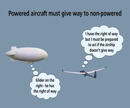
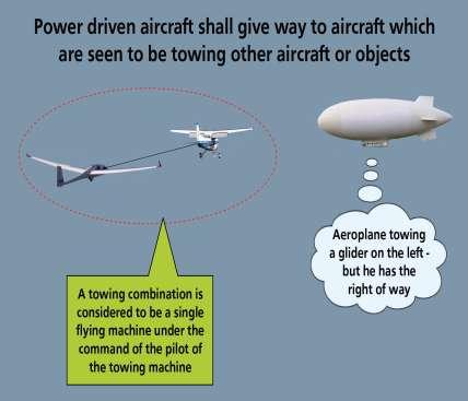
10 GENERAL RULES Converging. When two aircraft of the same type are converging at approximately the same level, the aircraft that has the other on its right shall give way. In order not to fly over, under or pass in front of the other aircraft, the aircraft that is obliged to give way should pass behind the other aircraft. In order to achieve this, the aircraft giving way should turn right. Where the two aircraft are not of the same type, the following order of priority will apply, and again, the method of giving way is to turn to the right: Power driven heavier than air aircraft (aeroplanes) shall give way to airships, gliders and balloons; Power driven lighter than air aircraft (airships) shall give way to gliders and balloons; Gliders shall give way to balloons; Power driven aircraft shall give way to aircraft which are seen to be towing other aircraft or objects.
11 Converging. GENERAL RULES

12 GENERAL RULES Overtaking. An aeroplane that is being overtaken has the right of way and the overtaking aircraft whether climbing or descending or in horizontal flight, shall keep out of the way of the other aircraft by altering its heading to the right and to maintain this position with regard to the other aircraft until well clear.
13 Landing. GENERAL RULES An aircraft in flight, or operating on the ground (or water), shall give way to aircraft landing or in the final stages of an approach to land. When two or more heavier than air aircraft are approaching an aerodrome to land, the aircraft at the higher level shall give way to the aircraft at the lower level, but the lower aircraft must not take advantage of this rule to cut in in front of another aircraft. In any event, power driven heavier than air aircraft shall give way to gliders.
14 GENERAL RULES Emergency Landing. An aircraft that is aware that another aircraft is in an emergency and is compelled to land, shall give way to that aircraft. Taking Off. An aircraft taxiing on the manoeuvring area shall give way to aircraft taking off or about to take off. Stop Bars. An aircraft taxiing on the manoeuvring area shall stop and hold at all lighted stop bars and may only proceed when the lights are switched off. Surface Movement of Aircraft. In the case of danger of collision between two aircraft taxiing on the movement area of an aerodrome, the following shall apply: Approaching head on. Both stop or where practicable alter course to the right to keep well clear. Converging. The one that has the other on its right shall give way. (Stop or turn to pass behind). Overtaking. The aircraft being overtaken has the right of way. The overtaking aircraft is to keep well clear of the other aircraft.

15 GENERAL RULES Aircraft Lights. The systems of displaying navigation lights, anti-collision lights and other lights designed to draw attention to the presence of an aircraft.
16 Aircraft Lights. GENERAL RULES Lights Displayed by Aircraft: Anti-collision lights - intended to attract attention to the aircraft - display the lights by day as well as by night. Navigation lights - intended to indicate the relative path of the aircraft to an observer. These lights are to be illuminated from sunset to sunrise or during any other period specified by the appropriate authority.!!! No other lights shall be displayed if they are likely to be mistaken for these lights.
17 GENERAL RULES Flight Plans. A flight plan is to be submitted prior to operating: A controlled flight; Any IFR flight within advisory airspace; Any flight within or into designated areas, or along designated routes, when so required by the appropriate ATS authority to facilitate the provision of flight information, the alerting and search and rescue services; Any flight within or into designated areas, or along designated routes, when so required by the appropriate ATS authority to facilitate co-ordination with appropriate military units (ADIZ) or with air traffic service units in adjacent states in order to avoid the possible need for interception for the purpose of identification Any flight across international borders;
18 GENERAL RULES A flight plan is to contain such of the following: Aircraft identification; Flight rules and type of flight; Number and type of aircraft and wake category; Equipment; Departure aerodrome; Estimated off blocks time (EOBT); Cruising speed(s) (TAS or Mach No.); Cruising level(s); Route to be followed; Destination aerodrome and estimated elapsed time (EET); Alternate aerodrome; Fuel endurance; Total number of persons on board (POB) including dead bodies; Emergency and survival equipment; Other information.
19 VFR/IFR rules. -Visual Meteorological Conditions (VFR); Applicable Rules. The operation of an aeroplane either in flight or on the movement area of an aerodrome is to be in accordance with the general rules and, when in flight, either: The visual flight rules (VFR), if the aircraft is flown in visual meteorological conditions (VMC) The instrument flight rules (IFR) IFR or VFR? A pilot may elect to fly in accordance with the Instrument Flight Rules in VMC (he/she may be required to do so by the ATS Authority in certain circumstances). A pilot must fly in accordance with the IFR in IMC. If a pilot elects to fly VFR he/she must do so only where VMC exist. Visual Meteorological Conditions. To fly under VFR, the visual meteorological conditions (VMC) must exist. This is defined by altitude (or Flight Level), flight visibility (the forward visibility from the flight deck of an aeroplane in flight), and distance (horizontally and vertically) from cloud, for the relevant classes of airspace. Classes of airspace are discussed fully in Chapter 14 - Airspace but basically, specify what rules are permitted and what type of control (if any) is applied by the Air Traffic Service. It is imperative that you know the VMC. VMC Criteria Classes A, B, C, D and E Airspace. At and above ft (FL100) the flight visibility requirement is 8 km with 300 m (1000 ft) vertically, and 1500 m horizontally from cloud. Below ft (FL100) the flight visibility requirement is reduced to 5 km. VMC Criteria Classes F and G Airspace. At and above ft (FL100) the flight visibility requirement is 8 km with 300 m (1000 ft) vertically, and 1500 m horizontally from cloud. Below ft (FL100) but above 3000 ft, the flight visibility requirement is reduced to 5 km. Below 3000 ft AMSL and within 1000 ft of the surface (where surface elevation is above 3000 ft) the flight visibility remains 5 km but VMC would exist if the aircraft was clear of cloud and within sight of the surface.
20 Visual Meteorological Conditions (VMC). With the exception of special VFR,VFR is only permitted in VMC. If a flight is operated under VFR and the meteorological conditions deteriorate such that it becomes impossible to continue in VMC the pilot must either: Land whilst able to maintain flight in VMC; or Change the route of the flight to maintain flight in VMC; or File an IFR flight plan and continue under IFR; or If within a CTR, request a SVFR clearance. Take-off/Landing Conditions. Unless authorized by ATC, VFR flights are not to take off or land at an aerodrome in a CTR, or enter the ATZ or traffic pattern: or When the cloud ceiling (see definition) is less than 450 m (1500 ft) When ground visibility (see definition) is less than 5 km Prohibition of VFR flight. Between sunset and sunrise, or during any other period as may be specified by the ATS authority, VFR flights are to be operated in accordance with the conditions required by such authority. VFR flights require an ATC clearance to operate: Above FL200. At transonic or supersonic speeds. VFR flight is not permitted above FL285 where RVSM is applied. Except when taking off and landing (or when specially approved by the authority e.g. air displays etc ), VFR flight is not allowed: Over the congested areas of cities, towns or settlements, or over an open air assembly of persons, at a height less than 300 m (1000 ft) above the highest obstacle within a radius of 600 m from the aircraft. At a height not less than 150 m (500 ft) above the surface (ground or water). VFR Flight Levels. In level cruising flight above the transition altitude (normally 3000 ft AGL), VFR flight is to be conducted at a VFR flight level appropriate to the magnetic track of the aircraft in accordance with the semi-
21 circular rule defined in paragraph When operating as a controlled VFR flight within controlled airspace (CAS), the FL or altitude will be specified by ATC in the ATC clearance for that flight. VFR flights are to comply with ATC instructions: When operating in class B, C or D airspace (in class A, VFR flight is not permitted) When forming part of aerodrome traffic at controlled aerodromes, or When operating as special VFR flights VFR Flight Plan. A VFR flight plan is to be filed before operating a VFR flight as a controlled flight. To indicate that the flight will be operated under VFR, the letter V is placed in item 8 of the flight plan form. If a flight is to commence under VFR and at some point en route change to IFR, the letter Z is placed in field 8 (V I = Z). Where the PIC of a VFR flight wishes to change to IFR: If a VFR flight plan was submitted, the PIC is to communicate the necessary changes to be effected to the current flight plan, or He/she is to submit an IFR flight plan and obtain a clearance prior to proceeding under IFR when in controlled airspace. EET. The time put in field 16 of a VFR flight plan is the time from take-off until overhead the destination aerodrome. Communications. Controlled VFR flights and VFR flights into airspace where the ATS authority considers it advisable are to maintain 2-way RTF communication with a controlling or monitoring ATSU and make position reports as necessary. In airspace classified as class E, F or G, VFR flights may operate without two-way communications (non-radio). Instrument Flight Rules IFR. For aircraft to be operated in IMC, (IMC exists when VMC does not!), the following rules are applicable. The rules are collectively known as the Instrument Flight rules (IFR). Annex 1 (Personnel Licensing ) states that where a licence is issued by a contracting state, it shall not permit the holder to act as PIC or co-pilot of an aeroplane under IFR unless the holder also holds a valid instrument rating (IR) appropriate to the aircraft category.
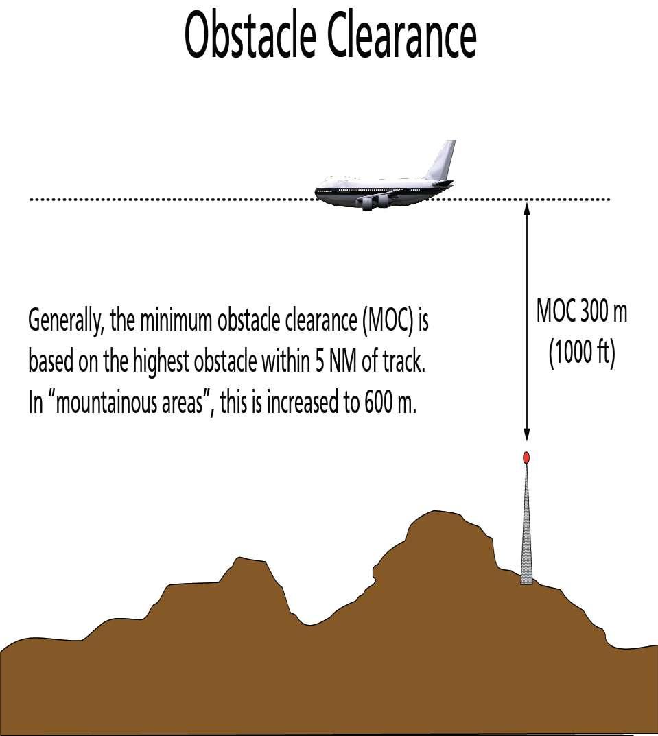
22 Aircraft Equipment. Aircraft are to be equipped with suitable instruments and with navigation equipment appropriate to the route to be flown. The necessary equipment is detailed in JAR OPS-1 and is covered in Operational Procedures lectures. Minimum Levels. Except when necessary for take-off and landing, or where specially authorized by the appropriate ATS authority, an IFR flight shall be flown at a level which is not below the minimum flight altitude established by the state whose territory is being overflown, or where no such minimum altitude is specified: Over high terrain or mountainous areas (not defined further), the minimum level must be at least 600 m (2000 ft) above the highest obstacle located within 8 km (5 NM) of the estimated position of the aircraft In areas other than in the above, minimum level is to be 300 m (1000 ft) above the highest obstacle within 8 km (5 NM) of the estimated position of the aircraft. IFR Flight Plans. An IFR flight plan is to include the letter I in item 8 of the flight plan form. If the intention is to change from IFR to VFR at some point during the flight the letter Y is to be inserted in item 8 (I V = Y). Changing from IFR to VFR. Where a pilot elects to change from IFR to VFR and the flight plan was not annotated Y in field 8, the pilot is to notify the ATS authority that flight under IFR is cancelled using the phrase cancelling my IFR flight and then the necessary changes to the current flight plan are to be passed. ATC will respond, IFR cancelled at. (time). When an IFR flight encounters VMC it shall not cancel IFR unless it is anticipated and intended that the flight will be continued for a reasonable period of time in uninterrupted VMC. In any event, a change of flight rules must only be at the request of the pilot. EET. The time put in field 16 of an IFR flight plan is the time from take-off until over the initial approach fix (IAF) for the instrument procedure at the destination aerodrome. IFR within Controlled Airspace (CAS). IFR flights within CAS are to comply with instructions issued by the appropriate ATC unit. IFR flights in cruising flight shall be flown at a cruising level, or when authorized to employ cruise climb techniques, between two levels or above a level, selected from:
23 The table of cruising levels (see below) A modified table of cruising levels, if applicable, for flight above FL410 (see below). IFR outside Controlled Airspace (CAS). The following rules apply to IFR flights outside CAS: Cruising Levels. IFR flights outside CAS are to be flown at cruising level appropriate to the magnetic track of the aircraft (see below). Communications. IFR flights operating outside CAS but within or into areas or along routes designated by the authority as those where the filing of a flight plan is required, are to establish communication and maintain a continuous listening watch with the ATS unit providing a flight information service (FIS). Position Reports. An IFR flight outside CAS and required to either submit a flight plan or maintain a listening watch with the unit providing an FIS, is to make position reports. For flights operating off ATS routes (airways) or in a defined operating area, position reports are to be made at intervals of 1 hour after an initial report has been made 30 minutes after leaving CAS or after commencing the controlled flight. Where a position report is meaningless (prolonged controlled flight operations in a confined area) an operations normal call is to be made at hourly intervals to prevent unnecessary activation of the alerting service. An example of an operations normal call is: London Control this is GADRF operations normal at 1020, 2000 ft and below. Will call again at 1120 CAE Oxford Aviation Academy (UK) Limited 2014
, restricted areas (indicated by the letter R) or prohibited areas (indicated by the letter P) and are detailed in the AIP.")
24 Restricted, Prohibited or Danger Areas Specification. Each state has the right to restrict or prohibit flight in territorial airspace for reasons of security or safety. Such areas are known as danger areas (indicated by the letter D), restricted areas (indicated by the letter R) or prohibited areas (indicated by the letter P) and are detailed in the AIP. These are designated by a code identifying the area and showing the altitude (usually in 1000s of ft) to which the area extends. Areas may be either permanently active (PERM) or activated by NOTAM. The area designator (for instance - D001) cannot be re-used for a period of not less than 12 months after the closure of the previously designated area. This allows for a full reprint of the 1/2 million topographical charts so that no confusion can exist. Visual Warning of Incursion. By day and night; a series of projectiles discharged from the ground at intervals of 10 secs, each showing on bursting red and green lights or stars, are used to warn aircraft that they are flying in or about to enter restricted, prohibited or danger areas.

25 Notices to Airmen (NOTAM) Definition: NOTAM are notices distributed by means of telecommunications containing information concerning the establishment, condition or change in any aeronautical facility, service, procedure or hazard, the timely knowledge of which is essential to personnel concerned with flight operations. Origination. NOTAM are to be originated and issued promptly whenever the information to be distributed is of a temporary nature and of short duration, or when operationally significant permanent changes, or temporary changes of long duration, are made at short notice (except when extensive text and/or graphics is essentially included, in which case, the information is published as an AIP supplement). NOTAM are required whenever information is of direct operational significance. AIRAC Notification. When an AIP amendment or an AIP Supplement is published in accordance with AIRAC procedures, NOTAM are to be originated giving a brief description of the contents, the effective date and the reference number to the amendment or supplement. This NOTAM shall come into force on the same effective date as the amendment or supplement.
26 Notice and Validity. NOTAM should remain in force as a reminder in the pre-flight information bulletin until the next checklist/summary is issued. Whenever possible, at least 24 hours advance notice is desirable, to permit timely completion of the notification process and to facilitate airspace utilization planning. NOTAM notifying the unserviceability of aids to air navigation, facilities or communication services should give an estimate of the period of unserviceability or the time at which restoration of service is expected. Excluded Matter. NOTAM should not include information of nonoperational importance including partial failures of lighting or ground systems, routine maintenance, any work in progress on runways not in use or if the equipment can be rapidly removed from the duty runway, temporary obstructions, local area parachuting, and the lack of apron marshalling services and road traffic control. Distribution. NOTAM are to be distributed to addressees to whom the information is of direct operational significance, and who would not otherwise have at least seven days prior notification. The aeronautical fixed telecommunication network (AFTN - teleprinter) is, whenever practicable, employed for NOTAM distribution. When NOTAM are sent by means other than the AFTN a six digit date-time group indicating the date and time of filing the NOTAM and the identification of the originator is used, preceding the text. NOTAM Checklists. A checklist of current NOTAM is issued at intervals of not more than one month. The checklist is to refer to the latest AIP amendment, AIP supplement and the internationally distributed AICs. Errors. When errors occur in a NOTAM, a NOTAM with a new number to replace the erroneous NOTAM will be issued or the erroneous NOTAM cancelled and a new NOTAM issued. Summary. A monthly printed plain language summary of NOTAM in force, including the indications of the latest AIP amendments, checklist of AIP supplements and AIC issued, is to be sent by the most expeditious means to recipients of the IAIP. CAE Oxford Aviation Academy (UK) Limited 2014
27 Instrument Procedures - Departures Agenda Instrument Procedures PANS OPS Instrument Departure Procedures
28 1. Instrument Procedures In order to permit all weather operation (low visibility take-off and landing) procedures must be established to provide track guidance and terrain avoidance for aircraft departing, and track guidance, terrain clearance and where special equipment is used, vertical displacement guidance for aircraft arriving at aerodromes. Low visibility operations (ICAO) are defined as take-off and landing operations with RVR less than 800 m. Remember, the minima for take-off from an aerodrome in a CTR is ground visibility not less than 5 km and cloud ceiling not less than 1500 ft. The criteria for the type of procedure to be employed are defined in terms of RVR and the limit to which a pilot is permitted to descend (DA/H or MDA/H). Clearly, obstacle avoidance during the procedure is of paramount importance. The fundamental assumption is that an instrument procedure (departure or arrival) will only be flown in conditions less than VMC. In this case, arrivals and departures from controlled aerodromes will be flown under IFR and hence subject to ATC. Therefore, prior to commencing any instrument procedure, an ATC clearance must be obtained. Procedures for departure and arrival are published and you are required to have the necessary plates (printed representations of the procedures) available on the flight deck. If you are required by ATC to divert to an aerodrome with which you are not familiar and do not have the plates, ATC will read the procedure, including the loss of communications and missed approach procedures, to you. Initially we will look at instrument departure procedures. The following ABBREVIATIONS are required knowledge
29
30 Obstacle Clearance It is implied that any procedure developed will not require the airplane to fly dangerously close to obstacles at any point during the procedure. Clearance from obstacles can be obtained by lateral clearance and vertical clearance. By requiring a pilot to fly the track accurately (within tolerances accepted) the aircraft can be guided over a surveyed flight path within the bounds of which, all obstacles can be determined and assessed. Obviously, the area surveyed must have finite limits. It is, however, not acceptable for, say, an area 5 NM wide to be surveyed and then permit aircraft to fly within guidance tolerance, 2.5 NM either side of the desired track. The extremities of the surveyed area must gradually permit higher obstacles until at the limit of reasonable expectations of accuracy (guidance tolerance - both equipment and flight technical), the guaranteed clearance is reduced to zero. This assessment is known as creation of MOC (minimum obstacle clearance areas). MOC is discussed later in this chapter. Obstacle clearance could be provided by assessing the highest obstacle to be flown over and by applying a safety margin to the obstacle height. An obstacle clearance altitude or height (OCA/H) can thus be obtained. This is the method of obtaining MSA and with refinements, minimum descent altitude/height (MDA/H) for non-precision procedures. As precision procedures provide height guidance, an obstacle 1000 ft high at 10 NM from the threshold is not as significant as an obstacle 150 ft high 1 NM from the threshold (assuming a 300 ft per mile glide slope). For precision systems, OCA/H is range from threshold dependent. It should therefore be obvious that OCA/H for precision procedures are less than OCA/H for non-precision. It must be stressed that, from an operational point of view, the obstacle clearance applied in the development of each instrument approach procedure is considered to be the minimum required for an acceptable level of safety in operations. If you have your own aeroplane and it is not used for commercial air transport, you may operate to the published OCA/H limits. Operators apply higher criteria resulting in aerodrome operating minima for commercial air transport.
31
32
33 PANS OPS Document The ICAO document that specifies the recommendations for instrument procedures is PANS OPS. The term PANS-OPS is commonly used to refer to the content of ICAO Doc The correct title of the document is Procedures for Air Navigation Services - Aircraft Operations. The document is printed in two volumes; Vol 1 - Flight Procedures; Vol 2 - Construction of Visual and Instrument Flight Procedures. Volume 1 describes operational procedures recommended for the guidance of flight operations personnel and we shall limit our considerations of instrument procedures to the content of Vol 1. Vol 1 outlines the various parameters on which the criteria of Vol 2 are based. Volume 2 is intended for the guidance of procedures specialists and describes the essential areas and obstacle clearance requirements for the achievement of safe, regular instrument flight operations. Both volumes present coverage of operational practices that are beyond the scope of Standards and Recommended Practices (SARPs) but with respect to which, a measure of international uniformity is desirable. PANs OPS, in expanding the SARPs of Annex 6, considers both departure and arrival procedures and to a lesser extent, en route procedures where obstacle clearance criteria should be taken into consideration.
34 Instrument Departure Procedures These procedures assume that all engines are operating. The design of an instrument departure procedure is, in general, dictated by the terrain surrounding the aerodrome, but may also be required to cater for ATC requirements (adjacent ATS routes, restricted, prohibited or danger areas and the proximity of other aerodromes). These factors in turn influence the type and position of navigation aids required to provide track guidance for the departure route. Airspace restrictions may also affect the position of navigation aids. From the pilot and operator point of view, the use of automatic take-off thrust control systems (ATTCS) and noise abatement procedures will need to be taken into account as well. Where no suitable navigation aid is available to provide specific track guidance, the criteria for omnidirectional (any direction) departures is applied. Wherever possible a straight departure will be specified, which is aligned with the runway. Where a departure route requires a turn of more than 15 to avoid an obstacle, a turning departure is constructed.
35 Requirements Where instrument departures are required, a departure procedure will be established for each runway to be used, and will define the procedure for the various categories of aircraft based on an all engines running PDG of 3.3%, or an increased PDG if required to achieve minimum obstacle clearance. The procedures assume that pilots will compensate for wind effects (known or estimated) when flying departure routes which are expressed as tracks to be made good. If radar vectoring is applied, pilots are required to fly the vector headings and not make allowance for the wind.
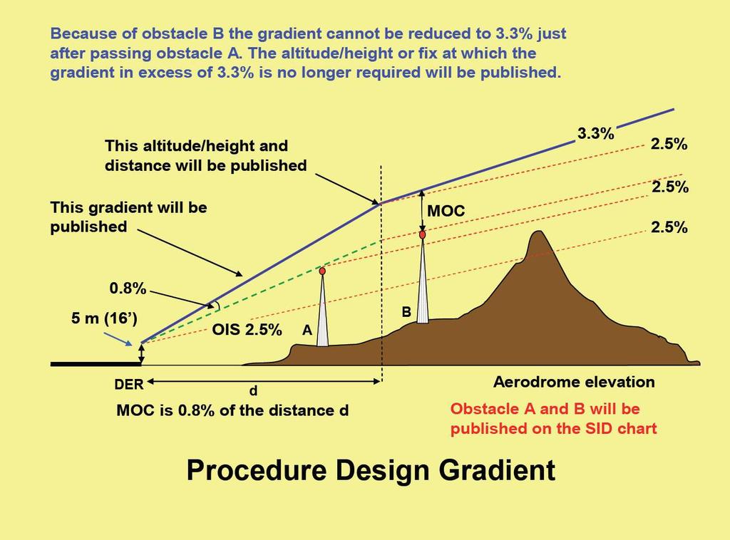
36 Obstacle Clearance As already stated, obstacle clearance is a primary safety consideration in instrument departure procedures. Unless otherwise stated a PDG of 3.3% is assumed. The PDG is made up of 2.5% gradient of obstacle identification surfaces or the gradient based on the most critical obstacle penetrating these surfaces (whichever is higher), and 0.8% increasing obstacle clearance. Gradients published will be specified to an altitude/ height after which the minimum gradient of 3.3% is considered to exist. The final PDG continues until obstacle clearance is ensured for the next phase of flight (en route, holding or approach). At this point the departure procedure ends and is marked by a significant point. The minimum obstacle clearance equals zero at the departure end of the runway (DER) and thereafter increases by 0.8% of the horizontal distance in the direction of flight, assuming maximum divergence of 15. In the turn initiation area for a turning departure a minimum obstacle clearance of 90 m (295 ft) is provided. Increased obstacle clearance will be provided in mountainous terrain. If DME is available, additional height/distance information is made available.
37
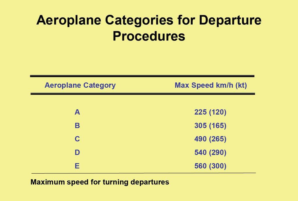
38 Mountainous Terrain What defines mountainous terrain is not specified. In deciding if the criteria for mountainous terrain are applicable, the designer takes notice of the prevailing wind conditions. If the average wind speed of 37 kph or more produces significant down draughts, increased obstacle clearance is applied. Aircraft Category It has already been mentioned that the major consideration in planning a departure route is to ensure adequate obstacle clearance. In determining the track over which the aircraft will fly speed is the determining factor. Aircraft are categorized by the maximum speed that the departure procedure can be flown. Wherever limiting speeds other than those specified in the table are published, they must be complied with to remain within the appropriate areas. If an aeroplane operation requires a higher speed, then an alternative departure procedure must be requested.
 from the end of the runway (DER) for straight departures, and within 10 km (5.4 NM) after completion of turns for turning departures.")
39 Standard Instrument Departures There are two basic types of departure route, straight, or turning. Departure routes are based on track guidance acquired within 20 km (10.8 NM) from the end of the runway (DER) for straight departures, and within 10 km (5.4 NM) after completion of turns for turning departures. When flying the route, the pilot is expected to correct for known wind and to remain within the protected airspace.

40 Straight Departure A straight departure is one in which the initial departure track is within 15 of the alignment of the runway. Track guidance may be provided by VOR, NDB or RNAV.
.")
41 Turning Departure If the departure track requires a turn of more than 15, a turning area is constructed and the turn required is commenced upon reaching a specified altitude/ height, or at a fix or at a facility (VOR, NDB etc...). Straight flight is assumed until reaching an altitude not less than 120 m (394 ft) above the elevation of the DER.
42

43 Emergencies It is the responsibility of the operator to establish procedures to cover the case of engine failure or an emergency in flight which occurs after V1.
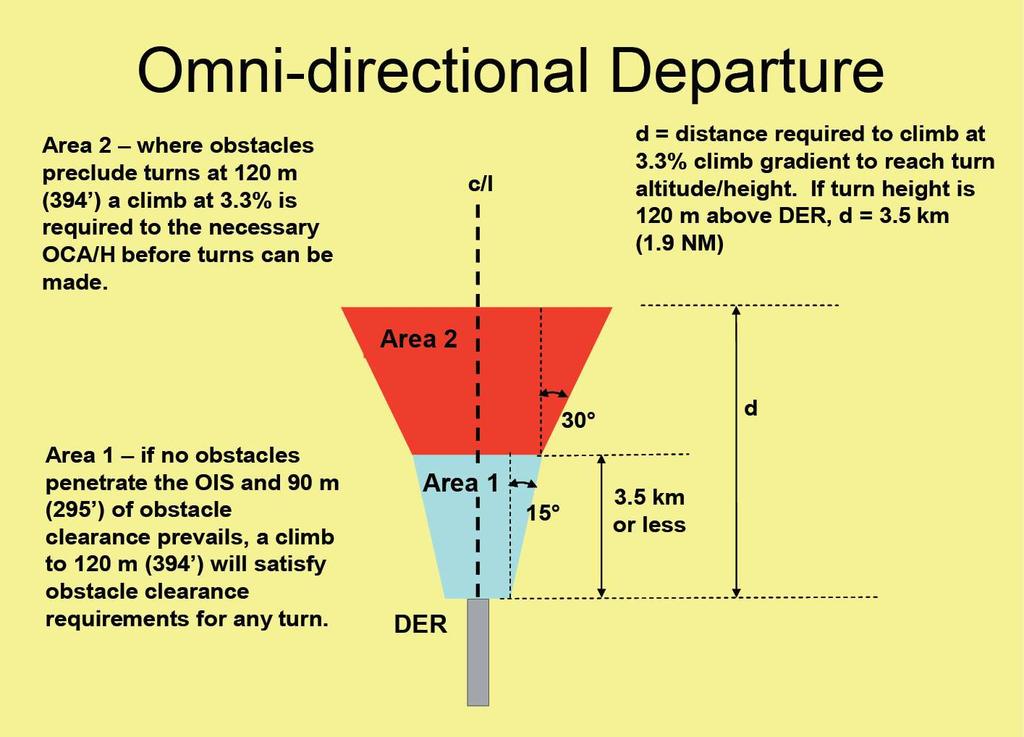
44 Omni-directional Departures Where no track guidance is provided in the design of a departure procedure, the omni-directional method is used which basically provides for initial departure tracks to be undefined. In other words, once off the end of the runway and at a safe height, the aircraft can be navigated in any direction required to achieve the initial en route point. It may be that some sectors of the departure area may contain obstacles which preclude departures in that direction, in which case the published procedures will be annotated to show the restricted sectors. The basic procedure is that the aircraft will climb on the extended runway centre line to 120 m (394 ft) above aerodrome elevation before turns can be specified, and at least 90 m (295 ft) of obstacle clearance will be provided before turns greater than 15 can be specified. Turns will not commence within 600 m of the beginning of the runway. Where obstacles do not permit the development of omni-directional procedures, it is necessary to fly a departure route (straight or turning), or ensure that ceiling and visibility will permit obstacles to be avoided by visual means.
45
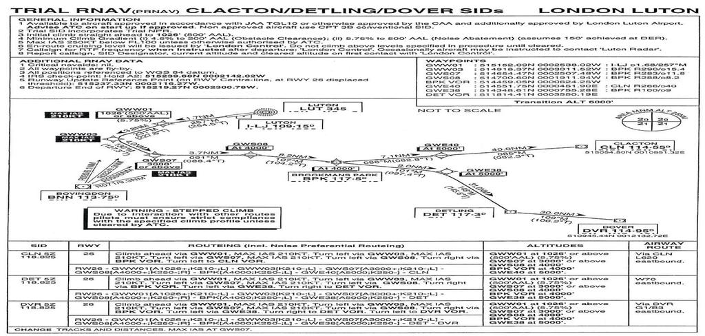
46 Published Information Departure routes and SID charts are published in accordance with standards contained in Annex 11 and Annex 4 to the Chicago Convention. Departure routes are labelled as RNAV (area navigation based on VOR/DME or GPS) only when that is the primary means of navigation utilized. For omni-directional departures, the restrictions will be expressed as sectors to be avoided or sectors in which minimum gradients and/or minimum altitudes are specified to enable an aeroplane to safely over fly obstacles. Minimum Sector Altitude (MSA) is also depicted on the plate and gives the lowest safe altitude for a defined sector (based on a navigational facility) to a range of 25 NM from the aerodrome (or facility). Figure 1 shows a typical SID plate. This plate details the departures from the runways at Heathrow and specifies that the point of joining the ATS route structure is the Compton VOR (CPT). All SIDs start at DER and end at the point of joining the ATS en route system. Note that each route has a specific designator e.g. CPT3G. In the ATC clearance for IFR flights, departure instructions will include a SID to the first airways point. The ATCO will refer to the SID by its designator. Note the means by which track guidance is applied. In a normal aeroplane fully airways fitted for IFR, the SID can always be complied with as there will be a minimum of two VOR/NAV boxes and one ADF. The Compton SID requires radio navigation using the LON and CPT VORs and the WOD NDB. DME is also specified

47 Fig. 1 A typical SID plate
48 The SID specifies DME distances to or from the facility with radials from VORs or QDMs for NDBs. The SID will also specify altitude restrictions in the form of Above..., or At..., as well as a diagram of the procedure. A narrative is always given in English. At the end of the SID the aircraft should be well placed to continue en route climbing in the airway or under radar control. At any time during the procedure, the pilot may be ordered to comply with radar vectoring requiring abandonment of the SID or abbreviation of the procedure. In such cases the pilot will be told that the aircraft is under radar control.
49 Area Navigation (RNAV) and RNP Based Departure Procedures The general principles relating to RNAV approach procedures also apply to RNAV departures based on a VOR/DME, DME/DME, basic GNSS and RNP criteria. Most FMS equipped aircraft are capable of following RNAV procedures but procedures may contain constraints on the system used. To use an RNP based procedure, the aircraft RNAV system must be approved for the published RNP and it must be confirmed before flight that the related VOR/DME stations are in fact working! Before flight, the pilot must also verify that the aircraft will be able to meet the RNP requirements for the segments to be flown as well as continue to monitor the system accuracy
50 Turns There are four kinds of turn that may be specified for an RNAV procedure: Turn at a fly-by waypoint; Turn at a fly-over waypoint; Turn at an altitude/height; and Fixed radius turn (generally for RNP based procedures) Use of FMS to Follow Conventional Departure Procedures. Where FMS is available, it may be used when flying the conventional departure procedures defined, provided the procedure is monitored using the basic display normally associated with that procedure, and the tolerances for flight using raw data on the basic display are complied with.
51
52 Holding Procedures
53 AGENDA: Holding Procedures Entry Sectors ATC Considerations Obstacle Clearance
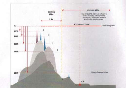
54 Holding Procedures - equivalent to temporary parking areas for aeroplanes; - remain (hold) in the vicinity of a radio navigation facility for as long as is required (fuel permitting
55 The Hold A hold is a racetrack shaped closed-course, where the start of the turn at one end is either a VOR, NDB, intersection of VOR radials or a DME distance (the holding fix ) The hold can have left-hand or right-hand turns Correct direction for a given hold is shown on the IFR chart (you can't choose the direction yourself) Standard is turns to the right, use right turns if no direction is specified Altitude for the holding pattern may also specified on the applicable chart The hold can be divided into four parts Turn at each end (180 degrees, and performed at standard rate = one minute) The leg on each side (outbound and inbound) generally one minute One turn in the hold therefore will take about four minutes


56 Timing generally begins here The Hold No direct tracking information on outbound leg estimate heading for winds Turn should be standard rate and never greater than 30 1min in still air at 14oooft and below; and 1 ½ min above 14000ft Bulgaria - 12th of May 2017
57 Information ATC will Provide A hold clearance is generally given 5 minutes ahead and contains the following components: clearance to the holding fix direction to hold from the holding fix; a specified radial, course, or inbound track that is used for the hold; the DME distance to be used for the outbound leg, if applicable; the altitude or flight level to be maintained; the time at which further clearance or approach clearance is to be expected (in the event of a communications failure) When a holding pattern is charted, ATC may omit all holding instructions except the charted holding direction and the statement as published. But will issue complete holding instructions when on pilot request PHRASEOLOGY- HOLD (direction) OF (fix/waypoint) ON (specified radial, course, bearing, track, airway, azimuth(s), or route.) If leg length is specified, (number of minutes/miles) MINUTE/MILE LEG If direction of turn is specified, LEFT/RIGHT TURNS.
58 Interpreting ATC Clearance The direction from the fix (Hold east of XYZ on the 090 radial) including the radial or bearing to hold. This holding direction is the side to hold on but is not the course for the inbound direction A radial is from a VOR, a bearing is TO an NDB Using a DME hold requires that you change your time for a leg into a distance for a leg Using DME you turn after the DME distance outbound regardless of time Expect further clearance (EFC) is required information for a hold. If ATC fails to give it, ask for it Don t accept a hold without it! Bulgaria - 12th of May 2017
59 . Lost Communications If the pilots are unable to obtain holding instructions prior to reaching the fix Hold in a standard pattern Hold on his arrival course to the fix Request instructions as soon as possible Bulgaria - 12th of May 2017
60 HOLDING PROCEDURES
61 Levels 1 Normal Conditions Turbulence Conditions up to 4250 m (14000 ft) inclusive 425 km/h (230 kt) km/h (170 kt) km/h (280 kt) km/h (170 kt) 4 above 4250 m (14000 ft) to 6100 m ( ft) inclusive above 6100 m (20000 ft) to m (34000 ft) inclusive 445 km/h (240 kt) km/h (280 kt) 490 km/h (265 kt) 5 or Mach 0.8, whichever is less 3 above m (34000ft) Mach 0.83 Mach 0.83
62 ENTRY SECTORS

63 SECTOR 1(Parallel Entry) Procedure Having reached the fix, the aircraft is turned left onto an outbound heading to make good a track reciprocal to the stated inbound holding track. This is maintained for the appropriate period of time relating to the altitude of the aircraft, and then the aircraft is turned left to return to the fix. On the second time over the fix, the aircraft is turned right to follow the holding pattern.

64 Sector 2 (Offset Entry) Procedure Having reached the fix, the aircraft is turned onto the heading to make good the track diverging 30 left of the reciprocal of the inbound holding track. This is maintained for the appropriate period of time relating to the altitude of the aircraft, and then the aircraft is turned right onto the holding track to return to the fix. On the second time over the fix, the aircraft is turned right to follow the holding pattern.

65 Sector 3 (Direct Entry) Procedure Having reached the fix, the aircraft is turned right to follow the holding pattern.
66 ATC Considerations Clearance to Join. As the holding pattern will be in controlled airspace and used for controlled flights, ATC (usually the approach controller) will pass an ATC clearance to the pilot with instructions to take up the holding pattern. The clearance will specify the location of the hold to be used, details of the holding pattern (unless routinely published), the holding level and any special requirements. "G-CD hold at OX FL50 expected approach time 1020" Hold OX FL G-CD" Followed by: Oxford Approach G-CD Is established in the hold at FL50"
67 Descending in the Hold. When the level below is vacant, the ATCO will reclear the pilot to the lower level. The pilot will acknowledge the clearance and immediately commence descent. Note: Shuttle is a climbing or descending manoeuvre in a holding pattern. "G-CD shuttle in the hold to FL40" "Leaving FL50 descending to FL40 G-CD " Followed by: "G-CD level FL40" Bulgaria - 12th of May 2017
68 Departing the Hold. At the appropriate time, the ATCO will instruct the pilot to commence the instrument procedure. It is usual to leave a holding pattern at the fix, but where radar is used the Approach Radar controller may vector the aircraft from any position in the holding pattern. Typically a clearance would be as follows: "G-CD advise when ready to commence the procedure" "Ready to commence the procedure G-CD" "G-CD set the Oxford QNH 1003, clear NDB/DME approach runway 01, report turning inbound at 2000 ft" 1003 set clear NDB/DME runway 01 wilco G-CD" Under certain circumstances (timed approaches) the ATCO will clear the aircraft to depart the holding pattern at a specific time to commence the procedure. In this case, the pilot should adjust the holding pattern leg lengths to depart the pattern from overhead the holding fix as close as possible to the stated clearance time.

69 Obstacle Clearance

70 Altimeter setting procedures; Objectives. The two main objectives of altimeter setting procedures are to: Provide adequate terrain clearance during all phases of flight especially departure and arrival. Provide adequate vertical separation between aircraft Altimeter Subscale Settings. There are three altimeter subscale settings that can be applied at any aerodrome. These are: QNH. This is the observed barometric pressure at an aerodrome adjusted in accordance with the ISA pressure lapse rate to indicate the pressure that would be observed if the observation was carried out at sea level. If QNH is set on the altimeter subscale, the altimeter would read aerodrome elevation at touchdown. QFE. This is the observed barometric pressure at an aerodrome which, if set on the altimeter subscale, would result in the altimeter reading zero at touchdown.
71 QNE. A situation can occur where the QNH is below the lowest altimeter subscale setting. For instance, if the altimeter subscale will not read below 940 hpa and the QNH is 935 hpa it would appear that the altimeter is useless. If, however, the altimeter subscale is set to a standard setting (e.g. 1013h Pa) then it would be possible to calculate what the altimeter would read at touchdown where the QNH is 930 hpa and the altimeter subscale is set to 1013 hpa using the ICAO ISA. Assume that the aerodrome elevation is 100 ft AMSL. On touchdown the altimeter will read: = 83 (amount of pressure wound on) ft (ISA interval) = 2241 ft ft = 2341 ft. In this case, 2341 ft is the QNE. A pilot would be instructed by the ATCO: G-CD set 1013 land with QNE 2340 There is a popular misconception amongst pilots that QNE is 1013 hpa. When used as a reference as opposed to a QNH, 1013 hpa is defined as the standard pressure setting (SPS). Therefore QNE is what the altimeter will read at touchdown with SPS set. Transition Definition. After take-off, the altimeter setting will be changed from QNH to SPS at some point. Likewise in the descent to land, the altimeter will be set to QNH from SPS at some point. The process that allows this to be done safely and at a logical point is called transition. This requires the altitude (or FL) at which this is done to be specified. The altitude above the aerodrome for change from QNH to SPS is called the transition altitude, and from SPS to QNH is the transition level. When flying below the transition altitude, the aircraft is flown at altitudes determined with reference to sea level pressure (QNH) and the vertical position is expressed in terms of altitude. Above the transition altitude, the vertical position is expressed in terms of flight levels. During a climb upon reaching the transition altitude, SPS is set and the climb continued to the desired flight level. In the descent, upon reaching the transition level, the QNH is then set and descent continued to the desired altitude. An exception to the above is when, on descent, the pilot is passed the QNH whilst still above the transition level in which case the pilot would refer to vertical position as an altitude.
72 Flight Levels. A flight level (FL) is defined as the vertical displacement of the aircraft above a constant level of barometric pressure related to 1013 hpa. Flight Level Zero (FL0) is located at the atmospheric pressure level of 1013 hpa. Subsequent flight levels are separated by a pressure interval corresponding to 500 ft in standard atmosphere. Flight levels are numbered as follows: FL30; FL35; FL40; FL45 etc. and FL100; FL105; FL110 etc. Transition Altitude. This is the altitude (with QNH set) above the aerodrome at which the altimeter subscale is reset to SPS and vertical position above that is then reported as a flight level. The transition altitude is specified for every aerodrome by the Authority of the State in which the aerodrome is located. The transition altitude shall be as low as possible but normally not less than 3000 ft. Transition altitudes are published in the AIP and shown on charts and instrument plates. A state may specify a general transition altitude (as in the USA, ft). Transition Level. The transition level is the flight level at which the altimeter is reset to the aerodrome QNH and subsequent flight is reported with reference to altitude. The transition level changes with the QNH. It is calculated by the Approach Controller at regular intervals and also when QNH changes. It is defined as the first available flight level above the transition altitude. This will be a
73 rounding up from what the altimeter is reading at the transition level with SPS set. Calculation of transition level is not required by the learning objectives. The flight crew shall be provided with the transition level : a. prior to reaching the level during the descent b. b. in the approach clearance c. c. when requested by the pilot Transition Layer. This is the airspace between the transition altitude with SPS set and the transition level. It is usually insignificant but some states require a minimum depth to the transition layer. When ascending through the transition layer (with SPS set) vertical position is reported as a flight level and when descending through the layer with QNH set, as an altitude.
74 CAE Oxford Aviation Academy (UK) Limited 2014
75 Aerodromes - Visual Aids, Markings and Signs
76 AGENDA: VISUAL AIDS FOR NAVIGATION RUNWAY MARKINGS TRANSVERSE STRIPE AIMING POINT MARKING TOUCHDOWN ZONE MARKINGS - TDZ TAXIWAY MARKINGS AIRCRAFT STAND MARKINGS SIGNS MARKERS
77 VISUAL AIDS FOR NAVIGATION Indicators and Signalling Devices a means of indicating the wind direction to pilots of non-radio aircraft; a means of communicating visual signals to nonradio aircraft is required to be positioned in the visual control room. Wind Direction Indicators at least one wind direction indicator (commonly called a 'wind sock') for each aerodrome.
78 Visual Aids for Navigation Landing Direction Indicator in a conspicuous place on the aerodrome in the form of a "T, white or orange, dependent on the colour that contrasts best with the background against which the indicator will be viewed. Signalling Lamp in the aerodrome control tower for the purpose of showing the light signals to aircraft either in the air or on the ground. Signal Panels and Signal Area Implies that non-radio traffic is accepted A signals area is not required if an aerodrome authority has proscribed routine non-radio traffic (the aerodrome would still be required to provide a service to an aircraft suffering a communications failure that has indicated the intention to land).
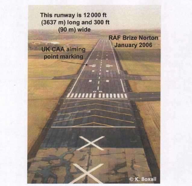
79 Runway Markings characters, numbers and shapes painted on the concrete surfaces of the aerodrome are found on runways, taxiways and aprons. may either give location or directional information or indicate a mandatory requirement e.g. to stop. The ICAO standard is for runway markings to be white and taxiway markings to be yellow. on runway surfaces of light colour, white markings can be improved by outlining them in black. may consist of numbers and letters, solid areas, or a series of longitudinal stripes providing an effect equivalent to the solid areas. Generally, runway markings assist the pilot with locating the threshold, identifying the runway, defining the centre line and locating the aiming point. Additionally for an instrument runway, as well as the aiming point, it will have touchdown zone markings.
80
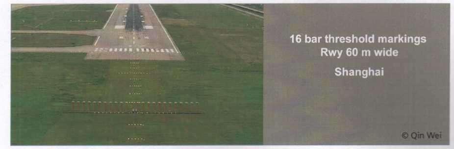
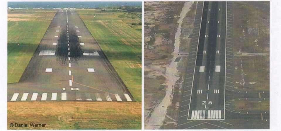
81 RUNWAY DESIGNATION MARKING two digit number and on parallel runways shall be supplemented with a letter For two parallel runways "09L" "09R"; For three parallel runways "09L" "09C" "09R"; For four parallel runways "09L" "09R" "10L" "10R" Runway Threshold Markings Runway Width Number of Stripes 18 m 4 23 m 6 30 m 8 45 m m or more 16
82

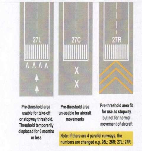
83 TRANSVERSE STRIPE - where a threshold is displaced from the extremity of a runway (the end of the concrete) or where the end is not at right angles to the runway centre line, a transverse stripe should be added. - when a runway threshold is permanently displaced, arrows shall be provided on the portion of the runway before the displaced threshold.
84 AIMING POINT MARKING. The aiming point marking indicates the position of the origin of the visual glide Aiming Point Marking Location Landing Distance Available (LDA) Less than 800 m Threshold to Beginning of Marking 150 m 800 m up to but not including 1200 m 250 m 300 m 1200 m up to but not including 2400 m 2400 m or more 400 m Figure 20.5 Location of aiming point marking
85 Touchdown Zone Markings - TDZ indicate the area of the runway where the aeroplane should be landed. give the pilot an indication of extent of the usable touchdown area and if distance coded, the length of the touchdown zone remaining. are required for code 2, 3 and 4 paved precision approach runways, and recommended for code 3 or 4 paved non-precision or noninstrument runways, where additional conspicuity is required. consist of pairs of rectangular markings symmetrically placed about the runway centre line with the number of pairs related to the landing distance available. For code 4 runways (2400 m or more in length) the TDZ markings have 6 pairs.
86
87 RUNWAY SIDE STRIPE MARKINGS -between the thresholds of precision runways, and paved runways where there is a lack of contrast between the runway edges and the shoulders or the surrounding terrain. -recommendation: side stripes are marked on all precision runways regardless of the contrast with the surrounding ground.

88 TAXIWAY MARKINGS REQUIREMENTS -The markings are yellow. -If there is a need to enhance conspicuity, the lines may be outlined in black.

89 Apron Safety Lines -Lines used in the apron areas the safe movement of aircraft into and out of parking stands -If all ground equipment and vehicles are parked or positioned behind the apron safety lines, a pilot or a marshaller can ignore the presence of those obstacles when parking aircraft. -are to be of a conspicuous colour which shall contrast with that used for aircraft stand markings.
90 Taxiway Centre Line Markings -provided on a paved taxiway, de/anti-icing facility and the apron areas where the code number is 3 or 4 (and recommended for code 1 and 2) -give guidance from the runway centre line, to the point on the apron where aircraft stand markings commence. -provided on a paved runway when the runway is part of a standard taxi-route and there is no runway centre line marking; or where the taxiway centre line is not coincident with the runway centre line. -a continuous yellow line. Bulgaria - 12th of May 2017
91 Runway Holding Position Marking -Holding points - at the entrance to all runways. -It could be more than one holding point at the entrance to a runway. - displayed at a runway holding point, at least the left hand side of the taxiway as the aeroplane approaches the runway(ideally the sign should be on both sides of the taxiway). -Destination: to extend all the way across the taxiway. -may also be established where the approach to a runway passes over a taxiway to another runway. In this case, the associated sign will specify what the holding point is for.
 runway, a non-precision")
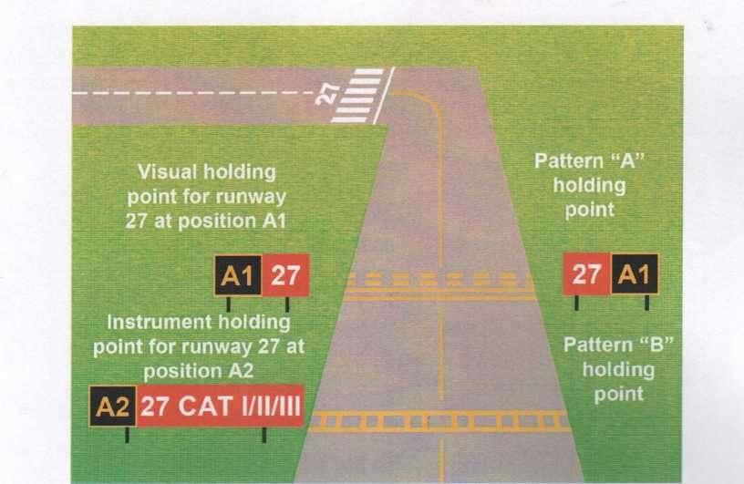
92 Patterns Pattern A. - The closest holding point to a runway will always be marked with a Pattern A marking -will be positioned at an intersection of a taxiway and a non-instrument (visual) runway, a non-precision approach runway or a take-off runway. - in case of a single taxi holding position is provided at an intersection of a taxiway and a precision approach category III or III runway -For a code 4 runway, the Pattern A holding point will be no closer than 75 m to the centre line of the runway. It is also the visual holding point.
 to the runway shall be as shown in")
93 Pattern B. -Where two or three taxi-holding positions are provided at such an intersection, the taxi-holding position marking closer (closest) to the runway shall be as shown in pattern A and the markings further from the runway shall be pattern B. -Any other holding point associated with a runway required on a taxiway will also be Pattern B.

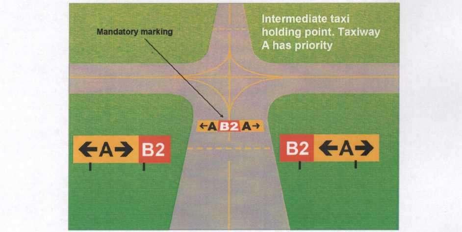
94 Intermediate Holding Position Marking. Where two (or more) taxiways cross, holding points are established at suitable distances from the crossing taxiway. -It may be that one taxiway has priority and the holding point marking may be augmented by a mandatory marking. -It should be coincident with a stop bar or clearance bar, where provided. -A taxiway intersection marking consists of a single broken yellow line.
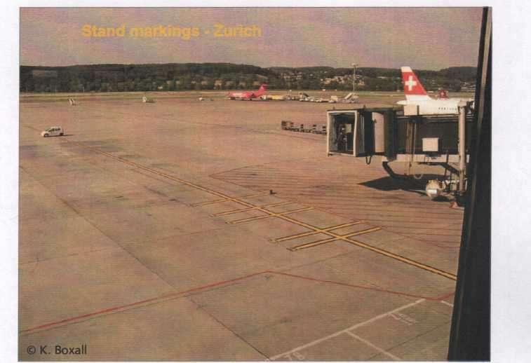
95 Aircraft Stand Markings -provided for designated parking positions on a paved apron and on de/anti-icing facilities. -include: stand identification, lead-in line, turn bar, turning line, alignment bar, stop line and lead-out line -The stand identification letter and/or number should be included a short distance after the beginning of the lead-in line. -Lead-in, turning and lead-out lines should normally be continuous in length. Where one or more sets of stand markings are superimposed on a stand, the lines should be continuous for the most demanding aircraft and broken for other aircraft. -The curved portions of lead-in, turning and lead-out lines -radii appropriate to the most demanding aircraft type for which the markings are intended.
96
97 ROAD HOLDING POSITION MARKINGS. -provided at all road entrances to a runway -located across the road at the holding position -be marked in accordance with the local road traffic regulations. MANDATORY INFORMATION MARKING -marked on the surface of the taxiway pavement -are holding point signs (runway designator in white on a red background) and no entry signs. - Pilots are not to pass any mandatory marking unless specifically cleared by ATC.
98 Information Markings. -displayed on the surface of the pavement, across the surface of the taxiway or apron where necessary and positioned so as to be legible from the cockpit of an approaching aircraft. -consist of an inscription in yellow, when it replaces or supplements a location sign; and an inscription in black, when it replaces or supplements a direction or destination sign. -In case of insufficient contrast between the marking and the pavement surface, the marking shall include a black background where the inscriptions are in yellow; and a yellow background where the inscriptions are in black. -combinations of characters and symbols. -numbers are only used for runways and runway designators.
99 SIGNS Destination: to convey a mandatory instruction, information on a specific location or destination on a movement area, or to provide other information as required. -frangible: -near a runway or taxiway - sufficiently low to preserve clearance for propellers and the engine pods of jet aircraft. -rectangular, with the longer side horizontal. -Signs showing numbers only refer to runways. -reflective and/or illuminated when intended for use at night. -In runway visual range conditions less than a value of 800 m, or At night in association with instrument runways, or At night in association with non-instrument runways where the code number is 3 or 4.
100 SIGNS Mandatory Instruction Signs -to identify the location beyond which an aircraft taxiing or vehicle -- include runway designation signs, category I, II and III holding position signs, taxiholding position signs, road-holding position signs and NO ENTRY signs. Locations of Signs - in positions such that pilots (or vehicle drivers) are able to see the sign. Positions : -A runway designation sign at a taxiway/runway intersection - located at least on the left side of a taxiway facing the direction of approach to the runway. -A NO ENTRY - at the beginning of the area to which the entrance is prohibited at least on the left hand side of the taxiway as viewed by the pilot. -A Category I, II or III holding position sign - on each side of the holding position marking facing the direction of the approach to the critical area. -A taxi-holding position - on the left-side of the taxi- holding position facing the approach to the runway or ILS/MLS critical/sensitive area, as appropriate, and where practicable, on each side of the taxi-holding position. Characteristics:- white letters/numbers on a red background

101 SIGNS
102 INFORMATION SIGNS Destination: to identify a specific location, or routing (direction or destination) -direction signs, location signs, destination signs, runway exit signs and runway vacated signs -on the left-hand side of the taxiway -runway exit signs - on the same side of the runway as the exit (i.e. left or right) -a runway vacated sign - at least on one side of the taxiway to indicate when the aircraft is clear of the sensitive area. -an information sign other than a location sign shall not be collocated with a mandatory instruction sign. Characteristics: Information Signs (except location signs): inscription in black on a yellow background. Location Signs: inscription in yellow on a black background (where it is a stand alone sign, has a yellow border)
103 INFORMATION SIGNS
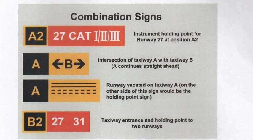
104 COMBINATION SIGNS
105 TAXIWAY DESIGNATORS
106 Aircraft Stand Identification Signs -located so as to be clearly visible from the cockpit of an aircraft prior to entering the stand -an inscription in black on a yellow background (in Europe may be white on a blue background) Road-Holding Position Signs -located 1.5 m from the edge of the road (left or right as appropriate to the local traffic regulations) at the holding position -an inscription in white on a red background -reflective or illuminated. Illumination of Signs -in RVR conditions less than 800 metres -at night in association with instrument runways -at night in association with non-instrument runways where the code number is 3 or 4
107 MARKERS -object which is displayed above ground level in order to indicate an obstacle or delineate a boundary -used where lights are not provided -used to indicate: -the extremity of a taxiway where snow has fallen, or to mark areas of bad ground on a grass aerodrome. -the extent of an unpaved runway is not clearly indicated by the appearance of its surface compared with that of the surrounding ground. Where there are no lights, markers of flat rectangular or conical shape should be placed so as to delimit the runway clearly. The flat rectangular markers - minimum size of 1 m by 3 m and should be placed with their long dimension parallel to the runway centre line. The conical markers - a height not exceeding 50 cm.

108 BOUNDARY MARKERS -provided at an aerodrome where the landing area has no runway -spaced along the boundary of the landing area at intervals of not more than 200 m, if the type shown below is used, or approximately 90 m, if the conical type is used with a marker at any corner. -coloured to contrast with the background against which they will be seen.
AIR LAW AND ATC PROCEDURES
 1 The International Civil Aviation Organisation (ICAO) establishes: A standards and recommended international practices for contracting member states. B aeronautical standards adopted by all states. C
IFR SEPARATION WITHOUT RADAR
 1. Introduction IFR SEPARATION WITHOUT RADAR When flying IFR inside controlled airspace, air traffic controllers either providing a service to an aircraft under their control or to another controller s
CHAPTER 5 SEPARATION METHODS AND MINIMA
 CHAPTER 5 SEPARATION METHODS AND MINIMA 5.1 Provision for the separation of controlled traffic 5.1.1 Vertical or horizontal separation shall be provided: a) between IFR flights in Class D and E airspaces
Chapter 6. Airports Authority of India Manual of Air Traffic Services Part 1
 Chapter 6 6.1 ESSENTIAL LOCAL TRAFFIC 6.1.1 Information on essential local traffic known to the controller shall be transmitted without delay to departing and arriving aircraft concerned. Note 1. Essential
USE OF RADAR IN THE APPROACH CONTROL SERVICE
 USE OF RADAR IN THE APPROACH CONTROL SERVICE 1. Introduction The indications presented on the ATS surveillance system named radar may be used to perform the aerodrome, approach and en-route control service:
SULAYMANIYAH INTERNATIONAL AIRPORT MATS CHAPTER 11
 KURDISTAN REGIONAL GOVERNMENT SULAYMANIYAH INTERNATIONAL AIRPORT MATS CHAPTER 11 SEPARATION STANDARDS & APPLICATIONS International and Local Procedures ( First Edition ) April 2012 Ff Prepared By Fakhir.F.
Contents. Subpart A General 91.1 Purpose... 7
 Contents Rule objective... 3 Extent of consultation... 3 Summary of comments... 4 Examination of comments... 6 Insertion of Amendments... 6 Effective date of rule... 6 Availability of rules... 6 Part 91
1.2 An Approach Control Unit Shall Provide the following services: c) Alerting Service and assistance to organizations involved in SAR Actions;
 Alerting Service and assistance to organizations involved in SAR Actions;") Section 4 Chapter 1 Approach Control Services Approach Control Note: This section should be read in conjunction with Section 2 (General ATS), Section 6 (Separation Methods and Minima) and Section 7 (ATS
Section 4 Chapter 1 Approach Control Services Approach Control Note: This section should be read in conjunction with Section 2 (General ATS), Section 6 (Separation Methods and Minima) and Section 7 (ATS
SECTION 4 - APPROACH CONTROL PROCEDURES
 SECTION 4 - APPROACH CONTROL PROCEDURES CHAPTER 1 - PROVISION OF SERVICES 1.1 An approach control unit shall provide:- a) Approach control service. b) Flight Information service. c) Alerting service. RESPONSIBILITIES
Lecture Minimum safe flight altitude
 Lecture Minimum safe flight altitude Calculate of minimum safe flight altitude, safe flight altitude in approach zone, in circle zone (circle altitude), minimum safe flight altitude in aerodrome area,
Chapter 6. Nonradar. Section 1. General DISTANCE
 12/10/15 JO 7110.65W Chapter 6. Nonradar Section 1. General 6 1 1. DISTANCE Use mileage based (DME and/or ATD) procedures and minima only when direct pilot/controller communications are maintained. FIG
ENR 1.7 ALTIMETER SETTING PROCEDURES
 AIP LEBANON ENR 1.7-1 11 APR 2008 ENR 1.7 ALTIMETER SETTING PROCEDURES 1. Introduction: 1.1 The procedures herein describe the method used in providing adequate vertical separation between aircraft and
Consideration will be given to other methods of compliance which may be presented to the Authority.
 Advisory Circular AC 139-10 Revision 1 Control of Obstacles 27 April 2007 General Civil Aviation Authority advisory circulars (AC) contain information about standards, practices and procedures that the
IFR SEPARATION USING RADAR
 IFR SEPARATION USING RADAR 1. Introduction When flying IFR inside controlled airspace, air traffic controllers either providing a service to an aircraft under their control or to another controller s traffic,
OPERATIONS MANUAL PART A
 PAGE: 1 Table of Content A.GENERAL /CHAPTER 7 -....3 7.... 3 7.1 Minimum Flight Altitudes /Flight Levels VFR Flight... 3 7.2 Minimum Flight Altitudes /Flight Levels IFR Flight... 4 7.2.1 IFR flights non
SAFETYSENSE LEAFLET AIR TRAFFIC SERVICES OUTSIDE CONTROLLED AIRSPACE
 SAFETYSENSE LEAFLET 8e AIR TRAFFIC SERVICES OUTSIDE CONTROLLED AIRSPACE 1 INTRODUCTION 2 NON-RADAR SERVICES 3 RADAR SERVICES 4 HOW TO OBTAIN A SERVICE 5 RADAR SERVICE LIMITATIONS 1 INTRODUCTION a) In this
GOVERNMENT OF INDIA OFFICE OF DIRECTOR GENERAL OF CIVIL AVIATION
 GOVERNMENT OF INDIA OFFICE OF DIRECTOR GENERAL OF CIVIL AVIATION ANSS AC NO. 1 of 2017 31.07. 2017 Air Space and Air Navigation Services Standard ADVISORY CIRCULAR Subject: Procedures to follow in case
Flight Crew Licensing
 Flight Crew Licensing Chapter 5 INTRODUCTION 5.1 Requirement. The Learning Objectives and the Syllabus for 010 Air Law require the student to have knowledge of the SARPS detailed in Annex 1 (Personnel
SECTION 6 - SEPARATION STANDARDS
 SECTION 6 - SEPARATION STANDARDS CHAPTER 1 - PROVISION OF STANDARD SEPARATION 1.1 Standard vertical or horizontal separation shall be provided between: a) All flights in Class A airspace. b) IFR flights
AERONAUTICAL SERVICES ADVISORY MEMORANDUM (ASAM) Focal Point: Gen
 Focal Point: Gen") Page 1 of 6 1 INTRODUCTION Each route shall be assigned a designator that is unique for that aerodrome. The designator shall be defined in accordance with Annex 11, Appendix 3. In addition, the first 4
Page 1 of 6 1 INTRODUCTION Each route shall be assigned a designator that is unique for that aerodrome. The designator shall be defined in accordance with Annex 11, Appendix 3. In addition, the first 4
 IFR 91.157 Must be instrument rated to fly special VFR at Night (civil twilight to civil twilight, sun 6 degrees below horizon) 91.159 Unless in a holding pattern of 2 minutes or less, VFR cruising altitude
CLEARANCE INSTRUCTION READ BACK
 CLEARANCE INSTRUCTION READ BACK 1. Introduction An ATC clearance or an instruction constitutes authority for an aircraft to proceed only in so far as known air traffic is concerned and is based solely
BFR WRITTEN TEST B - For IFR Pilots
 (61 Questions) (Review and study of the FARs noted in parentheses right after the question number is encouraged. This is an open book test!) 1. (91.3) Who is responsible for determining that the altimeter
MINIMUM FLIGHT ALTITUDES
 MINIMUM FLIGHT ALTITUDES 1. Introduction Minimum flight altitudes are created first to ensure safety, awareness and adequate radio navigation reception for aircraft flying at the same time in specific
Chapter 6. Brize Radar, Speedbird 213 Heavy, request radar advisory. Speedbird 123 change call sign to BA 123
 INTRODUCTION The procedures for and VFR are mostly identical but some words and procedures are generally only used by large commercial aircraft; hence they appear in this section. In this chapter we will
CHAPTER 4 AIR TRAFFIC SERVICES
 CHAPTER 4 AIR TRAFFIC SERVICES 4.1 Objectives of the air traffic services 4.1.1 The objectives of the air traffic services shall be to: a) prevent collisions between aircraft; b) prevent collisions between
Manual of Radiotelephony
 Doc 9432 AN/925 Manual of Radiotelephony Approved by the Secretary General and published under his authority Fourth Edition - 2007 International Civil Aviation Organization AMENDMENTS The issue of amendments
INTERNATIONAL FEDERATION OF AIR TRAFFIC CONTROLLERS ASSOCIATIONS. Agenda Item: B.5.12 IFATCA 09 WP No. 94
 INTERNATIONAL FEDERATION OF AIR TRAFFIC CONTROLLERS ASSOCIATIONS 48 th ANNUAL CONFERENCE - Dubrovnik, 20 th to 24 th April 2009 Agenda Item: B.5.12 IFATCA 09 WP No. 94 Study Go Around Procedures When on
AERODROME OPERATING MINIMA
 Title: Determination of Aerodrome Operating Minima Page 1 of 8 AERODROME OPERATING MINIMA 1. PURPOSE 1.1 The purpose of this Advisory Circular is to provide methods to be adopted by operators in determining
Operational Procedures
 CHAPTER four OPERATIONAL PROCEDURES Contents ESTABLISHMENT OF PROCEDURES............................ 29 PERFORMANCE AND OPERATING LIMITATIONS................... 29 MASS LIMITATIONS......................................
LATVIJAS CIVILĀS AVIĀCIJAS AĂENTŪRA EKSAMINĒŠANA AIR LAW PPL(A) Variants: 107 WEB. Jautājumu skaits - 20 Eksāmena ilgums 60 minūtes
 Variants: 107 WEB. Jautājumu skaits - 20 Eksāmena ilgums 60 minūtes") LATVIJAS CIVILĀS AVIĀCIJAS AĂENTŪRA EKSAMINĒŠANA AIR LAW PPL(A) Variants: 107 WEB Jautājumu skaits - 20 Eksāmena ilgums 60 minūtes 1 Interception Procedure by DAY or NIGHT: If the pilot of an intercepted
LATVIJAS CIVILĀS AVIĀCIJAS AĂENTŪRA EKSAMINĒŠANA AIR LAW PPL(A) Variants: 107 WEB Jautājumu skaits - 20 Eksāmena ilgums 60 minūtes 1 Interception Procedure by DAY or NIGHT: If the pilot of an intercepted
Air Traffic Services Standards and Procedures Contents
 Air Traffic Services Standards and Procedures Contents Effective Date Preface 18 May 2007 Contents 31 July 2013 Section 1 Glossary 22 July 2009 Chapter 1 Definitions 8 February 2013 Chapter 2 Abbreviations
Air Law. Iain Darby NAPC/PH-NSIL IAEA. International Atomic Energy Agency
 Air Law Iain Darby NAPC/PH-NSIL International Atomic Energy Agency Aviation Regulations International Civil Aviation Organisation (ICAO) Convention on International Civil Aviation also known as the Chicago
Air Traffic Services Standards and Procedures Contents
 Air Traffic Services Standards and Procedures Contents Effective Date Preface 18 May 2007 Contents 22 July 2009 Section 1 Glossary 22 July 2009 Chapter 1 Chapter 3 Chapter 4 Definitions Abbreviations Conversion
Air Law and ATC Procedures Subject: AIR LAW AND ATC PROCEDURES
 Air Law and ATC Procedures Subject: Classroom Instruction: YES (Workshop) Appr. # of Instruction Hrs: 3 Internal Examination: YES ITSS (online) / Offline International Law: Conventions, Agreements and
TANZANIA CIVIL AVIATION AUTHORITY AIR NAVIGATION SERVICES INSPECTORATE. Title: CONSTRUCTION OF VISUAL AND INSTRUMENT FLIGHT PROCEDURES
 Page 1 of 8 1. PURPOSE 1.1. This Advisory Circular provides guidance to personnel involved in construction of instrument and visual flight procedures for publication in the Aeronautical Information Publication.
JAA Administrative & Guidance Material Section Five: Licensing, Part Two: Procedures
 INTRODUCTION Preliminary general remark: 1 To fully appreciate and understand subject 033, the applicant will benefit from background knowledge in subjects 010, 020, 031, 032/034, 050, 060, 070 and 080.
FLIGHT OPERATIONS PANEL (FLTOPSP)
") International Civil Aviation Organization FLTOPSP/1-WP/3 7/10/14 WORKING PAPER FLIGHT OPERATIONS PANEL (FLTOPSP) FIRST MEETING Montréal, 27 to 31 October 2014 Agenda Item 4: Active work programme items
International Civil Aviation Organization FLTOPSP/1-WP/3 7/10/14 WORKING PAPER FLIGHT OPERATIONS PANEL (FLTOPSP) FIRST MEETING Montréal, 27 to 31 October 2014 Agenda Item 4: Active work programme items
Gestão de Tráfego Aéreo 2015/2016 Exam Name Student ID Number. I (5.5/20, 0.5 each)
") Gestão de Tráfego Aéreo 2015/2016 Exam 2016.01.04 Name Student ID Number I (5.5/20, 0.5 each) What is each contracting state of ICAO required to provide? [ ] Modern radio navigation facilities for aeroplanes
Gestão de Tráfego Aéreo 2015/2016 Exam 2016.01.04 Name Student ID Number I (5.5/20, 0.5 each) What is each contracting state of ICAO required to provide? [ ] Modern radio navigation facilities for aeroplanes
distance and time to descend from a given level or altitude. LO Find the frequency and/or identifiers of radio-navigation aids from charts.
 Anne II to ED Decision 2016/008/R (1) For mass definitions, please refer to Chapter D. Syllabus 033 00 00 00 FLIGHT PLANNING AND MONITORING Aeroplane Helicopter / 033 01 00 00 FLIGHT PLANNING FOR VFR FLIGHTS
SERA AND CAP694 (THE UK FLIGHT PLANNING GUIDE) - GUIDANCE. Correct to 1 May This document is for guidance only and is subject to change.
 - GUIDANCE. Correct to 1 May This document is for guidance only and is subject to change.") SERA AND CAP694 (THE UK FLIGHT PLANNING GUIDE) - GUIDANCE Correct to 1 May 2015. This document is for guidance only and is subject to change. Implementing Regulation (EU) 923/2012, supporting Acceptable
SERA AND CAP694 (THE UK FLIGHT PLANNING GUIDE) - GUIDANCE Correct to 1 May 2015. This document is for guidance only and is subject to change. Implementing Regulation (EU) 923/2012, supporting Acceptable
The aim of any instrument approach is to allow the aircraft to safely descend to a low altitude in order to become visual.
 INSTRUMENT APPROACH CHARTS "An instrument approach is just a series of straight lines joined by rate one turns" Ron Magrath The aim of any instrument approach is to allow the aircraft to safely descend
Any queries about the content of the attached document should be addressed to: ICAO EUR/NAT Office:
 Serial Number: 2018_005 Subject: Special Procedures For In-Flight Contingencies in Oceanic Airspace Originator: NAT SPG Issued: 17 DEC 2018 Effective:28 MAR 2019 The purpose of this North Atlantic Operations
CONTROLLED AIRSPACE CONTAINMENT POLICY
 Safety and Airspace Regulation Group (SARG) 17 January 2014 Policy Statement 1 Overview CONTROLLED AIRSPACE CONTAINMENT POLICY 1.1 UK airspace design policy for ATS Routes, SIDs and STARs is based upon
Appendix D Rules of the Air
 General Operating Instructions Part 91 Page 1 Appendix D Rules of the Air (a) (b) This Appendix contains the Rules of the Air, as specified in the AN(OT)O. The Rules of the Air are reproduced in this Appendix
THE CIVIL AVIATION ACT (No. 21 of 2013 THE CIVIL AVIATION (OPERATION OF AIRCRAFT) (AMENDMENT) REGULATIONS, 2015
 (AMENDMENT) REGULATIONS, 2015") LEGAL NOTICE. THE CIVIL AVIATION ACT (No. 21 of 2013 THE CIVIL AVIATION (OPERATION OF AIRCRAFT) (AMENDMENT) REGULATIONS, 2015 Citation GN. No. of 20 Citation 1. These Regulations may be cited as the Civil
LEGAL NOTICE. THE CIVIL AVIATION ACT (No. 21 of 2013 THE CIVIL AVIATION (OPERATION OF AIRCRAFT) (AMENDMENT) REGULATIONS, 2015 Citation GN. No. of 20 Citation 1. These Regulations may be cited as the Civil
Regulations & Obligations
 Regulations & Obligations Thursday, March 24, 2015 9:00 a.m. 10:00 a.m.) PRESENTED BY: John Harpool Richard White Adam Hartley International Operators Conference San Diego, CA March 21 24, 2016 Sources:
SUBPART C Operator certification and supervision
 An AOC specifies the: SUBPART C Operator certification and supervision Appendix 1 to OPS 1.175 Contents and conditions of the Air Operator Certificate (a) Name and location (principal place of business)
Understanding the Jeppesen. Updates: Changes, Errata and What s New
 Understanding the Jeppesen Updates: Changes, Errata and What s New www.understandingaviation.com info@understandingaviation.com Table of Contents Changes... 1 Errata... 5 What s New... 5 Changes Law Amendment
SPECIAL PROCEDURES FOR IN-FLIGHT CONTINGENCIES IN OCEANIC AIRSPACE OF SEYCHELLES FIR
 Phone: 248-4384186 AFS: FSIAYNYX FAX: 248-4384179 Email: sezais@scaa.sc REPUBLIC OF SEYCHELLES CIVIL AVIATION AUTHORITY AERONAUTICAL INFORMATION SERVICE P.O.BOX 181, VICTORIA SEYCHELLES AIP SUPPLEMENT
AIP PORTUGAL ENR NOV-2007
 AIP PORTUGAL ENR 1.6-1 ENR 1.6 RADAR SERVICES AND PROCEDURES PROVISION OF RADAR SERVICES WITHIN LISBOA AND SANTA MARIA FIR / UIR Introduction Air Traffic Control Services within Lisboa and Santa Maria
EASA NPA on SERA Part ENAV Response sheet. GENERAL COMMENTS ON NPA PACKAGE Note: Specific comments are provided after the General Comments
 EASA NPA on SERA Part ENAV Response sheet GENERAL COMMENTS ON NPA PACKAGE te: Specific comments are provided after the General Comments 1 SERA Parts C and D ENAV still misses clarity on the whole scope
AERONAUTICAL SERVICES ADVISORY MEMORANDUM (ASAM) Focal Point: Gen
 Focal Point: Gen") Page 1 of 14 1 INTRODUCTION This guidance material has been prepared for use for the definition of protected surfaces in the vicinity of aerodromes. Survey information for an aerodrome is essential for
Page 1 of 14 1 INTRODUCTION This guidance material has been prepared for use for the definition of protected surfaces in the vicinity of aerodromes. Survey information for an aerodrome is essential for
Safety and Airspace Regulation Group
 Safety and Airspace Regulation Group 24 August 2015 Policy Statement POLICY FOR POINT MERGE AND TROMBONE TRANSITION PROCEDURES 1 Introduction 1.1 The Point Merge transition procedure is an Area Navigation
Learning Objectives 7.3 Flight Performance and Planning Flight Planning & Flight Monitoring
 030 00 00 00 FLIGHT PERFORMANCE AND PLANNING 033 00 00 00 FLIGHT PLANNING AND FLIGHT MONITORING 033 01 00 00 FLIGHT PLANNING FOR VFR FLIGHTS Remark Using Training Route Manual VFR charts or CQB Annexes
MetroAir Virtual Airlines
 MetroAir Virtual Airlines NAVIGATION BASICS V 1.0 NOT FOR REAL WORLD AVIATION GETTING STARTED 2 P a g e Having a good understanding of navigation is critical when you fly online the VATSIM network. ATC
Separation Methods and Minima
 Section 6 Chapter 1 Separation Methods and Minima General 1 Introduction 1.1 This chapter contains procedures and procedural separation minima for use in the separation of aircraft in the en route phase
VFR PHRASEOLOGY. The word IMMEDIATELY should only be used when immediate action is required for safety reasons.
 VFR PHRASEOLOGY 1. Introduction 1.1. What is phraseology? The phraseology is the way to communicate between the pilot and air traffic controller. This way is stereotyped and you shall not invent new words.
Advisory Circular AC61-3 Revision 12 SUPERSEDED Describe the duties of the pilot-in-command, as laid down in CA Act 1990 S13 and 13A.
 Subject No 4 Air Law Each subject has been given a subject number and each topic within that subject a topic number. These reference numbers will be used on knowledge deficiency reports and will provide
Overview ICAO Standards and Recommended Practices for Aerodrome Safeguarding
 Overview ICAO Standards and Recommended Practices for Aerodrome Safeguarding References The Convention on International Civil Aviation (Chicago Convention) ICAO SARPS Annex 14 Vol. I, 7 th Edition, July
Appendix A COMMUNICATION BEST PRACTICES
 Appendix A COMMUNICATION BEST PRACTICES 1. GENERAL 1.1 It is apparent from investigation reports and surveys regarding runway safety occurrences that communication issues are frequently a causal or contributory
IVAO Flight Operations Department Indonesia (ID) Division Procedures
 Division Procedures") IVAO Flight Operations Department Indonesia (ID) Division Procedures Revised April 12 rd, 2010 Please consult also the local application of common procedures on http://www.ivao.web.id 1. General 1.1 In
IVAO Flight Operations Department Indonesia (ID) Division Procedures Revised April 12 rd, 2010 Please consult also the local application of common procedures on http://www.ivao.web.id 1. General 1.1 In
ALTIMETER SETTING PROCEDURES
 AIP New Zealand ENR 1.7-1 ENR 1.7 ALTIMETER SETTING PROCEDURES 1 INTRODUCTION 1.1 General 1.1.1 The requirements for altimeter setting are detailed in CAR Part 91. The requirements are summarised in this
CHAPTER 7 AEROPLANE COMMUNICATION AND NAVIGATION EQUIPMENT
 CHAP 7-1 CHAPTER 7 COMMUNICATION AND NAVIGATION EQUIPMENT 7.1 COMMUNICATION EQUIPMENT 7.1.1 An aeroplane shall be provided with radio communication equipment capable of: a) conducting two-way communication
Guidelines for NOTAM Workflow and Allocation of Responsibilities
 Guidelines for NOTAM Workflow and Allocation of Responsibilities May 19 2011 INDEX 1- MAIN OBJECTIVES 1 2- ORIGINATION OF NOTAM 1 3- VALUE OF A NOTAM 3 4- DURATION OF NOTAM 4 5- THE AERONAUTICAL DATA CHAIN
ENR 1.1 GEN. RULES (Insert para 13 in ENR 1.1 of AIP India as follows)
") TEL: +91-11-24632950 Extn: 2219/2233 AFS: VIDDYXAX FAX: +91-11-24615508 Email: gmais@aai.aero INDIA AERONAUTICAL INFORMATION SERVICE AIRPORTS AUTHORITY OF INDIA RAJIV GANDHI BHAVAN SAFDARJUNG AIRPORT NEW
TEL: +91-11-24632950 Extn: 2219/2233 AFS: VIDDYXAX FAX: +91-11-24615508 Email: gmais@aai.aero INDIA AERONAUTICAL INFORMATION SERVICE AIRPORTS AUTHORITY OF INDIA RAJIV GANDHI BHAVAN SAFDARJUNG AIRPORT NEW
Single Engine Instrument Training Record I PREFLIGHT PREPARATION WEATHER INFORMATION weather reports and forecasts. pilot and radar reports.
 Single Engine Instrument Training Record I PREFLIGHT PREPARATION WEATHER INFORMATION weather reports and forecasts. pilot and radar reports. surface analysis charts. radar summary charts. significant weather
Design Airspace (Routes, Approaches and Holds) Module 11 Activity 7. European Airspace Concept Workshops for PBN Implementation
 Module 11 Activity 7. European Airspace Concept Workshops for PBN Implementation") Design Airspace (Routes, Approaches and Holds) Module 11 Activity 7 European Airspace Concept Workshops for PBN Implementation Design in Context TFC Where does the traffic come from? And when? RWY Which
Design Airspace (Routes, Approaches and Holds) Module 11 Activity 7 European Airspace Concept Workshops for PBN Implementation Design in Context TFC Where does the traffic come from? And when? RWY Which
SAFETYSENSE LEAFLET 27 FLIGHT IN CONTROLLED AIRSPACE
 SAFETYSENSE LEAFLET 27 FLIGHT IN CONTROLLED AIRSPACE 1 INTRODUCTION 2 CONTROLLED AIRSPACE 3 PRE-FLIGHT PREPARATION 4 PRE-FLIGHT - CROSSING CAS 5 PRE-FLIGHT - LANDING IN CAS 6 PRE-FLIGHT - TAKING OFF IN
CFIT-Procedure Design Considerations. Use of VNAV on Conventional. Non-Precision Approach Procedures
 OCP-WG-WP 4.18 OBSTACLE CLEARANCE PANEL WORKING GROUP AS A WHOLE MEETING ST. PETERSBURG, RUSSIA 10-20 SEPTEMBER 1996 Agenda Item 4: PANS-OPS Implementation CFIT-Procedure Design Considerations Use of VNAV
Standards and procedures for the approval of performance-based navigation operations. (Presented by Colombia) SUMMARY
 SUMMARY") 216 INTERNATIONAL CIVIL AVIATION ORGANIZATION SAM/IG/9-WP/15 South American Regional Office Regional Project RLA/06/901 12/04/12 Assistance for the implementation of a regional ATM system according to
216 INTERNATIONAL CIVIL AVIATION ORGANIZATION SAM/IG/9-WP/15 South American Regional Office Regional Project RLA/06/901 12/04/12 Assistance for the implementation of a regional ATM system according to
CE 563 Airport Design
 CE 563 Airport Design Prevent aircraft collisions Prevent aircraft collisions with obstructions Expedite and maintain an orderly flow of air traffic Air traffic control system command center Herndon, VA
RULES OF THE AIR 2007 NOT SUPERSEDED BY SERA (correct at 4 December 2014)
") RULES OF THE AIR 2007 NOT SUPERSEDED BY SERA (correct at 4 December 2014) This document is for guidance only. It subject to change and is not to be treated as authoritative. Implementing Regulation (EU)
RULES OF THE AIR 2007 NOT SUPERSEDED BY SERA (correct at 4 December 2014) This document is for guidance only. It subject to change and is not to be treated as authoritative. Implementing Regulation (EU)
Instrument Proficiency Check Flight Record
 Instrument Proficiency Check Flight Record Date: Flight Time: Sim. Inst. Time: Pilot Name: Aircraft Type: Aircraft Tail Number: Act. Inst. Time: Instructor Name: Holding Procedures Task Notes N/A Satisfactory
Control of Cranes and Other Temporary Obstacles
 United Kingdom Overseas Territories Aviation Circular OTAC 139-27 140-11 171-8 172-11 178-10 Control of Cranes and Other Temporary Obstacles Issue 1 1 June 2018 Effective on issue GENERAL Overseas Territories
Advanced Rating Study Guide
 Advanced Rating Study Guide FAR Part 103--Ultralight Vehicles FAR Part 91 VFR/IFR Cruise Altitude Windsports Soaring Center 12623 Gridley Street Sylmar, CA 91342-3334 Tel: (818) 367-2430 Fax: (818) 367-5363
AIRSPACE STRUCTURE. In aeronautics, airspaces are the portion of the atmosphere controlled by a country above its territory.
 AIRSPACE STRUCTURE 1. Introduction In aeronautics, s are the portion of the atmosphere controlled by a country above its territory. There are two kinds of : Controlled is of defined dimensions within which
REGULATION No. 10/2011 ON APPROVAL OF FLIGHT PROCEDURES INCLUDING SID-s AND STAR-s. Article 1 Scope of Application
 Republika e Kosovës Republika Kosovo Republic of Kosovo Autoriteti i Aviacionit Civil i Kosovës Autoritet Civilnog Vazduhoplovstva Kosova Civil Aviation Authority of Kosovo Director General of Civil Aviation
DEPARTURE, HOLDING, AND APPROACH PROCEDURES
 AIP New Zealand ENR 1.5-1 ENR 1.5 DEPARTURE, HOLDING, AND APPROACH PROCEDURES 1 GENERAL 1.1 Use of PANS-OPS 1.1.1 Instrument holding, approach, and departure procedures in New Zealand are designed using
Content. Part 91 General Operating and Flight Rules 5
 Content Rule objective... 3 Extent of consultation... 3 New Zealand Transport Strategy... 3 Summary of submissions... 3 Examination of submissions... 3 Insertion of Amendments... 4 Effective date of rule...
Safety and Airspace Regulation Group. 31 May Policy Statement STANDARD INSTRUMENT DEPARTURE TRUNCATION POLICY.
 Safety and Airspace Regulation Group 31 May 2018 Policy Statement STANDARD INSTRUMENT DEPARTURE TRUNCATION POLICY 1 Introduction 1.1 This Policy Statement (PS) presents CAA policy and guidance to Air Navigation
FIT FOR PURPOSE: A Guide to Using NAV CANADA Aeronautical Publications SECTION B PUBLICATION SPECIFIC FIT FOR PURPOSE INFORMATION
 FIT FOR : A Guide to Using NAV CANADA Aeronautical Publications SECTION B PUBLICATION SPECIFIC FIT FOR INFORMATION I TABLE OF CONTENTS SECTION A: GENERAL MATERIAL 2 SECTION B: PUBLICATION SPECIFIC FIT
Date: 01 Jun 2018 Time: 0959Z Position: 5121N 00048W Location: 6nm N Farnborough
 AIRPROX REPORT No 2018103 Date: 01 Jun 2018 Time: 0959Z Position: 5121N 00048W Location: 6nm N Farnborough PART A: SUMMARY OF INFORMATION REPORTED TO UKAB Recorded Aircraft 1 Aircraft 2 Aircraft DA62 BE90
OPERATIONS MANUAL PART A
 PAGE: 1 Table of Contents A.GENERAL /CHAPTER 33 -. RELATING TO THE INTERCEPTIONS OF... 3 33.... 3 33.1 Visual and Instrument Flight Rules... 3 33.3 Communication Failure... 5 33.4 Information and Instructions
PORTUGAL DIRECÇÃO DE SEGURANÇA E DESEMPENHO OPERACIONAL AERONAUTICAL INFORMATION SERVICE APARTADO LISBOA CODEX
 PORTUGAL PHONE: +351.21.8553506 FAX: +351.21.8553399 E-Mail: desica@nav.pt AFTN: LPPPYOYC DIRECÇÃO DE SEGURANÇA E DESEMPENHO OPERACIONAL AERONAUTICAL INFORMATION SERVICE APARTADO 8223 1803-001 LISBOA CODEX
Pilot RVSM Training Guidance Material
 Pilot RVSM Training Guidance Material Captain Souhaiel DALLEL IFALPA RVP AFI WEST RVSM Pilot Procedures ICAO requires states to establish for flight crews specific: Initial training programs and Recurrent
SAFETYSENSE LEAFLET 11 INTERCEPTION PROCEDURES
 SAFETYSENSE LEAFLET 11 INTERCEPTION PROCEDURES 1 INTRODUCTION 2 PROCEDURES 3 INTERCEPTING AIRCRAFT SIGNALS AND YOUR RESPONSES 4 SIGNALS INITIATED BY YOUR AIRCRAFT AND RESPONSES BY INTERCEPTING AIRCRAFT
SPORT AVIATION CORP LTD
 SPORT AVIATION CORP LTD RECREATIONAL PILOT WRITTEN EXAMINATION Subcategory: Microlight No. 1 AIR LAW This examination paper remains the property of SAC Ltd and is protected by copyright. Name of Applicant:
c) Expedite and maintain a safe and orderly flow of air traffic;
 Expedite and maintain a safe and orderly flow of air traffic;") Section 2 Chapter 1 Air Traffic Services Air Traffic Services 1 Introduction 1.1 Air traffic services within the Republic of South Africa are provided in accordance with the Civil Aviation Regulations
Section 2 Chapter 1 Air Traffic Services Air Traffic Services 1 Introduction 1.1 Air traffic services within the Republic of South Africa are provided in accordance with the Civil Aviation Regulations
Approach Specifications
 Approach Specifications RNP Approach (RNP APCH) and Baro-VNAV Approach Specifications RNP APCH and Baro-VNAV 1 Overview Learning Objectives: At the end of this presentation, you should: Understand the
CIVIL AVIATION AUTHORITY, PAKISTAN OPERATIONAL CONTROL SYSTEMS CONTENTS
 CIVIL AVIATION AUTHORITY, PAKISTAN Air Navigation Order No. : 91-0004 Date : 7 th April, 2010 Issue : Two OPERATIONAL CONTROL SYSTEMS CONTENTS SECTIONS 1. Authority 2. Purpose 3. Scope 4. Operational Control
GENERAL INFORMATION Aircraft #1 Aircraft #2
 GENERAL INFORMATION Identification number: 2007075 Classification: Serious incident Date and time 1 of the 2 August 2007, 10.12 hours occurrence: Location of occurrence: Maastricht control zone Aircraft
Sample Regulations for Water Aerodromes
 Sample Regulations for Water Aerodromes First Edition (unedited version) March 2015 Notice to users: This document is an unedited version which is made available to the public for convenience. Its content
Nav Specs and Procedure Design Module 12 Activities 8 and 10. European Airspace Concept Workshops for PBN Implementation
 Nav Specs and Procedure Design Module 12 Activities 8 and 10 European Airspace Concept Workshops for PBN Implementation Learning Objectives By the end of this presentation you should understand: The different
LFPG / Paris-Charles de Gaulle / CDG
 This page is intended to draw commercial and private pilots attention to the aeronautical context and main threats related to an aerodrome. They have been identified in a collaborative way by the main
GEN 3. SERVICES GEN AERONAUTICAL INFORMATION SERVICES
 GEN 3.1-1 1. RESPONSIBLE SERVICE GEN 3. SERVICES GEN 3.1 - AERONAUTICAL INFORMATION SERVICES 1.1 The object of the aeronautical information service (AIS) is to ensure the flow of aeronautical data and
AERODROME OPERATIONS 1 INTRODUCTION
 AIP New Zealand AD 1.5-1 AD 1.5 AERODROME OPERATIONS 1 INTRODUCTION 1.1 General 1.1.1 This section details procedures for operations on and in the vicinity of aerodromes. 1.1.2 The layout of the circuit
CASCADE OPERATIONAL FOCUS GROUP (OFG)
") CASCADE OPERATIONAL FOCUS GROUP (OFG) Use of ADS-B for Enhanced Traffic Situational Awareness by Flight Crew During Flight Operations Airborne Surveillance (ATSA-AIRB) 1. INTRODUCTION TO ATSA-AIRB In today
CASCADE OPERATIONAL FOCUS GROUP (OFG) Use of ADS-B for Enhanced Traffic Situational Awareness by Flight Crew During Flight Operations Airborne Surveillance (ATSA-AIRB) 1. INTRODUCTION TO ATSA-AIRB In today
Guidelines for Workflow of AIP AMDT, AIP SUP & AIRAC at Iraq CAA AIS HQ
 Guidelines for Workflow of AIP AMDT, AIP SUP & AIRAC at Iraq CAA AIS HQ July 23rd, 2011 INDEX 1- INTRODUCTION... 2 2- COMPILING AND EDITING OF AN AIP... 3 2.1- Language... 3 2.2- Page Numbering... 3 3-
INTERNATIONAL CIVIL AVIATION ORGANIZATION FIRST MEETING OF DIRECTORS OF CIVIL AVIATION OF THE CARIBBEAN REGION (CAR/DCA/1)
") CAR DCA/1 20/09/02 INTERNATIONAL CIVIL AVIATION ORGANIZATION FIRST MEETING OF DIRECTORS OF CIVIL AVIATION OF THE CARIBBEAN REGION (CAR/DCA/1) (Grand Cayman, Cayman Islands, 8-11 October 2002) Agenda Item
CAR DCA/1 20/09/02 INTERNATIONAL CIVIL AVIATION ORGANIZATION FIRST MEETING OF DIRECTORS OF CIVIL AVIATION OF THE CARIBBEAN REGION (CAR/DCA/1) (Grand Cayman, Cayman Islands, 8-11 October 2002) Agenda Item