MR98 Series Backpressure Regulators, Relief and Differential Relief Valves
|
|
|
- Lucinda Hodge
- 5 years ago
- Views:
Transcription


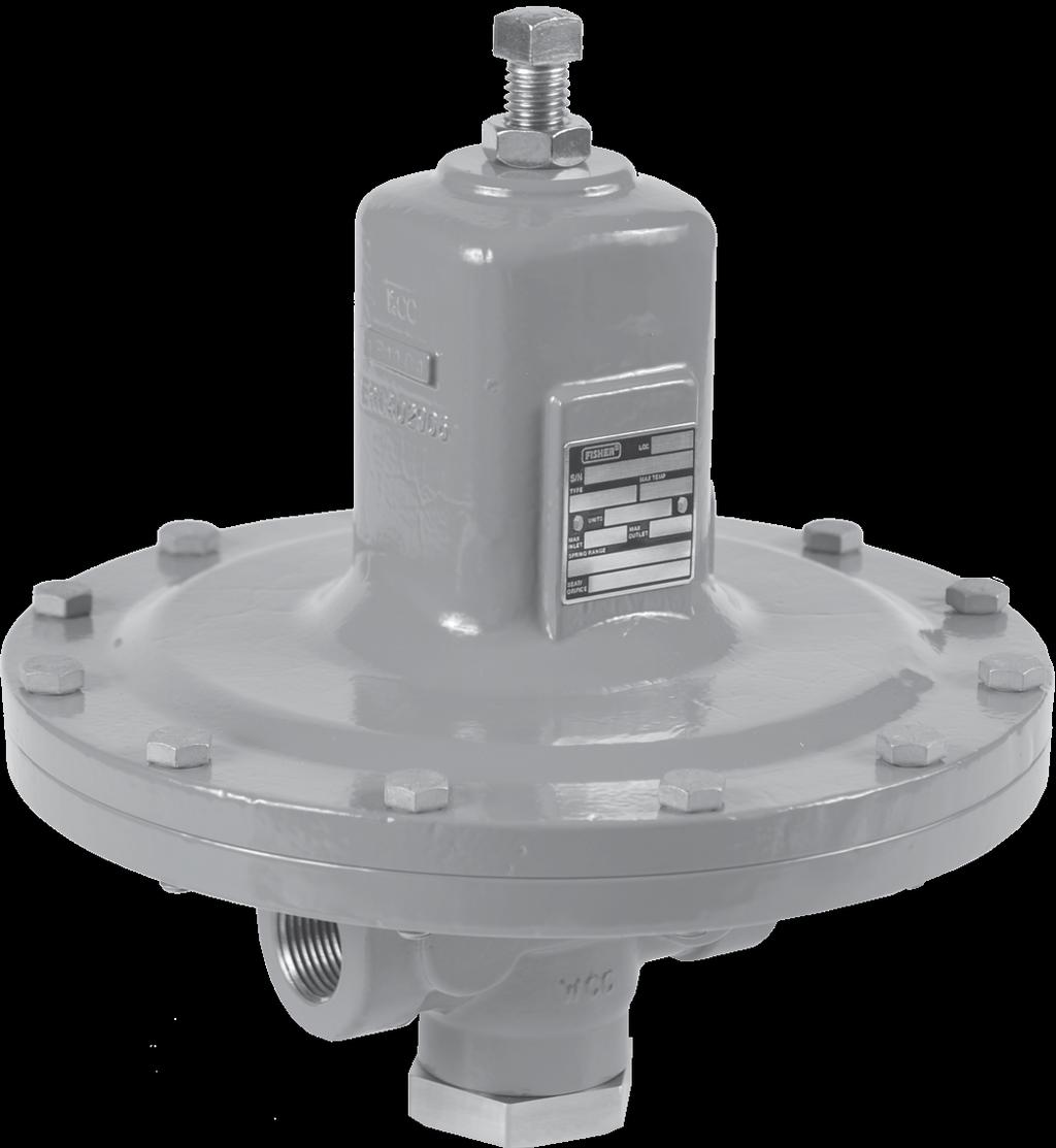


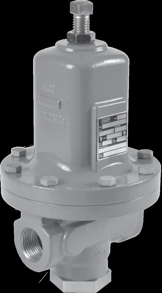

1 Instruction Manual D103588X012 October 2016 Backpressure Regulators, Relief and Differential Relief Valves P1757_1 Type MR98L P1753_1 TYPE MR98H Figure 1. Typical Backpressure Regulators, Relief and Differential Relief Valves
2 Specifications This section lists the specifications for the regulators. Factory specification such as type, maximum inlet pressure, maximum temperature, maximum outlet pressure, spring range, orifice size and seat material are stamped on the nameplate fastened on the regulator at the factory. Available Constructions Type MR98L: Backpressure regulator / relief valve for spring settings range from 2 to 38 psig / 0.14 to 2.6 bar, available for 1/4 to 1 in. / DN 25 body sizes only. Type MR98H: Backpressure regulator / relief valve for spring settings range from 5 to 200 psig / 0.34 to 13.8 bar Type MR98HH: Backpressure regulator / relief valve for spring settings range from 150 to 375 psig /10.3 to 25.9 bar Type MR98LD: Differential pressure relief valve for differential set pressures range from 2 to 38 psi / 0.14 to 2.6 bar with maximum inlet / outlet pressure up to 150 psi / 10.3 bar, available for 1/4 to 1 in. / DN 25 body sizes only. Type MR98HD: Differential pressure relief valve for differential set pressures from 5 to 200 psi / 0.34 to 13.8 bar with maximum inlet / outlet pressure up to 300 psi / 20.7 bar Type MR98HDP: Differential pressure relief valve for differential set pressures range from 5 to 200 psi / 0.34 to 13.8 bar with maximum inlet / outlet pressure up to 600 psi / 41.4 bar Type MR98HHD: Differential pressure relief valve for differential set pressures range from 150 to 375 psi / 10.3 to 25.9 bar with maximum inlet / outlet pressure up to 400 psi / 27.6 bar Body and Orifice Sizes 1/4 : in. / 7.22 mm 1/2 in. / DN 15: in. / mm 3/4 and 1 in. / DN 20 and 25: in. / mm 1-1/2 and 2 in. / DN 40 and 50: in. / 29 mm Body End Connections See Tables 1 and 2 Set Pressure Ranges (1) See Table 3 Maximum Cold Working Pressures of Body Size and Materials (1) See Table 4 Maximum Inlet, Outlet and Spring Case Pressure Ratings (1) See Table 4 Temperature Capabilities (1) See Table 5 Flow Coefficients Body size In. dn C v C g C 1 1/ / /4 and 1 20 and /2 and 2 40 and IEC Sizing Coefficients Body size In. dn X t F d f l K m 1/ / /4 and 1 20 and /2 and 2 40 and Pressure Registration Internal or External Shutoff Classification Per ANSI/FCI Metal Seats: Class IV Polytetrafluoroethylene (PTFE): Class IV Elastomer Seats: Class VI or better Sour Gas Service Capability Optional materials are available for applications handling sour gases. These constructions comply with the recommendations of NACE International Standards MR and MR0103. Optional materials are available to meet ANSI/ NACE MR0175/ISO API 614 Compliant Steel or constructions with trim meet API 614 Requirements. Approximate Weights MR98H Series: 1/4 : 5 lbs / 2.3 kg 1/2 in. / DN 15: 10 lbs / 4.5 kg 3/4 and 1 in. / DN 20 and 25: 22 lbs / 10 kg 1-1/2 and 2 in. / DN 40 and 50: 55 lbs / 25 kg MR98L Series: 1/4 : 7 lbs / 3.2 kg 1/2 in. / DN 15: 15 lbs / 6.8 kg 3/4 and 1 in. / DN 20 and 25: 35 lbs / 16 kg 1. The pressure/temperature limits in this Instruction Manual and any applicable standard limitation should not be exceeded. 2
3 Table 1. Types MR98L and MR98LD Regulators Body Constructions Body Material Body Size BODY CONSTRUCTION End Connection Style Gray Cast Iron WCC or LCC Steel CF8M Stainless Steel (1) CF3M Stainless Steel (1) Monel or Hastelloy C (1) 1/4 in. Without Control Line and Gauge Port SWE 1/2 in. / DN 15 Without Control Line and Gauge Port Welded CL150 RF Welded CL300 RF Welded PN 16/25/40 RF With Control Line but Without Gauge Port SWE Without Control Line and Gauge Port Welded CL150 RF Welded CL300 RF 3/4 in. / DN 20 With Control Line but Without Gauge Port Welded PN 16/25/40 RF With Gauge Port but Without Control Line Welded CL150 RF Welded CL300 RF Welded PN 16/25/40 RF SWE Without Control Line and Gauge Port Welded CL150 RF Welded CL300 RF 1 in. / DN 25 With Control Line but Without Gauge Port Welded PN 16/25/40 RF With Gauge Port but Without Control Line Welded CL150 RF Welded CL300 RF Welded PN 16/25/40 RF - Shaded areas indicate that the construction is available. - Blank areas indicate that you need to contact your local Sales Office for the availability of the constructions. 1. Meets the chemical and physical requirements of NACE MR and NACE MR0103. Monel is a mark owned by Special Metals Corporation. Hastelloy C is a mark owned by Haynes International, Inc. 3
4 Table 2. Types MR98H, MR98HD, MR98HH, MR98HDP and MR98HHD Regulators Body Constructions Body Material Body Size BODY Construction End Connection STYLE Gray Cast Iron (2) WCC or LCC Steel CF8M Stainless Steel (1) CF3MStainless Steel (1) Monel or Hastelloy C (1) Aluminum-Bronze 1/4 in. Without Control Line and Gauge Port SWE Welded CL150 RF Without Control Line and Gauge Port Welded CL300 RF Welded PN 16/25/40 RF 1/2 in. / DN 15 Integral CL150 RF Integral CL300 RF Integral PN 16/25/40 RF With Control Line but Without Gauge Port Welded CL150RF Welded CL300RF SWE Without Control Line and Gauge Port Welded CL150 RF Welded CL300 RF Welded PN 16/25/40 RF 3/4 in. / DN 20 With Control Line but Without Gauge Port Welded CL150 RF Welded CL300 RF With Gauge Port but Without Control Line Welded CL150 RF Welded CL300 RF Welded PN 16/25/40 RF SWE Welded CL150 RF Without Control Line and Gauge Port Welded CL300 RF Welded PN 16/25/40 RF Integral CL150 RF Integral CL300 RF 1 in. / DN 25 Integral PN 16/25/40 RF With Control Line but Without Gauge Port Welded CL150 RF Welded CL300 RF With Gauge Port but Without Control Line Welded CL150 RF Welded CL300 RF Welded PN 16/25/40 RF - Shaded areas indicate that the construction is available. - Blank areas indicate that you need to contact your local Sales Office for the availability of the constructions. 1. Meets the chemical and physical requirements of NACE MR and NACE MR Available for Types MR98H and MR98HD only. - continued - Monel is a mark owned by Special Metals Corporation. Hastelloy C is a mark owned by Haynes International, Inc. 4
5 Table 2. Types MR98H, MR98HD, MR98HH, MR98HDP and MR98HHD Regulators Body Constructions (continued) Body Material Body Size BODY Construction End Connection STYLE Gray Cast Iron WCC or LCC Steel CF8M Stainless Steel (1) CF3M Stainless Steel (1) Monel or Hastelloy C (1) Aluminum-Bronze SWE Without Control Line and Gauge Port Welded CL150 RF Welded CL300 RF Welded PN 16/25/40 RF 1-1/2 in. / DN 40 Types MR98H and MR98HD only With Control Line but Without Gauge Port Welded CL150 RF Welded CL300 RF With Gauge Port but Without Control Line Welded CL150 RF Welded CL300 RF Welded PN 16/25/40 RF SWE Welded CL150RF Without Control Line and Gauge Port Welded CL300RF Welded PN 16/25/40 RF Integral CL150 RF 2 in. / DN 50 Types MR98H and MR98HD only Integral CL300 RF Integral PN 16/25/40 RF With Control Line but Without Gauge Port Welded CL150 RF Welded CL300 RF With Gauge Port but Without Control Line Welded CL150 RF Welded CL300 RF Welded PN 16/25/40 RF - Shaded areas indicate that the construction is available. - Blank areas indicate that you need to contact your local Sales Office for the availability of the constructions. 1. Meets the chemical and physical requirements of NACE MR and NACE MR0103. Monel is a mark owned by Special Metals Corporation. Hastelloy C is a mark owned by Haynes International, Inc. 5
6 TYPE MR98L and MR98LD MR98H, MR98HD and MR98HDP MR98HH and MR98HHD BODY SIZE Table 3. Body Sizes, Pressure Ranges and Spring Information CONTROL PRESSURE RANGE (1) SPRING WIRE DIAMETER SPRING FREE LENGTH In. DN psig bar In. mm In. mm 1/ /2 15 3/4 and 1 3/4 and 1 20 and and 25 1/ /2 15 3/4 and 1 3/4 and 1 1-1/2 and 2 20 and and and 50 SPRING MATERIAL SPRING PART NUMBER SPRING COLOR 2 to to Zinc-plated steel 1E Yellow 6 to to Zinc-plated steel ERAA01888A0 Green 12 to to Powder-coated steel ERAA01889A0 Red 20 to to Powder-coated steel ERAA01929A0 Blue 2 to to Powder-coated steel ERCA04288A0 Yellow 6 to to Powder-coated steel ERAA01910A0 Green 12 to to Powder-coated steel ERAA01911A0 Red 20 to to Powder-coated steel ERAA02889A0 Blue 2 to to Powder-coated steel 1E Yellow 6 to to Powder-coated steel 1E Green 12 to to Powder-coated steel 1E Red 20 to to Powder-coated steel 1L Blue 2 to to Powder-coated 1E3989X0052 Yellow 6 to to K Unpainted 12 to to A8269X012 Unpainted 15 to to Zinc-plated steel 1E Yellow 25 to to Zinc-plated steel ERAA01888A0 Green 70 to to Powder-coated steel ERAA01889A0 Red 130 to to Powder-coated steel ERAA01929A0 Blue 15 to to Powder-coated steel ERCA04288A0 Yellow 25 to to Powder-coated steel ERAA01910A0 Green 70 to to Powder-coated steel ERAA01911A0 Red 130 to to Powder-coated steel ERAA02889A0 Blue 15 to to Powder-coated steel 1E Yellow 25 to to Powder-coated steel 1E Green 70 to to Powder-coated steel 1E Red 130 to to Powder-coated steel 1L Blue 15 to to Powder-coated 1E3989X0052 Yellow 25 to to K Unpainted 70 to to A8269X012 Unpainted 5 to to Powder-coated steel 1E Dark gray 20 to to Powder-coated steel ERCA04290A0 Black with light blue stripe 50 to to Powder-coated steel ERAA01893A0 Light gray 75 to to Powder-coated steel 1P7888X0022 Black 1/ to to Powder-coated steel 1N Unpainted 1/ to to Powder-coated steel 1N Unpainted 3/4 and 1 20 and to to Chromium-silicon steel 1N9441X0022 Light gray 1. All springs may be backed off to 0 psig / 0 bar. However, highest capacities and best performances are obtained by using these springs in their recommended ranges. 6
7 Regulator Type MR98L/LD MR98H/ MR98HD MR98HDP (4)(5) MR98HH/ MR98HHD (4) Table 4. Maximum Cold Working Pressures of Body Size and Materials (1)(2) Body Size Body and Spring Case Materials Maximum Maximum Maximum Inlet Pressure (3) Outlet Pressure Spring Case Pressure In. DN psig bar psig bar psig bar 1/4 1/2, 3/4, , 20, 25 1/2, 3/4, 1 15, 20, 25 1/4, 1/2, 3/4, 1, 1-1/2, 2 1/2, 3/4, 1, 1-1/2, 2 1/4, 1/2, 3/4, 1, 1-1/2, 2 1/2, 3/4, 1, 1-1/2, 2 1/4, 1/2, 3/4, , 20, 25, 40, 50 15, 20, 25, 40, , 20, 25, 40, 50 15, 20, 25, 40, , 20, 25 1/2, 3/4, 1 15, 20, 25 Gray cast iron Steel Monel Hastelloy C Gray cast iron Steel Monel Hastelloy C Aluminum-Bronze Steel Monel Hastelloy C Aluminum-Bronze Steel Monel Hastelloy C Aluminum-Bronze The pressure/temperature limits in this Installation Manual and any applicable standard limitation should not be exceeded. 2. Temperature, trim material and/or the body end connection may decrease these maximum pressures. 3. Maximum inlet pressure equals set pressure plus build-up. 4. Maximum differential pressure between inlet pressure and loading pressure should never exceed 300 psig / 20.7 bar. 5. Meets API 614 requirements (with trim). Table 5. Temperature Capabilities (1)(2) Material Seat Diaphragm O-ring Diaphragm Protector Temperature F C Nitrile (NBR) -40 to to 82 Neoprene (CR) -40 to to 82 Fluorocarbon (FKM) (3) 0 to 300, Limited to 200 F for hot water -18 to 149, Limited to 93 C for hot water Ethylenepropylene (EPDM) 20 to to 135 Perfluoroelastomer (FFKM) 0 to to 218 PTFE -40 to to 204 Metal -40 to to 232 Body Material Temperature F C Gray cast iron -20 to to 208 WCC Steel (4) -20 to to 232 LCC Steel (4) -40 to to 232 (4), Monel or Hastelloy C -40 to to The pressure/temperature limits in this Instruction Manual and any applicable standard limitation should not be exceeded. 2. Pressure and/or the body end connection may decrease these maximum temperatures. 3. Not for use on steam service. 4. Meets API 614 requirements (with trim). Monel is a mark owned by Special Metals Corporation. Hastelloy C is a mark owned by Haynes International, Inc. 7
8 ! Warning Failure to follow these instructions or to properly install and maintain this equipment could result in an explosion, fire and/or chemical contamination causing property damage and personal injury or death. Fisher backpressure regulators, relief and differential relief valves must be installed, operated and maintained in accordance with federal, state and local codes, rules and regulations and Emerson Process Management Regulator Technologies, Inc. (Emerson) instructions. If a leak develops or if the outlet continually vents gas, service to the unit may be required. Failure to correct trouble could result in a hazardous condition. Only a qualified person shall install or service the unit. Installation, operation and maintenance procedures performed by unqualified person may result in improper adjustment and unsafe operation. Either condition may result in equipment damage or personal injury. Call a qualified person when installing, operating and maintaining the backpressure regulators, relief and differential relief valves. Introduction Scope of the Manual This manual provides instructions for the installation, adjustment, maintenance and parts ordering information of backpressure regulators, relief and differential relief valves. Instructions and parts lists for other equipment mentioned in this Instruction Manual are found in separate manuals. Product Description The backpressure regulator, relief and differential relief valves are suitable for multiple fluid mediums including liquid, gas, air and steam services. Typical applications include use in but not limited to wash tanks, small heaters, fuel and oil lines, air supply system, test fixtures and sterilizers. Backpressure Regulator / Pressure Relief Valve Types MR98L, MR98H and MR98HH regulators are direct-operated backpressure regulator/relief valve for pressure control requiring constant outlet pressures between 2 to 375 psig / 0.14 to 25.9 bar. Differential Pressure Relief Valve Types MR98LD, MR98HD, MR98HDP and MR98HHD regulators are direct-operated differential relief valve with differential pressure range from 2 to 600 psig / 3.4 to 41.4 bar. See Tables 1 through 5 for detailed breakdown of the various construction offerings. Principle of Operation Relief or backpressure valves respond to changes in upstream pressure. Pressure changes register under the diaphragm (see Figure 2) through a registration hole in the valve body or through an external control line. When the pressure increases above the spring setting, the pressure underneath the diaphragm overcomes the spring compression. This causes the valve plug to move away from the orifice. The flow path through the valve is open and excess pressure is vented. When upstream pressure drops below setpoint, the valve closes. Differential relief valves are used to maintain a differential pressure between the controlled pressure and loading pressure of a system. The spring setting determines the differential. The differential relief valve responds to both controlled pressure and loading pressure and opens or closes as these pressures change. If the loading pressure increases, pressure on the upper side of the diaphragm increases. The valve plug moves closer to the orifice and restricts the flow through the relief valve. When loading pressure decreases, pressure on the upper side of the diaphragm decreases. This allows the valve plug to move away from the orifice and allow more flow through the differential relief valve (to atmosphere or back into the system). The differential relief valve opens and closes in response to changes in the controlled pressure. In this way, the differential pressure between the controlled and uncontrolled pressures is maintained. 8
9 adjusting screw control spring vent diaphragm valve plug orifice CONTROL LINE TAP M1240_08/2013 M1239_08/2013 TYPE MR98H WITH INTERNAL PRESSURE REGISTRATION INLET PRESSURE OUTLET PRESSURE ATMOSPHERIC PRESSURE BACK VIEW OF 1/2 IN. / DN 15 TYPE MR98H WITH EXTERNAL PRESSURE REGISTRATION SIDE AND INTERNAL VIEW OF 3/4 TO 2 IN. / DN 20 TO 50 TYPE MR98H WITH EXTERNAL PRESSURE REGISTRATION (ALSO TYPICAL OF TYPE MR98L, 1/2 TO 2 IN. / DN 15 TO 50 BODIES) Metal diaphragms Spring Metal diaphragm Spring gasket gasket For type MR98H with two metal diaphragms (also typical of types MR98L and MR98HH except for type MR98l, 1/4 BODY, 2 to 7 psi / 0.1 TO 0.48 bar range) Type MR98L (1/4 BODY, 2 to 7 psi / 0.14 TO 0.48 bar range) with one metal diaphragm Figure 2. Operational Schematics 9
10 Handwheel Control spring Diaphragm Loading pressure inlet tap Valve plug Orifice M1242_08/2013 INLET PRESSURE OUTLET PRESSURE LOADING PRESSURE TYPE MR98HD WITH INTERNAL PRESSURE REGISTRATION CONTROL LINE TAP TYPE MR98HD WITH EXTERNAL PRESSURE REGISTRATION Spring Metal diaphragms Gasket for types MR98HD, MR98LD, MR98HDP and MR98HHD with two metal diaphragms, assemble diaphragm gaskets under and above the metal diaphragms as shown above Figure 2. Operational Schematics (continued) Low pressure (for loading) Controlled high pressure TYPE MR98lD Figure 3. Installation Schematics for Types MR98LD and MR98HD Relief Valves 10
11 loading pressure high pressure relief outlet and optional piping to system uncontrolled low pressure controlled high pressure pump TYPE MR98HD Figure 3. Installation Schematics for Types MR98LD and MR98HD Relief Valves (continued) Installation! Warning Personal injury or system damage may result if this backpressure regulator, relief or differential relief valve is installed where service conditions could exceed the limits given on the Specifications section and/or regulator nameplate. Additionally, physical damage to the backpressure regulator or relief valve may result in personal injury or property damage due to escaping of accumulated gas. To avoid such injury and damage, install the backpressure regulator or relief valve in a safe location. Under enclosed conditions or indoors, escaping gas may accumulate and be an explosion hazard. In this case, the vent should be piped outdoors. For regulator constructions with a spring case vent, the vent should be kept open to permit free flow of gas to the atmosphere. Protect openings against entrance of rain, snow, insects or any other foreign material that may plug the spring case vent or vent line. 11
12 Before installing the regulator: Unpack the backpressure regulator or relief valve and remove the protective shipping plugs from the end connections of the body and the pressure connection in the spring case. Check the backpressure regulator or relief valve and make sure it has not been damaged or collected foreign material during shipping. Remove any debris or dirt in the tubing and the pipeline. Apply pipe compound to the external pipe thread for bodies or use appropriate gaskets for flanged bodies. Make sure gas flow through the backpressure regulator or relief valve is in the same direction as the arrow on the body. For a differential relief valve, the design of the valve isolates the diaphragm and pressure loading spring case from the main flow stream. The higher pressure is measured inside the body through a registration hole on the inlet side of the body or through the external control line. If loading pressure is required, connect the loading pressure line to the 1/4 connection in the spring case. If loading pressure is not required, vent this connection to the atmosphere. Overpressure Protection! Warning Overpressuring any portion of this equipment may result in equipment damage, leaks in the relief valve/ backpressure regulator or personal injury due to bursting of pressurecontaining parts. Relief, differential relief or backpressure ranges are from 2 to 375 psig / 0.14 to 25.9 bar. The individual spring range of your valve is stamped on the nameplate. Maximum inlet pressure depend upon body materials and temperatures. See Specifications section or the maximum inlet pressure of the valve and the maximum spring case loading pressures stamped on the nameplate of Types MR98LD, MR98HD, MR98HDP and MR98HHD. The valve should be inspected for damage after any overpressure condition. Vents and Relief Valve Outlet! Warning If using an backpressure regulator, relief or differential relief valve on hazardous or flammable gas service, personal injury and property damage could occur due to fire or explosion of vented gas that may have accumulated. To prevent such injury or damage, provide piping or tubing to vent the gas to a safe, well-ventilated area. All vents should be kept open to permit free flow of gas to the atmosphere. Protect openings against entrance of rain, snow, insects or any other foreign material that may plug the vent or vent line. If remote venting is necessary, an optional tapped vent in the spring case is available. Install remote vent lines in the spring case and outlet openings. The vent lines must have the largest practical diameter and be as short as possible with a minimum number of bends or elbows. Install the vent line according to applicable federal, state and local codes and regulations. Startup Note The Specifications section and Tables 4 shows the maximum inlet and the differential pressures for specific constructions. Use pressure gauges to monitor inlet pressure, outlet pressure and any loading pressure during startup. 12
13 Special care should be taken during startup when using a differential relief valve to ensure the differential pressure between the inlet and spring case of the regulator does not exceed the maximum allowable value. Key numbers are shown in Figures 4 through Check that proper installation is completed and downstream equipment has been properly adjusted. 2. Make sure all block and vent valves are closed. 3. Decompress the control spring by turning the adjusting screw (for Types MR98L, MR98H and MR98HH) or handwheel (for Types MR98LD, MR98HD, MR98HDP and MR98HHD) counterclockwise. 4. Slowly open the valves in the following order: a. Loading supply and control line valve(s), if used b. Inlet block valve c. Outlet block valve 5. Set the regulator to the desired set pressure according to the Adjustment procedure. Adjustment Each unit is factory set for the pressure setting specified on the order or at the mid-point of the spring range. The allowable spring range is stamped on the nameplate. If a pressure setting beyond the indicated range is required, replace with the appropriate spring. Be sure to label the regulator/valve to indicate the new pressure range. Always use a pressure gauge to monitor pressure when making adjustments. All regulator springs can be backed off to zero pressure. Recommended set pressure ranges available, maximum inlet pressures and temperatures and color codes of the respective springs are shown in the Specifications section and Table 3. Types MR98L, MR98H and MR98HH 1. Loosen the jam nut (key 17, Figures 4, 6, 7 and 10). 2. To increase the set pressure or pressure setting, turn the adjusting screw (key 15) clockwise. Turn the adjusting screw counterclockwise to decrease the set pressure or pressure setting. 3. Tighten the jam nut (key 17). Types MR98LD, MR98HD, MR98HDP and MR98HHD Turn the handwheel (key 38, Figures 5, 8 and 9) clockwise to increase differential pressure setting. Turn the handwheel counterclockwise to decrease the differential pressure setting. Shutdown Relief Valve 1. Close the upstream shutoff valve to the regulator inlet. 2. Close the downstream shutoff valve to the regulator outlet. 3. Slowly open the downstream vent valve to vent downstream pressure. 4. Leave the downstream vent valve open to vent inlet pressure and to release all remaining pressure in the regulator by opening the upstream vent valve or by turning the adjusting screw fully counterclockwise. Differential Valve (Pressure-Loaded System) 1. Close the upstream shutoff valve to the regulator inlet. 2. Close the downstream shutoff valve to the regulator outlet.! Warning To avoid damage of internal parts from a pressure-loaded actuator, carefully vent the regulator spring case pressure while monitoring both inlet and loading pressure to ensure the differential pressure between inlet and loading does not exceed 300 psid / 20.1 bar d. 3. Vent the loading pressure slowly to release pressure in the spring case. 4. Slowly open the downstream vent valve to vent downstream pressure. 5. Leave the downstream vent valve open to vent inlet pressure and to release all remaining pressure in the regulator by opening the upstream vent valve or by turning the adjusting screw fully counterclockwise. 13
14 Body size Spring case bolts (1) Orifice Valve plug guide Bottom plug In. DN Ft-Lbs N m Ft-Lbs N m Ft-Lbs N m Ft-Lbs N m 1/4 1/2 3/4 and 1 1-1/2 and and and 50 6 to 8 10 to to to 50 8 to to to to 68 Table 6. Torque Specifications 6 to 8 34 to to to to to to to to to to to to to to to to to to to to to to to Reduce spring case bolt s torque by 30% when using Ethylenepropylene (EPDM) diaphragms. Note: Pusher post lock nut (key 31) should be installed with an additional 1/8 to 1/4 turn when washer is flat. See step 10 in the Disassembly to Replace Diaphragm and Seats section or detailed instruction. Backpressure Regulator 1. Close the upstream shutoff valve to the regulator inlet. 2. Close the downstream shutoff valve to the regulator outlet. 3. To avoid internal damage due to reverse pressurization of main valve components, bleed backpressure regulator inlet pressure first before bleeding outlet pressure. Maintenance! Warning To avoid personal injury, property damage or equipment damage caused by sudden release of pressure or explosion of accumulated gas, do not attempt any maintenance or disassembly without first isolating the relief valve or regulator from system pressure and relieving all internal pressure from the relief valve or regulator. To avoid possible personal injury from spring or pressure-loaded actuator, make sure that the adjusting screw is completely backed off or the spring case pressure is vented prior to disassembly. Otherwise, the spring load or loading pressure could forcefully eject the spring case. Relief valves or regulators that have been disassembled for repair must be tested for proper operation before being returned to service. Only parts manufactured by Emerson should be used for repairing Fisher relief valves and regulators. Due to normal wear or damage that may occur from external sources, this relief valve or backpressure regulator should be inspected and maintained periodically. The frequency of inspection and replacement of parts depends upon the severity of service conditions or the requirement of local, state and federal rules and regulations. Due to normal wear and damage that may occur from external sources, relief valve parts such as the O-rings, gaskets, diaphragm, orifice and valve plug should be inspected periodically and replaced as necessary. The frequency of inspection and replacement depends upon the severity of service conditions or the requirements of state and federal laws. Instructions are given below for disassembly of the. These valves do not have to be removed from the pipeline to inspect internal parts. Suitable lubricants are indicated on the assembly drawings. Apply the recommended lubricants as the relief valve is being reassembled. Refer to Figures 4 to 10 while servicing the relief valve. Flange Cap Screw Torque Inspection Retorquing of spring case cap screws may be necessary for some regulators after a period of use. Retorque the cap screws as follows: 1. Shut down the relief valve or backpressure regulator. Refer to Shutdown section for the proper procedure. 2. Retighten the cap screws (key 16) in a crisscross pattern. See Table 6 for proper torque values. 3. Follow the Startup section to repressurize the relief valve or backpressure regulator. 4. Refer to the Disassembly to Replace Diaphragm and Seats section as needed. 14
15 Body Size Type Spring Range Diaphragm Material Number of Diaphragm Neoprene (CR) 1 All Fluorocarbon (FKM) 2 MR98L and MR98LD Ethylenepropylene (EPDM) 1 2 to 7 psi / 0.1 to 0.5 bar Metal 1 1/4 All except 2 to 7 psi / 0.1 to 0.5 bar Metal 2 Neoprene (CR) 1 MR98H, MR98HH, Fluorocarbon (FKM) 2 MR98HD, MR98HDP All Ethylenepropylene (EPDM) 1 and MR98HHD Metal 2 1/2 to 2 in. / DN 15 to 50 All Table 7. Number of Diaphragms Required All Neoprene (CR) 1 Fluorocarbon (FKM) 2 Ethylenepropylene (EPDM) 1 Metal 2 Disassembly to Replace Diaphragm and Seats Caution Metal diaphragms have thin sharp edges. To avoid hand cuts, be careful when handling the diaphragm, particularly the diaphragm edge. If the relief valve is leaking, the diaphragm may be ruptured or the seating surfaces nicked or scratched. Proceed as follows to inspect or replace the diaphragm, orifice and valve plug. 1. Shut down the backpressure regulator or relief valve. Refer to Shutdown section for the proper procedure. 2. For Types MR98LD, MR98HD, MR98HDP and MR98HHD: Release all spring compression by turning the adjusting screw or handwheel (key 33 or 38) counterclockwise until it turns freely without resistance from the spring. For Types MR98L, MR98H and MR98HH: Relieve the spring tension by loosening the jam nut (key 17) and turning the adjusting screw (key 15) counterclockwise. 3. Remove cap screws (key 16) and lift off the spring case (key 2), upper spring seat (key 9) and relief valve spring (key 11). Lift out the diaphragm unit which includes the lock nut (key 31), lock washer (key 28), pusher post (key 10), gasket (key 29), lower spring seat (key 8), diaphragm (key 12), diaphragm head (key 21 for Types MR98L and MR98LD, all body sizes and for Types MR98H, MR98HD and MR98HDP, 1-1/2 and 2 in. / DN 40 and 50 body sizes), valve plug (key 4) and Type MR98HD has another washer (key 58) and an O-ring (key 45). 4. Check the orifice (key 3) for wear or damage. If it needs to be replaced, unscrew the valve plug guide (key 7) and then the orifice. The valve plug (key 4) can be removed by sliding it off of the pusher post (key 10). 5. Place a small amount of sealant on the threads of the orifice (key 3) and valve plug guide (key 7) and reinstall these to the body (key 1). See Table 6 for torque specifications. 6. To replace the valve plug O-ring (key 53), remove the machine screw (key 24) and O-ring retainer (key 25) from the plug. Remove and replace the O-ring. 7. Separate the remainder of the diaphragm unit parts. Take the lock nut (key 31) off of the pusher post (key 10). Slide off the lock washer (key 28), lower spring seat (key 8), diaphragm head (key 21) for Types MR98L and MR98LD, all body sizes and for Types MR98H and MR98HD, 1-1/2 and 2 in. / DN 40 and 50 body sizes), diaphragm (key 12), washer (key 58) and gasket (key 29). 8. Slip the valve plug (key 4) onto the pusher post (key 10). Place a gasket (key 29) on the shaft of the pusher post over the threaded portion until it rests on the base of the post. If elastomer diaphragm (key 12) is used, place a metal washer (key 58) on top of the gasket. For Type MR98H, 1-1/2 to 2 in. / DN 40 to 50 with metal diaphragm, place another gasket on the shaft of the pusher post until it rests on the bottom diaphragm head (key 21), see Figure 7. 15
16 Note If a metal diaphragm is to be replaced by an elastomer diaphragm or an elastomer diaphragm by a metal diaphragm, a new pusher post is required. Each diaphragm material requires a different pusher post length and make sure the proper number of metal or elastomer diaphragm that will be used is followed. Refer to the Parts List section or Table 7 for the correct number of diaphragm to be used. 9. See Figures 4 to 10. For the metal diaphragms (key 12), replace the large diaphragm gasket (key 19) on the surface of the body (key 1) that will support the diaphragms. There will be two diaphragms used per regulator, except for 1/4 Types MR98L and MR98LD with 2 to 7 psi / 0.1 to 0.5 bar spring range, which use only one metal diaphragm. The raised surfaces of the metal diaphragms should be placed in the unit so that they are facing toward the assembler (toward the spring) except only when one diaphragm is being used then the raised surface should be facing down (towards the body) (see Figure 2). For elastomer diaphragms, the printed side should be facing upwards when installed. 10. Slip the lower spring seat (key 8) and lock washer (key 28) back onto the pusher post (key 10). Lubricate the threads of the pusher post and tighten the pusher post lock nut (key 31) until the lock washer is flat and then turn the nut an additional 1/8 to 1/4 turn. Return the diaphragm (key 12), spring seat and pusher post assembly to the body (key 1). 11. Set the relief valve spring (key 11) in the lower spring seat and place the upper spring seat (key 9) on the spring. 12. Put the spring case (key 2) over the spring (key 11) and onto the body (key 1). Tighten the cap screws (key 16) finger tight only. 13. To ensure proper slack in the diaphragm (key 12), apply some spring compression by turning the adjusting screw (key 15) or handwheel (key 38) clockwise. Finish tightening the cap screws. See Table 6 for recommended torque values. Replacement or Maintenance of Bottom Plug O-ring If there is any external leakage from the bottom plug the bottom plug O-ring could be worn out or damaged. Proceed as follows to check and/or replace it. 1. Shut down the regulator. Refer to Shutdown section for the proper procedure. 2. Unscrew the bottom plug (key 5) from the body (key 1). Inspect the bottom plug seal (key 63) for damage. Replace the bottom plug seal if damage is noted. Lightly lubricate the bottom plug O-ring or graphite ring before installing it onto the bottom plug. 3. Reassemble the regulator in the reverse order of the above steps. When installing the bottom plug (key 5), coat the threads and sealing surface with anti-seize compound to ensure an adequate metal-to-metal seal. Reference Table 6 for proper torque values. Disassembly to Replace Packing (For Types MR98LD, MR98HD, MR98HDP and MR98HHD) Leakage around the adjusting screw may be caused by worn packing in the stuffing box. To check the packing, perform the following procedures. 1. Before returning the upper spring case (key 2) to the body (key 1), replace the packing (key 36) in the packing/stuffing box (key 32). 2. Take out the machine screw (key 41) and lift off the washer (key 44) and handwheel (key 38). 3. Unscrew the packing/stuffing box (key 32). Unscrew the packing/stuffing box nut (key 35) and take it and the packing follower (key 34) off of the adjusting screw (key 33). 4. Unscrew and pull the adjusting screw (key 33) out through the bottom of the packing/stuffing box (key 32). 5. Pull out the packing (key 36) and replace it. Replace the packing/stuffing box gasket (key 37). 16
17 6. Reassemble the packing/stuffing box (key 32) unit by returning the adjusting screw (key 33) to the inside of the stuffing box. Slip the packing follower (key 34) onto the adjusting screw and into the stuffing box. Screw on the packing nut (key 35). See Table 6 for torque specifications. 7. Put the packing/stuffing box (key 32) onto the spring case (key 2). Set the handwheel (key 38) and washer (key 44) on the adjusting screw (key 33) and screw in the machine screw (key 41). 8. Set the spring (key 11) and upper spring seat (key 9) over the lower spring seat (key 8). Place the spring case (key 2) on the body (key 1), tightening the cap screws (key 16) finger-tight only. 9. To ensure proper slack in the diaphragm (key 12), apply some spring compression by turning the adjusting screw (key 15) or handwheel (key 38) clockwise. Tighten the cap screws (key 16). Parts Ordering When corresponding with your local Sales Office about this equipment, always reference the equipment serial number stamped on the nameplate. When ordering replacement parts, specify the complete 11-character part number of each required part as found in the following parts list. Separate kits containing all recommended spare parts are available. Note In this parts list, parts marked NACE are intended for corrosion-resistant service as detailed in the NACE International Standard MR0175 and NACE MR0103. Optional materials are available to meet ANSI/NACE MR0175/ISO 15156, please contact your local Sales Office for special ordering instructions. Parts List Key Description part Number Parts Kit (included are keys 3, 4, 12, 29, 59 and 63) Types MR98H, MR98HD, MR98HH and MR98HDP With diaphragm and trim 1/4 Body Size RMR98HX0042 RMR98HX0052 RMR98HX0062 RMR98HX0082 With Neoprene (CR) diaphragm and Nitrile (NBR)/416 trim 1/4 Body Size RMR98HX0012 RMR98HX0022 RMR98HX0032 RMR98HX0072 Types MR98L and MR98LD With diaphragm and plug 1/4 Body Size RMR98LX0042 RMR98LX0052 RMR98LX0062 With Neoprene (CR) and Nitrile (NBR)/Brass Disk 1/4 Body Size RMR98LX0012 RMR98LX0022 RMR98LX Body See Following Tables 2 Spring Case See Following Tables 3* Orifice Metal-to-metal seat 1/4 Body Size 416 GF04856X , NACE GF04856X032 GF04856X052 GF04856X GF04841X , NACE GF04841X032 Alloy 6, NACE GF04841X062 GF04841X052 GF04841X GF04821X , NACE GF04821X032 Alloy 6, NACE GF04821X062 GF04821X052 GF04821X042 *Recommended Spare Part Monel is a mark owned by Special Metals Corporation. Hastelloy C is a mark owned by Haynes International, Inc. 17
18 Key Description part Number 3* Orifice (continued) Metal-to-metal seat (continued) 416 GF04896X , NACE GF04896X032 Alloy 6, NACE GF04896X062 GF04896X052 GF04896X042 1/4 Body Size 416 GF05036X , NACE, Oxygen Service GF05036X GF05552X , NACE, Oxygen Service GF05552X032 GF05552X GF04824X , NACE, Oxygen Service GF04824X032 GF04824X GF05513X , NACE, Oxygen Service GF05513X032 GF05513X052 4* Valve Plug See Following Tables 5 Bottom Plug 1/4 Body Size 416 GF05500X , NACE, Oxygen Service GF05500X032 GF05500X052 GF05500X GF05532X , NACE, Oxygen Service GF05532X032 GF05532X052 GF05532X GF05496X , NACE, Oxygen Service GF05496X032 GF05496X052 GF05496X GF05511X , NACE, Oxygen Service GF05511X032 GF05511X052 GF05511X042 7 Valve Plug Guide 1/4 Body Size 416 GF04882X , NACE, Oxygen Service GF04882X032 GF04882X052 GF04882X GF05534X , NACE, Oxygen Service GF05534X032 GF05534X052 GF05534X GF05529X , NACE, Oxygen Service GF05529X032 GF05529X052 GF05529X GF05539X , NACE, Oxygen Service GF05539X032 GF05539X052 GF05539X042 Key Description part Number 8 Lower Spring Seat, NACE Types MR98L, MR98H, MR98LD, MR98HD and MR98HDP 1/4 Body Size Aluminum (1) Aluminum (1) Aluminum (1) Steel (1) Types MR98HH, MR98HDP and MR98HHD 1/4 Body Size Aluminum (1) Aluminum (1) Steel (1) 9 Upper Spring Seat, NACE Types MR98L, MR98H, MR98LD, MR98HD and MR98HDP 1/4 Body Size Steel (1) Steel (1) Steel (1) Steel (1) Types MR98HH and MR98HHD 1/4 Body Size Steel (1) Steel (1) Steel (1) 1L L3446X0012 1L L3397X0012 1L L3427X0012 1P P7877X0012 1N N9420X0012 1N N9430X0012 1N N9438X0012 ERCA00383A0 ERCA00383A1 ERCA00823A0 ERCA00823A1 1E E3987X0012 1P P7876X0012 1N N9421X0012 ERCA00430A0 ERCA00430A1 1N N9439X Pusher Post Composition Diaphragm 1/4 Body Size 416 1L , NACE, Oxygen Service 1L L3456X0032 1L3456X0022 Metal Diaphragm 416 ERCA01344A0 316, NACE, Oxygen Service ERCA01344A1 ERCA01344A3 ERCA01344A2 *Recommended Spare Part 1. Part meets NACE requirements only for applications in which the part is not exposed to sour gas. Monel is a mark owned by Special Metals Corporation. Hastelloy C is a mark owned by Haynes International, Inc. 18
19 Key Description part Number 10 Pusher Post (continued) Metal Diaphragm (continue) 416 1L , NACE, Oxygen Service 1L L3438X0012 1L3438X P , NACE, Oxygen Service 1P P7884X0012 1P7884X0022 1/4 Body Size 416 GF04910X , NACE, Oxygen Service GF04910X032 GF04910X052 GF04910X ERCA01343A0 316, NACE, Oxygen Service ERCA01343A1 ERCA01343A3 ERCA01343A L , NACE, Oxygen Service 1L L L P , NACE, Oxygen Service 1P P7883X0012 1P7883X00A2 11 Control Spring, NACE (1) See Table 3 12* Diaphragm See Following Tables 13 Nameplate Diaphragm Protector, PTFE, NACE Types MR98L and MR98LD 1/4 Body Size 11A5132X012 11A5133X012 11A5137X012 Types MR98H, MR98HD, MR98HH, MR98HDP and MR98HHD 1/4 Body Size 11A5135X012 11A5136X012 11A5134X012 11A5527X Adjusting Screw, NACE (1) Square Head Adjustment 1/4 Body Size GF05533X012 Types MR98L and MR98H GF05553X012 Type MR98HH ERAA02340A0 Types MR98L and MR98H GF05543X012 Type MR98HH ERCA01483A0 GF05522X012 Sealed Square Head Adjustment GF05553X012 GF05543X012 GF05522X012 Key Description part Number 15 Adjusting Screw, NACE (1) (continued) Square Head Adjustment 1/4 Body Size GF05533X022 Types MR98L and MR98H GF05553X022 Type MR98HH ERAA02340A1 Types MR98L and MR98H GF05543X022 Type MR98HH ERCA01483A1 GF05522X022 Handwheel ERAA02331A0 16 Cap Screws, NACE (1) Types MR98L and MR98LD 1/4 Body Size Steel (10 required) (10 required) Steel (10 required) (10 required) Steel (12 required) (12 required) Types MR98H, MR98HD, MR98HH and MR98HHD 1/4 Body Size Steel (6 required) (6 required) B8M Class 2 (6 required) Steel (8 required) (8 required) Steel (8 required) (8 required) Steel (8 required) (8 required) Type MR95HDP 1/4 Body Size Steel (6 required) (6 required) Steel (8 required) (8 required) Steel (8 required) (8 required) Steel (8 required) (8 required) ERCA00651A0 ERCA00651A1 ERCA00100A0 ERCA00100A1 GF05446X012 GF05446X022 ERCA04149A0 ERCA04149A1 ERCA04149A3 ERCA00100A0 ERCA00100A1 GF05446X012 GF05446X022 ERCA00601A0 ERCA00601A3 ERCA04149A2 ERCA04149A3 ERCA00100A2 ERCA00100A3 GF05446X032 GF05446X042 ERCA00601A2 ERCA00601A3 17 Jam Nut, NACE (1) Square Head Adjustment 1/4 Body Size ERCA00652A0 ERCA00380A0 GF05453X012 ERCA00633A0 Square Head Adjustment 1/4 Body Size ERCA00652A1 ERCA00380A1 GF05453X022 ERCA00633A1 *Recommended Spare Part 1. Part meets NACE requirements only for applications in which the part is not exposed to sour gas. Monel is a mark owned by Special Metals Corporation. Hastelloy C is a mark owned by Haynes International, Inc. 19
20 Key Description part Number 17 Jam Nut, NACE (1) (continued) Sealed Square Head Adjustment ERCA00380A0 GF05453X012 ERCA00633A0 Tee Handle Adjustment 1/4 Body Size ERCA00652A0 GF05453X012 ERCA00633A0 Handwheel Adjustment ERCA00380A0 18 Drive Screw (4 required), NACE ERAA01884A0 19* Diaphragm Gasket (2 required for pressure loaded spring case) 302 diaphragm Types MR98L and MR98LD 1/4 Body Size ERCA00655A0 ERCA00491A0 ERCA00556A0 Types MR98H, MR98HD, MR98HH, MR98HDP and MR98HHD 1/4 Body Size 1E ERCA00485A0 ERCA00510A0 ERCA00526A Oxygen Service diaphragm Type MR98L 1/4 Body Size ERCA00655A2 ERCA00491A2 ERCA00556A2 Types MR98H and MR98HH 1/4 Body Size 1E3931X0022 ERCA00485A2 ERCA00510A2 ERCA00526A Steam Service, Monel and Hastelloy C Diaphragms Types MR98L and MR98LD 1/4 Body Size ERCA00655A1 ERCA00491A1 ERCA00556A1 Types MR98H, MR98HD, MR98HH, MR98HDP and MR98HHD 1/4 Body Size 1E3931X0012 ERCA00485A1 ERCA00510A1 ERCA00526A1 21 Diaphragm Head 1/4 Body Size Steel, NACE (1), NACE Steel, NACE (1), NACE Steel, NACE (1) 1L L3455X0012 1L L3396X0012 1L , NACE 1L3421X0012 (2 required) 416 ERCA00578A0 316, NACE, Oxygen Service ERCA00578A1 ERCA00578A3 ERCA00578A2 Key Description part Number 22 Adjusting Screw Assembly, NACE Tee Handle Adjustment 1/4 Body Size ERAA01707A0 ERAA01716A0 ERAA01694A0 23 Handwheel, NACE, (1/2 in. / DN 15 Body) ERAA02088A0 24 Machine Screw 1/4 Body Size 416 GF05033X , NACE, Oxygen Service GF05033X J4159X , NACE, Oxygen Service 1J4159X0012 1J4159X L , NACE, Oxygen service 1L3435X0012 1L3435X P , NACE, Oxygen Service 1P P7886X O-ring Retainer 1/4 Body Size 416 GF05031X , NACE, Oxygen Service GF05031X GF05078X , NACE, Oxygen Service GF05078X032 GF05078X L , NACE, Oxygen Service 1L L3430X Seat Retainer 416 ERCA00377A0 316, NACE, Oxygen Service ERCA00377A1 ERCA00377A3 28 Lockwasher, NACE (1) 1/4 and s Steel ERAA01919A0 ERAA01919A1 Steel 1H H6243X0012 Steel ERCA00379A0 ERCA00379A1 29* Gasket, NACE Composition Diaphragm 1/4 Body Size GF04913X012 Not pressure loaded spring case GF04913X012 Pressure loaded spring case ERAA02651A0 ERCA00502A0 Metal Diaphragm 1/4 Body Size (2 required for pressure loaded spring case) 302 GF04913X Oxygen Service GF04913X Steam Service, Monel and Hastelloy C GF04913X022 *Recommended Spare Part 1. Part meets NACE requirements only for applications in which the part is not exposed to sour gas. Monel is a mark owned by Special Metals Corporation. Hastelloy C is a mark owned by Haynes International, Inc. 20
21 Key Description part Number 29* Gasket, NACE (continued) Metal Diaphragm (continued) (2 required for pressure loaded spring case) 302 ERAA02651A Oxygen Service ERAA02651A Steam Service, Monel and Hastelloy C ERAA02651A1 (2 required for pressure loaded spring case) 302 ERCA00502A Oxygen Service ERCA00502A Steam Service, Monel and Hastelloy C ERCA00502A1 (2 required) 302 ERCA00579A Oxygen Service ERCA00579A Steam Service, Monel and Hastelloy C ERCA00579A1 31 Locknut, NACE (1) 1/4 and s ERCA00663A0 1L P Stuffing Box Handwheel adjustment Types MR98LD, MR98HD and MR98HDP 1/4 Body Size ERAA02699A0 ERAA01655A0 ERAA01655A0 ERAA01662A0 Type MR98HHD 1/4 Body Size ERAA02699A0 ERAA02700A0 ERAA02696A0 Handwheel adjustment with Trim Types MR98LD, MR98HD and MR98HDP 1/4 Body Size ERAA02699A1 ERAA01655A1 ERAA01655A1 ERAA01662A1 Type MR98HHD 1/4 Body Size ERAA02699A1 ERAA02700A1 ERAA02696A1 33 Adjusting Screw Types MR98LD, MR98HD and MR98HDP 1/4 Body Size ERAA01631A0 ERAA02333A0 ERAA01673A0 ERAA01677A0 Type MR98HHD 1/4 Body Size ERAA01631A0 ERAA01874A0 ERAA02107A0 34 Packing Follower Handwheel adjustment Types MR98LD, MR98HD and MR98HDP 1/4 Body Size ERAA01632A0 1/2 to 2 in. / DN 15 to 50 Body Sizes 1K Key Description part Number 34 Packing Follower (continued) Handwheel adjustment (continued) Type MR98HHD 1/4 and s ERAA01632A0 1P Handwheel adjustment with trim Types MR98LD, MR98HD and MR98HDP 1/4 Body Size ERAA01632A0 1/2 to 2 in. / DN 15 to 50 Body Sizes 1K8849X0012 Type MR98HHD 1/4 and s ERAA01632A0 1P1440X Stuffing Box Nut Handwheel adjustment Types MR98LD, MR98HD and MR98HDP ERAA01633A0 Type MR98HHD 1/4 and s ERAA01633A0 1P Handwheel adjustment with trim Types MR98LD, MR98HD and MR98HDP ERAA01633A1 Type MR98HHD 1/4 and s ERAA01633A1 1P1441X Packing V-Ring (3 required) Types MR98LD, MR98HD and MR98HDP 1/4 Body Size ERAA01634A0 1/2 to 2 in. / DN 15 to 50 Body Sizes ERAA01657A0 Type MR98HHD 1/4 Body Size ERAA01634A0 ERAA01657A0 ERAA02108A0 37* Stuff Box Gasket 1/4 Body Size ERAA01635A0 1/2 to 2 in. / DN 15 to 50 Body Sizes 1P Handwheel / Handle Handwheel adjustment Types MR98LD, MR98HD and MR98HDP 1/4 Body Size ERAA01636A0 ERAA01669A0 ERAA01669A0 1J Type MR98HHD 1/4 Body Size ERAA01636A0 ERAA01669A0 ERAA02109A0 Handwheel adjustment with Trim Types MR98LD and MR98HD 1/4 Body Size ERAA02956A1 ERAA02957A1 ERAA02957A1 ERAA02959A1 Type MR98HHD 1/4 Body Size ERAA02956A1 ERAA02957A1 ERAA02958A1 39 Internal Adaptor Types MR98LD, MR98HD and MR98HDP 1/4 Body Size ERAA01637A0 1/2 to 2 in. / DN 15 to 50 Body Sizes ERAA01666A0 *Recommended Spare Part 1. Part meets NACE requirements only for applications in which the part is not exposed to sour gas. Monel is a mark owned by Special Metals Corporation. Hastelloy C is a mark owned by Haynes International, Inc. 21
22 Key Description part Number 39 Internal Adaptor (continued) Type MR98HHD 1/4 Body Size ERAA01637A0 ERAA01666A0 ERAA02111A0 40 External Adaptor Types MR98LD, MR98HD and MR98HDP 1/4 Body Size ERAA01638A0 1/2 to 2 in. / DN 15 to 50 Body Sizes ERAA01667A0 Type MR98HHD 1/4 Body Size ERAA01638A0 ERAA01667A0 ERAA02112A0 41 Machine Screw Handwheel adjustment 1/4 Body Size ERAA01639A0 ERAA01670A0 ERAA01670A0 Handwheel adjustment with Trim 1/4 Body Size ERAA01639A1 ERAA01670A1 ERAA01670A1 41 Jam Nut Handwheel Handwheel adjustment with Trim ERAA01688A0 ERAA01688A1 42 Spring Types MR98LD, MR98HD and MR98HDP ERAA01640A0 Type MR98HHD 1/4 and s ERAA01640A0 ERAA02110A0 43 Washer Types MR98LD, MR98HD and MR98HDP 1/4 Body Size ERAA01641A0 1/2 to 2 in. / DN 15 to 50 Body Sizes ERAA01660A0 Type MR98HHD 1/4 Body Size ERAA01641A0 ERAA01660A0 1H Washer Handwheel adjustment 1/4 Body Size ERAA01642A0 ERAA01671A0 ERAA01671A0 ERAA01689A0 Handwheel adjustment with Trim 1/4 Body Size ERAA01642A1 ERAA01671A1 ERAA01671A1 ERAA01689A1 45* O-ring 1/4 Body Size Nitrile (NBR) Fluorocarbon (FKM) Ethylene Propylene (EPDM) Nitrile (NBR) Fluorocarbon (FKM) Ethylene Propylene (EPDM) ERAA01672A0 ERAA01672A1 ERAA01672A2 ERAA01672A0 ERAA01672A1 ERAA01672A2 Key Description part Number 45* O-ring (continued) Nitrile (NBR) ERAA02070A0 Nitrile (NBR) ERCA00664A0 Fluorocarbon (FKM) ERCA00664A1 Ethylene Propylene (EPDM) ERCA00664A2 47 NACE Tag Tag Wire Lockwasher, For Types MR98HD and MR98HDP Steel ERCA00379A0 ERCA00379A1 50* Sealing Washer 1V A9681X012 1V Vent Type MR98HH 1/4 Body 0L /2 to 1 in. / DN 15 to 25 Body Sizes ERAA02123A0 Type MR98H ERAA02123A0 52 Plug, 1/2 to 2 in. / DN 15 to 50 Body Sizes ERAA01942A0 53* Valve Plug O-ring Ethylene Propylene (EPDM) ERCA02968A2 Fluorocarbon (FKM) ERCA02968A1 Perfluoroelastomer (FFKM) ERCA02968A3 Nitrile (NBR) ERCA02968A0 Ethylene Propylene (EPDM) ERCA00973A2 Fluorocarbon (FKM) ERCA00973A1 Perfluoroelastomer (FFKM) ERCA00973A3 Nitrile (NBR) ERCA00973A0 Ethylene Propylene (EPDM) ERCA01406A2 Fluorocarbon (FKM) ERCA01406A1 Perfluoroelastomer (FFKM) ERCA01406A3 Nitrile (NBR) ERCA01406A0 57 Jam Nut, Type MR98HHD, Handwheel adjustment ERCA00380A0 Handwheel adjustment with Trim ERCA00380A1 58 Washer 1/4 Body Size 416 GF05050X , NACE, Oxygen Service GF05050X022 GF05050X032 GF05050X GF05050X , NACE, Oxygen Service GF05050X022 GF05050X042 GF05050X GF05525X , NACE, Oxygen Service GF05525X022 GF05525X042 GF05525X032 *Recommended Spare Part Monel is a mark owned by Special Metals Corporation. Hastelloy C is a mark owned by Haynes International, Inc. 22
23 Key Description part Number 59* O-ring 1/4 Body Size Nitrile (NBR) seat ERCA02967A0 Fluorocarbon (FKM) seat ERCA02967A1 Ethylene Propylene (EPDM) seat ERCA02967A2 Nitrile (NBR) seat ERCA02974A0 Fluorocarbon (FKM) seat ERCA02974A1 Ethylene Propylene (EPDM) seat ERCA02974A2 Perfluoroelastomer (FFKM) seat ERCA02974A3 Nitrile (NBR) seat ERCA00974A0 Fluorocarbon (FKM) seat ERCA00974A1 Ethylene Propylene (EPDM) seat ERCA00974A2 Perfluoroelastomer (FFKM) seat ERCA00974A3 59* L-ring Nitrile (NBR) seat ERCA00668A1 Fluorocarbon (FKM) seat ERCA00668A2 Ethylene Propylene (EPDM) seat ERCA00668A3 Perfluoroelastomer (FFKM) seat ERCA00668A5 62 Adaptor, NACE Types MR98L and MR98LD, ERAA01930A0 63* Bottom Plug Seal 1/4 Body Size Nitrile (NBR) ERCA03017A0 Perfluoroelastomer (FFKM) ERCA03017A3 Fluorocarbon (FKM) ERCA03017A1 Ethylenepropylene (EPDM) ERCA03017A2 Graphite ERCA02976A0 Nitrile (NBR) ERCA03016A0 Fluorocarbon (FKM) ERCA03016A1 Ethylenepropylene (EPDM) ERCA03016A2 Graphite ERCA02978A0 Nitrile (NBR) ERCA00628A0 Perfluoroelastomer (FFKM) ERCA00628A3 Fluorocarbon (FKM) ERCA00628A1 Ethylenepropylene (EPDM) ERCA00628A2 Graphite ERCA00517A0 Key Description part Number 63* Bottom Plug Seal (continued) Nitrile (NBR) ERCA00630A0 Fluorocarbon (FKM) ERCA00630A1 Ethylenepropylene (EPDM) ERCA00630A2 Graphite ERCA01407A0 64 Flow Arrow Pipe Plug 3/4 to 2 in. / DN 20 to 50 Body Sizes Steel ERAA03130A0 ERAA03131A0 66 Pressure Gauge 3/4 to 2 in. / DN 20 to 50 Body Sizes 0 to 15 psig / 0 to 1.0 bar Brass 11B8579X012 ERAA03132A0 0 to 30 psig / 0 to 2.1 bar Brass 11B8579X022 ERAA03132A1 0 to 60 psig / 0 to 4.1 bar Brass 11B8579X032 ERAA03132A2 0 to 160 psig / 0 to 11.0 bar Brass 11B8579X042 ERAA03132A3 0 to 300 psig / 0 to 20.7 bar Brass 11B8579X052 ERAA03132A4 0 to 1000 psig / 0 to 68.9 bar Brass 11B8579X102 ERAA03132A5 68 Restriction, NACE Types MR98HH and MR98HHD, ERAA03257A0 69 ATEX Tag PED Tag *Recommended Spare Part Monel is a mark owned by Special Metals Corporation. Hastelloy C is a mark owned by Haynes International, Inc. 23
24 Body Size End Connection Style Gray Cast Iron WCC Steel LCC Steel Body Material CF8M Stainless Steel (1) CF3M Stainless Monel (1) Hastelloy C (1) Steel (1) 1/4 in. ERCA03713A0 ERCA03713A1 ERCA03713A7 ERCA03713A4 ERCA03713A /2 in. / DN 15 Without Control Line 1/2 in. / DN 15 With Control Line 3/4 in. / DN 20 Without Gauge Port and Control Line 3/4 in. / DN 20 With Control Line but Without Gauge Port 3/4 in. / DN 20 With Gauge Port but Without Control Line 1 in. / DN 25 Without Gauge Port and Control Line 1 in. / DN 25 With Control Line but Without Gauge Port 1 in. / DN 25 With Gauge Port but Without Control Line Key 1, Types MR98L and MR98LD Body Part Numbers ERCA03819A0 ERCA03819A1 ERCA03819A7 ERCA03819A4 ERCA03819A3 ERCA03819A9 ERCA03819B1 SWE ERAA01848A0 ERAA01848A4 ERAA01848A2 ERAA01848A Welded CL150 RF ERAA01830A0 ERAA01830A3 ERAA01830A2 ERAA01830A Welded CL300 RF ERAA01832A0 ERAA01832A3 ERAA01832A2 ERAA01832A Welded PN 16/25/40 RF ERAA01834A0 ERAA01834A ERAA01834A ERAA01932A1 ERAA01932A4 ERAA01932A3 ERAA01932A ERCA01384A0 ERCA01384A1 ERCA01384A7 ERCA01384A4 ERCA01384A3 ERCA01384A9 ERCA01384B1 SWE ERAA01785A1 ERAA01785A6 ERAA01785A4 ERAA01785A Welded CL150 RF ERAA01797A0 ERAA01797A3 ERAA01797A2 ERAA01797A Welded CL300 RF ERAA01799A0 ERAA01799A3 ERAA01799A2 ERAA01799A Welded PN 16/25/40 RF ERAA01801A0 ERAA01801A ERAA01801A ERAA02175A1 ERAA02175A4 ERAA02175A3 ERAA02175A ERAA02176A0 ERAA02176A1 ERAA02176A4 ERAA02176A3 ERAA02176A Welded CL150 RF ERAA02177A1 ERAA02177A4 ERAA02177A3 ERAA02177A Welded CL300 RF ERAA02178A1 ERAA02178A4 ERAA02178A3 ERAA02178A Welded PN 16/25/40 RF ERAA02179A1 ERAA02179A ERAA02179A ERCA03676A0 ERCA03676A1 ERCA03676A7 ERCA03676A4 ERCA03676A3 ERCA03676A9 ERCA03676B1 SWE ERAA01787A1 ERAA01787A6 ERAA01787A4 ERAA01787A Welded CL150 RF ERAA01803A0 ERAA01803A3 ERAA01803A2 ERAA01803A Welded CL300 RF ERAA01805A0 ERAA01805A3 ERAA01805A2 ERAA01805A Welded PN 16/25/40 RF ERCA00553A0 ERCA00553A ERCA00553A ERAA02218A1 ERAA02218A4 ERAA02218A3 ERAA02218A ERAA02219A0 ERAA02219A1 ERAA02219A4 ERAA02219A3 ERAA02219A Welded CL150 RF ERAA02220A1 ERAA02220A4 ERAA02220A3 ERAA02220A Welded CL300 RF ERAA02221A1 ERAA02221A4 ERAA02221A3 ERAA02221A Welded PN 16/25/40 RF ERAA02222A1 ERAA02222A ERAA02222A Meets the chemical and physical requirements of NACE MR and NACE MR0103. NOTE: Contact your local Sales Office if additional gauge and control line options are needed. - continued - Monel is a mark owned by Special Metals Corporation. Hastelloy C is a mark owned by Haynes International, Inc. 24
25 Body Size Key 1, Types MR98H, MR98HD, MR98HDP, MR98HH and MR98HHD Body Part Numbers (continued) End Connection STYLE Gray Cast Iron (2) WCC Steel LCC Steel CF8M Stainless Steel (1) Body Material CF3M Stainless Monel (1) Aluminum- Hastelloy C (1) Bronze Steel (1) 1/4 in. ERCA03697A0 ERCA03697A1 ERCA03697A7 ERCA03697A4 ERCA03697A /2 in. / DN 15 Without Control Line 1/2 in. / DN 15 With Control Line 3/4 in. / DN 20 Without Gauge Port and Control Line 3/4 in. / DN 20 With Control Line but Without Gauge Port 3/4 in. / DN 20 With Gauge Port but Without Control Line 1 in. / DN 25 Without Gauge Port and Control Line 1 in. / DN 25 With Control Line but Without Gauge Port 1 in. / DN 25 With Gauge Port but Without Control Line ERCA03818A0 ERCA03818A1 ERCA03818A7 ERCA03818A4 ERCA03818A3 ERCA03818A9 ERCA03818B SWE ERAA01829A0 ERAA01829A4 ERAA01829A2 ERAA01829A Welded CL150 RF ERAA01831A0 ERAA01831A3 ERAA01831A2 ERAA01831A Welded CL300 RF ERAA01833A0 ERAA01833A3 ERAA01833A2 ERAA01833A Welded PN 16/25/40 RF ERAA01835A0 ERAA01835A ERAA01835A Integral CL150 RF ERAA02400A0 ERAA02400A1 ERAA02400A2 ERAA02400A3 Integral CL300 RF ERAA02401A0 ERAA02401A1 ERAA02401A2 ERAA02401A3 Integral PN 16/25/40 RF ERAA02419A0 ERAA02419A1 ERAA02419A2 ERAA02419A ERAA01934A1 ERAA01934A4 ERAA01934A3 ERAA01934A Welded CL150 RF ERAA01936A0 ERAA01936A3 ERAA01936A Welded CL300 RF ERAA01937A0 ERAA01937A3 ERAA01937A ERCA01383A0 ERCA01383A1 ERCA01383A7 ERCA01383A4 ERCA01383A3 ERCA01383A9 ERCA01383B SWE ERAA01786A1 ERAA01786A6 ERAA01786A4 ERCA01786A Welded CL150 RF ERAA01798A0 ERAA01798A3 ERAA01798A2 ERAA01798A Welded CL300 RF ERAA01800A0 ERAA01800A3 ERAA01800A2 ERAA01800A Welded PN 16/25/40 RF ERAA01802A0 ERAA01802A ERAA01802A ERAA02211A1 ERAA02211A4 ERAA02211A3 ERAA02211A Welded CL150 RF ERAA02477A0 ERAA02477A3 ERAA02477A Welded CL300 RF ERAA02478A0 ERAA02478A3 ERAA02478A ERAA02212A0 ERAA02212A1 ERAA02212A4 ERAA02212A3 ERAA02212A Welded CL150 RF ERAA02215A1 ERAA02215A4 ERAA02215A3 ERAA02215A Welded CL300 RF ERAA02216A1 ERAA02216A4 ERAA02216A3 ERAA02216A Welded PN 16/25/40 RF ERAA02217A1 ERAA02217A ERAA02217A ERCA03673A0 ERCA03673A1 ERCA03673A7 ERCA03673A4 ERCA03673A3 ERCA03673A9 ERCA03673B SWE ERAA01788A1 ERAA01788A6 ERAA01788A4 ERAA01788A Welded CL150 RF ERAA01804A0 ERAA01804A3 ERAA01804A2 ERAA01804A Welded CL300 RF ERAA01806A0 ERAA01806A3 ERAA01806A2 ERAA01806A Welded PN 16/25/40 RF ERAA01793A0 ERAA01793A ERAA01793A Integral CL150 RF ERAA01792A0 ERAA01792A4 ERAA01792A5 ERAA01792A6 Integral CL300 RF ERCA04332A2 ERCA04332A4 ERCA04332A5 ERCA04332A6 Integral PN 16/25/40 RF ERAA01794A2 ERAA01794A4 ERAA01794A5 ERAA01794A ERAA02214A1 ERAA02214A4 ERAA02214A3 ERAA02214A Welded CL150 RF ERAA02479A0 ERAA02479A3 ERAA02479A Welded CL300 RF ERAA02480A0 ERAA02480A3 ERAA02480A ERAA02213A0 ERAA02213A1 ERAA02213A4 ERAA02213A3 ERAA02213A Welded CL150 RF ERAA02223A1 ERAA02223A4 ERAA02223A3 ERAA02223A Welded CL300 RF ERAA02224A1 ERAA02224A4 ERAA02224A3 ERAA02224A Welded PN 16/25/40 RF ERAA02225A1 ERAA02225A ERAA02225A Meets the chemical and physical requirements of NACE MR and NACE MR Available for Types MR98H, MR98HD and MR98HDP only. NOTE: Contact your local Sales Office if additional gauge and control line options are needed. - continued - Monel is a mark owned by Special Metals Corporation. Hastelloy C is a mark owned by Haynes International, Inc. 25
26 Body Size 1-1/2 in. / DN 40 Without Gauge Port and Control Line 1-1/2 in. / DN 40 With Control Line but Without Gauge Port 1-1/2 in. / DN 40 With Gauge Port but Without Control Line 2 in. / DN 50 Without Gauge Port and Control Line 2 in. / DN 50 With Control Line but Without Gauge Port 2 in. / DN 50 With Gauge Port but Without Control Line End Connection STYLE Gray Cast Iron WCC Steel LCC Steel Body Material CF8M Stainless Steel (1) CF3M Stainless Monel (1) Aluminum- Hastelloy C (1) Bronze Steel (1) ERCA01385A0 ERCA01385A1 ERCA01385A7 ERCA01385A3 ERCA01385A2 ERCA01385A4 ERCA01385A SWE ERAA01795A0 ERAA01795A4 ERAA01795A2 ERAA01795A Welded CL150 RF ERAA01770A0 ERAA01770A3 ERAA01770A2 ERAA01770A Welded CL300 RF ERAA01771A0 ERAA01771A3 ERAA01771A2 ERAA01771A Welded PN16/25/40 RF ERAA01772A0 ERAA01772A ERAA01772A ERAA01944A1 ERAA01944A4 ERAA01944A3 ERAA01944A Welded CL150 RF ERAA01948A0 ERAA01948A3 ERAA01948A Welded CL300 RF ERAA01949A0 ERAA01949A3 ERAA01949A ERAA02511A0 ERAA02511A1 ERAA02511A4 ERAA02511A3 ERAA02511A Welded CL150 RF ERAA02502A0 ERAA02502A3 ERAA02502A2 ERAA02502A Welded CL300 RF ERAA02503A0 ERAA02503A3 ERAA02503A2 ERAA02503A Welded PN 16/25/40 RF ERAA02504A0 ERAA02504A ERAA02504A ERCA03767A0 ERCA03767A1 ERCA03767A7 ERCA03767A4 ERCA03767A3 ERCA03767A9 ERCA03767B SWE ERAA01796A0 ERAA01796A4 ERAA01796A2 ERAA01796A Welded CL150 RF ERAA01773A0 ERAA01773A3 ERAA01773A2 ERAA01773A Welded CL300 RF ERAA01774A0 ERAA01774A3 ERAA01774A2 ERAA01774A Welded PN 16/25/40 RF ERAA01775A0 ERAA01775A ERAA01775A Integral CL150 RF ERAA01781A0 ERAA01781A1 ERAA01781A2 ERAA01781A3 Integral CL300 RF ERCA04258A0 ERCA04258A1 ERCA04258A2 ERCA04258A3 Integral PN 16/25/40 RF ERAA01782A0 ERAA01782A1 ERAA01782A2 ERAA01782A ERAA01945A1 ERAA01945A4 ERAA01945A3 ERAA01945A Welded CL150 RF ERAA01951A0 ERAA01951A3 ERAA01951A Welded CL300 RF ERAA01952A0 ERAA01952A3 ERAA01952A ERAA02512A0 ERAA02512A1 ERAA02512A4 ERAA02512A3 ERAA02512A Welded CL150 RF ERAA02505A0 ERAA02505A3 ERAA02505A2 ERAA02505A Welded CL300 RF ERAA02506A0 ERAA02506A3 ERAA02506A2 ERAA02506A Welded PN 16/25/40 RF Key 1, Types MR98H, MR98HD and MR98HDP Body Part Numbers (continued) ERAA02507A0 ERAA02507A ERAA02507A Meets the chemical and physical requirements of NACE MR and NACE MR0103. NOTE: Contact your local Sales Office if additional gauge and control line options are needed. Monel is a mark owned by Special Metals Corporation. Hastelloy C is a mark owned by Haynes International, Inc. 26
27 Key 2, Spring Case Part Numbers Type MR98L BODY Size SPRING case material Style CF8M In. DN Gray Cast Iron WCC Steel LCC Steel Stainless Steel 1/ /2 15 Monel Hastelloy C Drilled Hole (Standard) ERCA03546A0 ERCA02874A0 (1) ERCA02874A3 (1) ERCA02874A2 (1) /4 Vent ERCA00609A1 ERAA01872A2 (1) ERAA01872A3 (1) ERAA01872A3 (1) Drilled Hole (Standard) ERCA03564A0 ERCA02883A0 (1) ERCA02883A3 (1) ERCA02883A2 (1) /4 Vent ERCA00615A0 ERAA01885A0 (1) ERAA01885A4 (1) ERAA01885A1 (1) ERAA01885A2 (1) ERAA01885A3 (1) 3/4 and 1 20 and 25 Drilled Hole (Standard) ERCA03497A0 ERCA02908A0 (1) ERCA02908A3 (1) ERCA02908A2 (1) /4 Vent ERCA00623A0 ERCA00621A2 (1) ERCA00621A6 (1) ERCA00621A3 (1) ERCA00621A4 (1) ERCA00621A5 (1) 1/ /4 Vent (Standard) ERCA03517A0 ERCA03517A3 ERCA03517A MR98LD 1/2 15 1/4 Vent (Standard) ERCA03531A0 ERCA03531A3 ERCA03531A /4 and 1 20 and 25 1/4 Vent (Standard) ERCA04405A0 ERCA04405A2 ERCA04405A MR98H 1/ /2 15 3/4 and 1 20 and 25 Drilled Hole (Standard) ERCA03544A0 ERCA02872A0 (1) ERCA02872A3 (1) ERCA02872A2 (1) /4 Vent ERCA00610A1 ERAA01873A2 (1) ERAA01873A4 (1) ERAA01873A3 (1) Drilled Hole (Standard) ERCA03562A0 ERCA02881A0 (1) ERCA02881A3 (1) ERCA02881A2 (1) /4 Vent ERCA00616A0 ERAA01886A0 (1) ERAA01886A4 (1) ERAA01886A1 (1) ERAA01886A2 (1) ERAA01886A3 (1) Drilled Hole (Standard) ERCA03496A0 ERCA02907A0 (1) ERCA02907A3 (1) ERCA02907A2 (1) /4 Vent ERCA00624A0 ERCA00622A2 (1) ERCA00622A6 (1) ERCA00622A3 (1) ERCA00622A4 (1) ERCA00622A5 (1) MR98HD and MR98HDP MR98HH MR98HHD 1-1/2 and 2 40 and 50 1/4 Vent ERCA03641A0 ERCA02900A0 (1) ERCA02900A5 (1) ERCA02900A2 (1) ERCA02900A3 (1) ERCA02900A4 (1) 1/ /4 Vent (Standard) ERCA03515A0 ERCA03515A3 ERCA03515A /2 15 1/4 Vent (Standard) ERCA03529A0 ERCA03529A3 ERCA03529A /4 and 1 20 and 25 1/4 Vent (Standard) ERCA03499A0 ERCA03499A3 ERCA03499A /2 and 2 40 and 50 1/4 Vent (Standard) ERCA03691A0 ERCA03691A3 ERCA03691A / /4 Vent ERCA01262A0 (1) ERCA01262A3 (1) ERCA01262A2 (1) /2 15 1/4 Vent ERCA00619A0 (1) ERCA00619A3 (1) ERCA00619A2 (1) /4 and 1 20 and 25 1/4 Vent ERCA03279A0 (1) ERCA03279A3 (1) ERCA03279A2 (1) / /4 Vent (Standard) ERCA01358A0 ERCA01358A3 ERCA01358A /2 15 1/4 Vent (Standard) ERCA01381A0 ERCA01381A3 ERCA01381A /4 and 1 20 and 25 1/4 Vent (Standard) ERCA01360A0 ERCA01360A3 ERCA01360A Meets the chemical and physical requirements of NACE MR and NACE MR0103. Key 4*, Valve Plug, Metal Seat Body size Valve plug material Body style In. Dn 416 Stainless Steel 316 Stainless Steel (1) Alloy 6 (1) Hastelloy C (1) Monel (1) 1/ Without control line GF04909X022 GF04909X GF04909X052 GF04909X042 1/2 15 3/4 and 1 20 and /2 and 2 40 and 50 Without control line ERCA01337A0 ERCA01337A1 ERCA01337A4 ERCA01337A3 ERCA01337A2 With control line ERCA01305A0 ERCA01305A ERCA01305A3 ERCA01305A2 Without control line GF04828X022 GF04828X032 GF04828X062 GF04828X052 GF04828X042 With control line GF05479X022 GF05479X GF05479X052 GF05479X042 Without control line GF04899X022 GF04899X032 GF04899X062 GF04899X052 GF04899X042 With control line and with composition diaphragm With control line and with metal diaphragm 1. NACE MR and NACE MR0103 *Recommended Spare Part GF05514X022 GF05514X GF05514X052 GF05514X042 GF05514X022 GF05514X GF05518X052 GF05518X042 Monel is a mark owned by Special Metals Corporation. Hastelloy C is a mark owned by Haynes International, Inc. 27
28 Key 4*, Valve Plug, Composition Seat Body size Valve plug material Body style In. Dn 416 Stainless Steel 316 Stainless Steel (1)(2) Hastelloy C (1) 1/ Without control line GF05032X022 GF05032X /2 15 3/4 and 1 20 and /2 and 2 40 and 50 *Recommended Spare Part 1. NACE MR and NACE MR Oxygen Service Without control line ERCA01338A0 ERCA01338A With control line ERCA01333A0 ERCA01333A1 ERCA01333A3 Without control line GF04829X022 GF04829X With control line GF05547X022 GF05547X032 GF05547X052 Without control line GF05520X022 GF05520X With control line GF05518X022 GF05518X032 GF05518X052 Key 12*, Composition Diaphragm, NACE TYPE Body size In. DN Neoprene (CR) Diaphragm MATERIAL Fluorocarbon (FKM) (2 required) EPDM (2 required) 1/ GF05051X012 GF05051X022 GF05051X032 MR98L and MR98LD 1/2 15 ERCA00514A0 ERCA00514A1 ERCA00514A2 3/4 and 1 20 and 25 ERCA00603A0 ERCA00603A1 ERCA00603A2 1/ GF05045X012 GF05045X022 GF05045X032 MR98H, MR98HH, MR98HD, MR98HDP and MR98HHD 1/2 15 ERCA00512A0 ERCA00512A1 ERCA00512A2 3/4 and 1 20 and 25 ERCA00518A0 ERCA00518A1 ERCA00518A2 1-1/2 and 2 40 and 50 ERCA00661A0 ERCA00661A1 ERCA00661A2 *Recommended Spare Part Key 12*, Metal Diaphragm TYPE Body size In. DN 302 Stainless Steel BODY MATERIAL (2 required) 302 Stainless Steel (Oxygen Service) Monel Hastelloy C 1/ GF05030X012 (1) GF05030X022 (1) GF05030X032 (1) GF05030X042 (1) MR98L 1/2 15 ERCA00506A0 ERCA00506A1 ERCA00506A2 ERCA00506A3 3/4 and 1 20 and 25 ERCA00112A0 ERCA00112A1 ERCA00112A2 ERCA00112A3 1/ GF04912X012 GF04912X022 GF04912X032 GF04912X042 MR98H 1/2 15 ERCA00496A0 ERCA00496A1 ERCA00496A2 ERCA00496A3 3/4 and 1 20 and 25 GF05737X022 GF05737X032 GF05737X042 GF05737X /2 and 2 40 and 50 ERCA00527A0 ERCA00527A1 ERCA00527A2 ERCA00527A3 1/ GF05030X012 (1) GF05030X032 (1) GF05030X042 (1) MR98LD 1/2 15 ERCA00506A ERCA00506A2 ERCA00506A3 3/4 and 1 20 and 25 ERCA00112A ERCA00112A2 ERCA00112A3 1/ GF04912X GF04912X032 GF04912X042 MR98HD and MR98HDP 1/2 15 ERCA00496A ERCA00496A2 ERCA00496A3 3/4 and 1 20 and 25 GF05737X GF05737X042 GF05737X /2 and 2 40 and 50 ERCA00527A ERCA00527A2 ERCA00527A3 1/ GF04912X012 GF04912X022 GF04912X032 GF04912X042 MR98HH 1/2 15 ERCA00496A0 ERCA00496A1 ERCA00496A2 ERCA00496A3 3/4 and 1 20 and 25 GF05737X022 GF05737X032 GF05737X042 GF05737X052 1/ GF04912X GF04912X032 GF04912X042 MR98HHD 1/2 15 ERCA00496A ERCA00496A2 ERCA00496A3 3/4 and 1 20 and 25 GF05737X GF05737X042 GF05737X052 *Recommended Spare Part 1. Only one metal diaphragm is needed for Types MR98L and MR98LD with 1/4 body size and 2 to 7 psi / 0.14 to 0.48 bar spring range. Monel is a mark owned by Special Metals Corporation. Hastelloy C is a mark owned by Haynes International, Inc. 28
29 SEALED ADJUSTING SCREW OPTION TEE-HANDLE OPTION (2) T COMPOSITE SEAT OPTION L1 63 OR (3) L CONTROL LINE OPTION METAL DIAPHRAGM OPTION GF04917 APPLY (1) : T = Thread locker L1 = General Purpose PTFE or Lithium Grease for O-rings = Anti - Seize Compound L4 = Graphite Sealant for graphite ring 1. Lubricants and sealants must be selected such that they meet the temperature requirements. 2. Apply (anti-seize compound) on key 16 for bolts. 3. Apply L4 (graphite sealant) instead of L1 (general purpose PTFE or lithium grease) on key 63 for graphite ring. Figure 4. Type MR98L Assembly 29
30 L L L1 T (2) COMPOSITE SEAT OPTION L1 63 OR (3) 5 L L1 CONTROL LINE OPTION SEE DETAIL A DETAIL B SEE DETAIL B 19 DETAIL A 19 GF04921 METAL DIAPHRAGM OPTION APPLY (1) : T = Thread locker L1 = General Purpose PTFE or Lithium Grease for O-rings = Anti - Seize Compound L3 = Silicone Grease L4 = Graphite Sealant for graphite ring 1. Lubricants and sealants must be selected such that they meet the temperature requirements. 2. Apply (anti-seize compound) on key 16 for bolts. 3. Apply L4 (graphite sealant) instead of L1 (general purpose PTFE or lithium grease) on key 63 for graphite ring. Figure 5. Type MR98LD Assembly 30
31 SEALED ADJUSTING SCREW OPTION TEE-HANDLE OPTION (2) L CONTROL LINE OPTION L1 OR (3) 63 5 L4 T COMPOSITE SEAT OPTION METAL DIAPHRAGM OPTION gf04916 APPLY (1) : T = Thread locker L1 = General Purpose PTFE or Lithium Grease for O-rings = Anti - Seize Compound L4 = Graphite Sealant for graphite ring 1. Lubricants and sealants must be selected such that they meet the temperature requirements. 2. Apply (anti-seize compound) on key 16 for bolts. 3. Apply L4 (graphite sealant) instead of L1 (general purpose PTFE or lithium grease) on key 63 for graphite ring. Figure 6. Type MR98H Assembly with 1/4 to 1 in. / DN 25 Body Sizes 31
32 SEALED ADJUSTING SCREW OPTION TEE - HANDLE OPTION L1 L (2) CONTROL LINE OPTION 3 24 T L1 OR (3) COMPOSITE SEAT OPTION L METAL DIAPHRAGM OPTION ERAA03248 APPLY (1) : T = Thread locker L1 = General Purpose PTFE or Lithium Grease for O-rings = Anti - Seize Compound L4 = Graphite Sealant for graphite ring 1. Lubricants and sealants must be selected such that they meet the temperature requirements. 2. Apply (anti-seize compound) on key 16 for bolts. 3. Apply L4 (graphite sealant) instead of L1 (general purpose PTFE or lithium grease) on key 63 for graphite ring. Figure 7. Type MR98H Assembly with 1-1/2 to 2 in. / DN 40 to 50 Body Sizes 32
33 L L (2) T 58 1 COMPOSITE SEAT OPTION L1 OR (3) L1 L4 CONTROL LINE OPTION SEE DETAIL B SEE DETAIL A 19 DETAIL B DETAIL A METAL DIAPHRAGM OPTION GF04920 APPLY (1) : T = Thread locker L1 = General Purpose PTFE or Lithium Grease for O-rings = Anti - Seize Compound L3 = Silicone Grease L4 = Graphite Sealant for graphite ring 1. Lubricants and sealants must be selected such that they meet the temperature requirements. 2. Apply (anti-seize compound) on key 16 for bolts. 3. Apply L4 (graphite sealant) instead of L1 (general purpose PTFE or lithium grease) on key 63 for graphite ring. Figure 8. Type MR98HD Assembly with 1/4 to 1 in. / DN 25 Body Sizes 33
34 L L L (2) L1 OR (3) L T L ERAA03271 METAL DIAPHRAGM OPTION COMPOSITE SEAT OPTION CONTROL LINE OPTION APPLY (1) : T = Thread locker L1 = General Purpose PTFE or Lithium Grease FOR O-RINGS L3 = Silicone Grease = Anti - Seize Compound L4 = Graphite Sealant FOR GRAPHITE RING 1. Lubricants and sealants must be selected such that they meet the temperature requirements. 2. Apply (anti-seize compound) on key 16 only for bolts. 3. Apply L4 (graphite sealant) instead of L1 (general purpose PTFE or lithium grease) on key 63 for graphite ring. Figure 9. Type MR98HD Assembly with 1-1/2 to 2 in. / DN 40 to 50 Body Sizes 34
35 (2) SEE NOTE L1 OR (3) L T L COMPOSITE SEAT OPTION CONTROL LINE OPTION METAL DIAPHRAGM OPTION ERCA00605 APPLY (1) : T = Thread locker L1 = General Purpose PTFE or Lithium Grease for O-rings = Anti - Seize Compound L4 = Graphite Sealant for graphite ring 1. Lubricants and sealants must be selected such that they meet the temperature requirements. 2. Apply (anti-seize compound) on key 16 only for bolts. 3. Apply L4 (graphite sealant) instead of L1 (general purpose PTFE or lithium grease) on key 63 for graphite ring. 4. Key 68 is available for Type MR98HH with 3/4 and 1 in. / DN 20 and 25 bodies only. Figure 10. Type MR98HH Assembly with 1/4 to 1 in. / DN 25 Body Sizes 35


36 Fisher.com Facebook.com/EmersonProcessManagement LinkedIn.com/company/emerson-automation-solutions Twitter.com/emersonprocess Emerson Automation Solutions Regulator Technologies Americas McKinney, Texas USA T Europe Bologna 40013, Italy T Asia Pacific Singapore , Singapore T Middle East and Africa Dubai, United Arab Emirates T D103588X , 2016 Emerson Process Management Regulator Technologies, Inc. All rights reserved. 10/16. The Emerson logo is a trademark and service mark of Emerson Electric Co. All other marks are the property of their prospective owners. Fisher is a mark owned by Fisher Controls International LLC, a business of Emerson Process Management. The contents of this publication are presented for information purposes only, and while effort has been made to ensure their accuracy, they are not to be construed as warranties or guarantees, express or implied, regarding the products or services described herein or their use or applicability. All sales are governed by our terms and conditions, which are available on request. We reserve the right to modify or improve the designs or specifications of our products at any time without notice. Emerson Process Management Regulator Technologies, Inc does not assume responsibility for the selection, use or maintenance of any product. Responsibility for proper selection, use and maintenance of any Emerson Process Management Regulator Technologies, Inc. product remains solely with the purchaser. The distinctive diamond shape cast into every spring case uniquely identifies the regulator as part of the Fisher brand and assures you of the highest-quality engineering, durability, performance, and support.
MR98 Series Backpressure Regulators, Relief and Differential Relief valves
 MR98 Series Instruction Manual January 2015 MR98 Series Backpressure Regulators, Relief and Differential Relief valves P1757 TyPe MR98L P1753 TyPe MR98H D103588X012 Figure 1. Typical MR98 Series Backpressure
MR95 Series Pressure Regulators
 Instruction Manual D103587X012 MR95 Series July 2017 MR95 Series Pressure Regulators TYPE MR95L TYPE MR95H PRESSURE REDUCING REGULATORS Figure 1. Typical MR95 Series Pressure Regulators Specifications
MR95 Series Pressure Regulators
 Instruction Manual MR95 Series October 2014 MR95 Series Pressure Regulators P1757 TYPE MR95L P1753 TYPE MR95H PRESSURE REDUCING REGULATORS Figure 1. Typical MR95 Series Pressure Regulators D103587X012
2100 Series Series Emergency Pressure Relief Vent and Manhole Cover. North America Only. Table of Contents. Introduction. Scope of the Manual
 Instruction Manual D103823X012 September 2017 Emergency Pressure Relief Vent and Manhole Cover Table of Contents Introduction...1 Specifications...2 Product Identification and Marking...3 Principle of
Graphite Ribbon/Filament Packing for Fisher Sliding Stem Valves
 Instruction Manual Graphite Packing for Sliding-Stem Graphite Ribbon/Filament Packing for Fisher Sliding Stem Valves Contents Introduction... 1 Scope of Manual... 1 Description... 1 Storage and Startup...
INSTALLATION & MAINTENANCE MANUAL SERIES 9000 MODELS 9150/9300 SERIES 9000 VALVES WITH V BALL
 BRIEF INTRODUCTION Split body (2-piece) valve allows easy replacement of gasket, seal, and seats without special tools. Series 90D ball valves use floating ball design. Induced by the line pressure the
Gas Conversion Kits and Instructions
 Gas Conversion Kits and Instructions INSTALLATION FORM RGM 432/433-GC (Version D.1) Obsoletes Form RGM 432/433-GC (Version D) APPLIES TO: Model FT and Model SFT All gas conversion must be done by a qualified
Type N550 Packing Removal/Replacement
 Instruction Manual MCK-1155 Type N550 April 1981 Type N550 Packing Removal/Replacement! WARNING Only qualified servicemen should attempt to repair these valves. The skill required is similar to the complexity
PN 3000 Series Fail Closed Pneumatic Actuators
 PN 3000 Series Fail Closed Pneumatic Description A of compact linear actuators having 5 diaphragm sizes for matching the requirements of 1/2" to 4" Spira-Trol valves at various differential pressures.
Advantage Plus TIM-3600 Series Reel
 Read the following precautions and instructions before you begin assembly or using. Failure to comply with these instructions could result in personal injury or property damage. Keep these instructions
Retractable Lance Instructions
 Retractable Lance Instructions BETE Fog Nozzle Inc. www.bete.com Safety The following symbols are used to call the reader s particular attention to areas of concern: General Warning: This symbol alerts
TCWS.38NG03.C BLACK DIAMOND BURNER KIT INSTRUCTIONS
 IMPORTANT: THESE INSTRUCTIONS ARE TO REMAIN WITH THE HOMEOWNER These instructions are supplementary to the Installation and Operating Instructions supplied with the fireplace and should be kept together.
Urea/Adblue Hose Reel
 www.scintex.com.au sales@scintex.com.au Model: SHR3408 Urea/Adblue Hose Reel Product Manual Specifications Spring driven drum: for automatic rewind. Locking ratchet: to maintain the desired length of hose
DeZURIK AM-SERIES MANUAL GEAR ACTUATOR USED ON BUTTERFLY VALVES
 AM-SERIES MANUAL GEAR ACTUATOR USED ON BUTTERFLY VALVES Instruction D10501 January 2015 Instructions These instructions provide information about AM-Series Manual Actuators used on Butterfly Valves. They
2-3-5 Valve Manifolds
 2-3-5 Valve Manifolds range of Valve Manifolds offer a safe and economical method of installation to control and measure pressure of liquids and gaseous media. They are ruggedly manufactured and precision
TC36 CHALET BURNER KIT INSTALLATION INSTRUCTIONS
 INSTALLER: Leave this manual with the appliance. CONSUMER: Retain this manual for future reference. These instructions are supplementary to the Installation and Operating Instructions supplied with the
ASSEMBLY GUIDE. Customer Service: INCH² 2-BURNER & 864 INCH² 2-BURNER
 ASSEMBLY GUIDE 688 INCH² 2-BURNER & 864 INCH² 2-BURNER DANGER If you smell gas: 1. Shut off gas to the appliance. 2. Extinguish any open flames. 3. Open lid. 4. If odor continues, keep away from the appliance
TC36 CHALET II BURNER KIT INSTALLATION INSTRUCTIONS
 INSTALLER: Leave this manual with the appliance. CONSUMER: Retain this manual for future reference. These instructions are supplementary to the Installation and Operating Instructions supplied with the
LP/High Altitude LP/High Altitude Natural Gas Conversion Kit For United States Installations
 LP/High Altitude LP/High Altitude Natural Gas Conversion Kit For United States Installations Installation Instructions For Model Series G Furnaces, P(G,N) Gas/Electric Appliances, and R Gas/Electric Appliances
TC30 HEARTWOOD BURNER INSTALLATION INSTRUCTIONS
 INSTALLER: Leave this manual with the appliance. CONSUMER: Retain this manual for future reference. These instructions are supplementary to the Installation and Operating Instructions supplied with the
DUPLEX STRAINERS BULLETIN NO KECKLEY COMPANY 3400 Cleveland Street P.O. Box 67 Skokie, Illinois 60076
 Distributed By: M&M Control Service, Inc. www.mmcontrol.com/keckley.php 800-876-006 847-6-066 BULLETIN NO. 9400- DUPLEX STRAINERS Shown with Optional Differential Pressure Indicator KECKLEY COMPANY 400
For draining expansion tanks, other liquid storage vessels.
 Plumbing Specialties 26-100 & 26-300 SERIES COMPRESSION GAUGE COCKS For draining expansion tanks, other liquid storage vessels. 26-100: rated up to 125 psig 26-300: soft metal seat/stuffing box rated up
Capacity kw. Thermal turndown from specified maximum capacity 8:1 8:1
 3-18.3-5 Specifications of OXY-THERM TITAN burners Typical burner data Fuel: natural gas at 15 C with 10.9 kwh/nm 3 HHV - sg = 0.6 Oxygen: 90-100% purity Stated pressures are indicative. Actual pressures
TITAN Fuel Tanks. INSTALLATION INSTRUCTIONS G e n e r a t i o n V
 TITAN pt. no.: 02 0000 0128 Important: Please read these instructions carefully and completely before starting the installation. TITAN Fuel Tanks INSTALLATION INSTRUCTIONS G e n e r a t i o n V Extended
Model SBS-10. Stainless Steel Simplex Basket Strainer. 21 Columbus Avenue Garfield, NJ 07026
 Phone (toll-free): (888) 380-9660 Phone (local): (973) 340-9955 Fax: (973) 340-9933 Web: www.straval.com 21 Columbus Avenue Garfield, NJ 07026 Model SBS-10 Stainless Steel Simplex Basket Strainer 1/6 Stainless
DUPLEX STRAINERS 800-KECKLEY ( ) BULLETIN NO / FAX: 847/ WEB SITE:
 BULLETIN NO / FAX: 847/ WEB SITE:") BULLETIN NO. 9400- DUPLEX STRAINERS 800-KECKLEY (800-2-9) 847/674-8422 FAX: 847/674-206 E-MAIL: SALES@KECKLEY.COM WEB SITE: WWW.KECKLEY.COM NO QUESTION. WE HAVE THE ANSWERS. Shown with Optional Differential
BULLETIN NO. 9400- DUPLEX STRAINERS 800-KECKLEY (800-2-9) 847/674-8422 FAX: 847/674-206 E-MAIL: SALES@KECKLEY.COM WEB SITE: WWW.KECKLEY.COM NO QUESTION. WE HAVE THE ANSWERS. Shown with Optional Differential
JARVIS. Model 70 Airsnip Air Powered Scissors
 Air Powered Scissors EQUIPMENT SELECTION... Ordering No. Airsnip Model 70... 4019009 Air Filter/Regulator/Lubricator.. 3022003 Balancer... 1350084 Power--Pak (250 PSI)... 4026016 TABLE OF CONTENTS... Page
Tuf-Lite and Tuf-Lite II Fans 6000M Series Hub
 Tuf-Lite and Tuf-Lite II Fans 6000M Series Hub INSTALLATION MANUAL Adjustable Pitch Fan Assembly 32.8 or 10 Meter Diameter Hudson Tuf-Lite and Tuf-Lite II fan blades Hudson Tuf-Lite (black) fan blades
TC42 CHALET II BURNER KIT INSTALLATION INSTRUCTIONS
 INSTALLER: Leave this manual with the appliance. CONSUMER: Retain this manual for future reference. These instructions are supplementary to the Installation and Operating Instructions supplied with the
Genesis. Side Burner Accessory Installation. Step 3. Step 1. Step 2. For use with Genesis Gas Barbecues Only
 Genesis Side Burner Accessory Installation For use with Genesis Gas Barbecues Only Step 1 WARNING: All gas controls and supply valves should be in the OFF position. You will need: Side burner assembly
4A1-114/114KR & 4A1-2 MANUAL TENSIONERS
 M L. C O O N AL TO 4A1-114/114KR & 4A1-2 W W W.T R AD IT IO MANUAL TENSIONERS READ THESE INSTRUCTIONS CAREFULLY. FAILURE TO FOLLOW THESE INSTRUCTIONS CAN RESULT IN SEVERE PERSONAL INJURY. GENERAL SAFETY
Instructions for Converting Range to Operate on Liquefied Petroleum Gas
 INSTALLATION AND SERVICES MUST BE PERFORMED BY A QUALIFIED INSTALLER IMPORTANT: SAVE INSTRUCTION MANUAL FOR THE LOCAL INSPECTOR S USE. READ AND SAVE THESE INSTRUCTIONS FOR FUTURE REFERENCE This conversion
1612P MODEL 1612P SLICER MODEL EXECUTIVE OFFICES 701 RIDGE AVENUE TROY, OHIO FORM (4-95)
") 1612P MODEL 1612P SLICER MODEL 1612P ML-104587 EXECUTIVE OFFICES 701 RIDGE AVENUE TROY, OHIO 45374-0001 FORM 19370 (4-95) Installation, Operation, and Care of MODEL 1612P SLICER SAVE THESE INSTRUCTIONS
1612P MODEL 1612P SLICER MODEL 1612P ML-104587 EXECUTIVE OFFICES 701 RIDGE AVENUE TROY, OHIO 45374-0001 FORM 19370 (4-95) Installation, Operation, and Care of MODEL 1612P SLICER SAVE THESE INSTRUCTIONS
WIDESPREAD LAVATORY MODELS WITH HI-ARC SPOUT
 5951, 5961, 5981, 5983, 5993 SERIES MT122B INSTALLATION INSTRUCTIONS THESE INSTRUCTIONS MUST BE LEFT WITH HOMEOWNER WIDESPREAD LAVATORY MODELS WITH HI-ARC TRADITIONAL CROSS NOTE: Handle Inserts are not
THE EDGE12 SLICER. MODEL EDGE12-2 (220/50/1 voltage) FORM (July 2012) EDGE12 SLICER
 FORM (July 2012) EDGE12 SLICER") EDGE12 SLICER THE EDGE12 SLICER MODEL EDGE12-1 (120/60/1 voltage) EDGE12-2 (220/50/1 voltage) ML-136246 ML-136247 701 S. RIDGE AVENUE TROY, OHIO 45374-0001 937 332-3000 www.hobartcorp.com FORM 35283 (July
EDGE12 SLICER THE EDGE12 SLICER MODEL EDGE12-1 (120/60/1 voltage) EDGE12-2 (220/50/1 voltage) ML-136246 ML-136247 701 S. RIDGE AVENUE TROY, OHIO 45374-0001 937 332-3000 www.hobartcorp.com FORM 35283 (July
TCWS54 SEE THRU DIAMOND BURNER INSTALLATION KIT INSTRUCTIONS
 INSTALLER: Leave this manual with the appliance. CONSUMER: Retain this manual for future reference. These instructions are supplementary to the Installation and Operating Instructions supplied with the
Adding Live-Loaded Packing Option To Wafer-Sphere High Performance Butterfly Valves. Installation, Maintenance and Operating Instructions
 Adding Live-Loaded Packing Option To Wafer-Sphere High Performance Butterfly Valves Installation, Maintenance and Operating Instructions IMO-317EN 11/2015 2 IMO-317EN Table of Contents 1 GENERAL....................................
Tuf-Lite II Fans 7000 Series Hub
 Tuf-Lite II Fans Series Hub INSTALLATION MANUAL Hudson Tuf-Lite II fan blades Adjustable Pitch Fan Assembly 34 & 3 Diameter Hudson Tuf-Lite II (white, prev. blue***) fan blades are made from fiberglass
ASSEMBLY GUIDE. Customer Service: INCH² 3-BURNER & 545 INCH² 3-BURNER
 ASSEMBLY GUIDE 455 INCH² 3-BURNER & 545 INCH² 3-BURNER DANGER If you smell gas: 1. Shut off gas to the appliance. 2. Extinguish any open flames. 3. Open lid. 4. If odor continues, keep away from the appliance
TC42 TRANQUILITY BURNER KIT INSTRUCTIONS
 IMPORTANT: THESE INSTRUCTIONS ARE TO REMAIN WITH THE HOMEOWNER These instructions are supplementary to the Installation and Operating Instructions supplied with the fi replace and should be kept together.
Installation and operation instructions for KINEMAX burners
 -. - Installation and operation instructions for KINEMAX burners Application requirements View port A view port to observe burner flame is essential to inspect the flame aspect. Locate the view port downstream
S E L E C T I O N. Abdominal Crunch. User manual
 and S E L E C T I O N T H E S T R E N G T H E V O L U T I O N User manual and and The identification plate of the and manufacturer, affixed along side the seat on the frame of the weight stack, gives the
Operating Instructions
 Operating Instructions SD13035 OLP SD13050 OMP SD14005 OVP SD13050 OLP SD13000 OMP FSD13035 OLP SD13000 OLP SD13035 OVP FSD13050 OLP SD14035 OLP SD13050 OVP FSD13000 OLP SD14050 OLP SD13000 OVP FSD14035
Maintenance & Repair Instructions
 brands you trust. Maintenance & Repair Instructions CRANE ChemPharma, Tufline Flanged 6 & 8 Process Ball Valves Figure 1. 2-Piece Ball Valves Tufline 521F, 523F Size: 6" - 8" Tufline 521R, 523R Size:
TC30 BLACK DIAMOND BURNER KIT INSTRUCTIONS
 IMPORTANT: THESE INSTRUCTIONS ARE TO REMAIN WITH THE HOMEOWNER These instructions are supplementary to the Installation and Operating Instructions supplied with the fi replace and should be kept together.
Thermostatic Griddle Field Service Kit Instructions
 Thermostatic Griddle Field Service Kit Instructions The following document provides instructions on how to install a Garland Thermostatic Griddle Field Kit and is applicable to each 2 section of a Garland
Swagelok Thermoplastic Hose Hand Swager User s Manual
 Swagelok Thermoplastic Hose Hand Swager User s Manual Thermoplastic Hose Hand Swager User s Manual Contents Hand Swager Components....................... 2 Setup Swager.......................................
Hose Reel Series L701/G701
 Hose Reel Series L70/G70.0 WARNING: Read carefully and understand all INSTRUCTIONS before operating. Failure to follow the safety rules and other basic safety precautions may result in serious personal
Operator's Manual. Model: RY10MK-PRO MPN: RA-MLT Gallon Direct Fire Melter Kettle Burner Model with Adjustable Flame-Out Valve
 Operator's Manual Model: RY10MK-PRO MPN: RA-MLT-0009 10 Gallon Direct Fire Melter Kettle Burner Model with Adjustable Flame-Out Valve U.S. Patent No. 9,739,021 For Technical Support Please Visit www.rynoworx.com
MODEL DCC DOUBLE WALL CHIMNEY CONNECTOR
 Installation & Maintenance LISTED Tested to *UL 103HT & ULC-S641 Instructions MODEL DCC DOUBLE WALL CHIMNEY CONNECTOR A MAJOR CAUSE OF CHIMNEY RELATED FIRES IS FAILURE TO MAINTAIN REQUIRED CLEARANCES (AIR
Tuf-Lite and Tuf-Lite II Fans 6000 Series Hub
 Tuf-Lite and Tuf-Lite II Fans 6000 Series Hub INSTALLATION MANUAL Adjustable Pitch Fan Assembly 32 and 33 Diameter Hudson Tuf-Lite and Tuf-Lite II fan blades Hudson Tuf-Lite (black) fan blades are made
300 ft. 5/8 Hose wagon
 300 ft. 5/8 Hose wagon Model 95956 Assembly And Operation Instructions Due to continuing improvements, actual product may differ slightly from the product described herein. (Garden hose is not included).
TC36 SEE-THRU LODGEWOOD BURNER AND PANEL KIT INSTRUCTIONS
 IMPORTANT: THESE INSTRUCTIONS ARE TO REMAIN WITH THE HOMEOWNER These instructions are supplementary to the Installation and Operating Instructions supplied with the fi replace and should be kept together.
Tank. Part B, Section 1. This section covers the following unit configurations. Pump Piston Pump (E or G)
") Part B, ection Model Voltage This section covers the following unit configurations. 3400V All Pump Piston Pump (E or G) Manifold Control 4-Port (A) Vista tandard (V) Vista Pattern (PC) Vista Temperature
Part B, ection Model Voltage This section covers the following unit configurations. 3400V All Pump Piston Pump (E or G) Manifold Control 4-Port (A) Vista tandard (V) Vista Pattern (PC) Vista Temperature
Instructions for Converting Range to Operate on Liquefied Petroleum Gas
 INSTALLATION AND SERVICES MUST BE PERFORMED BY A QUALIFIED INSTALLER IMPORTANT: SAVE INSTRUCTION MANUAL FOR THE LOCAL INSPECTOR S USE. READ AND SAVE THESE INSTRUCTIONS FOR FUTURE REFERENCE This conversion
DC 700 Series Hose Reel - September 2010
 Instructions Parts List Service Manual DC 700 Series Hose Reel - September 2010 Suitable for dispensing, transfer and evacuation of lubricants, fuels, air & other automotive & industrial products. To be
Tuf-Lite III Fans 4000KW Series Hub
 Tuf-Lite III Fans 4000KW Series Hub INSTALLATION MANUAL Hudson Tuf-Lite III fan blades Adjustable Pitch Fan Assembly 11 through 20 Diameter Hudson Tuf-Lite III fan blades are of single piece fiberglass
SIZE RANGE: 1 TO 10. PRESSURE RANGE: FULL VACUUM TO 275 psi
 2 3 4 5 HANDLE OPTION ITEM DESCRIPTION STANDARD MATERIAL 1 Wrench - Locking Durcor -62 2 Hex Head Cap Screw 316 Stainless Steel 3 Washer 18-8 Stainless Steel 4 Wrench Stop Plate - Locking 304 Stainless
Clay & Bailey Mfg. Co.
 Clay & Bailey Mfg. Co. VENTING GUIDE & PRODUCT CATALOG for Aboveground Storage Tanks new products! new products! Emergency Vents NOW UL Listed! Emergency Vents NOW UL Listed! 9/12 Clay & Bailey Mfg. Co.
BERYL Service Guide. Travel Adjust OTT Change
 BERYL Service Guide Travel Adjust OTT Change SERVICE OVERVIEW This manual will guide you step by step performing a travel adjust and OTT setting change to your Beryl suspension fork. Please follow each
PRODUCT MANUAL - M096
 PRODUCT MANUAL - M096 MODEL 270 ELECTRIC CAN OPENER 1 I. LABELS L087--CAUTION 2 II. SPECIFICATIONS MODEL NO. 270 POWER 115 VOLT, 1.5 AMP, 50-60HZ REQUIREMENTS 230 VOLT, 0.8 AMP, 50-60 HZ NORMAL SPEED 200-250
SERVICE MANUAL V-SERIES HEAVY DUTY BROILERS, DOUBLE DECK AND RANGE MATCH MODELS - NOTICE - For a complete listing of models, see the MODELS section.
 SERVICE MANUAL V-SERIES HEAVY DUTY BROILERS, DOUBLE DECK AND RANGE MATCH MODELS For a complete listing of models, see the MODELS section. - NOTICE - This Manual is prepared for the use of trained Vulcan
Product instruction manual Ream Cutting Systems RE3943, RE3946, RE3947, RE3971, RE3952E
 Product instruction manual Ream Cutting Systems RE3943, RE3946, RE3947, RE3971, RE3952E The Trimfast Ream Cutters are reliable, high performance cutters that will give you the results you need quickly
Flange. Connection Trunnion Ball Valves.
 Flange Connection Trunnion Ball Valves www.smstork.com TRUNNION BALL VALVES Where to use On/Off Shore Oil and Gas Production Subsea Oil and Gas Production Oil and Gas Storage Oil and Gas Transportation
Installation Guide. LPKPDR - Universal LP Conversion Kit for Professional & Designer Ranges/Rangetops. Viking Range, LLC.
 Installation Guide Viking Range, LLC 111 Front Street Greenwood, Mississippi 38930 USA (662) 455-1200 For product information, call 1-888-845-4641 LPKPDR - Universal LP Conversion Kit for Professional
Tuf-Lite II Fans 8000 Series Hub
 Tuf-Lite II Fans 8000 Series Hub INSTALLATION MANUAL Hudson Tuf-Lite II fan blades Adjustable Pitch Fan Assembly 34 through 40 Diameter Hudson Tuf-Lite II (white, prev. blue**) fan blades are made from
Preparation and Installation of the (VPC) Flat Circular Vent Panel
 Flat Circular Vent Panel") GEP-6031 Rev. T 102335 Ref. I.D.: 8040 Preparation and Installation of the (VPC) Flat Circular Vent Panel WARNING USER SHOULD READ AND THOROUGHLY UNDERSTAND THESE INSTRUCTIONS BEFORE INSTALLING VENT PANEL.
GEP-6031 Rev. T 102335 Ref. I.D.: 8040 Preparation and Installation of the (VPC) Flat Circular Vent Panel WARNING USER SHOULD READ AND THOROUGHLY UNDERSTAND THESE INSTRUCTIONS BEFORE INSTALLING VENT PANEL.
M129 SERVICE MANUAL- M129 MODEL #G-2 MANUAL CAN OPENER
 SERVICE MANUAL- M129 MODEL #G-2 MANUAL CAN OPENER Model #G-2 Can Opener Assembly Procedure The Model #G-2 can opener will be assembled according to the following procedure. I. Model #G-2 Handle and Arbor
MODEL DCC DOUBLE WALL CHIMNEY CONNECTOR
 Installation & Maintenance LISTED Tested to *UL 103HT & ULC-S641 Instructions MODEL DCC DOUBLE WALL CHIMNEY CONNECTOR A MAJOR CAUSE OF CHIMNEY RELATED FIRES IS FAILURE TO MAINTAIN REQUIRED CLEARANCES (AIR
Installation and User s Manual 12 x 10 MOTORIZED AWNING
 12 x 10 MOTORIZED AWNING Installation and User s Manual 12 x 10 MOTORIZED AWNING 088-1763-0 Stop Please read and understand this manual before any assembly or use of this product. Before beginning assembly
Pipeline Valves. Fully Welded. Trunnion Ball Valves.
 Fully Welded Trunnion Ball Valves www.kurvalf.com TRUNNION BALL VALVES Where to use On/Off Shore Oil and Gas Production Subsea Oil and Gas Production Oil and Gas Storage Oil and Gas Transportation Oil
42-YP Series. Serie 42-YP Série 42-YP. Single Control Lavatory Faucet Grifo Monomando para el Baño Mitigeur de Robinet pour Lavabo
 42-YP Series Serie 42-YP Série 42-YP Single Control Lavatory Faucet Grifo Monomando para el Baño Mitigeur de Robinet pour Lavabo 07-28-05 EO6852C 30022-0100 Copyright 2005, Price Pfi ster, Inc. A COMPANY
TUBULAR BURNER CONVERSION KIT AGCK-TBXX / AECK-UBXX
 TUBULAR BURNER CONVERSION KIT AGCK-TBXX / AECK-UBXX IMPORTANT - READ ALL INSTRUCTIONS BEFORE YOU BEGIN THE INSTRUCTIONS HEREIN SHOULD BE PERFORMED BY A QUALIFIED SERVICE TECHNICIAN. THE GRILL MUST BE COMPLETELY
 4567890123456789012345678901212345678901234567890123456789012123456789012345678901234567890121234567890123456789012345678901212345678901 23456789012345678901234567890121234567890123456789012345678901212345678901234567890123456789012123456789012345678901234567890121234567890123
300 Model 870 Four Wheel Hose Cart Owner s Manual
 300 Model 870 Four Wheel Hose Cart Owner s Manual IMPORTANT: READ THE OWNER S MANUAL BEFORE ASSEMBLING TOOLS REQUIRED: TWO ADJUSTABLE WRENCHES; HAND PUMP Estimated assembly time: 30 minutes PARTS LIST
Preparation and Installation of the (VPR) and (VPS) Rectangular and Square Vent Panels
 and (VPS) Rectangular and Square Vent Panels") Preparation and Installation of the (VPR) and (VPS) Rectangular and Square Vent Panels GEP-6022 Rev. R 101251 Ref. I.D.: 6461 WARNING USER SHOULD READ AND THOROUGHLY UNDERSTAND THESE INSTRUCTIONS BEFORE
Preparation and Installation of the (VPR) and (VPS) Rectangular and Square Vent Panels GEP-6022 Rev. R 101251 Ref. I.D.: 6461 WARNING USER SHOULD READ AND THOROUGHLY UNDERSTAND THESE INSTRUCTIONS BEFORE
Value-Line 1", 2" & 3" (DN 25, 50 & 80) Series 6FRF 2-Piece Ball Valves. Installation, Maintenance and Operating Instructions
 Series 6FRF 2-Piece Ball Valves. Installation, Maintenance and Operating Instructions") Value-Line 1", 2" & 3" (DN 25, 50 & 80) Series 6FRF 2-Piece Ball Valves Installation, Maintenance and Operating Instructions IMO-R24 5/2013 2 IMO-R24 Table of Contents 1 GENERAL....................................
Value-Line 1", 2" & 3" (DN 25, 50 & 80) Series 6FRF 2-Piece Ball Valves Installation, Maintenance and Operating Instructions IMO-R24 5/2013 2 IMO-R24 Table of Contents 1 GENERAL....................................
INSTANT GARAGE MODEL NO: CIG81224 ASSEMBLY INSTRUCTIONS PART NO: ORIGINAL INSTRUCTIONS
 INSTANT GARAGE MODEL NO: CIG81224 PART NO: 3503578 ASSEMBLY INSTRUCTIONS ORIGINAL INSTRUCTIONS GC1117 INTRODUCTION Thank you for purchasing this CLARKE Instant Garage. When erected, the CIG81224 garage
TCWS54 BLACK DIAMOND BURNER KIT INSTRUCTIONS
 INSTALLER: Leave this manual with the appliance. CONSUMER: Retain this manual for future reference. These instructions are supplementary to the Installation and Operating Instructions supplied with the
TCWS.54NG03C2 BLACK DIAMOND BURNER KIT INSTRUCTIONS
 IMPORTANT: THESE INSTRUCTIONS ARE TO REMAIN WITH THE HOMEOWNER These instructions are supplementary to the Installation and Operating Instructions supplied with the fi replace and should be kept together.
COOPER FREESTANDING TUB FAUCET INSTALLATION
 SKU(s): 940972 COOPER FREESTANDING TUB FAUCET INSTALLATION BEFORE YOU BEGIN We recommend consulting a professional if you are unfamiliar with installing plumbing fixtures. Signature Hardware accepts no
Aerospace. Light Weight and Flexible Qualified to Industry Standards. Fluid Conveyance
 Aerospace Fluid Conveyance Aeroquip Brand Rubber Hose, & Assemblies for Aerospace Applications Light and Flexible Qualified to Industry Standards 303, 302A Medium Pressure Hose,, and Assemblies Construction:
Installation GUIDE. NKVGR Natural Conversion Kit for 7 Series Ranges/Rangetops
 Installation GUIDE NKVGR Natural Conversion Kit for 7 Series Ranges/Rangetops Table of Contents Warnings... 3 Kit Contents... 3 Regulator Conversion... 4 Infrared Broiler Conversion... 5 Surface Burner
Operating Instructions
 Operating Instructions Medium and High Pressure Model Numbers: RT602- RT635- RT602- RT635- RT603- RT650- RT603- RT650- RT605- RT825- RT605- RT650-SM RT802- RT835- RT425- RT803- RT402- RT435- RT625- RT403-
SERVICE MANUAL- M126
 SERVICE MANUAL- MANUAL CAN OPENER- MODEL # 2 1 Model #2 Can Opener Assembly Procedure The Model #2 can opener will be assembled according to the following procedure. I. Model #2 Handle and Arbor Assembly
Otter Pro XT Cabin Installation and Set-Up Instructions
 Otter Pro XT Cabin Installation and Set-Up Instructions Otter Pro XT Cabin Fits Medium Otter Pro and Otter II Sled Only Parts Identification and Check List MODEL NUMBERS: Complete Pkg Pro XT Thermal Cabin
--- BIG LEAGUE BATTING CAGE ---
 --- BIG LEAGUE BATTING CAGE --- BGLC-7500 Call Jaypro Sports Equipment at 1-800-243-0533 during regular business hours for technical support. www.jaypro.com Rev-B Page 1 of 22 IMPORTANT NOTICE: 1. BEFORE
Thomas Scientific Swedesboro, NJ U.S.A.
 Thomas Scientific Swedesboro, NJ 08085-0099 U.S.A. Wiley Laboratory Mill, Model 4 3375-E10 (115 V, 50/60 HZ) USE AND CARE OF CATALOG NUMBER: 3375-E10 Wiley Laboratory Mill, Model 4 (115 V, 50/60 HZ) UNPACKING
Operator s Manual. Medium-Duty Electric Slicers ENGLISH. Item Model Description Drive Peak HP Voltage Amps Hz Plug
 Medium-Duty Electric Slicers 40950 40951 Item Model Description Drive Peak HP Voltage Amps Hz Plug 40950 SLM250/S 10 Knife Medium-Duty Slicer 1/3 2.5 Belt 120 60 5-15P 40951 SLM300P/S 12 Knife Medium-Duty
APPENDIX A LIGHT SOURCE
 APPENDIX A LIGHT SOURCE GASOLINE LANTERN One source of artificial light for the field kitchen is the gasoline lantern (NSN 6260-00-170-0430). It is a one-mantle lantern with a heat-resistant globe or globe
MODEL # 1 MANUAL CAN OPENER
 REV.B SERVICE MANUAL MODEL # 1 MANUAL CAN OPENER Model #1 Can Opener Assembly Procedure The Model #1 can opener will be assembled according to the following procedure. I. Model #1 Handle and Arbor Assembly
TC42 CHALET BURNER KIT INSTALLATION INSTRUCTIONS
 INSTALLER: Leave this manual with the appliance. CONSUMER: Retain this manual for future reference. These instructions are supplementary to the Installation and Operating Instructions supplied with the
TECHNICAL SUPPORT HOT LINE HOURS: 7:30-3:30
 TECHNICAL SUPPORT HOT LINE 1-800-526-0725 HOURS: 7:30-3:30 TO: Service Providers BULLETIN No: 0102-1 FROM: SUBJECT: BOB VAN WYCK Technical Support Manager Burner Pilot Tube Replacement DATE: Feb 1, 2001
NS 200 Series Hose Reel January 2011
 Instructions Parts List Service Manual NS 200 Series Hose Reel January 2011 Suitable for dispensing, transfer and evacuation of lubricants, fuels, air & other automotive & industrial products. To be used
NEWMAR SERVICE SCHOOL
 NEWMAR SERVICE SCHOOL TRAINING INFORMATION GUIDELINE FOR FEBRUARY 2013 OUR PRODUCTS: NOVA DUAL PITCH AWNING G-2000/ G-1500 2 P a g e G-2085 G-5000 3 P a g e G-LINKS 4 P a g e NOVA/ G-2000/ G-1500 BASIC
Two Piece Low Torque Kelly Valve
 Two Piece Low Torque Kelly Valve Disassembly and Assembly Procedures Global Manufacturing, Inc. Lafayette, Louisiana USA 70508 Ph (337) 237-1727 Fax (337) 232-9353 SAFETY CONSIDERATIONS Safety glasses
Otter Pro X-Over Lodge Installation and Set-Up Instructions
 Otter Pro X-Over Lodge Installation and Set-Up Instructions Otter Pro X-Over Lodge Fits Magnum Otter II & Pro Sled Only Parts Identification and Check List MODEL NUMBERS: Complete Pkg Pro X-Over Lodge
industrial ball valves
 Industrial Ball Valves Index 2-Piece Ball Valve 7510 1 3-Piece Ball Valve 7520 2 3-Piece Ball Valve with Gyrolok Tube End Fittings 7520 3 High Tolerance Thread Specification 4 Family Features Low Pressure
I N ST R UC T I ON MODELS 1612E, 1712E & 1712RE SLICERS. FORM Rev. B (10-97) 1712RE 701 S. RIDGE AVENUE TROY, OHIO 45374
 1712RE 701 S. RIDGE AVENUE TROY, OHIO 45374") I N ST R UC 1712E T I ON MODELS 1612E, 1712E & 1712RE SLICERS S ML-104546 ML-104547 ML-104548 1612E 1712E 1712RE 701 S. RIDGE AVENUE TROY, OHIO 45374 FORM 19238 Rev. B (10-97) TABLE OF CONTENTS GENERAL......................................................................
I N ST R UC 1712E T I ON MODELS 1612E, 1712E & 1712RE SLICERS S ML-104546 ML-104547 ML-104548 1612E 1712E 1712RE 701 S. RIDGE AVENUE TROY, OHIO 45374 FORM 19238 Rev. B (10-97) TABLE OF CONTENTS GENERAL......................................................................
Color Light Streams Lighted Bubbler Spillway Pot (CLSDLP) Installation Manual
 Installation Manual") Color Light Streams Lighted Bubbler Spillway Pot (CLSDLP) Installation Manual 27.75 23.75 25.50 20.75 Specifications: 8-13 GPM 12-14 VAC only (Class 2 transformer required) 3W max. 100 ft. cord, conduit
Color Light Streams Lighted Bubbler Spillway Pot (CLSDLP) Installation Manual 27.75 23.75 25.50 20.75 Specifications: 8-13 GPM 12-14 VAC only (Class 2 transformer required) 3W max. 100 ft. cord, conduit