THE CIVIL AVIATION ACT (CAP. 80) THE CIVIL AVIATION (AERONAUTICAL CHARTS) REGULATIONS, 2017 PART I PRELIMINARY PROVISIONS
|
|
|
- Jessica Short
- 5 years ago
- Views:
Transcription
1 GOVERNMENT NOTICE NO. 70 published on 24/02/2017 THE CIVIL AVIATION ACT (CAP. 80) THE CIVIL AVIATION (AERONAUTICAL CHARTS) REGULATIONS, Citation 2. Interpretation 3. Application 4. Availability PART I PRELIMINARY PROVISIONS PART II GENERAL SPECIFICATIONS 5. Operational requirements for charts 6. Titles 7. Miscellaneous information 8. Symbols 9. Units of measurement 10. Scale and projection 11. Date of validity of aeronautical information 12. Spelling of geographical names 13. Abbreviations 14. Political boundaries 15. Colours 16. Relief 17. Prohibited 18. Air traffic services 19. Magnetic variation 20. Aeronautical data 1
2 21. Horizontal reference system 22. Vertical reference system 23. Temporal reference system PART III AERODROME OBSTACLE CHART ICAO TYPE A (OPERATING LIMITATIONS) 24. Functions 25. Availability 26. Units of measurement 27. Coverage and scale 28. Format 29. Identification 30. Magnetic variation 31. Aeronautical data 32. Obstacles 33. Take-off flight path area 34. Declared distances 35. Plan and profile views 36. Accuracy PART IV AERODROME OBSTACLE CHART ICAO TYPE B 37. Functions 38. Availability 39. Units of measurement 40. Coverage and scale 41. Format 42. Identification 43. Culture and topography 44. Magnetic variation 45. Aeronautical data 46. Accuracy 2
3 47. Functions 48. Availability 49. Identification 50. Chart Coverage PART V AERODROME TERRAIN AND OBSTACLE CHART ICAO (ELECTRONIC) Chart Content 51. General specifications 52. Terrain Feature 53. Obstacle features 54. Aerodrome features 55. Radio navigation aid features 56. Accuracy and resolution 57. Electronic functionality 58. Chart data product specifications 3
4 PART VI PRECISION APPROACH TERRAIN CHART - ICAO 59. Function 60. Availability 61. Scale 62. Identification 63. Plan and profile information 64. Function 65. Availability 66. Coverage and Scale 67. Projection 68. Identification 69. Culture and topography 70. Magnetic variation 71. Bearings, tracks and radials PART VII EN-ROUTE CHART - ICAO Aeronautical data 72. Aerodromes 73. Prohibited, restricted and danger areas 74. Air traffic services system 75. Supplementary information 76. Function 77. Availability 78. Coverage and Scale 79. Projection 80. Identification 81. Culture and topography 82. Magnetic variation PART VIII AREA CHART- ICAO 4
5 83. Bearings, tracks and radials Aeronautical data 84. Aerodromes 85. Prohibited, restricted and danger areas 86. Area minimum altitudes 87. Air traffic services system PART IX STANDARD DEPARTURE CHART INSTRUMENT (SID) - ICAO 88. Function 89. Availability 90. Coverage and Scale 91. Projection 92. Identification 93. Culture and topography 94. Magnetic variation 95. Bearings, tracks and radials Aeronautical data 96. Aerodromes 97. Prohibited, restricted and danger areas 98. Area minimum altitudes 99. Air traffic services system 100. Aeronautical database requirements PART X STANDARD ARRIVAL CHART INSTRUMENT (STAR) - ICAO 101. Function 102. Availability 103. Coverage and Scale 104. Projection 105. Identification 5
6 106. Culture and topography 107. Magnetic variation 108. Bearings, tracks and radials Aeronautical data 109. Aerodromes 110. Prohibited, restricted and danger areas 111. Area minimum altitudes 112. Air traffic services system 113. Aeronautical database requirements PART XI INSTRUMENT APPROACH CHART - ICAO 114. Function 115. Availability 116. Coverage and Scale 117. Format 118. Projection 119. Identification 120. Culture and topography 121. Magnetic variation 122. Bearings, tracks and radials Aeronautical data 123. Aerodromes 124. Obstacles 125. Prohibited, restricted and danger areas 126. Radio communication facilities and navigation aids 127. Minimum sector altitude or terminal arrival altitude 128. Portrayal of procedure tracks 129. Aerodrome operating minima 130. Supplementary information 131. Aeronautical database requirements PART XII 6
7 VISUAL APPROACH CHART ICAO 132. Function 133. Availability 134. Scale 135. Format 136. Projection 137. Identification 138. Culture and topography 139. Magnetic variation 140. Bearings, tracks and radials Aeronautical data 141. Aerodromes 142. Obstacles 143. Prohibited, restricted and danger areas 144. Designated airspace 145. Visual approach information 146. Supplementary information 147. Function 148. Availability 149. Coverage and Scale 150. Identification 151. Magnetic variation 152. Aeronautical/heliport data PART XIII AERODROME/HELIPORT ICAO 7
8 PART XIV AERODROME GROUND MOVEMENT CHART ICAO 153. Function 154. Availability 155. Coverage and Scale 156. Identification 157. Magnetic variation 158. Aeronautical data PART XV AIRCRAFT PARKING/DOCKING CHART ICAO 159. Function 160. Availability 161. Coverage and Scale 162. Identification 163. Magnetic variation 164. Aeronautical data PART XVI WORLD AERONAUTICAL CHART - ICAO 1: Function 166. Availability 167. Scales 168. Format 169. Projection 170. Identification 171. Built-up areas 172. Railroads 173. Highways and roads 174. Landmarks 175. Political boundaries 176. Hydrography Culture and topography 8
9 177. Contours 178. Hypsometric tints 179. Spot elevations 180. Incomplete or unreliable relief 181. Escarpments 182. Wooded areas 183. Date of topographic information 184. Magnetic variation 9
10 Aeronautical data 185. General Aerodromes Obstacles Prohibited, restricted and danger areas Air traffic services system Radio navigation aids Supplementary information 192. Function 193. Availability 194. Scales 195. Format 196. Projection 197. Identification PART XVII AERONAUTICAL CHART - ICAO 1: Culture and topography 198. Built-up areas 199. Railroads 200. Highways and roads 201. Landmarks 202. Political boundaries 203. Hydrography 204. Contours 205. Hypsometric tints 206. Spot elevations 207. Incomplete or unreliable relief 208. Escarpments 209. Wooded areas 210. Date of topographic information 211. Magnetic variation 10
11 Aeronautical data 212. General Information 213. Aerodromes 214. Obstacles 215. Prohibited, restricted and danger areas 216. Air traffic services system 217. Radio navigation aids 218. Supplementary information 11
12 PART XVIII AERONAUTICAL NAVIGATION CHART - ICAO SMALL SCALE 219. Function 220. Availability 221. Coverage and Scale 222. Format 223. Projection Culture and topography 224. Built-up areas 225. Railroads 226. Highways and roads 227. Landmarks 228. Political boundaries 229. Hydrography 230. Contours 231. Hypsometric tints 232. Spot elevations 233. Incomplete or unreliable relief 234. Escarpments 235. Wooded areas 236. Date of topographic information 237. Colours 238. Magnetic variation Aeronautical data 239. Aerodromes Obstacles Prohibited, restricted and danger areas Air traffic services system 243. Function PART IXX PLOTTING CHART ICAO 12
13 244. Availability 245. Coverage and Scale 246. Format 247. Projection 248. Identification 249. Culture and topography 250. Magnetic variation 251. Aeronautical data PART XX ELECTRONIC AERONAUTICAL CHART DISPLAY ICAO 252. Function 253. Information available for display Display requirements 254. Display categories 255. Display mode and generation of neighbouring area 256. Scale 257. Symbols 258. Display hardware 259. Provision and updating of data 260. Performance tests, malfunction alarms and indications 261. Back-up arrangements PART XXI ATC SURVEILLANCE MINIMUM ALTITUDE CHART ICAO 262. Function 263. Availability 264. Coverage and Scale 265. Projection 266. Identification 267. Culture and topography 268. Magnetic variation 269. Bearing, tracks and radials 13
14 Aeronautical data 270. Aerodromes 271. Prohibited, restricted and danger areas 272. Air traffic services system PART X EXEMPTIONS 273. Requirements for application for exemption 274. Review and publication 275. Evaluation of the request PART XI GENERAL PROVISIONS 276. Drug and alcohol testing and reporting Change of Name 278. Change of address 279. Replacement of documents 280. Use and retention of documents and records 281. Reports of violation 282. Failure to comply with direction 283. Aeronautical fees 284. Penalties 285. General penalty PART XII OFFENCES AND PENALTIES SCHEDULES 14
15 THE CIVIL AVIATION ACT (CAP. 80) REGULATIONS (Made under section 4) THE CIVIL AVIATION (AERONAUTICAL CHARTS) REGULATIONS, 2017 PART I PRELIMINARY Citation 1. These Regulations may be cited as the Civil Aviation (Aeronautical Charts) Regulations, Interpretation 2. In these Regulations, unless the context otherwise requires Aerodrome means a defined area on land or water (including any buildings, installations and equipment) intended to be used either wholly or in part for the arrival, departure and surface movement of aircraft; Aerodrome elevation means the elevation of the highest point of the landing area; Aerodrome operating minima means the limits of usability of an aerodrome for: (a) take-off, expressed in terms of runway visual range and/or visibility and, if necessary, cloud conditions; (b) landing in precision approach and landing operations, expressed in terms of visibility 15
16 and/or runway visual range and decision altitude/height (DA/H) as appropriate to the category of the operation; (c) landing in approach and landing operations with vertical guidance, expressed in terms of visibility and/or runway visual range and decision altitude/height (DA/H); and (d) landing in non-precision approach and landing operations, expressed in terms of visibility and/or runway visual range, minimum descent altitude/height (MDA/H) and, if necessary, cloud conditions; Aerodrome reference point means the designated geographical location of an aerodrome; Aeronautical chart means a representation of a portion of the Earth, its culture and relief, specifically designated to meet the requirements of air navigation; Aircraft stand means a designated area on an apron intended to be used for parking an aircraft; Air defence identification zone.special means designated airspace of defined dimensions within which aircraft are required to comply with special identification and/or reporting procedures additional to those related to the provision of air traffic services (ATS); Air traffic service means a generic term meaning variously, flight information service, alerting service, air traffic advisory service, air traffic control service (area control service, approach control service or aerodrome control service); Air transit route means a defined route for the air transiting of helicopters; Airway means a control area or portion thereof established in the form of a corridor; Altitude means the vertical distance of a level, a point or an object considered as a point, measured from mean sea level (MSL); 16
17 Application means manipulation and processing of data in support of user requirements (ISO 19104*); Apron means a defined area, on a land aerodrome, intended to accommodate aircraft for purposes of loading or unloading passengers, mail or cargo, fuelling, parking or maintenance; Area minimum altitude (AMA) means the minimum altitude to be used under instrument meteorological conditions (IMC), which provides a minimum obstacle clearance within a specified area, normally formed by parallels and meridians; Area navigation (RNAV) means a method of navigation which permits aircraft operation on any desired flight path within the coverage of ground- or space-based navigation aids or within the limits of the capability of self-contained aids, or a combination of these; Arrival routes means routes identified in an instrument approach procedure by which aircraft may proceed from the en-route phase of flight to an initial approach fix; ATS route means a specified route designed for channeling the flow of traffic as necessary for the provision of air traffic services; ATS surveillance system means a generic term meaning variously, ADS-B, PSR, SSR or any comparable ground-based system that enables the identification of aircraft; Bare Earth means surface of the Earth including bodies of water and permanent ice and snow, and excluding vegetation and man-made objects; Calendar means discrete temporal reference system that provides the basis for defining temporal position to a resolution of one day (ISO 19108*); Canopy: means bare Earth supplemented by vegetation height. 17
18 Change-over point means the point at which an aircraft navigating on an ATS route segment defined by reference to very high frequency omni directional radio ranges is expected to transfer its primary navigational reference from the facility behind the aircraft to the next facility ahead of the aircraft; Clearway means a defined rectangular area on the ground or water under the control of the appropriate authority selected or prepared as a suitable area over which an aeroplane may make a portion of its initial climb to a specified height; Contour line means a line on a map or chart connecting points of equal elevation; Culture means all man-made features constructed on the surface of the Earth, such as cities, railways and canals; Cyclic redundancy check (CRC) means a mathematical algorithm applied to the digital expression of data that provides a level of assurance against loss or alteration of data; Danger area means an airspace of defined dimensions within which activities dangerous to the flight of aircraft may exist at specified times; Data product specification means detailed description of a data set or data set series together with additional information that will enable it to be created, supplied to and used by another party (ISO 19131*); Data quality means a degree or level of confidence that the data provided meets the requirements of the data user in terms of accuracy, resolution and integrity; Data set means identifiable collection of data (ISO 19101*); Data set series means collection of data sets sharing the same product specification (ISO 19115*); Datum means any quantity or set of quantities that 18
19 may serve as a reference or basis for the calculation of other quantities (ISO 19104*); Digital Elevation Model (DEM) means the representation of terrain surface by continuous elevation values at all intersections of a defined grid, referenced to common datum; Displaced threshold means a threshold not located at the extremity of a runway; Electronic aeronautical chart display means an electronic device by which flight crews are enabled to execute, in a convenient and timely manner, route planning, route monitoring and navigation by displaying required information; Elevation means the vertical distance of a point or a level, on or affixed to the surface of the earth, measured from mean sea level; Ellipsoid height (Geodetic height) means the height related to the reference ellipsoid, measured along the ellipsoidal outer normal through the point in question; Feature means abstraction of real world phenomena (ISO 19101*); Feature attribute means characteristic of a feature (ISO 19101*); Final approach means that part of an instrument approach procedure which commences at the specified final approach fix or point, or where such a fix or point is not specified: (a) at the end of the last procedure turn, base turn or inbound turn of a racetrack procedure, if specified; or (b) at the point of interception of the last track specified in the approach procedure; and (c) ends at a point in the vicinity of an aerodrome from which: (d) a landing can be made; or (e) a missed approach procedure is initiated; Final approach and take-off area (FATO) means a 19
20 defined area over which the final phase of the approach manoeuvre to hover or landing is completed and from which the take-off manoeuvre is commenced. Where the FATO is to be used by performance Class 1 helicopters, the defined area includes the rejected take-off area available; Final approach fix or point means that fix or point of an instrument approach procedure where the final approach segment commences; Final approach segment means that segment of an instrument approach procedure in which alignment and descent for landing are accomplished; Flight information region means an airspace of defined dimensions within which flight information service and alerting service are provided; Flight level means a surface of constant atmospheric pressure which is related to a specific pressure datum, hectopascals (hpa), and is separated from other such surfaces by specific pressure intervals; Geodesic distance means the shortest distance between any two points on a mathematically defined ellipsoidal surface; Geodetic datum means a minimum set of parameters required to define location and orientation of the local reference system with respect to the global reference system/frame; Geoid means the equipotential surface in the gravity field of the Earth which coincides with the undisturbed mean sea level (MSL) extended continuously through the continents; Geoid undulation means the distance of the geoid above (positive) or below (negative) the mathematical reference ellipsoid; Glide path means a descent profile determined for 20
21 vertical guidance during a final approach; Gregorian calendar means calendar in general use; first introduced in 1582 to define a year that more closely approximates the tropical year than the Julian calendar (ISO 19108*); Height means the vertical distance of a level, point or an object considered as a point, measured from a specific datum; Helicopter stand means an aircraft stand which provides for parking a helicopter and where ground taxi operations are completed or where the helicopter touches down and lifts off for air taxi operations; Heliport means an aerodrome or a defined area on a structure intended to be used wholly or in part for the arrival, departure and surface movement of helicopters; Holding procedure means a predetermined manoeuvre which keeps an aircraft within a specified airspace while awaiting further clearance; Hot spot means a location on an aerodrome movement area with a history or potential risk of collision or runway incursion, and where heightened attention by pilots/drivers is necessary; Human Factors principles means principles which apply to aeronautical design, certification, training, operations and maintenance and which seek safe interface between the human and other system components by proper consideration to human performance; Hypsometric tints means a succession of shades or colour gradations used to depict ranges of elevation; Initial approach segment means that segment of an instrument approach procedure between the initial approach fix and the intermediate approach fix or, where applicable, the final approach fixes or point; 21
22 Instrument approach procedure means a series of predetermined manoeuvres by reference to flight instruments with specified protection from obstacles from the initial approach fix, or where applicable, from the beginning of a defined arrival route to a point from which a landing can be completed and thereafter, if a landing is not completed, to a position at which holding or enroute obstacle clearance criteria apply; Integrity classification (aeronautical data) means classification based upon the potential risk resulting from the use of corrupted data. Aeronautical data is classified as: (a) routine data: there is a very low probability when using corrupted routine data that the continued safe flight and landing of an aircraft would be severely at risk with the potential for catastrophe; (b) essential data: there is a very low probability when using corrupted essential data that the continued safe flight and landing of an aircraft would be severely at risk with the potential for catastrophe; (c) critical data: there is a very low probability when using corrupted critical data that the continued safe flight and landing of an aircraft would be severely at risk with the potential for catastrophe; Intermediate approach segment means that segment of an instrument approach procedure between either the intermediate approach fix and the final approach fix or point, or between the end of a reversal, racetrack or dead reckoning track procedure and the final approach fix or point, as appropriate; Intermediate holding position means a designated position intended for traffic control at which taxiing aircraft and vehicles shall stop and hold 22
23 until further cleared to proceed, when so instructed by the aerodrome control tower; Isogonal means a line on a map or chart on which all points have the same magnetic variation for a specified epoch; Isogriv means a line on a map or chart which joins points of equal angular difference between the North of the navigation grid and Magnetic North; Landing area means that part of a movement area intended for the landing or take-off of aircraft; Landing direction indicator means a device to indicate visually the direction currently designated for landing and for take-off; Level means a generic term relating to the vertical position of an aircraft in flight and meaning variously, height, altitude or flight level; Logon address means a specified code used for data link logon to an ATS unit; Magnetic variation means the angular difference between True North and Magnetic North; Manoeuvring area means that part of an aerodrome to be used for the take-off, landing and taxiing of aircraft, excluding aprons; Marking means a symbol or group of symbols displayed on the surface of the movement area in order to convey aeronautical information. Metadata means data about data (ISO 19115*); Minimum en-route altitude (MEA) means the altitude for an en-route segment that provides adequate reception of relevant navigation facilities and ATS communications, complies with the airspace structure and provides the required obstacle clearance; Minimum obstacle clearance altitude (MOCA) means the minimum altitude for a defined segment of flight that provides the required obstacle clearance; 23
24 Minimum sector altitude (MSA) means the lowest altitude which may be used which will provide a minimum clearance of 300 m (1 000 ft) above all objects located in an area contained within a sector of a circle of 46 km (25 NM) radius centred on significant point, the aerodrome reference point (ARP), or the heliport reference point (HRP); Missed approach point (MAPt) means that point in an instrument approach procedure at or before which the prescribed missed approach procedure must be initiated in order to ensure that the minimum obstacle clearance is not infringed; Missed approach procedure means the procedure to be followed if the approach cannot be continued; Movement area means that part of an aerodrome to be used for the take-off, landing and taxiing of aircraft, consisting of the manoeuvring area and the apron(s); Navigation specification means a set of aircraft and flight crew requirements needed to support performance-based navigation operations within a defined airspace. There are two kinds of navigation specifications: (a) Required navigation performance (RNP) specification. A navigation specification based on area navigation that includes the requirement for performance monitoring and alerting, designated by the prefix RNP, e.g. RNP 4, RNP APCH; (b) Area navigation (RNAV) specification. A navigation specification based on area navigation that does not include the requirement for performance monitoring and alerting, designated by the prefix RNAV, e.g. RNAV 5, RNAV; Obstacle means all fixed (whether temporary or permanent) and mobile objects, or parts thereof, 24
25 that: (a) are located on an area intended for the surface movement of aircraft; or (b) extend above a defined surface intend ed to protect aircraft in flight; or (c) stand outside those defined surfaces and that have been assessed as being a hazard to air navigation; Obstacle clearance altitude (OCA) or obstacle clearance height (OCH) means the lowest altitude or the lowest height above the elevation of the relevant runway threshold or the aerodrome elevation as applicable, used in establishing compliance with appropriate obstacle clearance criteria; Obstacle free zone (OFZ) means the airspace above the inner approach surface, inner transitional surfaces, and balked landing surface and that portion of the strip bounded by these surfaces, which is not penetrated by any fixed obstacle other than a low-mass and frangibly mounted one required for air navigation purposes; Orthometric height means height of a point related to the geoid, generally presented as an MSL elevation; Performance-based navigation (PBN) means area navigation based on performance requirements for aircraft operating along an ATS route, on an instrument approach procedure or in a designated airspace; Point light means a luminous signal appearing without perceptible length; Portrayal means presentation of information to humans (ISO 19116*); Position (geographical) means set of coordinates (latitude and longitude) referenced to the mathematical reference ellipsoid which define the position of a point on the surface of the 25
26 Earth; Precision approach procedure means an instrument approach procedure utilizing azimuth and glide path information provided by ILS or PAR; Procedure altitude/height means specified altitude/height flown operationally at or above the minimum altitude/height and established to accommodate a stabilized des cent at a prescribed descent gradient/angle in the intermediate/final approach segment; Procedure turn means manoeuvre in which a turn is made away from a designated track followed by a turn in the opposite direction to permit the aircraft to intercept and proceed along the reciprocal of the designated track; Prohibited area means an airspace of defined dimensions, above the land areas or territorial waters of a State, within which the flight of aircraft is prohibited; Relief means the inequalities in elevation of the surface of the Earth represented on aeronautical charts by contours, hypsometric tints, shading or spot elevations; Reporting point means a specified (named) geographical location in relation to which the position of an aircraft can be reported; Resolution means a number of units or digits to which a measured or calculated value is expressed and used; Restricted area means an airspace of defined dimensions, above the land areas or territorial waters of a State, within which the flight of aircraft is restricted in accordance with certain specified conditions; Reversal procedure means a procedure designed to enable aircraft to reverse direction during the initial approach segment of an instrument approach procedure. The sequence may include 26
27 procedure turns or base turns; Runway means a defined rectangular area on a land aerodrome prepared for the landing and take-off of aircraft; Runway-holding position means a designated position intended to protect a runway, an obstacle limitation surface, or an ILS/MLS critical/sensitive area at which taxiing aircraft and vehicles shall stop and hold, unless otherwise authorized by the aerodrome control tower; Runway strip means a defined area including the runway and stopway, if provided, intended: (a) to reduce the risk of damage to aircraft running off a runway; and (b) to protect aircraft flying over it during take-off or landing operations; Runway visual range (RVR) means the range over which the pilot of an aircraft on the centre line of a runway can see the runway surface markings or the lights delineating the runway or identifying its centre line; Shoulder means an area adjacent to the edge of a pavement so prepared as to provide a transition between the pavement and the adjacent surface; Significant point means a specified geographical location used in defining an ATS route or the flight path of an aircraft and for other navigation and ATS purposes; Stopway means a defined rectangular area on the ground at the end of take-off run available prepared as a suitable area in which an aircraft can be stopped in the case of an abandoned takeoff; Taxiing means movement of an aircraft on the surface of an aerodrome under its own power, excluding take-off and landing; Taxi-route means a defined path established for the 27
28 movement of helicopters from one part of a heliport to another. A taxi-route includes a helicopter air or ground taxiway which is centred on the taxi-route; Taxiway means a defined path on a land aerodrome established for the taxiing of aircraft and intended to provide a link between one part of the aerodrome and another, including: Aircraft stand taxilane. A portion of an apron designated as a taxiway and intended to provide access to aircraft stands only; Apron taxiway. A portion of a taxiway system located on an apron and intended to provide a through taxi route across the apron; Rapid exit taxiway. A taxiway connected to a runway at an acute angle and designed to allow landing aeroplanes to turn off at higher speeds than are achieved on other exit taxiways thereby minimizing runway occupancy times; Terminal arrival altitude (TAA) means the lowest altitude that will provide a minimum clearance of 300 m (1 000 ft) above all objects located in an arc of a circle defined by a 46 km (25 NM) radius centred on the Initial Approach Fix (IAF), or where there is no IAF on the Intermediate approach Fix (IF), delimited by straight lines joining the extremity of the arc to the IF. The combined TAAs associated with an approach procedure shall account for an area of 360 degrees around the IF; Terrain means the surface of the Earth containing naturally occurring features such as mountains, hills, ridges, valleys, bodies of water, permanent ice and snow, and excluding obstacles; Threshold means the beginning of that portion of the runway usable for landing; Touchdown and liftoff area (TLOF) means a load bearing area on which a helicopter may touch down or lift off; 28
29 Touchdown zone means the portion of a runway, beyond the threshold, where it is intended landing aeroplanes first contact the runway; Track means the projection on the earth s surface of the path of an aircraft, the direction of which path at any point is usually expressed in degrees from North (true, magnetic or grid); Transition altitude means the altitude at or below which the vertical position of an aircraft is controlled by reference to altitudes; Vectoring means provision of navigational guidance to aircraft in the form of specific headings, based on the use of an ATS surveillance system; Visual approach procedure means a series of predetermined manoeuvres by visual reference, from the initial approach fix, or where applicable, from the beginning of a defined arrival route to a point from which a landing can be completed and thereafter, if a landing is not completed, a go-around procedure can be carried out; Waypoint means a specified geographical location used to define an area navigation route or the flight path of an aircraft employing area navigation. Waypoints are identified as either: Fly-by waypoint. A waypoint which requires turn anticipation to allow tangential interception of the next segment of a route or procedure; or Flyover waypoint. A waypoint at which a turn is initiated in order to join the next segment of a route or procedure. Application 3.-(1) These Regulations shall apply to aeronautical charts published by aeronautical information service providers in the United Republic. (2) Aeronautical charts service providers shall ensure that all aeronautical charts published conform to the requirements under these Regulations. 29
30 Availability 4. The aeronautical charts service provider shall: (a) on the request of another State provide all information relating to its area of jurisdiction; (b) ensure the availability of charts in whichever way is appropriate for a particular chart or single sheet of a chart series. (c) for any chart or single sheet of a chart series entirely contained within the territory of the (state) either: (i) produce the chart or sheet itself; or (ii) arrange for the production of the chart or sheet by another State or by an agency; or (iii) provide another State prepared to accept an obligation to produce the chart or sheet with the data necessary for its production. (d) for any chart or single sheet of a chart series which includes the territory of two or more Contracting States, in consultation with the States having jurisdiction over the territory so included determine the manner in which the chart or sheet will be made available. (e) take all reasonable measures to ensure that the information provided and the aeronautical charts made available are adequate and accurate and that aeronautical charts are maintained up to date by an adequate revision service. PART II GENERAL SPECIFICATIONS Operational requirements for 5.-(1) The aeronautical charts service provider shall ensure that each type of chart provides 30
31 charts Titles information: (a) relevant to the function of the chart and the design of the chart shall observe Human Factors principles to facilitate its optimum use; (b) for the safe and expeditious operation of the aircraft appropriate to the phase of flight as listed below- (i) Phase 1 -Taxi from aircraft stand to take off (ii) Phase 2 -Take off and climb to enroute ATS route structure (iii) Phase 3 -Enroute ATS route structure (iv) Phase 4 -Descent to approach (v) Phase 5 -Approach to land and missed approach (vi) Phase 6 -Landing and taxi to aircraft stand. (c) that is accurate, free from distortion and clutter, unambiguous, and readable under all normal operating conditions; (d) and that the colours or tints and type size used are such that the chart can be easily read and interpreted by the pilot in varying conditions of natural and artificial light; (e) in a form which enables the pilot to acquire information in a reasonable time consistent with workload and operating conditions; (f) that permits smooth transition from chart to chart as appropriate to the phase of flight. (2) The charts shall be True North orientated. (3) The basic sheet size of the charts shall be mm (8.27 x inches) (A4). 6. The aeronautical charts service provider shall ensure that the title of a chart or chart series prepared in accordance with these regulations intended to satisfy the 31
32 function of the chart shall be that of the relevant part heading except that such title shall not include ICAO unless the chart conforms with all requirements specified in part II and any specified for the particular chart. Miscellaneous information Symbols 7. The aeronautical charts service provider shall ensure that: (a) the marginal note layout is as given in the First Schedule, except as otherwise specified for a particular chart; (b) the following information is shown on the face of each chart unless otherwise stated in the specification of the chart concerned: (i) designation or title of the chart series; (ii) name and reference of the sheet; (iii) on each margin an indication of the adjoining sheet where applicable; (c) a legend to the symbols and abbreviations used is provided and shall be on the face or reverse of each chart except that, where it is impracticable for reasons of space, a legend may be published separately; (d) the name and adequate address of the producing agency shall be shown in the margin of the chart except that, where the chart is published as part of an aeronautical document, this information may be placed in the front of that document. 8. The aeronautical charts service provider shall ensure that: (a) the symbols used conform to those specified in second schedule - ICAO Chart Symbols, except that where it is desired to show on an aeronautical chart special features or items of 32
33 importance to civil aviation for which no ICAO symbol is at present provided, any appropriate symbol may be chosen for this purpose, provided that it does not cause confusion with any existing ICAO chart symbol or impair the legibility of the chart; (b) the same basic symbol is used on all charts on which it appears, regardless of chart purpose to represent ground-based navigation aids, intersections and waypoints. (c) the symbol used for significant points is based on a hierarchy of symbols and selected in the following order: (i) ground-based navigation aid; (ii) intersection; (iii) waypoint symbol. (d) a waypoint symbol is used only when a particular significant point does not already exist as either a ground-based navigation aid or intersection. (e) the symbols are shown in the manner specified in sub regulation (b), (c) and and second schedule - ICAO Chart Symbols, symbol number 121. Units of measurement 9. The aeronautical charts service provider shall ensure that the: (a) distances are derived as geodesic distances. (b) distances are expressed in either kilometers or nautical miles or both, provided the units are clearly differentiated. (c) altitudes, elevations and heights are expressed in either meters or feet or both, provided the units are clearly differentiated. (d) linear dimensions on aerodromes and short distances are expressed in meters. (e) order of resolution of distances, dimensions, elevations and heights are as specified for a 33
34 particular chart. (f) units of measurement used to express distances, altitudes, elevations and heights are conspicuously stated on the face of each chart. (g) conversion scales are provided on each chart on which distances, elevations or altitudes are shown and shall be placed on the face of each chart. Scale and projection Date of validity of aeronautical information Spelling of geographical names Abbreviations 10. The aeronautical charts service provider shall ensure that: (a) the name and basic parameters and scale of the projection are indicated for charts of large areas. (b) charts of small areas, a linear scale only is indicated 11. The aeronautical charts service provider shall clearly indicate on the face of each chart the date of validity of aeronautical information. 12. The aeronautical charts service provider shall ensure that:- (a) the symbols of the Roman alphabet are used for all writing. (b) the word where a geographical term such as cape, point, gulf, river, is abbreviated on any particular chart are spelt out in full in the language used by the publishing agency in respect of the most important example of each type. (c) punctuation marks are not used in abbreviations within the body of a chart. 13. The aeronautical charts service provider shall ensure that:- (a) abbreviations are used on aeronautical charts 34
35 whenever they are appropriate. (b) abbreviations are selected from the Procedures for Air Navigation Services - ICAO Abbreviations and Codes (Doc 8400) where applicable. Political boundaries 14. The aeronautical charts service provider shall ensure that:- (a) the international boundaries are shown, but may be interrupted if data more important to the use of the chart would be obscured. (b) the names identifying the countries shall be indicated where the territory of more than one State appears on a chart. Colours 15. The aeronautical charts service provider shall ensure that the colours used on charts conform to the Colour Guide in third Schedule of these regulations. Relief 16. The aeronautical charts service provider shall ensure that- (a) relief, where shown, is portrayed in a manner that will satisfy the chart users need for: (i) Orientation and identification; (ii) Safe terrain clearance; (iii) Clarity of aeronautical information when shown; (iv) Planning. (b) the tints used where relief is shown by hypsometric tints, are based on those shown in the Hypsometric Tint Guide in the Fourth Schedule of the Regulation. (c) the spot elevations are shown for selected critical points where spot elevations are used (d) the value of spot elevations of doubtful accuracy is followed by the sign ±. Prohibited, 17. The aeronautical charts service provider shall 35
36 restricted and danger areas Air traffic services airspaces Magnetic variation Aeronautical data ensure that the reference or other identification are included when prohibited, restricted or danger areas are shown, except that the nationality letters may be omitted. 18. The aeronautical charts service provider shall ensure that the class of airspace, the type, name or call sign, the vertical limits and the radio frequency to be used is indicated when ATS airspace is shown on a chart, and the horizontal limits specified in accordance to second schedule these Regulations. 19. The aeronautical charts service provider shall ensure that:- (a) the True North and magnetic variation are indicated and the order of resolution of magnetic variation is that as specified for a particular chart. (b) when magnetic variation is shown on a chart, the values shown are those for the year nearest to the date of publication that is divisible by 5; (c) an interim date and value are quoted in exceptional cases where the current value would be more than one degree different, after applying the calculation for annual change, 20. The aeronautical charts service provider shall ensure that- (a) all necessary measures are taken to introduce a properly organized quality system containing procedures, processes and resources necessary to implement quality management at each function stage as specified in the Civil Aviation (Aeronautical charts Services) Regulations; (b) the execution of such quality management is 36
37 made demonstrable for each function stage, when required; (c) the established procedures exist in order that aeronautical data at any moment is traceable to its origin so to allow any data anomalies or errors, detected during the production and maintenance phases or in the operational use, to be corrected; (d) the order of chart resolution of aeronautical data is as specified for a particular chart and as presented in a tabular form in the sixth schedule of these Regulations; (e) the integrity of aeronautical data is maintained throughout the data process from survey or origin to the next intended user: (f) based on the applicable integrity classification, the validation and verification procedures shall: (i) 37 for routine data: avoid corruption throughout the processing of the data; (ii) for essential data: assure corruption does not occur at any stage of the entire process and include additional processes as needed to address potential risks in the overall system architecture to further assure data integrity at this level; and (iii) critical data: assure corruption does not occur at any stage of the entire process and include additional integrity assurance processes to fully mitigate the effects of faults identified through analysis of the overall system architecture as potential data integrity risks.
38 (g) the Aeronautical data quality requirements related to the integrity and data classification is as provided in Tables 1-6 in the sixth schedule of these Regulations; (h) electronic aeronautical data sets are protected by the inclusion in the data sets of a 32-bit cyclic redundancy check (CRC) implemented by the application dealing with the data sets and applied to the protection of all integrity levels of data sets as specified in subregulation(f). Common reference systems Horizontal reference system Vertical reference system 21. The aeronautical charts service provider shall ensure that- (a) the World Geodetic System-1984 is used as the horizontal reference system; (b) published aeronautical geographical coordinates indicating latitude and longitude are expressed in terms of the WGS-84 geodetic reference datum; (c) geographical coordinates which have been transformed into WGS-84 coordinates but whose accuracy of original field work does not meet the requirements in the Civil Aviation (Air Traffic Services) Regulations and the Civil Aviation (Aerodrome) Regulations are identified by an asterisk; (d) the order of chart resolution of geographical coordinates is as specified for a particular chart series and in accordance with Table 1 of the sixth schedule. 22. The aeronautical charts service provider shall ensure that the- (a) mean sea level datum is used as the vertical reference system; 38
39 (b) elevations referenced to mean sea level, for the specific surveyed ground positions, geoid undulation for the surveyed positions are published as specified for a particular chart; (c) order of chart resolution of elevation and geoid undulation as specified for a particular chart series and in accordance with Table 2 of the sixth schedule. Temporal reference system 23. The aeronautical charts service provider shall ensure that- (a) the Gregorian calendar and Coordinated Universal Time are used as the temporal reference system; (b) a temporal reference system different from the one specified in paragraph (a) used for charting is indicated in GEN of the Aeronautical Information Publication. PART III AERODROME OBSTACLE CHART - ICAO TYPE A Function Availability 24. The aeronautical charts service provider shall ensure that the Aerodrome Obstacle chart-icao Type A, in combination with the relevant information published in the AIP, provides the data necessary to enable an operator to comply with the operating limitations of the Civil Aviation (Operations of Aircraft) Regulations. 25. The aeronautical charts service provider shall ensure that- (a) the Aerodrome Obstacle Chart-ICAO Type A is made available in the manner specified in Regulation 4(2) for all aerodromes regularly used by international civil aviation, except for those aerodromes where there are no obstacles in the take-off flight path areas 39
40 or where the Aerodrome Terrain and Obstacle Chart-ICAO (Electronic) is provided in accordance with Part IV; (b) a notification is published in the AIP where a chart is not required because no obstacles exist in the take-off flight path area. Units of measurement Coverage and scale 26. The aeronautical charts service provider shall ensure that the- (a) elevations are shown to the nearest halfmetre or to the nearest foot; (b) linear dimensions are shown to the nearest half-metre. 27. The aeronautical charts service provider shall ensure that the- (a) extent of each plan is sufficient to cover all obstacles; (b) horizontal scale is within the range of 1: to 1:15 000; (c) vertical scale is ten times the horizontal scale; (d) horizontal and vertical linear scales showing both metres and feet are included in the charts. Format 28. The aeronautical charts service provider shall ensure that the- (a) charts depict a plan and profile of each runway, any associated stopway or clearway, the take-off flight path area and obstacles; (b) profile for each runway, stopway, clearway and the obstacles in the take-off flight path area are shown above its corresponding plan; (c) profile of an alternative take-off flight path area comprises a linear projection of the full take-off flight path and is disposed above its corresponding plan in the manner most 40
41 suited to the ready interpretation of the information; (d) profile grid is ruled over the entire profile area exclusive of the runway; (e) zero for vertical coordinates is mean sea level. (f) zero for horizontal coordinates is at the end of the runway furthest from the take-off flight path area concerned. (g) graduation marks indicating the subdivisions of intervals is shown along the base of the grid and along the vertical margins. (h) vertical grid has intervals of 30 m (100 ft) and the horizontal grid has intervals of 300 m (1 000 ft). (i) chart includes: (i) a box for recording the operational data specified in (3.8.3 annex 4); (ii) a box for recording amendments and dates thereof. Identification 29. The aeronautical charts service provider shall ensure that the chart is identified by the name of the country in which the aerodrome is located, the name of the city or town or area which the aerodrome serves, the name of the aerodrome and the designator of the runway. Magnetic variation 30. The aeronautical charts service provider shall ensure that the magnetic variation to the nearest degree and date of information is indicated. Aeronautical data Obstacles 31. The aeronautical charts service provider shall ensure that the - (a) objects in the take-off flight path area which 41
42 project above a plane surface having a 1.2 per cent slope and having a common origin with the take-off flight path area are regarded as obstacles, except that obstacles lying wholly below the shadow of other obstacles as defined in this regulation need not be shown; (b) mobile objects such as boats, trains and trucks, which may project above the 1.2 per cent plane, shall be considered obstacles but shall not be considered as being capable of creating a shadow; (c) the plane surface originating at a horizontal line passing through the top of the obstacle at right angles to the centre line of the take-off flight path area is considered as the shadow of an obstacle; (d) objects that would become obstacles by removal of obstacle creating a shadow are shown. Take-off flight path area 32. The aeronautical charts service provider shall ensure that the- (a) take-off flight path area consists of a quadrilateral area on the surface of the earth lying directly below, and symmetrically disposed about, the take-off flight path and has the following characteristics: (i) it commences at the end of the area declared suitable for take-off ; (ii) its width at the point of origin is 180 m (600 ft) and this width increases at the rate of 0.25D to a maximum of m (6 000 ft), where D is the distance from the point of origin; (iii) it extends to the point beyond which no obstacles exist or to a distance of 10.0 km (5.4 NM), whichever is the 42
43 lesser; (b) extent of the take-off flight path area specified in this regulation is increased to not less than 12.0 km (6.5 NM) and the slope of the plane surface specified in regulation 32 (a), (b) and (c) is reduced to 1.0 per cent or less for runways serving aircraft having operating limitations which do not preclude the use of a take-off flight path gradient of less than 1.2 per cent. Declared distances Plan and profile views 33. The aeronautical charts service provider shall ensure that - (a) the following information for each direction of each runway is provided: (i) take-off run available; (ii) accelerate-stop distance available; (iii) take-off distance available; and (iv) landing distance available; (b) a runway is identified as not usable for takeoff, landing or both where a declared distance is not provided because a runway is usable in one direction only. 34.-(1) The aeronautical charts service provider shall ensure that the plan view shows- (a) the outline of the runways by a solid line, including the length and width, the magnetic bearing to the nearest degree, and the runway number; (b) the outline of the clearways by a broken line, including the length and identification as such; (c) take-off flight path areas by a dashed line and the centre line by a fine line consisting of short and long dashes; (d) alternative take-off flight path areas and where alternative take-off flight path areas 43
44 not centered on the extension of the runway centre line are shown, notes are provided explaining the significance of such areas; (e) obstacles, including: (i) the exact location of each obstacle together with a symbol indicative of its type; (ii) the elevation and identification of each obstacle; (iii) the limits of penetration of obstacles of large extent in a distinctive manner identified in the legend. (2) The aeronautical charts service provider shall ensure that: (a) the nature of the runway and stop way surfaces are indicated; (b) stop ways are identified as such and are shown by a broken line; (c) the length of each stopway is indicated. (3) The aeronautical charts service provider shall ensure that the profile view shows: (a) the profile of the centre line of the runway by a solid line and the profile of the centre line of any associated stopways and clearways by a broken line; (b) the elevation of the runway centre line at each end of the runway, at the stop way and at the origin of each take- off; (c) obstacles, including: (i) each obstacle by a solid vertical line extending from a convenient grid line over at least one other grid line to the elevation of the top of the obstacle; (ii) identification of each obstacle; (iii) the limits of penetration of obstacles of large extent in a distinctive manner identified in the legend. 44
45 Accuracy 35. The aeronautical charts service provider shall ensure that the- (a) order of accuracy attained is shown on the chart; (b) horizontal dimensions and the elevations of the runway, stopway and clearway to be printed on the chart are determined to the nearest 0.5 m (1 ft); (c) order of accuracy of the field work and the precision of chart production are such that measurements in the take-off flight path areas can be taken from the chart within the following maximum deviations: (i) horizontal distances: 5 m (15 ft) at a point of origin increasing at a rate of 1 per 500; (ii) vertical distances: 0.5 m (1.5 ft) in the first 300 m (1 000ft) and increasing at a rate of 1 per 1 000; (d) elevation of the datum used is stated and is identified as assumed where no accurate datum for vertical reference is available. PART IV AERODROME OBSTACLE CHART ICAO TYPE B Function 36. The aeronautical charts service provider shall ensure that the Aerodrome Obstacle Chart-Type B provides information to satisfy the following functions: (a) the determination of minimum safe altitudes/heights including those for circling procedures; (b) the determination of procedures for use in the event of an emergency during take-off or landing; (c) the application of obstacle clearing and marking criteria; and (d) the provision of source material for 45
46 aeronautical charts. Availability 37. The aeronautical charts service provider shall ensure that the- (a) the Aerodrome Obstacle Charts- ICAO Type B is made available, in the manner prescribed in Regulation 4(b) for all aerodromes regularly used by international civil aviation except for those aerodromes where the Aerodrome Terrain and Obstacle Chart- ICAO (Electronic) is provided in accordance with part IV; (b) the Aerodrome Obstacle Chart-ICAO Type B is called the Aerodrome Obstacle Chart- ICAO (Comprehensive) when a chart combining the specifications of part XI and Part XII is made available. Units of measurement Coverage and scale 38. The aeronautical charts service provider shall ensure that the- (a) elevations are shown to the nearest halfmeter or to the nearest foot; (b) linear dimensions are shown to the nearest half-meter. 39. The aeronautical charts service provider shall ensure that- (a) the extent of each plan is sufficient to cover all obstacles; (b) the horizontal scale is within the range of 1: to 1:20 000; (c) a horizontal linear scale showing both metres and feet is included in the chart and when necessary, a linear scale for kilometres and a linear scale for nautical miles is also to be shown. Format 40. The aeronautical charts service provider 46
47 shall ensure that the charts shall include: (a) any necessary explanation of the projection used; (b) any necessary identification of the grid used; (c) a notation indicating that obstacles are those which penetrate the surfaces specified in Manual of Aerodromes Standards; (d) a box for recording amendments and dates thereof; and (e) outside the neat line, every minute of latitude and longitude marked in degrees and minutes. Identification 41. The aeronautical charts service provider shall ensure that the chart is identified by the name of the country in which the aerodrome is located, the name of the city or town or area which the aerodrome serves, and the name of the aerodrome. Culture and topography 42. The aeronautical charts service provider shall ensure that the:- (a) drainage and hydrographic details are kept to a minimum; (b) buildings and other salient features associated with the aerodrome are shown and wherever possible, to scale; (c) all objects, either cultural or natural, that project above the take-off and approach surfaces specified in regulation 45 or the clearing and marking surfaces specified in Civil Aviation (Aerodrome) Regulations are to be shown; (d) Roads and railroads within the take-off and approach area, and less than 600 m (2 000 ft) from the end of the runway or runway extensions, shall be shown. 47
48 Magnetic variation Aeronautical data 43. The aeronautical charts service provider shall ensure that the chart shows a compass rose orientated to the True North, or a North point, showing the magnetic variation to the nearest degree with the date of magnetic information and annual change. 44. The aeronautical charts service provider shall ensure that the chart shows: (a) the aerodrome reference point and its geographical coordinates in degrees, minutes and seconds; (b) the outline of the runways by a solid line; (c) the length and width of the runway; (d) the magnetic bearing to the nearest degree of the runway and the runway number; (e) the elevation of the runway centre line at each end of the runway, at the stopway, at the origin of each take-off and approach area, and at each significant change of slope of runway and stopway; (f) taxiways, aprons and parking areas identified as such, and the outlines by a solid line; (g) stopways identified as such and depicted by a broken line; (h) the length of each stopway; (i) clearways identified as such and depicted by a broken line; (j) the length of each clearway; (k) take-off and approach surfaces identified as such and depicted by a broken line; (l) take-off and approach areas; (m) obstacles at their exact location, including: (i) a symbol indicative of their type; (ii) elevation; (iii) identification; (iv) limits of penetration of large extent in a distinctive manner identified in the 48
49 legend; (n) any additional obstacles, as determined by regulation 31(a) including the obstacles in the shadow of an obstacle, which would otherwise be exempted: (i) the nature of the runway and stopway surfaces shall be given; (ii) the highest object or obstacle between adjacent approach areas within a radius of m ( ft) from the aerodrome reference point shall be indicated in a prominent manner, wherever practicable; (iii) the extent of tree areas and relief features, part of which constitute obstacles, shall be shown. Accuracy 45. The aeronautical charts service provider shall ensure that- (a) the order of accuracy attained is shown on the chart. (b) the horizontal dimensions and the elevations of the movement area, stopways and clearways to be printed on the chart is determined to the nearest 0.5 m (1 ft). (c) the order of accuracy of the field work and the precision of chart production is such that the resulting data will be within the maximum deviations indicated herein: (i) Take-off and approach areas: (aa) horizontal distances: 5 m (15 ft) at point of origin increasing at a rate of 1 per 500; (bb) vertical distances: 0.5 m (1.5 ft) in the first 300 m (1 000 ft) and increasing at a rate of 1 per
50 (ii) Other areas: (aa) horizontal distances: 5 m (15 ft) within m ( ft) of the aerodrome reference point and 12 m (40 ft) beyond that area; (bb) vertical distances: 1 m (3 ft) within m (5 000 ft) of the aerodrome reference point increasing at a rate of 1 per (d) the elevation of the datum used is stated and identified as assumed, where no accurate datum for vertical reference is available. PART V AERODROME TERRAIN AND OBSTACLE CHART ICAO (ELECTRONIC) Function 46. The aeronautical charts service provider shall ensure that the Aerodrome Terrain and Obstacle Chart electronic portrays the terrain and obstacle data in combination with aeronautical data, as appropriate, necessary to: (a) enable an operator to comply with the operating limitations of the Civil Aviation (operation of aircraft) Regulations, by developing contingency procedures for use in the event of an emergency during a missed approach or take-off, and by performing aircraft operating limitations analysis; and (b) support the following air navigation applications: (i) instrument procedure design (including circling procedure); (ii) aerodrome obstacle restriction and removal; and 50
51 (iii) provision of source data for the production of other aeronautical charts. Availability 47. The aeronautical charts service provider shall ensure that the: (a) aerodrome Terrain and Obstacle Charts - ICAO (Electronic) is made available in the manner specified in regulation 4(b) for aerodromes regularly used by international civil aviation; (b) aerodrome Terrain and Obstacle Chart - ICAO (Electronic) is made available in hard copy format upon request; and (c) ISO series of standards for geographic information is used as a general data modelling framework. Identification 48. The aeronautical charts service provider shall ensure that electronic charts are identified by the name of the country in which the aerodrome is located, the name of the city or town which the aerodrome serves, and the name of the aerodrome. Chart coverage General specifications 49. The extent of each chart shall be sufficient to cover Area 2 as specified in the Civil Aviation (Aeronautical Information Services). 50. The aeronautical charts service provider shall ensure that the: (a) relationships between features, feature attributes, and the underlying spatial geometry and associated topological relationships are specified by an application schema when developing computer graphic applications that are used to portray features on the chart; (b) portrayed information is provided on the 51
52 basis of portrayal specifications applied according to defined portrayal rules whereby portrayal specifications and portrayal rules are not part of the data set; (c) portrayal rules are stored in a portrayal catalogue which making reference to separately stored portrayal specifications; (d) Symbols used to portray features are in accordance with regulation 8 and the Second Schedule- ICAO Chart Symbols. Terrain Feature 51. The aeronautical charts service provider shall ensure that: (a) the terrain feature, and associated attributes, to be portrayed and database-linked to the chart are based on the electronic terrain data sets which satisfy the requirements the Civil Aviation (Aeronautical Information Services) ; (b) the terrain feature are portrayed in a manner that provides an effective general impression of a terrain which is too be a representation of terrain surface by continuous elevation values at all intersections of the defined grid, also known as the Digital Elevation Model; (c) representation of terrain surface is provided as a selectable layer of contour lines in addition to the Digital Elevation Model; (d) an ortho-rectified image which matches the features on the digital elevation model with features on the overlying image is to be used to enhance the digital elevation model and the image shall be provided as a separate selectable layer; (e) the portrayed terrain feature is linked to the following associated attributes in the database: (i) horizontal positions of grid points in 52
53 geographic coordinates and elevations of the points; (ii) surface type; (iii) contour line values, if provided; and (iv) names of cities, towns and other prominent topographic features. (f) other terrain attributes specified in the Civil Aviation (Aeronautical Information Services) Regulations Eighth Schedule, Table A8-3, and provided in the database(s) is linked to the portrayed terrain feature. Obstacle features Aerodrome features 52. The aeronautical charts service provider shall ensure that the- (a) obstacle features, and associated attributes, portrayed or database -linked to the chart is based on electronic obstacle data sets which satisfy the requirements of the Civil Aviation (Aeronautical Information Services) Regulations; (b) each obstacle is portrayed by an appropriate symbol and obstacle identifier; (c) the portrayed obstacle feature is linked to the following associated attributes in the database(s): (i) horizontal position in geographic coordinates and associated elevation; (ii) obstacle type; and (iii) obstacle extent, if appropriate. (d) other obstacle attributes are as specified in the Civil Aviation (Aeronautical Information Services) Regulations eighth schedule table A8-4, and provided in the database linked to the portrayed obstacle feature. 53. The aeronautical charts service provider shall ensure that the- (a) aerodrome features, and associated attributes, 53
54 portrayed and database -linked to the chart is used on aerodrome data which satisfy the requirements of the Civil Aviation (Aerodrome) Regulations and the Civil Aviation (Aeronautical Information Services) Regulations; (b) following aerodrome features are portrayed by an appropriate symbol: (i) aerodrome reference point; (ii) runway(s), with designation numbers, and if available, stopway(s) and clearway(s); and (iii) taxiways, aprons, large buildings and other prominent aerodrome features. (c) portrayed aerodrome feature is linked to the following associated attributes in the database- (i) geographical coordinates of the aerodrome reference point; (ii) aerodrome magnetic variation, year of information and annual change; (iii) length and width of runway(s), stopway(s) and clearway(s); (iv) type of surface of runway(s) and stopway(s); (v) magnetic bearings of the runway(s) to the nearest degree; (vi) elevations at each end of runway(s), stopway(s) and clearway(s), and at each significant change in slope of runway(s) and stopway(s); (vii) declared distances for each runway direction, or the abbreviation NU where a runway direction cannot be used for take-off or landing or both. Radio navigation aid features 54. The aeronautical information service provider shall ensure that the each radio navigation aid 54
55 feature located within the chart coverage is portrayed by an appropriate symbol. Accuracy and resolution Electronic functionality 55. The aeronautical charts service provider shall ensure that the- (a) order of accuracy of aeronautical data is as specified in the Civil Aviation (Air Traffic Services), Regulations and the Civil Aviation (Aerodrome) Regulations; (b) order of accuracy of terrain and obstacle data is as specified in the Civil Aviation (Aeronautical Information Services) Regulations eighth schedule; (c) aeronautical data resolution is as specified in the Civil Aviation (Aeronautical Information Services) Regulations seventh schedule, and the resolution for terrain and obstacle data is as specified in Civil Aviation (Aeronautical Information Services) Regulations eight schedule. 56. The aeronautical charts service provider shall ensure that the- (a) symbols and text size varies with chart scale to enhance readability; (b) information on the chart is geo-referenced, and it is possible to determine cursor position to at least the nearest second; (c) chart is compatible with widely available desktop computer hardware, software and media; (d) chart may include its own reader software; (e) It is not possible to remove information from the chart without an authorized update; (f) selectable information layers shall be provided to allow for the customized combination of information when due to 55
56 congestion of information, the details necessary to support the function of the chart cannot be shown with sufficient clarity on a single comprehensive chart view; (g) chart is printed in hard copy format according to the content specifications and scale determined by the user. Chart data product specifications 57. The aeronautical charts service provider shall ensure that the- (a) a comprehensive statement of the data sets comprising the chart is provided in the form of data product specifications on which basis air navigation users will be able to evaluate the chart data product and determine whether it fulfils the requirements for its intended use (application); (b) chart data product specifications includes an overview, a specification scope, a data product identification, data content information, the reference systems used, the data quality requirements, and information on data capture, data maintenance, data portrayal, data product delivery, as well as any additional information available, and metadata; (c) overview of the chart data product specifications provides an informal description of the product and contains the general information about the data product; (d) specification scope of the chart data product specifications contains the spatial (horizontal) extent of the chart coverage; (e) chart data product identification includes the title of the product, a brief narrative summary of the content and purpose, and a description of the geographic area covered 56
57 by the chart; (f) data content of the chart data product specifications clearly identify the type of coverage and imagery and provide a narrative description of each; (g) chart data product specifications includes information that defines the reference systems used including- (i) the spatial reference system (horizontal and vertical) and, if appropriate; (ii) temporal reference system. (h) the chart data product specifications identifies the data quality requirements including- (i) a statement on acceptable conformance quality levels, and; (ii) corresponding data quality measures. (i) statement in paragraph (h) covers all the data quality elements and data quality subelements; even if only to state that a specific data quality element or sub-element is not applicable. (j) The chart data product specifications includes: (i) a data capture statement which is a general description of the sources and processes applied for the capture of chart data; (ii) The principles and criteria applied in the maintenance of the chart; (iii) the frequency with which the chart product is updated; (iv) the maintenance information of obstacle data sets included on the chart, and; (v) an indication of the principles, methods and criteria applied for 57
58 obstacle data maintenance. (k) chart data product specifications contains: (i) information on how data are portrayed on the chart, as detailed in regulation 51; (ii) the chart data product delivery information which shall include delivery formats and delivery medium information. (l) core chart metadata elements is included in the chart data product specifications and any additional metadata items required to be supplied is stated in the product specifications together with the format and encoding of the metadata. PART VI PRECISION APPROACH TERRAIN CHART - ICAO Function Availability 58. The aeronautical charts service provider shall ensure that the precision approach terrain chart provides detailed terrain profile information within a defined portion of the final approach so as to enable aircraft operating agencies to assess the effect of the terrain on decision height determination by the use of radio altimeters. 59. The aeronautical charts service provider shall ensure that the- (a) Precision Approach Terrain Chart is made available for all precision approach runways Categories II and III at aerodromes used by international civil aviation, except where the requisite information is provided in the Aerodrome Terrain and Obstacle Chart - ICAO (Electronic) in accordance with part V of these regulations; (b) precision approach terrain chart is revised 58
59 whenever any significant change occurs. Scale 60. The aeronautical charts service provider may utilize a- (a) horizontal scale of 1:2500, and the vertical scale 1:500; or (b) horizontal scale of 1:5000 when the chart includes a profile of the terrain to a distance greater than 900 m (3 000 ft) from the runway threshold, Identification 61. The aeronautical charts service provider shall ensure that the chart is identified by the name of the country in which the aerodrome is located, the name of the city or town or area which the aerodrome serves, the name of the aerodrome and the designator of the runway. Plan and profile information 62. The aeronautical charts service provider shall ensure that the- (a) chart includes: (i) a plan showing contours at 1 m (3 ft) intervals in the area 60 m (200 ft) on either side of the extended centre line of the runway, to the same distance as the profile, the contours to be related to the runway threshold; (ii) an indication where the terrain or any object thereon, within the plan defined in a), differs by ±3 m (10 ft) in height from the centre line profile and is likely to affect a radio altimeter; (iii) a profile of the terrain to a distance of 900 m (3 000 ft) from the threshold along the extended centre line of the runway; (iv) profile of the terrain is shown to a 59
60 distance not exceeding m (6 500 ft) from the runway threshold where the terrain at a distance greater than 900 m (3 000 ft) from the runway threshold is mountainous or otherwise significant to users of the chart. (b) ILS reference datum height is shown to the nearest half metre or foot. PART VII ENROUTE CHART - ICAO Function Availability Coverage and scale 63. The aeronautical charts service provider shall ensure that the En-route chart provides flight crews with information to facilitate navigation along Air Traffic Service routes in compliance with air traffic services procedures. 64. The aeronautical charts service provider shall ensure that the- (a) enroute chart-icao is made available in the manner prescribed in regulation 4(b) for all areas where flight information regions have been established in (state); (b) separate charts are provided where different air traffic services routes, position reporting requirements or lateral limits of flight information regions or control areas exist in different layers of airspace and cannot be shown with sufficient clarity on one chart. 65. The aeronautical charts service provider shall ensure that the- (a) layout of sheet lines is determined by the density and pattern of the air traffic service route structure; (b) large variations of scale between adjacent 60
61 charts showing a continuous route structure is to be avoided; (c) adequate overlap of charts are provided to ensure continuity of navigation. Projection 66. The aeronautical charts service provider shall ensure that the- (a) parallels and meridians are shown at suitable intervals; (b) graduation marks are be placed at consistent intervals along selected parallels and meridians. Identification Culture and topography Magnetic variation Bearings, tracks and radials 67. The aeronautical charts service provider shall ensure that the each sheet of the chart shall be identified by chart series and number. 68. The aeronautical charts service provider shall ensure that the- (a) generalized shore lines of all open water areas, large lakes and rivers are shown except where they conflict with data more applicable to the function of the chart. (b) area minimum altitude are shown within each quadrilateral formed by the parallels and meridians. (c) selected orientation used shall be clearly indicated where charts are not True North orientated. 69. The aeronautical charts service provider shall ensure that the isogonal are indicated and the date of the isogonic information given. 70. The aeronautical charts service provider shall ensure that the- (a) bearings, tracks and radials are magnetic, except as provided for in paragraph (b); 61
62 (b) bearings and tracks are shown in parentheses to the nearest tenth of a degree where bearings and tracks are additionally provided as true values for RNAV segments. (c) bearings, tracks or radials are clearly indicated where bearings, tracks or radials are given with reference to True North or Grid North. (d) reference grid meridian shall be identified when Grid North is used. Aeronautical data Aerodromes Prohibited, restricted and danger areas Air traffic services system 71. The aeronautical charts service provider shall ensure that all aerodromes used by international civil aviation to which an instrument approach can be made are shown. 72. The aeronautical charts service provider shall ensure that prohibited, restricted and danger areas relevant to the layer of airspace are depicted with their identification and vertical limits. 73. The aeronautical charts service provider shall ensure that the: (a) components of the established air traffic services system shall be shown where appropriate; (b) components includes the following: (i) the radio navigation aids associated with the air traffic services system together with their names, identifications, frequencies and geographical coordinates in degrees, minutes and seconds; (ii) in respect of DME, additionally the elevation of the transmitting antenna of the DME to the nearest 30 m (100 62
63 ft); (iii) an indication of all designated airspace, including lateral and vertical limits and the appropriate class of airspace; (iv) all air traffic services routes for enroute flight including route designators, the track to the nearest degree in both directions along each segment of the routes and, where established, the designation of the navigation specification(s) including any limitations and the direction of traffic flow; (v) all significant points which define the air traffic services routes and are not marked by the position of a radio navigation aid, together with their name-codes and geographical coordinates in degrees, minutes and seconds; (vi) in respect of waypoints defining VOR/DME area navigation routes, additionally; (aa) the station identification and radio frequency of the reference VOR/DME; (bb) the bearing to the nearest tenth of a degree and the distance to the nearest twotenths of a kilometre (tenth of a nautical mile) from the reference VOR/ DME, if the waypoint is not collocated with it; (vii) an indication of all compulsory and on-request reporting points and ATS/MET reporting points; (viii) the distances to the nearest kilometre 63
64 or nautical mile between significant points constituting turning points or reporting points; (ix) change-over points on route segments defined by reference to very high frequency omnidirectional radio ranges, indicating the distances to the nearest kilometre or nautical mile to the navigation aids; (x) minimum en-route altitudes and minimum obstacle clearance altitudes, on ATS routes to the nearest higher 50 metres or 100 feet (Manual of ANS Standards Part I, Section I chapter 2 paragraph 2.22); (xi) communication facilities listed with their channels and, if applicable, logon address and satellite voice communications (SATVOICE) number; and (xii) air defence identification zone (ADIZ) properly identified. Supplementary information 74. The aeronautical charts service provider shall ensure that the: (a) details of departure and arrival routes and associated holding patterns in terminal areas are shown unless they are shown on an Area Chart, a Standard Departure Chart - Instrument (SID) - ICAO or a Standard Arrival Chart - Instrument (STAR) - ICAO. (b) altimeter setting regions are shown and identified where established. PART VIII AREA CHART 64
65 Function 75. The aeronautical charts service provider shall ensure that the area chart provides the flight crew with information to facilitate the following phases of instrument flight: (a) the transition between the en-route phase and approach to an aerodrome; (b) the transition between take-off/missed approach and en-route phase of flight; and (c) flights through areas of complex ATS routes or airspace structure. Availability 76. The aeronautical charts service provider shall ensure that the: (a) area chart - ICAO is made available in the manner specified in regulation 4(b) where the air traffic services routes or position reporting requirements are complex and cannot be adequately shown on an Enroute Chart. (b) separate charts are provided where air traffic services routes or position reporting requirements are different for arrivals and for departures, and cannot be shown with sufficient clarity on one chart,. Coverage and scale 77. The aeronautical charts service provider shall ensure that the: (a) coverage of each chart extends to points that effectively show departure and arrival routes. (b) chart is drawn to scale and a scale-bar shown. Projection 78. The aeronautical charts service provider shall ensure that the: (a) a conformal projection on which a straight line approximates a great circle is used. (b) parallels and meridians are shown at suitable intervals. 65
66 (c) graduation marks are placed at consistent intervals along the neat lines, as appropriate. Identification 79. The aeronautical charts service provider shall ensure that the chart be identified by a name associated with the airspace portrayed. Culture and topography Magnetic variation Bearings, tracks and radials 80. The aeronautical charts service provider shall ensure that the- (a) generalized shorelines of all open water areas, large lakes and rivers are shown except where they conflict with data more applicable to the function of the charts. (b) all relief exceeding 300 m (1 000 ft) above the elevation of the primary aerodrome shall be shown by smoothed contour lines, contour values and layer tints printed in brown, in areas where significant relief exists. (c) appropriate spot elevations, including the highest elevation within each top contour line, are shown printed in black and obstacles shown. 81. The aeronautical charts service provider shall ensure that the average magnetic variation of the area covered by the chart is shown to the nearest degree. 82. The aeronautical charts service provider shall ensure that the: (a) bearings, tracks and radials are magnetic, except as provided for in paragraph (b); (b) bearings and tracks are shown in parentheses to the nearest tenth of a degree where bearings and tracks are additionally provided as true values for RNAV segments, (c) bearings, track or radials are clearly indicated when Grid North is used, (d) reference grid meridian are identified where 66
67 bearings, tracks or radials are given with reference to True North or Grid North. Aeronautical data Aerodromes 83. The aeronautical charts service provider shall ensure that the all aerodromes which affect the terminal routings are shown and where appropriate, a runway pattern symbol shall be used. Prohibited, restricted and danger areas Area minimum altitudes Air traffic services system 84. The aeronautical charts service provider shall ensure that prohibited, restricted and danger areas are depicted with their identification and vertical limits. 85. The aeronautical charts service provider shall ensure that the area minimum altitudes are shown within quadrilaterals formed by the parallels and meridians. 86. The aeronautical charts service provider shall ensure that the- (a) components of the established relevant air traffic services system are shown; (b) components required in sub regulation (1) include the following: (i) the radio navigation aids associated with the air traffic services system, together with their names, identifications, frequencies and geographical coordinates in degrees, minutes and seconds; (ii) in respect of DME, additionally the elevation of the transmitting antenna of the DME to the nearest 30 m (100 ft); (iii) terminal radio aids which are required for outbound and inbound traffic and for holding patterns; 67
68 (iv) (v) the lateral and vertical limits of all designated airspace and the appropriate class of airspace; the designation of the navigation specification(s) including any limitations, where established; (vi) holding patterns and terminal routings, together with the route designators, and the track to the nearest degree along each segment of the prescribed airways and terminal routings; (vii) all significant points which define the terminal routings and are not marked by the position of a radio navigation aid, together with their name-codes and geographical coordinates in degrees, minutes and seconds; (viii) in respect of waypoints defining VOR/DME area navigation routes, additionally; (aa) the station identification and radio frequency of the reference VOR/DME; (bb) the bearing to the nearest tenth of a degree and the distance to the nearest twotenths of a kilometre (tenth of a nautical mile) from the reference VOR/DME, if the waypoint is not collocated with it; (ix) an indication of all compulsory and on-request reporting points; (x) the distances to the nearest kilometre or nautical mile between significant points constituting 68
69 turning points or reporting points; (xi) change-over points on route segments defined by reference to very high frequency omni directional radio ranges, indicating the distances to the nearest kilometre or nautical mile to the radio navigation aids; (xii) minimum en-route altitudes and minimum obstacle clearance altitudes, on ATS routes to the nearest higher 50 metres or 100 feet (Manual of ANS Standards Part I, Section I, 2.22); (xiii) established minimum vectoring altitudes to the nearest higher 50 m or 100 ft, clearly identified; (xiv) area speed and level/altitude restrictions where established; (xv) communication facilities listed with their channels and, if applicable, logon address and SATVOICE number; and (xvi) an indication of flyover significant points. PART IX STANDARD DEPARTURE CHART - INSTRUMENT (SID) Function Availability 87. The aeronautical charts service provider shall ensure that the standard departure chart - instrument provides the flight crew with information to enable it to comply with the designated standard departure route instrument from take-off phase to the en-route phase. 88. The aeronautical charts service provider shall ensure that the standard departure Chart - instrument (SID) is made available wherever standard departure 69
70 route - instrument has been established and cannot be shown with sufficient clarity on the Area Chart - ICAO. Coverage and scale Projection Identification 89. The aeronautical charts service provider shall ensure that the: (a) coverage of the chart is sufficient to indicate the point where the departure route begins and the specified significant point at which the en-route phase of flight along a designated air traffic services route can be commenced; (b) chart is drawn to scale; (c) a scale-bar is shown if the chart is drawn to scale; (d) annotation NOT TO SCALE is shown when the chart is not drawn to scale and the symbol for scale break is used on tracks and other aspects of the chart which are too large to be drawn to scale. 90. The aeronautical charts service provider shall ensure that the: (1) a conformal projection on which a straight line approximates a great circle is used. (2) parallels and meridians are shown at suitable intervals when the chart is drawn to scale. (3) graduation marks are placed at consistent intervals along the neat lines. 91. The aeronautical charts service provider shall ensure that the: he chart shall be identified by the name of the city or town or area which the aerodrome serves, the name of the aerodrome and the identification of the standard departure route(s) - instrument as established in accordance with the Procedures for Air Navigation Services - Aircraft Operations (PANS II, Part I, Section 3, Chapter 5. 70
71 Culture and topography Magnetic variation Bearings, tracks and radials 92.-(1) The generalized shore lines of all open water areas, large lakes and rivers shall be shown where the chart is drawn to scale except where they conflict with data more applicable to the function of the chart. (2) The chart shall be drawn to scale and all relief exceeding 300 m (1 000 ft) above the aerodrome elevation shall be shown by smoothed contour lines, contour values and layer tints printed in brown in areas where significant relief exists. (3) Appropriate spot elevations, including the highest elevation within each top contour line, shall be shown printed in black and obstacles shown. 93. Magnetic variation used in determining the magnetic bearings, tracks and radials shall be shown to the nearest degree. 94.-(1) The bearings, tracks and radials shall be magnetic, except as provided for in The bearings and tracks shall be shown in parentheses to the nearest tenth of a degree where bearings and tracks are additionally provided as true values for RNAV segments. (2) The bearings, tracks or radial shall be clearly indicated where bearings, tracks or radials are given with reference to True North or Grid North. (3) The reference grid meridian shall be identified when Grid North is used. Aeronautical data Aerodromes 95.-(1) The aerodrome of departure shall be shown by the runway pattern. (2) All aerodromes which affect the designated standard departure route - instrument shall be shown and identified and where appropriate, the aerodrome runway patterns shall be shown. 71
72 Prohibited, restricted and danger areas Minimum sector altitude Air traffic services system 96. Prohibited, restricted and danger areas which may affect the execution of the procedures shall be shown with their identification and vertical limits. 97.-(1) The established minimum sector altitude shall be shown with a clear indication of the sector to which it applies. (2) The chart shall be drawn to scale and area minimum altitudes shall be shown within quadrilaterals formed by the parallels and meridians. (3) The area minimum altitudes shall also be shown in those parts of the chart not covered by the minimum sector altitude where the minimum sector altitude has not been established. 98.-(1) The components of the established relevant air traffic services system shall be shown. (2) The components shall comprise the following: (a) a graphic portrayal of each standard departure route - instrument, including: (i) for departure procedures designed specifically for helicopters the term CAT H shall be depicted in the departure chart plan view; (ii) route designator; (iii) significant points defining the route; (iv) track or radial to the nearest degree along each segment of the route; (v) distances to the nearest kilometre or nautical mile between significant points; (vi) minimum obstacle clearance altitudes, along the route or route segments and altitudes required by the procedure to the nearest higher 50 m or 100 ft and flight level restrictions where established; 72
73 (vii) where the chart is drawn to scale and vectoring on departure is provided, established minimum vectoring altitudes to the nearest higher 50 m or 100 ft, clearly identified; (b) the radio navigation aid(s) associated with the route(s) including: (i) plain language name; (ii) identification; (iii) frequency; (iv) geographical coordinates in degrees, minutes and seconds; (v) for DME, the channel and the elevation of the transmitting antenna of the DME to the nearest 30 m (100 ft); (c) the name-codes of the significant points not marked by the position of a radio navigation aid, their geographical coordinates in degrees, minutes and seconds and the bearing to the nearest tenth of a degree and distance to the nearest two-tenths of a kilometre (tenth of a nautical mile) from the reference radio navigation aid; (d) applicable holding patterns; (e) transition altitude/height to the nearest higher 300 m or ft; (f) the position and height of close-in obstacles which penetrate the obstacle identification surface (OIS). A note shall be included whenever close-in obstacles penetrating the OIS exist but which were not considered for the published procedure design gradient; (g) area speed restrictions, where established; (h) the designation of the navigation specification(s) including any limitations, where established; (i) all compulsory and on-request reporting 73
74 points; (j) radio communication procedures, including: (i) call sign(s) of ATS unit(s); (ii) frequency and if applicable, SATVOICE number; (iii)transponder setting, where appropriate; (k) an indication of flyover significant points. (3) A textual description of standard departure route(s) - instrument (SID) and relevant communication failure procedures shall be provided and shall, whenever feasible, be shown on the chart or on the same page which contains the chart. Aeronautical database requirements 99. Appropriate data to support navigation database coding shall be published in accordance with the Procedures for Air Navigation Services - Aircraft Operations (PANS-OPS, Doc 8158), Volume II, Part III, Section 5, Chapter 2, 2.1, on the verso of the chart or as a separate, properly referenced sheet. PART X STANDARD ARRIVAL CHART - INSTRUMENT (STAR) - ICAO Function Availability Coverage and scale 100. This chart shall provide the flight crew with information to enable it to comply with the designated standard arrival route instrument from the en-route phase to the approach phase The Standard Arrival Chart - Instrument (STAR) - ICAO shall be made available wherever a standard arrival route - instrument has been established and cannot be shown with sufficient clarity on the Area Chart (1) The coverage of the chart shall be sufficient to indicate the points where the en-route phase ends and the approach phase begins. (2) The chart shall be drawn to scale. 74
75 (3) A scale-bar shall be shown if the chart is drawn to scale. (4) The annotation NOT TO SCALE shall be shown when the chart is not drawn to scale and the symbol for scale break shall be used on tracks and other aspects of the chart which are too large to be drawn to scale. Projection 103.-(1) A conformal projection on which a straight line approximates a great circle shall be used. (2) The parallels and meridians shall be shown at suitable intervals when the chart is drawn to scale. (3) The graduation marks shall be placed at consistent intervals along the neat lines. Identification Culture and topography Magnetic variation 104. The chart shall be identified by the name of the city or town or area which the aerodrome serves, the name of the aerodrome, and the identification of the standard arrival route(s) - instrument as established in accordance with the Procedures for Air Navigation Services - Aircraft Operations (PANS-OPS, Doc 8158), Volume II, Part I, Section 4, Chapter (1) The generalized shore lines of all open water areas, large lakes and rivers shall be shown where the chart is drawn to scale, except where they conflict with data more applicable to the function of the chart. (2) The chart shall be drawn to scale and all relief exceeding 300 m (1 000 ft) above the aerodrome elevation shall be shown by smoothed contour lines, contour values and layer tints printed in brown in areas where significant relief exists. (3) Appropriate spot elevations, including the highest elevation within each top contour line, shall be shown printed in black and obstacles shown The Magnetic variation used in determining the magnetic bearings, tracks and radials shall be shown 75
76 to the nearest degree. Bearings, tracks and radials 107.-(1) The bearings, tracks and radials shall be magnetic, except as provided for in (2) The bearings and tracks shall be shown in parentheses to the nearest tenth of a degree where bearings and tracks are additionally provided as true values for RNAV segments. (3) The bearings, tracks or radials shall be clearly indicated where bearings, tracks or radials are given with reference to True North or Grid North. (4) The reference grid meridian shall be identified when Grid North is used. Aeronautical data Aerodromes Prohibited, restricted and danger areas Minimum sector altitude 108.-(1) The aerodrome of landing shall be shown by the runway pattern. (2) All aerodromes which affect the designated standard arrival route-instrument shall be shown and identified. Where appropriate, the aerodrome runway patterns shall be shown Prohibited, restricted and danger areas which may affect the execution of the procedures shall be shown with their identification and vertical limits (1) The established minimum sector altitude shall be shown with a clear indication of the sector to which it applies. (2) The chart shall be drawn to scale and area minimum altitudes shall be shown within quadrilaterals formed by the parallels and meridians where the minimum sector altitude has not been established. (3) The area minimum altitudes shall also be shown in those parts of the chart not covered by the minimum sector altitude. 76
77 Air traffic services system 111.-(1) The components of the established relevant air traffic services system shall be shown. (2) The components shall comprise the following: (a) graphic portrayal of each standard arrival route - instrument, including: (i) route designator; (ii) significant points defining the route; (iii) track or radial to the nearest degree along each segment of the route; (iv) distances to the nearest kilometre or nautical mile between significant points; (v) minimum obstacle clearance altitudes, along the route or route segments and altitudes required by the procedure to the nearest higher 50 m or 100 ft and flight level restrictions where established; (vi) where the chart is drawn to scale and vectoring on arrival is provided, established minimum vectoring altitudes to the nearest higher 50 m or 100 ft, clearly identified; (b) the radio navigation aid(s) associated with the route(s) including: (i) plain language name; (ii) identification; (iii) frequency; (iv) geographical coordinates in degrees, minutes and seconds; (v) for DME, the channel and the elevation of the transmitting antenna of the DME to (vi) the nearest 30 m (100 ft); (c) the name-codes of the significant points not marked by the position of a radio navigation aid, their geographical coordinates in 77
78 degrees, minutes and seconds and the bearing to the nearest tenth of a degree and distance to the nearest two-tenths of a kilometre (tenth of a nautical mile) from the reference radio navigation aid; (d) applicable holding patterns; (e) transition altitude/height to the nearest higher 300 m or ft; (f) area speed restrictions, where established; (g) the designation of the navigation specification(s) including any limitations, where established; (h) all compulsory and on-request reporting points; (i) radio communication procedures, including: (i) call sign(s) of ATS unit(s); (ii) frequency and if applicable, SATVOICE number; (iii) transponder setting, where appropriate; (j) an indication of flyover significant waypoints; and (k) for arrival procedures to an instrument approach designed specifically for helicopters the term CAT H shall be depicted in the arrival chart plan view. (3) A textual description of standard arrival route(s) - instrument (STAR) and relevant communication failure procedures shall be provided and shall, whenever feasible, be shown on the chart or on the same page which contains the chart. Aeronautical database requirements 112. The aeronautical charts service provider shall ensure that appropriate data to support navigation database coding shall be published in accordance with the Procedures for Air Navigation Services- Aircraft Operations (PANS-OPS, Doc 8158), Volume II, Part III, on the verso of the chart or as a separate, properly 78
79 referenced sheet. PART XI INSTRUMENT APPROACH CHART-ICAO Function Availability Coverage and 113. The aeronautical charts service provider shall ensure that the Instrument Approach chart is providing flight crews with information which will enable them to perform an approved instrument approach procedure to the runway of intended landing including the missed approach procedure and, where applicable, associated holding patterns The aeronautical charts service provider shall ensure that- (a) instrument Approach Charts-ICAO are made available for all aerodromes used by international civil aviation where instrument approach procedures have been established by the (State); (b) a separate Instrument Approach Chart-ICAO is provided for each precision approach procedure established by the (State); (c) a separate Instrument Approach Chart-ICAO is provided for each non-precision approach procedure established by the (State); (d) more than one chart is provided when the values for track, time or altitude differ between categories of aircraft on other than the final approach segment of the instrument approach procedures and the listing of these differences on a single chart could cause clutter or confusion and (e) instrument Approach Charts-ICAO is revised whenever information essential to safe operation becomes out of date The aeronautical charts service provider 79
80 scale Format Projection Identification shall ensure that- (a) the coverage of the chart is sufficient to include all segments of the instrument approach procedure and such additional areas as may be necessary for the type of approach intended; (b) the scale selected ensure optimum legibility consistent with- (i) the procedure shown on the chart; (ii) Sheet size. (c) a scale indication is given; (d) a distance circle with a radius of 20 km (10 NM) centred on a DME located on or close to the aerodrome, or on the aerodrome reference point where no suitable DME is available, is shown; its radius indicated on the circumference, except where this is not practicable and (e) a distance scale shall be shown directly below the profile The aeronautical charts service provider shall ensure that the sheet size is mm (8.27 x inches) (A4) The aeronautical charts service provider shall ensure that- (a) a conformal projection on which a straight line approximates a great circle is used; and (b) the graduation marks are placed at consistent intervals along the neat lines The aeronautical charts service provider shall ensure that the chart is identified by the name of the city or town or area which the aerodrome serves, the name of the aerodrome and the identification of the instrument approach procedure as established in accordance with the Procedures for Air Navigation 80
81 Services-Aircraft Operations document. Culture and topography 119. The aeronautical charts service provider shall ensure that- (a) culture and topographic information pertinent to the safe execution of the instrument approach procedure, including the missed approach procedure, associated holding procedures and visual maneuvering procedure when established, is shown; (b) topographic information is named, only when necessary, to facilitate the understanding of such information, and the minimum is delineation of land masses and significant lakes and rivers; (c) relief is shown in a manner best suited to the particular elevation characteristics of the area; (d) in areas where relief exceeds m (4 000 ft) above the aerodrome elevation within the coverage of the chart or 600 m (2 000 ft) within 11 km (6 NM) of the aerodrome reference point or when final approach or missed approach procedure gradient is steeper than optimal due to terrain, all relief exceeding 150 m (500 ft) above the aerodrome elevation is shown by smoothed contour lines, contour values and layer tints printed in brown; (e) appropriate spot elevations, including the highest elevation within each top contour line, is shown printed in black; and (f) in areas where relief is lower than specified in paragraph (d), all relief exceeding 150 m (500 ft) above the aerodrome elevation is shown by smoothed contour lines, contour values and layer tints printed in brown. Appropriate spot elevations, including the 81
82 highest elevation within each top contour line, is shown printed in black. Magnetic variation Bearings, tracks and radials 120. The aeronautical charts service provider shall ensure that- (a) the magnetic variation is shown and (b) the value of the variation, indicated to the nearest degree, is agree with that used in determining magnetic bearings, tracks and radials when shown The aeronautical charts service provider shall ensure that the- (a) bearings, tracks and radials are magnetic; (b) bearings and tracks are shown in parentheses to the nearest tenth of a degree where bearings and tracks are additionally provided as true values for RNAV segments; (c) bearings, tracks or radials are clearly indicated where bearings, tracks or radials are given with reference to True North or Grid North. (d) reference grid meridian is identified when Grid North is used. Aeronautical data Aerodromes 122. The aeronautical charts service provider shall ensure that- (a) all aerodromes which show a distinctive pattern from the air is shown by the appropriate symbol. Abandoned aerodromes are identified as abandoned; (b) the runway pattern, at a scale sufficiently large to show it clearly is shown for- (i) the aerodrome on which the procedure is based; (ii) aerodromes affecting the traffic 82
83 pattern or so situated as to be likely, under adverse weather conditions, to be mistaken for the aerodrome of intended landing. (c) the aerodrome elevation is shown to the nearest metre or foot in a prominent position on the chart; and (d) the threshold elevation or, where applicable, the highest elevation of the touchdown zone shall be shown to the nearest meter or foot. Obstacles 123. The aeronautical charts service provider shall ensure that- (a) obstacles are shown on the plan view of the chart; (b) obstacles are identified if one or more obstacles are the determining factor of an obstacle clearance altitude or height; (c) the elevation of the top of obstacles are shown to the nearest metre or foot; (d) the heights of obstacles above a datum other than mean sea level are shown and, they are given in parentheses on the chart when shown; (e) the datum is the aerodrome elevation when the heights of obstacles above a datum other than mean sea level are shown, except that, at aerodromes having an instrument runway with a threshold elevation more than 2 m (7 ft) below the aerodrome elevation, the chart datum shall be the threshold elevation of the runway to which the instrument approach is related; (f) the datum is stated in a prominent position on the chart where a datum other than mean sea level is used; and (g) the obstacle free zone is indicated where an obstacle free zone has not been established 83
84 for a precision approach runway Category I. Prohibited, restricted and danger areas Radio communication facilities and navigation aids 124. The aeronautical charts service provider shall ensure that prohibited areas, restricted areas, and danger areas which may affect the execution of the procedures are shown with their identification and vertical limits The aeronautical charts service provider shall ensure that- (a) radio navigation aids required for the procedures together with their frequencies, identifications and track-defining characteristics, if any, are shown; (b) the facility to be used for track guidance for final approach is clearly identified in the case of a procedure in which more than one station is located on the final approach track; (c) in addition, consideration is given to the elimination from the approach chart of those facilities that are not used by the procedure; (d) the initial approach fix, the intermediate approach fix, the final approach fix or final approach point for an ILS approach procedure, the missed approach point, where established, and other essential fixes or points comprising the procedure are shown and identified; (e) the final approach fix or final approach point for an ILS approach procedure are identified with its geographical coordinates in degrees, minutes and seconds; (f) radio navigation aids that might be used in diversionary procedures together with their track-defining characteristics, if any, are shown or indicated on the chart; (g) radio communication frequencies, including call signs that are required for the execution 84
85 of the procedures are shown; (h) the distance to the aerodrome from each radio navigation aid concerned with the final approach is shown to the nearest kilometre or nautical mile when required by the procedures and (i) the bearing is also be shown to the nearest degree when no track-defining aid indicates the bearing of the aerodrome. Minimum sector altitude or terminal arrival altitude Portrayal of procedure tracks 126. The aeronautical charts service provider shall ensure that the minimum sector altitude or terminal arrival altitude established is be shown, with a clear indication of the sector to which it applies The aeronautical charts service provider shall ensure that- (a) the plan view show in the manner indicated the following information- (i) the approach procedure track by an arrowed continuous line indicating the direction of flight; (ii) the missed approach procedure track by an arrowed broken line; (iii) any additional procedure track, other than those specified in (a) and (b), by an arrowed dotted line; (iv) bearings, tracks, radials to the nearest degree and distances to the nearest two-tenths of a kilometre or tenth of a nautical mile or times required for the procedure; (v) where no track-defining aid is available, the magnetic bearing to the nearest degree to the aerodrome from the radio navigation aids concerned with the final approach; (vi) the boundaries of any sector in which 85
86 visual manoeuvring is prohibited; (vii) where specified, the holding pattern and minimum holding altitude/height associated with the approach and missed approach; (viii) caution notes where required, prominently displayed on the face of the chart and (ix) an indication of flyover significant points. (b) the plan view show the distance to the aerodrome from each radio navigation aid concerned with the final approach. (c) a profile is provided normally below the plan view showing the following data: (i) the aerodrome by a solid block at aerodrome elevation; (ii) the profile of the approach procedure segments by an arrowed continuous line indicating the direction of flight; (iii) the profile of the missed approach procedure segment by an arrowed broken line and a description of the procedure; (iv) the profile of any additional procedure segment, other than those specified in (b) and (c), by an arrowed dotted line; (v) bearings, tracks, radials to the nearest degree and distances to the nearest two-tenths of a kilometre or tenth of a nautical mile or times required for the procedure; (vi) altitudes/heights required by the procedures, including transition altitude and procedure altitudes/heights,- and heliport crossing height (HCH) where 86
87 established; (vii) limiting distance to the nearest kilometre or nautical mile on procedure turn, when specified; (viii) the intermediate approach fix or point, on procedures where no course reversal is authorized; (ix) a line representing the aerodrome elevation or threshold elevation, as appropriate, extended across the width of the chart including a distance scale with its origin at the runway threshold. (d) the heights required by procedures is shown in parentheses, using the height datum selected in accordance with regulation 123(e)( ) (e) the profile view include a ground profile or a minimum altitude or height portrayal as follows: (i) a ground profile shown by a solid line depicting the highest elevations of the relief occurring within the primary area of the final approach segment. The highest elevations of the relief occurring in the secondary areas of the final approach segment shown by a dashed line; or (ii) minimum altitudes or heights in the intermediate and final approach segments indicated within bounded shaded blocks. Aerodrome operating minima 128. The aeronautical charts service provider shall ensure that- (a) aerodrome operating minima when established by the (State) is shown; (b) the obstacle clearance altitudes/heights for 87
88 the aircraft categories for which the procedure is designed is shown; for precision approach procedures; (c) the OCA/H for Cat DL aircraft of wing span between 65 m and 80 m and/or vertical distance between the flight path of the wheels and the glide path antenna between 7 m and 8 m is published for precision approach procedures, when necessary. Supplementary information 129. The aeronautical charts service provider shall ensure that- (a) when the missed approach point is defined by: (i) a distance from the final approach fix is shown or (ii) a facility or a fix and the corresponding distance from the final approach fix, the distance to the nearest two-tenths of a kilometre or tenth of a nautical mile and a table showing ground speeds and times from the final approach fix to the missed approach point is shown. (b) a table showing altitudes/heights for each 2 km or 1 NM is shown as appropriate when DME is required for use in the final approach segment; (c) the table is not include distances which would correspond to altitudes/heights below the OCA/H; (d) a table showing the altitudes or heights is included for procedures in which DME is not required for use in the final approach segment but where a suitably located DME is available to provide advisory descent profile information; (e) a rate of descent table is shown; 88
89 (f) the final approach descent gradient to the nearest one-tenth of a per cent and, in parentheses, descent angle to the nearest onetenth of a degree is shown for non-precision approach procedures with a final approach fix; (g) the reference datum height to the nearest half metre or foot and the glide path or elevation or vertical path angle to the nearest one-tenth of a degree is shown for precision approach procedures and approach procedures with vertical guidance; (h) a clear indication is given whether it applies to the ILS, the associated ILS localizer only procedure, or both when a final approach fix is specified at the final approach point for ILS; (i) in the case of MLS, a clear indication is given when an FAF has been specified at the final approach point; and (j) a cautionary note is included if the final approach descent gradient or angle for any type of instrument approach procedure exceeds the maximum value specified in the Procedures for Air Navigation Services - Aircraft Operations ICAO document Aeronautical database requirements 130. The aeronautical charts service provider shall ensure that appropriate data to support navigation database coding is published in accordance with the Procedures for Air Navigation Services - Aircraft Operations Document 8158 for non-rnav procedures, on the verso of the chart or as a separate, properly referenced sheet. PART XII INSTRUMENT APPROACH CHART - ICAO 89
90 Function Availability Scale Format Projection 131. The aeronautical charts service provider shall ensure that the Visual Approach chart is provide flight crews with information which will enable them to transit from the en-route/descent to approach phases of flight to the runway of intended landing by means of visual reference The aeronautical charts service provider shall ensure that The Visual Approach Chart - is made available in the manner specified in regulation 4(2)(1.3.2) for all aerodromes used by international civil aviation where- (a) only limited navigation facilities are available; or (b) radio communication facilities are not available; or (c) no adequate aeronautical charts of the aerodrome and its surroundings at 1:500,000 or greater scale are available; or (d) visual approach procedures have been established The aeronautical charts service provider shall ensure that- (a) the scale is sufficiently large to permit depiction of significant features and indication of the aerodrome layout; (b) the scale is not be smaller than 1: ; and (c) the Visual Approach Chart is drawn to the same scale when an Instrument Approach Chart is available for a given aerodrome The aeronautical charts service provider shall ensure that the sheet size is mm (8.27 x inches) (A4) The aeronautical charts service provider 90
91 shall ensure that- (a) a conformal projection on which a straight line approximates a great circle is used and (b) the graduation marks are placed at consistent intervals along the neat lines. Identification Culture and topography Magnetic variation Bearings, tracks and radials 136. The aeronautical charts service provider shall ensure that the chart is identified by the name of the city or town which the aerodrome serves and the name of the aerodrome The aeronautical charts service provider shall ensure that- (a) natural and cultural landmarks are shown; (b) geographical place names are included only when they are required to avoid confusion or ambiguity; (c) shore lines, lakes, rivers and streams are shown; (d) relief is shown in a manner best suited to the particular elevation and obstacle characteristics of the area covered by the chart; (e) spot elevations is carefully selected when shown and (f) the figures relating to different reference levels are clearly differentiated in their presentation The aeronautical charts service provider shall ensure that the magnetic variation is shown The aeronautical charts service provider shall ensure that- (a) bearings, tracks and radials are magnetic except as provided for in paragraph (b)12.9.2; (b) in areas of high latitude, where it is 91
92 determined by the appropriate authority that reference to Magnetic North is impractical, another suitable reference True North or Grid North is used; (c) bearings, tracks or radials are clearly indicated where are given with reference to True North or Grid North; and (d) the reference grid meridian is identified when Grid North is used. Aeronautical data Aerodromes Obstacles Prohibited, 140. The aeronautical charts service provider shall ensure that- (a) all aerodromes are shown by the runway pattern; (b) the restrictions on the use of any landing direction is indicated; (c) where there is any risk of confusion between two neighbouring aerodromes, this is indicated; (d) abandoned aerodromes are identified as abandoned; and (e) the aerodrome elevation is shown in a prominent position on the chart The aeronautical charts service provider shall ensure that- (a) obstacles are shown and identified; (b) the elevation of the top of obstacles is shown to the nearest next higher metre or foot; (c) the heights of obstacles above the aerodrome elevation are shown; and (d) the height datum is stated in a prominent position on the chart when the heights of obstacles are shown and the heights shall be given in parentheses on the chart The aeronautical charts service provider 92
93 restricted and danger areas Designated airspace Visual approach information Supplementary information shall ensure that prohibited areas, restricted areas, and danger areas are depicted with their identification and vertical limits The aeronautical charts service provider shall ensure that the control zones and aerodrome traffic zones are depicted with their vertical limits and the appropriate class of airspace, where applicable The aeronautical charts service provider shall ensure that- (a) visual approach procedures are shown, where applicable; (b) visual aids for navigation are shown as appropriate; (c) the location and type of the visual approach slope indicator systems with their nominal approach slope angle, minimum eye height over the threshold of the on-slope signal and where the axis of the system is not parallel to the runway centre line, the angle and direction of displacement, either left or right, are shown The aeronautical charts service provider shall ensure that- (a) radio navigation aids together with their frequencies and identifications are shown as appropriate and (b) radio communication facilities with their frequencies are shown as appropriate. PART XIII AERODROME/HELIPORT CHART Function 146. The aeronautical charts service provider shall ensure that the- (a) aerodrome or heliport chart provide flight 93
94 crews with information which will facilitate the ground movement of aircraft: (i) from the aircraft stand to the runway; and (ii) from the runway to the aircraft stand; and (b) aerodrome or heliport chart provide flight crews with information which will facilitate the helicopter movement: (i) from the helicopter stand to the touchdown and lift-off area and to the final approach and take-off area; (ii) from the final approach and take-off area to the touchdown and lift-off area and to the helicopter stand; (iii) along helicopter ground and air taxiways; and (iv) along air transit routes. (c) aerodrome or heliport chart provide essential operational information at the aerodrome or heliport. Availability Coverage and scale 147. The aeronautical charts service provider shall ensure that the- (a) Aerodrome or Heliport Chart-ICAO is made available in the manner specified in Civil Aviation (Aerodrome) Regulation for all aerodromes or heliports regularly used by international civil aviation; (b) Aerodrome or Heliport Chart-ICAO is made available in the manner specified in Civil Aviation (Aerodrome) Regulation for all other aerodromes/heliports available for use by international civil aviation The aeronautical charts service provider shall ensure that- (a) the coverage and scale are sufficiently large 94
95 to show clearly all the elements listed in regulation 146; (b) a linear scale is shown. Identification Magnetic variation Aerodrome/heli port data 149. The aeronautical charts service provider shall ensure that the chart is identified by the name of the city or town or area which the aerodrome/heliport serves and the name of the aerodrome/heliport 150. The aeronautical charts service provider shall ensure that the True and Magnetic North arrows and magnetic variation to the nearest degree and annual change of the magnetic variation are shown The aeronautical charts service provider shall ensure that- (a) this chart show: (i) geographical coordinates in degrees, minutes and seconds for the aerodrome/heliport reference point; (ii) elevations, to the nearest metre or foot, of the aerodrome/heliport and apron (altimeter checkpoint locations) where applicable; and for non-precision approaches, elevations and geoid undulations of runway thresholds and the geometric centre of the touchdown and lift-off area; (iii) elevations and geoid undulations, to the nearest half-metre or foot, of the precision approach runway threshold, the geometric centre of the touchdown and lift-off area, and at the highest elevation of the touchdown zone of a precision approach runway; 95
96 (iv) (v) 96 all runways including those under construction with designation number, length and width to the nearest metre, bearing strength, displaced thresholds, stopways, clearways, runway directions to the nearest degree magnetic, type of surface and runway markings; all aprons, with aircraft/helicopter stands, lighting, markings and other visual guidance and control aids, where applicable, including location and type of visual docking guidance systems, type of surface for heliports, and bearing strengths or aircraft type restrictions where the bearing strength is less than that of the associated runways; (vi) geographical coordinates in degrees, minutes and seconds for thresholds, geometric centre of touchdown and lift-off area and/or thresholds of the final approach and take-off area (where appropriate); (vii) all taxiways, helicopter air and ground taxiways with type of surface, helicopter air transit routes, with designations, width, lighting, markings (including runway-holding positions and, where established, intermediate holding positions), stop bars, other visual guidance and control aids, and bearing strength or aircraft type restrictions where the bearing strength is less than that
97 of the associated runways; (viii) where established, hot spot locations with additional information properly annotated; (ix) geographical coordinates in degrees, minutes, seconds and hundredths of seconds for appropriate taxiway centre line points and aircraft stands; (x) where established, standard routes for taxiing aircraft with their designators; (xi) the boundaries of the air traffic (xii) 97 control service; position of runway visual range (RVR) observation sites; (xiii) approach and runway lighting; (xiv) location and type of the visual approach slope indicator systems with their nominal approach slope angle, minimum eye height over the threshold of the on-slope signal, and where the axis of the system is not parallel to the runway centre line, the angle and direction of the displacement; (xv) relevant communication facilities listed with their channels and, if applicable, logon address; (xvi) obstacles to taxiing; (xvii) aircraft servicing areas and buildings of operational significance; (xviii) VOR checkpoint and radio frequency of the aid concerned; (xix) any part of the depicted movement area permanently unsuitable for aircraft, clearly
98 identified as such. (b) In addition to the items in regulation 146(1) relating to heliports, the chart show: (i) heliport type; (ii) touchdown and lift-off area including dimensions to the nearest metre, slope, type of surface and bearing strength in tonnes; (iii) final approach and take-off area including type, true bearing to the nearest degree, designation number (where appropriate), length and width to the nearest metre, slope and type of surface; (iv) safety area including length, width and type of surface; (v) helicopter clearway including length and ground profile; (vi) obstacles including type and elevation of the top of the obstacles to the nearest (next higher) metre or foot; (vii) visual aids for approach procedures, marking and lighting of final approach and take-off area, and of touchdown and lift-off area; (viii) declared distances to the nearest metre for heliports, where relevant, including: (aa) take-off distance available; (bb) rejected take-off distance available; (cc) landing distance available. PART XIV AERODROME GROUND MOVEMENT CHART Function 152. The aeronautical charts service provider 98
99 shall ensure that the aerodrome ground movement chart provide flight crews with detailed information to facilitate the ground movement of aircraft to and from the aircraft stands and the parking/docking of aircraft. Availability Coverage and scale Identification Magnetic variation Aerodrome data 153. The aeronautical charts service provider shall ensure that the Aerodrome Ground Movement Chart-ICAO is made available in the manner specified in regulation 4(2)1.3.2 where, due to congestion of information, details necessary for the ground movement of aircraft along the taxiways to and from the aircraft stands cannot be shown with sufficient clarity on the Aerodrome/Heliport Chart-ICAO The aeronautical charts service provider shall ensure that- (a) the coverage and scale are sufficiently large to show clearly all the elements listed in regulation ; and (b) a linear scale is shown The aeronautical charts service provider shall ensure that the chart shall be identified by the name of the city or town or area which the aerodrome serves and the name of the aerodrome The aeronautical charts service provider shall ensure that- (a) A True North arrow is shown and (b) Magnetic variation to the nearest degree and its annual change are shown The aeronautical charts service provider shall ensure that this chart show in a similar manner all the information on the Aerodrome or Heliport Chart - ICAO relevant to the area depicted, including: (a) apron elevation to the nearest metre or foot; (b) aprons with aircraft stands, bearing 99
100 strengths or aircraft type restrictions, lighting, marking and other visual guidance and control aids, where applicable, including location and type of visual docking guidance systems; (c) geographical coordinates in degrees, minutes, seconds and hundredths of seconds for aircraft stands; (d) taxiways with designations, width to the nearest metre, bearing strength or aircraft type restrictions where applicable, lighting, markings (including runway-holding positions and, where established, intermediate holding positions), stop bars, and other visual guidance and control aids; (e) where established, hot spot locations with additional information properly annotated; (f) where established, standard routes for taxiing aircraft, with their designators; (g) geographical coordinates in degrees, minutes, seconds and hundredths of seconds for appropriate taxiway centre line points; (h) the boundaries of the air traffic control service; (i) relevant communication facilities listed with their channels and, if applicable, logon address; (j) obstacles to taxiing; (k) aircraft servicing areas and buildings of operational significance; (l) VOR checkpoint and radio frequency of the aid concerned; (m) any part of the depicted movement area permanently unsuitable for aircraft, clearly identified as such. PART XV AIRCRAFT PARKING/DOCKING CHART - ICAO 100
101 Function Availability Coverage and scale 158. The aeronautical charts service provider shall ensure that supplementary chart provide flight crews with detailed information to facilitate the ground movement of aircraft between the taxiways and the aircraft stands and the parking/docking of aircraft The aeronautical charts service provider shall ensure that Aircraft Parking/Docking Chart - ICAO made available in the manner prescribed in regulation 4(b) where, due to the complexity of the terminal facilities, the information cannot be shown with sufficient clarity on the Aerodrome/Heliport Chart - ICAO or on the Aerodrome Ground Movement Chart - ICAO The aeronautical charts service provider shall ensure that the coverage and scale are sufficiently large to show clearly all the elements listed in regulation 164 (15.6). Identification Magnetic variation Aerodrome data 161. The aeronautical charts service provider shall ensure that the chart is identified by the name of the city or town or area which the aerodrome serves and the name of the aerodrome The aeronautical charts service provider shall ensure that the chart shows a compass rose orientated to the True North, or a North point, showing the magnetic variation to the nearest degree with the date of magnetic information and annual change The aeronautical charts service provider shall ensure that this chart show in a similar manner all the information on the Aerodrome/Heliport Chart - ICAO and the Aerodrome Ground Movement Chart - ICAO relevant to the area depicted, including: 101
102 (a) apron elevation to the nearest metre or foot; (b) aprons with aircraft stands, bearing strengths or aircraft type restrictions, lighting, marking and other visual guidance and control aids, where applicable, including location and type of visual docking guidance systems; (c) geographical coordinates in degrees, minutes, seconds and hundredths of seconds for aircraft stands; (d) taxiway entries with designations, including runway-holding positions and, where established, intermediate holding positions, and stop bars; (e) where established, hot spot locations with additional information properly annotated; Note.- Additional information regarding hot spots may be shown in tabular form on the face or verso of the chart. (f) geographical coordinates in degrees, minutes, seconds and hundredths of seconds for appropriate taxiway centre line points; (g) the boundaries of the air traffic control service; (h) relevant communication facilities listed with their channels and, if applicable, logon address; (i) obstacles to taxiing; (j) aircraft servicing areas and buildings of operational significance; (k) VOR checkpoint and radio frequency of the aid concerned; (l) any part of the depicted movement area permanently unsuitable for aircraft, clearly identified as such. PART XVI WORLD AERONAUTICAL CHART-ICAO 1:
103 Function Availability Scales 164. The aeronautical charts service provider shall ensure that the World Aeronautical chart 1:1, provide information to satisfy the requirements of visual air navigation. (a) as a basic aeronautical chart: (i) when highly specialized charts lacking visual information do not provide essential data; (ii) to provide complete world coverage at a constant scale with a uniform presentation of planimetric data; (iii) in the production of other charts required by international civil aviation; (b) as a pre-flight planning chart The aeronautical charts service provider shall ensure that- (a) the World Aeronautical Chart - ICAO 1: is made available in the manner specified in regulation 4(2) for all areas delineated in fifth Schedule; (b) the selection of a scale of other than 1: is determined by regional agreement to ensure complete coverage of all land areas and adequate continuity in any one coordinated series The aeronautical charts service provider shall ensure that- (a) linear scales for kilometres and nautical miles arranged with their zero points in the same vertical line is shown in the margin in the following order: (i) kilometers; (ii) nautical miles, (b) the length of the linear scales represent at least 200 km (110 NM); and 103
104 (c) a conversion scale in metre or feet is shown in the margin. Format Projection 167. The aeronautical charts service provider shall ensure that- (a) the title and marginal notes is in English; (b) the information regarding the number of the adjoining sheets and the unit of measurement to express elevations is located as to be clearly visible when the sheet is folded; (c) the method of folding is as follows: (i) fold the chart on the long axis near the mid-parallel of latitude; face out, with the bottom part of the chart face upward. (ii) fold inward near the meridian, and fold both halves backward in accordion folds. (d) the sheet lines conform with those shown in the index in fifth Schedule, whenever practicable; (e) the sheet lines used is notified to ICAO for publication in the ICAO Aeronautical Chart Catalogue; (f) overlaps are provided by extending the chart area on the top and right side beyond the area given on the index; (g) the overlap area contain all aeronautical, topographical, hydrographical and cultural information and (h) the overlap extend up to 28 km (15 NM), if possible, but in any case from the limiting parallels and meridians of each chart to the neat line The aeronautical charts service provider shall ensure that (a) the projection is between the Equator and
105 Meridians: latitude: the Lambert conformal conic projection, in separate bands for each tier of charts. The standard parallels for each 4 band shall be 40 south of the northern parallel and 40 north of the southern parallel; (b) graticules and graduations is shown as follows: (i) Parallels: Latitude 105 Distance between Parallels 0 to to to to Graduation on Parallels (only ondegree parallels from 72 0 to 89 0 ) Latitude Distance between Graduation on Parallels Parallels 0 to to (Only on evennumbered meridians) 72 to to to (Only on everyfourth meridian) (c) the graduation marks at 1 and 5 intervals extend away from the Greenwich Meridian and from the Equator and each 10 interval is shown by a mark on both sides of the graticule line; (d) the length of the graduation marks are approximately 1.3 mm (0.05 in) for the 1 intervals, and 2 mm (0.08 in) for the 5 intervals and 2 mm (0.08 in) extending on
106 both sides of the graticule line for the 10 intervals; (e) all meridians and parallels shown are numbered in the borders of the chart; (f) each parallel is numbered within the body of the chart in such a manner that the parallel can be readily identified when the chart is folded; and (g) the name and basic parameters of the projection are indicated in the margin. Identification 169. The aeronautical charts service provider shall ensure that sheet numbering is in conformity with the index in Fifth Schedule. Culture and topography Built-up areas Railroads Highways and roads 170. The aeronautical charts service provider shall ensure that- (a) Cities, towns and villages are selected and shown according to their relative importance to visual air navigation; (b) Cities and towns of sufficient size are indicated by the outline of their built-up areas and not of their established city limits The aeronautical charts service provider shall ensure that- (a) all railroads having landmark value are shown. (b) important tunnels are shown The aeronautical charts service provider shall ensure that- (a) the road systems are shown in sufficient detail to indicate significant patterns from the air. 106
107 (b) roads are not be shown in built-up areas unless they can be distinguished from the air as definite landmarks. Landmarks Political boundaries Hydrography Contours 173. The aeronautical charts service provider shall ensure that natural and cultural landmarks, such as bridges, prominent transmission lines, permanent cable car installations, wind turbines, mine structures, forts, ruins, levees, pipelines, rocks, bluffs, cliffs, sand dunes, isolated lighthouses and lightships, when considered to be of importance for visual air navigation, are shown The aeronautical charts service provider shall ensure that international boundaries are shown. Undemarcated and undefined boundaries are distinguished by descriptive notes The aeronautical charts service provider shall ensure that- (a) all water features compatible with the scale of the chart comprising shore lines, lakes, rivers and streams including those nonperennial in nature, salt lakes, glaciers and ice caps are shown; (b) the tint covering large open water areas is kept very light; and (c) reefs and shoals, including rocky ledges, tidal flats, isolated rocks, sand, gravel, stone and all similar areas, are shown by symbols when of significant landmark value The aeronautical charts service provider shall ensure that- (a) contours are shown and the selection of intervals shall be governed by the requirement to depict clearly the relief features required in air navigation; (b) the values of the contours used are shown. 107
108 Hypsometric tints Spot elevations Incomplete or unreliable relief 177. The aeronautical charts service provider shall ensure that- (a) the range of elevations for the tints is shown when hypsometric tints are used; (b) the scale of the hypsometric tints used on the chart is shown in the margin The aeronautical charts service provider shall ensure that- (a) spot elevations are shown at selected critical points and the elevations selected always be the highest in the immediate vicinity and shall generally indicate the top of a peak and ridge; (b) elevations in valleys and at lake surface level which are of special value to the aviator are shown and the position of each selected elevation shall be indicated by a dot; (c) the elevation of the highest point on the chart and its geographical position to the nearest five minutes are indicated in the margin; and (d) the spot elevation of the highest point in any sheet shall be cleared of hypsometric tinting The aeronautical charts service provider shall ensure that- (a) the areas that have not been surveyed for contour information are labelled Relief data incomplete ; (b) the Charts on which spot elevations are generally unreliable bear a warning note prominently displayed on the face of the chart in the colour used for aeronautical information, as follows: Warning - The reliability of relief information on this char t is doubtful and elevations shall be used with caution. 108
109 Escarpments Wooded areas Date of topographic information Magnetic variation 180. The aeronautical charts service provider shall ensure that escarpments are shown when they are prominent landmarks or when cultural detail is very sparse The aeronautical charts service provider shall ensure that The range of elevations- (a) wooded areas shall be shown; (b) the approximate extreme northern or southern limits of tree growth shall be indicated by a dashed black line where shown and shall be appropriately labelled The aeronautical charts service provider shall ensure that the date of latest information shown on the topographic base is indicated in the margin The aeronautical charts service provider shall ensure that- (a) isogonic lines are shown; and (b) the date of the isogonic information is indicated in the margin. Aeronautical data General Aerodromes 184. The aeronautical charts service provider shall ensure that aeronautical data shown are kept to a minimum consistent with the use of the chart for visual navigation and the revision cycle The aeronautical charts service provider shall ensure that- (a) land and water aerodromes and heliports are shown with their names, to the extent that they do not produce undesirable congestion on the chart, priority being given to those of greatest aeronautical significance; 109
110 (b) the aerodrome elevation, the lighting available, the type of runway surface and the length of the longest runway or channel, shown in abbreviated form for each aerodrome in conformity with the example given in second schedule, is indicated provided they do not cause undesirable clutter on the chart; and (c) abandoned aerodromes which are still recognizable as aerodromes from the air are shown and identified as abandoned. Obstacles Prohibited, restricted and danger areas Air traffic services system Radio 186. The aeronautical charts service provider shall ensure that- (a) obstacles are shown; (b) prominent transmission lines, permanent cable car installations and wind turbines, which are obstacles, are shown when considered of importance to visual flight The aeronautical charts service provider shall ensure that prohibited, restricted and danger areas are shown The aeronautical charts service provider shall ensure that- (a) significant elements of the air traffic services system including, where practicable, control zones, aerodrome traffic zones, control areas, flight information regions and other airspaces in which VFR flights operate are shown together with the appropriate class of airspace; and (b) the air defense identification zone are shown where appropriate and properly identified The aeronautical charts service provider 110
111 navigation aids Supplementary information shall ensure that radio navigation aids are shown by the appropriate symbol and named, but excluding their frequencies, coded designators, times of operation and other characteristics unless any or all of this information which is shown is kept up to date by means of new editions of the chart The aeronautical charts service provider shall ensure that- (a) the aeronautical ground lights together with their characteristics or their identifications or both are shown. (b) the marine lights on outer prominent coastal or isolated features of not less than 28 km (15 NM) visibility range are shown where they are: (i) not less distinguishable than more powerful marine lights in the vicinity; (ii) readily distinguishable from other marine or other types of lights in the vicinity of built-up coastal areas and (iii) the only lights of significance available. PART XVII AERONAUTICAL CHART - ICAO 1: Function Availability 191. The aeronautical charts service provider shall ensure that the aeronautical chart - 1: 500,000 provide information to satisfy the requirements of visual air navigation for low speed, short - or medium-range operations at low and intermediate altitudes The aeronautical charts service provider shall ensure that the Aeronautical Chart - ICAO 1: is made available in the manner specified in regulation 4(2) for all areas delineated in fifth Schedule. 111
112 Scales Format 193. The aeronautical charts service provider shall ensure that- (a) the linear scales for kilometres and nautical miles arranged in the following order: (i) kilometres, (ii) nautical miles, with their zero points in the same vertical line is shown in the margin; (b) the length of the linear scale is not less than 200 mm (8 in); and (c) a conversion scale is shown in the margin The aeronautical charts service provider shall ensure that- (a) the title and marginal notes is in English; (b) the information regarding the number of the adjoining sheets and the unit of measurement used to express elevation is located as to be clearly visible when the sheet is folded; (c) the method of folding is as follows: (i) fold the chart on the long axis near the mid-parallel of latitude, face out, with the bottom part of the chart face upward; (ii) fold inward near the meridian; and (iii) fold both halves backward in accordion folds. (d) the sheets are quarter sheets of the World Aeronautical Chart - ICAO 1: whenever practicable; (e) an appropriate index to adjacent sheets, showing the relationship between the two chart series is included on the face of the chart or on the reverse side; (f) the overlaps are provided by extending the chart area on the top and right side beyond the area given on the index; (g) the overlap area in paragraph(f) contain all 112
113 aeronautical, topographical, hydrographical and cultural information; and (h) the overlap extend up to 15 km (8 NM), if possible, but in any case from the limiting parallels and meridians of each chart to the neat line. Projection Identification 195. The aeronautical charts service provider shall ensure that- (a) a conformal projection is used; (b) the projection of the World Aeronautical Chart - 1: is used; (c) the Parallels are shown at intervals of 30 ; (d) the meridians are shown at intervals of 30 ; (e) the graduation marks is shown at 1 intervals along each whole degree meridian and parallel, extending away from the Greenwich Meridian and from the Equator and each 10 interval is shown by a mark on both sides of the graticule line; (f) the length of the graduation marks shall be approximately 1.3 mm (0.05 in) for the 1 intervals, and 2 mm (0.08 in) for the 5 intervals and 2 mm (0.08 in) extending on both sides of the graticule line for the 10 intervals; (g) the meridians and parallels shown shall be numbered in the borders of the chart. (h) each meridian and parallel are numbered within the body of the chart whenever this data is required operationally. (i) the name and basic parameters of the projection is indicated in the margin The aeronautical charts service provider shall ensure that- (a) each sheet is identified by a name of the principal town or of a main geographical 113
114 feature appearing on the sheet. (b) the sheets are identified by the reference number of the corresponding World Aeronautical Chart - 1: where applicable, with the addition of one or more of the following letter suffixes indicating the quadrant or quadrants: Letter Chart quadrant A North-West B North-East C South-East D South-West Culture and topography Built-up areas Railroads Highways and roads 197. The aeronautical charts service provider shall ensure that- (a) the cities, towns and villages are selected and shown according to their relative importance to visual air navigation; and (b) the cities and towns of sufficient size are indicated by the outline of their built-up areas and not of their established city limits The aeronautical charts service provider shall ensure that- (a) all railroads having landmark value are shown; and (b) the tunnels are shown when they serve as prominent landmarks The aeronautical charts service provider shall ensure that- (a) the road systems are shown in sufficient detail to indicate significant patterns from the air; and (b) the roads not are shown in built-up areas unless they can be distinguished from the air 114
115 as definite landmarks. Landmarks Political boundaries Hydrography Contours 200. The aeronautical charts service provider shall ensure that the natural and cultural landmarks, such as bridges, prominent transmission lines, permanent cable car installations, wind turbines, mine structures, lookout towers, forts, ruins, levees, pipelines, rocks, bluffs, cliffs, sand dunes, isolated lighthouses and lightships are shown when considered to be of importance for visual air navigation The aeronautical charts service provider shall ensure that- (a) the international boundaries are shown; and (b) the Undemarcated and undefined boundaries are distinguished by descriptive notes The aeronautical charts service provider shall ensure that- (a) all water features compatible with the scale of the chart comprising shore lines, lakes, rivers and streams including those nonperennial in nature, salt lakes, glaciers and ice caps are shown; (b) the tint covering large open water areas is kept very light; and (c) the reefs and shoals, including rocky ledges, tidal flats, isolated rocks, sand, gravel, stone and all similar areas are shown by symbols when of significant landmark value The aeronautical charts service provider shall ensure that- (a) the Contours are shown and the selection of intervals shall be governed by the requirement to depict clearly the relief features required in air navigation; and (b) the values of the contours used are shown. 115
116 Hypsometric tints Spot elevations Incomplete or unreliable relief 204. The aeronautical charts service provider shall ensure that- (a) the range of elevations for the tints is shown when hypsometric tints are used; and (b) the scale of the hypsometric tints used on the chart is shown in the margin The aeronautical charts service provider shall ensure that- (a) the spot elevations are shown at selected critical points; (b) the elevations selected are the highest in the immediate vicinity and indicate the top of a peak and ridge; (c) the elevations in valleys and at lake surface levels which are of navigational value are shown and the position of each selected elevation shall be indicated by a dot; (d) the elevation of the highest point on the chart and its geographical position to the nearest five minutes is indicated in the margin; and (e) the spot elevation of the highest point on any sheet is cleared of hypsometric tinting The aeronautical charts service provider shall ensure that- (a) the areas that have not been surveyed for contour information are labelled Relief data incomplete and (b) the charts on which spot elevations are unreliable bear a warning note prominently displayed on the face of the chart in the colour used for aeronautical information, as follows: Warning - The reliability of relief information on this chart is doubtful and elevations shall be used with caution. 116
117 Escarpments Wooded areas Date of topographic information Magnetic variation 207. The aeronautical charts service provider shall ensure that the escarpments are shown when they are prominent landmarks or when cultural detail is very sparse The aeronautical charts service provider shall ensure that- (a) the wooded areas are shown; (b) the approximate northern or southern limits of tree growth shall be indicated by a dashed black line where shown, and are appropriately labelled The aeronautical charts service provider shall ensure that the date of latest information shown on the topographic base is indicated in the margin The aeronautical charts service provider shall ensure that- (a) the isogonic lines are shown; and (b) the date of the isogonic information is indicated in the margin. Aeronautical data General Information Aerodromes 211. The aeronautical charts service provider shall ensure that the aeronautical charts is shown consistent with the use of the chart and the revision cycle The aeronautical charts service provider shall ensure that- (a) the land and water aerodromes and heliports are shown with their names, to the extent that they do not produce undesirable congestion 117
118 on the chart, priority being given to those of greatest aeronautical significance; (b) the aerodrome elevation, the lighting available, the type of runway surface and the length of the longest runway or channel, shown in abbreviated form for each aerodrome in conformity with the example given in Second Schedule, provided they do not cause undesirable clutter on the chart, are indicated; and (c) the abandoned aerodromes which are still recognizable as aerodromes from the air are shown and identified as abandoned. Obstacles Prohibited, restricted and danger areas 213. The aeronautical charts service provider shall ensure that- (a) the obstacles are shown and (b) the prominent transmission lines, permanent cable car installations and wind turbines, which are obstacles are shown when considered of importance to visual flight The aeronautical charts service provider shall ensure that the prohibited, restricted and danger areas shall are shown. Air traffic services system 215. The aeronautical charts service provider shall ensure that- (a) the significant elements of the air traffic services system including, control zones, aerodrome traffic zones, control areas, flight information regions and other airspaces in which VFR flights operate are shown together with the appropriate class of airspace, where practicable; and (b) the air defence identification zone (ADIZ) are shown and properly identified where 118
119 appropriate. Radio navigation aids Supplementary information 216. The aeronautical charts service provider shall ensure that the radio navigation aids are all be shown by the appropriate symbol and named, but excluding their frequencies, coded designators, times of operation and other characteristics unless any or all of this information which is shown is kept up to date by means of new editions of the chart The aeronautical charts service provider shall ensure that- (a) the aeronautical ground lights together with their characteristics or their identifications or both are shown and (b) the marine lights on outer prominent coastal or isolated features of not less than 28 km (15 NM) visibility range are shown where they are: (i) not less distinguishable than more powerful marine lights in the vicinity; (ii) readily distinguishable from other marine or other types of lights in the vicinity of built-up coastal areas; (iii) the only lights of significance available. PART XVIII AERONAUTICAL NAVIGATION CHART - SMALL SCALE Function 218. The aeronautical charts service provider shall ensure that the aeronautical navigation chart small scale- (a) serve as an air navigation aid for flight crews of long-range aircraft at high altitudes; (b) provide selective checkpoints over extensive ranges for identification at high altitudes and 119
120 speeds, which are required for visual confirmation of position; (c) provide for continuous visual reference to the ground during long-range flights over areas lacking radio or other electronic navigation aids, or over areas where visual navigation is preferred or becomes necessary; (d) provide a general purpose chart series for long-range flight planning and Availability Coverage and scale Format 219. The aeronautical charts service provider shall ensure that the Aeronautical Navigation Chart - Small Scale shall be made available in the manner specified in regulation 4(b) for all areas delineated in fifth schedule The aeronautical charts service provider shall ensure that- (a) the Aeronautical Navigation Chart - Small Scale provide as a minimum, complete coverage of the major land masses of the world; (b) the scale is in the range of 1: to 1: ; (c) the scale of the chart is substituted in the title for the words Small Scale ; (d) the Linear scales for kilometres and nautical miles arranged in the following order- (i) kilometers; (ii) nautical miles, with their zero points in the same vertical line are shown in the margin; (e) the length of the linear scale shall be not less than 200 mm (8 in) and (f) a conversion scale in metre or feet is shown in the margin The aeronautical charts service provider 120
121 shall ensure that- (a) the title and marginal notes are in English; and (b) the information regarding the number of the adjoining sheets and the unit of measurement to express elevations is located as to be clearly visible when the sheet is folded. Projection 222. The aeronautical charts service provider shall ensure that- (a) a conformal projection is used; (b) the name and basic parameters of the projection is shown in the margin; (c) parallels are shown at intervals of 1 ; (d) graduations on the parallels are shown at sufficiently close intervals compatible with the latitude and the scale of the chart; (e) meridians are shown at intervals compatible with the latitude and the scale of the chart; (f) graduations on the meridians are shown at intervals not exceeding 5 ; (g) the graduation marks extend away from the Greenwich Meridian and from the Equator; (h) all meridians and parallels shown are numbered in the borders of the chart; and (i) in addition, when required, meridians and parallels are numbered within the body of the chart in such a manner that they can be readily identified when the chart is folded. Culture and topography Built-up areas 223. The aeronautical charts service provider shall ensure that- (a) the cities, towns and villages are selected and shown according to their relative importance to visual air navigation; and (b) the cities and towns of sufficient size are 121
122 indicated by the outline of their built-up areas and not of their established city limits. Railroads Highways and roads Landmarks Political boundaries Hydrography 224. The aeronautical charts service provider shall ensure that- (a) all railroads having landmark value shall be shown; and (b) important tunnels shall be shown The aeronautical charts service provider shall ensure that- (a) the road systems are shown in sufficient detail to indicate significant patterns from the air; and (b) the roads are not be shown in built-up areas unless they can be distinguished from the air as definite landmarks The aeronautical charts service provider shall ensure that the natural and cultural landmarks, such as bridges, prominent transmission lines, permanent cable car installations, mine structures, forts, ruins, levees, pipelines, rocks, bluffs, cliffs, sand dunes, isolated lighthouses and lightships are shown, when considered to be of importance for visual air navigation The aeronautical charts service provider shall ensure that the international boundaries are shown and the undemarcated including undefined boundaries are distinguished by descriptive notes The aeronautical charts service provider shall ensure that- (a) all water features compatible with the scale of the chart comprising shore lines, lakes, rivers and streams including those nonperennial in nature, salt lakes, glaciers and ice caps are shown; 122
123 (b) the tint covering large open water areas is kept very light; and (c) the reefs and shoals, including rocky ledges, tidal flats, isolated rocks, sand, gravel, stone and all similar areas are shown by symbols when of significant landmark value. Contours Hypsometric tints Spot elevations 229. The aeronautical charts service provider shall ensure that- (a) the contours are shown and the selection of intervals shall be governed by the requirement to depict clearly the relief features required in air navigation; and (b) the values of the contours used are shown The aeronautical charts service provider shall ensure that- (a) the range of elevations for the tints are shown when hypsometric tints are used; (b) the scale of the hypsometric tints used on the chart is shown in the margin The aeronautical charts service provider shall ensure that the- (a) spot elevations is shown at selected critical points; (b) the elevations selected always be the highest in the immediate vicinity and shall indicate the top of a peak or ridge; (c) elevations in valleys and at lake surface levels which are of value to visual air navigation are shown and the position of each selected elevation are indicated by a dot; (d) elevation of the highest point on the chart and its geographical position to the nearest five minutes is indicated in the margin; and (e) spot elevation of the highest point in any 123
124 sheet is cleared of hypsometric tinting. Incomplete or unreliable relief Escarpments Wooded areas Date of topographic information Colours Magnetic variation 232. The aeronautical charts service provider shall ensure that- (a) the areas that have not been surveyed for contour information are labelled Relief data incomplete ; (b) the charts on which spot elevations are unreliable bear a warning note prominently displayed on the face of the chart in the colour used for aeronautical charts, as follows: Warning- the reliability of relief information on this chart is doubtful and elevations shall be used with caution The aeronautical charts service provider shall ensure that the escarpments are shown when they are prominent landmarks or when cultural detail is very sparse The aeronautical charts service provider shall ensure that the wooded areas of large extent are shown The aeronautical charts service provider shall ensure that the date of latest information shown on the topographic base is indicated in the margin The aeronautical charts service provider shall ensure that- (a) the subdued colours are used for the chart background to facilitate plotting; and (b) good colour contrast is ensured to emphasize features important to visual air navigation The aeronautical charts service provider shall ensure that- 124
125 (a) isogonic lines are shown; and (b) the date of isogonic information shall be indicated in the margin. Aeronautical data Aerodromes Obstacles Prohibited, restricted and danger areas Air traffic services system 238. The aeronautical charts service provider shall ensure that the land and water aerodromes and heliports are shown with their names, to the extent that they do not produce undesirable congestion on the chart, priority being given to those of greatest aeronautical significance The aeronautical charts service provider shall ensure that the obstacles are shown The aeronautical charts service provider shall ensure that the prohibited, restricted and danger areas are shown when considered to be of importance to air navigation The aeronautical charts service provider shall ensure that- (a) the significant elements of the air traffic services system are shown when considered to be of importance to air navigation; and (b) the air defence identification zone (ADIZ) are shown and properly identified where appropriate. PART IXX PLOTTING CHART - ICAO Function 242. The Aeronautical charts service provider 125
126 shall ensure that the plotting chart provide a means of maintaining a continuous flight record of the aircraft position by various fixing methods and dead reckoning in order to maintain an intended flight path. Availability Coverage and scale Format Projection 243. The Aeronautical charts service provider shall ensure that the plotting chart-icao is made available, in the manner prescribed in regulation 4(b) to cover major air routes over oceanic areas and sparsely settled areas used by international civil aviation 244. The Aeronautical charts service provider shall ensure that the- (a) chart for a particular region covers major air routes and their terminals on a single sheet, where practicable; (b) scale is governed by the area to be covered The Aeronautical charts service provider shall ensure that the sheet is of a size that can be adapted for use on a navigator s plotting table A conformal projection on which a straight line approximates a great circle is used- (a) parallels and meridians are shown; (b) the intervals are arranged to permit accurate plotting to be carried out with a minimum of time and effort; (c) graduation marks are shown at consistent intervals along an appropriate number of parallels and meridians and the interval selected is, regardless of scale, minimize the amount of interpolation required for accurate plotting; (d) parallels and meridians are numbered so that a number appears at least once every 15 cm (6 in) on the face of the chart; 126
127 Identification Culture and topography Magnetic variation Aeronautical data 247. The Aeronautical charts service provider shall ensure that each sheet is identified by chart series and number The Aeronautical charts service provider shall ensure that the- (a) generalized shore lines of all open water areas, large lakes and rivers are shown; (b) spot elevations for selected features constituting a hazard to air navigation are shown; (c) particularly hazardous or prominent relief features are emphasized The Aeronautical charts service provider shall ensure that the- (a) isogonals are shown at consistent intervals throughout the chart and the interval selected is, regardless of scale, minimize the amount of interpolation required; (b) date of the isogonic information shall be shown The Aeronautical charts service provider shall ensure that the following aeronautical data are shown- (a) aerodromes regularly used by international commercial air transport together with their names; (b) selected radio aids to navigation that will contribute to position-finding together with their names and identifications; (c) lattices of long-range electronic aids to navigation, as required; (d) boundaries of flight information regions, control areas and control zones necessary to the function of the chart; (e) designated reporting points necessary to the 127
128 function of the chart; (f) ocean station vessels. (g) aeronautical ground lights and marine lights useful for air navigation are shown where other means of navigation are non-existent. PART XX ELECTRONIC AERONAUTICAL CHART DISPLAY - ICAO Function Information available for display 251. The Aeronautical charts service provider shall ensure that the Electronic Aeronautical Chart Display - ICAO, with adequate back-up arrangements and in compliance with the requirements of Civil Aviation (Operations of aircraft) Regulations for charts, enables flight crews to execute, in a convenient and timely manner, route planning, route monitoring and navigation by displaying required information The Aeronautical charts service provider shall ensure that the Electronic Aeronautical Chart Display - ICAO is capable of displaying all aeronautical, cultural and topographic information required by Chapter 5 and Chapters 7 through 19. Display requirements Display categories 253. The Aeronautical charts service provider shall ensure that the- (a) information available for display is subdivided into the following categories: (i) basic display information, permanently retained on the display and consisting of the minimum information essential for the safe conduct of flight; and (ii) other display information, which may 128
129 be removed from the display or displayed individually on demand, and consisting of information not considered essential for the safe conduct of flight. (b) it is a simple function to add or remove other display information but is not possible to remove information contained in the basic display. Display mode and generation of neighbouring area Scale Symbols 254. The Aeronautical charts service provider shall ensure that the- (a) the Electronic Aeronautical Chart Display - ICAO is capable of continuously plotting the aircraft s position in a true motion mode where reset and generation of the surrounding area takes place automatically. (b) it is possible manually to change the chart area and the position of the aircraft relative to the edge of the display The Aeronautical charts service provider shall ensure that it is possible to vary the scale at which a chart is displayed The Aeronautical charts service provider shall ensure that- (a) the symbols used conform to those specified for electronic charts in the second schedule - ICAO Chart Symbols except where it is desired to show items for which no ICAO chart symbol is provided. (b) In cases where no ICAO chart symbols are provided, electronic chart symbols are chosen which: (i) employ a minimum use of lines, arcs and area fills; (ii) do not cause confusion with any 129
130 existing aeronautical chart symbol; (iii) do not impair the legibility of the display. Display hardware Provision and updating of data 257. The Aeronautical charts service provider shall ensure that the- (a) effective size of the chart presentation is sufficient to display the information required by regulation 242 without excessive scrolling; (b) display has the capabilities required to accurately portray required elements of second schedule - ICAO Chart Symbols; (c) method of presentation ensures that the displayed information is clearly visible to the observer in the conditions of natural and artificial light experienced in the cockpit; (d) display luminance is adjustable by the flight crew The Aeronautical charts service provider shall ensure that- (a) the provision and updating of data for use by the display is in conformance with the aeronautical data quality system requirements; (b) the display is capable of automatically accepting authorized updates to existing data and means of ensuring that authorized data and all relevant updates to that data have been correctly loaded into the display is provided; (c) the display is capable of accepting updates to authorized data entered manually with simple means for verification prior to final acceptance of the data and updates entered manually are distinguishable on the display from authorized data and its authorized 130
131 updates and shall not affect display legibility; (d) a record is kept of all updates, including date and time of application; (e) the display allows the flight crew to display updates so that the flight crew may review the contents of the updates and determine that they have been included in the system. Performance tests, malfunction alarms and indications Back-up arrangements 259. The Aeronautical charts service provider shall ensure that the- (a) a means is provided for carrying out onboard tests of major functions and in case of a failure, the test displays information to indicate which part of the system is at fault. (b) a suitable alarm or indication of system malfunction is provided The Aeronautical charts service provider shall ensure that to ensure safe navigation in case of a failure of the Electronic Aeronautical Chart Display- ICAO, the provision of adequate back-up arrangements include- (a) facilities enabling a safe takeover of display functions in order to ensure that a failure does not result in a critical situation; and (b) a back-up arrangement facilitating the means for safe navigation of the remaining part of the flight. PART XXI ATC SURVEILLANCE MINIMUM ALTITUDE CHART-ICAO Function 261. The Aeronautical charts service provider shall ensure that- (a) the ATC Surveillance Minimum Altitude chart provides information that will enable flight crews to monitor and cross-check altitudes assigned by a controller using an 131
132 ATS surveillance system; (b) a note indicating that the chart may only be used for cross-checking of altitudes assigned while the aircraft is identified is prominently displayed on the face of the chart. Availability Coverage and scale Projection Identification 262. The Aeronautical charts service provider shall ensure that the ATC Surveillance Minimum Altitude Chart-ICAO is made available, in the manner prescribed in regulation 4(2) where vectoring procedures are established and minimum vectoring altitudes cannot be shown adequately on the Area Chart- ICAO, Standard Departure Chart-Instrument (SID)- ICAO or Standard Arrival Chart-Instrument (STAR)- ICAO The Aeronautical charts service provider shall ensure that the- (a) coverage of the chart is sufficient to effectively show the information associated with vectoring procedures; (b) the chart shall be drawn to scale; (c) the chart shall be drawn to the same scale as the associated Area Chart-ICAO The Aeronautical charts service provider shall ensure that the- (a) a conformal projection on which a straight line approximates a geodesic line is used; (b) graduation marks are placed at consistent intervals along the neat lines, as appropriate The Aeronautical charts service provider shall ensure that the chart is identified by the name of the aerodrome for which the vectoring procedures are established or, when procedures apply to more than one aerodrome, the name associated with the airspace portrayed 132
133 Culture and topography Magnetic variation Bearings, tracks and radials 266. The Aeronautical charts service provider shall ensure that- (a) generalized shorelines of all open water areas, large lakes and rivers are shown except where they conflict with data more applicable to the function of the chart; (b) appropriate spot elevations and obstacles shall be shown The Aeronautical charts service provider shall ensure that the average magnetic variation of the area covered by the chart is shown to the nearest degree The Aeronautical charts service provider shall ensure that- (a) the Bearings, tracks and radials are magnetic; (b) Where bearings, tracks or radials are given with reference to True North or Grid North, this shall be clearly indicated and where Grid North is used, its reference grid meridian is identified. Aeronautical data Aerodromes Prohibited, restricted and danger areas 269. The Aeronautical charts service provider shall ensure that- (a) all aerodromes that affect the terminal routings are shown and where appropriate, a runway pattern symbol is used; (b) the elevation of the primary aerodrome to the nearest metre or foot is shown The Aeronautical charts service provider shall ensure that the prohibited, restricted and danger areas are depicted with their identification. 133
134 Air traffic services system 271. The Aeronautical charts service provider shall ensure that- (a) the chart shows components of the established air traffic services system including: (i) relevant radio navigation aids together with their identifications; (ii) lateral limits of relevant designated airspace; (iii) relevant significant points associated with standard instrument departure and arrival procedures; (iv) transition altitude, where established; (v) information associated with vectoring including: (aa) minimum vectoring altitudes to the nearest higher 50 m or 100 ft, clearly identified; (bb) lateral limits of minimum vectoring altitude sector s normally defined by bearings and radials to/from radio navigation aids to the nearest degree or, if not practicable, geographical coordinates in degrees, minutes and seconds and shown by heavy lines so as to clearly differentiate between established sectors; (cc) distance circles at 20-km or 10- NM intervals or, when practicable, 10-km or 5-NM intervals shown as fine dashed lines with the radius indicated on the circumference and centred on the identified aerodrome main VOR radio navigation aid or, if not 134
135 available, on the aerodrome/heliport reference point; (dd) notes concerning correction for low temperature effect, as applicable; (ee) communications procedures including call sign(s) and channel(s) of the ATC unit(s) concerned; (b) a textual description of relevant communication failure procedures are provided and shall, whenever feasible, be shown on the chart or on the same page that contains the chart. PART X EXEMPTIONS Requirements for application for exemption 272.-(1) A person may apply to the Authority for an exemption from any provision of these Regulations. (2) Unless in case of emergency, a person requiring exemption from any provision of these Regulations shall make an application to the Authority at least sixty days prior to the proposed effective date, giving the following information- (a) name and contact address including electronic mail and fax if any; (b) telephone number; (c) a citation of the specific requirement from which the applicant seeks exemption; (d) justification for the exemption; (e) a description of the type of operations to be conducted under the proposed exemption; (f) the proposed duration of the exemption; (g) an explanation of how the exemption would be in the public interest; 135
136 (h) a detailed description of the alternative means by which the applicant will ensure a level of safety equivalent to that established by the regulation in question; (i) a safety risk assessment carried out in respect of the exemption applied for; (j) if the applicant handles international operations and seeks to operate under the proposed exemption, an indication whether the exemption would contravene any provision of the Standards and Recommended Practices of the International Civil Aviation Organization (ICAO); and (k) any other information that the Authority may require. (3) Where the applicant seeks emergency processing of an application for exemption, the application shall contain supporting facts and reasons for not filing the application within the time specified in sub regulation (2) and satisfactory reason for deeming the application an emergency. (4) The Authority may in writing, refuse an application made under sub regulation (3), where in the opinion of the Authority, the reasons given for emergency processing are not satisfactory. (5) The application for exemption shall be accompanied by fee prescribed by the Authority. Review and publication (1) The Authority shall review the application for exemption made under regulation 52 for accuracy and compliance and if the application is satisfactory, the Authority shall publish a detailed summary of the application for comments, within a prescribed time, in either- (a) aeronautical information circular; or (b) a daily newspaper with national circulation. (2) Where application requirements have not been fully complied with, the Authority shall request the 136
137 applicant in writing, to comply prior to publication or making a decision under sub regulation (3). (3) If the request is for emergency relief, the Authority shall publish the decision as soon as possible after processing the application. Evaluation of the request 274.-(1) Where the application requirements have been satisfied, the Authority shall conduct an evaluation of the request to include- (a) determination of whether an exemption would be in the public interest; (b) a determination, after a technical evaluation of whether the applicant s proposal would provide a level of safety equivalent to that established by the regulation, although where the Authority decides that a technical evaluation of the request would impose a significant burden on the Authority s technical resources, the Authority may deny the exemption on that basis; (c) a determination of whether a grant of the exemption would contravene these Regulations; and (d) a recommendation based on the preceding elements, of whether the request should be granted or denied, and of any conditions or limitations that should be part of the exemption. (2) The Authority shall notify the applicant in writing of, the decision to grant or deny the request and publish a detailed summary of its evaluation and decision. (3) The summary referred to in sub-regulation (2) shall specify the duration of the exemption and any conditions or limitations of the exemption. (4) If the exemption affects a significant population of the aviation community of the United Republic of Tanzania the Authority shall publish the 137
138 summary in aeronautical information circular. PART XI GENERAL PROVISIONS Drug and alcohol testing and reporting (1) Any person who performs any function prescribed by these Regulations directly or by contract under the provisions of these Regulations may be tested for drug or alcohol usage. (2) A person who- (a) refuses to submit to be tested for the percentage of alcohol in the blood; or (b) refuses to submit to a test to indicate the presence of narcotic drugs, marijuana, or depressant or stimulant drugs or substances in the body, when so requested by a law enforcement officer or the Authority, or refuses to furnish or to authorise the release of the test results requested by the Authority, shall- (i) (ii) be denied any licence, certificate, rating, qualification, or authorisation issued under these Regulations for a period of up to one year from the date of that refusal; or have their licence, certificate, rating, qualification, or authorisation issued under these Regulations suspended or revoked. (3) Any person who is convicted for the violation of any local or national statute relating to the growing, processing, manufacture, sale, disposition, possession, transportation, or importation of narcotic drugs, marijuana, or depressant or stimulant drugs or substances, shall- 138
139 (a) be denied any license, certificate, rating, qualification, or authorisation issued under these Regulations for a period of up to one year after the date of conviction; or (b) have their licence, certificate, rating, qualification, or authorisation issued under these Regulations suspended or revoked. Change of Name Change of address Replacement of documents 276.-(1) A holder of a certificate issued under these Regulations may apply to the Authority for- (a) a replacement of the certificate if lost or destroyed; (b) a change of name on the certificate; or (c) an endorsement on the certificate. (2) For the purposes of sub regulaion (1), the holder of a certificate shall submit to the Authority- (a) the original certificate or a copy thereof in case of loss; and (b) a court order, or other legal document verifying the name change. (3) The Authority shall return to the holder of a certificate, with the appropriate changes applied for, if any, the documents in sub regulation (2) and, where necessary, retain copies thereof (1) A holder of a certificate issued under these Regulations shall notify the Authority of the change in the physical and mailing address within fourteen days of such change. (2) A person who does not notify the Authority of the change in the physical and mailing address within the time frame specified in sub-regulation (1) shall not exercise the privileges of the certificate A person may apply to the Authority, in the prescribed form for a replacement of the documents issued under these Regulations where the documents are lost or destroyed. 139
140 Use and retention of documents and records Reports of violation Cap (1) A person shall not- (a) use any certificate or exemption issued or required by or under these Regulations which has been forged, altered, cancelled, or suspended, or to which he is not entitled; (b) forge or alter any certificate or exemption issued or required by or under these Regulations; (c) lend any certificate or exemption issued or required by or under these Regulations to any other person; (d) make any false representation for the purpose of procuring for himself or any other person the grant, issue, renewal or variation of any such certificate or exemption; or (e) mutilate, alter, render illegible or destroy any records, or any entry made therein, required by or under these Regulations to be maintained, or knowingly make, or procure or assist in the making of, any false entry in any such record, or wilfully omit to make a material entry in such record. (2) All records required to be maintained by or under these Regulations shall be recorded in a permanent and indelible material. (3) A person shall not issue any certificate: (a) or exemption under these Regulations unless he is authorised to do so by the Authority; or (b) referred to in sub-regulation (3) unless he has satisfied himself that all statements in the certificate are correct, and that the applicant is qualified to hold that certificate (1) Any person who knows of a violation of the Act, or any Regulations, rules, or orders issued there under, shall report it to the Authority. 140
141 (2) The Authority may determine the nature and type of investigation or enforcement action that need to be taken. Failure to comply with direction Aeronautical fees 281. Any person who fails to comply with any direction given to him by the Authority or by any authorised person under any provision of these Regulations commits an offence (1) The Authority shall notify, in writing, the fees to be charged in connection with the issue, renewal or variation of any certificate, test, inspection or investigation required by, or for the purpose of these Regulations any orders, notices or proclamations made there under. (2) An applicant for anything under these Regulations shall, before the application is accepted, be required to pay the fee so chargeable for the respective application. (3) Where a payment has been made in terms of sub regulation (2) and the applicant decides to withdraw the application the Authority shall not refund the payment made. PART XII OFFENCES AND PENALTIES Penalties 283.-(1) A person who contravenes any provision of these Regulations, orders, notices or proclamations made there under shall, upon conviction, be liable to a fine not exceeding one million shillings or to imprisonment for a term not more than six months or both, and in the case of a continuing contravention, each day of the contravention shall constitute a separate offence. (2) If it is proved that an act or omission of any person, which would otherwise have been a contravention by that person of a provision of these 141
142 Regulations, orders, notices or proclamations made there under was due to any cause not avoidable by the exercise of reasonable care by that person, the act or omission shall be deemed not to be a contravention by that person of that provision. (3) Where any person is aggrieved by any order made under these Regulations the person may, within twenty one days of such order being made, appeal against the order to a court of law with competent jurisdiction. General penalty 284. A person who contravenes any provision of these Regulations for which no penalty has been provided, commits an offence and- (a) shall, on conviction be liable to a fine of the sum equivalent in Tanzanian shillings of five hundred United States dollars; and (b) may, on conviction have his certificate, approval, authorisation, exemption or such other document revoked or suspended. 142
143 FIRST SCHEDULE MARGINAL LAYOUT (Made under regulation 7) The unit measurement used to express elevation Designation or Date of aeronautical Name and location of 143 Number and name of the
144 SECOND SCHEDULE ICAO CHART SYMBOLS (Made under regulation 8, 18, 50) 1. CATEGORY INDEX Symbol No. TOPOGRAPHY (1 18) Approximate contours 2... Areas not surveyed for contour information or relief data incomplete... Bluff, cliff or 18 4 escarpment... Coniferous trees Contours 1... Gravel 8... Highest elevation on chart... Lava flow Levee or 9 esker... Mountain 11 pass... Other trees Palms Relief shown by hachures... Sand area Sand 6 dunes... Spot elevation (of doubtful accuracy)... Spot elevation Unusual land features appropriately labelled
145 HYDROGRAPHY (19 46) Abandoned canal... Canal Charted isolated rock... Coral reefs and ledges... Danger line (2 m or one fathom line)... Dry lake bed... Falls... Glaciers and ice caps... Lakes (non-perennial)... Lakes (perennial)... Large river (perennial)... Rapids... Reservoir Rice field... Rivers and streams (non-perennial)... Rivers and streams (unsurveyed)... Rock awash... Salt lake... Salt pans (evaporator)... Shoals... Shore line (reliable)... Shore line (unreliable)... Small river (perennial)... Spring, well or water hole... Swamp... Tidal flats... Unusual water features appropriately labelled... Wash CULTURE (47 83) Built-up Areas (47 50) Buildings... City or large town... Town Village... Railroads (51 56)
146 Railroad (single track)... Railroad (two or more tracks)... Railroad (under construction)... Railroad bridge... Railroad station... Railroad tunnel... Highways and Roads (57 62) Dual highway... Primary road... Road bridge... Road tunnel... Secondary road... Trail Miscellaneous (63 83) Boundaries (international) Church Coast guard station Dam Fence Ferry Forest ranger station Fort Lookout tower Mine Mosque Nuclear power 72 station... Oil or gas field Outer boundaries Pagoda Pipeline Race track or stadium Ruins Tank farms Telegraph or telephone line (when a landmark) Temple AERODROMES (84 95) Abandoned or closed aerodrome... Aerodrome for use on charts on which aerodrome classification is not required
147 Civil Land... Civil Water... Emergency aerodrome or aerodrome with no facilities Heliport Joint civil and military Land... Joint civil and military Water... Military Land... Military Water... Runway pattern in lieu of the aerodrome symbol... Sheltered anchorage... Aerodrome data in abbreviated form which may be in association with aerodrome symbols... Aerodrome symbols for Approach Charts (97 and 98) Aerodromes affecting the traffic pattern on the aerodrome on which the procedure The aerodrome is based on... which the procedure is based... RADIO NAVIGATION AIDS (99 110) Basic radio navigation aid symbol... Collocated VOR and DME radio navigation aids VOR/DME... Collocated VOR and TACAN radio navigation aids VORTAC... Compass rose... Distance measuring equipment DME... DME distance... Instrument landing system ILS... Non-directional radio beacon NDB... Radio marker beacon... UHF tactical air navigation aid TACAN... VHF omnidirectional radio range VOR... radial N 86 o AIR TRAFFIC SERVICES ( ) Advisory airspace 115 ADA... Advisory route 118 ADR... Aerodrome traffic zone ATZ Air defence identification zone ADIZ Altitudes/flight levels ATS/MET reporting point MRP... Change-over point COP... Control area, Airway, Controlled route
148 Control zone CTR... Final approach fix FAF... Flight information region FIR... Reporting and Fly-by/Flyover functionality... Scale-break (on ATS route)... Uncontrolled route... Visual flight path... Airspace Classifications (126 and 127) Aeronautical data in abbreviated form to be used in association with airspace classification Airspace classifications symbols..... Airspace Restrictions (128 and 129) International boundary closed to passage of aircraft except through air corridor Restricted airspace (prohibited, restricted or danger area) Obstacles ( ) Elevation of top/height above specified 136 datum... Exceptionally high obstacle lighted (optional symbol) Exceptionally high obstacle (optional symbol) Group obstacles Lighted group 133 obstacles... Lighted Obstacle Miscellaneous (( ) Isogonic line or isogonal Ocean station vessel (normal 139 position)... Prominent transmission line Wind turbine unlighted and lighted Wind turbines minor group and group in major area, 141 lighted... Visual Aids ( ) Aeronautical ground light Lightship 144 Marine light SYMBOLS FOR AERODROME/HELIPORT CHARTS ( ) Aerodrome reference point... Hard surface runway... Helicopter alighting area on an aerodrome
149 Hot spot... Intermediate holding position... Landing direction indicator (lighted)... Landing direction indicator (unlighted)... Obstacle light... Pierced steel plank or steel mesh runway... Point light... Runway-holding position... Runway visual range (RVR) observation site... Stop bar... Stopway... Taxiways and parking areas... Unpaved runway... VOR check-point SYMBOLS FOR AERODROME OBSTACLE CHARTS TYPE A, B AND C ( ) Building or large structure Clearway Escarpment Pole, tower, spire, antenna, etc Railroad Stopway Terrain penetrating obstacle plane Transmission line or overhead cable Tree or 162 shrub... ADDITIONAL SYMBOLS FOR USE ON PAPER AND ELECTRONIC CHARTS ( ) Collocated DME fix and marker beacon... Collocated radio navigation aid and marker beacon... DME fix... Holding pattern... Minimum sector altitude... Missed approach track... Radio marker beacon... Radio navigation aid... Runway Terminal arrival altitude
150 150
151 TOPOGRAPHY 1 Contours 2 Approximate Contours Gravel 12 Highest elevation on chart Alternative Levee or esker Relief shown by hatchers 13 Spot elevation Bluff, cliff or escarpment 10 Unusual land features approximately labelled 14 Spot elevation (of doubtful accuracy) Lava Flow 15 Coniferous trees 6 Sand dunes 16 Other trees Active volcano 7 Sand areas 11 Mountain pass Palms 18 Areas not surveyed for contours information or relief data incomplete Caution 19 Shore line (reliable) 20 Shore line (reliable) HYDROGRAPHY 30 Abandoned canal Note- Dry canal having landmark value 38 Reservoir Reservoi r 39 Dry lake bed 21 Tidal flats 31 Lakes (perennial) Alternative 22 Coral reefs and ledges 32 Lakes ( non-perennial) 40 Wash 23 Large river (perennial) Alternative Alternative 151
152 24 Small river (perennial) 33 Salt lake 41 Shoals 25 Rivers and streams (nonperennial) 26 Rivers and stream (unsurveyed) Alternative 34 Salt pans (evaporator) 42 Glacier and ice caps 35 Swap 43 Danger line (2m or one fathom line) 36 Rice field 44 Charted isolated rock 27 Rapids 45 Rock awash Alternative 28 Falls 37 Spring, well Perennial or water 29 Canal hole Intermittent 46 Unusual water features approx labelled BULT-UP AREAS HIGHWAY AND ROADS MISCELLANEOUS 47 City or large town 57 Dual highway 69 Pipeline Pipeline 48 Town 58 Primary road 70 Oil or gas 49 Village 59 Secondary road 71 Tank farms 50 Buildings 60 Trial 72 Nuclear power station 61 Road bridge 73 Coast guard station 62 Road tunnel 74 Lookout tower RAIL ROADS MISCELLANEOUS 75 Mine 51 Rail road (single track) 52 Rail road (two or more tracks) 63 Boundaries international 64 Outer boundaries 76 Forest ranger station 77 Race track and stadium 53 Rail road (under construction) 65 Fence x x x 78 Ruins 152
153 54 Railroad bridge 66 Telegraph or telephone line (when a landmark) 79 Fort 55 Railroad tunnel 67 Dam 80 Church 56 Rail Station 68 Ferry 81 Mosque 82 Pagoda 83 Temple AERODROME 84 Civil Land 88 Joint civil and military land 92 Sheltered anchorage 85 Civil water 89 Joint civil and military water 93 Aerodrome for use on charts on which aerodrome classification is not required e.g. enroute charts 86 Military Land 90 Emergency aerodrome or aerodrome with no facilities 94 Heliport Note: Aerodrome for the exclusive use of heliports 87 Military water 91 Abandoned or closed aerodrome 95 Note:- Where required by the function of the chart, the runway pattern of the aerodrome may be shown in lieu of the aerodrome symbols, for example: AERODROME DATA IN ABBREVIATED FORM WHICH MAY BE IN ASSOCIATION WITH AERODROME SYMBOLS 96 Elevation given in the units of measurement (meters or feet) selected for use on the chart Name of aerodrome 153 Length of longest runway in hundreds of meters or feet (which ever unit is selected for use on the chart
154 LIVINGSTONE Minimum lighting obstacle, boundary or runway lights and lighted wind indicator or landing direction indicator Runway hard surfaced normally all weather Note: a dash (-) is inserted where L or H do not apply AERODROME SYMBOLS FOR APPROACH CHARTS 97 Aerodrome affecting the traffic pattern on the aerodrome on which may be used with the procedure is based. 9 8 The aerodrome on which the procedure is based RADIO NAVIGATIONAL AIDS 99 Basic radio navigation aids symbol Note:- This symbol may be used with or without a box to enclose the data. 100 Non-direction radio beacon NDB Calculated VOR and TACAN radio navigation aids - VORTAC PLAN VIEW B 101 VHF omni directional radio range VOR Y Electronic 102 Distance measuring equipment DME Instrument landing system - ILS FRONT COURSE BACK COURSE 103 Collocated VOR and DME VOR/DME PROFILE Radio navigational aids 154
155 104 DME distance Distance in kilometres (nautical miles) to DME Identification of Radio navigation aid 15 km K A V Electronic GLIDE PATH 105 VOR radial Radial bearing from, identification of,vor R 090 K A V Radio marker beacon Elliptic al Bone shape 106 UHF tactical air TACAN Note: - Marker beacon may be shown by outline, or shape or both navigation aid 110 Compass rose To be oriented on the chart in Accordance with the alignment of the station (normally magnetic North). Note: - additional points of compass may be added as required. Compass rose to be used as appropriate in combination with the following symbols: VOR VOR/DME TACAN VORTAC AIR TRAFFIC SERVICES 111 Flight inform ation region 119 Visual flight path Compulsory with Radio communication R requirement 112 Aerodr ome traffic zone Compulsory without radio communication requirement R Control area 113 airway controll ed route CTA AWY 120 Scale break Alternative 155 Alternative
156 114 Uncontrolled route 122 Change - over point COP 26 To be superimposed on the appropriate route symbol at right angles to the route Advisory airspace Compulsory ADA 123 ATS/MET reporting point 116 Control Zone On request CTR 117 Air defence identification zone ADIZ Way point WPT Flyover WPT (also used to start point and end point of a controlled turn) 118 Adviso ry route ADR Alternative 124 Fly-by WPT 156
157 AIRSPACE CLASSIFICATIONS 125 Airspace classification A B C D E F G Aeronautical data in abbreviated form to be used in association with airspace classification symbols: 126 Alternative TMA DONLON C 200m AGL - FL 245 Type Name or Call sign C Radio frequency (ies) TMA DOLON FL m AGL Airspace classification Vertical limits AIRSPACE RESTRICTION 127 Restricted airspace (prohibited, restricted or danger area) Common boundary of two areas 128 International boundary closed top passage of aircraft air corridor OBSTACLE 129 Obstacle 133 Exceptionally high obstacle (optional symbol) 130 Lighted obstacle 131 Group obstacles 134 Exceptionally high obstacle lighted (optional symbol) 132 Lighted group 135 Elevation of top ( italics) Height above specified datum (upright type in parentheses) 157
158 obstacle 52 (15) MISCELLANEOUS 136 Prominent transmission line 137 Isogonic line or isogonal 3 E 138 Ocean station vessel (normal position) VISUAL AIDS Marine light F Note 1 : Marine alternating lights are red and white unless otherwise indicated marine lights are 139 while unless colours are stated. Note2 : - Characteristics are to be indicated as follows : Alt B Alternating Blue Fl G Flashing Green Occ R Occulting Red Sec (U) Second Unwatched F Fixed Gp Group Sec Sector w white Electronic 140 Aeronautical ground light 141 Lightship SYMBOLS FOR AERODROME / HELIPORTS CHARTS 142 Hard surface runway 150 Pierced steel plank or steel mesh runway 143 Unpaved runway 144 Stopway SWY 151 Point light 145 Taxiway and parking areas Obstacle light Helicopter alighting area in an Landing direction indicator (lighted) 158

159 aerodrome Aerodrome reference point Landing direction indicator (unlighted) VOR check-point Stop bar Runaway visual range (RVR) observation site 156 Runway holding position Pattern A Pattern B SYMBOLS FOR AERODROME OBSTACLE CHART TYPE A, B, AND C Plan Profile Plan Profile 157 Tree or shrub Identification 162 Terrain penetrating obstacle plane Number 158 Pole, tower, spire, antenna, etc 163 Escarpment 159 Building or large structure 164 Stopway SWY Railroad 165 Clearway CWY 161 Transmission line or overhead cable ADDITIONAL SYMBOLS FOR USE ON ELECTRONIC CHARTS PLAN VIEW ELECTRONIC 166 Minimum sector altitude Note:- This symbol ma be modified MSA to reflect particular sector shape 167 Holding pattern 168 Missed approach track 159
160 169 Runway PROFILE 170 Radio navigational aid (type of aid and its use in the 171 Radio marker beacon (type of aid to be annotated on top) 172 Collocated radio navigation aid and marker beacon (type of aid to be annotated on top of the symbol) 173 DME fix (distance from DME and fix use in the procedure to be annotated on top of the symbol) 174 Collocated DME fix and marker beacon (distance from DME and the type of beacon to be annotated on top of the symbol) 160
161 THIRD SCHEDULE COLOUR GUIDE (Made under regulation 15) CHART SYMBOLS Description Culture, except highways and roads; outlines of large cities, grids and graticules: spot elevation; danger area lines and off shore rocks; names and lettering except for aeronautical and hydrographic feature Colour Black Built up areas of cities Black simple Highway and roads Optional colour Black Half-tone Red Built up areas for cities (alternative to black stipple) Yellow Contours and topographic features: item 1 through 10 of appendix 2 Hydrographic feature: items 39 through 41 of appendix Shore lines, drainage, rivers, lakes, bathymetric contours and other hydrographic features including their names or description Open water areas Salt lakes and salt pans Large non-perennial rives and non-perennial lakes Brown Blue Blue Half tone Blue stipple Blue Stipple Aeronautical data, except for En-route and are charts ICAO. Where different colour may be required. Both colours may be used on the same sheet but, where only one colour is use, dark blue is required Woods Optional colour Mngenta Dark blue Green Areas which have not been surveyed for contour information or relief data are incomplete Optional Colours 161 Golden Buff White
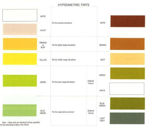
162 HYPSOMETRIC TINT 162
")
163 FOURTH SCHEDULE HYPSOMETRIC TINT GUIDE (Made under regulation 16) 163
164 164

165 The Civil Aviation (Aeronautical Charts) SCHEDULE 5: SHEET LAYOUT INDEX FOR THE WORLD SHEET LAYOUT INDEX FOR THE WORLD AERONAUTICAL CHART ICAO 1:
Overview ICAO Standards and Recommended Practices for Aerodrome Mapping Data reported to AIM
 Overview ICAO Standards and Recommended Practices for Aerodrome Mapping Data reported to AIM References ICAO SARPS Annex 14 Vol. I, 7 th Edition, July 2016 ICAO SARPS Annex 15, 15 th Edition, July 2016
INTERNATIONAL STANDARDS AND RECOMMENDED PRACTICES AERONAUTICAL CHARTS ANNEX 4 TO THE CONVENTION ON INTERNATIONAL CIVIL AVIATION
 COVER SHEET TO AMENDMENT 57 INTERNATIONAL STANDARDS AND RECOMMENDED PRACTICES AERONAUTICAL CHARTS ANNEX 4 TO THE CONVENTION ON INTERNATIONAL CIVIL AVIATION ELEVENTH EDITION JULY 2009 INTERNATIONAL CIVIL
Civil Aviation Requirements For Aeronautical Charts
 Civil Aviation Requirements For Aeronautical Charts CAR 4 AERONAUTICAL CHARTS First Edition January, 2009 Civil Aviation Authority of Nepal Amendments Amendments and Corrigenda to these " CIVIL AVIATION
Electronic Terrain and Obstacle Data
 International Civil Aviation Organization Electronic Terrain and Obstacle Data David Lewtas Chief, Aeronautical Information Unit (MET/AIM) 24 November 2010 ICAO CAR AIM Seminar Kingston, Jamaica 22-24
ADVISORY CIRCULAR AC-AD-005
 GHANA CIVIL AVIATION AUTHORITY ADVISORY CIRCULAR AC-AD-005 AERODROME QUALITY DATA SYSTEM GENERAL Ghana Civil Aviation Authority (GCAA) Advisory Circulars from Aerodrome Safety and Standards (ASAS) contain
Lecture Minimum safe flight altitude
 Lecture Minimum safe flight altitude Calculate of minimum safe flight altitude, safe flight altitude in approach zone, in circle zone (circle altitude), minimum safe flight altitude in aerodrome area,
USE OF RADAR IN THE APPROACH CONTROL SERVICE
 USE OF RADAR IN THE APPROACH CONTROL SERVICE 1. Introduction The indications presented on the ATS surveillance system named radar may be used to perform the aerodrome, approach and en-route control service:
Consideration will be given to other methods of compliance which may be presented to the Authority.
 Advisory Circular AC 139-10 Revision 1 Control of Obstacles 27 April 2007 General Civil Aviation Authority advisory circulars (AC) contain information about standards, practices and procedures that the
AERONAUTICAL SERVICES ADVISORY MEMORANDUM (ASAM) Focal Point: Gen
 Focal Point: Gen") Page 1 of 14 1 INTRODUCTION This guidance material has been prepared for use for the definition of protected surfaces in the vicinity of aerodromes. Survey information for an aerodrome is essential for
Page 1 of 14 1 INTRODUCTION This guidance material has been prepared for use for the definition of protected surfaces in the vicinity of aerodromes. Survey information for an aerodrome is essential for
THE CIVIL AVIATION ACT (No. 21 of 2013 THE CIVIL AVIATION (OPERATION OF AIRCRAFT) (AMENDMENT) REGULATIONS, 2015
 (AMENDMENT) REGULATIONS, 2015") LEGAL NOTICE. THE CIVIL AVIATION ACT (No. 21 of 2013 THE CIVIL AVIATION (OPERATION OF AIRCRAFT) (AMENDMENT) REGULATIONS, 2015 Citation GN. No. of 20 Citation 1. These Regulations may be cited as the Civil
LEGAL NOTICE. THE CIVIL AVIATION ACT (No. 21 of 2013 THE CIVIL AVIATION (OPERATION OF AIRCRAFT) (AMENDMENT) REGULATIONS, 2015 Citation GN. No. of 20 Citation 1. These Regulations may be cited as the Civil
TANZANIA CIVIL AVIATION AUTHORITY AIR NAVIGATION SERVICES INSPECTORATE. Title: CONSTRUCTION OF VISUAL AND INSTRUMENT FLIGHT PROCEDURES
 Page 1 of 8 1. PURPOSE 1.1. This Advisory Circular provides guidance to personnel involved in construction of instrument and visual flight procedures for publication in the Aeronautical Information Publication.
CHAPTER 5 SEPARATION METHODS AND MINIMA
 CHAPTER 5 SEPARATION METHODS AND MINIMA 5.1 Provision for the separation of controlled traffic 5.1.1 Vertical or horizontal separation shall be provided: a) between IFR flights in Class D and E airspaces
IRELAND SAFETY REGULATION DIVISION
 NOTICE TO AIR NAVIGATION SERVICE PROVIDERS IRELAND SAFETY REGULATION DIVISION NR S.016 ISSUE 1 DATE 03.03.10 IRISH AVIATION AUTHORITY AVIATION HOUSE HAWKINS STREET DUBLIN 2 Tel +353 1 6718655 Fax +353
Aeronautical Information Services Issue 1 30 May 2012
 United Kingdom Overseas Territories Aviation Circular OTAC 175-1 Aeronautical Information Services Issue 1 30 May 2012 GENERAL Effective: on issue Overseas Territories Aviation Circulars are issued to
MINIMUM FLIGHT ALTITUDES
 MINIMUM FLIGHT ALTITUDES 1. Introduction Minimum flight altitudes are created first to ensure safety, awareness and adequate radio navigation reception for aircraft flying at the same time in specific
AERONAUTICAL SERVICES ADVISORY MEMORANDUM (ASAM) Focal Point: Gen
 Focal Point: Gen") Page 1 of 6 1 INTRODUCTION Each route shall be assigned a designator that is unique for that aerodrome. The designator shall be defined in accordance with Annex 11, Appendix 3. In addition, the first 4
Page 1 of 6 1 INTRODUCTION Each route shall be assigned a designator that is unique for that aerodrome. The designator shall be defined in accordance with Annex 11, Appendix 3. In addition, the first 4
Manual of Radiotelephony
 Doc 9432 AN/925 Manual of Radiotelephony Approved by the Secretary General and published under his authority Fourth Edition - 2007 International Civil Aviation Organization AMENDMENTS The issue of amendments
Chapter 6. Nonradar. Section 1. General DISTANCE
 12/10/15 JO 7110.65W Chapter 6. Nonradar Section 1. General 6 1 1. DISTANCE Use mileage based (DME and/or ATD) procedures and minima only when direct pilot/controller communications are maintained. FIG
Chapter 6. Airports Authority of India Manual of Air Traffic Services Part 1
 Chapter 6 6.1 ESSENTIAL LOCAL TRAFFIC 6.1.1 Information on essential local traffic known to the controller shall be transmitted without delay to departing and arriving aircraft concerned. Note 1. Essential
distance and time to descend from a given level or altitude. LO Find the frequency and/or identifiers of radio-navigation aids from charts.
 Anne II to ED Decision 2016/008/R (1) For mass definitions, please refer to Chapter D. Syllabus 033 00 00 00 FLIGHT PLANNING AND MONITORING Aeroplane Helicopter / 033 01 00 00 FLIGHT PLANNING FOR VFR FLIGHTS
IFR SEPARATION WITHOUT RADAR
 1. Introduction IFR SEPARATION WITHOUT RADAR When flying IFR inside controlled airspace, air traffic controllers either providing a service to an aircraft under their control or to another controller s
JAA Administrative & Guidance Material Section Five: Licensing, Part Two: Procedures
 INTRODUCTION Preliminary general remark: 1 To fully appreciate and understand subject 033, the applicant will benefit from background knowledge in subjects 010, 020, 031, 032/034, 050, 060, 070 and 080.
Contents. Subpart A General 91.1 Purpose... 7
 Contents Rule objective... 3 Extent of consultation... 3 Summary of comments... 4 Examination of comments... 6 Insertion of Amendments... 6 Effective date of rule... 6 Availability of rules... 6 Part 91
AIR LAW AND ATC PROCEDURES
 1 The International Civil Aviation Organisation (ICAO) establishes: A standards and recommended international practices for contracting member states. B aeronautical standards adopted by all states. C
AERODROME OPERATING MINIMA
 Title: Determination of Aerodrome Operating Minima Page 1 of 8 AERODROME OPERATING MINIMA 1. PURPOSE 1.1 The purpose of this Advisory Circular is to provide methods to be adopted by operators in determining
GBAS ICAO Provisions. Presented by Sylvie GRAND-PERRET EUROCONTROL Navigation Unit
 GBAS ICAO Provisions Presented by Sylvie GRAND-PERRET EUROCONTROL Navigation Unit ICAO EUR GBAS Implementation Workshop Paris 18th March 2010 Applicable ICAO provisions ICAO Global provisions ANNEX 10
Overview ICAO Standards and Recommended Practices for Aerodrome Safeguarding
 Overview ICAO Standards and Recommended Practices for Aerodrome Safeguarding References The Convention on International Civil Aviation (Chicago Convention) ICAO SARPS Annex 14 Vol. I, 7 th Edition, July
ICAO Recommended Airport Signs, Runway And Taxiway Markings. COPYRIGHT JEPPESEN SANDERSON, INC., ALL RIGHTS RESERVED. Revision Date:
 ICAO Recommended Airport Signs, Runway And Taxiway Markings Revision Date: 20051230 MANDATORY INSTRUCTION SIGNS A mandatory instruction sign identifies a location beyond which an aircraft taxiing shall
 IFR 91.157 Must be instrument rated to fly special VFR at Night (civil twilight to civil twilight, sun 6 degrees below horizon) 91.159 Unless in a holding pattern of 2 minutes or less, VFR cruising altitude
AD 2. AERODROMES. For the ICAO location indicators used for Canadian aerodromes, refer to the following publications:
 AIP CANADA (ICAO) PART 3 AERODROMES (AD) AD 2. AERODROMES AD 2.1 Aerodrome Location Indicator and Name For the ICAO location indicators used for Canadian aerodromes, refer to the following publications:
GHANA CIVIL AVIATION (AIR NAVIGATION SERVICES) DIRECTIVES PART 15 AERONAUTICAL INFORMATION SERVICES
 DIRECTIVES PART 15 AERONAUTICAL INFORMATION SERVICES") GHANA CIVIL AVIATION (AIR NAVIGATION SERVICES) DIRECTIVES PART 15 AERONAUTICAL INFORMATION SERVICES TABLE OF CONTENTS TABLE OF CONTENTS... 2 15.1 GENERAL... 5 15.1.1 INTRODUCTION... 5 15.1.2 DEFINITIONS...
GHANA CIVIL AVIATION (AIR NAVIGATION SERVICES) DIRECTIVES PART 15 AERONAUTICAL INFORMATION SERVICES TABLE OF CONTENTS TABLE OF CONTENTS... 2 15.1 GENERAL... 5 15.1.1 INTRODUCTION... 5 15.1.2 DEFINITIONS...
Aerodrome Obstacle Survey Information Checks
 United Kingdom Overseas Territories Aviation Circular OTAC 139-20 Aerodrome Obstacle Survey Information Checks Issue 2.00 26 May 2017 Effective on issue GENERAL Overseas Territories Aviation Circulars
EXPLANATION OF TPP TERMS AND SYMBOLS
 U.S. TERMINAL PROCEDURES PUBLICATION 52 EXPLANATION OF TPP TERMS AND SYMBOLS The discussions and examples in this section will be based primarily on the IFR (Instrument Flight Rule) Terminal Procedures
AERONAUTICAL INFORMATION SERVICES TO AERONAUTICAL INFORMATION MANAGEMENT STUDY GROUP (AIS-AIMSG)
") AIS-AIMSG/5-IP/3 02/11/11 AERONAUTICAL INFORMATION SERVICES TO AERONAUTICAL INFORMATION MANAGEMENT STUDY GROUP (AIS-AIMSG) FIFTH MEETING Montréal, 7 to 11 November 2011 Agenda Item 9: Other Business Report
AIS-AIMSG/5-IP/3 02/11/11 AERONAUTICAL INFORMATION SERVICES TO AERONAUTICAL INFORMATION MANAGEMENT STUDY GROUP (AIS-AIMSG) FIFTH MEETING Montréal, 7 to 11 November 2011 Agenda Item 9: Other Business Report
CHAPTER 7 AEROPLANE COMMUNICATION AND NAVIGATION EQUIPMENT
 CHAP 7-1 CHAPTER 7 COMMUNICATION AND NAVIGATION EQUIPMENT 7.1 COMMUNICATION EQUIPMENT 7.1.1 An aeroplane shall be provided with radio communication equipment capable of: a) conducting two-way communication
ICAO Standards. Airfield Information Signs. ICAO Annex 14, 4th Edition Aerodrome Design and Operations
 ICAO Standards Airfield Information Signs ICAO Annex 14, 4th Edition Aerodrome Design and Operations Federal Aviation Administration U.S. Department of Transportation February 2004 ICAO Standards This
GOVERNMENT OF INDIA OFFICE OF DIRECTOR GENERAL OF CIVIL AVIATION
 GOVERNMENT OF INDIA OFFICE OF DIRECTOR GENERAL OF CIVIL AVIATION ANSS AC NO. 1 of 2017 31.07. 2017 Air Space and Air Navigation Services Standard ADVISORY CIRCULAR Subject: Procedures to follow in case
Safety and Airspace Regulation Group
 Safety and Airspace Regulation Group 24 August 2015 Policy Statement POLICY FOR POINT MERGE AND TROMBONE TRANSITION PROCEDURES 1 Introduction 1.1 The Point Merge transition procedure is an Area Navigation
Orientation Booklet The New Airline Chart Series
 Orientation Booklet The New Airline Chart Series Copyright 2007 Jeppesen. All rights reserved. Table of Contents Introduction...1 Approach Chart...2 Heading...2 Plan View...2 Profile View... Minimums...
SITE ELEVATION AMSL...Ground Elevation in feet AMSL STRUCTURE HEIGHT...Height Above Ground Level OVERALL HEIGHT AMSL...Total Overall Height AMSL
 ******************************************** * Federal Airways & Airspace * * Summary Report * ******************************************** File: User Assigned File Name Latitude: NAD83 Coordinate Longitude:
FIT FOR PURPOSE: A Guide to Using NAV CANADA Aeronautical Publications SECTION B PUBLICATION SPECIFIC FIT FOR PURPOSE INFORMATION
 FIT FOR : A Guide to Using NAV CANADA Aeronautical Publications SECTION B PUBLICATION SPECIFIC FIT FOR INFORMATION I TABLE OF CONTENTS SECTION A: GENERAL MATERIAL 2 SECTION B: PUBLICATION SPECIFIC FIT
ENR 1.7 ALTIMETER SETTING PROCEDURES
 AIP LEBANON ENR 1.7-1 11 APR 2008 ENR 1.7 ALTIMETER SETTING PROCEDURES 1. Introduction: 1.1 The procedures herein describe the method used in providing adequate vertical separation between aircraft and
Sample Regulations for Water Aerodromes
 Sample Regulations for Water Aerodromes First Edition (unedited version) March 2015 Notice to users: This document is an unedited version which is made available to the public for convenience. Its content
AERODROME LICENCE APPLICATION PROCESS
 0000180111 Page 2 Why is a Licence Required? An aerodrome licence is required for a site if it is intended to facilitate operations by commercial transport aircraft, other aerial work other than rotorcraft,
REGULATION No. 10/2011 ON APPROVAL OF FLIGHT PROCEDURES INCLUDING SID-s AND STAR-s. Article 1 Scope of Application
 Republika e Kosovës Republika Kosovo Republic of Kosovo Autoriteti i Aviacionit Civil i Kosovës Autoritet Civilnog Vazduhoplovstva Kosova Civil Aviation Authority of Kosovo Director General of Civil Aviation
AIR NAVIGATION ORDER
 CLEARANCE AREAS AND OBSTACLE LIMITATION SURFACES AT AIR NAVIGATION ORDER VERSION : 2.0 DATE OF IMPLEMENTATION : 15-02-2013 OFFICE OF PRIME INTEREST : AERODROME STANDARDS BRANCH. (Directorate of Airspace
SUBPART C Operator certification and supervision
 An AOC specifies the: SUBPART C Operator certification and supervision Appendix 1 to OPS 1.175 Contents and conditions of the Air Operator Certificate (a) Name and location (principal place of business)
CIVIL AVIATION AUTHORITY, PAKISTAN OPERATIONAL CONTROL SYSTEMS CONTENTS
 CIVIL AVIATION AUTHORITY, PAKISTAN Air Navigation Order No. : 91-0004 Date : 7 th April, 2010 Issue : Two OPERATIONAL CONTROL SYSTEMS CONTENTS SECTIONS 1. Authority 2. Purpose 3. Scope 4. Operational Control
ADVISORY CIRCULAR ON CALCULATION OF DECLARED DISTANCES
 Page 1 of 6 1. PURPOSE This Advisory circular (AC) provides guidance to operators to calculated declared distances at aerodrome for safe use of runway and promulgation of aeronautical data to the aeronautical
All-Weather Operations Training Programme
 GOVERNMENT OF INDIA CIVIL AVIATION DEPARTMENT DIRECTOR GENERAL OF CIVIL AVIATION OC NO 3 OF 2014 Date: OPERATIONS CIRCULAR Subject: All-Weather Operations Training Programme 1. INTRODUCTION In order to
1.2 An Approach Control Unit Shall Provide the following services: c) Alerting Service and assistance to organizations involved in SAR Actions;
 Alerting Service and assistance to organizations involved in SAR Actions;") Section 4 Chapter 1 Approach Control Services Approach Control Note: This section should be read in conjunction with Section 2 (General ATS), Section 6 (Separation Methods and Minima) and Section 7 (ATS
Section 4 Chapter 1 Approach Control Services Approach Control Note: This section should be read in conjunction with Section 2 (General ATS), Section 6 (Separation Methods and Minima) and Section 7 (ATS
Subject: Aeronautical Information Services
 GOVERNMENT OF INDIA OFFICE OF DIRECTOR GENERAL OF CIVIL AVIATION TECHNICAL CENTRE, OPP SAFDARJANG AIRPORT, NEW DELHI CIVIL AVIATION REQUIREMENTS SECTION 4, AERODROME STANDARDS & AIR TRAFFIC SERVICES SERIES
APPENDIX D FEDERAL AVIATION REGULATIONS, PART 77
 APPENDIX D FEDERAL AVIATION REGULATIONS, PART 77 Subparts A through C PART 77 - OBJECTS AFFECTING NAVIGABLE AIRSPACE Subpart A General 77.1 Scope. 77.2 Definition of terms. 77.3 Standards. 77.5 Kinds of
AREA NAVIGATION RNAV- MANAGEMENT
 1. Introduction AREA NAVIGATION RNAV- MANAGEMENT RNAV is an instrument-based navigation method that leads to fly from a fix (geographic point inside an airspace) to another fix directly. Contrary to conventional
CIVIL AVIATION ACT (Act No. 11 of 2011) CIVIL AVIATION (AERODROMES) REGULATIONS, 2012 (Published on 28th December, 2012) ARRANGEMENT OF REGULATIONS
 CIVIL AVIATION (AERODROMES) REGULATIONS, 2012 (Published on 28th December, 2012) ARRANGEMENT OF REGULATIONS") Supplement C Botswana Government Gazette dated 28th December, 2012 C.925 Statutory Instrument No. 101 of 2012 CIVIL AVIATION ACT (Act No. 11 of 2011) CIVIL AVIATION (AERODROMES) REGULATIONS, 2012 (Published
Supplement C Botswana Government Gazette dated 28th December, 2012 C.925 Statutory Instrument No. 101 of 2012 CIVIL AVIATION ACT (Act No. 11 of 2011) CIVIL AVIATION (AERODROMES) REGULATIONS, 2012 (Published
SULAYMANIYAH INTERNATIONAL AIRPORT MATS CHAPTER 11
 KURDISTAN REGIONAL GOVERNMENT SULAYMANIYAH INTERNATIONAL AIRPORT MATS CHAPTER 11 SEPARATION STANDARDS & APPLICATIONS International and Local Procedures ( First Edition ) April 2012 Ff Prepared By Fakhir.F.
Learning Objectives 7.3 Flight Performance and Planning Flight Planning & Flight Monitoring
 030 00 00 00 FLIGHT PERFORMANCE AND PLANNING 033 00 00 00 FLIGHT PLANNING AND FLIGHT MONITORING 033 01 00 00 FLIGHT PLANNING FOR VFR FLIGHTS Remark Using Training Route Manual VFR charts or CQB Annexes
NOISE ABATEMENT PROCEDURES
 1. Introduction NOISE ABATEMENT PROCEDURES Many airports today impose restrictions on aircraft movements. These include: Curfew time Maximum permitted noise levels Noise surcharges Engine run up restrictions
RULES OF TENNESSEE DEPARTMENT OF TRANSPORTATION AERONAUTICS DIVISION CHAPTER LICENSING AND REGISTRATION OF AIRPORTS TABLE OF CONTENTS
 RULES OF TENNESSEE DEPARTMENT OF TRANSPORTATION AERONAUTICS DIVISION CHAPTER 1680-1-2 LICENSING AND REGISTRATION OF AIRPORTS TABLE OF CONTENTS 1680-1-2-.01 Purpose 1680-1-2-.06 Repealed 1680-1-2-.02 Definitions
SECTION 6 - SEPARATION STANDARDS
 SECTION 6 - SEPARATION STANDARDS CHAPTER 1 - PROVISION OF STANDARD SEPARATION 1.1 Standard vertical or horizontal separation shall be provided between: a) All flights in Class A airspace. b) IFR flights
AD 2. AERODROMES VAKS AD 2.2 AERODROME GEOGRAPHICAL AND ADMINISTRATIVE DATA
 AD 2-1 AD 2. AERODROMES AD 2.1 AERODROME LOCATION INDICATOR AND NAME - KESHOD / DOMESTIC AD 2.2 AERODROME GEOGRAPHICAL AND ADMINISTRATIVE DATA 1 Aerodrome reference point coordinates and its site 2 Direction
Aeronautical Information Services
 GOVERNMENT OF INDIA OFFICE OF DIRECTOR GENERAL OF CIVIL AVIATION TECHNICAL CENTRE, OPP SAFDARJANG AIRPORT, NEW DELHI CIVIL AVIATION REQUIREMENTS SECTION 9 AIR SPACE AND AIR TRAFFIC MANAGEMENT SERIES 'I'
Gestão de Tráfego Aéreo 2015/2016 Exam Name Student ID Number. I (5.5/20, 0.5 each)
") Gestão de Tráfego Aéreo 2015/2016 Exam 2016.01.04 Name Student ID Number I (5.5/20, 0.5 each) What is each contracting state of ICAO required to provide? [ ] Modern radio navigation facilities for aeroplanes
Gestão de Tráfego Aéreo 2015/2016 Exam 2016.01.04 Name Student ID Number I (5.5/20, 0.5 each) What is each contracting state of ICAO required to provide? [ ] Modern radio navigation facilities for aeroplanes
ENR 1.1 GEN. RULES (Insert para 13 in ENR 1.1 of AIP India as follows)
") TEL: +91-11-24632950 Extn: 2219/2233 AFS: VIDDYXAX FAX: +91-11-24615508 Email: gmais@aai.aero INDIA AERONAUTICAL INFORMATION SERVICE AIRPORTS AUTHORITY OF INDIA RAJIV GANDHI BHAVAN SAFDARJUNG AIRPORT NEW
TEL: +91-11-24632950 Extn: 2219/2233 AFS: VIDDYXAX FAX: +91-11-24615508 Email: gmais@aai.aero INDIA AERONAUTICAL INFORMATION SERVICE AIRPORTS AUTHORITY OF INDIA RAJIV GANDHI BHAVAN SAFDARJUNG AIRPORT NEW
CLEARANCE INSTRUCTION READ BACK
 CLEARANCE INSTRUCTION READ BACK 1. Introduction An ATC clearance or an instruction constitutes authority for an aircraft to proceed only in so far as known air traffic is concerned and is based solely
Part 175.D & E Aeronautical Data Originators Data Product Specification: Vertical Obstructions
 Part 175.D & E Aeronautical Data Originators Data Product Specification: Vertical Obstructions ATS-DPS-0010 Version 2 Effective 22 December 2017 Prepared: Authorised: Sateesh Sathineni Aeronautical Data
ALTIMETER SETTING PROCEDURES
 AIP New Zealand ENR 1.7-1 ENR 1.7 ALTIMETER SETTING PROCEDURES 1 INTRODUCTION 1.1 General 1.1.1 The requirements for altimeter setting are detailed in CAR Part 91. The requirements are summarised in this
Aeronautical Information Services
 Aeronautical Information Services Division Manual AIS-OPS Aeronautical Information Services Operations Manual (Draft) Published by Aeronautical Information Services Division First Edition January, 2010
Data Catalogue. Subject Property Sub-Property Type Description Note Reference Accuracy Integrity Orig Type
 Data Catalogue Subject Property Sub-Property Type Description Note Reference Accuracy Integrity Orig Type Pub. Aerodrome / Heliport A defined area on land or water (including any buildings, installations
AIRSPACE STRUCTURE. In aeronautics, airspaces are the portion of the atmosphere controlled by a country above its territory.
 AIRSPACE STRUCTURE 1. Introduction In aeronautics, s are the portion of the atmosphere controlled by a country above its territory. There are two kinds of : Controlled is of defined dimensions within which
PBN Syllabus Helicopter. Learning Objective. phase Theoretical PBN concept. in ICAO Doc 9613)
") PBN Syllabus Helicopter Training Topic phase Theoretical PBN concept training (as described in ICAO Doc 9613) PBN principles PBN components PBN scope Navigation specifications RNAV and RNP Navigation functional
PBN Syllabus Helicopter Training Topic phase Theoretical PBN concept training (as described in ICAO Doc 9613) PBN principles PBN components PBN scope Navigation specifications RNAV and RNP Navigation functional
LOW VISIBILITY OPERATION
 1. Introduction LOW VISIBILITY OPERATION Low visibility procedures exist to support low visibility operations at aerodromes. Low visibility procedures (LVP) means procedures applied at an aerodrome for
Instrument Proficiency Check Flight Record
 Instrument Proficiency Check Flight Record Date: Flight Time: Sim. Inst. Time: Pilot Name: Aircraft Type: Aircraft Tail Number: Act. Inst. Time: Instructor Name: Holding Procedures Task Notes N/A Satisfactory
Consideration will be given to other methods of compliance which may be presented to the Authority.
 Advisory Circular AC 139-9 Notification of aerodrome data and information Revision 2 27 April 2007 General Civil Aviation Authority advisory circulars (AC) contain information about standards, practices
IFR SEPARATION USING RADAR
 IFR SEPARATION USING RADAR 1. Introduction When flying IFR inside controlled airspace, air traffic controllers either providing a service to an aircraft under their control or to another controller s traffic,
( I N S E R T A E R O D R O M E N A M E ) A E R O D R O M E M A N U A L AERODROME MANUAL. [Enter Name of Aerodrome]
![( I N S E R T A E R O D R O M E N A M E ) A E R O D R O M E M A N U A L AERODROME MANUAL. [Enter Name of Aerodrome]](/thumbs/73/68710390.jpg "( I N S E R T A E R O D R O M E N A M E ) A E R O D R O M E M A N U A L AERODROME MANUAL. [Enter Name of Aerodrome]") AERODROME MANUAL [Enter Name of Aerodrome] [Enter Date for current version] E.g. 11 TH January 2012 Page 1 FOREWORD The (insert aerodrome name) Aerodrome Manual has been prepared pursuant to the requirements
AERODROME MANUAL [Enter Name of Aerodrome] [Enter Date for current version] E.g. 11 TH January 2012 Page 1 FOREWORD The (insert aerodrome name) Aerodrome Manual has been prepared pursuant to the requirements
CFIT-Procedure Design Considerations. Use of VNAV on Conventional. Non-Precision Approach Procedures
 OCP-WG-WP 4.18 OBSTACLE CLEARANCE PANEL WORKING GROUP AS A WHOLE MEETING ST. PETERSBURG, RUSSIA 10-20 SEPTEMBER 1996 Agenda Item 4: PANS-OPS Implementation CFIT-Procedure Design Considerations Use of VNAV
SECTION 4 - APPROACH CONTROL PROCEDURES
 SECTION 4 - APPROACH CONTROL PROCEDURES CHAPTER 1 - PROVISION OF SERVICES 1.1 An approach control unit shall provide:- a) Approach control service. b) Flight Information service. c) Alerting service. RESPONSIBILITIES
HEAD-UP DISPLAY (HUD), EQUIVALENT DISPLAYS AND VISION SYSTEMS
, EQUIVALENT DISPLAYS AND VISION SYSTEMS") ATT 2.B-1 ATTACHMENT 2.B HEAD-UP DISPLAY (HUD), EQUIVALENT DISPLAYS AND VISION SYSTEMS Supplementary to 2.2.2.2, 2.4.15.1, 3.4.2.7 and 3.6.12 Introduction The material in this attachment provides guidance
ATT 2.B-1 ATTACHMENT 2.B HEAD-UP DISPLAY (HUD), EQUIVALENT DISPLAYS AND VISION SYSTEMS Supplementary to 2.2.2.2, 2.4.15.1, 3.4.2.7 and 3.6.12 Introduction The material in this attachment provides guidance
Sao Tome and Principe Civil Aviation Régulations
 INAC INSTITUTO NACIONAL DE AVIAÇÃO CIVIL Sao Tome and Principe Civil Aviation Régulations STPCAR - PART 15 AERONAUTICAL INFORMATION SERVICES LIST OF EFFECTIVE PAGES Pages Revision Date of Revision 15-1
AIS-AIMSG/12-SN/3 - Appendix A. New Annex 15. (Consolidated draft, 14 OCT 2015)
") AIS-AIMSG/12-SN/3 - Appendix A New Annex 15 (Consolidated draft, 14 OCT 2015) Contents CHAPTER 1. GENERAL 4 1.1 Definitions 4 1.2 Common reference systems for air navigation 10 1.2.1 Horizontal reference
AIS-AIMSG/12-SN/3 - Appendix A New Annex 15 (Consolidated draft, 14 OCT 2015) Contents CHAPTER 1. GENERAL 4 1.1 Definitions 4 1.2 Common reference systems for air navigation 10 1.2.1 Horizontal reference
IVAO Flight Operations Department Indonesia (ID) Division Procedures
 Division Procedures") IVAO Flight Operations Department Indonesia (ID) Division Procedures Revised April 12 rd, 2010 Please consult also the local application of common procedures on http://www.ivao.web.id 1. General 1.1 In
IVAO Flight Operations Department Indonesia (ID) Division Procedures Revised April 12 rd, 2010 Please consult also the local application of common procedures on http://www.ivao.web.id 1. General 1.1 In
AERONAUTICAL INFORMATION SERVICES-AERONAUTICAL INFORMATION MANAGEMENT STUDY GROUP (AIS-AIMSG)
") AIS-AIMSG/11-SN/6 20/04/2015 AERONAUTICAL INFORMATION SERVICES-AERONAUTICAL INFORMATION MANAGEMENT STUDY GROUP (AIS-AIMSG) Agenda Item 4: Information Distribution 4.1: AIP ELEVENTH MEETING Montreal, April
AIS-AIMSG/11-SN/6 20/04/2015 AERONAUTICAL INFORMATION SERVICES-AERONAUTICAL INFORMATION MANAGEMENT STUDY GROUP (AIS-AIMSG) Agenda Item 4: Information Distribution 4.1: AIP ELEVENTH MEETING Montreal, April
Appendix C AIRPORT LAYOUT PLANS
 Appendix C AIRPORT LAYOUT PLANS Appendix C AIRPORT LAYOUT PLANS Airport Master Plan Santa Barbara Airport As part of this Airport Master Plan, the Federal Aviation Administration (FAA) requires the development
PBN Syllabus Aeroplane. Learning Objective. phase Theoretical PBN concept. in ICAO Doc 9613)
") PBN Syllabus Aeroplane Training Topic phase Theoretical PBN concept training (as described in ICAO Doc 9613) PBN principles PBN components PBN scope Navigation specifications RNAV and RNP Navigation functional
PBN Syllabus Aeroplane Training Topic phase Theoretical PBN concept training (as described in ICAO Doc 9613) PBN principles PBN components PBN scope Navigation specifications RNAV and RNP Navigation functional
FLIGHT OPERATIONS PANEL (FLTOPSP)
") International Civil Aviation Organization FLTOPSP/1-WP/3 7/10/14 WORKING PAPER FLIGHT OPERATIONS PANEL (FLTOPSP) FIRST MEETING Montréal, 27 to 31 October 2014 Agenda Item 4: Active work programme items
International Civil Aviation Organization FLTOPSP/1-WP/3 7/10/14 WORKING PAPER FLIGHT OPERATIONS PANEL (FLTOPSP) FIRST MEETING Montréal, 27 to 31 October 2014 Agenda Item 4: Active work programme items
GCAA ADVISORY CIRCULAR
 GUYANA CIVIL AVIATION AUTHORITY 73 High Street Kingston Georgetown GUYANA TEL. NOs: (592) 225 6822, 225 0778, 227 8111 FAX: (592) 225 6800 E-mail: director-general@gcaa-gy.org GCAA ADVISORY CIRCULAR AERODROME
The aim of any instrument approach is to allow the aircraft to safely descend to a low altitude in order to become visual.
 INSTRUMENT APPROACH CHARTS "An instrument approach is just a series of straight lines joined by rate one turns" Ron Magrath The aim of any instrument approach is to allow the aircraft to safely descend
CAR ATS AIR TRAFFIC SERVICES
 CAR ATS AIR TRAFFIC SERVICES FOREWORD CONTENTS REVISION RECORD LIST of EFFECTIVE PAGES CAR ATS This Page Intentionally Left Blank CAR ATS FOREWORD 1. The Republic of San Marino Civil Aviation Authority,
European Aviation Safety Agency
 European Aviation Safety Agency RMG.0464 Requirements for air traffic services ICAO ANNEX 11 CHECKLIST based on ICAO ANNEX 11 Thirteenth Edition July 2001 incorporating all amendments up to Amendment No
Single Engine Instrument Training Record I PREFLIGHT PREPARATION WEATHER INFORMATION weather reports and forecasts. pilot and radar reports.
 Single Engine Instrument Training Record I PREFLIGHT PREPARATION WEATHER INFORMATION weather reports and forecasts. pilot and radar reports. surface analysis charts. radar summary charts. significant weather
SECURITY OVERSIGHT AGENCY June 2017 ALL WEATHER (CAT II, CAT III AND LOW VISIBILITY) OPERATIONS
 OPERATIONS") ADVISORY CIRCULAR CIVIL AVIATION SAFETY AND CAA:AC-OPS052 SECURITY OVERSIGHT AGENCY June 2017 1.0 PURPOSE ALL WEATHER (CAT II, CAT III AND LOW VISIBILITY) OPERATIONS This Order provides guidance to the
ADVISORY CIRCULAR CIVIL AVIATION SAFETY AND CAA:AC-OPS052 SECURITY OVERSIGHT AGENCY June 2017 1.0 PURPOSE ALL WEATHER (CAT II, CAT III AND LOW VISIBILITY) OPERATIONS This Order provides guidance to the
Challenges in Complex Procedure Design Validation
 Challenges in Complex Procedure Design Validation Frank Musmann, Aerodata AG ICAO Workshop Seminar Aug. 2016 Aerodata AG 1 Procedure Validation Any new or modified Instrument Flight Procedure is required
The following criteria shall be applied within the boundaries of the AO District:
 Sec. 419 (a) Purpose AIRPORT OVERLAY DISTRICT (AO) The purpose of the Airport Overlay District is to regulate and restrict the height of structures, objects, or natural growth, regulate the locations of
SPECIAL PROCEDURES FOR IN-FLIGHT CONTINGENCIES IN OCEANIC AIRSPACE OF SEYCHELLES FIR
 Phone: 248-4384186 AFS: FSIAYNYX FAX: 248-4384179 Email: sezais@scaa.sc REPUBLIC OF SEYCHELLES CIVIL AVIATION AUTHORITY AERONAUTICAL INFORMATION SERVICE P.O.BOX 181, VICTORIA SEYCHELLES AIP SUPPLEMENT
CHAPTER 5 AEROPLANE PERFORMANCE OPERATING LIMITATIONS
 CHAP 5-1 CHAPTER 5 PERFORMANCE OPERATING LIMITATIONS 5.1 GENERAL 5.1.1 Aeroplanes shall be operated in accordance with a comprehensive and detailed code of performance established by the Civil Aviation
2.1 Private Pilot Licence (Aeroplane/Microlight)
") GOVERNMENT OF INDIA OFFICE OF THE DIRECTOR GENERAL OF CIVIL AVIATION TECHNICAL CENTRE, OPP. SAFDURJUNG AIRPORT, NEW DELHI CIVIL AVIATION REQUIREMENTS SECTION 7 FLIGHT CREW STANDARDS TRAINING AND LICENSING
GOVERNMENT OF INDIA OFFICE OF THE DIRECTOR GENERAL OF CIVIL AVIATION TECHNICAL CENTRE, OPP. SAFDURJUNG AIRPORT, NEW DELHI CIVIL AVIATION REQUIREMENTS SECTION 7 FLIGHT CREW STANDARDS TRAINING AND LICENSING
Airport Obstruction Standards
 Airport Obstruction Standards Dr. Antonio Trani Department of Civil and Environmental Engineering Virginia Tech Outline of this Presentation Obstructions to navigation around airports Discussion of Federal
EFFECTIVE 0901Z 29 MARCH 2018 TO 0901Z 24 MAY 2018 AIP CANADA (ICAO) Part 3 Aerodromes (AD)
 Part 3 Aerodromes (AD)") EFFECTIVE 0901Z 29 MARCH 2018 TO 0901Z 24 MAY 2018 AIP CANADA (ICAO) Part 3 Aerodromes (AD) Published by in accordance with ICAO Annexes 4 and 15 of the Convention on International Civil Aviation 2018
EFFECTIVE 0901Z 29 MARCH 2018 TO 0901Z 24 MAY 2018 AIP CANADA (ICAO) Part 3 Aerodromes (AD) Published by in accordance with ICAO Annexes 4 and 15 of the Convention on International Civil Aviation 2018
Republic of Iraq Ministry of Transport Iraq Civil Aviation Authority REGULATIONS (12) CERTIFICATION OF AERODROMES
 CERTIFICATION OF AERODROMES") Republic of Iraq Ministry of Transport Iraq Civil Aviation Authority REGULATIONS (12) CERTIFICATION OF AERODROMES Introduction This document specifies the criteria applied by the Certification Authority
Republic of Iraq Ministry of Transport Iraq Civil Aviation Authority REGULATIONS (12) CERTIFICATION OF AERODROMES Introduction This document specifies the criteria applied by the Certification Authority