SECTION 9 SUPPLEMENTS
|
|
|
- Gerard Sparks
- 5 years ago
- Views:
Transcription
1 ROBINSON MODEL R44 SECTION 9 SUPPLEMENTS SECTION 9 SUPPLEMENTS OPTIONAL EQUIPMENT SUPPLEMENTS Information contained in the following supplements applies only when the related equipment is installed. CONTENTS Page Peak Beam Searchlight Fixed Floats Heated Pitot Police Version ENG Version Garmin GPSMAP Pop-Out Floats ADS-B Equipment Autopilot Optional Avionics NON-U.S. SUPPLEMENTS The following supplements contain additional information required by certain countries: Brazilian Supplement Canadian Supplement CIS Supplement EASA Supplement IAC AR Supplement Ukrainian Supplement FAA APPROVED: 7 MAY i
2 INTENTIONALLY BLANK
3
4
5
6
7
8
9
10
11
12
13
14
15
16
17
18
19
20
21
22
23
24
25
26
27
28
29
30
31
32
33
34
35
36
37
38
39
40
41
42
43
44
45
46

47 ROBINSON MODEL R44 SECTION 9 POP-OUT FLOATS SUPPLEMENT FAA APPROVED R44 PILOT S OPERATING HANDBOOK POP-OUT FLOATS SUPPLEMENT This supplement must be included in the FAA-approved Pilot s Operating Handbook when pop-out floats are installed. Information contained herein supplements or supersedes the basic manual only in those areas listed in this supplement. For limitations, procedures, and performance information not contained in this supplement, consult the basic Pilot s Operating Handbook. APPROVED BY: Manager, Flight Test Branch ANM-160L Federal Aviation Administration Los Angeles Aircraft Certification Office, Transport Airplane Directorate DATE: LOG OF REVISIONS Page No. Date Page No. Date * Dec Dec Dec Dec Dec Dec Dec * * * * * Manufacturer s data, not FAA approved. 18 Dec Dec Dec Dec Dec Dec Dec 2015 REVISIONS APPROVED BY: DATE: Manager, Flight Test Branch ANM-160L Federal Aviation Administration Los Angeles Aircraft Certification Office, Transport Airplane Directorate
48 ROBINSON MODEL R44 SECTION 9 POP-OUT FLOATS SUPPLEMENT SECTION 1: GENERAL INTRODUCTION This supplement contains the changes and additional data applicable when pop-out floats are installed. Pop-out floats are intended for safety during over-water flights. Intentional water landings for other than training purposes are not recommended. NOTE The pop-out floats are not certified for ditching. Some countries may prohibit certain over-water operations. REVISED: 18 DEC
49 ROBINSON MODEL R44 SECTION 9 POP-OUT FLOATS SUPPLEMENT SECTION 2: LIMITATIONS AIRSPEED LIMITS ADDITIONAL AIRSPEED LIMITS 100 KIAS maximum at power above MCP. With floats stowed, 100 KIAS maximum with any combination of cabin doors removed. 80 KIAS maximum for float inflation. 80 KIAS maximum with floats inflated. 115 KIAS maximum with float system armed (safety catch in READY position). FLIGHT AND MANEUVER LIMITATIONS Maximum altitude decrease with floats inflated is 4000 feet. CAUTION Altitude loss greater than 4000 feet may cause floats to lose shape and rigidity due to atmospheric pressure increase. Do not inflate floats above 4000 feet AGL. PLACARDS Near inflation lever: V ne WITH FLOATS INFLATED: 80 KIAS FAA APPROVED: 18 DEC
50 ROBINSON MODEL R44 SECTION 9 POP-OUT FLOATS SUPPLEMENT SECTION 3: EMERGENCY PROCEDURES POWER FAILURE GENERAL CAUTION Lowering collective rapidly or applying excessive forward cyclic while helicopter is moving forward on water can cause floats to submerge and helicopter to nose over. CAUTION Float inflation may take up to three seconds. Squeeze inflation lever early enough to allow full inflation before water contact. POWER FAILURE ABOVE 500 FEET AGL Autorotation to land: Same as in basic manual. Autorotation to water: 1. Lower collective immediately to maintain rotor RPM. 2. Reduce airspeed to below 80 KIAS. 3. Adjust collective to keep RPM between 97 and 108% or apply full down collective if light weight prevents attaining above 97%. 4. If altitude permits, maneuver into wind. 5. Inflate floats. CAUTION Do not inflate floats above 80 KIAS. Do not exceed 80 KIAS with floats inflated. 6. At about 40 feet AGL, begin cyclic flare. 7. At about 8 feet AGL, apply forward cyclic and raise collective just before touchdown. Touch down in slight nose high attitude with nose straight ahead. 8. Maintain cyclic in touchdown position and do not lower collective full down until forward motion has stopped. FAA APPROVED: 18 DEC
51 ROBINSON MODEL R44 SECTION 9 POP-OUT FLOATS SUPPLEMENT SECTION 3: EMERGENCY PROCEDURES (cont d) POWER FAILURE BETWEEN 8 FEET AND 500 FEET AGL Autorotation to land: Same as in basic manual. Autorotation to water: 1. Lower collective immediately to maintain rotor RPM. 2. Reduce airspeed to below 80 KIAS. 3. Adjust collective to keep RPM between 97 and 108% or apply full down collective if light weight prevents attaining above 97%. 4. If altitude permits, maneuver into wind. 5. Inflate floats. CAUTION Do not inflate floats above 80 KIAS. Do not exceed 80 KIAS with floats inflated. 6. Maintain airspeed until water is approached, then begin cyclic flare. 7. At about 8 feet AGL, apply forward cyclic and raise collective just before touchdown. Touch down in slight nose high attitude with nose straight ahead. 8. Maintain cyclic in touchdown position and do not lower collective full down until forward motion has stopped. FAA APPROVED: 18 DEC
52 ROBINSON MODEL R44 SECTION 9 POP-OUT FLOATS SUPPLEMENT SECTION 3: EMERGENCY PROCEDURES (cont d) POWER FAILURE BELOW 8 FEET AGL Over land: Same as in basic manual. Over water: 1. Apply right pedal as required to prevent yawing. 2. Inflate floats. 3. Allow rotorcraft to settle. 4. Raise collective just before touchdown. MAXIMUM GLIDE DISTANCE CONFIGURATION Same as in basic manual except airspeed 80 KIAS with floats inflated. EMERGENCY WATER LANDING POWER OFF See procedures for power failures in this supplement. EMERGENCY WATER LANDING POWER ON 1. Reduce airspeed to below 80 KIAS. 2. Inflate floats. CAUTION Do not inflate floats above 80 KIAS. Do not exceed 80 KIAS with floats inflated. 3. Make normal approach and landing to water. FAA APPROVED: 18 DEC
53 ROBINSON MODEL R44 SECTION 9 POP-OUT FLOATS SUPPLEMENT SECTION 4: NORMAL PROCEDURES DAILY OR PREFLIGHT CHECKS 15. Pop-Out Floats Float and float cover condition Check Hose and fitting condition Check Pressure cylinder Check pressure Safety pin at pressure cylinder..... Verify removed Inflation lever safety Ready or Locked as required CAUTION Avoid night flight over water beyond autorotation distance to land. Height above water may be difficult to judge during a water landing. NOTE When OAT is below -10 C, there may be insufficient charge in pressure cylinder for full inflation. FLOAT INFLATION The red inflation lever located under the pilot s collective is equipped with a safety catch to prevent inadvertent float inflation. Prior to overwater flight, place the safety catch in the READY position. With the safety catch in the READY position, floats may be inflated by squeezing inflation lever. Over land, safety catch should be reset to LOCKED position. CAUTION Observe 115 KIAS speed limitation when safety catch is in READY position. FAA APPROVED: 18 DEC
54 ROBINSON MODEL R44 SECTION 9 POP-OUT FLOATS SUPPLEMENT SECTION 4: NORMAL PROCEDURES (cont d) FLOAT INFLATION (cont d) CAUTION The pressure cylinder also has provisions for a safety pin at the valve on the cylinder neck. This safety pin is for use during maintenance and cylinder transport only and must be removed at all other times. NOTE Some flapping of float covers during flight with floats inflated is normal. To minimize wear, consider removing covers if an extended flight with inflated floats is required. FAA APPROVED: 18 DEC
55 ROBINSON MODEL R44 SECTION 9 POP-OUT FLOATS SUPPLEMENT SECTION 4: NORMAL PROCEDURES (cont d) OPERATION ON WATER Safe operation on water has been demonstrated in waves up to 1 foot (0.3 m) (trough to crest). Maximum recommended water taxi speed is 5 knots. Some application of collective is required. Since the helicopter sits very low on water, it is likely that water will leak into the cabin. Intentional water landings should be limited to training. For training, seal the removable belly panels and landing gear cross tube cover using aluminum foil tape or duct tape. Avoid salt water if possible. There may be limited tail rotor clearance to water, particularly at aft CG. Also, even small waves may cause enough rocking to dip the tail rotor in the water. If tail rotor contact with water is suspected, have tail rotor inspected prior to further flight. (If no noticeable change in vibration occurs after suspected water contact, helicopter may be repositioned to nearest convenient inspection site.) CAUTION If starting or stopping rotor on water, ensure area is clear as helicopter can rotate one or more complete turns while tail rotor RPM is low. FAA APPROVED: 18 DEC
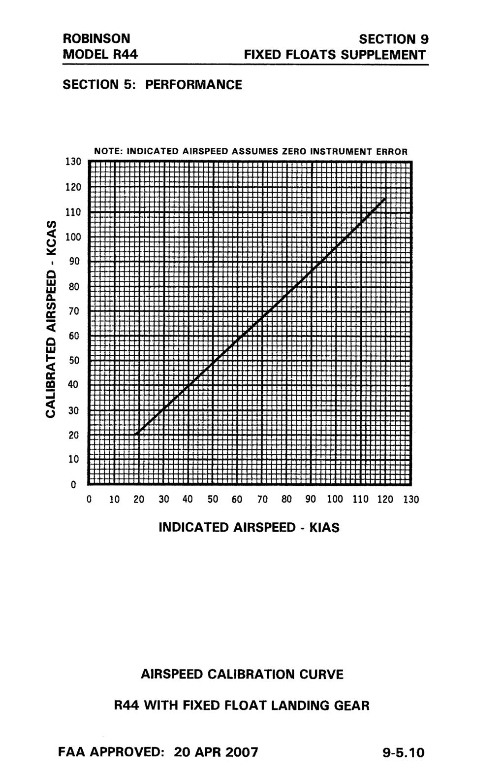
56 ROBINSON MODEL R44 SECTION 9 POP-OUT FLOATS SUPPLEMENT SECTION 4: NORMAL PROCEDURES (cont d) PRACTICE AUTOROTATION WITH GROUND CONTACT Same as in basic manual. Autorotations with floats stowed should only be performed to a smooth, hard surface to avoid damage to floats. Touch-down autorotations with floats inflated are not recommended due to the possibility of damage to floats. PRACTICE AUTOROTATION TO WATER Autorotation to water with floats inflated is same as practice autorotation with ground contact in basic manual except touch down in slight nose high attitude with nose straight ahead. Maintain cyclic in touchdown position and do not lower collective full down until forward motion has stopped. CAUTION Lowering collective rapidly or applying excessive forward cyclic while helicopter is moving forward on water can cause floats to submerge and helicopter to nose over. CAUTION There may be limited tail rotor clearance to water, particularly at aft CG. Applying excessive aft cyclic may cause tail rotor to contact water. SHUTDOWN PROCEDURE Add: Inflation lever safety LOCKED SECTION 5: PERFORMANCE No change. FAA APPROVED: 18 DEC
57 ROBINSON MODEL R44 SECTION 9 POP-OUT FLOATS SUPPLEMENT SECTION 6: WEIGHT AND BALANCE WEIGHT AND BALANCE RECORD Basic empty weight and CG with pop-out float landing gear and pressure cylinder installed are included in the Weight and Balance Summary provided with the helicopter. If pressure cylinder is removed, update Weight and Balance Record. A charged pressure cylinder weighs 11.4 lb. The longitudinal arm of the cylinder is 41.2 inches from datum and the lateral arm is -8.5 inches from datum. SECTION 7: SYSTEMS DESCRIPTION The pop-out float system consists of inflatable floats stowed in protective covers along the skid tubes, a pressure cylinder located in the compartment under the left front seat, flexible hoses from the cylinder to the floats, an inflation lever located on the pilot s collective, and an additional stabilizer installed at the base of the lower vertical stabilizer. The pressure cylinder is of aluminum construction reinforced with carbon filament windings and is charged with helium. Proper pressure is indicated on a placard on the cylinder, and pressure can be checked using the gage on the cylinder valve. A safety catch on the inflation lever can be set to prevent inadvertent actuation. With the safety catch in the READY position, floats are inflated by squeezing firmly on the inflation lever. (Approximately 20 lb force is required.) Float inflation time is approximately 2-3 seconds. With the safety catch in the LOCKED position, the inflation lever is locked out. To operate the safety catch, push spring-loaded knob with thumb while rotating U-shaped pin with forefinger as shown in figure. ISSUED: 18 DEC
58 ROBINSON MODEL R44 SECTION 9 POP-OUT FLOATS SUPPLEMENT ISSUED: 18 DEC
59 ROBINSON MODEL R44 SECTION 9 POP-OUT FLOATS SUPPLEMENT SECTION 7: SYSTEMS DESCRIPTION (cont d) The pop-out floats are approved for amphibious operation but are not certified for ditching. They are intended for enhanced safety during over-water flights. Intentional water landings for other than training purposes are not recommended. NOTE Floats maintain full pressure for at least 1 hour after inflation and typically maintain shape for several hours. Monitor float inflation state if helicopter is parked on water for an extended period. SECTION 8: HANDLING AND MAINTENANCE GROUND HANDLING With floats installed, special ground handling wheels (Robinson part number MT980-1 and MT980-2) are required. A safety pin is provided for installation at the pressure cylinder valve. This pin should be installed during maintenance and cylinder transport to prevent inadvertent pressure release. CAUTION With the safety pin installed, it is not possible to inflate the floats using the cockpit inflation lever. The safety pin is for use during maintenance and cylinder transport only and must be removed at all other times. FLOAT TUBES AND COVERS Immediately replace any damaged float tube cover to minimize chance of float damage. Inspect float tube condition after each inflation. Refer to R44 Maintenance Manual for periodic inspection, float repacking, and cylinder recharge instructions. ISSUED: 18 DEC
60 INTENTIONALLY BLANK ISSUED: 18 DEC
61 ROBINSON R44, R44 II, R44 CADET SECTION 9 ADS-B EQUIP. SUPPLEMENT FAA APPROVED R44, R44 II, R44 CADET PILOT S OPERATING HANDBOOK ADS-B EQUIPMENT SUPPLEMENT This supplement must be included in the FAA-approved Pilot s Operating Handbook when ADS-B equipment is installed. The information contained herein supplements or supersedes the basic manual only in those areas listed in this supplement. For limitations, procedures, and performance information not contained in this supplement, consult the basic Pilot s Operating Handbook. APPROVED BY: DATE: Manager, Flight Test Branch, ANM-160L Federal Aviation Administration, LAACO Transport Airplane Directorate LOG OF PAGES Page No. Date Page No. Date * * 27 JUN JUN JUN * 27 JUN JUN JUN 16 *Manufacturer s data, not FAA approved
62 ROBINSON R44, R44 II, R44 CADET SECTION 9 ADS-B EQUIP. SUPPLEMENT SECTION 1: GENERAL INTRODUCTION This supplement contains the changes and additional data applicable when Automatic Dependent Surveillance- Broadcast (ADS-B) equipment is installed. ADS-B is divided into two categories ADS-B Out and ADS-B In. ADS-B Out equipment transmits information to air traffic control to supplement radar/transponder information. The supplemental information allows optimization of flight plan routes and aircraft spacing. ADS-B Out equipment may be required for operation in certain airspace. The R44 ADS-B Out installation has been shown to meet the requirements of 14 CFR NOTE The R44 ADS-B Out system operates on frequency 1090 MHz. This frequency is also accepted for ADS-B Out equipment in most countries outside the United States. The ADS-B Out equipment consists of either a GPS receiver connected to the transponder or a transponder with built-in GPS. The transponder has ADS-B broadcast capability and broadcasts GPS position as well as additional preprogrammed information such as aircraft identification and type to air traffic control. ADS-B In equipment receives traffic information from other ADS-B equipped aircraft. ADS-B In equipment may also receive additional traffic information and weather information from ground stations. The additional traffic and weather information from ground stations is only available in the United States ISSUED: 27 JUN
63 ROBINSON R44, R44 II, R44 CADET SECTION 9 ADS-B EQUIP. SUPPLEMENT SECTION 1: GENERAL (cont d) INTRODUCTION (cont d) The ADS-B In equipment consists of a receiver (either installed under the left, front seat or built in to the transponder) and a suitable display. Refer to receiver and display manufactures documentation for operation of ADS-B In equipment. The R44 may be equipped with only ADS-B Out or with both ADS-B Out and ADS-B In. ISSUED: 27 JUN
64 ROBINSON R44, R44 II, R44 CADET SECTION 9 ADS-B EQUIP. SUPPLEMENT SECTION 2: LIMITATIONS PLACARDS On transponder when ADS-B Out equipment is installed: ADS-B OUT INSTALLED SECTION 3: EMERGENCY PROCEDURES No change. SECTION 4: NORMAL PROCEDURES ADS-B SYSTEM OPERATION ADS-B system operation is mostly automatic and requires little pilot action. The GPS (if separate from the transponder), transponder, and ADS-B receiver (if installed) must all be powered and in normal operating modes for proper system function. ADS-B OUT The R44 ADS-B Out system is a single point of entry system. Mode 3/A codes, IDENT commands, and emergency codes are set on the transponder and are automatically incorporated in ADS-B Out broadcasts. The transponder should transition to ALT mode after takeoff for proper ADS-B Out broadcasts. ADS-B Out broadcasts may be selected off by using menus associated with the transponder FUNC key. NOTE ADS-B Out may be required in certain airspace. Do not turn off ADS-B Out unless directed by air traffic control. Malfunctions in the ADS-B Out system are annunciated by various messages on the transponder and/or GPS screen (refer to manufacturers documentation). FAA APPROVED: 27 JUN
65 ROBINSON R44, R44 II, R44 CADET SECTION 9 ADS-B EQUIP. SUPPLEMENT SECTION 4: NORMAL PROCEDURES (cont d) ADS-B SYSTEM OPERATION (cont d) ADS-B IN The ADS-B In receiver is either mounted underneath the left, front seat or is built in to the transponder. The receiver is powered by the Transponder/ADS-B circuit breaker. ADS-B In data is sent from the receiver to a suitable display, often the primary GPS screen. The display may have dedicated traffic and weather views or may allow traffic and weather information to be overlaid on other data such as moving maps. Warnings such as traffic conflicts may also appear on the display. Refer to receiver and display manufacturers documentation. SECTION 5: PERFORMANCE No change. FAA APPROVED: 27 JUN
66 ROBINSON R44, R44 II, R44 CADET SECTION 9 ADS-B EQUIP. SUPPLEMENT SECTION 6: WEIGHT AND BALANCE No change. SECTION 7: SYSTEM DESCRIPTION ADS-B SYSTEM The ADS-B Out system consists of either a GPS receiver connected to the transponder or a transponder with built-in GPS. The transponder broadcasts the aircraft s position, identification, and certain other parameters to air traffic control. ADS-B data is broadcast via the Extended Squitter (ES) feature of the transponder on a frequency of 1090 MHz. Note that change of aircraft registration may require update of pre-programmed parameters by qualified maintenance personnel. Most of the data required for ADS-B broadcast such as aircraft type, ICAO address, and call sign are preprogrammed at installation. Flight-specific data such as Mode 3/A code and IDENT are entered using the transponder controls. The transponder uses these codes simultaneously for standard transponder as well as ADS-B broadcasts. There is no need to make a second code entry or to enter a code more than once. This is known as a single point of entry ADS-B system. The ADS-B In system consists of a receiver (either mounted under the left, front seat or built in to the transponder) and a suitable display. The receiver receives both approved US ADS-B frequencies (978 MHz and 1090 MHz). SECTION 8: No change. HANDLING, SERVICING AND MAINTENANCE ISSUED: 27 JUN
67 ROBINSON MODEL R44, R44 II SECTION 9 AUTOPILOT SUPPLEMENT FAA APPROVED R44 & R44 II PILOT S OPERATING HANDBOOK AUTOPILOT SUPPLEMENT This supplement must be included in the FAA-approved Pilot s Operating Handbook when the autopilot is installed. The information contained herein supplements or supersedes the basic manual only in those areas listed in this supplement. For limitations, procedures, and performance information not contained in this supplement, consult the basic Pilot s Operating Handbook. APPROVED BY: DATE: Manager, Flight Test Branch, ANM-160L Federal Aviation Administration, LAACO Transport Airplane Directorate LOG OF REVISIONS Page No. Date Page No. Date * 18 Dec Dec Dec Dec Dec * * * * * 18 Dec Dec Dec Dec Dec 15 * Manufacturer s data, not FAA approved. REVISIONS APPROVED BY: DATE: Manager, Flight Test Branch, ANM-160L Federal Aviation Administration, LAACO Transport Airplane Directorate
68 ROBINSON MODEL R44, R44 II SECTION 9 AUTOPILOT SUPPLEMENT SECTION 1: GENERAL INTRODUCTION This supplement contains the changes and additional data applicable when the autopilot is installed. CAUTION The autopilot is intended to enhance safety by reducing pilot workload. It is not a substitute for adequate pilot skill nor does it relieve the pilot of the responsibility to maintain adequate outside visual reference. The primary autopilot mode is Stability Augmentation System (SAS) mode which maintains a steady helicopter attitude by applying corrective inputs to the cyclic. The autopilot does not provide any collective or pedal inputs. Additional modes providing heading hold, altitude hold, and navigation functionality are also selectable. SECTION 2: LIMITATIONS FLIGHT AND MANEUVER LIMITATIONS Minimum altitude for use of autopilot ALT mode is 200 feet AGL. For practice instrument approaches, minimum altitude for use of autopilot VRT mode is 50 feet AGL. Pilot s hand must be on cyclic grip under the following conditions: During autopilot engagement or intentional disengagement At airspeeds less than 50 KIAS when less than 500 feet AGL FAA APPROVED: 18 DEC
69 ROBINSON MODEL R44, R44 II SECTION 9 AUTOPILOT SUPPLEMENT SECTION 3: EMERGENCY PROCEDURES AUTOPILOT DISENGAGEMENT OR FAILURE The autopilot is designed to automatically disengage if the system detects a fault. Disengagement is indicated by four beeps in the headset. If the autopilot does not automatically disengage, failure may be recognized by erratic cyclic control motion, abnormal cyclic stick forces, or deviations in pitch or roll. 1. Continue flight using manual control. If autopilot has not disengaged, manually disengage using cyclic AP OFF button or control panel SAS button. 2. If SAS annunciator on control panel is steady white, re-engagement may be attempted at pilot s discretion. NOTE The system automatically switches off all modes except SAS mode at airspeeds below 44 KIAS or above 130 KIAS, accompanied by a single beep. This is by design and not a system failure. SECTION 4: NORMAL PROCEDURES GENERAL Autopilot controls and operating modes are described in Section 7, Systems Description. NOTE Cyclic friction must be fully off for autopilot to work properly. Cyclic friction will degrade autopilot performance. FAA APPROVED: 18 DEC
70 ROBINSON MODEL R44, R44 II SECTION 9 AUTOPILOT SUPPLEMENT SECTION 4: NORMAL PROCEDURES STARTING ENGINE AND RUN-UP After Hydraulic system, add: Autopilot Check NOTE For autopilot check, wear headset and ensure cyclic friction is off. Engage SAS mode, and verify cyclic exhibits centering tendency and SAS annunciator on control panel turns green. Disengage. Verify 4 beeps in headset, cyclic reverts to normal hydraulic system feel, and SAS annunciator turns white. TAKEOFF PROCEDURE Autopilot SAS mode may be engaged as desired on the ground or at any time during the takeoff procedure. Retrim as necessary to eliminate undesirable cyclic forces. CRUISE Add: Engage autopilot modes as desired. In SAS mode, retrim as necessary to eliminate undesirable cyclic forces. CAUTION It is the pilot s responsibility to monitor flight controls, aircraft flightpath, traffic, and terrain even while the autopilot is engaged. Be prepared to take control if required. SECTION 5: PERFORMANCE No change. FAA APPROVED: 18 DEC
71 ROBINSON MODEL R44, R44 II SECTION 9 AUTOPILOT SUPPLEMENT SECTION 6: WEIGHT AND BALANCE No change. SECTION 7: SYSTEMS DESCRIPTION AUTOPILOT The autopilot system consists of two electric servomotors, a flight control computer, an autopilot control panel, and control buttons on the cyclic grip. One servomotor controls pitch and is installed in the control tunnel forward of the cyclic stick. The other servomotor controls roll and is installed under the pilot s seat. The servomotors are connected to the cyclic through electromagnetic clutches. The flight control computer is installed on the forward panel under the pilot s seat, and the autopilot control panel is installed in the avionics stack. In addition to the autopilot system components, an onboard attitude source such as an Attitude Heading Reference System (AHRS) is required. The primary autopilot mode is Stability Augmentation System (SAS) mode which maintains a steady helicopter attitude by applying corrective inputs to the cyclic. This is felt as a light cyclic centering force. The autopilot senses aircraft attitude using a combination of sensors in the flight control computer and the onboard attitude source. The computer then sends signals to the servomotors which are connected to the bottom of the cyclic in the control tunnel. Additional modes may be layered on top of SAS mode and are described below. REVISED: 18 DEC
72 ROBINSON MODEL R44, R44 II SECTION 9 AUTOPILOT SUPPLEMENT SECTION 7: SYSTEMS DESCRIPTION (cont d) AUTOPILOT (cont d) Heading Mode (HDG) maintains the heading selected by the heading bug on the directional gyro or Horizontal Situation Indicator (HSI) display. Aircraft can be steered using the heading bug. NOTE For large heading or course changes, the autopilot will use a maximum of 20 bank. Altitude Mode (ALT) maintains altitude at the time of engagement or of last TRIM button release. The target altitude is reset each time the TRIM button is pressed and released. NOTE The autopilot uses pitch attitude to maintain altitude or follow an approach glidepath. It does not have any control of power setting. The pilot must manage power with the collective to control speed and rate of climb or descent. Make small, smooth power changes to allow the system to adjust to new power settings. Navigation Mode (NAV) tracks the active GPS or VLOC course displayed on the Course Deviation Indicator (CDI). If no CDI is installed, NAV will only track the active GPS course displayed on the GPS. NAV may be armed prior to intercepting the active course. NAV annunciator is white when NAV is armed and turns green at course intercept. If HDG is active when NAV is armed, the autopilot will fly the selected heading until course intercept. If HDG is not active, the autopilot will select a 45 intercept angle. REVISED: 18 DEC
73 ROBINSON MODEL R44, R44 II SECTION 9 AUTOPILOT SUPPLEMENT SECTION 7: SYSTEMS DESCRIPTION (cont d) AUTOPILOT (cont d) Vertical Navigation Mode (VRT) tracks an ILS glideslope or GPS approach vertical guidance. Arm VRT (annunciator turns white when armed) prior to intercepting the glidepath. VRT annunciator will turn green at glidepath intercept NOTE Pushing the ALT button while VRT is armed or active will turn off VRT. VRT must be rearmed or re-engaged as desired. NOTE Reducing power to approach setting just prior to glidepath intercept is recommended. Backcourse Mode (BC) reverse CDI sensing for backcourse approaches. Course on HSI should be set so that tail of course pointer points toward runway (set to inbound front course). The control panel has a row of buttons to control autopilot modes and annunciators to indicate mode status. A dark annunciator indicates that a mode is off, a white annunciator indicates that a mode is armed or on standby, and a green annunciator indicates that a mode is active. When the avionics master is switched on, the autopilot performs a self-test and then enters SAS standby mode. All of the control panel indicators flash alternating white and green during the self-test. Four headset beeps occur at the beginning of the self-test as a check of the aural warning function. The SAS annunciator on the control panel turns steady white when the self-test is complete. NOTE Autopilot will not enter standby mode if attitude indicator is not functioning or indicated bank angle is greater than 6 degrees. REVISED: 18 DEC
74 ROBINSON MODEL R44, R44 II SECTION 9 AUTOPILOT SUPPLEMENT SECTION 7: SYSTEMS DESCRIPTION (cont d) AUTOPILOT (cont d) The autopilot SAS mode is engaged either by pressing the SAS button on the control panel or by pressing the TRIM button on the cyclic for more than 1.25 seconds. Additional modes are engaged by pressing the appropriate button on the control panel. The additional modes are disabled and will not engage at airspeeds below 44 KIAS or above 130 KIAS. To disengage any mode, push the appropriate button on the control panel. NOTE Disengaging SAS mode will also disengage all other modes. Modes may also be disengaged using the AP OFF button on the cyclic. If only SAS mode is engaged, push the AP OFF button once to disengage. If additional modes are engaged, push the AP OFF button once to disengage all modes except SAS and a second time to disengage SAS mode, or push and hold the AP OFF button to disengage all modes including SAS. NOTE SAS disengagement is always accompanied by four beeps in the headset. Safety monitors automatically disengage individual modes or the entire system if a fault is detected. Automatic disengagement of SAS mode (or the entire system) is indicated by four beeps in the headset. Automatic disengagement of any mode other than SAS is indicated by a single beep in the headset. There is no audio indication for intentional disengagement of modes other than SAS. REVISED: 18 DEC
75 ROBINSON MODEL R44, R44 II SECTION 9 AUTOPILOT SUPPLEMENT SECTION 7: SYSTEMS DESCRIPTION (cont d) AUTOPILOT (cont d) NOTE The system also automatically reverts to SAS mode at airspeeds below 44 KIAS or above 130 KIAS, accompanied by a single beep. The TRIM button is used to re-set the target attitude (to re-trim) while in SAS mode. Use a small amount of force to override the autopilot and then push and release the TRIM button at the new desired condition. If the force to override is objectionable, the TRIM button may be held down during maneuvers. The system will re-trim to the attitude at which the TRIM button is released. NOTE The system will not re-trim to more than 6 nose down, 11 nose up, or 10 of bank. If a re-trim is attempted outside these limits, the system will trim to the limiting value. NOTE When engaging SAS mode from standby, the autopilot uses the helicopter attitude at the time SAS mode is engaged as the target (trim) attitude. For large pitch and roll angles at the time of engagement, a target of 2 nose up pitch and 0 (level) roll is used. The autopilot is protected by a dedicated circuit breaker on the avionics bus (autopilot is not powered with the avionics master switch off). REMOVABLE FLIGHT CONTROLS On later aircraft, disconnect the electrical connector for the left-hand trim button located near the quick release pin before removing the left cyclic grip. Reconnect the connector when installing the left cyclic grip. REVISED: 18 DEC
76 ROBINSON MODEL R44, R44 II SECTION 9 AUTOPILOT SUPPLEMENT SECTION 8: HANDLING AND MAINTENANCE No change. SECTION 10: SAFETY TIPS The autopilot is intended to reduce pilot workload and enhance safety. It is important that pilots do not misuse this capability and allow their attention to be diverted from monitoring the helicopter attitude and looking for traffic and other obstacles. Autopilot disengagement requires immediate pilot attention. Pilots must always be prepared to take manual control. The autopilot is not certified for flight in Instrument Meteorological Conditions (IMC). Adhering to appropriate VFR weather minimums is essential for safety. If an inadvertent loss of outside visual reference occurs, the pilot must regain visual conditions as quickly as possible while avoiding abrupt, disorienting maneuvers. The following procedure is recommended: 1. If not already engaged, immediately engage autopilot SAS mode and allow autopilot to recover from unusual attitude if one has occurred. 2. Select a heading and altitude to ensure terrain and obstacle clearance. Turns and/or climbs may be required. Engage additional autopilot modes as desired for workload reduction. 3. While maintaining terrain and obstacle clearance, maneuver toward conditions of improved visibility. REVISED: 18 DEC
77 ROBINSON MODEL R44 FAA APPROVED R44 PILOT S OPERATING HANDBOOK OPTIONAL AVIONICS SUPPLEMENT This supplement must be included in the FAA-approved Pilot s Operating Handbook when certain factory-supplied optional avionics are installed. Information contained herein supplements or supersedes the basic manual only in those areas listed in this supplement. For limitations, procedures, and performance information not contained in this supplement, consult the basic Pilot s Operating Handbook. APPROVED BY: Manager, West Flight Test Section, AIR-716 Federal Aviation Administration Los Angeles, CA DATE: Page No * * LOG OF PAGES Date 7 May 18 7 May 18 7 May 18 7 May 18 Page No * * * * Manufacturer s data, not FAA approved. Date 7 May 18 7 May 18 7 May 18 Page
78 ROBINSON MODEL R44 SECTION 9 OPTIONAL AVIONICS SUPPLEMENT SECTION 1: GENERAL INTRODUCTION This supplement provides additional information for certain avionics options. A set of manufacturers instructions for all installed avionics is provided with each new helicopter. The following equipment is addressed in this supplement: Aspen Avionics EFD 1000H PFD and EFD 500H MFD Garmin G500H avionics system with touch screen display (GDU 700L TXi) NOTE For all Robinson Primary Flight Display (PFD)/ Multi Function Display (MFD) installations, the airspeed indicator, altimeter, compass, tachometer, and engine instruments are retained. Pilots should use the traditional instruments as primary unless fully familiar with the installed avionics. ISSUED: 7 MAY 2018 Page
79 ROBINSON MODEL R44 SECTION 9 OPTIONAL AVIONICS SUPPLEMENT SECTION 2: LIMITATIONS SECTION 3: EMERGENCY PROCEDURES SECTION 4: NORMAL PROCEDURES SECTION 5: PERFORMANCE SECTION 6: WEIGHT AND BALANCE SECTION 7: SYSTEMS DESCRIPTION No change. No change. No change. No change. No change. See below. SECTION 8: HANDLING AND MAINTENANCE No change. FAA APPROVED: 7 MAY 2018 Page
80 ROBINSON MODEL R44 SECTION 9 OPTIONAL AVIONICS SUPPLEMENT SECTION 7: SYSTEMS DESCRIPTION ASPEN EFD 1000H PFD AND EFD 500H MFD The Aspen Electronic Flight Display (EFD) 1000H is a Primary Flight Display (PFD) optimized for helicopter use. It is available in a Pilot (basic) version or Pro (with more advanced navigation features) version. The Aspen EFD 500H is a Multifunction Display (MFD) optimized for helicopter use. Robinson configurations are either a single EFD 1000H PFD or a dual installation with one EFD 1000H PFD and one EFD 500H MFD. A typical dual-installation instrument panel is illustrated on the following page. The manufacturer s documents for the EFD 1000H and EFD 500H are: Title Aspen Avionics Evolution Flight Display EFD 1000H PFD Pilot s Guide Aspen Avionics Evolution Flight Display EFD 1000H/500H MFD Pilot s Guide Document No NOTE A Robinson part no. D327-4 light filter may be used to reduce reflections in the windshield at night. The light filter is installed by clipping it to the front of the display. Filter use is at pilot discretion. ISSUED: 7 MAY 2018 Page
81 ROBINSON MODEL R44 SECTION 9 OPTIONAL AVIONICS SUPPLEMENT SECTION 7: SYSTEMS DESCRIPTION (cont d) 1. AIRSPEED INDICATOR 21. ROTOR BRAKE LIGHT 2. ENGINE AND ROTOR TACHS 22. IGNITION SWITCH 3. ALTIMETER 23. CLUTCH ACTUATOR SWITCH 4. MANIFOLD PRESSURE GAGE 24. CARBURETOR AIR TEMP 5. CLOCK 25. OUTSIDE AIR TEMP/VOLTMETER 6. MULTI-FUNCTION DISPLAY 26. PANEL LIGHTS DIMMER 7. PRIMARY FLIGHT DISPLAY 27. ENGINE INSTRUMENTS 8. CLUTCH ACTUATOR LIGHT 28. CABIN HEAT 9. M.R. GEARBOX TEMP LIGHT 29. NAVIGATION LIGHTS SWITCH 10. M.R. GEARBOX CHIP LIGHT 30. ANTI-COLLISION LIGHT SWITCH 11. CARBON MONOXIDE LIGHT 31. AVIONICS MASTER SWITCH 12. STARTER-ON LIGHT 32. ALTERNATOR SWITCH 13. T.R. GEARBOX CHIP LIGHT 33. BATTERY SWITCH 14. LOW FUEL LIGHT 34. CABIN AIR 15. LOW RPM LIGHT 35. AVIONICS STACK 16. ALT LOW VOLTAGE LIGHT 36. CYCLIC FRICTION 17. ENGINE FIRE LIGHT 37. CARBURETOR HEAT 18. OIL PRESSURE LIGHT 38. ELT SWITCH (OPT L) 19. GOVERNOR-OFF LIGHT 39. MIXTURE CONTROL 20. FULL THROTTLE LIGHT 40. PITOT HEAT SWITCH (OPT L) OPTIONAL INSTRUMENT PANEL WITH ASPEN EFD 1000H PFD and EFD 500H MFD (Exact panel configuration may vary with optional equipment and date of helicopter manufacture.) ISSUED: 7 MAY 2018 Page
82 ROBINSON MODEL R44 SECTION 9 OPTIONAL AVIONICS SUPPLEMENT SECTION 7: SYSTEMS DESCRIPTION (cont d) GARMIN G500H SYSTEM WITH GDU 700L TXi TOUCH SCREEN DISPLAY The Garmin GDU 700L TXi is a 7 inch diagonal PFD/ MFD designed for use with Garmin s G500H helicopter avionics system. The GDU 700L TXi uses a touch screen for pilot interface, with primary functions duplicated via knobs and buttons. Robinson s installation for the display is illustrated on the following page. The manufacturer s document for the G500H system with GDU 700L TXi display is: Title Garmin G500(H)/G600/G700 TXi Pilot s Guide Document No ISSUED: 7 MAY 2018 Page
83 ROBINSON MODEL R44 SECTION 9 OPTIONAL AVIONICS SUPPLEMENT SECTION 7: SYSTEMS DESCRIPTION (cont d) 1. AIRSPEED INDICATOR 21. IGNITION SWITCH 2. ENGINE AND ROTOR TACHS 22. CLUTCH ACTUATOR SWITCH 3. ALTIMETER 23. GPS NAVIGATOR 4. MANIFOLD PRESSURE GAGE 24. CARBURETOR AIR TEMP 5. CLOCK 25. OUTSIDE AIR TEMP/VOLTMETER 6. MULTI-FUNCTION DISPLAY 26. PANEL LIGHTS DIMMER 7. CLUTCH ACTUATOR LIGHT 27. ENGINE INSTRUMENTS 8. M.R. GEARBOX TEMP LIGHT 28. CABIN HEAT 9. M.R. GEARBOX CHIP LIGHT 29. NAVIGATION LIGHTS SWITCH 10. CARBON MONOXIDE LIGHT 30. ANTI-COLLISION LIGHT SWITCH 11. STARTER-ON LIGHT 31. AVIONICS MASTER SWITCH 12. T.R. GEARBOX CHIP LIGHT 32. ALTERNATOR SWITCH 13. LOW FUEL LIGHT 33. BATTERY SWITCH 14. LOW RPM LIGHT 34. CABIN AIR 15. ALT LOW VOLTAGE LIGHT 35. AVIONICS STACK 16. ENGINE FIRE LIGHT 36. CYCLIC FRICTION 17. OIL PRESSURE LIGHT 37. CARBURETOR HEAT 18. GOVERNOR-OFF LIGHT 38. ELT SWITCH (OPT L) 19. FULL THROTTLE LIGHT 39. MIXTURE CONTROL 20. ROTOR BRAKE LIGHT 40. PITOT HEAT SWITCH (OPT L) OPTIONAL INSTRUMENT PANEL WITH GARMIN G500H SYSTEM WITH GDU 700L TXi DISPLAY (Exact panel configuration may vary with optional equipment and date of helicopter manufacture.) ISSUED: 7 MAY 2018 Page
84 INTENTIONALLY BLANK
VFR Module 2. G1000 Transition VFR Module 2
 VFR Module 2 Course Content G1000 Proficiency Module 1 G1000 (VFR) Module 2 Autopilot (VFR) G1000 Flight Management Skills Information Management Personal preference (e.g., PFD/MFD configuration) Operation
AUTOMATION MANAGEMENT STANDARD OPERATING PROCEDURES
 MANAGEMENT STANDARD OPERATING PROCEDURES University of Dubuque Table of Contents Practical Test Standards..3 Levels of Automation..4 Limitations...7 Flight Director.. 8 Operating Procedures..9 Callouts
CESSNA 400 EQUIPPED WITH GARMIN G1000
 CESSNA 400 EQUIPPED WITH GARMIN G1000 After reading through the Information Manual, please complete this assignment. All answers can be found in the Information Manual in the section as noted in the right
Cessna 182R Initial Quiz Tail: N2365C Engine manufacturer, RPM. 7. How many fuel system drains are there?, where are they located?
 PILOT INSTRUCTOR_ DATE Cessna 182R Initial Quiz Tail: N2365C 04-17-08 Maximum normal category takeoff gross weight: lbs. Useful normal category load: lbs. Empty weight: lbs. What is the maximum landing
Pilot s Operating Handbook Supplement AS-04
 SECTION 9 Pilot s Operating Handbook Supplement GPS and Multifunctional Display FLYMAP L This AFM supplement is applicable and must be inserted into Section 9 of the Airplane Flight Manual when the FLYMAP
INSTRUCTIONS FOR USING THIS SAMPLE FLIGHT MANUAL SUPPLEMENT
 INSTRUCTIONS FOR USING THIS SAMPLE FLIGHT MANUAL SUPPLEMENT 1. For those installations not installed in accordance with GDL 82 Mooney M20 Series STC SA02573SE, a flight manual supplement may be created
Display Systems. 1. General. A. Multi-Function Display (MFD) B. Primary Flight Display (PFD)
 B. Primary Flight Display (PFD)") CIRRUS AIRPLANE MAINTENANCE MANUAL Display Systems CHAPTER 31-60: DISPLAY SYSTEMS GENERAL 31-60: DISPLAY SYSTEMS 1. General This section covers those systems and components which give visual display of
CIRRUS AIRPLANE MAINTENANCE MANUAL Display Systems CHAPTER 31-60: DISPLAY SYSTEMS GENERAL 31-60: DISPLAY SYSTEMS 1. General This section covers those systems and components which give visual display of
Advanced Transition Training
 Cirrus Aircraft Section 3 Syllabus Suite Advance Transition Advanced Transition Training The Advanced Transition Training course is designed to prepare a proficient instrument-rated pilot for an Instrument
GFC 700 AFCS Supplement
 GFC 700 AFCS Supplement GFC 700 AFCS Supplement Autopilot Basics Flight Director vs. Autopilot Controls Activating the System Modes Mode Awareness What the GFC 700 Does Not Control Other Training Resources
Introduction. Table of Contents. Chapter 1: Airplane General I. Airspeeds... 2
 Introduction This Pray Aviation Flight Training Manual (FTM) has been designed to provide the pilot with standardization procedures for safe and efficient training operations in the Beech Travelair. It
FLIGHT AND OPERATING MANUAL SUPPLEMENT FMS305902, REVISION 1 SEAPLANES WEST INC.
 FLIGHT AND OPERATING MANUAL SUPPLEMENT FMS305902, REVISION 1 AEROCET 3500/3500L FLOAT INSTALLATION ON CESSNA 182E THROUGH 182N AIRCRAFT AIRCRAFT MODEL: AIRCRAFT REGISTRATION: AIRCRAFT SERIAL NUMBER: TRANSPORT
Canadair Regional Jet 100/200 - Automatic Flight Control System
 1. INTRODUCTION The automatic flight control system (AFCS) provides integration of the autopilot and flight director systems. The AFCS system consists of two interlinked flight control computers (FCC 1
DA Aircraft Specifications and Limitations
 DA40-180 Aircraft Specifications and Limitations Pilot s Name: _ Instructor: Date: Answer all of the following questions as completely and thoroughly as possible in preparation for your checkout flight.
Navigation Systems. 1. The Chart Supplement provides a listing of available VOR receiver ground checkpoints and VOTs (VOR receiver test facilities).
.") Navigation Systems 3.1 DISTANCE MEASURING EQUIPMENT (DME) 1. DME displays slant range distance in nautical miles. 2. Ignore slant range error if the airplane is 1 NM or more from the ground facility for
Navigation Systems 3.1 DISTANCE MEASURING EQUIPMENT (DME) 1. DME displays slant range distance in nautical miles. 2. Ignore slant range error if the airplane is 1 NM or more from the ground facility for
Garmin GNC 420 GPS Navigator with VHF COM
 Cirrus Design Section 9 Pilot s Operating Handbook and FAA Approved Airplane Flight Manual Supplement for Garmin GNC 420 GPS Navigator with VHF COM When a GARMIN GNC 420 GPS Navigator with VHF COM is installed
This is the third of a series of Atlantic Sun Airways CAT A pilot procedures and checklists for our fleet. Use them with good judgment.
 This is the third of a series of Atlantic Sun Airways CAT A pilot procedures and checklists for our fleet. Use them with good judgment. Dimensions: Span 88 ft 9 in Length 89 ft 2 in Height 25 ft 1 in General
Garrecht TRX 1500 Traffic-Sensor
 SECTION 9 Pilot s Operating Handbook Supplement Garrecht TRX 1500 Traffic-Sensor This supplement is applicable and must be integrated into the Airplane Flight Manual if a Garrecht Traffic-Sensor is installed
BFC KNOWLEDGE TEST. 4. What are wing-tip vortices (wake turbulence)? With which aircraft are they the greatest? Describe proper avoidance?
? With which aircraft are they the greatest? Describe proper avoidance?") BFC KNOWLEDGE TEST PLEASE READ: The first half of the test incorporates general knowledge questions. The second half of the test is airplane specific. Only answer the questions for the airplane/ airplanes
BFC KNOWLEDGE TEST PLEASE READ: The first half of the test incorporates general knowledge questions. The second half of the test is airplane specific. Only answer the questions for the airplane/ airplanes
Valley Fliers 1402 Auburn Way North, #223 Auburn WA 98002
 Valley Fliers 1402 Auburn Way North, #223 Auburn WA 98002 Instructor: Check Out Date: Phase 1: Pre-Flight Name: Certificate Number: Certificate Type: Ratings: Total Flight Time: Last 90 Days: Club check
Instrument Proficiency Check Flight Record
 Instrument Proficiency Check Flight Record Date: Flight Time: Sim. Inst. Time: Pilot Name: Aircraft Type: Aircraft Tail Number: Act. Inst. Time: Instructor Name: Holding Procedures Task Notes N/A Satisfactory
CHAPTER 2 AIRCRAFT INFORMATION SUMMARY TABLE OF CONTENTS
 CHAPTER 2 AIRCRAFT INFORMATION SUMMARY TABLE OF CONTENTS General...2 Kinds of Operations...2 Structural and weight limitations...2 Maneuvering limitations...3 Flight load factor limitations...3 Power plant
INVESTIGATION REPORT. Incident to ATR registered F-GVZG on 11 September 2011 at Marseille
 INVESTIGATION REPORT www.bea.aero (1) Except where otherwise indicated, the times in this report are in Universal Time Coordinated (UTC). (2) Pilot Flying (3) Pilot Monitoring (4) MultiFunction Computer
BRIDGEWATER STATE UNIVERSITY PIPER SENECA PA
 PREFLIGHT CHECKLIST PA-34-200 COCKPIT AND CABIN MAINTENANCE STATUS... VERIFIED / CLEARED HOBBS / TACH METERS... RECORDED POH / AIRCRAFT DOCUMENTS... CHECKED PARKING BRAKE... ON FLIGHT CONTROLS (RELEASE
PRESOLO WRITTEN EXAM
 PRESOLO WRITTEN EXAM Date of Exam STUDENT INFORMATION Student Name Student Pilot Certificate Number FLIGHT INSTRUCTOR INFORMATION Instructor Instructor Certificate Number 1 INTRODUCTION Student Actions:
Advisory Circular (AC)
") Advisory Circular (AC) Flight Test Considerations For The Approval Of The Design Of Aircraft Modifications File No. 5009-6-513 AC No. 513-003 RDIMS No. 528350-V3 Issue No. 01 Issuing Branch Aircraft Certification
Advisory Circular (AC) Flight Test Considerations For The Approval Of The Design Of Aircraft Modifications File No. 5009-6-513 AC No. 513-003 RDIMS No. 528350-V3 Issue No. 01 Issuing Branch Aircraft Certification
N7579P (PA24-250) Checklist
 Checklist") Before Starting Engine Preflight inspection complete Seats, belts, harnesses adjusted & locked Landing gear selector DOWN Landing gear emergency handle FORWARD Fuel selector fullest main tank All avionics
Before Starting Engine Preflight inspection complete Seats, belts, harnesses adjusted & locked Landing gear selector DOWN Landing gear emergency handle FORWARD Fuel selector fullest main tank All avionics
SECTION 2 LIMITATIONS
 SECTION 2 LIMITATIONS TABLE OF CONTENTS Introduction... 3 Airspeed Limitations... 4 Airspeed Indicator Markings... 4 Powerplant Limitations... 5 Operations:... 5 Oil Limitation:... 5 Cylinder Head Temperature
CESSNA 172SP Part I. 2) The fuel selector may be in which of the following positions for landing? a) left b) right c) both d) all of the above
 The fuel selector may be in which of the following positions for landing? a) left b) right c) both d) all of the above") 1) What is the total usable fuel capacity? a) 56 gal b) 53 gal c) 56 gal d) 28 gal CESSNA 172SP Part I 2) The fuel selector may be in which of the following positions for landing? a) left b) right c) both
1) What is the total usable fuel capacity? a) 56 gal b) 53 gal c) 56 gal d) 28 gal CESSNA 172SP Part I 2) The fuel selector may be in which of the following positions for landing? a) left b) right c) both
F1 Rocket. Recurrent Training Program
 F1 Rocket Recurrent Training Program Version 1.0, June, 2007 F1 Rocket Recurrent Training Course Course Objective: The purpose of this course is to ensure pilots are properly trained, current and proficient
Garmin 500 Checkout. Addendum to Aircraft Checkout Form
 Addendum to Aircraft Checkout Form System The G500 system consists of the following units: GDU 620 - Primary Flight Display (PDF) & Multi-Function Display (MFD) o PFD shows primary flight information on
Date Student Name Instructor Aircraft Make and Model Time in Aircraft Initial score corrected to AHRS: ADC: TIS: Terrain: TRK: DTK: VNAV:
 Date Student Name Instructor Aircraft Make and Model Time in Aircraft Initial score corrected to 1. Define the following equipment terms: AHRS: ADC: TIS: Terrain: 2. Define the following navigation terms:
Cirrus Transition Training
 Cirrus Aircraft Syllabus Suite Section 2 Transition Cirrus Transition Training Cirrus Transition Training Requirements Flight Time Ground X-C Legs Landings Course Minimums 6 hrs NA 7 15 Course Averages
SR22T Pilot s Operating Handbook (POH) Temporary Change
 Temporary Change") Cirrus Design TPOH POH Temporary Change Pilot s Operating Handbook (POH) Temporary Change Information in this Temporary Change adds to, supersedes, or deletes information in the basic Pilot s Operating
Cirrus Design TPOH POH Temporary Change Pilot s Operating Handbook (POH) Temporary Change Information in this Temporary Change adds to, supersedes, or deletes information in the basic Pilot s Operating
ECLIPSE 500. Aircraft Overview. Do Not Use For Flight
 ECLIPSE 500 Aircraft Overview Do Not Use For Flight 1. Aircraft Overview 1.1 General The Eclipse 500 is a twin-turbofan aircraft powered by two Pratt & Whitney Canada PW610F-A engines. It is a five- to
Intentionally left blank
 Supplement D42L AFM Intentionally left blank Page 9-S4-2 Supplement D42L AFM Intentionally left blank Page 9-S4-4 D42L AFM Supplement LIST OF EFFECTIVE PAGES Chapter Page Date 0 DOT-approved 9-S4-1 24-May-11
SIMULATOR IN-FLIGHT COCKPIT SETUP
 I2103 Starting Position: Overhead KNSE WORKSHEET Altitude: 12,000 Heading: 360 SIMULATOR IN-FLIGHT COCKPIT SETUP Speed: 200 KIAS Special Syllabus Requirements Proceed direct to homefield using any available
Lesson Plan Introduction
 Lesson Plan Introduction The following flight training program has been designed with consideration for the student's comfort level. The advancement is dependent upon the student's ability. The following
DA-20-C1 Eclipse Private Pilot Flight Training Tips
 William R. Baumheuter FAA Designated Pilot Examiner 618-215-5151 Here are some tips to help assist you in the demonstration of knowledge and skills related to Takeoffs and Landings to the FAA Designated
Single Engine Instrument Training Record I PREFLIGHT PREPARATION WEATHER INFORMATION weather reports and forecasts. pilot and radar reports.
 Single Engine Instrument Training Record I PREFLIGHT PREPARATION WEATHER INFORMATION weather reports and forecasts. pilot and radar reports. surface analysis charts. radar summary charts. significant weather
ILS APPROACH WITH B737/A320
 ILS APPROACH WITH B737/A320 1. Introduction This documentation will present an example of Instrument landing system (ILS) approach performed with Boeing 737. This documentation will give some tips also
Autopilots. The most important thing we build is trust. Understanding their role in cockpit workload, safety and convenience
 Autopilots Understanding their role in cockpit workload, safety and convenience The most important thing we build is trust SINGLE AXIS AUTOPILOTS Control roll with a variety of models designed to fit virtually
Robin DR400/140 G-BAGR. Check-list
 Pre-flight check Check aircraft docs, weather, NOTAMs and Air Pilot Complete flight planning Check loading within limits Sign authorisation sheet Robin DR400/140 G-BAGR Check-list Cockpit preparations
CHAPTER AUTOMATIC FLIGHT CONTROL SYSTEM LIST OF ILLUSTRATIONS
 Vol. 1 03--00--1 AUTOMATIC FLIGHT CONTROL YTEM Table of Contents REV 3, May 03/05 CHAPTER 3 --- AUTOMATIC FLIGHT CONTROL YTEM Page TABLE OF CONTENT 03-00 Table of Contents 03--00--1 INTRODUCTION 03-10
601 XL SLSA FLIGHT TEST AUTHORIZATION THIS AIRCRAFT IS RELEASED FOR FLIGHT TEST
 601 XL SLSA FLIGHT TEST AUTHORIZATION Page 1 of 7 This approval document is not valid unless all Signatories have signed. Quality Assurance Declaration A search for Advisory Directives or Service Bulletins
SUPPLEMENT S04. Transport Canada Approved Flight Manual Supplement For GARMIN G500 PRIMARY FLIGHT AND MULTIFUNCTION DISPLAY SYSTEM
 Transport Canada Approved Flight Manual Supplement For This supplemental manual is applicable to Garmin G500 Primary Flight and Multifunction Display System equipped airplanes. This Supplement must be
CHECK FLIGHT CERTIFICATE
 CHECK FLIGHT CERTIFICATE Single/Twin Seat, Piston-Engined Light Gyroplanes CFS 301 Iss 4 Date: Crew: Observer: Registration: Performance Climb #1 Airfield: Average Weight Average Altitude lbs/kg ft Start
GAR-AERO WHEEL ADAPTERS & TIRES
 FOUND FBA-2C2 SUPPLEMENT M400-S03 Transport Canada Approved Flight Manual Supplement For GAR-AERO WHEEL ADAPTERS & This supplemental manual is applicable to Gar-Aero Wheel Adapters & 8.50-10 tires equipped
CESSNA SKYMASTER 337
 CABIN HEAT CONTROLS The heater controls are located on the lower section of the righthand side of the instrument panel. Access can be gained via the throttle/pedestal panel view. To operate the heater
FNPT II MEP IFR STANDARD OPERATIONAL PROCEDURES
 FNPT II MEP IFR STANDARD OPERATIONAL PROCEDURES Prepared by: Cpt. Tihamer Gyurkovits Version: FNPT II SOP 2.2 Last updated: 15/11/2017 Notes: -These SOP s and lists were developed for FNPT II training
REMOS GX Aircraft Check-out Sheet
 REMOS GX Aircraft Check-out Sheet Name Last: First: Certificate # Certificates Held Total Flight Time Hours Flown Last 90 days Medical Exp: Ratings: On Type On Type 90 days: Note: All available aircraft
Safety Syllabus. VFR into IMC
 VFR into IMC A syllabus designed to help protect pilots against GA's most fatal type of weather-related accident: VFR into IMC. Recommended for use by flight instructors and schools. 2017 421 Aviation
TRANSPORT CANADA MMEL SUPPLEMENT PIPER AIRCRAFT PA-31, PA , 325, 350 MASTER MINIMUM EQUIPMENT LIST
 MMEL SUPPLEMENT TO PIPER AIRCRAFT MASTER MINIMUM EQUIPMENT LIST Walter Istchenko Chief, Flight Test National Aircraft Certification for Minister of Transport Jan. 06, 2015 Revision: 02 INTENTIONALLY LEFT
General Characteristics
 This is the second of a series of Atlantic Sun Airways CAT C pilot procedures and checklists for our fleet. Use them with good judgment. Note, the start procedures may vary from FS9 Panel to Panel. However
For the purposes of this guidance material the following definitions are used:
 AMC1 FCL.710 - Guidance on differences training The following should be used as guidance when conducting differences training on types or variants within single pilot class or type ratings. Difference
BFR WRITTEN TEST B - For IFR Pilots
 (61 Questions) (Review and study of the FARs noted in parentheses right after the question number is encouraged. This is an open book test!) 1. (91.3) Who is responsible for determining that the altimeter
SUPPLEMENT S06. Transport Canada Approved Flight Manual Supplement For GARMIN 400W/500W SERIES GPS WASS NAVIGATION SYSTEM
 Transport Canada Approved Flight Manual Supplement For This supplemental manual is applicable to Garmin 400W/500W Series GPS WASS Navigation System equipped airplanes. This Supplement must be attached
Indiana State University Aerospace Technology
 Standard Operating Procedures Indiana State University Aerospace Technology Beechcraft King Air 200/B200 Standard Operating Procedures Indiana State University strongly supports the premise that the disciplined
ONE-ENGINE INOPERATIVE FLIGHT
 ONE-ENGINE INOPERATIVE FLIGHT 1. Introduction When an engine fails in flight in a turbojet, there are many things the pilots need to be aware of to fly the airplane safely and get it on the ground. This
Commercial Pilot Practical Test Briefing
 Commercial Pilot Practical Test Briefing 1. What certificates and documents must you have on board the aircraft prior to flight? 2. Locate the following inspections, as appropriate, in the airframe and
FLIGHT REVIEW February 1, 2018
 SUNRISE AVIATION FLIGHT REVIEW February 1, 2018 This form can be downloaded from the web: http://www.sunriseaviation.com/flightreview.pdf GENERAL FAR 61.56 has mandated minimum time requirements for Flight
Cover...0. Page #...0 TOC Index.0. Inside Back Cover..0. Outside Back Cover 0
 Pg Chg Cover...0 Page #......0 TOC-1...0 1.0 2.0 3.0 4.0 5.0 6.0 7.0 8. 0 9.0 10..0 11.. 0 12.. 0 13.. 0 14.. 0 15..0 Index.0 Inside Back Cover..0 Outside Back Cover 0 AXP340 Mode S Transponder with ADS-B
Pre-Solo Written Exam
 Pre-Solo Written Exam Introduction 14 CFR Part 61.87(b) requires student pilots to demonstrate aeronautical knowledge by completing a knowledge test prior to soloing an aircraft. The test must address
SERVICE BULLETIN. The airplanes that follow that are equipped with the Garmin G1000 Nav III Avionics Option and the WAAS installed with SB
 TITLE NAVIGATION - GARMIN G1000 ADS-B OUT INSTALLATION EFFECTIVITY The airplanes that follow that are equipped with the Garmin G1000 Nav III Avionics Option and the factory installed Wide Area Augmentation
This is the fifth of a series of Atlantic Sun Airways CAT B pilot procedures and checklists for our fleet. Use them with good judgment.
 This is the fifth of a series of Atlantic Sun Airways CAT B pilot procedures and checklists for our fleet. Use them with good judgment. Dimensions: Wing Span: 111 ft 3 in Length: 111 ft 0 in Height: 38
UH1H HP Modification and Upgrade Program
 UH1H HP Modification and Upgrade Program The UH-1H has served the United States military for many years, setting the performance standards for all helicopters. Since the start of production, over 10,000
COURSE OUTLINE PAGE: S-1 G1000 ORIENTATION AND CHECKOUT
 TRAINING COURSE OUTLINE PAGE: S-1 Outline and Course Materials G1000 Student Package A. Introduction 1. Course Objective: To acquire the necessary knowledge of and flight proficiency in a Cessna 172/182
Santa Monica Flyers. Pre-Solo Knowledge Test. Aircraft Type to be flown solo:
 Santa Monica Flyers Pre-Solo Knowledge Test Name: Date: Aircraft Type to be flown solo: Answer the following questions in the space provided using the FARs, AIM, Charts, the AFM/POH for the airplane to
NATIONAL PILOT LICENCING
 APPENDIX R62.16 NATIONAL PILOT LICENCE LIGHT SPORT AEROPLANE PRACTICAL TRAINING 1. Aim of training course The aim of the course is to train a candidate to the level of proficiency required for the issue
GENERAL REVIEW & PREFLIGHT TEST
 GENERAL REVIEW & PREFLIGHT TEST GUIDE TO MARKING The following logical sequence of steps is provided to assist instructors in the marking process when conducting preflight evaluations for Private and Commercial
Standard Training Procedures Remos GX
 Standard Training Procedures Remos GX Dear Pilot The following guide is intended to standardize most of the maneuvers you will encounter during your flight training. By no means is this document intended
Visualized Flight Maneuvers Handbook For Low Wing Aircraft
 Visualized Flight Maneuvers Handbook For Low Wing Aircraft Fourth Edition For Instructors and Students Visualized Flight Maneuvers Handbook For Low Wing Aircraft Fourth Edition For Instructors and Students
NATIONAL PILOT LICENCING
 APPENDIX R62.01 NATIONAL PILOT LICENCE CONVENTIONALLY CONTROLLED MICROLIGHTS PRACTICAL TRAINING 1. Aim of training course The aim of the course is to train a candidate to the level of proficiency required
March 2016 Safety Meeting
 March 2016 Safety Meeting AC 61 98C Subject: Currency Requirements and Guidance for the Flight Review and Instrument Proficiency Check Date: 11/20/15 AC No: 61-98C Initiated by: AFS-800 Supercedes: AC
Aim. To gain an understanding of the basic avionics functions featured in the C172 and other aircraft with similar avionic fit outs
 Avionics Basics Aim To gain an understanding of the basic avionics functions featured in the C172 and other aircraft with similar avionic fit outs 2 Avionics Basics VHF Radios Many modern aircraft feature
IATA Air Carrier Self Audit Checklist Analysis Questionnaire
 IATA Air Carrier Self Audit Checklist Analysis Questionnaire Purpose Runway Excursion Prevention Air Carrier Self Audit Checklist The Flight Safety Foundation (FSF) Reducing the Risk of Runway Excursions
1973 Cessna Skymaster 337 Instrumentation
 1973 Cessna Skymaster 337 Instrumentation The Cessna Skymaster 337 is a centerline thrust twin engine aircraft. In my research it seemed that no two had the same instrumentation. The aircraft instrumentation
ATP CTP CRJ-200 FSTD 1 Briefing Guide
 The objective is to demonstrate and allow the student to experience the high level concepts of larger, faster, and more complex transport category airplanes. Since the student is not being trained how
S YLLABUS SUITE Ö Ö0),/4Ö%$)4)/.
,/4Ö%$)4)/.") SYLLABUS SUITE SR20, SR22, SR22T Copyright 2018 - All Rights Reserved Cirrus Design Corporation 4515 Taylor Circle Revision 1: Jan 2018 P/N 23020-002 List of Effective Pages List of Effective Pages Use
SYLLABUS SUITE SR20, SR22, SR22T Copyright 2018 - All Rights Reserved Cirrus Design Corporation 4515 Taylor Circle Revision 1: Jan 2018 P/N 23020-002 List of Effective Pages List of Effective Pages Use
Alpha Systems AOA Classic & Ultra CALIBRATION PROCEDURES
 Alpha Systems AOA Calibration Overview The calibration of the Alpha Systems AOA has 3 simple steps 1.) (On the Ground) Zero calibration 2.) (In-flight) Optimum Alpha Angle (OAA) calibration 3.) (In-flight)
All-Weather Operations Training Programme
 GOVERNMENT OF INDIA CIVIL AVIATION DEPARTMENT DIRECTOR GENERAL OF CIVIL AVIATION OC NO 3 OF 2014 Date: OPERATIONS CIRCULAR Subject: All-Weather Operations Training Programme 1. INTRODUCTION In order to
del Airbus en el mundo de la
 Ing Ivan Ramirez Centro de ensayos de Airbus en Toulouse-Francia Automatización del Airbus en el mundo de la aviación Fly by wire aircraft Page 2 Contents Fly by wire principles Flight Handling Page 3
KEY FEATURES IN SHORT
 KA C90/B200/350 KA C90/B200/350 It is the fixed base simulator of commercial turboprop multi-crew aircraft. The simulator meets all the requirements determined for EASA CS-FSTD(A) FNPTII +MCC level. The
EFIS-D10A DYNON S BEST-SELLING. Specifications STC APPROVED FOR TYPE CERTIFICATED AIRCRAFT NOW NOW
 DYNON S BEST-SELLING EFIS-D10A NOW ACTUAL SIZE EFIS-D10A NOW Specifications WEIGHT EFIS-D10A: 1lb 7.4oz GPS-251 for EFIS-D10A: 7.4 oz Backup Battery: 6.4 oz EDC-D10A Remote Magnetometer 3.6 oz (optional):
Flight Evaluation Schedule For GPS IFR Approval Primary Means Enroute, Terminal and Non-Precision Approach
 Flight Evaluation Schedule For GPS IFR Approval Primary Means Enroute, Terminal and Non-Precision Approach Aircraft Description: Model ZK- Operator GPS Description: Manufacturer Model Serial Number TSO-C129
Pilot's Operating Handbook Supplement AS-09
 SECTION 9 Pilot's Operating Handbook Supplement GARMIN GTN 650 COM/NAV/GPS This supplement is applicable and must be inserted into Section 9 of the Pilot's Operating Handbook when the GARMIN GTN 650 system
Diamond Star DA40 Pre-Solo Written Exam
 Diamond Star DA40 Pre-Solo Written Exam Name: Date: Answer the following questions in the space provided, using the POH, Aircraft Checklist, FARs, AIM, and A/FD. If referencing any of these documents,
Section 7 Supplements. Miodel 400A SUPPLEMENTS
 Miodel 400A SUPPLEMENTS Section 7 Supplements NOTE When a new airplane is delivered from the factory, the handbook delivered with it contains either an STC (Supplement Type Certificate) Supplement or a
Aspen Flying Club E. Control Tower Rd, Unit K-16 Englewood, CO Tel: AmericanFlightSchools.com PRE-SOLO WRITTEN TEST
 Aspen Flying Club 13000 E. Control Tower Rd, Unit K-16 Englewood, CO 80112 Tel: 303-799-6794 AmericanFlightSchools.com PRE-SOLO WRITTEN TEST Student Pilot: (Print Name) Referring Instructor: (Print Name)
HARD. Preventing. Nosegear Touchdowns
 Preventing HARD Nosegear Touchdowns In recent years, there has been an increase in the incidence of significant structural damage to commercial airplanes from hard nosegear touchdowns. In most cases, the
MODEL: ELITE AATD RC-1
 ADVANCED AVIATION TRAINING DEVICE APPROVAL QUALIFICATION GUIDE FOR AZURE COMPUTING, INC (d.b.a. ELITE Simulation Solutions). ELITE ATD SYSTEMS MODEL: ELITE AATD RC-1 The purpose of this guide is to provide
REPORT SERIOUS INCIDENT
 www.bea.aero REPORT SERIOUS INCIDENT Momentary Loss of Control of the Flight Path during a Go-around (1) Unless otherwise specified, the times in this report are expressed in Universal Time Coordinated
HXr - Instrument Approach Option Manual Supplement
 GRT Avionics, Inc HXr - Instrument Approach Option Manual Supplement Revision: Initial Release 20-July-2018 GRT Avionics, Inc 1 07/20/18 Initial Release Revision Date Change Description Initial 20-07-2018
CESSNA SECTION 5 PERFORMANCE
 CESSNA SECTION 5 TABLE OF CONTENTS Page Introduction............................................5-3 Use of Performance Charts................................5-3 Sample Problem........................................5-4
Copyright 2016 GARMIN Ltd. or its subsidiaries All Rights Reserved
 Copyright 2016 GARMIN Ltd. or its subsidiaries All Rights Reserved Except as expressly provided herein, no part of this manual may be reproduced, copied, transmitted, disseminated, downloaded or stored
11/20/15 AC 61-98C Appendix 2 APPENDIX 2. SAMPLE AIRPLANE PILOT S PROFICIENCY PRACTICE PLAN. Flight Rules (VFR) Flight Profile Every 4-6 Weeks:
 Flight Profile Every 4-6 Weeks:") Appendix 2 APPENDIX 2. SAMPLE AIRPLANE PILOT S PROFICIENCY PRACTICE PLAN Pilot s Name: Date: Flight Rules (VFR) Flight Profile Every 4-6 Weeks: Preflight (include 3-P Risk Management Process (RMP) (Perceive
Appendix 2 APPENDIX 2. SAMPLE AIRPLANE PILOT S PROFICIENCY PRACTICE PLAN Pilot s Name: Date: Flight Rules (VFR) Flight Profile Every 4-6 Weeks: Preflight (include 3-P Risk Management Process (RMP) (Perceive
Launch and Recovery Procedures and Flight Maneuvers
 CJJfJA'J!Jf. 7J Launch and Recovery Procedures and Flight Maneuvers This chapter discusses glider launch and takeoff procedures, traffic patterns, landing and recovery procedures, and flight maneuvers.
MetroAir Virtual Airlines
 MetroAir Virtual Airlines NAVIGATION BASICS V 1.0 NOT FOR REAL WORLD AVIATION GETTING STARTED 2 P a g e Having a good understanding of navigation is critical when you fly online the VATSIM network. ATC
aerofly FS 2: Rodeo s Tutorial My second ILS approach
 You did follow the tutorial My first ILS approach. We will use quite the same flight for the next step. This time let s try a full automatic ILS approach. aerofly FS 2: Rodeo s Tutorial My second ILS approach
PRE-SOLO WRITTEN EXAM. Student Name:
 PRE-SOLO WRITTEN EXAM Student Name: Date: Instructor Name: INTRODUCTION As specified in FAR 61.87, you must demonstrate satisfactory knowledge of appropriate portions of FAR Parts 61 and 91 to an authorized
MINIMUM EQUIPMENT LIST REGISTRATION : N12345 S/N: BL-100
 REGISTRATION : S/N: BL-100 S/N: BL-100 ADDRESS CITY, ST ZIP PHONE CONTENTS PAGE Cover...- Contents Page... i List of Effective Pages...vii Log/Record Of Revisions...ix Definitions... x Preamble...xiv System