AIRFIELDFAMILIARIZATION 14CFRPART
|
|
|
- Garey Goodwin
- 5 years ago
- Views:
Transcription


1 CHICAGO O HAREINTERNATIONALAIRPORT ADVANCED AIRFIELDFAMILIARIZATION MANUAL 14CFRPART PREPAREDBY CITYOFCHICAGO DEPARTMENTOFAVIATION AIRFIELDOPERATIONS Revision /01
2 TABLE OF CONTENTS Summary of Changes... 6 Introduction... 9 CDA Address... 9 Airfield Operations Phone Numbers... 9 O Hare Communication Center Phone Numbers... 9 Phonetic Alphabet Facilities Familiarization ARFF (Rescue Stations) Gates Cargo Facilities Airfield Markings Runway Markings Marking Color Runway Designators Runway Use Information Runway Lengths and Widths Airport Reference Point Runway Centerline Marking Runway Aiming Point Marking Runway Touchdown Zone Markers Runway Side Stripe Marking Runway Shoulder Marking Runway Threshold Marking Relocated Threshold Marking Runway Displaced Threshold Marking
3 Demarcation Bar Chevrons Closed Runways and Taxiways Taxiway Markings General Non-Movement Area Boundary Marking Taxiway Centerline Marking Enhanced Taxiway Centerline Marking Taxiway Edge Markings Geographic Position Markings Taxiway Shoulder Markings Surface Painted Taxiway Direction Signs Surface Painted Taxiway Location Signs Runway Holding Position Markings Surface Painted Runway Holding Position Sign ILS Holding Position Marking Taxiway/Taxiway Intersection Intermediate Holding Position Roadway Markings Roadways Runway Safety Area Signs Taxiway Object Free Area Pavement Markings For B747-8 & A Airfield Signs Runway and Taxiway Guidance Signs General Information on Taxiway Designations Taxiway/Runway Intersection Runway/Runway Intersection
4 Instrument Landing System Critical Areas No Entry Areas Runway Approach Areas Cat II/III Operations Areas Runway Safety Area Holding Position Signs Directional Sign Location Signs Taxiway Location Sign Runway Location Sign Runway Approach Boundary Sign ILS Critical Area/POFZ Boundary and Cat II/III Operations Sign Runway Distance Remaining Sign Taxiway End Marker Destination Signs Information Signs Airfield Lighting Runway Edge Lights Touchdown Zone Lighting Runway Centerline Lighting Threshold/Runway End Lights Taxiway Centerline Lights Taxiway Lead-on/Lead-off Lights Land and Hold Short Lights (LAHSO) Taxiway Edge Lights Runway Guard Lights Stop Bars
5 Obstruction Lights Wind Cones Airport Rotating Beacon Runway Status Lights Runway Entrance Lights Takeoff Hold Lights Runway Status Lights Vehicle Procedures ATCT Light Gun Signals...49 FAA Navigational Aids Approach Lighting System (ALS) FAA Threshold Lights Precision Approach Path Indicators (Papi s) Instrument Landing System (ILS) Localizer Glideslope DVOR/DME DME Low-Level Windshear Alert System (LLWAS) Air Traffic Control Radio Phraseology ATCT Radio Communication Procedures Effective Communication Advanced Driver Safety Alert ORD AOA Safety Alert Operation of Ground Vehicles Runways Movement Area
6 Operations Near Aircraft Aircraft Repositioning Noise Abatement Runway Closures Advisory Lessons Learned Things Change Airport Sign and Marking Quick Reference Guide
7 Summary of Changes Revision /01 Revision /01 Revision /01 1. All graphics pertaining to nomenclature moved to supplement packet. 2. Content Revision MANDATORY INSTRUCTION SIGNS 3. Content Addition NON-MOVEMENT AREA BOUNDARY MARKING 1. Content Revision TAXIWAY SHOULDER MARKINGS Picture Update 1. Content Revision Rescue 2 & Rescue 4 locations following taxiway changes Revision /01 1. Content Revision Removal of any reference to RWY 15/33 6
8 INTENTIONALLY LEFT BLANK 7
9 INTENTIONALLY LEFT BLANK 8
10 INTRODUCTION This Manual was developed by the City of Chicago, Department of Aviation, Airport Airfield Operations Section (AAO). Its purpose is to implement training requirements mandated by 14 CFR , and to review important safety information relating to personnel who operate vehicles, equipment, and taxi aircraft in the movement area - runways, taxiways, and surrounding surfaces. This will enable you to understand the hazards and the controls created for your protection and for the safety of others at O Hare International Airport. It is the responsibility of each person who works in or around the movement area to study and understand this information. O HARE INTERNATIONAL AIRPORT CHICAGO DEPARTMENT OF AVIATION W. ZEMKE ROAD P.O. BOX CHICAGO, ILLINOIS AIRFIELD OPERATIONS CITY ATRIUM P O HARE COMMUNICATIONS CENTER EMERGENCIES NON-EMERGENCIES
11 PHONETIC ALPHABET Character Telephony Pronunciation Character Telephony Pronunciation A Alfa (AL-FAH) N November (NO-VEM-BER) B Bravo (BRAH-VOH) O Oscar (OSS-CAH) C Charlie (CHAR-LEE) P Papa (PAH-PAH) D Delta (DELL-TA) Q Quebec (KEH-BECK) E Echo (ECK-OH) R Romeo (ROW-ME-OH) F Foxtrot (FOKS-TROT) S Sierra (SEE-AIR-RAH) G Golf (GOLF) T Tango (TANG-GO) H Hotel (HOH-TEL) U Uniform (YOU-NEE-FORM) I India (IN-DEE-AH) V Victor (VIK-TAH) J Juliett (JEW-LEE-ETT) W Whiskey (WIS-KEY) K Kilo (KEY-LOH) X X-ray (ECKS-RAY) L Lima (LEE-MAH) Y Yankee (YANG-KEY) M Mike (MIKE) Z Zulu (ZOO-LOO) Character Telephony Pronunciation Character Telephony Pronunciation 1 One (WUN) 6 Six (SIX) 2 Two (TOO) 7 Seven (SEV-EN) 3 Three (TREE) 8 Eight (AIT) 4 Four (FOW-ER) 9 Nine (NIN-ER) 5 Five (FIFE) 0 Zero (ZEE-RO) * NOTE * When referencing a RUNWAY DESIGNATION - numbers are spoken in single digits between 0 and 9. When combining two number characters to say a runway you would speak a single digit, followed by a single digit. For example, Runway 10L would be spoken Runway One-Zero Left, NOT Runway Ten Left. 10
12 FACILITIES FAMILIARIZATION Concentrations of buildings on the airport consist of the core or Domestic Terminal Complex, International Terminal Complex, the Hangar Alley to the north, the cargo area to the Southwest and Southeast, the Airport Maintenance Complex (AMC) to the Southeast and the Northeast Ramp to the Northeast. The airport is also divided into landside operations and airside operations. The landside portion includes all terminal areas, access roads and the Kennedy (I-190) Expressway to Mannheim Road. The security checkpoints referred to as Guard posts provide access to the airside portion, where all air traffic movements take place. AIRCRAFT RESCUE AND FIRE FIGHTING STATIONS Chicago O Hare International Airport has four (4) Aircraft Rescue and Fire Fighting (ARFF) or rescue stations strategically located on airport property, three stations airside and one landside. O Hare is ARFF index E. 1. Rescue 1 is located on the south side of the airfield just Northwest of TWY S1 2. Rescue 2 is located on the North side of the airfield at the intersection of TWY YY and TWY C2 3. Rescue 3 (District 3 headquarters) is located landside, in the terminal core area off of the recirculation route just past Terminal 3 4. Rescue 4 is located on the North side of the airfield at the intersection of TWY C and TWY C PAD GATES In this section the trainee will be exposed to the various ramp areas on the airfield, including all gates at various concourses, and their number system as an identification method to locate a certain gate. There are a total of 188 gate positions at O Hare International Airport (ORD) which include all four (4) airline passenger terminals. 11
13 12
14 13
15 14
16 15
17 CARGO FACILITIES Northeast Cargo is located South of the Runway 22R APCH. The buildings include: AGI, Swissport, TAS Southwest Cargo is located South of Runway 10C-28C at Taxiway BB. FedEx is the only cargo carrier at this location. South Central Cargo is located South of Runway 10C-28C, East end of Taxiway Q and South end of Taxiway DD. United Cargo Building is the only cargo carrier at this location leasing space to AeroUnion, British Airways, CargoLux, Cathay Pacific, Justice, Kalitta Air, Southeast Cargo is located West of Taxiways S-1, S-2. The buildings include: Air France Cargo, American Airlines Cargo, Delta Cargo, Federal Express (second facility), KLM Cargo, Lufthansa Cargo, Nippon Cargo, and United Parcel Service. Chicago O Hare Express Center: The newest facility is located directly south of the AMC Building at the corner of Mannheim and Irving Park Road. The buildings to date include: Aer Lingus, Burlington Air Freight, Air Canada, Japan Airlines, British Airways, Cathay Pacific, Alliance, Korean Air, Challenge, Varig, Fin Air, Virgin Atlantic, Turkish Airlines, Lot Polish, Iberia, Eva, Midwest Express, Harjin, Saudi Arabian Airlines, Air New Zealand, Air Jordan, Shanghai Airlines Cargo, Singapore Airlines Cargo, China Southern, Air General, Polar Air Cargo, Swissport 16

18 17
 are yellow in color.")
19 MARKING COLOR RUNWAY MARKINGS All runway markings are white in color and outlined in black. ***** EXCEPTION TO THE RULE ***** Runway intersection hold short markings, taxiways lead in / lead out lines that extend onto the runway, and runway shoulder markings (chevrons) are yellow in color. RUNWAY DESIGNATORS - They are white in color and consist of a single digit number or two numbers and may be supplemented with a letter - The runway landing designator marking identifies a runway end located near the runway threshold. Types of single, dual parallel, and triple parallel runway designators: 1) A single-digit runway landing designation number is never preceded by a zero. 2) The designator number is the whole number nearest the one-tenth of the magnetic azimuth along the runway centerline when viewed from the direction of approach. For example, where the magnetic azimuth along the runway centerline is 273 degrees, the runway designator marking would be 27. L indicates a LEFT designation C indicates a CENTER designation R indicates a RIGHT designation 3) Two parallel runways having a magnetic azimuth of degrees the runways would be designated 27L, 27R. 4) Five parallel runways having a magnetic azimuth of degrees the runways would be designated 27L, 27R, 28L, 28C, 28R or 28L, 28R, 27L, 27C, 27R. 5) Six parallel runways having a magnetic azimuth of degrees the runways would be designated 9L, 9C, 9R, 10L, 10C, 10R. ***THE 5 EAST/WEST PARALLELS*** RUNWAYS ON THE NORTH AIRFIELD: 9L-27R / 9R-27L 9C-27C Under Construction RUNWAYS ON THE SOUTH AIRFIELD: 10L-28R / 10C-28C / 10R-28L 18

20 RUNWAY USE INFORMATION Runways are identified by their magnetic compass headings. For example, runway 9L-27R is positioned directly East and West. East is 090 degrees and West is 270 degrees, thus the runway is identified as 9L- 27R. The third digit is just dropped from the magnetic heading. The L and R refer to left and right, indicating there are one or more parallel runway(s) with the same compass heading. The L indicates that this is the LEFT parallel runway while the opposite is true for the R designator. A runway with a C indicates there are more than 2 parallel runways with the same magnetic heading. All references to runways should be made in the direction the aircraft are heading. The figure below is a depiction of a compass rose with runway 4L-22R super-imposed on the diagram. North Airfield RWY Lengths & Widths South Airfield RWY Lengths & Widths 4L/22R 7,500 x 150 4R/22L 8,075 X 150 9L/27R 7,500 X L/28R 13,001 X 150 9R/27L 7,967 X C/28C 10,801 X


21 AIRPORT REFERENCE POINT The airport reference point (ARP) geographically locates the airport horizontally. The ARP is normally not monumented or physically marked on the ground. The computation of this point uses only runway length, and do not use closed or abandoned areas. The ARP is computed or recomputed as infrequently as possible. The only time that a recomputation is needed is when the proposed ultimate development is changed. ARP Coordinates Latitude N 41º Longitude W 087º Airport Elevation:


22 RUNWAY CENTERLINE MARKING - Are white in color and consist of uniformly spaced stripes and gaps and run the entire length of the runway between landing designation markings - The runway centerline marking identifies the physical center of the runway width. It provides alignment guidance to pilots during takeoff and landing operations. RUNWAY AIMING POINT MARKING - Two rectangular markings consisting of a broad white stripe The aiming point marking serves as a visual aiming point for landing aircraft and are located on each side of the runway centerline and approximately 1,000 feet from the runway threshold. * NOTE * Can be used for distance remaining information RUNWAY TOUCHDOWN ZONE MARKERS - The markings consist of symmetrically arranged pairs of white rectangular bars in groups of one, two, and three along the runway centerline - The touchdown zone marking is a visual aid for landing aircraft that identifies the touchdown zone along a runway in 500 foot increments. RUNWAY SIDE STRIPE MARKING - Runway side stripe marking are white and consist of two parallel stripes, one placed along each edge of the usable runway - The runway side stripe marking provides enhanced visual contrast between the runway edge and the surrounding terrain or runway shoulders and delineates the width of suitable paved area for runway operations. RUNWAY SHOULDER MARKING - Runway shoulder markings are yellow and located between the runway side stripe and the outer edge of the paved shoulder - The runway shoulder marking is used as a supplement to further delineate a paved runway shoulder that is likely to be mistaken as usable runway. This marking is used only in conjunction with the runway side stripe marking. * NOTE * Can be used for distance remaining information change direction in center of runway 21


23 RUNWAY THRESHOLD MARKINGS - They are white in color and consist of a pattern of longitudinal stripes spaced symmetrically about the runway centerline - A runway threshold marking identifies the actual beginning point of the runway used for landings. RELOCATED THRESHOLD Sometimes construction, maintenance, obstructions to navigational aids, or other activities require the threshold to be relocated towards the rollout end of the runway. When a threshold is relocated, it closes not only a set portion of the approach end of a runway, but also shortens the length of the opposite direction runway. RUNWAY DISPLACED THRESHOLD MARKING A threshold that is located at a point on the runway other than the beginning. This area may be available for takeoffs in either direction and landings from the opposite direction. Runway Threshold Bar Marking - The runway threshold bar marking is white and is an elongated rectangular bar that is located perpendicular to the runway centerline and on the landing portion of the runway The runway threshold bar marking delineates the beginning section of the runway available for landing from the unusable section on the approach side of the displaced threshold. The predominant case is when the threshold is displaced from the runway end. In this case white arrowheads with and without arrow shafts are required to identify the portion of the runway before the displaced threshold to provide centerline guidance for: 1) ground vehicles, 2) taxiing, and 3) pilots during: 1) approaches, 2) takeoffs, and 3) landing rollouts from the opposite direction. 22

24 DEMARCATION BAR - A demarcation bar is a 3 feet wide yellow elongated rectangular bar on a blast pad, stopway, or an aligned taxiway that is perpendicular to the runway centerline at the point of intersection with the start of the runway - A demarcation bar delineates a runway with a displaced threshold from a blast pad, stopway, or an aligned taxiway that precedes the runway. CHEVRONS - Chevron markings are yellow and located on the blast pad and stopway that are aligned with and contiguous to the runway end. The chevron scheme for an EMAS installation is also centered along the extended runway centerline - The chevron marking identifies paved blast pads, stopways, and EMAS (engineered materials arresting systems) in relation to the end of the runway. Blast pads equal the runway width plus the shoulder widths 23

25 CLOSED RUNWAYS AND TAXIWAYS PERMANENTLY CLOSED RUNWAYS AND TAXIWAYS For runways and taxiways which are permanently closed, the lighting circuits will be disconnected. The runway threshold, runway designation, and touchdown markings are obliterated and yellow crosses X s are placed at each end of the runway and at 1,000 foot intervals TEMPORARILY CLOSED RUNWAYS AND TAXIWAYS To provide a visual indication to pilots/ground vehicles that a runway is temporarily closed, crosses X s are placed on the runway only at each end of the runway. The crosses are yellow in color. 1) A raised lighted yellow cross X may be placed on each runway end in lieu of the markings to indicate the runway is closed. 2) A visual indication may not be present depending on the reason for the closure, duration of the closure, airfield configuration and the existence and the hours of operation of an airport traffic control tower. Pilots/ground vehicles/taxi mechanics should check NOTAMs and the Automated Terminal Information System (ATIS MHz) for local runway and taxiway closure information. 3) Temporarily closed taxiways are usually treated as hazardous areas, in which no part of an aircraft may enter, and are blocked with barricades. However, as an alternative a yellow cross may be installed at each entrance to the taxiway. 24


26 GENERAL TAXIWAY MARKINGS All taxiways regardless of their width have a centerline marking, and whenever a taxiway intersects a runway, the taxiway will have a surface painted runway holding position marking. NON-MOVEMENT AREA BOUNDAY MARKING - The non-movement area boundary marking consists of two yellow lines, one solid and one dashed. The solid line is located on the side of the non-movement area while the dashed line is located on the side of the movement area. Each line is 6 inches in width with 6-inch spacing between lines. The dashes are 3 feet in length with 3-foot spacing between dashes. - The non-movement area boundary marking is used to delineate the movement areas under direct control by the airport traffic control tower from the non-movement areas that are not under their control. TAXIWAY CENTERLINE MARKING - A single continuous yellow line with black borders on either side of the yellow line - All taxiways regardless of their width have a surface painted taxiway centerline that provides pilots or ground vehicles visual guidance to permit taxiing along a designated path. On straight sections of a taxiway, the taxiway centerline is located along the physical centerline of the paved taxiway. On curved sections of taxiway, the taxiway centerline marking continues from the centerline marking of the straight portion of the taxiway along the curved centerline defined as the Radius of Taxiway. The taxiway centerline marking of a taxiway remains continuous except when it intersects: 1) A runway holding position marking 2) An intermediate holding position marking 3) An ILS (Instrument Landing System) holding position marking 4) A non-movement area boundary marking 25


 Continuous Taxiway Edge Markings A) Used to delineate the taxiway edge from the shoulder or some other contiguous paved surface that is not intended for use by pilots.")
27 ENHANCED TAXIWAY CENTERLINE MARKING - A single continuous yellow line with two parallel lines of yellow dashes outlined in black on each side of the existing taxiway centerline extending 150 feet out from a runway holding position marking - The enhanced taxiway centerline marking provides supplemental visual cues to alert pilots and ground vehicles of an upcoming runway holding position marking for minimizing the potential for runway incursions. This safety enhancement is only used on those taxiways that directly enter a runway. TAXIWAY EDGE MARKINGS - A dual continuous or dashed yellow marking with black borders on either side of the yellow marking - Taxiway edge markings are present whenever there is a need to separate the taxiway from a pavement that is not intended for aircraft use or to delineate the edge of the taxiway that is otherwise not clearly visible. 1) Continuous Taxiway Edge Markings A) Used to delineate the taxiway edge from the shoulder or some other contiguous paved surface that is not intended for use by pilots. B) Used to designate NO-TAXI islands. C) Continuous taxiway edge markings are never used in any operational situation that permits a pilot to cross this surface marking, for example, a taxi lane on a terminal or cargo apron. 2) Dashed Taxiway Edge Markings used where there is an operational need to define the edge(s) of a taxi route on or contiguous to a sizeable paved area that permits pilots to cross over this surface marking. A common application for this surface marking is a taxi route along the outer edge of a terminal apron or the edge of a hold pad. 26
 so that pilots can confirm holding points or report their location while taxiing during periods of")

 and extended to within 5")
28 GEOGRAPHIC POSITION MARKINGS - A 7-foot diameter pink circle with a black inscription surrounded by two 6-inch wide rings, one white and one black - The geographic position marking (GPM) is used repeatedly along a designated taxi route to serve as an indicator of a location (a spot) so that pilots can confirm holding points or report their location while taxiing during periods of low-visibility operations. The GPM is designated with a black inscription that may be a single number or a number-plus-letter combination. The number used for the inscription must correspond to its sequential position along the SMGCS taxi route, i.e., 1, 2, 3, etc. The geographic position marking is never located at a runway holding position marking location that immediately enters the runway used for the departure. TAXIWAY SHOULDER MARKINGS - A 3 foot wide single yellow stripe with black borders that start with the edge of the paved taxiway edge marking (painted over the black border) and extended to within 5 feet of the edge of the paved shoulder area painted using a perpendicular reference line draw from the taxiway centerline - Aprons, hold pads, and taxiways are sometimes provided with paved shoulders to prevent ground erosion attributed to jet blast and water runoff or to minimize engine damage caused by foreign object debris. Although these shoulders are not intended for use by aircraft, conditions may exist along a taxi route that confuse pilots/ground vehicles and cause them to use the shoulders. For example, a particular taxiway curve with an extra-wide paved shoulder may confuse pilots as to which side of the painted taxiway edge marking stripe for their use. Where such conditions exist, the airport operator will paint taxiway shoulder markings to indicate the non-usable area to pilots. 27


29 SURFACE PAINTED TAXIWAY DIRECTION SIGNS - A rectangle consisting of a yellow background and black inscription that includes an arrow(s) oriented to show the approximate direction of a turn - The surface painted taxiway direction sign is used with an arrow to provide directional guidance at an intersection when it is not possible to provide a taxiway direction sign. An exception is where operational experience had indicated that its presence at a troublesome taxiway intersection can assist flight crews or taxi mechanics in better ground navigation. The surface painted taxiway direction sign is co-located on the side of the taxiway centerline that aircraft travel markings that indicate left turns are located on the lefthand side of the taxiway centerline while markings indicating right hand turns are located on the right-hand side of the taxiway centerline. SURFACE PAINTED LOCATION SIGNS - A rectangle consisting of a black background and yellow inscription which includes a yellow border around the perimeter - The surface painted taxiway location sign identifies the taxiway upon which the aircraft is located. This marking is used to supplement other signs located along the taxiway system where operational experience has indicated that its presence can assist flight crews or taxi mechanics in better ground navigation The surface painted location signs are normally located on the right side of the taxiway centerline in the direction of travel. 28

30 RUNWAY HOLDING POSITION MARKINGS - Consist of a set of two continuous yellow lines, two dashed yellow lines, and three spaces outlined in black that are all parallel and run the width of the paved taxiway. The solid continuous lines are painted on the side where the aircraft or vehicles will hold, and the dashed lines are painted closer to the runway - These hold position markings extend onto the shoulder to within 5 feet of the pavement edge or 25 feet onto the taxiway shoulders, whichever is longer. There are (3) three locations where runway holding position markings are encountered. 1) Runway holding position markings on taxiways that intersect runways 2) Taxiways located in runway approach areas. 3) Runway holding position markings on runways that intersect other runways when used for Simultaneous Operations on Intersecting Runways (SOIR) or Land and Hold Short Operations (LAHSO) SURFACE PAINTED RUNWAY HOLDING POSTION SIGN - Consists of a white inscription with a red background, and is outlined in black - This surface painted sign provides supplemental visual cues that alert pilots and ground vehicles of an upcoming holding position location and the associated runway designator(s) as another method to minimize the potential for a runway incursion. 29

 to hold before entering an ILS critical area.")
31 ILS HOLDING POSTION MARKING - Consists of a set of two parallel yellow lines perpendicular to the taxiway centerline that are 2 feet wide and spaced 4 feet apart. These parallel lines are connected by perpendicular sets of two yellow lines that are 1 foot wide and spaced 1 foot apart and repeat every 10 feet the entire marking is outlined in black - ILS (Instrument Landing System) holding position marking identifies the location on a taxiway or holding bay where a pilot or vehicle driver is to stop when they have received instructions from the airport traffic control tower (ATCT) to hold before entering an ILS critical area. The intent of the marking is to protect the signal of the ILS navigational aid by identifying the holding position for CAT I (Category One) operations and protecting the approved TERPS (Terminal Instrument Procedures) for CAT II/III operations. TAXIWAY/TAXIWAY INTERSECTION INTERMEDIATE HOLDING POSITION MARKING - Consists of a single dashed yellow line extending across the width of the taxiway outlined in black - An intermediate holding position marking, for taxiway/taxiway intersections is used to support the operational need by the airport traffic control tower to manage taxiing aircraft through a congested intersection. 30

32 ROADWAYS ROADWAY MARKINGS Vehicle roadway markings may contain either a solid white line or zipper style markings to delineate each edge of the roadway, and a dashed yellow line to separate lanes within the edges of the roadway. Vehicle operators must obey all signs and traffic signals. Taxiways can only be crossed at service roads. REMEMBER!! 1) TAXIING AIRCRAFT ALWAYS HAVE THE RIGHT OF WAY 2) ALL PERSONS MUST IMMEDIATELY YIELD THE RIGHT-OF-WAY TO POLICE, AMBULANCE, FIRE DEPARTMENT, AND OPERATIONS VEHICLES. EMERGENCY VEHICLES WILL USE VISUAL AND/OR AUDIBLE SIGNALS. 31

33 RUNWAY SAFETY AREA SIGNS For vehicle service roads that enter or intersect a runway and/or a runway safety area, a retroreflective runway holding position roadway sign must be installed to help vehicle operators maintain their situational awareness when approaching runways and provide a visual reference to aid in identifying the runways. The runway designations must be arranged to indicate the direction to the corresponding runway threshold. These signs are often located on the left side for the driver of a ground vehicle to see, but may also be located on the right side. 32
. Currently this is the B747-8, with the A380-800 anticipated soon.")
34 TAXIWAY OBSTRUCTION FREE AREA PAVEMENT MARKINGS FOR B747-8 & A The airport must protect for the wingtips of the new large aircraft (NLA), that fly into ORD. This is called the Taxiway Object Free Area (TOFA). Currently this is the B747-8, with the A anticipated soon. Existing infrastructure on the airport that are not able to be moved or altered to meet the current TOFA standard will control objects from being on the pavement abeam these NLA. To notify drivers to remain clear of these areas red stripes are painted on the pavement. When approaching the red stripes if you see a B747-8 or A you are to remain clear of the area. If you are not sure if the aircraft is a B747-8 or A then you are to remain clear of the area. When able, you are to pass through the area completely without stopping. There is no stopping, standing, or parking in the red striped areas. These areas can currently be found at but not limited to: East of Twy B between Twy A21 and the Twy B bridge in the snow melter pad adjacent to Gate M1 Along the main service road East of Twy D4 Along the South shoulder of the East/West Snow Road Along the service road North of Twy D between Twy D8 and Int l Hardstand M25 Along the service road Northwest of Twy S1 and Southeast of Twy S2 There are other sections on the airport that are painted with red stripes that look identical to the Taxiway Object Free Area marking mentioned above. They are painted in this manner because you will be traversing through an ILS (Instrument Landing System) area and there is no stopping, standing, or parking in those red striped areas either. These areas can currently be found at but not limited to: On the service road that transverses the Runway 4R Approach (between Post 3 & Post 5A). On the Restricted Access Road (North Perimeter Road) along side the Runway 27R Approach Glideslope. 33

35 34
36 RUNWAY AND TAXIWAY GUIDANCE SIGNS A properly designed and standardized taxiway guidance sign system is an essential component of a surface movement guidance control system. This is necessary for the safe and efficient operation of an airport. The sign should include the following: * Provide the ability to easily determine the designation or name of any taxiway on which the aircraft is located. * Readily identify routes toward a desired destination. * Indicate mandatory holding positions. * Identify boundaries for approach areas, ILS (Instrument Landing System) critical areas, and (runway safety areas/obstacle free zones (RSA/OFZ).) There are nine (9) types of signs installed on airfields: mandatory instruction signs, location signs, boundary signs, direction signs, taxiway end marker, destination signs, information signs and runway distance remaining signs, and vehicle roadway signs. This section is a review of AC 150/ F (Standards for Airport Sign Systems). This Advisory Circular contains the FAA standards for the location and installation of signs on airport runways and taxiways. GENERAL INFORMATION ON TAXIWAY DESIGNATIONS The first step in designing a taxiway guidance sign system is to develop a simple and logical method for designating taxiways. The following general guidelines should be followed: A. Keep it simple and logical. B. Use letters of the alphabet for designating taxiways. Optimally, designation of the taxiways should start at one end of the airport and continue to the opposite end, optimally, designation of the taxiways e.g., east to west or north to south. C. Where there are more taxiways than letters of the alphabet, double letters such as "AA" may be used. However, this nomenclature can be confusing when used in pilot/controller communications. Consider using alphanumeric designations such as A2. (1) An exception is permitted for a major taxiway having numerous stub exits, such as a taxiway parallel to a runway or a taxiway adjacent to a ramp area. In such instances, the short taxiways could be designated "A4," "A5," "A6," etc. (2) Numbers alone and the letters "I" and "O" are not used because they could be mistaken for a runway number. (3) The letter "X" is not used because a sign with an "X" could be misconstrued as indicating a closed taxiway. 35


37 (4) Number and letter combinations should not result in confusion that might allow a taxiway designation to be mistaken for that of a runway. For example, if an airport has a runway "4L," a taxiway designation of "L4" should not be used. D. Designate all separate, distinct taxiway segments. E. Ensure no separate, distinct taxiway has the same designation as any other taxiway. MANDATORY INSTRUCTION SIGNS - Mandatory instruction signs have a white inscription with a black outline on a red background **************************************** **************************************** NO EXCEPTIONS **************************************** **************************************** TAXIWAY/RUNWAY INTERSECTION This sign is located at the holding position on taxiways that intersect a runway, or on runways that intersect other runways. Holding position signs are used in conjunction with runway hold position markings. The inscription on a holding position sign at a taxiway/runway intersection is the runway number(s), such as 28R-10L, The runway numbers are separated by a dash, and their arrangement indicates the direction to the corresponding runway threshold. For example, "27L-9R" indicates that the threshold for runway "27L" is to the left and the threshold for runway "9R" is to the right. The sign at each runway end contains the inscription only for the takeoff runway, for example runway 4R while all other signs contain both runway designation numbers. However, both runway designation numbers should be used on signs at runway ends where there is an operational need, such as where a taxiway crosses the runway at the runway end. Arrows are used on holding position signs only if necessary to clarify the orientation of runways at the intersection of a taxiway with more than one runway. 36
 CRITICAL AREAS In poor weather or low visibility conditions, when an Instrument Landing System is being used, it may be necessary to hold an aircraft on a taxiway at a")

 Critical Area when the ceiling is below 800 feet AGL and/or visibility is less than 2 statute miles is considered an")
 boundary is the same the abbreviation ILS.")
38 RUNWAY/RUNWAY INTERSECTION Holding position signs are used to identify runway/runway intersections and are identical to the signs used for taxiway/runway intersections. INSTRUMENT LANDING SYSTEM (ILS) CRITICAL AREAS In poor weather or low visibility conditions, when an Instrument Landing System is being used, it may be necessary to hold an aircraft on a taxiway at a location other than the normal holding position location for the runway. This is to protect the Localizer or Glide Slope Critical Area surface from an aircraft moving through or stopping in this area which can be considered a runway incursion when visibility is below 800 feet Above Ground Level (AGL). The presence of an aircraft or vehicle in an ILS (Instrument Landing System) Critical Area when the ceiling is below 800 feet AGL and/or visibility is less than 2 statute miles is considered an improper presence on a protected surface and therefore possibly a runway incursion. The inscription on a sign to indicate either the holding position for the ILS Critical Area or the POFZ (Precision Obstacle Free Zone) boundary is the same the abbreviation ILS. NO ENTRY AREAS This sign indicates that entry into a particular area is prohibited to aircraft and is installed on the left side as seen by the pilot approaching the prohibited area. In some pavement configurations, it may be necessary to install the sign on the right side, or both the left and right sides. RUNWAY APPROACH AREAS At some airports, it is necessary to hold an aircraft on a taxiway located in the approach or departure area of a runway so that the aircraft does not interfere with the operations on that runway. The inscription on a sign for a runway approach area is the associated runway designation followed by a dash and the abbreviation APCH. The sign is installed on taxiways located in approach areas where an aircraft on a taxiway would either cross through the RSA (Runway Safety Area) or penetrate the airspace required for the approach or departure runway (including clearway). 37
, and indicate where an aircraft or vehicle is to hold to ensure proper aircraft separation in these conditions.")

39 CAT II/III OPERATIONS AREAS This sign is used on taxiways that intersect or are parallel to runways that are used in poor weather or low visibility conditions with precision approach minimums less than CAT I ILS(Category One Instrument Landing System), and indicate where an aircraft or vehicle is to hold to ensure proper aircraft separation in these conditions. The inscription on a holding position sign for CAT II/III operations is the associated runway designation followed by a dash and the abbreviation CAT II/III for Category II/III operations. RUNWAY SAFETY AREA HOLDING POSITION SIGNS This sign is used when one runway intersects with the protected surfaces around the pavement of another runway. This protected area around a runway is known as a runway safety area (RSA), it is the surrounding surface around a runway that is suitable for an aircraft in the event of an unintentional departure from the runway pavement. Unless otherwise noted these areas are 250ft in width on either side of the runway centerline and 1,000ft beyond each runway threshold. Currently at O Hare holding position signs used to identify runway safety area intersections are identical to the signs used for taxiway/runway intersections. Examples: 1. RWY 4R/22L and RWY 10L/28R 2. RWY 10R/28L and TWY Y DIRECTIONAL SIGNS - Have a yellow background with a black inscription The inscription identifies the designation of the intersecting taxiway(s) leading out of an intersection. Each designation is accompanied by an arrow indicating the direction of the turn. 38


40 LOCATION SIGNS - A location sign has a yellow inscription with a yellow border on a black background. The yellow border must be set in from the inner edge of the sign to yield a continuous black margin - Location signs identify the taxiway or runway upon which the aircraft/ground vehicle is located. Location signs do not contain arrows TAXIWAY LOCATION SIGN - Installed along taxiways, either by themselves or in conjunction with direction signs. RUNWAY LOCATION SIGN The inscription is the designation of the runway on which the aircraft/ground vehicle is located. This sign is installed on runways where the proximity of two runways could create confusion for pilots/ground vehicles and/or at runway/taxiway intersections used for intersection takeoffs to verify runway taken prior to departure. This sign only contains the runway designation for the one runway end. RUNWAY APPROACH BOUNDARY SIGN - This sign has a yellow background with a black inscription with a graphic depicting the pavement holding position marking - This sign faces the runway and is visible to the pilot/ground vehicles exiting the runway. This is intended to provide pilots/ground vehicles with a visual cue, to use as a guide in determining when they are "clear of the runway". The sign is typically used at controlled airports and is located on taxiways where an aircraft is required to stop upon exiting the runway. 39
 critical area, or the POFZ (Precision Obstacle Free Zone), or the holding position area for CAT II/III (Category Two/Three)")


41 ILS CRITICAL AREA/POFZ BOUNDARY AND CAT II/III OPERATIONS SIGN - This sign has a yellow background with a black inscription with a graphic depicting the ILS pavement holding position marking This sign identifies either the boundary of the ILS (Instrument Landing System) critical area, or the POFZ (Precision Obstacle Free Zone), or the holding position area for CAT II/III (Category Two/Three) operations. The sign is located adjacent to the ILS holding position marking on the pavement and can be seen by pilots leaving the critical area. This sign is another visual cue for determining when pilots are "clear of the ILS critical area". RUNWAY DISTANCE REMAINING SIGN - These signs have a black background with a white numerical inscription and may be installed along one or both side(s) of the runway The most economical installation consists of doublefaced signs located on runway. The signs should be placed on the left side of the runway as viewed from the most often used direction. The number indicates the distance (in thousands of feet) of landing surface remaining. The last sign will be located at least 950 feet from the runway end. TAXIWAY END MARKER - The sign consists of an alternating yellow/black stripe inscription at a 45 degree angle A taxiway ending marker sign indicates that a taxiway does not continue beyond an intersection. 40


42 DESTINATION SIGNS - These signs have a black inscription on a yellow background and always contains an arrow - These signs always have an arrow showing the direction of the taxiing route to that destination. These signs should be located prior to the intersection if a turn is involved. Destination signs contain information for: runways, taxiways, aprons, terminals, cargo areas, general aviation, etc. INFORMATION SIGNS - An information sign has a black inscription on a yellow background - They are used to provide the pilot/ground vehicles with information on such things as areas that cannot be seen from the control tower, applicable radio frequencies, noise abatement procedures, and other specialized information. These signs do not have to be lighted, but usually are at O Hare International Airport (ORD). 41

43 42
 that run the length of the runway on")

 & electrical vaults.")


44 AIRFIELD LIGHTING RUNWAY EDGE LIGHTS - Predominantly white / last 2,000 feet amber colored - Runway edge lights are elevated or in surface lights (where hyspeed exit taxiways or intersecting runways prevent elevated lights) that run the length of the runway on either side; and have a prescribed angle of emission used to define the edge of a runway. Runway lights are uniformly spaced at intervals of approximately 200 feet. ORD has a bi-directional HIRLS (High Intensity Runway Lighting System). All runways have a 5 step light intensity system, controlled remotely by the Air Traffic Control Tower (ATCT) & electrical vaults. TOUCHDOWN ZONE LIGHTING - All lights are white * NOTE * Can be used for distance remaining information Touchdown zone lights consist of 2 rows of transverse light bars located symmetrically about the runway centerline. Each light bar consists of 3 unidirectional lights facing the landing threshold. The rows of light bars extend to 3,000 feet from the threshold with the first light bars located 100 feet from the threshold. RUNWAY CENTERLINE LIGHTING - Centerline lights are predominantly white except the last 3000 feet. The last 3,000 feet of the runway centerline lights are color coded to warn pilots/ground vehicles of the impending runway end. Alternating red and white lights are installed, starting with red from 3,000 feet to 1,000 feet, and red lights are installed in the last 1,000 feet of the runway The lights are located along the runway centerline at 50 foot equally spaced intervals. * NOTE * Can be used for distance remaining information 43


45 THRESHOLD / RUNWAY END LIGHTS - Threshold lights emit green light outward from the runway, and emit red light toward the runway to mark the ends of the runway Fixed lights arranged symmetrically left and right of the runway centerline. The green lights indicate the landing threshold to arriving aircraft and the red lights indicate the end of the runway for departing aircraft/ground vehicles. The red and green lights are usually combined into one fixture and special lenses or filters are used to emit the desired light in the appropriate direction. TAXIWAY CENTERLINE LIGHTING SYSTEM TAXIWAY CENTERLINE LIGHTS - Consists of unidirectional or bidirectional in pavement steady burning green lights installed parallel to the centerline of the taxiway - Taxiway centerline lights provide additional taxi guidance between the runway and apron areas. TAXIWAY LEAD-ON/LEAD-OFF LIGHTS - Consist of steady burning green/yellow lights - Lead-off lights provide visual guidance to persons exiting the runway and are color-coded to warn pilots and ground vehicles that they are within the runway environment or instrument landing system (ILS) critical area. Alternate green and yellow lights are installed from the runway centerline (beginning with a green light) to one centerline light position beyond the runway hold or ILS critical area hold position ending with a yellow light. The fixture used prior to the runway hold or ILS critical area position must always be bidirectional: green when approached from the taxi direction and yellow when approached from the runway direction. For acute-angled exits, taxiway centerline lead-off lights begin 200 feet prior to the point of curvature of the designated taxiway path. Lead-on lights provide visual guidance to pilots and ground vehicles entering the runway. They are the same yellow/green color pattern as lead-off lights to warn pilots and vehicle drivers that they are within the runway environment or ILS critical area. 44
 - used in conjunction with")

 - Elevated RGL s consists of two alternately illuminated, unidirectional yellow lights collocated with the runway holding position")


46 LAND AND HOLD SHORT LIGHTS (LAHSO) - A row of six (6) high intensity white pulsating in unison lights installed across the runway Land and hold short lighting systems are installed to indicate the location of hold-short points on runways approved for land and hold short operations (LAHSO) - used in conjunction with LAHSO hold short markings and signs. TAXIWAY EDGE LIGHTS - The taxiway edge lights emit blue light. Fixtures in the edge lighting system are located in a line parallel to the taxiway centerline not more than 10 feet outward from the edge of the full strength pavement ****** EXCEPTION ***** amber lights are used where a vehicle roadway intersects with a taxiway. RUNWAY GUARD LIGHTS (RGL s) - Elevated RGL s consists of two alternately illuminated, unidirectional yellow lights collocated with the runway holding position marking and are normally installed on each side of the taxiway. In-pavement RGLs consist of a row of alternately illuminated, unidirectional yellow lights centered on an imaginary line that is parallel to, and 2 feet in front of the holding side of the runway holding position marking Runway Guard Lights (RGLs) provide a visual indication to anyone approaching the runway holding position that they are about to enter an active runway. Elevated and in-pavement RGLs serve the same purpose. If snow could obscure in-pavement RGLs, the pavement width exceeds 150 feet, or there is an acute angle between the holding position and the direction of approach to the holding position, it may be advantageous to supplement in-pavement RGLs with elevated RGLs. 45


47 STOP BARS - A stop bar consists of a row of unidirectional in-pavement red lights and an elevated red light on each side of the taxiway Stop bars provide a distinctive "stop" signal to anyone approaching a runway. In-pavement stop bar lights are spaced across the entire taxiway and are centered on an imaginary line which is parallel to, and 2 feet from, the center of the fixture and the holding side of the runway holding position marking. OBSTRUCTION LIGHTS - Consists of steady burning red lights Obstruction lights are installed on all structures that present a hazard to air traffic to warn pilots of obstructions during hours of darkness and during periods of limited daytime visibility. An obstruction s height, size, shape, and the area in which it is located determine the position of lights on the obstruction and the number of lights required to adequately light the obstruction to assure visibility of such lighting from an aircraft at any angle of approach. WIND CONES - Consist of an orange cone that is lighted during night time hours of operation. The wind cone must be located near the runway end so that pilots have an unobstructed view during either landing or takeoff operations. The preferred location is on the left side of the runway when viewed from a landing aircraft. However, it may be located on the right side of the runway in which conditions exist that preclude its installation on the left side - Wind cones are intended to provide wind direction information to pilots or taxi mechanics. 46

48 AIRPORT ROTATING BEACON - For civil land airfields only, airport rotating beacons project a beam of light in two directions, 180 degrees apart. The optical system consists of one green lens and one clear lens - The rotating mechanism is designed to rotate the beacon to produce alternate clear and green flashes of light with a flash rate of flashes per minute. The main purpose of the beacon is to indicate the location of a lighted airport, and a rotating beacon is an integral part of an airfield lighting system. 47


49 RUNWAY STATUS LIGHTS Runway Status Lights tell pilots and vehicle operators to stop when runways are not safe. Embedded in the pavement of runways and taxiways, the lights automatically turn red when other traffic makes it dangerous to enter, cross, or begin takeoff. RUNWAY ENTRANCE LIGHTS The Runway Entrance Lights (RELs) system is composed of in-pavement fixtures that are focused along the taxiway centerline and directed toward the hold line. When activated, these lights turn on red to indicate that there is high speed traffic on the runway or there is an aircraft on final approach. When it is safe to cross the runway hold bar or the system is not activated no lights will be illuminated. Runway Entrance Lights (RELs) are set up with the first light at the hold line followed by evenly spaced lights to the runway edge; and one additional light at the runway centerline that is in line with the last two lights before the runway edge. TAKEOFF HOLD LIGHTS The Takeoff Hold Lights (THLs) system is composed of in-pavement fixtures in a double row aligned on either side of the runway centerline lighting. Fixtures are focused toward the arrival end of the runway at the "line up and wait" point and extend for 1,500 feet in front of the holding aircraft. Illuminated red lights provide a signal, to an aircraft in position for takeoff or rolling, that it is unsafe to takeoff because the runway is occupied or about to be occupied by another aircraft or ground vehicle. 48
50 RUNWAY STATUS LIGHTS VEHICLE PROCEDURES Whenever a vehicle operator observes the red Runway Entrance Lights (RELs) illuminated, that operator will stop at the runway hold position marking and remain stopped. Vehicle operators may observe several cycles of the Runway Entrance Lights (RELs) turning on and off while waiting for an Air Traffic Control clearance. DO NOT proceed when the Runway Entrance Lights (RELs) have extinguished without an Air Traffic Control clearance. Runway Status Lights verify an Air Traffic Control clearance it DOES NOT substitute for an Air Traffic Control clearance. If an Air Traffic Control clearance is in conflict with the Runway Entrance Lights (RELs) - DO NOT CROSS OVER THE RED LIGHTS. Contact Air Traffic Control and advise that you are stopped due to red lights. o ex.: "Tower, City XXX is holding short of Runway 28 Right at taxiway Yankee due to red lights." If the vehicle is entering the runway (past the runway hold position marking) and the Runway Entrance Lights (RELs) illuminate - the vehicle should clear the runway immediately and notify the Air Traffic Control Tower. ATCT LIGHT GUN SIGNALS PURPOSE & PROCEDURE The primary use of the light gun is to convey instructions when radio communications cannot be conducted due to an equipment malfunction. Personnel and individuals operating vehicles and equipment on airport movement areas should understand the meanings of light gun signals and use extreme caution and vigilance to prevent inadvertently following light gun signals intended for aircraft. Personnel should always look in all directions before proceeding onto runways and movement areas used by aircraft. *NOTE* You may not notice the ATCT pointing the light gun in your direction unless you are looking in the direction of the ATCT. MEANING COLOR AND TYPE VEHICLES, EQUIPMENT, AIRCRAFT ON GROUND OF SIGNAL AND PERSONNEL Steady Green Cleared to cross, proceed to go Cleared for takeoff Flashing Green N/A Cleared to taxi Steady Red STOP STOP Flashing Red Clear the taxiway or runway Taxi clear of runway in use Flashing White Alternating Red & Green Return to starting point on airport Exercise extreme caution 49

51 FAA NAVIGATIONAL AIDS (NAVAIDS) Automation and instrument landing techniques have become the primary means of enhancing the safety and efficiency of air transportation. The FAA has the statutory authority to establish, operate, and maintain navigational facilities and to prescribe standards for the operation of any of these aids which are used for instrument flight in federally controlled airspace. The Technical Operations (Tech Ops) - of the FAA, maintains all of the NAVAIDS at O Hare International Airport (ORD). These Navaids include both visual aids like the Approach Lighting Systems (ALS) and Visual Glideslope Indicator Systems as well as aids utilizing radio signals. When driving near radio navigational aids, stay out of the protected areas around them to avoid interfering with their signals. If a road or taxiway is close enough to an ILS to affect it, there should be an ILS holding position sign like the one mentioned earlier. VISUAL AIDS TO NAVIGATION: APPROACH LIGHT SYSTEM Approach Light Systems (ALS) provide the basic means to transition from instrument flight to visual flight for landing. Operational requirements dictate the sophistication and configuration of the approach light system for a particular runway. ALSF-2 Approach light systems with sequenced flashing lights in ILS CAT II/III configurations. Runways: 9L / 10L / 10C / 10R / 27L / 27R / 28L / 28C / 28R MALSR Medium-intensity Approach Lighting System that provides a visual lighting path for landing aircraft. The MALSR system usually is a 2,400-foot-long array of lights but can be shorter depending on local terrain and installed for use on: Runways: 4R / 9R / 22L / 22R FAA THRESHOLD LIGHTS - Green in pavement or elevated lights along the threshold of the runway - FAA threshold lights identify the approach end of the runway. 50

 It is designed to provide an approach path for exact alignment and descent of aircraft on final approach to a runway.")
52 VISUAL GLIDSLOPE INDICATOR SYSTEM PRECISION APPROACH PATH INDICATORS (PAPI S) The Precision Approach Path Indicator (PAPI) is a light system positioned alongside the runway that consists of either two or four light arrays that provide a visual indication of an airplane s position on the glide-path for the associated runway. At O Hare International Airport (ORD), the four light fixture setup is used. ELECTRONIC RADIO SIGNAL AIDS TO NAVIGATION: INSTRUMENT LANDING SYSTEM (ILS) It is designed to provide an approach path for exact alignment and descent of aircraft on final approach to a runway. The system is divided functionally into three parts: Guidance Information 1. Localizer for horizontal guidance or azimuth 2. Glideslope for vertical guidance 3. Range info from Runway threshold Range Information Provided via Marker Beacons and/or Distance Measuring Equipment (DME) LOCALIZER The localizer provides horizontal guidance or azimuth to the runway. The localizer antenna is located in a fixed position at the opposite end of the runway approach. 51

 is supplied by the DME and the theta (azimuth bearing from magnetic north) is supplied by the VOR/DVOR At ORD this equipment is used to")

53 GLIDESLOPE The glideslope provides vertical guidance to the runway. The glideslope antenna is located on either side of the runway, approximately 1,000 feet down the runway from the approach. DVOR/DME DVOR/DME equipments are each part of the rho-theta air navigation system. The rho (distance from the facility) is supplied by the DME and the theta (azimuth bearing from magnetic north) is supplied by the VOR/DVOR At ORD this equipment is used to provide nonprecision approach guidance to the ends of runways. DME The DME is a terminal area or enroute navigation facility that provides the pilot with a direct readout indication of aircraft distance from the identified DME. Distance Measuring Equipment (DMEs) may be installed as an ancillary aid to the Instrument Landing System (ILS.) The DME is usually co-located at the localizer (LOC) when used as a component of the ILS. DME provides pilots with a slant range measurement of distance to the runway in nautical miles. It can be colocated with a VHF Omnidirectional Range (VOR) and/or a LOC shelter. 52

54 LOW-LEVEL WINDSHEAR ALERT SYSTEM (LLWAS) Low-Level Windshear Alert System (LLWAS) is a network of towered sensors that detect low-level wind shear in runway corridors. It is ground-based, giving visual and audio alerts in numerical and/or graphical formats to ATC which then alert pilots. A Low Level Windshear Alert System (LLWAS) measures wind speed and direction at remote sensor station sites situated around an airport. The remote sensor data received is transmitted to a master station, which generates warnings when windshear or microburst conditions are detected. Current wind speed and direction data and warnings are displayed for approach controllers in the Terminal Radar Approach Control Facility (TRACON) and for controllers in the Air Traffic Control Tower (ATCT). Air Traffic Controllers (ATCs) relay the LLWAS runway specific alerts to pilots via voice radio communication. LLWAS alerts assist pilots during critical phases of flight when they must determine whether to attempt to land or take off in hazardous weather conditions. 53
55 AIR TRAFFIC CONTROL RADIO PHRASEOLOGY When communicating with the Air Traffic Control Tower (ATCT) via tower radio, all personnel will use the following correct phraseology: Abeam - An aircraft is "abeam" a fix, point, or object when that fix, point or object is approximately 90 degrees to the right or left of the aircraft track. Abeam indicates a general position rather than a precise point. Abort -To terminate a preplanned aircraft maneuver, e.g., an aborted takeoff. Acknowledge - Let me know you have received and understand this message. Advise Intentions - State your plans. Affirmative - Yes. Correction - I made a mistake. Final - Commonly used to mean that an aircraft is on the final approach course or is landing area. aligned with a Go ahead - State your request (DOES NOT MEAN PROCEED!). Go around - Instructions for a pilot to abort his approach to landing. Hold - Stop where you are. Hold short of... - Proceed to, but hold short of the point specified. Line up and wait - The words line up and wait have replaced position and hold in directing a pilot to taxi onto a runway and await takeoff clearance. Negative - No, or permission not granted, or that is not correct. Out - Termination of a radio transmission. Over - My transmission is ended and I expect a response from you. Proceed - You are authorized to begin or continue moving. Read back - Repeat the instructions you have. Roger - I have received all of your last transmission (IS NOT INTERCHANGABLE WITH AFFIRMATIVE OR NEGATIVE.) Say again - Repeat what you just said. Standby - The controller or pilot must pause for a few seconds, usually to attend to other duties of a higher priority. If a delay is lengthy, the caller should reestablish contact. Unable - I can t do it. Verify - Request confirmation of instruction or transmit correct information. 54
56 ATCT RADIO COMMUNICATION PROCEDURES CONFIRMATION OF AIR TRAFFIC CONTROL TOWER (ATCT)/GROUND VEHICLE RADIO PROCEDURES 1. Use the correct radio frequency, depending on location and situation. 4R/22L Local North Local C/28C Local L/27R Local L/28R Local / GC North Tower R/28L Local ATIS YY Roller Gates Outbound Ground Emergency GC North of 10L/28R Utility Local GC South of 10C/28C The Quality Assurance Office at the O Hare International Airport (ORD) Air Traffic Control Tower (ATCT) has developed guidance to help individuals that operate vehicles in the movement area; (trucks, snow equipment, Towbarless Tow Vehicles (TLTVs) super-tugs, or taxi aircraft), apply effective communication skills to coordinate movement with Air Traffic Control. IMPORTANT! When contacting the air traffic controller in the tower for access to drive on a runway or when crossing a runway: 1) Listen for a break in radio traffic 2) Identify who you are calling (Tower or Ground) - State your vehicle identification - Your location - and intentions / request (Where you want to go or what you want to do) DO THIS ALL ON INITIAL CONTACT WITH THE TOWER It is the controllers intentions to get a request and deal with that request in the very next transmission if possible. Be prepared the ATCT response might be to hold short of the runway, in which case you must answer with your vehicle call sign, your location, and acknowledgement of what you are to hold short of. This concept will be addressed below in detail with the reasoning behind it identified. The information presented below has been taken from excerpts of presentations made by the Quality Assurance Office to explain the use of effective communication skills through preferred phraseology. THE SINGLE MOST IMPORTANT PART IN EFFECTIVE COMMUNICATION IS UNDERSTANDING WHAT WAS MEANT. 55
57 EFFECTIVE COMMUNICATION Effective communication requires: Good operating techniques o Prepare first: Make sure you are on the proper frequency. Your transmission should be well thought out. Before keying the transmitter, know what you want to say. o Acknowledgement If the instructions do not sound right, ask for clarification. Always read back Crossing / Hold Short instructions with vehicle number, the runway/taxiway and the position. Always. o Do not be intimidated by ATC or the volume of traffic on the frequency. If you need help ASK! If you are lost - advise immediately, (This could happen in a snowstorm whiteout condition, at night or in fog.) Use of standard phraseology o Use standard phraseology in order to facilitate clear and concise communication. o The key in communication, once established, is continuous understanding. Proper transmission sequence o Elements of the initial transmission to the control tower. Who are you calling? (you need to get their attention) (If at ORD, Tower or Ground will suffice.) Who are you? (Who is the tower going to talk to? City is not an answer) (What is you vehicle number?) Where are you? (some runways are longer than 2 nautical miles with many intersections - be specific) (Approach end, departure end, or intersection.) What do you want to do? (Cross, drive, go back and forth or inspect.) The control tower will come back to you with their instructions, - BE PREPARED - You may get a HOLD SHORT instruction You may get a different set of instructions than you expected! - LISTEN CAREFULLY! - 56
58 o Elements of an interim transmission Who are you? (What is you vehicle number?) What do you want to do? (Cross, drive, go back and forth or inspect.) Where are you? (Approach end, departure end, or intersection.) Note: The where are you and what are you going to do are reversed from the initial transmission to the interim transmission. Important points you need to remember. During an emergency or snow removal, multiple airport vehicles may be crossing a specific runway at multiple different points along that runway. It is important that you don t use a clearance from the tower intended for someone else, or acknowledge someone else s clearance. For that reason, always read back your call sign - do not just say city - indicate what you are about to do or what you just did, followed by where you are going to do it or where it was done. o Elements of a final transmission Who are you calling? (If at O Hare International Airport (ORD), Tower or Ground will suffice.) Who are you? (What is you vehicle number?) What have you done? (Crossed, cleared, or what are done with.) Where are you? (Approach end, departure end, or intersection.) 57
59 Communication (Transmissions) associated with a good Runway Crossing Operation. Initial (Who you are calling ) (Who you are ) ( where) ( What you want to do) Driver Transmission -- Tower, Broom 9, at Yankee, to cross runway 28R ATC Transmission Broom 9, tower, cross runway 28R at Yankee Interim ( If crossing a Rwy say the word runway ) Driver Transmission Broom 9 crossing runway 28R at Yankee Final Driver Transmission Tower, Broom 9, clear of runway 28R at Yankee ATC Transmission Broom 9, thank you Communication (Transmissions) associated with a good Hold Short Operation. Initial Driver Transmission -- Tower, City 831 on runway 9R to cross runway 4L ATC Transmission -- City hold short of runway 4L on runway 9R Interim (Who you are ) ( what you are holding short of), ( where are you) Driver Transmission -- City 831 holding short of runway 4L, on runway 9R (If crossing a runway or you are driving on a runway, say the word runway ) Next transmission still Interim ATC Transmission -- City 831 cross runway 4L on runway 9R Driver Transmission -- City 831 crossing runway 4L on runway 9R Final Driver Transmission -- Tower, City 831 clear of runway 4L on runway 9R ATC Transmission -- City 831 roger 58
60 Summary Listen to the appropriate frequency. Listen and be ready for instructions. Use standard phraseology with all communication. Be brief. Be ready for instructions OTHER THAN WHAT YOUR EXPECTING. Ask Air Traffic Control (ATC) for clarification. Ask to cross a runway at the appropriate time. Read back all holds short or crossings with the vehicle number, runway/taxiway and position. Look left and right before entering a runway. Be especially vigilant for potential conflicts involving the runway you are planning to use. Proceed with caution after receiving clearance, and only when safe to do so. 1. Any time you are around aircraft and driving a vehicle or towing/taxing an aircraft: Avoid complacency; concentrate on the tasks at hand. Maintain situational awareness at all times, know your location on the airport surface. Maintain and practice professionalism by utilizing standard radio phraseology and frequency discipline. 2. There is one location on the airport where the runways do not physically intersect another runway, but are so close in proximity that the Runway Safety Area (RSA) of one runway intersects / overlays the other runway. The physical runway surfaces as well as the RSA are protected for landing and departing aircraft. Driving through these two areas must be coordinated with air traffic control. The two locations at O Hare International Airport (ORD) are: 1. Departing from Runway 10L East bound - the 1000 foot Runway 10L RSA would pass through Runway 22L. When driving on the airfield and accessing runways, the following procedures should be followed under normal circumstances. Additional radio contact/permission with the ATCT may be needed since each situation is different. IMPORTANT Special phraseology is used with the air traffic controller to cross or drive through these safety areas. It is important to follow this phraseology so you do not confuse the controller or use a phrase that might confuse a pilot on short final making him think that you are crossing the runway he/she has been cleared to land or depart on right in front of him/her. 59
61 3. When calling to cross or drive a runway, determine the direction of air traffic use and that should be stated in the initial transmission. This lets the ATCT know you are aware of the direction of the air traffic using that runway. - With aircraft landing or departing on Runway 10L, the call to tower to cross or inspect the runway should use the phrase cross or drive Runway 10L. - With aircraft landing or departing on Runway 28R, the call to the tower should use Runway 28R. 4. When the ATCT gives you clearance to drive on or across the active runway, be sure to repeat the message that Air Traffic Control has given you. This read back should include any hold short instructions of intersecting runways or taxiways. 5. When you receive ATC clearance and are driving on a runway that crosses an intersecting runway, your ATCT clearance is only good to cross that intersecting runway ONCE. After you initially cross the intersecting runway, you are required to call ATC for any additional crossing of that intersection. 6. When exiting the runway or runways, call ATC to report you are clear of all runways. USE SERVICE ROADS WHENEVER POSSIBLE TO AVOID MOVEMENT AREA ENCROUCHMENT. WHEN DRIVING ON THE AIRFIELD, ALL VEHICLES MUST FOLLOW THE TRAFFIC PAVEMENT MARKINGS, SPEED LIMITS, AND OTHER TRAFFIC REGULATIONS. WHENEVER POSSIBLE, USE OF THE SERVICE ROAD IS PREFERRED, EVEN IF THIS WILL REQUIRE MORE TIME AND DISTANCE. WHENEVER YOU ARE DRIVING IN THE MOVEMENT AREA YOU MUST: USE YOUR MARS LIGHT HAVE A WORKING ATCT RADIO HAVE A WORKING CITY/COMPANY RADIO NOT EXCEED 30 MPH DUE TO TRIGGERING AN AIRPORT MOVEMENT AREA SAFETY SYSTEM (AMASS) ALARM IN THE ATCT. (NOTE: IF REQUESTED BY ATC OR TO AVOID AIRCRAFT CONFLICT IT MAY ON RARE OCCASION BE NECESSARY TO EXCEED THE 30 MPH NORMAL LIMIT) 60

62 61

63 62
64 63

65 64

66 65
67 OPERATION OF GROUND VEHICLES WITHIN THE MOVEMENT AREA Each ground vehicle authorized to operate on the movement area at the Airport shall be under direct control of the Air Traffic Control Tower (ATCT) as follows: ALWAYS CHECK THE STATUS OF THE AIRFIELD AND VERIFY WITH ATCT ON FREQUENCY RUNWAYS No person shall drive a Ground Vehicle on or across any runway at any time, except authorized City of Chicago employees (who are in contact with the ATCT via two-way radio and receive clearance) or person(s) who are escorted by City employees (who are in contact with the ATCT via two-way radio and receive clearance), FAA, or other CDA-AAO (Chicago Department of Aviation - Airport Airfield Operations) authorized drivers within other organizations (who are in contact with the ATCT via two-way radio and receive clearance). MOVEMENT AREA (1) Vehicle operators on the movement area shall maintain two-way radio communications between each vehicle and the ATCT; or (2) An escort vehicle with two-way radio shall maintain communications with the ATCT to accompany any vehicle without a radio; or (3) When it is not operationally practical to maintain two-way radio communications between the vehicle and the ATCT or to provide an escort vehicle, vehicles not equipped with two-way radios shall follow the procedures below: Vehicle Operators shall yield the right-of-way to all aircraft at all times; Vehicle Operators shall drive on defined service roads only; Vehicle Operators shall come to a complete stop where posted, prior to crossing any and all taxiways on the service roads. Vehicles should avoid stopping in the islands between the A-(Alpha), B-(Bravo) and D-(Delta) taxiways. The crossing of these taxiways should not be initiated until the operator ensures that both taxiways can be crossed in one continuous movement Vehicle operators shall obey all posted signage including STOP, NO TURNS ACTIVE TAXIWAY, AVOID STOPPING BETWEEN TAXIWAYS and heed warnings including CAUTION JET BLAST ; Vehicle operators shall follow all regulations published in the Chicago Department of Aviation Ground Motor Vehicle Operations Regulations Manual; and Vehicle Operators shall obey the roadway signage, signals, and flag personnel. 66
68 (4) During ILS (Instrument Landing System) conditions, remain clear of the movement area, unless access to the movement area is absolutely necessary. Then you will be required to call the ATCT (Air Traffic Control Tower) for clearance at ILS critical areas, POFZ (Precision Obstacle Free Zone) and CAT II/III (Category Two/Three) holding position markings. OPERATIONS NEAR AIRCRAFT No person operating a ground vehicle on the AOA (Aircraft Operations Area) shall pass within twenty (20) feet of a parked aircraft if: 1) The aircraft is being loaded, unloaded or serviced at ground level; or 2) Passengers are enplaning/deplaning between the aircraft and terminal concourses; or 3) You are NOT the operator of an aircraft-servicing vehicle for a designated aircraft. REQT S FOR REPOSITIONING AIRCRAFT WITHIN THE AIRPORT MOVEMENT AREA This information is addressed under separate cover in a document entitled: CHICAGO O HARE INTERNATIONAL AIRPORT RULES, REGULATIONS, POLICIES AND PROCEDURES FOR AIRCRAFT REPOSITIONING WITHIN THE MOVEMENT AREA VIA: TOWBARLESS TOW VEHICLE (TLTV), (AKA - SUPER-TUGS), MECHANIC TAXI OPERATION, OR CONVENTIONAL TOW This is a living document that is amended as needed to address issues associated with repositioning aircraft within the movement area. It is located on the O Hare OPS Docs website at: User I.D: Password: ops ops The previous section of this manual corresponding to effective communication and standard phraseology is directly applicable to all vehicles, broadly construed, (which would include TLTVs and mechanics taxiing aircraft), that operate in the movement area. NOISE ABATEMENT RUNWAY CLOSURE ADVISORY Due to noise abatement runway closures, closed taxiways and runways should be treated with extreme caution. Maintenance traffic and A/C taxiing to and from locations still use these routes, unless barricaded. Always use service roads first, unless required to drive within the movement area for airfield inspections or job duties. Night time and extreme weather conditions make it harder to see approaching aircraft. Exercise extreme caution during adverse weather conditions. 67
69 LESSONS LEARNED Lessons learned examples... Always use extreme caution when driving on the AOA, taking the most direct route can lead to disaster. On a clear night a motor truck driver was driving westbound on H Taxiway to the north airfield for an assignment, at the same time, a regional jet aircraft was taxiing from the hangars to the terminals on E taxiway. The vehicle was struck by the aircraft and dragged an excess of 150 feet before the aircraft was able to stop. The vehicle operator was extricated and both he and the taxi-mechanics operating the aircraft received minor injuries. The possibility for loss of life and the cost from lost revenue from the damaged aircraft could have been avoided by driving on service roads and only accessing the movement area when absolutely necessary. On a sunny day two electricians parked their vehicle on the shoulder of a taxiway to work in a grass island without coordinating a closure of the area, or remaining clear of the taxiway's safety area. A taxiing B747 approached the vehicle parked on the shoulder of its taxiway, the electricians reacted and tried to signal the aircraft to stop, but were too late and an engine caught the cab of the vehicle ripping it off the vehicle. Always coordinate access to a work site with FAA ATCT if the area is open to aircraft or coordinate a closure of the area through CDA-AAO. A dog escaped from its kennel at a terminal ramp, several airline personnel chased the dog in vehicles crossing several active taxiways and two active runways until they were stopped by CDA personnel. If you do not have access to the movement area-never leave the service roads or ramps, call Airport Airfield Operations at to report any issues involving the movement area (taxiways and runways). 68
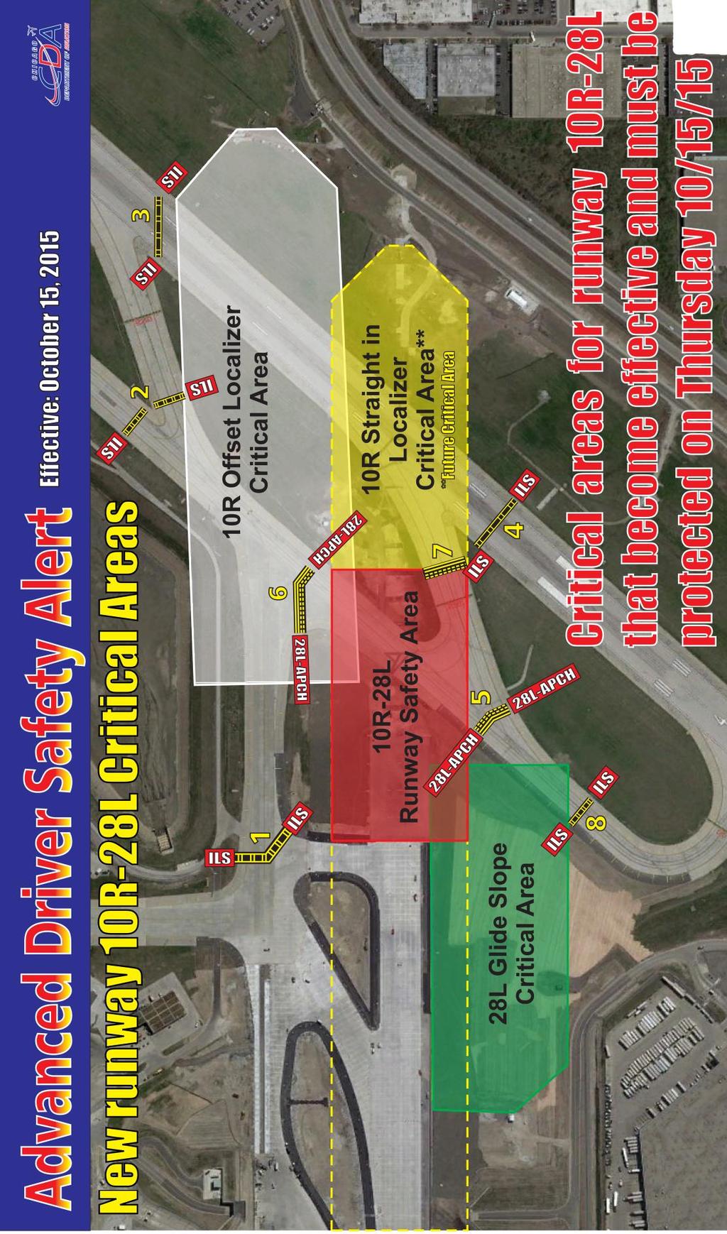
70 THINGS CHANGE BECOME FAMILIAR WITH NEW CHANGES Look at Graphic 1: Transponder Required Pavement for the control of Runway 9L-27R, the associated taxiways, and Runway 10R-28L. IMPORTANT! WITHOUT FAIL, NO EXCEPTIONS - YOU MUST HAVE AN OPERATIONAL TRANSPONDER ON TO DRIVE ON Twy C, C1, Z, and Rwy 9L-27R when they are OPEN! When in doubt, Call Airport Airfield Operations over the radio, or at , Before you drive onto Twy C, from Twy U, or Twy Z. Signs have been installed on Twy C, northwest of Twy U1, and on Twy Z, northwest corner. REMEMBER TO HAVE AN OPERATIONAL TRANSPONDER or NO ACCESS TO Twy Z, Twy C, Twy C1, Runway 9L-27R, or Runway 10R/28L while OPEN ILS CRITICAL AREAS: o Look at Graphic 2: Localizer Critical Areas in Red, Glide Slope Critical Areas in Blue. o If visibility is less than 2 miles and/or the ceiling is reported to be below All contractors and City vehicles MUST REMAIN CLEAR OF any of the ILS Critical Areas. o Operations in these areas will only be authorized by Airport Airfield Operations over the radio dependent on the runway configuration in use. o If in doubt, remain clear and confirm through Airport Airfield Operations at o BEFORE you drive onto the airfield - listen to the ATIS on Mhz or by calling and the ASOS at RUNWAY SAFETY AREAS (RSA S) o Look at Graphic 3: Three Runways at ORD Pass through another Runway s Safety Area and MUST be protected under certain circumstances. o If the runway you are on is open and controlled by the air traffic control tower (ATCT), then the tower will advise you where to hold short of, if necessary. If you are driving on Runway 4R/22L and the runway is closed but the tower is using Runway 10L/28R or Runway 10R/28L, call the tower to coordinate the crossing, and/or driving on Taxiway Y and using Runway 10R/28L, call the tower to coordinate the crossing. If you are driving on Runway 4R/22L the runway is closed and you need to exit on Taxiway Y5, but the tower is using Runway 10L/28R, call the tower to coordinate the crossing. Simply treat the situations mentioned above as if the runways intersected. The Driver is responsible to coordinate passing through the shadowed RSA s on Graphic 3, if the runway the driver is located on is closed but the intersecting RSA runway is open. 69

71 70
ICAO Recommended Airport Signs, Runway And Taxiway Markings. COPYRIGHT JEPPESEN SANDERSON, INC., ALL RIGHTS RESERVED. Revision Date:
 ICAO Recommended Airport Signs, Runway And Taxiway Markings Revision Date: 20051230 MANDATORY INSTRUCTION SIGNS A mandatory instruction sign identifies a location beyond which an aircraft taxiing shall
Driving Training Class. Presented by: Lancaster Airport Authority
 Driving Training Class Presented by: Lancaster Airport Authority Driving is a Privilege Driving on the airport, airport apron and ramps is a privilege and can be revoked at anytime for any reason. Violations
ICAO Standards. Airfield Information Signs. ICAO Annex 14, 4th Edition Aerodrome Design and Operations
 ICAO Standards Airfield Information Signs ICAO Annex 14, 4th Edition Aerodrome Design and Operations Federal Aviation Administration U.S. Department of Transportation February 2004 ICAO Standards This
print materials visit information on free live seminars, online courses, and
 The AOPA Air Safety Foundation is dedicated to making flying easier and safer for general aviation pilots. For information on free live seminars, online courses, and print materials visit. ILS Critical
AERODROME MARKINGS AND SIGNALIZATION
 1. Introduction AERODROME MARKINGS AND SIGNALIZATION This article will present the main aerodrome markings and signalization on runways and taxiways. 2. Runway Markings This chapter will show the runway
Source: Chippewa Valley Regional Airport ASOS, Period of Record
 Chapter 1 Inventory Runway wind coverage is the percentage of time a runway can be used without exceeding allowable crosswind velocities. Allowable crosswind velocities vary depending on aircraft size
Navigation - Runways. Chap 2, Nolan
 Navigation - Runways Chap 2, Nolan 1 Runways Runways numbered to correspond to magnetic bearing Runway 27 has magnetic bearing 270 degrees Active Runway selected for headwind greater than 5 knots When
MCAS CHERRY POINT. Basic Airfield Vehicle Operator Course (AVOC)
") MCAS CHERRY POINT Basic Airfield Vehicle Operator Course (AVOC) REFERENCES 1) FAA Handbook 7110.65 (ATC) 2) NAVAIR 00-80T-114 (ATC NATOPS) 3) MCO 1500.19 (Safety Program) 4) AirStaO P 3710.5 (AOM) 5) ATCFacO
MCAS CHERRY POINT Basic Airfield Vehicle Operator Course (AVOC) REFERENCES 1) FAA Handbook 7110.65 (ATC) 2) NAVAIR 00-80T-114 (ATC NATOPS) 3) MCO 1500.19 (Safety Program) 4) AirStaO P 3710.5 (AOM) 5) ATCFacO
VI.C. Airport, Runway and Taxiway Signs, Markings, and Lighting
 References: FAA-H-8083-23; FAA-H-8083-25; AIM; AC 150/5340-1; AC 150/5340-18 Objectives Key Elements Elements Schedule Equipment IP s Actions SP s Actions Completion Standards The student should develop
Runway and Taxiway Marking
 Lecture-38 10CV63 TE-II Runway and Taxiway Marking In order to aid pilots in guiding the aircraft on runways and taxiways, pavements are marked with lines and numbers. These markings are of benefit primarily
LANCASTER AIRPORT DRIVER TRAINING PROGRAM
 LANCASTER AIRPORT DRIVER TRAINING PROGRAM INTRODUCTION 1. Airfield Driving Basics 2. Movement / Non-Movement Area 3. Airfield Signs, Markings & Lighting 4. Airfield Communications 5. Aviation Phonetics
LANCASTER AIRPORT AIRPORT UTILIZATION BY VEHICLE OPERATORS
 LANCASTER AIRPORT AIRPORT UTILIZATION BY VEHICLE OPERATORS Revised: October 25, 1995 TABLE OF CONTENTS Airport Utilization by Vehicle Operators... Page 1 Communications Ideas and Practices... Page 2 Phonetic
SURFACE MOVEMENT GUIDANCE AND CONTROL SYSTEM PLAN. Los Angeles International Airport
 SURFACE MOVEMENT GUIDANCE AND CONTROL SYSTEM PLAN Los Angeles International Airport Surface Movement Guidance and Control System (SMGCS) Plan The SMGCS Plan for Los Angeles International Airport (LAX)
Appendix C AIRPORT LAYOUT PLANS
 Appendix C AIRPORT LAYOUT PLANS Appendix C AIRPORT LAYOUT PLANS Airport Master Plan Santa Barbara Airport As part of this Airport Master Plan, the Federal Aviation Administration (FAA) requires the development
Airport Operations. Chapter 14. Introduction. Airport Categories
 Chapter 14 Airport Operations Introduction Each time a pilot operates an aircraft, the flight normally begins and ends at an airport. An airport may be a small sod field or a large complex utilized by
RPL SYLLABUS CAMDEN RADIO PROCEDURES VERSION 1.0
 VERSION 1.0 Table of Contents Introduction... 3 Camden Airport... 3 Definitions... 4 Camden Airport Radio Frequencies... 5 Taxiing at Camden Airport... 5 Phonetic Alphabet and Numerals... 6 Radio Transmission
CHICO MUNICIPAL AIRPORT NON-MOVEMENT AREA DRIVER TRAINING PROGRAM
 CHICO MUNICIPAL AIRPORT NON-MOVEMENT AREA DRIVER TRAINING PROGRAM Introduction In an effort to provide the safest and most efficient operating environment for tenants and users of the Chico Municipal Airport
Aerodrome Standards and Requirements Aeroplanes at or below 5700 kg MCTOW Non Air Transport Operations
 Advisory Circular AC139-7 & AC91-15 Aerodrome Standards and Requirements Aeroplanes at or below 5700 kg MCTOW Non Air Transport Operations Revision 4 18 December 2009 General Civil Aviation Authority Advisory
Or visit our web site at
 Crossing Runways: If an aircraft is about to land on a runway you need to cross, stop and yield to the aircraft. Be aware that many pilots use airports without operating control towers for training purposes
Rules and Regulations
 APPENDIX 1 LOW-VISABILITY OPERATIONS/SURFACE MOVEMENT GUIDANCE AND CONTROL SYSTEM (LVO/SMGCS) PLAN TABLE OF CONTENTS TITLE PAGE 1.0 INTRODUCTION 2 2.0 DEFINITIONS 3 3.0 FACILITIES, SERVICES AND EQUIPMENT
DRAFT MASTER PLAN UPDATE
 DRAFT MASTER PLAN UPDATE CHAPTER VI: AIRPORT LAYOUT PLAN NARRATIVE DRAFT REPORT APRIL 2017 PREPARED BY: Table of Contents WESTCHESTER COUNTY AIRPORT 6 AIRPORT LAYOUT PLAN NARRATIVE REPORT... 6-1 6.1 AGIS
Movement Area Driver s Guide
 Welcome to Pensacola International Airport! Whether you are a new employee with no experience working in aviation or a seasoned veteran, our facility is truly a unique place that provides invaluable services
This advisory circular (AC) contains the Federal Aviation Administration (FAA) standards for markings used on airport runways, taxiways, and aprons.
 contains the Federal Aviation Administration (FAA) standards for markings used on airport runways, taxiways, and aprons.") U.S. Department of Transportation Federal Aviation Administration Advisory Circular Subject: Standards for Airport Markings Date: 9/27/2013 Initiated by: AAS-100 AC No: 150/5340-1L Change: 1. What is the
U.S. Department of Transportation Federal Aviation Administration Advisory Circular Subject: Standards for Airport Markings Date: 9/27/2013 Initiated by: AAS-100 AC No: 150/5340-1L Change: 1. What is the
Chapter The All-new, World-class Denver International Airport Identify Describe Know Describe Describe
 Chapter 10 The aerospace subject is very large and diverse. As seen in previous chapters, there are many subject areas. So far you have learned about history, weather, space and aerodynamics. Now you will
Section 32 TABLE OF CONTENTS Airfield and Aircraft Operations. 32.A General B Aircraft
 Section 32 TABLE OF CONTENTS Airfield and Aircraft Operations Section: Page 32.A General... 32-1 32.B Aircraft... 32-4 32-i THIS PAGE INTENTIONALLY LEFT BLANK 32-i SECTION 32 Airfield and Aircraft Operations
TABLE OF CONTENTS 1.0 INTRODUCTION...
 Advisory Circular Subject: Publication of the Level of Service with Respect to Departure Below RVR 2600 (½ Statute Mile) Issuing Office: Civil Aviation, Standards Document No.: AC 302-001 File Classification
RADIOTELEPHONY BASICS
 1. General operating procedures RADIOTELEPHONY BASICS Radiotelephony (RTF) provides the means by which pilots and ground personnel communicate with each other. The information and instructions transmitted
Runway Incursions 3 Markings
 Session Visual Aids Runway Incursions 3 Markings 3.12.2 A runway-holding position shall be established: a) on the taxiway, at the intersection of a taxiway and a runway; and b) at an intersection of a
National Transportation Safety Board Washington, D.C
 E PLURIBUS UNUM NATIONAL TRA SAFE T Y N S PORTATION B OAR D National Transportation Safety Board Washington, D.C. 20594 Safety Recommendation Date: June 25, 2004 In reply refer to: A-04-48 through -50
MOTOR VEHICLE OPERATING PERMIT PROGRAM (MVOP)
") MOTOR VEHICLE OPERATING PERMIT PROGRAM (MVOP) STUDY GUIDE PRODUCED BY VAN NUYS AIRPORT OPERATIONS JANUARY 2018 INTENTIONALLY LEFT BLANK Introduction In an effort to provide the safest and most efficient
MOTOR VEHICLE OPERATING PERMIT PROGRAM (MVOP) STUDY GUIDE PRODUCED BY VAN NUYS AIRPORT OPERATIONS JANUARY 2018 INTENTIONALLY LEFT BLANK Introduction In an effort to provide the safest and most efficient
Brunswick Executive Airport. Airport Safety Program
 Brunswick Executive Airport Airport Safety Program Why Runway Incursions FY 14 FY 13 FY 12 FY 11 1 st Quarter 298 273 226 215 2 nd Quarter 258 287 267 246 3 rd Quarter 359 328 352 257 4 th Quarter 349
DALLAS/FORT WORTH INTERNATIONAL AIRPORT SURFACE MOVEMENT GUIDANCE AND CONTROL SYSTEM SMGCS PLAN FOR ARRIVAL RUNWAYS 17L-35R, 17C-35C, AND 18R
 DALLAS/FORT WORTH INTERNATIONAL AIRPORT SURFACE MOVEMENT GUIDANCE AND CONTROL SYEM SMGCS PLAN FOR ARRIVAL RUNWAYS 7L-35R, 7C-35C, AND 8R DEPARTURE RUNWAYS 7R-35L AND 8L-36R Published September 30, 20 (Reviewed
SECTION 32. Airfield and Aircraft Operations
 SECTION 32 Airfield and Aircraft Operations 32.A Airfields General. 32.A.01 The following safety requirements shall be in addition to the airfield's safety requirements. When an airfield has safety requirements
Ref. AIM Para AOPA Air Safety Foundation Supported by the FAA Ref. AIM Para Supported by the FAA
 ILS Critical Area Holding Position Sign: ATC may hold you at this sign, on a taxiway, when the instrument landing system is being used at the airport. Aircraft taxiing beyond this point may interfere with
GTR Movement Area Drivers Training Manual
 GTR Movement Area Drivers Training Manual TABLE OF CONTENTS: Introduction.2 Basic parts of an airport.2 Non-Movement Area...3 Movement Areas. 4 Aircraft Operations 7 Control Tower Operations. 9 Uncontrolled
APPENDIX C AIRSPACE PROCEDURES
 APPENDIX C AIRSPACE PROCEDURES This appendix is designed to provide the reader with an introduction to how aircraft operate in and around Cincinnati/Northern Kentucky International Airport (CVG), the facilities
Location, Identity, Specific Location, Intention, Location Again
 I. PEDESTRIAN AND GROUND VEHICLE RULES AND INFORMATION The Sanford Seacoast Regional Airport (SFM) is a nontowered airport, meaning it has no air traffic control tower. Any vehicle authorized to operate
SITE ELEVATION AMSL...Ground Elevation in feet AMSL STRUCTURE HEIGHT...Height Above Ground Level OVERALL HEIGHT AMSL...Total Overall Height AMSL
 ******************************************** * Federal Airways & Airspace * * Summary Report * ******************************************** File: User Assigned File Name Latitude: NAD83 Coordinate Longitude:
1.1.3 Taxiways. Figure 1-15: Taxiway Data. DRAFT Inventory TYPICAL PAVEMENT CROSS-SECTION LIGHTING TYPE LENGTH (FEET) WIDTH (FEET) LIGHTING CONDITION
 WIDTH (FEET) LIGHTING CONDITION") 1.1.3 Taxiways EWN has an extensive network of taxiways and taxilanes connecting the terminal, air cargo, and general aviation areas with the runways as listed in Figure 1-15. A 50-foot wide parallel taxiway
1.1.3 Taxiways EWN has an extensive network of taxiways and taxilanes connecting the terminal, air cargo, and general aviation areas with the runways as listed in Figure 1-15. A 50-foot wide parallel taxiway
Runway Safety Awareness Guide Incorporating Airside Driving Authority Category 3 & 4
 Runway Safety Awareness Guide Incorporating Airside Driving Authority Category 3 & 4 July 2017 Runway Safety Awareness Guide a b Runway Safety Awareness Guide Contents Introduction 2 Aerodrome Hazards
AIRPORTS There are two types of airport environments: controlled and uncontrolled. A controlled airport has an operating control tower, staffed by
 AIRPORTS There are two types of airport environments: controlled and uncontrolled. A controlled airport has an operating control tower, staffed by either Federal or privately-contracted air traffic controllers.
AERODROME LIGHTING SYSTEM
 AERODROME LIGHTING SYSTEM 1. Introduction This chapter will show the wide variety of approach lighting systems before the runway threshold and systems present on runways. 2. Runway approach ramps 2.1.
DEPARTMENT: CIVIL ENGINEERING SEMESTER: III SUBJECT CODE / Name: CE2303/ Railway, Airport and Harbors Engineering 2 MARK QUESTIONS AND ANSWERS
 DEPARTMENT: CIVIL ENGINEERING SEMESTER: III SUBJECT CODE / Name: CE2303/ Railway, Airport and Harbors Engineering 2 MARK QUESTIONS AND ANSWERS 1.Define wind Coverage (AUC NOV/DEC 2010),(AUC NOV/DEC 2011)
a. Aeronautical charts DID THIS IN LESSON 2
 AIRMAN CERTIFICATION STANDARDS: REMOTE PILOT SMALL: You will know and be able to explain in writing or oral form the below tasks regarding AIRPORT OPERATIONS Task References Objective Task B. Airport Operations
Runway Excursion 2018 projects ALTA 2018
 Runway Excursion 2018 projects ALTA 2018 Mayor cities workshops Pilots and controller's simulator section visit Proposed cities Miami, Mexico City, El Salvador, San Jose, Panama City, Bogota, Lima, Santiago,
Subject: Standards for Airport Markings Date: 9/3/2010 AC No: 150/5340-1K Initiated by: AAS-100 Change:
 Consolidated AC includes Change 1 U.S. Department of Transportation Federal Aviation Administration Advisory Circular Subject: Standards for Airport Markings Date: 9/3/2010 AC No: 150/5340-1K Initiated
RUNWAY INCURSION PREVENTION PROGRAM ICAO NAM/CAR/SAM RUNWAY SAFETY/INCURSION CONFERENCE Mexico City, 22 to 25 October 2002
 RUNWAY INCURSION PREVENTION PROGRAM ICAO NAM/CAR/SAM RUNWAY SAFETY/INCURSION CONFERENCE Mexico City, 22 to 25 October 2002 I n t e r n a t i o n a l A i r T r a n s p o r t A s s o c i a t I o n I A T
MCAS CHERRY POINT. Basic Airfield Vehicle Operator Course (AVOC)
") MCAS CHERRY POINT Basic Airfield Vehicle Operator Course (AVOC) REFERENCES 1) FAA Handbook 7110.65 2) NAVAIR 00-80T-114 3) MCO 1500.19 4) AirStaO P 3710.5 5) ATCFacO P3722.1 PURPOSE The purpose of the
MCAS CHERRY POINT Basic Airfield Vehicle Operator Course (AVOC) REFERENCES 1) FAA Handbook 7110.65 2) NAVAIR 00-80T-114 3) MCO 1500.19 4) AirStaO P 3710.5 5) ATCFacO P3722.1 PURPOSE The purpose of the
VISUAL AIDS SYSTEM. REFERENCE This Advisory Circular relates specifically to the Aerodrome GCARs and Manual of Standards (MOS)
") AC-AD-027 VISUAL AIDS SYSTEM GENERAL The Ghana Civil Aviation Authority (GCAA) Advisory Circulars from Aerodrome Safety and Standards (ASAS) contain information about standards, practices and procedures
AC-AD-027 VISUAL AIDS SYSTEM GENERAL The Ghana Civil Aviation Authority (GCAA) Advisory Circulars from Aerodrome Safety and Standards (ASAS) contain information about standards, practices and procedures
GRANDE PRAIRIE AIRPORT. Reduced Visibility Operations Plan
 GRANDE PRAIRIE AIRPORT Reduced Visibility Operations Plan Amended November 8, 2017 Distribution List: (Updates to the Reduced Visibility Operations Plan will be circulated to this list.) Name and Title
WFC HANGER TALK SERIES This Event - Mean what you say : say what you mean Control Tower Procedures Prep for Simulator Exercise
 Challenge for the Simulator portion of the event get out of the plane and into the Control Tower BACKGROUND INFORMATION RUNWAY SELECTION Assign the operationally suitable runway most nearly aligned into
Chapter Six ALP Drawings. Tacoma Narrows Airport. Master Plan Update
 Chapter Six ALP Drawings Master Plan Update The master planning process for the (Airport) has evolved through efforts in the previous chapters to analyze future aviation demand, establish airside and landside
Session Best Practices Amendments From Annex14, Volume I Annex 15. Runway Incursions Runway Excursions
 Session Best Practices Amendments From Annex14, Volume I Annex 15 Runway Incursions Runway Excursions Annex 15 AIP - Member States Report: Installation of ARRESTOR SYSTEMS Location - Runway End Industry
TECHNICAL REPORT #7 Palm Beach International Airport Airport Layout Plan
 TECHNICAL REPORT #7 Palm Beach International Airport Airport Layout Plan Technical Report #7 Palm Beach International Airport Layout Plan Palm Beach International Airport Prepared for Palm Beach County
 Telephone No. 2:4622495 Telegraphic Address: Commercial : AIRCIVIL NEW DELHI Aeronautical : VIDDYAYX E Mail: dri@dgca.nic.in Fax : 01124629221 GOVERNMENT OF INDIA AERONAUTICAL INFORMATION SERVICES DIRECTOR
1) Rescind the MOD (must meet the standard); 2) Issue a new MOD which reaffirms the intent of the previous MOD; 3) Issue a new MOD with revisions.
 Rescind the MOD (must meet the standard); 2) Issue a new MOD which reaffirms the intent of the previous MOD; 3) Issue a new MOD with revisions.") ALBUQUERQUE INTERNATIONAL SUNPORT AIRCRAFT HOLD LINE LOCATION ANALYSIS WHITE PAPER JUNE 24, 2016 HOLD LINE LOCATION ISSUE The location of many of the taxiway hold lines at the Sunport do not meet current
ALBUQUERQUE INTERNATIONAL SUNPORT AIRCRAFT HOLD LINE LOCATION ANALYSIS WHITE PAPER JUNE 24, 2016 HOLD LINE LOCATION ISSUE The location of many of the taxiway hold lines at the Sunport do not meet current
TRAFFIC CONTROL DEVICES MANUAL FOR WORK ZONES
 TRAFFIC CONTROL DEVICES MANUAL FOR WORK ZONES SUMMARY Work zone activities often create conditions on the travelled way that are hazardous particularly at night when the ability of motorists to see is
APPENDIX D FEDERAL AVIATION REGULATIONS, PART 77
 APPENDIX D FEDERAL AVIATION REGULATIONS, PART 77 Subparts A through C PART 77 - OBJECTS AFFECTING NAVIGABLE AIRSPACE Subpart A General 77.1 Scope. 77.2 Definition of terms. 77.3 Standards. 77.5 Kinds of
 IFR 91.157 Must be instrument rated to fly special VFR at Night (civil twilight to civil twilight, sun 6 degrees below horizon) 91.159 Unless in a holding pattern of 2 minutes or less, VFR cruising altitude
The following criteria shall be applied within the boundaries of the AO District:
 Sec. 419 (a) Purpose AIRPORT OVERLAY DISTRICT (AO) The purpose of the Airport Overlay District is to regulate and restrict the height of structures, objects, or natural growth, regulate the locations of
DEPARTMENT: CIVIL ENGINEERING SEMESTER: III SUBJECT CODE / Name: CE2303/ Railway, Airport and Harbors Engineering
 DEPARTMENT: CIVIL ENGINEERING SEMESTER: III SUBJECT CODE / Name: CE2303/ Railway, Airport and Harbors Engineering 1.Landing direction indicator UNIT 4 TWO MARK QUESTIONS AND ANSWERS Two mark question with
Airport Obstruction Standards
 Airport Obstruction Standards Dr. Antonio Trani Department of Civil and Environmental Engineering Virginia Tech Outline of this Presentation Obstructions to navigation around airports Discussion of Federal
Appendix 6.1: Hazard Worksheet
 Appendix 6.1: Appendix 6.1: Ref. Condition, real or potential; that can cause injury, illness, etc. This is a prerequisite for an Airfield Hazards 1. Taxiway Geometry Direct access to runway from ramp
II.B. Runway Incursion Avoidance
 References: AC 91-73 Objectives Key Elements Elements Schedule Equipment IP s Actions SP s Actions Completion Standards The student should develop knowledge of the elements related to proper incursion
Appendix D Airfield Ongoing Projects Alternatives
 Appendix D Appendix D D.1 Introduction The set of alternatives for each of the airfield facilities was compared with respect to each other and the existing condition. 1 The screening and evaluation process
THE VILLAGES AVIATION CLUB. SAFETY BRIEF November 2016
 THE VILLAGES AVIATION CLUB SAFETY BRIEF November 2016 Welcome Back Snowbirds When are you going home? If you see a man wearing a hat like this, go over and say Welcome Home. You ll make his day. Sure,
Hartford-Brainard Airport Potential Runway Closure White Paper
 Hartford-Brainard Airport Potential Runway 11-29 Closure White Paper June 2012 In recent years there has been discussion regarding the necessity of Runway 11-29 to the Hartford- Brainard Airport (HFD)
USE OF RADAR IN THE APPROACH CONTROL SERVICE
 USE OF RADAR IN THE APPROACH CONTROL SERVICE 1. Introduction The indications presented on the ATS surveillance system named radar may be used to perform the aerodrome, approach and en-route control service:
CATCODE ] CATCODE
![CATCODE ] CATCODE](/thumbs/82/85644630.jpg "CATCODE ] CATCODE") Runways. FAC: 1111 CATCODE: 111111 OPR: AFCEC/COS OCR: AF/A3O-A 1.1. Description. The runway is the paved surface provided for normal aircraft landings and take offs. Runways are classified as either Class
Runways. FAC: 1111 CATCODE: 111111 OPR: AFCEC/COS OCR: AF/A3O-A 1.1. Description. The runway is the paved surface provided for normal aircraft landings and take offs. Runways are classified as either Class
Consideration will be given to other methods of compliance which may be presented to the Authority.
 Advisory Circular AC 139-10 Revision 1 Control of Obstacles 27 April 2007 General Civil Aviation Authority advisory circulars (AC) contain information about standards, practices and procedures that the
Table of Contents. List of Tables. Cincinnati/Northern Kentucky International Airport 2035 Master Plan Update
 Table of Contents 7.1. Airport Layout Plan (Existing Conditions)... 2 7.2. Airport Layout Plan (Future Conditions)... 3 7.3. Technical Data Sheet... 5 7.4. Commercial Terminal Area Drawing... 5 7.5. East
Chapter 9 - AIRPORT SYSTEM DESIGN
 Chapter 9 - AIRPORT SYSTEM DESIGN 9.01 GENERAL This chapter discusses the development program for Dutchess County Airport to the year 2020. This airport system design is based upon the airport's existing
CHAPTER FOUR AIRPORT ALTERNATIVES
 4.0 INTRODUCTION CHAPTER FOUR The goal of the master planning process is to provide the City of New Smyrna Beach with an assessment of the adequacy and capabilities of the Airport as well as to identify
Airport Design-3 Geometric Design
 Airport Design-3 Geometric Design When designing airport runways, engineers and other planners have many factors to consider. These include the type and volume of air traffic, the impact of noise, and
INCREASING AIRPORT OPERATION SAFETY BASED ON UPDATED OR ENHANCED AIRPORT PAVEMENT MARKINGS: A CASE STUDY PAPER
 INCREASING AIRPORT OPERATION SAFETY BASED ON UPDATED OR ENHANCED AIRPORT PAVEMENT MARKINGS: A CASE STUDY PAPER 09-2020 By Chun-Hsing Ho, Dwight D. Eisenhower Fellow Department of Civil and Environmental
NAVIGATION: CHARTS, PUBLICATIONS, FLIGHT COMPUTERS (chapters 7 & 8)
") NAVIGATION: CHARTS, PUBLICATIONS, FLIGHT COMPUTERS (chapters 7 & 8) LONGITUDE AND LATITUDE 1. The location of an airport can be determined by the intersection of lines of latitude and longitude. a. Lines
NAVIGATION: CHARTS, PUBLICATIONS, FLIGHT COMPUTERS (chapters 7 & 8) LONGITUDE AND LATITUDE 1. The location of an airport can be determined by the intersection of lines of latitude and longitude. a. Lines
FAA Office of Airport Safety and Standards
 FAA Office of Airport Safety and Standards Airport and Runway Safety and Technology Presented to: Pan American Regional Aviation Safety Team (PA-RAST) By: Michael Meyers, Deputy Manager Airport Engineering
AERODROME CHART ATIS CLNC DEL 121.4
 AERODROME CHART ATIS 124.6 CLNC DEL 121.4 GND 121.7 (S) 127.15 (N) 275.8 -AD TWR 118.7 (S) 119.55 (N) 226.5 DEP 126.12 (N) 132.3 (S) 363.8 DECL DISTS 08R 26L 08L 26R 13 31 TORA 11500 11500 9940 9940 7300
Airservices Australia. Copyright
 AIP Australia 23 AUG 12 AD 0.6-1 PART 3 - AERODROMES (AD) AD 0. AD 0.1 AD 0.2 AD 0.3 AD 0.4 AD 0.5 PREFACE - Not applicable RECORD OF AIP AMENDMENTS - Not applicable RECORD OF AIP SUPPLEMENTS - Not applicable
THE VILLAGES AVIATION CLUB. November 2014 SAFETY BRIEF
 THE VILLAGES AVIATION CLUB November 2014 SAFETY BRIEF IT WAS DARK, VERY DARK SO LETS GO FLYING SURE, YOU GET AN EXTRA HOURS SLEEP, BUT WHEN DO YOU GO FLYING? REVIEW OF NIGHT FLYING REGS AND TIPS Night
Radio + Air Law Oct. 26
 Manuals and Books pg. 107 Radio + Air Law Oct. 26 1. Canadian Aviation Regulation Contains all the rules and regulations pertaining to operation of aircraft in Canada. Some topics include: licensing, registration,
Appendix B Ultimate Airport Capacity and Delay Simulation Modeling Analysis
 Appendix B ULTIMATE AIRPORT CAPACITY & DELAY SIMULATION MODELING ANALYSIS B TABLE OF CONTENTS EXHIBITS TABLES B.1 Introduction... 1 B.2 Simulation Modeling Assumption and Methodology... 4 B.2.1 Runway
RADIO COMMUNICATIONS AND ATC LIGHT SIGNALS
 RADIO COMMUICATIOS AD ATC LIGHT SIGALS VI - A ITRODUCTIO RADIO LICESE RADIO EQUIPMET PHRASEOLOGY LOST COMMUICATIO Receiver Transmitter Both Departure - Operating in and out of a controlled airport, as
BELFAST MUNICIPAL AIRPORT OVERVIEW
 BELFAST MUNICIPAL AIRPORT OVERVIEW LOCATION AND HISTORY Belfast Municipal Airport (Federal Aviation Administration (FAA) airport code BST, International Civil Aviation Organization airport code KBST, FAA
Draft Concept Alternatives Analysis for the Inaugural Airport Program September 2005
 Draft Concept Alternatives Analysis for the Inaugural Airport Program September 2005 Section 1 - Introduction This report describes the development and analysis of concept alternatives that would accommodate
RULES OF TENNESSEE DEPARTMENT OF TRANSPORTATION AERONAUTICS DIVISION CHAPTER LICENSING AND REGISTRATION OF AIRPORTS TABLE OF CONTENTS
 RULES OF TENNESSEE DEPARTMENT OF TRANSPORTATION AERONAUTICS DIVISION CHAPTER 1680-1-2 LICENSING AND REGISTRATION OF AIRPORTS TABLE OF CONTENTS 1680-1-2-.01 Purpose 1680-1-2-.06 Repealed 1680-1-2-.02 Definitions
Appendix A - Glossary
 Appendix A - Glossary The terms and definitions here are relevant to airport design standards and retrieved from AC 150/5300-13A, Airport Design. A Accelerate-Stop Distance Available (ASDA). See Declared
Chapter 6. Nonradar. Section 1. General DISTANCE
 12/10/15 JO 7110.65W Chapter 6. Nonradar Section 1. General 6 1 1. DISTANCE Use mileage based (DME and/or ATD) procedures and minima only when direct pilot/controller communications are maintained. FIG
PROPOSED HORIZONTAL LAYOUT FILLET DESIGN FOR ENTRANCE/EXIT TAXIWAYS
 PROPOSED HORIZONTAL LAYOUT FILLET DESIGN FOR ENTRANCE/EXIT TAXIWAYS INTRODUCTION The Zelienople Airport Authority (ZAA) has commenced engineering activities for the rehabilitation of Runway 17-35 to a
Draft Concept Alternatives Analysis for the Inaugural Airport Program September 2005
 Draft Concept Alternatives Analysis for the Inaugural Airport Program September 2005 Section 3 - Refinement of the Ultimate Airfield Concept Using the Base Concept identified in Section 2, IDOT re-examined
Airport Operations. Chapter 13. Gold Seal Online Ground School Introduction. Types of Airports
 Chapter 13 Airport Operations Gold Seal Online Ground School www.onlinegroundschool.com Introduction Each time a pilot operates an aircraft, the flight normally begins and ends at an airport. An airport
Safety, Infrastructure, and Tenant Improvement Project. Public Hearing Informational Brochure February 26, 2013
 New York State Department of Transportation Safety, Infrastructure, and Tenant Improvement Project Public Hearing Informational Brochure February 26, 2013 This DEIS/Draft EA evaluates the potential impacts
AD 2. AERODROMES. For the ICAO location indicators used for Canadian aerodromes, refer to the following publications:
 AIP CANADA (ICAO) PART 3 AERODROMES (AD) AD 2. AERODROMES AD 2.1 Aerodrome Location Indicator and Name For the ICAO location indicators used for Canadian aerodromes, refer to the following publications:
MANCHESTER AIRPORT AIRCRAFT PUSHBACK PROCEDURES. Effective from 27th November :01 hrs local.
 MANCHESTER AIRPORT AIRCRAFT PUSHBACK PROCEDURES Effective from 27th November 2018. 00:01 hrs local. Operational changes from previous revision; TRPs 216 and NA permanently withdrawn from use. Choice of
ORDINANCE NO. _2013-
 ORDINANCE NO. _2013- AN ORDINANCE OF THE TOWNSHIP OF CONEWAGO, DAUPHIN COUNTY, PENNSYLVANIA, PROVIDING FOR AIRPORT ZONING REGULATIONS WITHIN THE AIRPORT ZONING OVERLAY DISTRICT CREATED BY THIS ORDINANCE
DIRECCION DE PERSONAL AERONAUTICO DPTO. DE INSTRUCCION PREGUNTAS Y OPCIONES POR TEMA
 T E M : 0322 INSTRUTOR_DVNED_07_PROEDURES & IRPT OPS OD_PREG: P R E G U N T : RPT: 6436 n airport without a control tower lies within the controlled airspace of an airport with an operating tower. ccording
Office of Airport Safety and Standards
 Office of Airport Safety and Standards Airport Lighting Program To: By: Illuminating Engineering Society Aviation Lighting Committee Government Contacts Subcommittee Michael O Donnell, Director Office
2. CANCELLATION. Advisory Circular 150/5340=18B, Standards for Airport Sign Systems, dated August 21,
 U.S. Department of lfanspoftatii Federal Aviation Administration Circular REPRINT INCORPORATES CHANGE 1 4 4 Subject: STANDARDS FOR AIRPORT SIGN SYSTEMS Date: 7/31/91 AC No: 150/534048C initiated by: AM-4
Las Vegas McCarran International Airport. Capacity Enhancement Plan
 Las Vegas McCarran International Airport Capacity Enhancement Plan Las Vegas McCarran International Airport Capacity Enhancement Plan September 1994 Prepared jointly by the U.S. Department of Transportation,
LFMN / Nice Côte-d Azur / NCE
 This page is intended to draw commercial and private pilots attention to the aeronautical context and main threats related to an aerodrome. They have been identified in a collaborative way by the main