Movement Area Driver s Guide
|
|
|
- Patrick Mathews
- 6 years ago
- Views:
Transcription
1 Welcome to Pensacola International Airport! Whether you are a new employee with no experience working in aviation or a seasoned veteran, our facility is truly a unique place that provides invaluable services to millions of people visiting Florida s Gulf Coast. Because Pensacola International Airport is distinct and configured unlike any other airport in the world, this driver s guide consisting of site-specific information about the operational environment has been developed in order to provide basic orientation. This guide has been designed to provide the fundamental information needed to safely drive at the airport and is intended to complement the necessary practical hands on training provided by your employer. Because the day-to-day working environment is ever changing, it is extremely important that you take the time to individually educate yourself of safety specifics, regardless of your experience level or background. The most important attribute of a qualified airport driver is situational awareness based upon a solid understanding of the rules. All State and County laws which apply to the operations of vehicles on the roads and streets in the City are applicable to vehicles operating in the Air Operations Area or AOA. Additionally, the following is a synopsis of the airport rules and regulations which specifically apply to vehicles operating on the AOA. Section 1. DEFINITIONS The following words and phrases when used in this manual shall have the following meanings: 1. Accident. An event which involves at least one or more vehicles, injury or property damage. 2. Aircraft. A device that is used or intended to be used for flight in the air. 3. Air Operations Area (AOA). Any area of the airport used or intended to be used for landing, taking off or surface maneuvering of aircraft within the Airport Security Perimeter. It is intended for use by persons for the operation of aircraft, ground support vehicles, and other authorized vehicles related to airport operations, and includes all exclusive leasehold areas as well as the Tug Drive. 4. Airport. Pensacola International Airport, a public airport under the supervision and control of the City of Pensacola, and located in the County of Escambia and State of Florida. 5. Airport Badging Office (ABO). The office that is responsible for Driver s training, testing, licensing and/or administration of this procedure. In addition, documentation of driver s training tests are maintained here. 6. Airport Director. The administrative officer or the officer's designee and, for purposes of the control of vehicles and enforcement of this procedure, the department head of the City of Pensacola in charge of the airport. 7. Airport Operations Center (AOC). The central office that handles items including tracking flights, security issues, emergency calls, dispatching police/maintenance/operations, inputting work orders and customer service for internal and external customers. 8. Air Traffic Control Tower (ATCT). A central operations facility in the air traffic control system, consisting of a tower cab, including an associated room using air/ground communications and/or radar, visual signaling and other devices, to provide safe and expeditious movement of terminal air traffic. This facility is operated by the Federal Aviation Administration (FAA), and is commonly referred to as the Tower. 1
2 9. Authorized Emergency Vehicle. Any of the following vehicles when equipped and identified according to law: (1) a vehicle of a fire department; (2) a publicly-owned police vehicle or a privately-owned vehicle used by a police officer for police work; (3) a publicly or privately owned licensed emergency ambulance; (4) an emergency vehicle of a municipal department or a public service corporation; (5) a vehicle designated as an Authorized Emergency Vehicle upon a finding by the Pensacola International Airport whereby that vehicle is necessary to the preservation of life or property or to the execution of emergency governmental functions. 10. Baggage Cart. Every non-motorized device, which is pulled by a vehicle and designed to transport aviation cargo, luggage or mail. 11. Breezeway. Two areas located under the concourse. One Breezeway is located between Gates 1 and 3 to between Gates 2 and 4. This is where the tricherator is located. The second Breezeway is located between Gates 5 and 7 to between Gates 6 and Designated Roadway / Motor Vehicle Lanes. Any portion of the AOA marked by two parallel white lines designed primarily for the safe and orderly movement of vehicles. 13. Driver. The person in operating control of a vehicle. 14. Escort. Authorized person(s) in possession of a valid NMA or MA designer on their badge who is responsible for accompanying, monitoring, directing and controlling the actions of a person(s) on the Non-Movement Area or Movement Area who is not in possession of a valid designation. The authorized person(s) must be accompanying the person for performance of direct job duties. 15. Flight Crew. Pilot, flight engineer or flight navigator assigned to duty during aircraft flight arrival or departure time. 16. Foreign Object Debris (FOD). A substance or article alien to aircraft or system that has potential to cause damage. Examples includes broken pavement, aircraft parts, tools, garbage, or any loose material lying on an apron, taxiway or runway. 17. Gate. An area of the AOA specifically designated and made available for the sole use of parking by an Aircraft. 18. Marshaller. A person who directs aircraft as it moves to or from a gate. 19. Movement Area. All runways and taxiways. Entrance is marked with a boundary marking with one solid yellow line and one dashed yellow line. 20. Movement Area Incursion. The crossing or entering of any open Movement Area, without positive clearance from the Air Traffic Control Tower or proper escort. 21. Non-Movement Area. All parking areas, cargo areas, service roads, ramps and all those areas within the AOA that are not specifically designated as Movement Area. 22. Parking. The standing of a vehicle upon a street, road or highway, parking area, aircraft loading ramp, service area, runway, taxiway or feeder whether accompanied or unaccompanied by the operator. 23. Passenger Loading Bridge. A device used to enplane and deplane passengers from the aircraft door to the terminal. 24. PNS Driver s Designator. A designator (NMA or MA) issued by the ABO authorizing persons to operate a vehicle in the Non-Movement Area or Movement Area. This designator can be suspended or revoked for violations of this procedure. 2
3 25. PNS Representative. Any person(s) authorized by the Airport Director to direct or coordinate driver safety at the airport, including but not limited to the Airport Operations and Airport Police Divisions. 26. Powerback. A procedure where aircraft back up under their own power using reverse engine thrust. 27. Pushback. A procedure where aircraft back up under the power of another vehicle. 28. Ramp Areas. Portions of the airport designated and made available, temporarily or permanently, for the loading and unloading of passengers or cargo on and off aircraft. 29. Right-of-Way. The privilege of the immediate use of a street, road, highway, gate, ramp area, taxiway or runway. In the Movement Area and Non-Movement area, aircraft always have the right-of-way. 30. Runway. A defined rectangular area prepared for landing and takeoff of aircraft along its length. This surface includes the associated safety area. 31. Runway Incursion. The entering of any runway, without positive clearance from the Air Traffic Control Tower. 32. Safety Area. A designated area abutting the edges of a runway or taxiway intended to reduce the risk of damage to an aircraft inadvertently leaving the runway or taxiway. 33. Security Perimeter. That portion of the airport which is enclosed by fencing, walls or other barriers and to which access is controlled through designated entry points. 34. Taxiway. A defined path used by aircraft to travel between the ramps and the runways. Taxiways have yellow paint markings and blue edge lights. Pensacola International Airport has four taxiways, A, B, C and D. 35. Tug Drive. The roadway behind the Terminal Building used for baggage handling and parking of vehicles. 36. Vehicle. Every device upon which any person or property may be transported or drawn upon land. This includes baggage carts, trailers and any other device designed to be towed by a vehicle. Vehicle excludes aircraft except for any aircraft that is being towed or operated by non-flight crew person(s). Aircraft taxiing operations are not covered under this definition. 3
4 Section 2. DRIVER REQUIREMENTS AND RESPONSIBILITIES A. Requirements 1. Complete the non-movement area test. 2. Possess a valid state driver s license or a limited state driver s license. 3. Meet the identification requirements in accordance with the Airport Security Program and be authorized for regular access to the AOA under such security program in order to be in the AOA. 4. Complete the Movement Area test to demonstrate the driver s knowledge of the airport, traffic and safety rules for the MA and the requirements of this manual. 5. Complete MA driver s training at least every 12 consecutive calendar months. B. Responsibilities 1. No driver shall operate and no person shall allow a driver to operate a vehicle on the Movement Area without a current, valid PNS MA designation or be escorted by a person with a valid PNS MA designation. 2. Demonstrate an ability to read, speak, and understand the English language so that he/she can communicate with controlling agencies. 3. Carry his/her state driver s license at all times while operating on the AOA and show their license to a PNS Representative upon request. 4. No driver shall take any actions that threaten the safety of PNS Representatives, cause harm to a PNS Representative, or interfere with the safety and efficiency of airport operations. 5. Each driver must successfully complete MA driver s training at least once every 12 consecutive calendar months. 6. All drivers must immediately report all vehicle accidents to the Airport Operations Center (AOC) by calling (850)
5 Airport Diagram 5
6 Section 3. MOVEMENT AREA The Movement Area includes all taxiways, runways and associated safety areas at PNS. Extreme caution needs to be exercised when driving on these surfaces. Taxiways and runways are the primary surfaces for the movement of aircraft. When driving on the Movement Area, aircraft always have the right-of-way. See Airfield Layout figure and Figure 1-2. A. Taxiways A taxiway is a surface designed to provide access to and from the runways and other areas of the airport, including the terminal area. Taxiways are a system of roads for aircraft by which they get to and from aprons and runways. Authorized vehicles are permitted to drive on taxiways for emergency response, operational necessity and training purposes only. Driving on taxiways for point-to-point travel for the sole purposes of convenience sake and saving travel time is not permitted. Vehicles must use the perimeter roadway where it is available. At PNS there are 4 taxiways: A Alpha B Bravo C Charlie D Delta B. Taxiway Feeders There are points of access along the taxiways for entering and exiting the runways and ramps. These points of access are called feeders. The feeders for taxiways at PNS are as follows: A A1, A2, A3, A4, A5, A6, A7 B B1, B2, B3, B4, B5, B6, B7, B8 C C1, C2 D D1, D2, D3, D4, D5 C. Taxiway Safety Areas Taxiways Alpha and Bravo at PNS are 75 feet while taxiways Charlie and Delta are 35 feet wide. All taxiways at PNS have a Safety Area surrounding them. The safety area is an area provided to minimize the probability of serious damage to aircraft accidentally entering these areas. All vehicle operators need to be aware that these areas exist and should use caution when operating in and around them. The safety area should be visualized as an imaginary surface centered directly over the taxiway. These areas are either 79 or 171 feet wide. This means that if the taxiway is 75 feet wide and the safety area is 171 feet wide, the safety area extends out 85.5 feet from the taxiway centerline. 6
7 7
8 Airfield Layout 8


9 75 foot wide taxiways Movement Area Driver s Guide 35 foot wide taxiways D. Runways 9
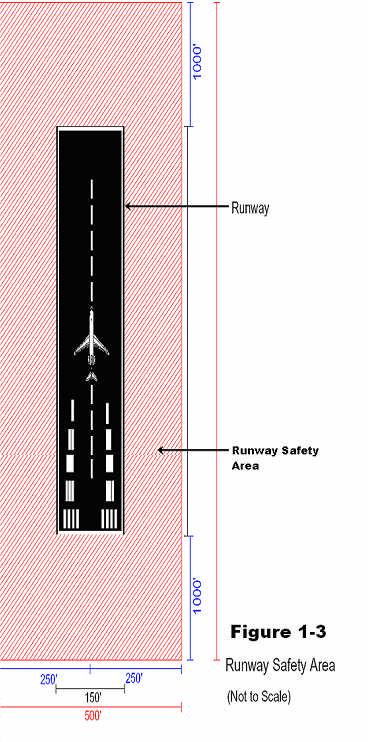
10 D. Runways There are only two pieces of pavement that make up the runways at PNS. However, since aircraft can depart and arrive from both ends, there are four runway designators. Prior to entry onto any runway, positive communications contact needs to be established with the ATCT. Without authorization, entry onto a runway is prohibited and is considered a runway incursion. Vehicles are permitted to cross open runways only for emergency response, operational necessity and training. These restrictions apply to all open runways at PNS. Runway crossings for point-to-point travel for the sole purposes of convenience sake and saving travel time are not permitted, even if the runway is closed. Vehicles must use the perimeter roadway where it is available. A runway is a rectangular area prepared for landing and takeoff of aircraft. At PNS there are two runways and four runway ends: 17, 35, 08 and 26. Runway Numbering A runway is usually aligned with the prevailing winds. Runways are numbered in relation to their magnetic heading, rounded off to the nearest 10 degrees. For example, runway 17 is numbered this way because it is 170 degrees, +/- 5 degrees, from magnetic north. Runway 35 is 350 degrees, +/- 5 degrees, from magnetic north and is exactly 180 degrees from 17. Runways 08 and 26 are 080 degrees and 260 degrees +/- 5 degrees from magnetic north respectively. Runway Dimensions Runway 17/35 is 7,004 feet long and 150 feet wide. Runway 08/26 is 7,000 feet long and 150 feet wide. E. Runway Safety Areas All runways have a safety area surrounding them. This Runway Safety Area is a cleared, drained and graded area abutting the edges of a useable runway and symmetrically located about the runway. The Runway Safety Area enhances the safety of aircraft, if the runway is undershot, overrun, or an aircraft veers off of the runway. Further, it provides greater accessibility for firefighting and rescue equipment during incidents. Runway Safety Areas extend 250 feet in either direction from the centerline and include symmetrical rectangles located and extending 1000 feet beyond each end of all runways. These areas should not be entered at any time unless the vehicle has clearance from the ATCT. (See Figure 1-3.) 10
11 11
12 Section 4. MOVEMENT AREA INCURSIONS (SURFACE INCIDENT) DEFINITION: The entering of the Movement Area without authorization. ACTION: Immediate loss of Movement Area driving privileges for a minimum of 24 hours. PROCEDURES: The following steps will be taken after a reported Movement Area Incursion: 1. Airport Operations is notified of the Movement Area Incursion. 2. Airport Operations advises the driver and the driver s supervisor of the incursion and conducts an investigation. 3. Airport Operations reviews the events leading to the incursion with the driver. 4. The results of the investigation are sent to the Airport Director with a copy to the driver s supervisor. 5. The Airport Director determines if a penalty should be imposed. When persons fail to comply with these procedures, even if a runway incursion did not occur, the Airport Director can impose penalties. Penalties may not be limited to vehicle operator(s) only. A. Runway Incursions The following is from the FAA s Runway Safety Program website: Runway safety is one of the FAA s highest priorities specifically the problem of runway incursions. A runway incursion is defined as: Any occurrence at an airport involving an aircraft, vehicle or person on the ground that creates a collision hazard or results in a loss of separation with an aircraft taking off, intending to take off, landing or intending to land. Though relatively few in number when compared to the massive amount of traffic that moves safely through our nation s airports every day, runway incursions present a special problem. Not only do they have the potential to put more lives at risk due to the number and proximity of aircraft operating on the airport surface, they also take place in a complex and dynamic environment where root causes are difficult to isolate. At the simplest level, incursions occur because people make mistakes. Humans are superbly skilled at making decisions under a wide range of circumstances but, for a variety of reasons, they are also fallible. Consider this human vulnerability within the context of the numerous variables that may contribute to human error and you can appreciate the problem. It s not just a pilot, controller or vehicle operator problem, it is a problem that all of us in the aviation community share. As mentioned above, the FAA defines a runway incursion as an occurrence at an airport involving an aircraft, vehicle, person or object on the ground that creates a collision hazard or results in loss of separation with an aircraft taking off, intending to takeoff, landing or intending to land. A runway incursion can be and is one of the most serious offenses that a vehicle operator may commit due to the potential catastrophic consequences that could result. For this reason, if for no others, vehicle operators must be knowledgeable of airport rules, regulations, and operating procedures. Vehicle operators should also be aware of their position and alert to their surroundings at all times. 12
13 B. Runway Incursion Protocol In the event that a driver realizes a runway incursion has been committed, the following guidelines should be followed: 1. Clear the runway immediately and contact the ATCT to advise them of your actions. 2. Immediately notify the AOC and your supervisor of the runway incursion. The following procedures have been implemented to report, respond to and document runway incursions: 1. PNS AOC is notified of the runway incursion. 2. PNS AOC advises Airport Operations Staff and the Airport Police of the runway incursion. 3. Airport Operations Staff and the Airport Police respond to the runway incursion. 4. Airport Operations Manager or Officer will notify the driver that his/her privileges to operate on the AOA will be immediately suspended for a minimum of 3 days. 5. The driver's supervisor will be notified immediately by Airport Operations Staff. 6. The Airport Operations will review the incursion with the driver and driver s supervisor. Airport Operations will provide remedial training for the driver. The driver will be administered a written test by the Airport Operations Division s authorized trainers. Passing score for the test is 100% for all sections. Those drivers that fail any section(s) of the test will be required to take a re-test on those sections. If the re-test is failed, then the driver will be trained to 100% of the test materials by any of the following methods: Written re-test, Oral re-test, Practical re-test (demonstration of knowledge). 7. The driver's AOA driving privileges will not be reactivated until at least 3 days have passed from the time of the incursion, remedial training and testing has been completed, any penalties are served and/or the Assistant Airport Director- Operations approves the reactivation. There will be an investigation of the incursion by Airport Operations to determine all factors involved, and an attempt to identify the cause(s) of the incursion. All pertinent information will be made available to the investigator(s). 8. If cause exists, the Airport Director will administer penalties to the person(s) responsible for the runway incursion. Penalty: The Airport Director will administer penalties to the person(s) responsible for the runway incursion. Penalties may include a loss of airfield driving privileges for a minimum of 30 days or longer and other actions as deemed necessary. 13
14 Section 5. SIGNS Signs are used at PNS to provide information to pilots when operating aircraft on runways and taxiways. There are six basic types of signs, which are color coded for specific uses. The six types of signs are: 1. Mandatory Instruction Signs 2. Location Signs 3. Direction Signs 4. Destination Signs 5. Taxiway Ending Markers 6. Runway Distance Remaining Markers A. Mandatory Instruction Signs These signs convey a message, which if not carried out, could create an unsafe condition. These signs have white inscriptions on a red background and are lighted at night or during limited visibility operations. All vehicles are required to stop at these signs before proceeding, unless cleared by the Air Traffic Control Tower. Another name for Mandatory Instruction Signs is Holding Position Signs. Holding Position Signs for Runways The inscription on a holding position sign at a runway is the runway numbers, such as The runway numbers are separated by a dash and their arrangement indicates the direction to the corresponding runway threshold. For example, the sign indicates that the runway 17 threshold is to the left, while the runway 35 threshold is to the right. The holding position sign at each takeoff end of the runway contains the inscription for the takeoff runway only. For example, the sign 35 indicates that you are at the approach end of runway 35. These signs are located at all runways and all runway approach ends. B. Location Signs These signs identify the taxiway or runway upon which the aircraft is located. The signs are also used to identify the boundary of the runway safety area/obstacle Free Zone (OFZ) or ILS critical areas. The signs are lighted at night or during limited visibility operations. C. Taxiway Location Signs B These signs identify the taxiway on which the aircraft or vehicle is located. The signs have yellow inscriptions on a black background with a yellow border and do not contain arrows. 14
15 D. Direction Signs These signs indicate directions of other taxiways leading out of an intersection. The signs have black inscriptions on a yellow C background and always contain arrows. The arrows are oriented to approximate the direction of the turn. The signs are lighted at night and during limited visibility operations. E. Destination Signs Destination signs have black inscriptions on a yellow background and always contain an arrow. These signs indicate the general direction to a remote location. The signs are lighted at night or during limited visibility operations. F. Taxiway Ending Marker These signs indicate that a taxiway does not continue beyond an intersection. They have yellow and black diagonal stripes. Taxiway Ending Markers at PNS are located at both ends of Taxiway D, the Taxiway D feeder at the approach end of runway 26, Taxiway D3 feeder, Taxiway C1 feeder, and at end of Taxiway C where it intersects taxiway C2. G. Runway Distance Remaining Markers 7 These signs are used to provide runway distance remaining information to pilots when landing or taking off. They have white numerals on a black background and are lighted at night or during low visibility operations. Each sign inscription consists of a number, which denotes the remaining distance on the runway in thousands of feet. The signs are installed at 1000 foot +/- 50 foot intervals along the side of the runway so that they can be seen from both directions 15
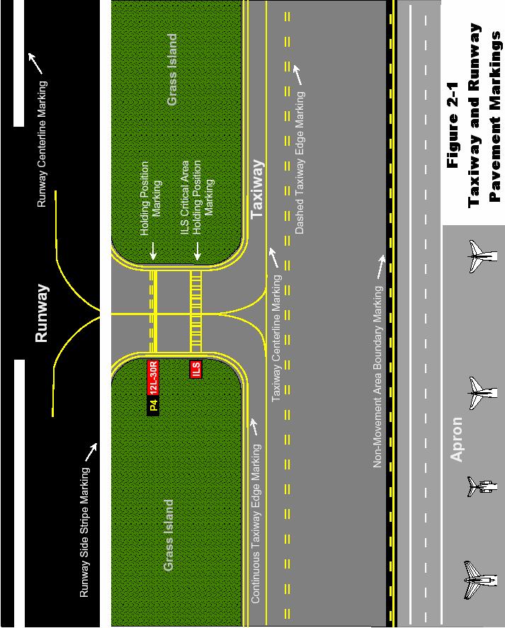
16 Section 6. PAVEMENT MARKINGS Runway and taxiway markings (paintings) are essential for the safe and efficient use of the airport. Following are the different markings for taxiways and runways. A. Taxiway Pavement Markings All taxiway-marking colors are yellow. See Figure 2 1 for examples of all taxiway markings detailed below. Taxiway Centerline Markings The taxiway centerline marking is a continuous yellow line with a minimum width of 6 inches. On a taxiway curve, the taxiway centerline marking continues from the straight portion of the taxiway at a constant distance from the outside edge of the curve. At taxiway intersections with a runway end, the taxiway centerline marking is terminated at the runway edge. For taxiways crossing a runway, the taxiway centerline marking may continue across the runway but must be interrupted for the runway markings. Enhanced taxiway centerline markings consist of a parallel line of yellow dashes on either side of the taxiway centerline. Taxiway centerlines are enhanced for 150 feet prior to a runway holding position marking. Taxiway Edge Markings Taxiway edge markings are used to delineate the edge of the taxiway. They are primarily used when the taxiway does not correspond with the edge of the pavement. There are two types of markings used depending on whether the aircraft is supposed to cross the taxiway edge; they are continuous or dashed. Continuous Markings Continuous taxiway edge markings are used to delineate the taxiway edge from the shoulder or some other contiguous paved surface not intended for use by aircraft. The markings consist of a continuous double yellow line, with each line being at least six inches in width and spaced six inches apart. Dashed Markings Dashed taxiway edge markings are used when there is an operational need to define the edge of a taxiway or taxi lane on a paved surface where the pavement next to the edge is intended for use by aircraft. The markings consist of a broken double yellow line with each line being at least six inches in width and spaced six inches apart. The lines are 15 feet in length with gaps of 25 feet. Non-Movement Area Boundary Markings Non-movement area boundary markings are used when there is a need to delineate the movement area from the non-movement area. The markings consist of two yellow lines (one solid and one dashed). The solid line is located on the non-movement area side while the dashed yellow line is located on the movement area side. 16
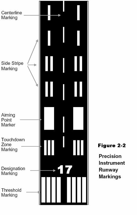
17 B. Runway Pavement Markings All runways contain markings for precision instrument approaches. Runway markings are always white. On light-colored runway pavements, outlining with a black border at least 6 inches in width can increase the contrast of the markings. See Figure 2 2 for examples of all runway pavement markings detailed below. All precision instrument runways have the following marking elements: 1. Centerline Marking 2. Designation Marking 3. Threshold Marking 4. Aiming Point Marking 5. Touchdown Zone Marking 6. Side Stripes Centerline Markings The runway centerline markings are located on the centerline of the runway and consist of a line of uniformly spaced stripes and gaps. The stripes are 120 feet in length, and the gaps are 80 feet in length. The minimum width of the stripes for a precision instrument runway is 3 feet. Designation Markings Runways are identified by numbers that indicate the nearest 10-degree increment of the azimuth when on the runway centerline. The magnetic azimuth of the runway centerline is measured clockwise from the magnetic north when viewed from the direction of approach. For example, where the magnetic azimuth is 303 degrees, the runway designation marking would be 30. When a magnetic azimuth ends in the number 5, such as 045 degrees, the runway designation can be either 4 or 5. Single digits are not preceded by a zero. Threshold Markings The runway threshold is the beginning of that portion of the runway useable for landing. The marking consists of eight longitudinal stripes of uniform dimensions arranged symmetrically about the runway centerline. The stripes are 150 feet long and 12 feet wide and are spaced 3 feet apart except for the center space, which is 16 feet. Touchdown Zone Markings Touchdown zone markings consist of groups of one, two and three rectangular bars symmetrically arranged in pairs about the runway centerline. The stripes are 75 feet long and six feet wide. These markings denote the touchdown zone of the runway, which is the first 3,000 feet of the runway beginning at the threshold. Aiming Point Markings The aiming point markings are a part of the touchdown zone markings and are located 1000 feet from the approach end of the runway. The stripes are 30 feet wide and 150 feet long. 17

18 Side Stripes Runway side stripes consist of continuous stripes located along each side of the runway to provide contrast with the surrounding terrain and/or to delineate the full strength runway pavement area. The maximum distance between the outer edges of the stripes is 200 feet. The stripes have a minimum width of 36 inches for precision instrument runways. Holding Position Markings Holding position markings consist of a painted hold line and a mandatory instruction sign. The markings are located on all surfaces that intersect a runway. The painted hold line consists of two continuous yellow lines and two dashed yellow lines, spaced 6 inches between lines and perpendicular to the taxiway centerline. These lines are also be highlighted by black lines. The solid lines of the holding position markings are always on the side where the aircraft is to hold. Holding position markings are painted at Taxiway/Runway and Runway/Runway intersections. When approaching the holding position markings from the red arrow, vehicles are required to stop and request clearance from ATCT before proceeding. When approaching the holding position markings from the green arrow, vehicles are required to continue beyond the markings. Surface Painted Holding Position Markings These are red background surface painted markings with a white inscription and are designed to supplement the signs located at the holding position. Enhanced taxiway centerline marking and surface painted holding position markings. 18
19 19
20 20
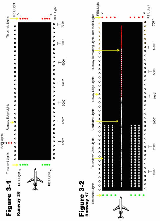
21 Section 7. MOVEMENT AREA LIGHTING Airport lighting allows aircraft to utilize an airport during periods of darkness or times of low visibility. Without lights, aircraft would basically be restricted from operating at airports except when there is sunshine and blue skies. See Figures 3-1 and 3-2. A. Taxiway Lighting Taxiway Edge Lights These lights are used to outline the edges of taxiways during periods of darkness or reduced visibility. All taxiway lights are blue and have 3 intensity settings; 3 being the highest and 1 being the lowest. B. Runway Lighting Runway End Identifier Lights (RENL) RENLs consist of two synchronized white flashing lights, one on each side of the runway threshold, which provide rapid and positive identification of the approach end of a particular runway. Runways 35, 08, and 26 all have this type of lighting at PNS. Runway Edge Lights These lights are used to outline the edges of runways during periods of darkness or reduced visibility. These light systems are classified according to the intensity or brightness that they are capable of producing. All runway lights at PNS are High Intensity Runway Lights (HIRL) with 5 intensity settings; 5 being the highest and 1 being the lowest. The runway edge lights are white except where amber lights replace the white lights on the last 2,000 feet of the runway to form a caution zone Threshold Lights These lights mark both the approach and departure ends of the runway. There are two sets of four lights that emit green light out to approaching aircraft to indicate the approach end and two sets of four lights that emit red light at the opposite end of the runway to indicate the departure end. Touchdown Zone Lights Touchdown zone lights consist of two sets of three rows of white flush mounted transverse light bars installed in the runway pavement and located symmetrically along the runway centerline normally at 100 foot intervals. The basic system extends 3,000 feet down the runway from the approach end. These lights are only found on runway 17 at PNS. Centerline Lights Centerline lights are flush mounted in the pavement along the centerline of the runway. Starting 75 feet from either end of the runway, they are spaced at 50 foot intervals the remaining length of the runway. Runway 17/35 is the only runway at PNS that has centerline lights. Each centerline light fixture has bulbs on opposite sides. The lights on one side of the fixture can only be seen when using Runway 17 and the lights on the opposite side of the fixture can only be seen when using Runway 35. Centerline lights are white, except for the Runway Remaining Lights on the last 3,000 feet of both 17 and 35 where they begin to alternate red and white. For the last 1,000 feet, these lights are all red. 21
22 22

23 Section 8. AIRPORT LIGHTING A. Airport Beacon The beacon is located on top of the Air Traffic Control Tower southwest of the intersection of the runways. The beacon is a visual navigation aid displaying alternating white and green flashes to indicate a lighted, civilian, land airport. Whenever the beacon is illuminated during daytime hours, drivers should assume that the airport is under instrument conditions and aircraft are using the Instrument Landing System (ILS). During these conditions, all drivers operating on or near the Glideslope Critical Area and Localizer Critical Area will hold short and obtain ATCT clearance before entrance into these areas. B. Obstruction Lights Obstruction lighting is used to warn pilots that a hazard exists and that caution should be used when moving in the area. Obstruction lights are red and are used during the hours of darkness and periods of limited visibility. Construction activities, holes, trenches, equipment and structures are all examples of where obstruction lights may be used. Section 9. NAVIGATION AIDS A. Instrument Landing System (ILS) Glideslope The glideslope is a part of the ILS Navigation System that provides vertical guidance for aircraft during approach and landing. Runway 17 at PNS has a glideslope and the glideslope antenna for Runway 17 is located on the left side of the runway. Glideslope Critical Area A rectangular tract surrounding the glideslope antenna should be graded and kept free and clear of objects that could interrupt the signal. This area is outlined with signs labeled CRITICAL AREA and all vehicles should remain clear of these areas unless coordinated with ATCT. All vehicles must contact FAA Ground Control and obtain permission before entering the Critical Area whenever the runway for that glideslope is active and aircraft are operating under instrument conditions. For example: Runway 17 is active and aircraft are operating under instrument conditions as shown in the diagram on the left. Prior to entering the Critical Area identified in red, vehicles must coordinate with ATCT. 23
24 Localizer The localizer is another part of the ILS Navigation System and provides lateral guidance to aircraft on an approach to the runway. Runway 17 at PNS has a localizer and it is located on the extended centerline of the runway, 1,000 feet beyond the departure end. Runway 26 will have a localizer beyond the departure end. See Figure 3-4. Localizer Critical Area The localizer antenna requires a key-hole shaped cleared area which surrounds it and extends towards and overlies a portion of the runway. This area should be kept free and clear of all objects that could possibly affect the localizer signal. No vehicles should enter this area unless first coordinated with ATCT. All vehicles must contact FAA Ground Control and obtain permission before entering the Critical Area whenever the runway for that localizer is active and aircraft are operating under instrument conditions. For example: Runway 17 is active and aircraft are operating under instrument conditions as shown in the diagram on the previous page. Prior to entering the Critical Area identified in red, vehicles must coordinate with ATCT. Airport Surveillance Radar (ASR) This radar is used by the air traffic control tower and provides the position of aircraft in terms of azimuth and range data. It does not provide elevation data and is designed for range coverage up to 60 nautical miles. See Figure 3-5. ASR Safety Area Due to the nature of this equipment, all vehicles should maintain as great a distance as possible when operating in the vicinity of the Airport Surveillance Radar (ASR). The ASR site is located northeast of the intersection of the runways. Runway Visual Range (RVR) This is an instrumentally derived value representing the distance a pilot will see down the runway from the touchdown, midpoint or rollout portions of the runway. It is based on the sighting of either high intensity runway lights or the visual contrast of other targets, whichever yields the greatest visual range. The equipment that enables the RVR value to be obtained consists of a projector and receiver. There is one RVR site at PNS located between Runway 17/35 and Taxiway A, just south of Taxiway A5 feeder. See Figure 3-3. Wind Socks These are located along the runways and are lighted during periods of darkness or reduced visibility. There are four wind socks at PNS, near the approach ends of 08, 26, 35 and the center of the field. The wind socks are made of flexible fabric and move freely when subjected to air movement. The wind socks indicate the wind direction and wind force by noting which way the sock is pointing and whether the sock hangs limply or is extended. The sock points to the direction that the wind is blowing and is designed to be fully extended with a wind of 15 knots. Variable winds will make the sock swing back and forth, while wind gusts will cause it to swing up and down. See Figure
25 Figure 3-3: Runway Visual Range Figure 3-4: Localizer Figure 3-5: Airport Surveillance Radar (ASR) Figure 3-6: Wind sock 25
26 Section 10. COMMUNICATIONS In the Air Traffic Control System, radio communication is a vital link between controllers, pilots and ground vehicle operators. Proper radio communication is one of the basics for safety, orderliness and efficiency in this system. Comprehending or understanding directions from the controller and being certain that the controller understands or comprehends requests and responses are the basics for good radio communications. This process is ensured through a system of checks and balances. Before making a transmission, there are several things to do. The first thing is LISTEN. Listen to the radio frequency before transmitting. If there is a conversation in progress, wait until it is completed before starting your transmission. Conversations in progress could range from a controller issuing instructions to a pilot for taxiing, to a maintenance vehicle making a request to cross a runway. The next thing to consider before transmitting is WHAT YOU WANT TO SAY before you start your transmission. If you know exactly what you want to say and how you will say it, your transmission will be more concise and understandable. When you have been instructed by a controller to proceed with something, you should acknowledge that you have received and understood the instructions by repeating the instructions and stating your call sign. If for some reason you don t understand what the controller has told you, or you think that the controller does not understand what you have said, STOP! Either confirm what the controller has told you, or clarify to the controller what you are requesting. You are better off to question something and fully understand it, instead of proceeding forward. When transmitting, the microphone should be close to your lips but not touching them. After you key the mike, pause for a half-second before making your transmission. This will ensure that your first word is transmitted. When speaking, talk in a normal conversational tone and try not to yell, slur your words, or talk too fast. When attempting to contact the tower, your transmission must contain certain information and be in a specific format. The following information should be included in your transmission: 1. The name of the facility being called. 2. Your call sign. 3. Your location. 4. Your request or message. 26
27 An example transmission might sound like the following: Pensacola Ground, Ops 1 on Bravo to cross runway one seven. After you have made your transmission, wait a short while before attempting it again. Many times, the controllers have heard you and are attempting to either locate your position or are coordinating your request with another controller before giving you a reply. After approximately 30 seconds, if you have not heard a reply, repeat your transmission. If you still don t get a reply, check that your radio equipment is turned on and that you are transmitting on the correct frequency. While waiting for a reply or checking your equipment, always be sure to keep an eye on the tower for light gun signals that may be directed toward you. Phonetic Alphabet In the aviation community, letters, numbers and time are used quite often and can be both confusing and misinterpreted. To prevent this confusion from occurring, the International Civil Aviation Organization (ICAO) established an alphabet that allows words to replace letters. These words were chosen for their unique sound, thereby reducing the chance of confusion with another letter. This alphabet is commonly known as the ICAO International Phonetic Alphabet. ICAO International Phonetic Alphabet A Alpha H Hotel O Oscar V Victor B Bravo I India P Papa W Whiskey C Charlie J Juliet Q Quebec X X Ray D Delta K Kilo R Romeo Y Yankee E Echo L Lima S Sierra Z Zulu F Foxtrot M Mike T Tango G Golf N November U Uniform Numbers Single digit numbers are pronounced as they normally sound except for the number 9. This is pronounced Niner in radio transmissions. The reason for this is that the number nine sounds similar to the number five. Numbers of two or more digits are generally spoken as a series of single digits, with the exception of round numbers, such as hundreds or thousands. The following are examples of how numbers should be pronounced during radio transmissions: 27
28 25 Two Five 332 Three Three Two 600 Six Hundred 0900 Zero Niner Hundred 29,600 Two Niner Thousand Six Hundred Radio Frequencies are also spoken as separate numbers. For example, is spoken as One Two One Point Niner. Another example is 119.9, One One Niner Point Niner. Time is expressed as minutes after the hour when the hour is understood. The time may be stated as Three Niner for 39 minutes after the hour or as Five Eight for 58 minutes after the hour. Time Another significant standard in the field of aviation is the use of the 24-hour clock in conjunction with Universal Coordinated Time, (UTC). The 24-hour clock eliminates the a.m. and p.m. designators that exist with the standard 12-hour clock. UTC, (also called ZULU time) puts all aviation communications on the same worldwide time standard. This avoids any possible confusion when crossing time zones. With the 24-hour clock, the hours of the day are numbered consecutively, as 0000 (Midnight), 0100, 0200, to 1200 (Noon). The afternoon hours continue as 1300 (1:00 p.m.), 1400, 1500, and on to Midnight can be expressed as either 0000 or Time is spoken as in the following examples: 0823 Zero Eight Two Three 8:23 a.m One Four Five Six 2:56 p.m Two Three Five Niner 11:59 p.m. Time can be converted to UTC (Zulu) by using the table below. TIME ZONE TO GET UTC DAYLIGHT SAVINGS Eastern Standard Time Add 5 hours Add 4 hours Central Standard Time Add 6 hours Add 5 hours Mountain Standard Time Radio Checks Add 7 hours Add 6 hours Pacific Standard Time Add 8 hours Add 7 hours 28
29 Radio Checks Occasionally, it is desirable to ask a facility to evaluate the strength and quality of your transmissions. Simply say, Radio Check, please. A reply of Loud and Clear means strength and quality are good. Weak and Clear means strength is poor, but quality is good. Traffic Control Light Gun Signals In the event that you lose radio communications with the ATCT, the tower has a high powered light gun that emits colored light beams. A vehicle operator should position his/her vehicle such that the headlights are facing the tower. The headlights should then be repeatedly turned on and off to attempt to get the attention of the controller. Once the ATCT is aware of the vehicle, they will advise the operator of what to do with the light gun signals. These procedures should be used in EMERGENCY situations only. These high intensity beams all have meanings and all individuals that operate on a movement area must know them. The following table shows the light gun signals and their meanings: COLOR AND TYPE OF SIGNAL Steady Green MOVEMENT OF VEHICLES Cleared to cross, proceed Steady Red STOP Flashing Red Clear the Taxiway or Runway Flashing White Return to starting point on Airport Alternating Red and Green Exercise extreme caution 29
30 Commonly Used Radio Phrases Abeam Acknowledge Affirmative Correction Go Ahead How Do You Hear Me I Say Again Negative Out Read Back Roger Say Again Speak Slower Stand By That Is Correct Out from, or across from Let me know that you have received and understood this message Yes An error has been made in this transmission. The correct version is Proceed with your message Self-explanatory Self-explanatory That is not correct. No. This conversation is ended and no response is needed Repeat all of this message back to me I have received all of your last transmission (This word is used to acknowledge receipt and shall not be used for other purposes.) Repeat your last transmission Self-explanatory If used by itself it means, I must pause for a few seconds. If the pause lasts longer than a few seconds, the transmission should be concluded and contact should be re-established later. Self-explanatory 30
 / Common Traffic Advisory Frequency (CTAF) 121.")
31 ATCT Frequencies Used at PNS It is very important to understand that the ATCT at PNS utilizes several different frequencies. Following are the most commonly used frequencies by both aircraft and vehicles: Ground Control Local Control (Tower) / Common Traffic Advisory Frequency (CTAF) ATIS (Automated Terminal Information Service) Ground Control frequency is used by aircraft when operating on the ramps and taxiways. Ground Control frequency is used by vehicles when operating on taxiways is the ground control frequency. Local Control frequencies are used by aircraft requesting clearance to takeoff or land and by vehicles when it becomes necessary to proceed on an open runway (ex. inspections, maintenance operations, or retrieving FOD) is the local control frequency. It is also the Common Traffic Advisory Frequency (CTAF) during the hours that the ATCT is closed. ATIS is a continuous broadcast of current weather conditions and NOTAM information at the airport. This frequency provides necessary information to aircraft while reducing congestion on other frequencies. Thank you for your commitment to safe driving at Pensacola International Airport! 31
Driving Training Class. Presented by: Lancaster Airport Authority
 Driving Training Class Presented by: Lancaster Airport Authority Driving is a Privilege Driving on the airport, airport apron and ramps is a privilege and can be revoked at anytime for any reason. Violations
MCAS CHERRY POINT. Basic Airfield Vehicle Operator Course (AVOC)
") MCAS CHERRY POINT Basic Airfield Vehicle Operator Course (AVOC) REFERENCES 1) FAA Handbook 7110.65 (ATC) 2) NAVAIR 00-80T-114 (ATC NATOPS) 3) MCO 1500.19 (Safety Program) 4) AirStaO P 3710.5 (AOM) 5) ATCFacO
MCAS CHERRY POINT Basic Airfield Vehicle Operator Course (AVOC) REFERENCES 1) FAA Handbook 7110.65 (ATC) 2) NAVAIR 00-80T-114 (ATC NATOPS) 3) MCO 1500.19 (Safety Program) 4) AirStaO P 3710.5 (AOM) 5) ATCFacO
LANCASTER AIRPORT DRIVER TRAINING PROGRAM
 LANCASTER AIRPORT DRIVER TRAINING PROGRAM INTRODUCTION 1. Airfield Driving Basics 2. Movement / Non-Movement Area 3. Airfield Signs, Markings & Lighting 4. Airfield Communications 5. Aviation Phonetics
CHICO MUNICIPAL AIRPORT NON-MOVEMENT AREA DRIVER TRAINING PROGRAM
 CHICO MUNICIPAL AIRPORT NON-MOVEMENT AREA DRIVER TRAINING PROGRAM Introduction In an effort to provide the safest and most efficient operating environment for tenants and users of the Chico Municipal Airport
Location, Identity, Specific Location, Intention, Location Again
 I. PEDESTRIAN AND GROUND VEHICLE RULES AND INFORMATION The Sanford Seacoast Regional Airport (SFM) is a nontowered airport, meaning it has no air traffic control tower. Any vehicle authorized to operate
Brunswick Executive Airport. Airport Safety Program
 Brunswick Executive Airport Airport Safety Program Why Runway Incursions FY 14 FY 13 FY 12 FY 11 1 st Quarter 298 273 226 215 2 nd Quarter 258 287 267 246 3 rd Quarter 359 328 352 257 4 th Quarter 349
ICAO Standards. Airfield Information Signs. ICAO Annex 14, 4th Edition Aerodrome Design and Operations
 ICAO Standards Airfield Information Signs ICAO Annex 14, 4th Edition Aerodrome Design and Operations Federal Aviation Administration U.S. Department of Transportation February 2004 ICAO Standards This
ICAO Recommended Airport Signs, Runway And Taxiway Markings. COPYRIGHT JEPPESEN SANDERSON, INC., ALL RIGHTS RESERVED. Revision Date:
 ICAO Recommended Airport Signs, Runway And Taxiway Markings Revision Date: 20051230 MANDATORY INSTRUCTION SIGNS A mandatory instruction sign identifies a location beyond which an aircraft taxiing shall
7/1/2014. Class II Driver s License Information and Study Guide
 7/1/2014 Class II Driver s License Information and Study Guide TABLE OF CONTENTS I. INTRODUCTION Purpose... 1 General Requirements... 1 Policy Statement... 1 Authority... 2 Procedures For Obtaining an
LANCASTER AIRPORT AIRPORT UTILIZATION BY VEHICLE OPERATORS
 LANCASTER AIRPORT AIRPORT UTILIZATION BY VEHICLE OPERATORS Revised: October 25, 1995 TABLE OF CONTENTS Airport Utilization by Vehicle Operators... Page 1 Communications Ideas and Practices... Page 2 Phonetic
Runway and Taxiway Marking
 Lecture-38 10CV63 TE-II Runway and Taxiway Marking In order to aid pilots in guiding the aircraft on runways and taxiways, pavements are marked with lines and numbers. These markings are of benefit primarily
SURFACE MOVEMENT GUIDANCE AND CONTROL SYSTEM PLAN. Los Angeles International Airport
 SURFACE MOVEMENT GUIDANCE AND CONTROL SYSTEM PLAN Los Angeles International Airport Surface Movement Guidance and Control System (SMGCS) Plan The SMGCS Plan for Los Angeles International Airport (LAX)
AERODROME MARKINGS AND SIGNALIZATION
 1. Introduction AERODROME MARKINGS AND SIGNALIZATION This article will present the main aerodrome markings and signalization on runways and taxiways. 2. Runway Markings This chapter will show the runway
MOTOR VEHICLE OPERATING PERMIT PROGRAM (MVOP)
") MOTOR VEHICLE OPERATING PERMIT PROGRAM (MVOP) STUDY GUIDE PRODUCED BY VAN NUYS AIRPORT OPERATIONS JANUARY 2018 INTENTIONALLY LEFT BLANK Introduction In an effort to provide the safest and most efficient
MOTOR VEHICLE OPERATING PERMIT PROGRAM (MVOP) STUDY GUIDE PRODUCED BY VAN NUYS AIRPORT OPERATIONS JANUARY 2018 INTENTIONALLY LEFT BLANK Introduction In an effort to provide the safest and most efficient
 Telephone No. 2:4622495 Telegraphic Address: Commercial : AIRCIVIL NEW DELHI Aeronautical : VIDDYAYX E Mail: dri@dgca.nic.in Fax : 01124629221 GOVERNMENT OF INDIA AERONAUTICAL INFORMATION SERVICES DIRECTOR
RUNWAY INCURSION PREVENTION PROGRAM ICAO NAM/CAR/SAM RUNWAY SAFETY/INCURSION CONFERENCE Mexico City, 22 to 25 October 2002
 RUNWAY INCURSION PREVENTION PROGRAM ICAO NAM/CAR/SAM RUNWAY SAFETY/INCURSION CONFERENCE Mexico City, 22 to 25 October 2002 I n t e r n a t i o n a l A i r T r a n s p o r t A s s o c i a t I o n I A T
a. Aeronautical charts DID THIS IN LESSON 2
 AIRMAN CERTIFICATION STANDARDS: REMOTE PILOT SMALL: You will know and be able to explain in writing or oral form the below tasks regarding AIRPORT OPERATIONS Task References Objective Task B. Airport Operations
Airport Ground Vehicle Operations Program
 Airport Ground Vehicle Operations Program Morristown Municipal Airport Operated by: August 12, 2010 Table of Contents SECTION 1 DEFINITIONS 3 SECTION 2 - AMA DRIVING RULES AND REGULATIONS 6 2.1 AUTHORITY
Two s Too Many BY MARK LACAGNINA
 BY MARK LACAGNINA Two s Too Many Angled taxiways limiting the pilots view of the runway, clearances issued and read back hastily and incorrectly, and crossed radio transmissions 1 were among the common
MCAS CHERRY POINT. Basic Airfield Vehicle Operator Course (AVOC)
") MCAS CHERRY POINT Basic Airfield Vehicle Operator Course (AVOC) REFERENCES 1) FAA Handbook 7110.65 2) NAVAIR 00-80T-114 3) MCO 1500.19 4) AirStaO P 3710.5 5) ATCFacO P3722.1 PURPOSE The purpose of the
MCAS CHERRY POINT Basic Airfield Vehicle Operator Course (AVOC) REFERENCES 1) FAA Handbook 7110.65 2) NAVAIR 00-80T-114 3) MCO 1500.19 4) AirStaO P 3710.5 5) ATCFacO P3722.1 PURPOSE The purpose of the
AIRPORTS There are two types of airport environments: controlled and uncontrolled. A controlled airport has an operating control tower, staffed by
 AIRPORTS There are two types of airport environments: controlled and uncontrolled. A controlled airport has an operating control tower, staffed by either Federal or privately-contracted air traffic controllers.
TANZANIA CIVIL AVIATION AUTHORITY SAFETY REGULATION CHECKLIST FOR INSPECTION OF SURFACE MOVEMENT GUIDANCE CONTROL SYSTEM (SMGCS)
") Page 1 of 11 AERODROME NAME: ICAO REFERENCE CODE: TRAFFIC DENSITY CLASS: (see Note 3) VISIBILITY CONDITION: (see Note 3) AERODROME INSPECTOR: DATE: S/N ICAO A SURFACE MOVEMENT GUIDANCE CONTROL SYSTEM 1
Page 1 of 11 AERODROME NAME: ICAO REFERENCE CODE: TRAFFIC DENSITY CLASS: (see Note 3) VISIBILITY CONDITION: (see Note 3) AERODROME INSPECTOR: DATE: S/N ICAO A SURFACE MOVEMENT GUIDANCE CONTROL SYSTEM 1
Chapter The All-new, World-class Denver International Airport Identify Describe Know Describe Describe
 Chapter 10 The aerospace subject is very large and diverse. As seen in previous chapters, there are many subject areas. So far you have learned about history, weather, space and aerodynamics. Now you will
Source: Chippewa Valley Regional Airport ASOS, Period of Record
 Chapter 1 Inventory Runway wind coverage is the percentage of time a runway can be used without exceeding allowable crosswind velocities. Allowable crosswind velocities vary depending on aircraft size
II.B. Runway Incursion Avoidance
 References: AC 91-73 Objectives Key Elements Elements Schedule Equipment IP s Actions SP s Actions Completion Standards The student should develop knowledge of the elements related to proper incursion
RUNWAY SAFETY. An airside driver s guide to
 RUNWAY SAFETY An airside driver s guide to 6th edition - October 2016 INTRODUCTION Traffic levels rise, airports expand, and you, as an airside driver are expected to understand how to safely operate
Rules and Regulations
 APPENDIX 1 LOW-VISABILITY OPERATIONS/SURFACE MOVEMENT GUIDANCE AND CONTROL SYSTEM (LVO/SMGCS) PLAN TABLE OF CONTENTS TITLE PAGE 1.0 INTRODUCTION 2 2.0 DEFINITIONS 3 3.0 FACILITIES, SERVICES AND EQUIPMENT
Appendix D AIRSIDE VEHICLE DRIVING BEST PRACTICES
 Appendix D AIRSIDE VEHICLE DRIVING BEST PRACTICES Note. This guidance is a compilation of material drawn from many sources including ICAO, IATA, ACI and a number of aerodromes that already operate vehicle
USE OF RADAR IN THE APPROACH CONTROL SERVICE
 USE OF RADAR IN THE APPROACH CONTROL SERVICE 1. Introduction The indications presented on the ATS surveillance system named radar may be used to perform the aerodrome, approach and en-route control service:
DALLAS/FORT WORTH INTERNATIONAL AIRPORT SURFACE MOVEMENT GUIDANCE AND CONTROL SYSTEM SMGCS PLAN FOR ARRIVAL RUNWAYS 17L-35R, 17C-35C, AND 18R
 DALLAS/FORT WORTH INTERNATIONAL AIRPORT SURFACE MOVEMENT GUIDANCE AND CONTROL SYEM SMGCS PLAN FOR ARRIVAL RUNWAYS 7L-35R, 7C-35C, AND 8R DEPARTURE RUNWAYS 7R-35L AND 8L-36R Published September 30, 20 (Reviewed
DRIVER TRAINING MANUAL Movement Area
 DRIVER TRAINING MANUAL Movement Area Version 1.2 FWACAA Driver Training Manual - Movement Page 1 Table of Contents INTRODUCTION... 4 1. Applicability... 5 2. Definitions... 5 3. Severability... 7 4. Violation
GRANDE PRAIRIE AIRPORT. Reduced Visibility Operations Plan
 GRANDE PRAIRIE AIRPORT Reduced Visibility Operations Plan Amended November 8, 2017 Distribution List: (Updates to the Reduced Visibility Operations Plan will be circulated to this list.) Name and Title
Runway Incursions 3 Markings
 Session Visual Aids Runway Incursions 3 Markings 3.12.2 A runway-holding position shall be established: a) on the taxiway, at the intersection of a taxiway and a runway; and b) at an intersection of a
National Transportation Safety Board Washington, D.C
 E PLURIBUS UNUM NATIONAL TRA SAFE T Y N S PORTATION B OAR D National Transportation Safety Board Washington, D.C. 20594 Safety Recommendation Date: June 25, 2004 In reply refer to: A-04-48 through -50
Ref. AIM Para AOPA Air Safety Foundation Supported by the FAA Ref. AIM Para Supported by the FAA
 ILS Critical Area Holding Position Sign: ATC may hold you at this sign, on a taxiway, when the instrument landing system is being used at the airport. Aircraft taxiing beyond this point may interfere with
Runway Crossings at Brisbane International Airport
 Runway Crossings at Brisbane International Airport All instructions to cross runways will be issued by Ground on 121.7 MHz All runway crossings require a specific CROSSING clearance. Runway Crossing Requirements
WFC HANGER TALK SERIES This Event - Mean what you say : say what you mean Control Tower Procedures Prep for Simulator Exercise
 Challenge for the Simulator portion of the event get out of the plane and into the Control Tower BACKGROUND INFORMATION RUNWAY SELECTION Assign the operationally suitable runway most nearly aligned into
Airport Operations. Chapter 14. Introduction. Airport Categories
 Chapter 14 Airport Operations Introduction Each time a pilot operates an aircraft, the flight normally begins and ends at an airport. An airport may be a small sod field or a large complex utilized by
VI.C. Airport, Runway and Taxiway Signs, Markings, and Lighting
 References: FAA-H-8083-23; FAA-H-8083-25; AIM; AC 150/5340-1; AC 150/5340-18 Objectives Key Elements Elements Schedule Equipment IP s Actions SP s Actions Completion Standards The student should develop
Airport Ground Vehicle Operations Program. Airport Ground Vehicle Operations Program - 1 -
 Airport Ground Vehicle Operations Program - 1 - Introduction Why is a Vehicle Operations Program needed at our airport? It is important for the Boulder City Municipal Airport (BVU) to develop a Ground
Navigation - Runways. Chap 2, Nolan
 Navigation - Runways Chap 2, Nolan 1 Runways Runways numbered to correspond to magnetic bearing Runway 27 has magnetic bearing 270 degrees Active Runway selected for headwind greater than 5 knots When
GTR Movement Area Drivers Training Manual
 GTR Movement Area Drivers Training Manual TABLE OF CONTENTS: Introduction.2 Basic parts of an airport.2 Non-Movement Area...3 Movement Areas. 4 Aircraft Operations 7 Control Tower Operations. 9 Uncontrolled
Runway Excursion 2018 projects ALTA 2018
 Runway Excursion 2018 projects ALTA 2018 Mayor cities workshops Pilots and controller's simulator section visit Proposed cities Miami, Mexico City, El Salvador, San Jose, Panama City, Bogota, Lima, Santiago,
DRIVER TRAINING MANUAL Non-Movement Area
 DRIVER TRAINING MANUAL Non-Movement Area Version 1.2 FWACAA Driver Training Manual Non-Movement Page 1 Table of Contents INTRODUCTION... 3 1. Applicability... 4 2. Definitions... 4 3. Severability... 6
Central Nebraska Regional Airport Ground Operations Drivers Training
 Central Nebraska Regional Airport Ground Operations Drivers Training Updated 3/2014 The airport surface environment is a complex and dynamic place, the dimensions of which are bounded, not only by the
Page 1 of 8 Document : V1.1
 VFR COMMUNICATION, HOW TO DO THIS Learning Goals VFR R/T TRAINING General ATC or Air Traffic Control is the contact between you the pilot and the controllers on the ground. It is important that you can
SECTION 1 AOA Movement Ground Vehicle Operation Rules & Regulations SECTION 2 Driver Training Manual
 SECTION 1 AOA Movement Ground Vehicle Operation Rules & Regulations SECTION 2 Driver Training Manual LFSRA FORM 003 1 Section 1. Airport Driving Rules and Regulations 1.1. Authority for Implementation
A PILOT S GUIDE To understanding ATC operations at Lancaster Airport
 A PILOT S GUIDE To understanding ATC operations at Lancaster Airport - 1 - Welcome to the Lancaster Airport (This material shall be used for informational purposes only) The Air Traffic Controllers at
APPENDIX D FEDERAL AVIATION REGULATIONS, PART 77
 APPENDIX D FEDERAL AVIATION REGULATIONS, PART 77 Subparts A through C PART 77 - OBJECTS AFFECTING NAVIGABLE AIRSPACE Subpart A General 77.1 Scope. 77.2 Definition of terms. 77.3 Standards. 77.5 Kinds of
VEHICLE OPERATORS TRAINING MANUAL (PART 1: NON-MOVEMENT AREA)
") VEHICLE OPERATORS TRAINING MANUAL (PART 1: NON-MOVEMENT AREA) TABLE OF CONTENTS PART 1: NON-MOVEMENT AREA Section 1: Airport Driving Rules and Regulations... 2 Section 2: Driving on the Non-Movement Areas...
VEHICLE OPERATORS TRAINING MANUAL (PART 1: NON-MOVEMENT AREA) TABLE OF CONTENTS PART 1: NON-MOVEMENT AREA Section 1: Airport Driving Rules and Regulations... 2 Section 2: Driving on the Non-Movement Areas...
DRIVING OF VEHICLES ON THE MOVEMENT AREA - AIRPORT VEHICLE OPERATOR PERMIT (AVOP)
") Driving of Vehicles on the Movement Area Airport Vehicle Operator Permit (AVOP) (NAME OF THE COUNTRY, CAA LOGO ETC.) AIRPORT DIRECTIVE NO: SUBJECT: DRIVING OF VEHICLES ON THE MOVEMENT AREA - AIRPORT VEHICLE
Driving of Vehicles on the Movement Area Airport Vehicle Operator Permit (AVOP) (NAME OF THE COUNTRY, CAA LOGO ETC.) AIRPORT DIRECTIVE NO: SUBJECT: DRIVING OF VEHICLES ON THE MOVEMENT AREA - AIRPORT VEHICLE
1.1.3 Taxiways. Figure 1-15: Taxiway Data. DRAFT Inventory TYPICAL PAVEMENT CROSS-SECTION LIGHTING TYPE LENGTH (FEET) WIDTH (FEET) LIGHTING CONDITION
 WIDTH (FEET) LIGHTING CONDITION") 1.1.3 Taxiways EWN has an extensive network of taxiways and taxilanes connecting the terminal, air cargo, and general aviation areas with the runways as listed in Figure 1-15. A 50-foot wide parallel taxiway
1.1.3 Taxiways EWN has an extensive network of taxiways and taxilanes connecting the terminal, air cargo, and general aviation areas with the runways as listed in Figure 1-15. A 50-foot wide parallel taxiway
AIRSIDE VEHICLE OPERATORS PERMIT PROGRAM AVOP "D" TRAFFIC DIRECTIVES
 AIRSIDE VEHICLE OPERATORS PERMIT PROGRAM AVOP "D" TRAFFIC DIRECTIVES 1 AIRSIDE VEHICLE OPERATORS PERMIT PROGRAM (AVOP) INTRODUCTION The Airside of an airport is a specialized working environment governed
print materials visit information on free live seminars, online courses, and
 The AOPA Air Safety Foundation is dedicated to making flying easier and safer for general aviation pilots. For information on free live seminars, online courses, and print materials visit. ILS Critical
VFR PHRASEOLOGY. The word IMMEDIATELY should only be used when immediate action is required for safety reasons.
 VFR PHRASEOLOGY 1. Introduction 1.1. What is phraseology? The phraseology is the way to communicate between the pilot and air traffic controller. This way is stereotyped and you shall not invent new words.
Section 32 TABLE OF CONTENTS Airfield and Aircraft Operations. 32.A General B Aircraft
 Section 32 TABLE OF CONTENTS Airfield and Aircraft Operations Section: Page 32.A General... 32-1 32.B Aircraft... 32-4 32-i THIS PAGE INTENTIONALLY LEFT BLANK 32-i SECTION 32 Airfield and Aircraft Operations
Ground Vehicle Operations Training Manual
 Ground Vehicle Operations Training Manual GVOTM REV 1 JUNE 2016 TABLE OF CONTENTS Section 1 Airport Driving Rules and Regulations.. Page 2 Section 2 Driving on the Non-Movement Areas Page 7 Section 3 Driving
From: Commanding Officer, Naval Air Station Pensacola. Subj: NAVAL AIR STATION PENSACOLA CLOSED CONTROL TOWER AIRFIELD OPERATIONS
 DEPARTMENT OF THE NAVY COMMANDING OFFICER NAS PENSACOLA 150 HASE ROAD STE-A PENSACOLA, FLORIDA 32508-1051 NAVAL AIR STATION PENSACOLA INSTRUCTION 3710.1 NASPCOLAINST 3710.1 N32 From: Commanding Officer,
RADIO COMMUNICATIONS AND ATC LIGHT SIGNALS
 RADIO COMMUICATIOS AD ATC LIGHT SIGALS VI - A ITRODUCTIO RADIO LICESE RADIO EQUIPMET PHRASEOLOGY LOST COMMUICATIO Receiver Transmitter Both Departure - Operating in and out of a controlled airport, as
LOW VISIBILITY OPERATION
 1. Introduction LOW VISIBILITY OPERATION Low visibility procedures exist to support low visibility operations at aerodromes. Low visibility procedures (LVP) means procedures applied at an aerodrome for
Local Airport Traffic Directives. D and D/A. Airside Vehicle Operators Permit
 Local Airport Traffic Directives D and D/A Airside Vehicle Operators Permit Revised December 2017 Table of Contents INTRODUCTION... 4 AIRPORT TRAFFIC DIRECTIVES... 5 DEFINITIONS... 6 AIRSIDE VEHICLE OPERATORS
STANDARD OPERATING PROCEDURES TACTICAL OPERATIONS b AIRCRAFT INCIDENTS AND ACCIDENTS EFFECTIVE: OCTOBER 2007
 STANDARD OPERATING PROCEDURES TACTICAL OPERATIONS 202.15b AIRCRAFT INCIDENTS AND ACCIDENTS EFFECTIVE: OCTOBER 2007 AIRCRAFT INCIDENTS AND ACCIDENTS Goals 1. To familiarize with Airport Index 2. To familiarize
Andy s Guide for Talking on the Radios
 The Basics Andy s Guide for Talking on the Radios The radios are used to both get and transmit information to/from external sources or agencies. Talking on the radios is really not difficult; but unlike
ORDINANCE NO. _2013-
 ORDINANCE NO. _2013- AN ORDINANCE OF THE TOWNSHIP OF CONEWAGO, DAUPHIN COUNTY, PENNSYLVANIA, PROVIDING FOR AIRPORT ZONING REGULATIONS WITHIN THE AIRPORT ZONING OVERLAY DISTRICT CREATED BY THIS ORDINANCE
Table of Contents. Introduction Airport Basics Security Vehicle Requirements / Operating Rules... 13
 Table of Contents Introduction... 3 Airport Basics... 4 Definitions... 4 Non-movement Area... 6 Movement Area... 6 Security... 12 Escorting... 13 Vehicle Requirements / Operating Rules... 13 Working on
Memorandum Date: January 15, 2019
 Memorandum Date: January 15, 2019 From: To: Robert L. Wagner, Air Traffic Manager, Pontiac ATCT Oakland County International Airport Subject: General Pilot information and Best Practices HOURS OF OPERATION
Ground Vehicle Operations Training READING REGIONAL AIRPORT
 Ground Vehicle Operations Training READING REGIONAL AIRPORT October 22, 2014 Airport Operations Area (AOA) Movement Areas Non-Movement Areas Non-Movement Area Markings Never cross solid line with out ATC
Low Visibility Operations
 Airside Operational Instruction 21 Uncontrolled when printed Page 0 of 7 1 LOW VISIBILITY OPERATIONS Policy East Midlands Airport (EMA) is committed to providing facilities and procedures to enable aircraft
INTRODUCTION TO THE SAFE PROGRAM
 January 2016 Page 1 INTRODUCTION TO THE SAFE PROGRAM Los Angeles World Airports (LAWA) is committed to providing the airport community with a safe and secure workplace. This document describes the purpose
INTERNATIONAL VIRTUAL AVIATION ORGANISATION CANADIAN AIR TRAFFIC CONTROL PHRASEOLOGY ATC OPERATIONS DECEMBER 2016 BY: MATHIEU LAFLAMME
 INTERNATIONAL VIRTUAL AVIATION ORGANISATION CANADIAN AIR TRAFFIC CONTROL PHRASEOLOGY ATC OPERATIONS DECEMBER 2016!1 GENERAL Proper use of phraseology is one of the most important thing in aviation and
APPLICANTS FOR AIRSIDE VEHICLE OPERATOR S PERMITS: INFORMATION
 APPLICANTS FOR AIRSIDE VEHICLE OPERATOR S PERMITS: INFORMATION These directives provide the approved protocols for the operation of vehicles and conduct of persons on the airfield at Halifax Stanfield
SECTION 32. Airfield and Aircraft Operations
 SECTION 32 Airfield and Aircraft Operations 32.A Airfields General. 32.A.01 The following safety requirements shall be in addition to the airfield's safety requirements. When an airfield has safety requirements
Session Best Practices Amendments From Annex14, Volume I Annex 15. Runway Incursions Runway Excursions
 Session Best Practices Amendments From Annex14, Volume I Annex 15 Runway Incursions Runway Excursions Annex 15 AIP - Member States Report: Installation of ARRESTOR SYSTEMS Location - Runway End Industry
Chapter 16. Airports Authority of India Manual of Air Traffic Services Part RESPONSIBILITY IN REGARD TO MILITARY TRAFFIC
 Chapter 16 16.1 RESPONSIBILITY IN REGARD TO MILITARY TRAFFIC 16.1.1 It is recognized that some military aeronautical operations necessitate non-compliance with certain air traffic procedures. In order
GENERAL INFORMATION Aircraft #1 Aircraft #2
 GENERAL INFORMATION Identification number: 2007075 Classification: Serious incident Date and time 1 of the 2 August 2007, 10.12 hours occurrence: Location of occurrence: Maastricht control zone Aircraft
TRAFFIC CONTROL DEVICES MANUAL FOR WORK ZONES
 TRAFFIC CONTROL DEVICES MANUAL FOR WORK ZONES SUMMARY Work zone activities often create conditions on the travelled way that are hazardous particularly at night when the ability of motorists to see is
PHRASEOLOGY COMMON MISTAKES
 1. How to read this manual PHRASEOLOGY COMMON MISTAKES This document is not a usual document that teaches only what to do, but this document will present the usual mistakes that every member can hear on
TUCSON INTERNATIONAL AIRPORT (TUS) DISABLED AIRCRAFT RECOVERY PLAN Section TABLE OF CONTENTS Page
 DISABLED AIRCRAFT RECOVERY PLAN Section TABLE OF CONTENTS Page") TUCSON INTERNATIONAL AIRPORT (TUS) DISABLED AIRCRAFT RECOVERY PLAN Section TABLE OF CONTENTS Page 1.0 Disabled Aircraft Recovery Plan Overview 4 1.1 Overview 4 2.0 Aircraft Incident/Accidents 6 3.0 TAA
TUCSON INTERNATIONAL AIRPORT (TUS) DISABLED AIRCRAFT RECOVERY PLAN Section TABLE OF CONTENTS Page 1.0 Disabled Aircraft Recovery Plan Overview 4 1.1 Overview 4 2.0 Aircraft Incident/Accidents 6 3.0 TAA
TABLE OF CONTENTS 1.0 INTRODUCTION...
 Advisory Circular Subject: Publication of the Level of Service with Respect to Departure Below RVR 2600 (½ Statute Mile) Issuing Office: Civil Aviation, Standards Document No.: AC 302-001 File Classification
Table of Contents. Introduction Airport Basics Security Vehicle Requirements / Operating Rules... 11
 Table of Contents Introduction... 2 Airport Basics... 3 Definitions... 3 Non-movement Area... 5 Movement Area... 5 Security... 10 Escorting... 10 Vehicle Requirements / Operating Rules... 11 FOD... 12
Administration Policies & Procedures Section Commercial Ground Transportation Regulation
 OBJECTIVE METHOD OF OPERATION Definitions To promote and enhance the quality of Commercial Ground Transportation, the public convenience, the safe and efficient movement of passengers and their luggage
San Bernardino International Airport Authority Building 795
 San Bernardino International Airport Authority Building 795 Construction Safety and Phasing Plan 1601 E. Third St. San Bernardino, California 92408 As an authorized representative of, (Company) I (Name
HEMET RYAN AIRPORT Revision 1 08/01/2011 NON-POWERED SAILPLANE/GLIDER AIRPORT OPERATIONS MANUAL (AOM)
") HEMET RYAN AIRPORT Revision 1 08/01/2011 NON-POWERED SAILPLANE/GLIDER AIRPORT OPERATIONS MANUAL (AOM) AIRPORT MANAGER S OFFICE Riverside County Economic Development Agency Aviation Division 3403 10 th
HEMET RYAN AIRPORT Revision 1 08/01/2011 NON-POWERED SAILPLANE/GLIDER AIRPORT OPERATIONS MANUAL (AOM) AIRPORT MANAGER S OFFICE Riverside County Economic Development Agency Aviation Division 3403 10 th
FAA Office of Airport Safety and Standards
 FAA Office of Airport Safety and Standards Airport and Runway Safety and Technology Presented to: Pan American Regional Aviation Safety Team (PA-RAST) By: Michael Meyers, Deputy Manager Airport Engineering
Appendix 6.1: Hazard Worksheet
 Appendix 6.1: Appendix 6.1: Ref. Condition, real or potential; that can cause injury, illness, etc. This is a prerequisite for an Airfield Hazards 1. Taxiway Geometry Direct access to runway from ramp
RULES OF TENNESSEE DEPARTMENT OF TRANSPORTATION AERONAUTICS DIVISION CHAPTER LICENSING AND REGISTRATION OF AIRPORTS TABLE OF CONTENTS
 RULES OF TENNESSEE DEPARTMENT OF TRANSPORTATION AERONAUTICS DIVISION CHAPTER 1680-1-2 LICENSING AND REGISTRATION OF AIRPORTS TABLE OF CONTENTS 1680-1-2-.01 Purpose 1680-1-2-.06 Repealed 1680-1-2-.02 Definitions
Overview ICAO Standards and Recommended Practices for Aerodrome Mapping Data reported to AIM
 Overview ICAO Standards and Recommended Practices for Aerodrome Mapping Data reported to AIM References ICAO SARPS Annex 14 Vol. I, 7 th Edition, July 2016 ICAO SARPS Annex 15, 15 th Edition, July 2016
Appendix A COMMUNICATION BEST PRACTICES
 Appendix A COMMUNICATION BEST PRACTICES 1. GENERAL 1.1 It is apparent from investigation reports and surveys regarding runway safety occurrences that communication issues are frequently a causal or contributory
NON MOVEMENT AREA DRIVERS TRAINING
 NON MOVEMENT AREA DRIVERS TRAINING Introduction Introduction The Federal Aviation Administration (FAA) and the Transportation Security Administration (TSA) have instituted rules and regulations requiring
Aspen Flying Club E. Control Tower Rd, Unit K-16 Englewood, CO Tel: AmericanFlightSchools.com PRE-SOLO WRITTEN TEST
 Aspen Flying Club 13000 E. Control Tower Rd, Unit K-16 Englewood, CO 80112 Tel: 303-799-6794 AmericanFlightSchools.com PRE-SOLO WRITTEN TEST Student Pilot: (Print Name) Referring Instructor: (Print Name)
Sample Regulations for Water Aerodromes
 Sample Regulations for Water Aerodromes First Edition (unedited version) March 2015 Notice to users: This document is an unedited version which is made available to the public for convenience. Its content
Appendix F ICAO MODEL RUNWAY INCURSION INITIAL REPORT FORM
 Appendix F ICAO MODEL RUNWAY INCURSION INITIAL REPORT FORM Report no.: A. Date/time of runway incursion (in UTC) (YYYYMMDDhhmm) Day Night B. Person submitting the report Name: Job title: Telephone no.:
DEPARTMENT: CIVIL ENGINEERING SEMESTER: III SUBJECT CODE / Name: CE2303/ Railway, Airport and Harbors Engineering
 DEPARTMENT: CIVIL ENGINEERING SEMESTER: III SUBJECT CODE / Name: CE2303/ Railway, Airport and Harbors Engineering 1.Landing direction indicator UNIT 4 TWO MARK QUESTIONS AND ANSWERS Two mark question with
MAST 16 th December 2009
 MAST 16 th December 2009 Items for Discussion A380 meeting feedback Safety Performance Driver Van Run feedback AIP Review of AIP text re push-backs Review of AIP text re conditional line ups - unclear
Andres Lainoja Eesti Lennuakadeemia
 Andres Lainoja Eesti Lennuakadeemia In the beginning was the Word... Convention on International Civil Aviation (Doc 7300) was signed on 7 December 1944 International Civil Aviation Organization began
Requirements. Glossary of Terms
 Requirements Driving any type of vehicle on the Air Operations Area (AOA) of the airport requires the issuance of a suitable LAX Security Badge along with an LAX Restricted Area Driver (RAD) icon. In addition,
2 Definitions Ardmore Airport Limited. Ardmore Airport Limited, as owner and operator. Airside Driving Permit.
 1 Background Ardmore Airport Limited is required under the Civil Aviation Act 1990 and Civil Aviation Authority rule part 139 to establish and implement procedures for limiting and controlling access of
Or visit our web site at
 Crossing Runways: If an aircraft is about to land on a runway you need to cross, stop and yield to the aircraft. Be aware that many pilots use airports without operating control towers for training purposes
The following criteria shall be applied within the boundaries of the AO District:
 Sec. 419 (a) Purpose AIRPORT OVERLAY DISTRICT (AO) The purpose of the Airport Overlay District is to regulate and restrict the height of structures, objects, or natural growth, regulate the locations of
London City Airport. 43 years
 ACCIDENT Aircraft Type and Registration: No & Type of Engines: Dassault Falcon 7X, VQ-BSO 3 Pratt & Whitney Canada PW307A engines Year of Manufacture: 2009 (Serial no: 64) Date & Time (UTC): Location: