Motor Caravan OWNERS HANDBOOK. Issue 3
|
|
|
- Annabelle Rosa Burke
- 5 years ago
- Views:
Transcription

1 Motor Caravan OWNERS HANDBOOK Issue 3
2 CONTENTS WELCOME & INTRODUCTION End Of Life Vehicle Directive Elddis Technical Approvals GENERAL SAFETY Please read before using your new motorhome Proper And Safe Use Of Storage Areas In Motorhomes Ventilation High-Level Ventilation Low-Level Ventilation Ventilation in Separate Bedrooms Gas Dispersal Holes Fire Safety Fire Extinguishers In Case Of Fire Fire Retardant Foams PREPARING FOR THE ROAD Motorhome Weights Explained Mass in Running Order Maximum Technically Permissible Laden Mass User Payload Loading Roof Racks Roof Loading Before moving off Pulling Off Bicycle Racks Tow Bars MOTORWAY HANDLING Best Practice Speed Limits Towing Your Motorhome ARRIVING ON SITE Check Site Regulations Selecting A Pitch Lateral Levelling (Side To Side) Leveller Jack Ramp GETTING STARTED Electricity Power Supply Charger v Systems: Generator/Charger Electricity Mains Supply Connecting To Mains Supply On Arrival at Site Disconnecting Mains Supply When Leaving Site Overseas Electrical Connection Gas Supply Connection Gas Regulator Road Safe Gas Regulator High Pressure Gas Hoses Water System Filling your fresh water tank Waste Water Tank Draining Down Your Water System GAS SAFETY ADVICE Facts about LPG Awning Spaces, LPG and Appliance Exhaust LPG Gas System ELECTRICAL SYSTEM v Power Supply Battery Installation Battery Maintenance Generators / Charger v Power Supply Mains Unit Resetting the RCD Automatic Charging System Internal Lights Maximum Bulb Ratings for Internal Lights HOW TO USE YOUR MOTORHOMES EQUIPMENT How To Operate Your Aspire Motorhome Entrance Door High Pressure Gas Hoses Electrical Control Panel Cooking equipment Gas Hob Electric Hotplate Gas Burners Using the appliance Leaks Gas Grill Gas Oven Refrigerator (RM8555) (205 Only) Operation Refrigerator (RML8555) (All other models) Operation Starting the boiler The control panel in standby mode From standby mode to setting menu Set the required temperature Extra warm water Heating with electricity Heating with gas Unlocking the tool menu Microwave Battery Charger Smoke Alarm CONTENTS-1 MY2014/Elddis Aspire Motorhome
3 CONTENTS Operation Nuisance Alarms Maintenance Cleaning your alarm Carbon Monoxide Alarm Recognising alarm signals and warnings Using your alarm Switching on your CO alarm Re-setting the alarm Replacement of batteries Carbon Monoxide Alarm Procedure Maintenance of your alarm Rooflights The Heki To Open To The Tilted Position: To Open In The Intermediate Position: To Open In The Ventilation Position: Closing The Blinds: Opening The Blinds: The Omnivent (12v) Rooflight Door Flyscreen Windows Taps Internal Doors Toilet / Washroom Doors Other Internal Doors Magnetic Catches Sprung Hinges Dometic CT3050 Toilet Description of parts Cleaning Maintenance Dismantling the cassette seal Preparing cassette tank Filling fresh water tank Control panel Using the toilet Emptying the cassette tank Exchanging the fuse on the control panel Winter use Decommissioning How To Make Up Your Beds How To Make Up Your Beds Tracker (Option) Motorhome Theft Alarm Exterior Body Shell Glass Fibre Reinforced Plastic (GRP) Acrylic Windows Window Blinds & Flyscreens ABS - Wheel Spats & Panels Interior Walls Furniture Carpets, Upholstery And Curtains Washroom And Handbasin Fittings Shower Trays Water Systems Water Containers Internal Water Systems Thetford Toilet Changing A Wheel STORAGE Long Term & Winter Storage Motorhome Covers Power Drain MOTORHOME WARRANTY COVER non warranty repairs Remedial Work MOTORHOME CONSTRUCTION - MAIN COMPONENTS SOLID CONSTRUCTION Body Shell Windows Insulation EQUIPMENT LIST Aspire ELECTRICAL DRAWINGS Aspire GENERAL QUESTIONS GLOSSARY ANNUAL HABITATION SERVICE RECORDS NOTIFICATION OF CHANGE OF OWNERSHIP NOTIFICATION OF CHANGE TO NAME AND ADDRESS INDEX CONTENTS-2
4 INTRODUCTION WELCOME & INTRODUCTION Thank you for choosing a motorhome manufactured by Elddis. Before you drive off, please familiarise yourself with the motorhome and read this owners handbook. This will help you to obtain the maximum pleasure from your vehicle and avoid endangering yourself and others. Additional information and detailed appliance instruction manuals are also contained in your Owner s Information Pack. Your new Elddis motorhome has been designed as a recreational vehicle and is intended for recreational use only. It is not intended for business use or for permanent habitation. Elddis accepts no liability if the motorhome is used for any purpose other than recreational/holiday use. Any other use other than recreational/holiday use will invalidate your warranty. Please Note: All Elddis motorhomes are classified as Grade 3 and therefore meet with the thermal insulation and heat levels for specific climatic conditions as specified within the British and European Standard BS EN 1646 part 1. By following the instructions provided in this handbook and maintaining your motorhome in a first class roadworthy condition, you are sure to have many years of carefree use. To ensure the very best quality and reliability all motorhome designs and new developments are rigorously tested. Therefore Elddis will accept no liability or uphold the warranty if the motorhome is altered or modified in any way that would adversely affect the reliability. IMPORTANT Elddis serial number of your motorhome should be quoted in all correspondence, it can be found stamped on a plate fixed next to the Peugeot plate within the engine compartment. Your Elddis motorhome serial number can also be found on the NCC certificate that can be found within your Owner s Information Pack. There is also a Peugeot serial number on the chassis cab or pillar, which should be quoted in any communications with Peugeot. Changing market and supply situations may prevent us from maintaining the exact specification details in this guide and we therefore reserve the right to alter specifications as materials and conditions demand and if necessary supply an alternative. Enjoy your new motorhome. End Of Life Vehicle Directive Your new motorhome fully complies with the European Directive on the End of Life Vehicles. In order to obtain information on how to dispose of your motorhome at the end of its life please visit the Peugeot website. The Peugeot website contains full details on all Peugeot products together with details of their environmental and recycling policies. The site address is Elddis Technical Approvals All Elddis Motorhomes have been European Commission Whole Vehicle Type Approved via the Vehicle Certification Agency (VCA). In order to ensure your new motorhome is safe to use, Elddis are members of and have been inspected by the following bodies. NCC who operate a certification scheme to ensure compliance with the European safety standards for motorhomes. National Inspection Council for Electrical Installation and Contracting (NICEIC) who carry out an annual inspection of Elddis electrical installations within motorhomes. Gas Safe Register approved installers carry out an annual inspection to ensure that the gas installation installed by Elddis fully comply with all relevant regulations and standards. Elddis is an ISO 9001:2008 approved manufacturer certified by SGS Limited. Please note: Elddis Motorhome model year. Elddis model year starts on the 1st September and runs to the 31st of August. 1-1
5 INTRODUCTION 1-2
6 GENERAL SAFETY GENERAL SAFETY Please read before using your new motorhome. In order for you to get the most out of your new Elddis motorhome it is necessary for you to be aware of the following: (i) Do not obstruct ventilators (See Safety Section - Ventilation) (ii) Inspect the flexible gas hose regularly for deterioration and renew as necessary, with approved type, as and in any case no later than the expiry date stated on the hose. (iii) It is recommended that you provide a dry powder fire extinguisher complying with ISO 7165 of at least 1 KG capacity by the exit door and a fire blanket next to the cooker. Ensure you read the advice to occupier label fitted to your motorhome. (iv) Never use portable cooking or heating equipment inside your motorhome. Do not use your fitted cooking equipment as heating at any time. (v) Never allow modification to your gas or electrical system unless qualified persons carry them out. A Gas Safe Register approved gas fitter should carry out all modification to the gas system. Any modifications carried out on the electrical system should be carried out by an electrician on the roll of the NICEIC or be a member of the ECA. (vi) Never exceed your motorhome s Maximum Technical Permissible Laden Mass. (vii) Never exceed the front or rear axle maximum load as specified by the Peugeot weight plate under the bonnet. (viii) Pull out worktop extensions, where fitted, are only designed to take maximum weight of 6kgs. (ix) Please ensure extra care when young children use high level bunks and always use the safety net provided. (x) With the exception of the Alde heating system ensure all the gas taps for the appliances are turned off before travelling. 2-1 (xi) If you suspect there is a gas leak please open all the windows then vacate the motorhome. Switch off the gas supply if it is safe to do so. Then contact your nearest Elddis Retailer to arrange for them to check the gas system. (xii) Do not leave children under 14 years of age unattended in your motorhome. (xiii) Only those seats designated for travelling should be occupied when the motorhome is in motion. (xiv) Please note that motorhomes are covered by the new seat belt regulations, which came into force in October These require children that are under 12 years old and also under 135cm in height to be seated in either child seats or on bolster cushions. (xv) Ensure you remove all items from the microwave before travelling. Proper And Safe Use Of Storage Areas In Motorhomes The storage areas provided in your motorhome are designed solely for the purpose of carrying personal possessions; these areas must not be used: As a habitation area (e.g. living, sleeping or cooking). To carry passengers, animals or livestock. For the installation (or use) of any LPG gas operated appliances, (unless supplied fitted by the manufacturer). For carrying LPG gas bottle cylinders, (unless designated by the manufacturer). To carry any flammable liquids, (unless properly stored, sealed and secured). For the operation of an electrical generator. In such a way that the loading exceeds the payload limit, as defined by the manufacturer. Such that the weight distribution of the vehicle means non-compliance with the vehicle axle loads. It is essential that you have securely closed and locked the habitation door before setting off on any journey.


7 GENERAL SAFETY VENTILATION All motorhomes manufactured by Elddis are ventilated at both high and low level in accordance with BS EN 721 Safety Ventilation. The fixed ventilation points fitted in your motorhome must not be blocked under any circumstances as your safety may depend upon them. It is advisable that the fixed ventilation points are checked and cleaned (where necessary) on a regular basis. High-Level Ventilation This is always provided by fixed ventilation within the fitted roof skylight. All roof skylights fitted by Elddis provide fixed free area ventilation. These roof skylights should be cleaned annually by use of a small brush to remove any dust that may have accumulated around the mesh fitted. On some roof skylights the mesh can be easily removed to aid cleaning. On fan-assisted roof skylights it is essential that the fan is switched off prior to cleaning Low-Level Ventilation The vents built into the step by the main entrance door provide lowlevel ventilation. These vents should be kept clear and cleaned regularly using soapy water. Gas Dispersal Holes All appliances and gas unions have a gas dispersal hole nearby. It is essential that these are not blocked or made ineffective. FIRE SAFETY Fire Extinguishers It is recommended that a 1 kg (21b) minimum capacity dry powder fire extinguisher be carried inside your motorhome at all times. A pan fire must not have an extinguisher aimed at it, but must be smothered with a fire blanket. In Case Of Fire (i) Get everyone out of the motorhome as quickly as possible using whichever exit is quickest including windows. Do not stop to collect any personal items. (ii) Raise the alarm. Call the fire brigade. (iii) Turn off the gas container valve if safe to do so. Fire Retardant Foams All motorhomes are equipped with either Combustion Modified High Resilient (CMHR) foam cushions or sprung mattresses and fire retardent fabric. All furnishings and fabrics used by Elddis comply with the Furniture and Furnishings (Fire Safety) Regulations. In addition all upholstery is made of fire retardant fabric. Ventilation in Separate Bedrooms In motorhomes with separated sleeping areas, separate ventilation is required and is provided via a roof skylight at high level and a ventilator at low level within a bed box. 2-2
8 PREPARING FOR THE ROAD PREPARING FOR THE ROAD Before venturing out on to the road with your motorhome, it is important that you prepare correctly. MOTORHOME WEIGHTS EXPLAINED Mass in Running Order The weight of your motorhome as it leaves the factory, as new with standard fixtures and fittings, plus an allowance for the driver of 75kgs and the mass of the fuel when the tank is full, 90% of the water carried in the water tank and an allowance for the gas bottles. Maximum Technically Permissible Laden Mass The maximum mass the vehicle can be when fully laden for use on the road. User Payload The load margin (payload), this represents the difference between the Mass in Running Order and the Maximum Technically Permissible Laden Mass. It shows the maximum weight that can be loaded into your motorhome, covering items such as food, crockery, cutlery, clothing, bedding, etc. Loading It should be noted that even weight distribution is a major factor in making your motorhome an easy and pleasant vehicle to drive. Care should therefore be taken in balancing the load, ensuring that heavy items are well spaced and are in as low a position as possible, for example, low cupboards and bed boxes. SENSIBLE LOADING HOW TO APPORTION WEIGHT Note: Light items are considered as clothing and bedding. It is not recommended to travel with tinned items in overhead lockers. IMPORTANT: Do not exceed maximum technical permissible laden mass for your motorhome. Roof Racks Some models of motorhomes have, available as an option, a roof rack and ladder. Care is needed when using this facility. We recommend you exercise extreme caution when loading and unloading. CAUTION: Do not allow anyone to climb onto the roof. Do not exceed the stated maximum load. Items fitted other than standard equipment will deplete the payload stated in this handbook. Roof Loading All motorhomes have a specially designed roof rack system fitted or available as an optional extra. The roof of each motorhome is strengthened to accommodate the roof rack. Please note: The roof rack is capable of withstanding a maximum weight of 12 stone/ 76kgs. Static roof loading or top box loading should be limited to a maximum of 76kgs including contents, or the limit set by the top box manufacturer, whichever is the lower figure. WARNING: Under NO circumstances walk on the roof section Before venturing out on to the road with your motorhome, it is important that you prepare correctly. Roof loads should be evenly distributed and securely fastened, but care must be taken not to overtighten straps or ropes to the point where roof rails or brackets may become distorted, particularly as during braking and cornering, forces exerted by straps or ropes are greatly increased. It is also worth noting that when carrying heavy or large objects on the roof, the vehicles handling may change due to the resultant displacement of the centre of gravity and the increased area exposed to the wind. 3-1
9 PREPARING FOR THE ROAD BEFORE MOVING OFF Whenever making a journey with your motorhome, either setting off on holiday or returning home, it is good practice to run through this simple checklist. (i) Close and secure all cupboards and drawers and secure any loose articles. (ii) Do not store tins, bottles, etc. in overhead lockers. (iii) Close and secure all windows and roof lights. (iv) Leave all curtains and blinds open to aid visibility. (v) Check that gas cylinders are securely fastened and that the valve on the gas cylinder is turned off. Also ensure that the gas locker door is securely locked. (vii) Switch off 240volt supply at source; disconnect mains cable and store in an appropriate place. (viii) Check that the battery is secure and that the battery box door is locked. (ix) Ensure the fridge is on 12V operation and door lock is set. (Note: the electrical relays will allow the fridge to be run on the vehicle battery when the engine is running.) (x) Remove any external fresh water connections etc. (xi) Make sure any heavy articles are stored in accordance with the loading procedure. (xii) Lock the motorhome habitation door (remember to take out your keys). (xiii) Check your external rear view mirrors and adjust if necessary. (xiv) If a step is used, ensure it is put away before moving off. (xv) Your new Elddis motorhome has been designed to carry passengers in designated passenger seats only. The fitting of a 3-point seat belt can identify these seats. Any seat not fitted with a 3-point seat belt is not designated as a passenger seat. (xvi) You are strongly recommended not to carry passengers unless they are seated in a designated passenger seat. (xvii) Ensure all tables have been stored in their designated table storage position. (xviii) Ensure you remove all items from the microwave and cocktail cabinet before setting off. Pulling Off Pull away smoothly. Avoid wear and tear on clutch and transmission by taking extra care. Change gears smoothly. Try not to jerk the clutch. Bicycle Racks Fitting a bicycle rack to the rear panel of a motorhome will affect how weight is distributed. There are restraints to be aware of with such fitments. The maximum loading allowed on the back panel is 75 kgs including the weight of the bike rack and bicycles. The motorhome must also be balanced to take into account the new weight distribution. Weight must be distributed evenly. Bicycle racks are not standard fit or supplied as an optional extra by Elddis. Elddis cannot be held responsible for problems related to a bicycle rack fitted by a third party. A copy of the rear panel drawing must be obtained by the retailer or service centre from Elddis to ensure correct fixing points are located. Tow Bars Your new Elddis motorhome has been designed to accept a Witter tow bar. This has been approved via type approval to ensure it is safe to use and is the only tow bar approved for fitting to Elddis motorhomes. The maximum load allowed on the tow ball is 100kgs and the maximum overhang is specified by the tow bar when fitted. The fitting points for the tow bar are designated by the fixing hole in the Witter extensions fitted to the Peugeot chassis and full details are available upon request from Elddis. 3-2
10 MOTORWAY HANDLING MOTORWAY HANDLING Best Practice To gain the most enjoyment and ensure a long life for your motorhome, the following should be observed: Do not bump kerbs with wheels. When overtaking ensure sufficient clearance is given to other vehicles. Your motorhome will not accelerate as quicly as a car, so take this into account when attempting to overtake other vehicles. Carry out all manoeuvers as smoothly as possible. Use the wing mirror to check your motorhome has cleared has cleared the other vehicle. Slow down and take care when driving over raised speed bumps, sleeping policemen or when embarking/ disembarking ferries. In high or cross winds, travelling downhill or in conditions of poor visibility reduce your speed. High-sided vehicles can cause air buffeting so extra care must be taken when passing or being passed. Leave as much space as possible when overtaking these types of vehicles Speed Limits Be sure to observe all statutory speed limits and adapt your speed to take account of prevailing weather and road conditions. Towing Your Motorhome In the unlikely event that you have to tow your motorhome, the towing point is fitted within the front bumper, behind the removable flap provided by Peugeot. The towing hook can be found in the tool box supplied by Peugeot, found under the front passenger seat. 4-1
11 MOTORWAY HANDLING 4-2
12 ARRIVING ON SITE ARRIVING ON SITE CHECK SITE REGULATIONS On arrival at a campsite, you should always check the site regulations. This will help avoid any unnecessary conflict with site management and other site users. SELECTING A PITCH Carefully select where you wish to place your motorhome. The site should be as level as possible, preferably not under or near trees, well drained and away from possible boggy areas. Consider how you will move the motorhome when it is time to leave the site. On sloping ground it is better to pitch facing downhill, especially during wet weather. LATERAL LEVELLING (SIDE TO SIDE) A quick glance at your pitch should tell you if you are likely to need side to side leveling i.e. levelling across the axle. On uneven ground lateral levelling is accomplished by the use of a leveler jack or ramp and a spirit level placed across the motorhome floor. LEVELLER JACK RAMP Reverse onto your pitch about a foot further back than you wish to end up. Then place the levelling ramp in front of the wheel that needs to be raised. Place a spirit level parallel to the axle or just inside the motorhome door. It helps to have two people at this point. One should drive the motorhome very slowly forward moving the wheel up the ramp, and the other should indicate when the spirit level bubble is in the middle. Whichever method you use, once level, apply the motorhome handbrake and chock the motorhome wheel if necessary. Place the leveller jack, folded flat, in front of the wheel that is to be raised to level the axle. Drive the motorhome onto the leveler jack and adjust the height until the spirit level shows that the motorhome is laterally level. 5-1
13 ARRIVING ON SITE 5-2
14 GETTING STARTED GETTING STARTED You have arrived at your destination and now want to start to enjoy your new Elddis motorhome. The following is a step by step guide to connecting your services and getting everything in your motorhome working. ELECTRICITY Power Supply Charger Your motorhome is fitted with a power supply/ charger. This will charge the motorhome leisure battery when fitted and also power the 12V systems in your motorhome. It is recommended that you always carry a leisure battery. The Charger is fully automatic and will not overcharge the leisure battery. Elddis recommend that you fit a good leisure battery rated at least 85 amp hours. 12v Systems: Your motorhome is fitted with an automatic system for selection of power. When connected to the 230V site supply the automatic Power Supply/Charger will charge the leisure battery and the 12V systems. When the ignition is switched on the 12V system in the motorhome is automatically switched off, vehicle power is supplied to the refrigerator and battery charging is in operation. CONNECTING TO MAINS SUPPLY ON ARRIVAL AT SITE Before connecting the motorhome installation to the mains supply, check that: (i) The mains supply is suitable for your installation and appliances, i.e. whether it is AC or DC and whether it is at the correct voltage and frequency. (ii) Your motorhome is properly earthed. Never accept a supply from a socket outlet or plug having only two pins, or from a lighting outlet. (iii) Any residual current device (earth leakage circuit breaker) in the mains supply to the motorhome has been tested within the last month. In case of doubt, consult the site owner or their agent. (iv) Make sure that the switch at the site supply point is off and that all electrical equipment in the motorhome is switched off by ensuring your motorhome mains isolating switch on the MCB (miniature circuit breaker) is in the OFF position. Once the above checks have been made: (v) Remove any cover to the electricity inlet provided on the motorhome, and insert the female connector of the flexible orange supply cable as shown. GENERATOR/CHARGER When connecting to a generator, always switch off the RCD (residual current device), start the generator and allow running for a few minutes to stabilise. When this has happened, switch the RCD to the ON position. ELECTRICITY MAINS SUPPLY Your motorhome s main electrical installation is designed to run on 230V at 50 hertz AC supply. (vi) Locate the site supply and remove any cover from the socket outlet provided at the supply point. Insert the male plug at the other end of the flexible orange supply cable. Switch on the main switch at the site supply point (if appropriate). 6-1
15 GETTING STARTED WIRING OF CONNECTING CABLE AND MOTORHOME MAINS INLET WARNING: It is essential that connections are made exactly as shown. If terminal markings are not in accordance with the above diagram they must be ignored. (vii) Place any surplus cable under the motorhome. Ensure that the surplus cable is not coiled up as it could overheat. (viii) The MCB main electricity supply switch should be put in the ON position. (ix) Check the RCD is working by pressing the test button. Once pressed all electrical lights and appliances should cease to operate. Reset, and then check the electrical system is operational. (x) Finally in order to get your 12V system operational, ensure the master 12V switch is in the ON position. DISCONNECTING MAINS SUPPLY WHEN LEAVING SITE (i) Switch OFF at the motorhome mains isolating switch. (ii) Remove the male plug from the site supply. (iii) Disconnect the female plug from the motorhome and store the cable in an appropriate locker. OVERSEAS ELECTRICAL CONNECTION Please Note: Connection to a mains voltage supply OVERSEAS requires particular attention. Care must be taken when connecting supplies abroad since the supplies can be of REVERSE POLARITY. The significance of REVERSE POLARITY is that when equipment is switched off, it may not be electrically isolated. The only certain way of making equipment safe is to unplug it. A means of checking the polarity of the mains supply when overseas is recommended. There are available several proprietary makes of equipment for the purpose. If it can be achieved, it is preferable to connect live to live and neutral to neutral to maintain full electrical protection. CHECK all motorhome equipment is set-up to accept the site supply before actually switching on. 6-2
16 GETTING STARTED GAS SUPPLY Your motorhome is designed to operate using either propane or butane liquefied petroleum gas at 30M/bar. Gas can be obtained from your motorhome dealer. Your motorhome is designed to accept a maximum 2 x 6kg Calor Lite propane cylinders available from motorhome dealers and Calor gas retailers. For further information please visit Connection Make sure that heating and cooking appliances and gas cylinders are switched off. Each gas appliance is connected to its own gas isolation tap under the cooker. These are identified on the tap via a label. Below is a key to identify each label. To operate the tap the arrow on the tap shows the direction of flow for the gas. The arrow should be pointing towards the appliance for the appliance to operate. There will be a small label next to the bank of taps under the cooker, which is also reproduced below: Water Heater Space Heater Refrigerator Cooking Appliance Hob Gas On/Off Gas Regulator Your Motorhome is fitted with a Road safe gas regulator. The operating instructions are given below. Intended use The Truma SecuMotion gas-pressure regulator is a device that ensures uniform gas pressure (30 mbar) with a permissible inlet pressure range of bar. SecuMotion regulates and monitors the consumption of liquid gas. If the specified consumption is exceeded or if the pressure at the regulator outlet falls below 27 mbar (due to gas pipe break, for example), the integrated gas flow monitor will shut off the flow of gas. A high pressure hose with a hose-break safety device is essential for connecting the SecuMotion gas pressure regulator to the gas cylinder. Truma offers hoses with common connection fittings to enable use of gas cylinders with various valve connection sizes. Your Motorhome has been supplied with a hose for connection to a propane gas bottle. The integrated overpressure safety device complies with the requirements for a commercial safety device against impermissible pressure increases throughout Europe, a type tested liquefied-gas heating system may be used while driving (according to the EU directive 2001/56/EC) if the system includes a regulator with an appropriately configured gas installation. Pressure regulating devices and hoses must be replaced with new ones no more than 10 years after their date of manufacture (every 8 years if used commercially). This is the responsibility of the operator. 6-3
17 GETTING STARTED ROAD SAFE GAS REGULATOR Operating instructions The use of upright gas cylinders from which gas is taken in the gas phase is mandatory for the operation of gas regulators, gas equipment and gas systems. Gas cylinders from which gas is taken in the liquid phase (e.g. for fork lifts) must not be used, since they would result in damage to the gas system. Taking into operation Open gas remote switch if present. 1. Open the cylinder s valve. 2. Firmly press the green reset button on the high pressure hose. 3. Press gas flow monitor reset button (green button) on gas pressure regulator slowly. 4. Release gas flow monitor reset button (green button) on gas pressure regulator slowly (3 seconds). If no pressure point is felt when the button is pressed again, the regulator is ready for operation (repeat procedure if necessary). Start the gas-burning devices if desired. If the gas cylinders are closed, SecuMotion may switch off after an extended period of no usage. Changing a gas cylinder Please use the included screwing tool to attach and remove the high pressure hoses. It will help you generate the necessary tightening torque and will prevent damage to the screw fittings, which may otherwise result from using an improper tool. When the cylinder is connected please ensure that the high pressure hose is not placed under any strain. Residual gas: No smoking! No open flames! - Close the empty gas cylinder s valve. - Remove the high pressure hose from the gas cylinder and remove the clip-on adapter, if present. - Attach the high pressure hose to the full gas cylinder and apply the clip-on adapter, if present. - Open the full cylinder s valve. - Press the hose-break safety device and the gas-flow monitor (see Taking into operation ). Anytime after making changes, check the hose connection to the cylinder valve for leaks (see Checking for leaks in the high pressure area ). Exchanging hoses. Please use the included screwing tool to attach and remove the high pressure hoses. It will help you generate the necessary tightening torque and will prevent damage to the screw fittings, which may otherwise result from using an improper tool. Residual gas: No smoking! No open flames! - Close the gas cylinder s valve. - Remove the high pressure hose from the gas cylinder (or from the slip-on adapter) and from the regulator inlet. When performing a hose change, please ensure that the white gasket provided with the hose (hose outlet - regulator inlet) is correctly installed and not damaged. We recommend that the gasket (part no ) be replaced with every hose change. - Screw country-specific high pressure hose to SecuMotion inlet and cylinder (or to adapter). Open the gas cylinder s valve. - Press the hose-break safety device and, if necessary, the gas-flow monitor (see Taking into operation ). Anytime after making changes, check the hose connections to the cylinder valve and to the inlet of the SecuMotion gas-pressure regulator for leaks. 6-4
18 GETTING STARTED High Pressure Gas Hoses You should only connect to this regulator using a length of approved high-pressure hose not exceeding 450mm from the gas cylinder to the regulator. These approved high-pressure hoses are available from your Elddis Retailer. These hoses are connected using screw thread fittings, which will make a seal if connected and tightened using a spanner. Once the hose is securely connected turn on the gas tap above the regulator, then turn on the gas bottle to allow gas to flow into the motorhome. In order to make all your motorhome gas appliances operational it is necessary to open each appliance gas tap as detailed in previous column. All your gas appliances should now be operational. Instructions on how to use each appliance are detailed later in your handbook. WARNING: Aerosols and highly flammable liquids must not be stored in the compartment behind, or adjacent to, any gas appliance. Some industrial LPG appliances operate at high pressure and require a high pressure regulator. This often has an adjusting handle on it. NEVER use such a regulator on a motorhome. Ventilation holes must be clear at all times. WATER SYSTEM Filling your fresh water tank Your Aspire motorhome is fitted with a standard water inlet which can be filled using a hose pipe connected to a tap placed into the water filler point. Please take care not to over fill your tank it is advised that someone monitors the water level in the tank while filling is in progress. Waste Water Tank Your new Elddis motorhome is also fitted with a 70Litre waste water tank. All waste water excluding the toilet waste will run into the waste water tank. The level of water in the tank can be monitored using the control panel. Opening the grey waste outlet provided on the outside of the motorhome empties the tank. Open the tap when the outlet is over a drain and the water will run out of the tank. Draining Down Your Water System (i) It is essential that you drain down your motorhome water system when it is not in use. This is most important during winter months to protect against frost damage (ii) Disconnect the water pump and switch off power supply. (iii) Open the safety drain valve on the water heater located next to the water heater. (iv) Open all taps and remove all plugs from sinks and showers. Lever operated taps should have the lever put into the up and central position. (v) Open both the blue and grey drain outlets on the outside of your motorhome. (vi) Adjust the level of the motorhome to ensure that the drain outlet is at the lowest point of the motorhome. After 30 minutes level the motorhome and prepare it for storage if necessary. 6-5
19 GETTING STARTED 6-6
20 GAS SAFETY ADVICE GAS SAFETY ADVICE In the event of a suspected gas leak the gas must be turned off using the isolation valve on the gas bottle. A competent gas fitter should then check the system before it is used/reused. Regularly check flexible gas hose, joints and connections for tightness. Finally, make sure that each gas appliance is working efficiently to the recommendations of the appliance manufacturers. See Index - Ventilation FACTS ABOUT LPG LPG is not poisonous. Bi-products are harmless. LPG is dangerous if all air and oxygen is excluded. LPG has been given a smell by the manufacturers in order to identify leaks. The gas is heavier than air and therefore sinks to the lowest point. LPG GAS SYSTEM Elddis does not recommend the use of any external cylinders. All cylinders in use should be within the gas locker provided. If you wish to utilise a larger cylinder and have this outside the gas locker then the connecting hose must not exceed 750mm. It is recommended that no flammable material is stored or placed within 300mm of any open flame. Your attention is also drawn to the fact that the surface of the Space Heater in your motorhome will get hot when in use. You are advised not to use any additional gas appliances outside your motorhome. Please ensure that you have read the operating instructions for each gas appliance contained in your Owners Information Pack. Please ensure that any gas hose left unconnected is protected from dirt or other foreign bodies entering the hose. AWNING SPACES, LPG AND APPLIANCE EXHAUST There is no danger of pollution of an enclosed awning space from the LPG exhaust from a refrigerator venting into it. Space heaters may produce sufficient exhaust to pollute the awning space, if it is totally enclosed, from a general comfort, smell and hygiene point of view. In extreme cases there could be a build up of carbon dioxide to a dangerous level. Motorhome owners are advised to allow some fresh air circulation in the awning space when such appliances are in use. Please note: Ventilation holes must be clear at all times. 7-1
21 GAS SAFETY ADVICE 7-2
22 ELECTRICAL SYSTEM ELECTRICAL SYSTEM 12v POWER SUPPLY Battery Installation Your motorhome will be fitted with a charging and power distribution unit. If you wish to install a leisure battery please ensure that it is placed on the battery tray supplied with your motorhome. Then place the tray in the battery locker fitted to the side of your motorhome. Connect the battery to the clamp fittings connected to the connection leads within the battery box. Elddis recommends that you use sealed for life leisure batteries of a minimum rating off 85 ampere-hours at 20 hours discharge rate. Battery Maintenance Your leisure battery should be maintained in accordance with the manufacturer s instructions. For information on the automatic charging system in your motorhome please refer to Automatic Charging System in the index. Do not charge your leisure battery with any charger other than that supplied. Failure to comply may cause damage to your battery. If you remove your leisure battery, ensure that it is not placed on a cold surface as the battery will deteriorate more rapidly than if stored at a suitable temperature Generators / Charger All electrical equipment fitted in your new motorhome can be run from either a controlled generator or charger whose output is maintained between 11volts and 14volts. At least once every 3 years, the motorhome electrical installation should be inspected and tested, and a report on its condition obtained, as prescribed in British Standard BS v POWER SUPPLY Mains Unit The Mains Unit replaces the conventional fuse box. Similar, but larger ones are often fitted in new houses. The unit, normally located in the wardrobe, gives overloads and earth leakage protection for the 230V electrical supply in your motorhome. For normal operation all switches on the unit need to be in the ON position. The switches on the left of the unit are known as MCB s (miniature circuit breakers). These take the place of the conventional fuse but are more convenient. In the event of a fault the MCB trips i.e. automatically moves to the OFF position. After elimination of the fault the MCB can be re-set by switching to the ON position (against the spring pressure in an upwards direction). If an earth fault develops, or a person was to touch a live piece of equipment, the leakage of current to earth should immediately operate the RCD (residual current device) and trip the main switch, to the OFF position. This switch can only be re-set after elimination of the fault. Please note: In case of difficulty, consult an approved electrical installation contractor (who may be the local electricity board). It is dangerous to attempt modifications and additions yourself. CAUTION: Lamp holder-plugs (bayonet- cap adaptors) should not be used under any circumstances. Resetting the RCD To re-set, operate the switch as for MCB s. Periodically, the RCD should be checked by operating the test button marked T. The unit should immediately switch to the OFF position. If the unit does not switch off then a qualified electrician should be consulted. If the unit does switch off, the test is complete and the switch can be re-set restoring the supply back to normal. Please note: Simultaneous operation of all of the 230V mains electrical equipment may not be possible. A typical UK site mains hookup point provides a maximum output of 16 amps and on some continental sites the available output may be as low as 5 amps. If your loading exceeds the site supply it may trip the site circuit breaker. Please check the available mains output with your site operator. The following items need to be added together if used simultaneously. 8-1
23 ELECTRICAL SYSTEM 230V mains equipment typical consumption figures: Refrigerator amps Charger amps Water heater amps Blown air heaters amps Colour TV amps AUTOMATIC CHARGING SYSTEM The battery charger will operate automatically when the motorhome is connected to the mains outlet on a motorhome site. The 12V system, with the exception of the 12V refrigerator and battery charging, will not operate when the motorhome when the motorhome engine is running. CHECK all motorhome equipment is set-up to accept the site supply before actually switching on. INTERNAL LIGHTS Your new Aspire motorhome is fitted with all LED lighting. You should not need to replace these long life lights, however should the need arrive please only replace these lights with identical lights which are available from your Elddis retailer. MAXIMUM BULB RATINGS FOR INTERNAL LIGHTS Type of Light Maximum Bulb Rating Front locker light watts Downlighters watts Reading lights watts Floor LED watts Under locker strip lights 300mm watts Under locker strip lights 600mm watts Awning lights watts Please note: Ensure that you only replace a blown bulb with one of the same rating. Never replace a bulb with one with a higher rating. You should ensure that when fitted, no bulb is in contact with the surface of the lamp or shade. Note: All LED lights can only be replaced with a new complete unit and not a replacement bulb. CAUTION: The reading lights will become hot when in use. Do not touch the bulb when they are illuminated and allow sufficient time for them to cool after switching off. It is recommended to set the position of the reading light before switching on. CAUTION: Do not look directly at LED lights. 8-2
24 HOW TO USE YOUR MOTORHOME S EQUIPMENT HOW TO USE YOUR MOTORHOMES EQUIPMENT Within this section of your motorhomes handbook we will give you brief details on how to operate all of the motorhomes equipment from the gas cooking equipment to the window blinds. For further details on the major equipment within your motorhome please read the individual appliance instructions contained with your user information pack. Please note: Before attempting to use any gas equipment please ensure that the gas bottle is connected securely to the motorhomes regulator via a high pressure gas hose and the bottle valve is in the on position. Also ensure the appliance isolation valves are in the on position as shown in the gas system section. Please note: Before attempting to use any electrical appliance please ensure that you have connected the mains connection cable to a mains hook up and that the mains isolation switch is in the on position. Ensure the 12V master switch is in the ON position. This is found in the side of the unit next to the entrance door. HOW TO OPERATE YOUR ASPIRE MOTORHOME ENTRANCE DOOR From the Outside It is recommended that you always lock and unlock your Aspire habitation door via the use of the key fob shown below. When pressed this unlocks all doors When pressed this locks just the cab doors Once you have unlocked the entrance door, to open the door pull the lever shown opposite. From the inside Door unlocked Large Lever Locking Button Door Locked Opening the door Pull the large lever towards you and if locked, the locking button will release. Pull the large lever towards you again and the door will open. To close and lock your door Pull the door closed to ensure it is fully latched so that no visible light can be seen past the door seal. Now depress the locking button which can be found in the centre of the handle. To check the door is locked, try pushing the door open without using the handle. It is important that the locking button is in the locked position before you start your journey. Please note: The main entrance door fitted to your Motorhome is a burst proof door and therefore requires more force to close it before it can be locked. Do not attempt to open or close the door while the vehicle is in motion. When pressed this locks all doors 9-1

25 HOW TO USE YOUR MOTORHOME S EQUIPMENT High Pressure Gas Hoses You should only connect to this regulator using a length of approved high-pressure hose not exceeding 450mm from the gas cylinder to the regulator. These approved high-pressure hoses are available from your Explorer Group Retailer. These hoses are connected using screw thread fittings, which will make a seal if connected and tightened using a spanner. Once the hose is securely connected turn on the gas tap above the regulator, then turn on the gas bottle to allow gas to flow into the motorhome. In order to make all your motorhome gas appliances operational it is necessary to open each appliance gas tap as detailed in previous column. All your gas appliances should now be operational. Instructions on how to use each appliance are detailed later in your handbook. CAUTION: It is strongly recommended that only Gas Safe Register approved gas fitters carry out any work on your motorhomes gas installation.. WARNING: Aerosols and highly flammable liquids must not be stored in the compartment behind, or adjacent to, any gas appliance. Some industrial LPG appliances operate at high pressure and require a high pressure regulator. This often has an adjusting handle on it. NEVER use such a regulator on a motorhome. Ventilation holes must be clear at all times. ELECTRICAL CONTROL PANEL 1 Button for control of car and leisure batteries voltage (in Volt) and for the regolation of the programmable parameters setting (see SETTING). 2 Button for the control of drink water tank (in %), for drinking water refilling function operation (see DRINK WATER TANK REFILLING function) and for the regolation of the programmable parameters setting (see SETTING). 3 PROG button for system setting (see SETTING). 4 On/off main button (to turn on/off press for 2 seconds): at the start-up the display carries out a functioning test and shows all symbols (including unused symbols). If the relevant LED is green the control panel is on, if it is red an alarm is on (batteries, tanks, etc.). 5 Button to switch the lights on and off. 6 Button to switch the pump on and off. 7 Awning light button; this ext. light switches automatically off when you start up the engine, depends on the button rif.5. NOTE: The watch is supplied from the leisure battery (B2). Should B2 be disconnected, the watch is able to keep working, without visualisation, for about 2 weeks. 9-2
26 HOW TO USE YOUR MOTORHOME S EQUIPMENT MAIN DISPLAYS 1 It indicates that the 230V net is connected. 2 It displays that the car battery recharging unit is on. 3 It displays that the battery parallel is on when engine is on. 4 It indicates that the engine is on. 5 External temperature digital indicator. 6 Internal temperature digital indicator. 7 Clock digital display. 8 It displays the setting menu. 9 It displays that the tones are off. 10 It displays that alarm clock is set. 11 Drinking water tank status display. 12 B2 leisure battery status display. 13 It displays that the drinking water tank is empty. 14 It displays that the waste water tank is full. 15 It displays the minimum voltage device is on. 16 It displays that the car battery (B1) has run down., 17 It displays that the leisure battery (B2) has run down. FUNCTIONS CAR BATTERY ALARM (B1) When car battery voltage goes below 12V, Car Battery Discharge alarm goes on and the symbol ref. 16 starts blinking. Alarm goes off when the voltage goes above 12.5V CAR BATTERY RECHARGE (B1) With battery charger: an electronic device allows the recharge (max 2A) of car battery (B1). Priority is given to leisure battery (B2) charge. LEISURE BATTERY ALARM (B2) When leisure battery voltage reaches 11.5V the leisure battery reserve alarm goes automatically on, the symbol ref. 17 starts blinking, you hear a short beep. When the leisure battery voltage reaches 10.5V, the Leisure Battery Discharge alarm goes automatically on, the symbol ref. 17 starts blinking, you hear two short beeps. Alarms go off when the voltage goes above 12.5V. LEISURE BATTERY RECHARGE (B2) a) Through engine alternator: through spreader relays while engine is running. The ignition controls the relays electronically: parallel, fridge, awning light, etc. b) trough 230V net: pad system through battery charger. c) trough solar panel: through solar charge regulator. 9-3
27 HOW TO USE YOUR MOTORHOME S EQUIPMENT FUNCTIONS (continued) MINIMUM VOLTAGE CONTROL (BATTERY PROTECTION) The electronic battery protection device disconnects the 12V users when leisure battery reaches 10V and disables: pump, lights, awning light, stove, 12V sockets, Omniventfans, motorised bed and TV antenna. Symbol ref. 15 is the visual alarm signal. It is possible to connect all users for one more minute by pressing the on/off button (ref. 4 on control panel). The control panel automatically turns off with a voltage lower than 9.5V. Users are automatically reconnected with a voltage higher than 13.5V. This device doesn t control the the 12V users connected directly to the leisure battery 132. TANKS a) Drinking water tank with electronic probe: visualisation in % (steps of 5%). b) Waste water tank with screw probe. DRINKING WATER TANKALARM Alarm turns on when drinking water level goes below 15% of the tank capacity and automatically turns off when level exceeds 25%. Alarm is acoustic (when engine is off), visual (symbol ref. 13 blinking). WASTE WATER TANK ALARM Alarm turns on when the waste water level exceeds the screw sensor level. Alarm is shown acoustically (when engine is off) and visually with the symbol ref. 14 blinking. DRINKING WATER TANK REFILLING This function is used during the drinking water refilling and indicates the water level during refilling. To activate this function press the test tank button ref.2 for more than 2 seconds, until the water refilling is displayed on the screen. The control panel beeps in order to warn that tank is getting filled: one short beep at 75%, two short beep at 85% and a long beep at 95%. To exit this function press buttons ref. 1 or 2. AWNING LIGHT AUTOMATIC TURN OFF An electronic device switches off the awning light when engine is turned on DIGITAL CLOCK To set clock see SETTING. ALARM CLOCK To set and activate/deactivate the alarm clock see SETTING. To reset alarm press any test button; there is no delayed alarm! TEMPERATURE - Both int. and ext. temperatures have a sensor, which is placed inside or outside of the vehicle. - The precision of the temperature value is ±1 C. ELECTRONIC BATTERY SEPARATOR An electronic device controlled by the ignition switches on the batteries parallel when the car battery voltage is over 13,5V and switches off when engine is off or voltage is lower than 12.2V. This device operates only if the B2 leisure battery is connected. This device controls the relays of the users depending from exit simulating +OUT D+ (3 way function fridge, awning light, antenna motion, etc.). 9-4
28 HOW TO USE YOUR MOTORHOME S EQUIPMENT USER S SETTING To enter the set mode, press the PROG button (ref. 3) for more than 2 seconds from the main clock screen. Select, by pushing the arrow keys ref. 1 and 2, the setting menu you want to operate and then confirm by pushing the PROG button ref. 3; - by selecting CLOCK you operate the menu to set only the parameters clock and alarm clock - by selecting SYSTEM you operate the menu to set all parameters. By using the arrow keys ref. 1 and 2 you can modify the setting of the parameters. Confirm the setting by pushing the PROG button (ref. 3), you then go automatically to next parameter. Press the PROG button (ref. 3) more than once to save the settings and exit the setting mode. To exit without saving wait 30 seconds without pressing any key. CLOCK SETTING Clock setting - HOURS (blinking) - MINUTES (blinking) Activation of alarm clock - ON (activation) - OFF (deactivation) Set alarm clock time (only if alarm clock has been previously activated) - ON (activation) - OFF (deactivation) 9-5
29 HOW TO USE YOUR MOTORHOME S EQUIPMENT SYSTEM SETTING Clock setting - HOURS (blinking) - MINUTES (blinking) Activation of alarm clock - ON (activation) - OFF (deactivation) Set alarm clock time (only if alarm clock has been previously activated) - ON (activation) - OFF (deactivation) Backlight colour selection Display s backlight setting when control panel is in stand-by Activation/Deactivation of acoustic alarms 9-6
30 HOW TO USE YOUR MOTORHOME S EQUIPMENT SYSTEM SETTING (continued) Setting internal temperature, step 0.5ºC Setting external temperature, step 0.5ºC Setting of the leisure battery B2 voltmeter. Max. value +/- 0.5V, step 0.1V Setting of the car battery B1 voltmeter. Max. value +/- 0.5V,, step 0.1V Activation/Deactivation visualisation in bars of the leisure battery and fresh water status in the starting page. - ON (activation) - OFF (deactivation) 9-7
31 HOW TO USE YOUR MOTORHOME S EQUIPMENT COOKING EQUIPMENT WARNINGS (i) All pans should be mounted centrally over the burners, even when cooling, to protect adjacent walls. (ii) Do not lower the glass cover until hob has cooled down. (iii) Glass lids may shatter when heated. Turn off all burners and grill before shutting the lid. The glass cover should be raised when operating the grill. (iv) Accessible parts may be hot when the grill and oven are in use. Young children should be kept away. (v) Do not use grill or oven as a space heater. (vi) When you are cooking it is essential to provide additional ventilation, such as opening windows near grill, cooker and oven. Gas Hob USING THE APPLIANCE CAUTIONS Glass lids may shatter when heated. Turn off all hotplates and allow to cool before closing the glass lid. Remove all spillage from the surface of the glass lid before opening. The glass lid has a tendency to snap shut towards the end of lowering. This is caused by the travel lock action of the hinges as it is activated. Make sure all fingers are removed from appliance when closing the lid. The appliance is not intended for use by young children or infirm persons without supervision. Young children should be supervised to ensure that they do not play with the appliance. Electric Hotplate Control panel Ensure the electricity is switched on. The hotplate control is numbered from 1 to 6. To turn it on, rotate the knob either clockwise or anti-clockwise to the required position. Position 1 is the coolest setting. To turn the hotplate off, rotate the knob until the line or pointer on the knob lines up with the zero on the control panel. The hotplate is a sealed construction and transfers heat through conduction. For maximum efficiency a correctly sized pan with a flat heavy gauge base should be used. Pan size should be the same or slightly larger (up to 1 /2.5cm oversize). Before using your hotplate for the first time, we recommend that you prime and then season it. To prime it, switch on the hotplate for a short period, without a pan, to harden and burn off the coating. Use a medium to high setting for 3-5 minutes. A non toxic smoke may occur during this process. Allow it to cool, then season. 4 burner hob 9-8
32 HOW TO USE YOUR MOTORHOME S EQUIPMENT To season, first heat the hotplate for 30 seconds on a medium setting, then switch off. Pour a minimal amount of unsalted vegetable oil onto a clean dry cloth or paper towel, and apply a thin coat of oil to the hotplate surface. Wipe off any excess oil, then heat the hotplate on a medium setting for one minute. Occasional seasoning will help to maintain its appearance. Gas Burners Ensure the gas cylinder is turned on. In the event of a gas smell turn off at the cylinder and contact supplier. Burners - Each burner is controlled individually and is monitored by a flame supervision device. In the event of the burner flames being accidentally extinguished, turn off the burner control and do not attempt to re-ignite the burner for at least one minute. To light the burner, press in and turn the knob anti-clockwise to the full rate position and apply a light to the burner or press the ignition button if fitted. It is necessary to hold the knob depressed during ignition and for approximately fifteen seconds after the burner has lit to allow the probe to reach temperature. Should the flame go out when the knob is released, the procedure should be repeated holding the knob depressed for slightly longer. Using the appliance For simmering, turn the knob further anticlockwise to the low rate position. To turn the burner off, rotate knob fully clockwise until the line on the knob lines up with the dot on the control panel. The burners on this appliance have fixed aeration and no adjustment is required. Depending on the gas being used, the burners should flame as follows: Propane - the flames should burn quietly with a blue/green colour with no sign of yellow tips. Butane - Normally on initial lighting, as small amount of yellow tipping will occur and then slightly increases as the burner heats up. 9-9 Each burner will accommodate pans from 10 to 20cm apart from one burner which will accept a 22cm pan. For right hand control units this burner is the rear left, and for the left hand control units this burner is the front right. In all cases, care should be taken not to overload the appliance as reduced performance may result. When using small pans, the flame should not spread beyond the base of the pan as this will reduce the efficiency of the burner. Do s and Don ts DO read the user instructions carefully before using the appliance for the first time. DO allow the burners to heat before using the first time, in order to expel any smells before the introduction of food. DO clean the appliance regularly. DO remove spills as soon as they occur. DO check that controls are in the off position when finished. DO NOT allow children near the appliance when in use. Turn pan handles away from the front so that they cannot be caught accidentally. DO NOT allow fats or oils to build up in the base of the hotplate. DO NOT use abrasive cleaners or powders that will scratch the surfaces of the hotplate. DO NOT under any circumstances use the appliance as a space heater. LEAKS If a smell of gas becomes apparent, turn off supply IMMEDIATELY at the cylinder. Extinguish naked lights including cigarettes and pipes. Do not operate electrical switches. Open all doors and windows to disperse any gas escape. Butane/Propane gas is heavier than air; any gas escaping will therefore collect at low level. The strong unpleasant smell of gas will enable the general area of the leak to be detected. Check that the gas is not escaping from an unlit appliance. Never check for leaks with a naked flame; leak investigation should be carried out using a leak detector spray or soapy solution.
33 HOW TO USE YOUR MOTORHOME S EQUIPMENT Gas Grill (i) Turn the grill control knob to the high flame position and with the knob depressed press the electronic ignitor button. If the grill does not light within 20 seconds then turn off the grill control knob for at least 30 seconds before trying again. (ii) Once the grill lights it will be necessary to keep the grill control knob depressed for 5 to 10 seconds to ensure the flame failure device is heated enough to operate. Gas Oven (i) Turn the gas oven control knob to maximum then depress the knob while pressing the electronic ignitor button. If the oven does not light within 20 seconds turn off the control knob and wait for 30 seconds before trying again. (ii) Once the oven is lit it will be necessary to keep the control knob depressed for 5 to 10 seconds to ensure the flame failure device is heated up enough to operate. Grill control knob Oven control knob 9-10
34 HOW TO USE YOUR MOTORHOME S EQUIPMENT Refrigerator (RM8555) (205 Only) Operation The refrigerator is equipped to operate on three power modes: Mains voltage (230V AC) Direct-current voltage (12V DC) Gas (liquid gas propane/butane) Select the desired power mode by the energy selector switch (battery igniter type models) or the energy selector button (MES, AES). Appliances with automatic energy selection (AES) are additionally provided with automatic mode function. Then the AES system automatically selects the best energy source for each particular situation. The cooling unit is silent in operation. When the appliance is first put into operation, there may be a mild odour which will disappear after a few hours. The refrigerator will take several hours to reach its operating temperature in the cooling compartment. The freezer compartment should be cold about one hour after switching on the refrigerator. Cleaning Before starting up the refrigerator, it is recommended that you clean it inside and repeat this at regular intervals. Use a soft cloth and lukewarm water with a mild detergent. Then wipe out the appliance with clean water and dry thoroughly. To avoid material alterations, do not use soap or hard, abrasive or soda-based cleaning agents. Do not allow the door seal to come into contact with oil or grease. Maintenance In compliance with the applicable regulations, please note that the gas unit and the connected ventilation ducts must be checked by authorised technical personnel after first use and after every other year for compliance with the European Standard EN A test certificate has to be issued. It is the user s responsibility to arrange this test. The gas burner must be inspected and cleaned as necessary at least once a year. When using liquefied petroleum gas (tank or refill cylinders) the maintenance interval is reduced to half-yearly or quarterly. Keep the evidence of maintenance work carried out on your refrigerator. Work on gas and electrical equipment shall be carried out by qualified personnel only. It is recommended that this is carried out by an authorised customer care department. We recommend maintenance following an extended shutdown of the vehicle. Please contact our customer care. Electrical operation 12V-voltage (on-board power supply) CAUTION: The refrigerator should only be used in 12V DC operation while the vehicle s engine is running, otherwise the on-board battery would be discharged within a few hours. Mains power (230V) CAUTION: This option should only be selected where the supply voltage of the connection for power supply corresponds to the value specified on the data plate. Any difference in values may result in damage to the appliance. 9-11
35 HOW TO USE YOUR MOTORHOME S EQUIPMENT Automatic energy selection/ automatic ignition on AES: RM8555 models AES appliances (manual + automatic energy selection) Manual operation Fig 1 1 = Power ON/OFF switch 2 = Energy selector button 230V ~ 3 = Energy selector button GAS 4 = Energy selector button 12V = 5 = Selector button AUTOMATIC 6 = Temperature level selection 7 = Temperature level display 8 = Indicator LED failure / Reset button GAS FAILURE Switching ON/OFF Switch ON by pressing button (1), 2s Switch OFF by pressing button (1), > 2s Manual operation Select energy source with buttons (2, 3, 4) Set temperature step by pressing button (6) Automatic operation Change to Automatic with button (5) Automated energy selection (if available) Sequence of priority: 1) Solar (12V -) 2) 230V ~ 3) 12V - 4) Liquid gas Set temperature step by pressing buttons (6). Fig 2 To start the refrigerator, press button (1) for 2 seconds. The refrigerator starts with the last selected type of energy. 230V operaton: Press button (2): 12V operation: Press button (4): Gas operation: Press button (3): Automatic operation Fig 3 To start the refrigerator, press button (1) for 2 seconds. The refrigerator starts with the last selected type of energy. Automatic operation: Press button (5): A Upon switching on, the electronics automatically selects one of the three possible energy types: 230V - 12V - liquid gas. The control electronics automatically ensures that the refrigerator is supplied with the optimum source of energy in each respective case. 9-12
36 HOW TO USE YOUR MOTORHOME S EQUIPMENT Sequence of priority: 1) Solar (12V -) 2) 230V ~ 3) 12V - 4) Liquid gas If sufficient mains voltage is available (more than 195 V), this power source is selected as prime option. If a solar system capable of powering the refrigerator is installed, the solar 12V supply takes priority. The 12V operation is otherwise only effective while the engine is running. According to the sequence of priority the electronics selects GAS as energy source only, if both of the electrical energy source are not available. Manual operation is possible at any time. Door locking Fastening and releasing the door lock when parking the vehicle If the vehicle is parked for a longer period of time, the locking hook may be clamped by means of a lockbar. The door may now be opened by just pulling it without need of pressing the locking button. Fig 5 Fig 4 CAUTION: As a basic rule, shut and lock the refrigerator before you start your journey! Open the door by pressing the locking button and pull open (Fig 4). Shut the door again by pushing it to close. The snapping into the lock can be heard. While the vehicle is parked, the locking hook may be fixed to facilitate opening of the door. 9-13
37 HOW TO USE YOUR MOTORHOME S EQUIPMENT Refrigerator (RML8555) (All other models) Operation The refrigerator is equipped to operate on three power modes: Mains voltage (230V AC) Direct-current voltage (12V DC) Gas (liquid gas propane/butane) Select the desired power mode by the energy selector switch (battery igniter type models) or the energy selector button (MES, AES). Appliances with automatic energy selection (AES) are additionally provided with automatic mode function. Then the AES system automatically selects the best energy source for each particular situation. The cooling unit is silent in operation. When the appliance is first put into operation, there may be a mild odour which will disappear after a few hours. The refrigerator will take several hours to reach its operating temperature in the cooling compartment. The freezer compartment should be cold about one hour after switching on the refrigerator. Cleaning Before starting up the refrigerator, it is recommended that you clean it inside and repeat this at regular intervals. Use a soft cloth and lukewarm water with a mild detergent. Then wipe out the appliance with clean water and dry thoroughly. To avoid material alterations, do not use soap or hard, abrasive or soda-based cleaning agents. Do not allow the door seal to come into contact with oil or grease. Maintenance In compliance with the applicable regulations, please note that the gas unit and the connected ventilation ducts must be checked by authorised technical personnel after first use and after every other year for compliance with the European Standard EN A test certificate has to be issued. It is the user s responsibility to arrange this test. The gas burner must be inspected and cleaned as necessary at least once a year. When using liquefied petroleum gas (tank or refill cylinders) the maintenance interval is reduced to half-yearly or quarterly. Keep the evidence of maintenance work carried out on your refrigerator. Work on gas and electrical equipment shall be carried out by qualified personnel only. It is recommended that this is carried out by an authorised customer care department. We recommend maintenance following an extended shutdown of the vehicle. Please contact our customer care. Electrical operation 12V-voltage (on-board power supply) CAUTION: The refrigerator should only be used in 12V DC operation while the vehicle s engine is running, otherwise the on-board battery would be discharged within a few hours. Mains power (230V) CAUTION: This option should only be selected where the supply voltage of the connection for power supply corresponds to the value specified on the data plate. Any difference in values may result in damage to the appliance. 9-14
38 HOW TO USE YOUR MOTORHOME S EQUIPMENT Automatic energy selection/ automatic ignition on AES: RM8555 models AES appliances (manual + automatic energy selection) Manual operation Fig 1 1 = Power ON/OFF switch 2 = Energy selector button 230V ~ 3 = Energy selector button GAS 4 = Energy selector button 12V = 5 = Selector button AUTOMATIC 6 = Temperature level selection 7 = Temperature level display 8 = Indicator LED failure / Reset button GAS FAILURE Switching ON/OFF Switch ON by pressing button (1), 2s Switch OFF by pressing button (1), > 2s Manual operation Select energy source with buttons (2, 3, 4) Set temperature step by pressing button (6) Automatic operation Change to Automatic with button (5) Automated energy selection (if available) Sequence of priority: 1) Solar (12V -) 2) 230V ~ 3) 12V - 4) Liquid gas Set temperature step by pressing buttons (6). Fig 2 To start the refrigerator, press button (1) for 2 seconds. The refrigerator starts with the last selected type of energy. 230V operaton: Press button (2): 12V operation: Press button (4): Gas operation: Press button (3): Automatic operation Fig 3 To start the refrigerator, press button (1) for 2 seconds. The refrigerator starts with the last selected type of energy. Automatic operation: Press button (5): A Upon switching on, the electronics automatically selects one of the three possible energy types: 230V - 12V - liquid gas. The control electronics automatically ensures that the refrigerator is supplied with the optimum source of energy in each respective case. 9-15
39 HOW TO USE YOUR MOTORHOME S EQUIPMENT Sequence of priority: 1) Solar (12V -) 2) 230V ~ 3) 12V - 4) Liquid gas If sufficient mains voltage is available (more than 195 V), this power source is selected as prime option. If a solar system capable of powering the refrigerator is installed, the solar 12V supply takes priority. The 12V operation is otherwise only effective while the engine is running. According to the sequence of priority the electronics selects GAS as energy source only, if both of the electrical energy source are not available. Manual operation is possible at any time. Door locking Fastening and releasing the door lock when parking the vehicle If the vehicle is parked for a longer period of time, the locking hook may be clamped by means of a lockbar. The door may now be opened by just pulling it without need of pressing the locking button. Fig 5 Fig 4 CAUTION: As a basic rule, shut and lock the refrigerator before you start your journey! Open the door by pressing the locking button and pull open (Fig 4). Shut the door again by pushing it to close. The snapping into the lock can be heard. While the vehicle is parked, the locking hook may be fixed to facilitate opening of the door. 9-16

40 HOW TO USE YOUR MOTORHOME S EQUIPMENT ALDE HEATING Alde 3010 Control Panel 3010 Starting the boiler Press the On/Off button and the start-up display is displayed. The boiler starts with the last selected setting. The control panel in standby mode D E F G. MENU button Button for setting menu. H. On/Off button Shut down / turn on the boiler. From standby mode to setting menu When on standby, the indoor temperature is displayed and the outdoor temperature is displayed if an outdoor temperature sensor has been connected. The background lights up when you press the screen or the MENU button. Start the setting menu by pressing the MENU button. The background lights up and those functions which can be set are displayed. The settings are automatically saved after 10 seconds. The control panel reverts to standby automatically after 30 seconds if no buttons are pressed (or if the MENU button in the setting menu is pressed). C B A +22 C +6 C Fri C +6 C Fri Control panel in standby H G A. Clock The clock shows day and time. B. Outdoor temperature The outdoor temperature is displayed if a sensor probe is mounted. C. Indoor temperature The indoor temperature is displayed automatically. D. Circulation pump This symbol is displayed when the heating pump is requested. E. LPG bottle full/empty This symbol is displayed when the sensor on the cylinder changeover is connected and activated. F. 230 volts This symbol is displayed when 230V is connected to the boiler C 2 kw Off ON On Control panel in setting
41 HOW TO USE YOUR MOTORHOME S EQUIPMENT Set the required temperature The temperature can be set from +5ºC to +30ºC in steps of 0.5ºC. Warm water is always available (50ºC) when the boiler is on and running on LPG or electricity. During summer, when only warm water is required, adjust the temperature setting to below the surrounding temperature so that the central heating pump does not start. 1. Increase the quantity of warm water by pressing the + button. When activated the plus symbol changes colour to green. 2. The settings are ready. If you wish to revert to the basic warm water settings before 30 minutes have expired. +22 C +22 C 2 kw 2 kw Off ON On Off ON On 1. The temperature displayed is the temperature which is set at present (in this case 22.0ºC). 2. Raise the temperature by pressing the + button. Lower the temperature by pressing the - button. 3. The settings are ready and the central heating pump will work at the set temperature. Extra warm water If you need more warm water, you can raise the water temperature temporarily from 50ºC to 65ºC. After 30 minutes, the boiler reverts to normal operation. When you have selected more warm water the circulation pump stops. 1. Reset the warm water by pressing the - button. 2. The settings are ready. Heating with electricity Do as follows to activate heating with electricity. The greater the power, the better the heating performance. In choosing between electricity and gas, electricity is given priority. +22 C 2 kw Off ON On +22 C 2 kw Off ON On Start and step between the various power steps (Off, 1kW, 2kW or 3kW) with the + button or - button. The set value is displayed on the screen. When activated the plus symbol changes colour to green. (Certain boilers are equipped with max. 2kW). 2. The settings are ready and the boiler is working at set temperature. 3. In order to switch off gas operation, press Off.
42 HOW TO USE YOUR MOTORHOME S EQUIPMENT Heating with gas Do as follows to activate heating with gas. If both electricity and gas are selected, electricity is given priority. +22 C 2 kw Off ON On Unlocking the tool menu It is possible to go from the setting menu to the tool menu. Under the tool menu you can access the other functions of the control panel. 1. The control panel in setting menu. Press the unlock symbol. 2. The control panel in unlocking menu. Press on open padlock, then OK or MENU to unlock the tools menu. When activated the symbol changes colour to green. 3. The control panel in setting menu with unlocked tool menu. In order to get to the tool menu, press the symbol. +22 C +22 C 2 kw 2 kw Off ON On OK Off ON On 9-19
43 HOW TO USE YOUR MOTORHOME S EQUIPMENT MICROWAVE Notes: 1 - Your microwave is connected to your 230V electricity supply via a non customer useable plug. Controls: 1. Display - Cooking time, power level, indicators and the current time are displayed 2. Auto Cook - Used to cook or reheat many of your favourite foods. 3. Defrost - Used to defrost foods for time and weight. 4. Power - Used to set power level 5. Clock - Used to set clock 6. One Touch Cook - Used to cook or reheat specific quantities of food. 7. Time Set Pad - Used to set the cooking time and the current time. 8. Stop/Clear - Used to stop the oven operation or to delete the cooking data. 9. Start/+30 Sec - Used to start the oven and also used to set a reheat time. Please note: Do not travel with anything in the Microwave including the rotating plate. BATTERY CHARGER The battery charger for the motorhome battery will automatically switch on when the motorhome is connected to a mains supply. The battery charger will also provide a 12V supply to the motorhome when a battery is not connected. Please note that the battery charger fitted is designed to keep your battery charged and is not designed for charging up a flat battery. Smoke Alarm Operation The smoke alarm is operating once a fresh battery is installed and testing is complete. When products of combustion are sensed, the unit sounds a loud 85db pulsating alarm until the air is cleared. Hush Control - The HUSH feature has the capability of temporarily desensitising the alarm circuit for approximately 8 minutes. This feature is to be used only when a known alarm condition, such as smoke from cooking activates the alarm. If the smoke is not too dense, the alarm will silence immediately and the Red LED will flash once every 10 seconds for approximately 8 minutes. This indicates that the alarm is in a temporarily desensitised condition. The smoke alarm will automatically reset after approximately 8 minutes and sound the alarm if particles of combustion are still present. The HUSH feature can be used repeatedly until the air has been cleared of the condition causing the alarm. Note: Dense smoke will override the hush control feature and sound a continuous alarm. CAUTION: Before using the alarm hush feature, identify the source of the smoke and be certain a safe condition exists. Flashing LED Light - This smoke alarm is equipped with a flashing red indicator light. The light is located under the test button and will flash every 40 seconds to indicate that the smoke alarm is receiving power. Testing - Test by pushing the test button on the cover and holding it down for a minimum of 5 seconds. This will sound the alarm if the electronic circuitry, horn and battery are 9-20
44 HOW TO USE YOUR MOTORHOME S EQUIPMENT working. If no alarm sounds, the unit has defective batteries or other failure. DO NOT use an open flame to test your alarm, you could damage the alarm or ignite combustible materials and start a structure fire. TEST THE ALARM WEEKLY TO ENSURE PROPER OPERATION. Erratic or low sound coming from your alarm may indicate a defective alarm and it should be returned for service. Note: Weekly testing is required. Nuisance Alarms Smoke alarms are designed to minimise nuisance alarms. Cigarette smoke will not normally set off the alarm, unless the smoke is blown directly into the alarm. Combustion particles from cooking may set off the alarm if the alarm is located close to the cooking area. Large quantities of combustible particles are generated from spills or when boiling. Using the fan on a range hood which vents to the outside (non-recirculating type) will also help remove these combustible products from the kitchen. If the alarm does sound, check for fires first. If a fire is discovered, get out and call the fire department. Maintenance Battery Replacement Note: Replacement batteries are available where you purchased your alarm. The smoke alarm is powered by a 9V battery. A fresh battery should last for one year under normal operating conditions. This alarm has a low battery monitor circuit which will cause the alarm to chirp approximately every seconds for a minimum of seven days when the battery gets low. Replace the battery when this condition occurs. Note: Use only the following 9 volt batteries for smoke alarm battery replacement: Alkaline Type: Energizer 522; Duracell MN1604, MX 1604; Gold Peak 1604A. Note: Weekly testing is required. WARNING: Use only the batteries specified. Use of different batteries may have a detrimental effect on the smoke alarm. Cleaning your alarm Your alarm should be cleaned at least once a year. To clean your alarm, remove it from the mounting bracket. You can clean the interior of your alarm (sensing chamber) by using compressed air or a vacuum cleaner hose and blowing or vacuuming through the openings around the perimeter of the alarm. The outside of the alarm can be wiped with a damp cloth. After cleaning, reinstall your alarm and test it by using the test button. If cleaning does not restore the alarm to normal operation the alarm should be replaced. 9-21
45 HOW TO USE YOUR MOTORHOME S EQUIPMENT CARBON MONOXIDE ALARM Switching on your CO alarm Note: Your CO alarm must be installed by a competent person using the following guidance: Remove the batteries from the pack and insert them into the battery compartment. Make sure that you fit the batteries correctly to the polarity markings (+ or -) shown within the battery compartment. If correctly installed the alarm will give a short beep. To test the alarm, press the test button. The alarm will beep once followed by 4 loud pulses, then a brief pause and then 4 more pulses, ending with a single beep. Check that the green LED flashes at 30 second intervals to show that the alarm has power. This is easiest to see in a dark area, or with lights switched off. Recognising alarm signals and warnings Feature What this means Required Action Green LED flashes every 30 seconds Normal operation None The alarm chirps every 60 seconds and Low batteries Replace batteries as the red LED flashes soon as possible Alarm chirps twice every 30 seconds and End of life of the alarm Replace the alarm the red LED flashes twice Alarm chirps every 30 seconds and red Fault Replace the alarm LED flashes every 30 seconds Red LED on and constant tone Malfunction Replace the alarm Loud continuous alarm with the red LED Dangerous levels of CO Follow emergency have been detected procedures. Using your alarm Testing Test your alarm each week by pressing the test button. The alarm will beep once followed by 4 loud pulses, then a brief pause and then 4 more pulses, ending with a single beep. While in full alarm the red LED will flash for 10 seconds. This confirms that the alarm is powered up and working. Re-setting the alarm If the alarm sounds, the test/reset button will silence the alarm unless it is still detecting dangerous levels of CO. The green light will then flash every 30 seconds to indicate that the alarm has power. Replacement of batteries Under normal operating conditions, the batteries will last a minimum of one year. These batteries can be purchased from your local retailer. 9-22
46 HOW TO USE YOUR MOTORHOME S EQUIPMENT End-of-life - This alarm will chirp every 30 seconds with a red LED flash after at least 10 years operation to let you know it has reached its end of life. A replacement needs to be purchased. Carbon Monoxide Alarm Procedure What to do if your alarm sounds If alarm sounds (4 loud audible pulses followed by a pause for 5 seconds): Immediately move to fresh air - outdoors or by an open door/window. Do a head count to check that all persons are accounted for. Do not re-enter the motorhome nor move away from the open door/window until the emergency services responders have arrived, the motorhome has been aired out and your alarm remains in its normal condition. Call Gas Emergency Services: or your local Gas Safe Registered Engineer. Never restart the source of the CO problem until it has been corrected. Never ignore the sound of the alarm! If the alarm is sounding, pressing the test/reset button will terminate the alarm. If the CO condition that caused the alert in the first places continues, the alarm will reactivate. If the unit alarms again within six minutes, it is sensing high levels of CO which can quickly become a dangerous situation. WARNING: Activation of the alarm indicates the presence of Carbon Monoxide (CO) which can kill you. Maintenance of your alarm To keep your alarm in good working order: Test every week Vacuum regularly to remove dust Keep away from solvents or detergents Avoid spraying air-freshener, hair-spray near the alarm Do not paint the alarm. If decorating or using adhesives close to the alarm, remove it temporarily. The following substances can affect the sensor and cause false alarms. Methane, Propane, Iso-butane, Iso-propanol, Ethylene, Benzene,Toluene, Ethyl acetate, Hydrogen Sulphide, Hydrogen, Sulphur Dioxide, alcohol based products, paints, thinners, solvents, adhesives, hair-sprays, aftershaves or perfumes and some cleaning agents. WARNING: This Carbon Monoxide alarm is not a smoke alarm. It will not sense smoke, fire or any poisonous gas other than carbon monoxide. 9-23
47 HOW TO USE YOUR MOTORHOME S EQUIPMENT ROOFLIGHTS Your motorhome is fitted with at least one type of the following roof lights: The Heki 2 To Open To The Tilted Position: (i) Press the knob in the toggle catches on either side of the rooflight and turn through approx. 90. (ii) Grasp the metal bar in the middle, snap it out of its holder, swivel down and press the rooflight upwards. (The rooflight is held by the two gas springs after approx. 150mm). (iii) Swivel the metal bar towards the rooflight and snap into its holder. (iv) To close the rooflight, proceed with steps (i to iii) in reverse order. To Open In The Intermediate Position: (i) Open the toggle catches on either side of the rooflight. (ii) Grasp the metal bar in the middle; snap it out of its holder, swivel down and press the rooflight outwards. Rooflight is opened automatically after approx. 150mm by the two gas springs). (iii) Open both fasteners and swivel the metal strap towards the intermediate position and pull the rooflight down until the metal strap is stopped by the fasteners. (iv) To close, proceed with steps (i to iii) in reverse order. To Open In The Ventilation Position: (i) Open the toggle catches on either side of the rooflight. (ii) Using both hands on the two toggle catches, press the rooflight up about 2cm and fasten the toggle catches in the corresponding setting. (iii) To close, proceed with steps (i-ii) in reverse order. Closing The Blinds: (i) Take hold of the end rod (without rocker) in the recessed grip and engage in the opposite end rod (with rocker) (ii) Select the required position (blackout/ flyscreen) by moving both joined end rods together. CAUTION: In extremely bright sunshine, the blackout blind must only be closed two-thirds, and the rooflight must be set in the continuous airing position. Opening The Blinds: (i) Move blind (end rod with rocker) right to the outside. (ii) Hold the recessed grip with one hand; with the other hand, press the rocker and move the blind back (do not let it recoil). CAUTIONS: Do not stand on the acrylic rooflight. Close HEKI 2 completely before moving off. Do not leave your Motorhome when HEKI 2 is open. Please consult your supplying dealer if you have any problems or defects. Remove any snow/ice or dirt before opening the roof. Do not open when it rains or when there is a strong wind.
48 HOW TO USE YOUR MOTORHOME S EQUIPMENT The Omnivent (12v) Rooflight The Omnivent is a double-glazed roof light constructed from a synthetic ultra-violet screened material. Its side-operating mechanism allows a completely free central opening with built-in fixed ventilation when closed. It operates as an extractor fan and air intake fan. Please note: Do not change the direction of the fan unless it has been switched off O position and the blades have stopped rotating. Door Flyscreen The exterior door flyscreen can be opened or closed from both inside and outside of the Motorhome and does not restrict door openings. When opening or closing the door flyscreen use the finger grip provided. 9-25
49 HOW TO USE YOUR MOTORHOME S EQUIPMENT Windows Your new Aspire Motorhome will be fitted with Polyplastic opening windows. Polyplastic Window Opening (i) In order to open the Polyplastic window it is only necessary to move the catch upwards and release the catch from the backing plate. (ii) The Polyplastic window should remain in the open position once opened, however if it does not then tighten the friction control on the window stays to increase the holding force. (iii) The Polyplastic window is also fitted with a night ventilation position where the catch is set to the centre position on the backing plate; in this position it may be possible for rain to enter the motorhome in adverse conditions. TAPS Kitchen tap operation Swivel the tap spout (a) to the desired position over the sink, lift the control lever (b) to activate the pump and allow water to flow simultaneously. To adjust the temperature swivel the lever (c) to the left or right as shown. Bathroom and shower tap operation The bathroom and shower taps are operated by lifting the lever and turning the lever right for cold and left for hot water. In order for the taps to work, the pump switch on the control panel needs to be in the ON position. For motorhomes with fixed water tanks the taps need to be in the TAPS position. WARNING: The water temperature could be very high so do not lift the lever with the tap turned to the full left position. Cleaning It is recommended that a non-abrasive damp cloth is used to clean the taps. Bathroom Tap Shower Mixer Tap Kitchen tap 9-26
50 HOW TO USE YOUR MOTORHOME S EQUIPMENT INTERNAL DOORS Toilet / Washroom Doors Toilet / washroom doors are fitted with a level lock, which is operated by pushing the lever down. The level is spring-loaded and will return to the closed position upon release. It is recommend that the lever is always used when the closing the door. Other Internal Doors Magnetic Catches Magnetic catches work on contact with the metal plate on the rear of the door. Simply close the door until the magnet engages and holds the metal plate. Pulling the door towards you with a moderate force will be sufficient to disengage the magnetic catch and open the door. Other internal doors such as the wardrobe and table storage locker are fitted with a 2-position button lock. Push the button to lock the door and the button should remain flush with the door. Push the button again to release and the button should then protrude from the door surface. Sprung Hinges Overhead lockers will use sprung hinges. These are suitably strong enough when closed to securely retain the door and prevent it from opening in transit. Pulling the handle towards you with moderate force is sufficient to open the locker door and hold it in the open position. 9-27
51 HOW TO USE YOUR MOTORHOME S EQUIPMENT DOMETIC CT3050 TOILET Introduction These instructions provide you with the necessary guidance for the proper use of the toilet. Observe the safety instructions in particular. Observing the instructions and handling recommendations is important for dealing with the toilet safely and for protecting you from injury and the toilet from damage. The CT3050 cassette toilet consists of a fixed toilet and a removable waste holding, mobile cassette tank. The cassette can be accessed from the outside through a door. Description of parts 1. Removable cover and seat. 2. Toilet bowl. 3. Emptying blade for the toilet bowl. 4. Fresh water tank (capacity depends on the model). 5. Level indicator / flush (control panel). 6. Cassette tank (capacity 19L). 7. Pour out spout. 8. Vent button for emptying. 9. Service door. 10. Pull-out handle (cassette tank movable on wheels). 9-28
52 HOW TO USE YOUR MOTORHOME S EQUIPMENT Cleaning Before using the toilet for the first time, we recommend cleaning the toilet on the inside and outside. Use a soft cloth and lukewarm water with a mild detergent. Then rinse the surfaces with clear water. Maintenance Regularly clean all seals on the toilet and cassette tank. Carry out this cleaning every month for frequest usage. Dismantling the cassette seal Remove the cassette tank and place it on a solid surface. Dismantle the entire blade, as illustrated in the following five steps. A seal can now be removed, cleaned or replaced. Step 4 Step 5 Preparing cassette tank Before you use the toilet for the first time: 1. Open the service door. Step 1 Fig 1 Step 2 2. Unlock the cassette tank by pushing the lock upwards (fig 1). Fig 2 Step 3 3. Pull the cassette out to the stop and remove it completely (fig 2). (continued overleaf) 9-29
53 HOW TO USE YOUR MOTORHOME S EQUIPMENT Note: Ensure that the tank can be smoothly inserted. Do not use force! 7. The cassette tank locks shut automatically when inserted. But check that the cassette tank is firmly attached. 8. Close and lock the service door. Filling fresh water tank Fig 3 4. Place the cassette tank in an upright position and turn the pour out spout upwards by approximately 90 deg (fig 3). Fig 6 Fill the fresh water tank via the filling piece on the outside of the vehicle (fig 6). The quantity depends on the tank used (on-board tank or integrated toilet tank, option). Control panel Fig 4 CAUTION: Avoid turning the spout by more than 90 deg. as it may otherwise come loose (fig 4). Fig 7 Fig 5 5. Fill a small amount of sanitary additive into the cassette tank via the spout. 6. Put the cassette back in and push it in until it stops. 1 = Flush button 2 = Cassette tank removed display 3 = Fill fresh water tank display 4 = Cassette tank 3/4 full display 5 = Cassette tank full display * not connected as a rule when using the on-board tank. 9-30
54 HOW TO USE YOUR MOTORHOME S EQUIPMENT Using the toilet Fig 8 1. Run some water into the bowl by pressing the flush button (Fig 8, 1). Emptying the cassette tank Empty the cassette tank when the level indicator LED lights up. The cassette tank has a capacity of 19L. When LED 4 lights up, the tank is approximately 80% full. This means that it can be used only a couple of times. 1. Remove the cassette tank (see fig 1). 2. Carry or wheel the holding tank to the nearest authorised waste disposal point. 3. The cassette tank is provided with wheels and a pull-out handle. To unlock the handle, push in the button in middle of the handle. Pull out the handle until it stops. Fig 10 Fig 9 2. Open the blade (fig 9, 2) and flush the toilet after usage. 4. To bring the handle back into its original position, press the handle s unlock key and push the handle back into the cassette (fig 10) 1) Fig Place the cassette tank in an upright position and turn the emptying spout upwards. Remove the cap from the spout (fig 11).
55 HOW TO USE YOUR MOTORHOME S EQUIPMENT Exchanging the fuse on the control panel Fig 12 CAUTION: Avoid turning the spout by more than 90 deg. as it may otherwise come loose (fig 12). Fig Hold the cassette tank with one hand by the handle (fig 13, 2). With the other hand hold it at the blade handle (fig 13, 3) so that you can operate the vent button (fig 13, 1) during emptying. 7. The vent button should only be pressed once the emptying spout is pointing downwards. The tank empties evenly and without squirting. 8. After emptying, flush the cassette tank thoroughly with water. Then make the tank operational again as described in section Preparing cassette tank before inserting it in the toilet Fig 14 Lift the control panel with a suitable tool and pull it out of the tank case or the wall (fig 14). The fuse (automotive fuse 7.5A) is located on the bottom side of the control panel. Winter use You can continue to use the cassette also in winter, as long as the toilet and the cassette are situated in a frost-protected location. If this is not the case, empty the fresh water tank, the cassette tank and the water pipes of fresh water supply. This prevent damage due to frost. WARNING: Do not use anti-freeze agents. Such agents can damage the sanitation system. Decommissioning If you wish to decommission the toilet for long periods of time, empty the fresh water tank and the water supply system fully. Clean the toilet. Press the flush button until there is no remaining water left in the pipes. Then empty the cassette tank and rinse it thoroughly. To allow the tank to dry, do not place the cap back on the emptying spout of the waste tank.
56 HOW TO USE YOUR MOTORHOME S EQUIPMENT HOW TO MAKE UP YOUR BEDS ASPIRE 205, ASPIRE 255 (FRONT BEDS) The front double bed in the 205 is made up by lifting the two side beds up and pulling them together to meet in the centre. A B C D B A D C 9-33
57 HOW TO USE YOUR MOTORHOME S EQUIPMENT HOW TO MAKE UP YOUR BEDS 265 A Nearside back rest B Nearside base cushion C Offside base cushion D and E Additional cushions supplied with motorhome F Additional folding cushion supplied with motorhome Daytime Configuration A B ` C Sleeping Configuration A B F D E C 9-34
58 HOW TO USE YOUR MOTORHOME S EQUIPMENT HOW TO MAKE UP YOUR BEDS 275 A Nearside back rest B Nearside base cushion C Offside back rest D Offside base cushion Daytime Configuration ` A B C D Sleeping Configuration A B C D 9-35
59 HOW TO USE YOUR MOTORHOME S EQUIPMENT 9-36
60 SECURITY SECURITY Theft deterrent, prevention and security of your motorhome is taken very seriously at Elddis. That is why we have provided a combination of standard features and optional extras designed to deter and prevent thieves from stealing your property. And in the unlikely event that they should succeed, aid the identification, speedy recovery of your property and assist in the prosecution of the thief. Tracker (Option) Your motorhome can be fitted with TRACKER. Your dealer will already have registered the motorhome with TRACKER and confirmation sent to you via . If it has not been registered you can easily do it yourself. Open the TRACKER registration portal Enter TRACKER VLU and Motorhome VIN Numbers are matched and confirmed with the vehicle model Enter Dealership name from dropdown menu Enter customer details including address Confirmation sent to customer One year subscription will begin TRACKER will contact customer towards the end of the one year subscription period with the options available. or call TRACKER directly on Motorhome Theft The theft of a motorhome can occur in the most unlikely circumstances; from a motorway service area, even from an owner s driveway. Secure all windows and doors when your motorhome is unoccupied, even if only for a short length of time. 10-1


61 SECURITY Alarm Your Aspire motorhome is fitted with a category 1 alarm. 10-2

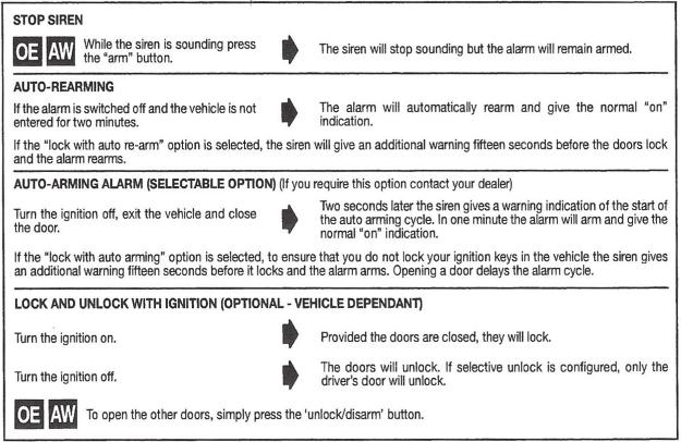
62 SECURITY 10-3


63 SECURITY 10-4
Motor Caravan OWNERS HANDBOOK. Issue 1
 Motor Caravan OWNERS HANDBOOK Issue 1 CONTENTS WELCOME & INTRODUCTION... 1-1 End Of Life Vehicle Directive... 1-1 Elddis Technical Approvals... 1-1 GENERAL SAFETY... 2-1 Please read before using your new
AUTOQUEST. Motor Caravan OWNERS HANDBOOK. Issue 3
 AUTOQUEST Motor Caravan OWNERS HANDBOOK Issue 3 CONTENTS WELCOME & INTRODUCTION... 1-1 End Of Life Vehicle Directive... 1-1 Explorer Group Technical Approvals... 1-1 GENERAL SAFETY... 2-1 Please read before
Motor Caravan OWNERS HANDBOOK. Issue 1
 Motor Caravan OWNERS HANDBOOK Issue 1 CONTENTS WELCOME & INTRODUCTION... 1-1 End Of Life Vehicle Directive... 1-1 Elddis Technical Approvals... 1-1 GENERAL SAFETY... 2-1 Please read before Using Your new
Touring Caravan OWNERS HANDBOOK. Issue 3
 Touring Caravan OWNERS HANDBOOK Issue 3 CONTENTS WELCOME AND INTRODUCTION... 1-1 Model Year... 1-1 Elddis Technical Approvals... 1-1 GENERAL SAFETY... 2-1 Please read before using your new caravan... 2-1
Touring Caravan OWNERS HANDBOOK. Issue 1
 Touring Caravan OWNERS HANDBOOK Issue 1 CONTENTS WELCOME AND INTRODUCTION... 1-1 Model Year... 1-1 Compass Group Technical Approvals... 1-1 GENERAL SAFETY... 2-1 Please read before using your new caravan...
Touring Caravan OWNERS HANDBOOK. Issue 3
 Touring Caravan OWNERS HANDBOOK Issue 3 CONTENTS WELCOME AND INTRODUCTION... 1-1 Model Year... 1-1 Elddis Technical Approvals... 1-1 GENERAL SAFETY... 2-1 Please read before using your new caravan... 2-1
Familly Motorhome Guide
 Familly Motorhome Guide Index Table of Contents The outside of the Motorhome...3 Driving the Motorhome... 6 Dimensions of the Motorhome:... 6 Power hook up... 6 Storage compartments... 7 Rear camera...
2-Berth Motorhome without shower and toilet Automatic transmission. Longford Caravan Park, Longford
 2-Berth Motorhome without shower and toilet Automatic transmission Longford Caravan Park, Longford GENERAL Be familiar with advisory stickers on the windscreen. - note unsealed road travelling warnings.
Luxury Motorhome Guide
 Luxury Motorhome Guide PLEASE DO NOT REMOVE 1 Table of Contents The outside of the motorhome... 3 Outside of the vehicle diagram... 4 Driving the motorhome... 5 Dimensions of the motorhome... 5 Power hook
Swift Motorhomes Owner's Service Handbook
 Swift Motorhomes Owner's Service Handbook Motorhome Details IMPORTANT Enter all your motorhome details on this page (see specification in this handbook). Registration Number Supplied and Pre-delivery Inspection
Touring Caravan OWNERS HANDBOOK. Issue 1
 Touring Caravan OWNERS HANDBOOK Issue 1 CONTENTS WELCOME AND INTRODUCTION... 1-1 Model Year... 1-1 Compass Group Technical Approvals... 1-1 GENERAL SAFETY... 2-1 Please read before using your new caravan...
OWNER S HANDBOOK TRACKER AND APACHE.
 OWNER S HANDBOOK TRACKER AND APACHE www.auto-trail.co.uk together we re going places www.auto-trail.co.uk together we re going places 1 Important Your motorhome makes use of many complex systems and services.
Bessacarr Motorhomes Owner's Service Handbook
 Bessacarr Motorhomes Owner's Service Handbook Motorhome Details IMPORTANT Enter all your motorhome details on this page (see specification in rear of this handbook). Registration Number Supplied and Pre-delivery
OWNERS HANDBOOK Touring Caravans
 OWNERS HANDBOOK Touring Caravans 2008 CONTENTS WELCOME AND INTRODUCTION... 1-1 Model Year... 1-1 Explorer Group Technical Approvals... 1-1 GENERAL SAFETY... 2-1 Please read before using your new caravan...
SINGLE BURNER STOVE IMPORTANT OPERATING INSTRUCTIONS COOKING & STORAGE POSITION PARTS IDENTIFICATION
 SINGLE BURNER STOVE OPERATING INSTRUCTIONS PARTS IDENTIFICATION Electronic Lighter Ignites the burner. Liquid Guard Holds liquid overflow. Windshield Prevents flame from being extinguished by wind. Ensures
CONGRATULATIONS OPERATIONS ANTENNA (IF APPLICABLE) Congratulations on purchasing your Frontline Campervan.
 Congratulations on purchasing your Frontline Campervan.") CONGRATULATIONS ANTENNA (IF APPLICABLE) You may have purchased a foldaway antenna for your campervan. To set this up, take it out from the packaging and join together (fig.18). Attach the pole to the clips
CONGRATULATIONS ANTENNA (IF APPLICABLE) You may have purchased a foldaway antenna for your campervan. To set this up, take it out from the packaging and join together (fig.18). Attach the pole to the clips
Model. Model Year. Motorhome Serial No.
 All the illustrations and descriptive matter in this handbook are intended to give a general idea of the motorhome. Changing market and supply situations may prevent us from maintaining the exact specification
A few days before you set off. 1. Clean
 The summer soon comes around! Now the weather s getting a bit warmer many of us are planning to take our caravan or motorhome out of storage, and hit the road for our first getaway of the year. If your
Swift Motorhome Owner's Service Handbook
 Swift Motorhome Owner's Service Handbook Motorhome Details IMPORTANT Enter all your motorhome details on this page (see specification in rear of this handbook). Registration Number Supplied and Pre-delivery
Read all instructions and warnings before using this fireplace. WARNING
 Frame User Manual 1 Operating Manual Thank you for purchasing this Signi Fires product. Signi Fires is very safety conscious, we have taken every care in designing, manufacturing and assembling your Signi
Touring Caravan OWNERS HANDBOOK. Issue 1
 Touring Caravan OWNERS HANDBOOK Issue 1 CONTENTS WELCOME AND INTRODUCTION... 1-1 Model Year Designation... 1-1 Elddis Technical Approvals... 1-1 GENERAL SAFETY... 2-1 Please read before using your new
Manufactured in New Zealand Metal Fab Industries Ltd PO Box Greenmount Auckland
 Manufactured in New Zealand Metal Fab Industries Ltd PO Box 58-473 Greenmount Auckland Www.metalfab.co.nz LOGAIRE STAINLESS STEEL BBQ 2,3 & 4 Burner Models IMPORTANT Please read all instructions before
Voice Mail: (815) Fax: (815) OWNERS MANUAL
 Fax: (815) OWNERS MANUAL") www.countryhomescampers.com Email: info@countryhomescampers.com Voice Mail: (815) 346 3337 Fax: (815) 346 3337 OWNERS MANUAL Introduction: Your Country Homes Camper has been engineered and built with a
www.countryhomescampers.com Email: info@countryhomescampers.com Voice Mail: (815) 346 3337 Fax: (815) 346 3337 OWNERS MANUAL Introduction: Your Country Homes Camper has been engineered and built with a
INSTANT GARAGE MODEL NO: CIG81224 ASSEMBLY INSTRUCTIONS PART NO: ORIGINAL INSTRUCTIONS
 INSTANT GARAGE MODEL NO: CIG81224 PART NO: 3503578 ASSEMBLY INSTRUCTIONS ORIGINAL INSTRUCTIONS GC1117 INTRODUCTION Thank you for purchasing this CLARKE Instant Garage. When erected, the CIG81224 garage
Touring Caravan OWNERS HANDBOOK. Issue 2
 Touring Caravan OWNERS HANDBOOK Issue 2 CONTENTS WELCOME AND INTRODUCTION... 1-1 Model Year... 1-1 Elddis Technical Approvals... 1-1 GENERAL SAFETY... 2-1 Please read before using your new caravan....
CONTENTS CONTENTS-1. MY2015/Rallye
 Touring Caravan OWNERS HANDBOOK Issue 1 CONTENTS WELCOME AND INTRODUCTION... 1-1 Model Year Designation... 1-1 Compass Technical Approvals... 1-1 GENERAL SAFETY... 2-1 Please read before using your new
INSTRUCTIONS MANUAL CAST IRON STOVE
 INSTRUCTIONS MANUAL CAST IRON STOVE CA-SGB06 Warning: Use outdoors only Read the instructions before using the appliance and retain for future reference. 1 These instructions give some important information
TCWS54 SEE THRU DIAMOND BURNER INSTALLATION KIT INSTRUCTIONS
 INSTALLER: Leave this manual with the appliance. CONSUMER: Retain this manual for future reference. These instructions are supplementary to the Installation and Operating Instructions supplied with the
Instructions for use, installation, and connection. Gas Built in Hob
 Instructions for use, installation, and connection Gas Built in Hob RB3311SGBS RB3312SGBS RB3311DGBS RB3311MGBS RB3311NGBS RB6313SGBST RB6323SGBST RB6314SGBS RB6313DGBST RB6313MGBST RB7312SGBS RB7313SGBST
/ :16 Technical data / Season 2019 Action 361 LT
 Technical data / Season 2019 DIMENSIONS AND WEIGHTS Total length (including tow bar) (mm) 5215 Body length (mm) 4010 Internal length (mm) 3610 Total width (mm) 2196 Internal width (mm) 2080 Total height
Therme storage water heater. Table of contents. Symbols used. Symbols used Symbol indicates a possible hazard. Installation instructions
 Therme storage water heater Table of contents Symbols used... 8 Installation instructions Water supply... 9 Choice of location... 9 Installation of the Therme... 9 Fitting the draining and venting valve...
Parkes series caravan. customer guide
 Parkes series caravan customer guide Owners Name: Model: VIN #: Preparing vehicle Brake controller fitted. Yes: Tow tongue suitable for 3.5T. Yes: Hand over check list Locks / keys. Yes: Pole bag. Yes:
/ :00 Technical data / Season 2019 Altea SEVERN
 Technical data / Season 2019 DIMENSIONS AND WEIGHTS Total length (including tow bar) (mm) 7495 Body length (mm) 6020 Internal length (mm) 5372 Total width (mm) 2296 Internal width (mm) 2170 Total height
Issue 1. Touring Caravan OWNERS HANDBOOK
 Touring Caravan The Explorer Group Limited Delves Lane, Consett, Co. Durham DH8 7PE Telephone: 01207 699000 Facsimile: 01207 699001 www.explorer-group.co.uk All the illustrations and descriptive matter
Gas Conversion Kits and Instructions
 Gas Conversion Kits and Instructions INSTALLATION FORM RGM 432/433-GC (Version D.1) Obsoletes Form RGM 432/433-GC (Version D) APPLIES TO: Model FT and Model SFT All gas conversion must be done by a qualified
Product instruction manual Ream Cutting Systems RE3943, RE3946, RE3947, RE3971, RE3952E
 Product instruction manual Ream Cutting Systems RE3943, RE3946, RE3947, RE3971, RE3952E The Trimfast Ream Cutters are reliable, high performance cutters that will give you the results you need quickly
Hitch Hiker Operating Instructions
 1 Hitch Hiker Operating Instructions Read Completely and Carefully Before Operating The Hitch Hiker is designed as an electric pedal assist system. A pedal assist system helps the riders propel the cycle
CARAVAN SALON DÜSSELDORF Page 1 of 5
 Page 1 of 5 1.0 1 Caravans / Trailers 5.1.2 Top extensions and sleeper roofs 1.1 Caravans 1.2 Fold-down caravans 1.3 Tent caravans 1.4 Off-road and cross-country trailers 1.5 Sport and recreational trailers
CARAVAN SALON DÜSSELDORF Page 1 of 5
 Page 1 of 5 1.0 1 Caravans / Trailers 5.1.2 Top extensions and sleeper roofs 1.1 Caravans 1.2 Fold-down caravans 1.3 Tent caravans 1.4 Off-road and cross-country trailers 1.5 Sport and recreational trailers
AWNING CONTROL KIT 98GCK-33B
 AWNING CONTROL KIT 98GCK-33B REV.07282015 RV AWNING PRODUCTS 1361 CALLE AVANZADO, SAN CLEMENTE, CA 92673 (800) 382-8442 FAX (949)276-5500 www.girardrv.com AC MOTOR CONTROL MODULE GC274B INSTALLATION and
SMART BIO-ETHANOL ELECTRONIC BURNER
 SMART BIO-ETHANOL ELECTRONIC BURNER User s Manual What s in the box: Smart Burner Remote Control AC Adapter Filling Hose User s Manual 1pc 1pc 1pc 1pc 1pc Preparations Remove all packaging materials prior
Data Sheet. Electricity for campers and caravanners. Safety is paramount. Data Sheet
 Data Sheet 30 Data Sheet Electricity for campers and caravanners Using electricity on a campsite When you connect to a campsite electric hook-up point you are able to receive an electricity supply as you
INSTALLER AND OWNER GUIDE
 5118237/01 Model 0581901 Chester Log Effect Electric Stove This guide is intended to help you install and care for your Baxi Fires Division electric stove. Please read carefully before installing and using
Crusader Training updated 11/1/16
 Crusader Training updated 11/1/16 High Gloss Exterior Whether your customer takes the time to wax their camper, or not, the high gloss gel coat is going to look great for years to come Crusader is equipped
Owners Handbook Motorhomes
 Owners Handbook 2003 Motorhomes All the illustrations and descriptive matter in this handbook are intended to give a general idea of the Motorhome. Changing market and supply situations may prevent us
Style # Laguna Propane Tank Cover Owner s Manual
 Style # 26100117 Laguna Propane Tank Cover Owner s Manual Warning: For outdoor use only DO NOT use for cooking DO NOT use under any overhead enclosure Manufactured as Model # 6561 in China for: Restoration
TWO BURNER STAINLESS STEEL PROPANE STOVE
 ROTATE TO LIGHT 842-A250-0_SSCmpStove.qxd 11/26/03 2:59 PM Page 1 OWNER S MANUAL FAILURE TO FOLLOW ALL S AND INSTRUCTIONS IN THIS MANUAL COULD LEAD TO PERSONAL INJURY, INCLUDING DEATH. RETAIN THIS MANUAL
INSTRUCTIONS FOR INSTALLATION, USE AND MAINTENANCE YSEN
 INSTRUCTIONS FOR INSTALLATION, USE AND MAINTENANCE YSEN READ THE INSTRUCTION BOOKLET AND THESE SUPPLEMENTARY INSTRUCTIONS CAREFULLY BEFORE INSTALLATION These instructions together with those in the instruction
Harrie Leenders Fuga el - Instructions for Installation, Use and Maintenance INSTRUCTIONS FOR INSTALLATION, USE AND MAINTENANCE
 INSTRUCTIONS FOR INSTALLATION, USE AND MAINTENANCE FUGA el 1 2 1. Flue 2. Case 3. Ceramic glass 4. Aeration slide 5. Convection fins 6. Door handle 7. Base 3 4 READ THE INSTRUCTION BOOKLET AND THESE SUPPLEMENTARY
The sixth generation of a design icon
 The sixth generation of a design icon Beautifully converted by Volksleisure 1 Volksleisure believe you need to select a campervan that is right for the job and has multi usage, that way you ll get your
Caravans. The. Camper Trailer. Challenger. The best value camper trailer in Australia.
 Caravans The Camper Trailer The best value camper trailer in Australia www.golfcampers.com.au Golf & Bush challenger Now Available in 4 Layouts...including Shower/Toilet! The Bush 1 GOLF has a strong tradition
Country. Instruction. Valley.
 Instruction Country www.combicamp.com Valley Contents UK Instruction 3 Before you set out 4 Hitching the COMBI-CAMP 5 Opening the trailer and erecting the tent 6 Final adjustment 7 Integrated sun canopy
Operator's Manual. Model: RY10MK-PRO MPN: RA-MLT Gallon Direct Fire Melter Kettle Burner Model with Adjustable Flame-Out Valve
 Operator's Manual Model: RY10MK-PRO MPN: RA-MLT-0009 10 Gallon Direct Fire Melter Kettle Burner Model with Adjustable Flame-Out Valve U.S. Patent No. 9,739,021 For Technical Support Please Visit www.rynoworx.com
INSTALLATION INSTRUCTIONS
 INSTALLATION INSTRUCTIONS Accessory HATCH KIT Application 2009 ELEMENT Publications No. AII 41008 Issue Date DEC 2008 PARTS LIST Tent bag 13 Stakes 4 Guide ropes Tent 2 Awning pole caps Gear loft 2 Tie
Maintenance 45 Serie CAUTION. Before resetting your electronic card that displays an error code.
 29-10-2013 CAUTION Before resetting your electronic card that displays an error code. Error Code H Service the stove COMPLETELY as described in this manual. Check the chimney pipe. Error Code O Service
AFC-50 Automatic French Fry Cutter Instruction Manual
 AFC-50 Automatic French Fry Cutter Instruction Manual Fry Factory Inc. 67 Watts Ave, Charlottetown, PEI, C1E 2B7, Canada Phone: 902-368-2900 Fax: 902-368-8645 Email: info@fryfactoryinc.com Website: www.fryfactoryinc.com
Payload - what is it? The weight of equipment and personal possessions you can carry in your motorhome without overloading it
 KNOW YOUR PAYLOAD Payload - what is it? The weight of equipment and personal possessions you can carry in your motorhome without overloading it Why is it so important to understand Payload? Safety to avoid
Quality with Style. Swift Caravans Warranty & Service Handbook
 Quality with Style Swift Caravans 005 Warranty & Service Handbook Warranty... What to do if you Require Assistance... Annual Service/Inspection Record...5 Specifications...8 Wiring Diagrams Road Lights...3
PROPANE SAFETY CHARACTERISTICS OF PROPANE
 CHARACTERISTICS OF PROPANE Propane is transported and stored as a liquid. Propane (sometimes called LPG or LP-gas) is a colorless and odorless gas. An odorant is added to propane to give it an awful smell,
D. LeBlanc. Montérégie, Québec Zion National Park, Utah, USA
 series D. LeBlanc Montérégie, Québec Zion National Park, Utah, USA The HÉLIO O Series offers all you outdoors enthusiasts the chance to get away from your everyday routine in complete comfort. It happens
INSTALLATION INSTRUCTIONS
 INSTALLATION INSTRUCTIONS Accessory HATCH KIT Application 2014 CR-V Publications No. AII 50018 Issue Date JULY 2013 Put this information in the glove box with the vehicle owner s manual PARTS LIST 4 Guide
RV Manual. Four Winds 29, Ford E450
 RV Manual Four Winds 29, Ford E450 Electric Power Source Generator Power Master Battery Switch AC / Heat Water Lavatory Propane Backup Camera Cable Car Radio TV / DVD Player Moon roofs Stove / Oven Microwave
- a useful website for owners and enthusiasts of VW T4 Campervans
 L he Explorer's sleek design and smooth CRP and aluminium finish delivers real aerodynamic performance, together with independent suspension both front and rear- it's a dream to drive.. i \nside and out,
Live Riveted. Dream. Travel. Explore. Live. Your Airstream adventure awaits...
 2018 Live Riveted Dream. Travel. Explore. Live. Your Airstream adventure awaits... 2018 International range Missouri * * * Yukon * transforms to become the base for the L-shaped seating arrangment. * transforms
/ :49 Technical data / Season 2019 Alpina MISSOURI
 Technical data / Season 2019 DIMENSIONS AND WEIGHTS Total length (including tow bar) (mm) 8246 Body length (mm) 6761 Internal length (mm) 6142 Total width (mm) 2460 Internal width (mm) 2310 Total height
CONVERSION INSTRUCTIONS
 CONVERSION INSTRUCTIONS Natural Gas to Propane Gas Conversion Kit For Thermador Professional Cooktops and Ranges Model STARLPKIT Part No. 35-00-682 Contains 7mm Hex Main Orifices This kit is used to convert
LP/High Altitude LP/High Altitude Natural Gas Conversion Kit For United States Installations
 LP/High Altitude LP/High Altitude Natural Gas Conversion Kit For United States Installations Installation Instructions For Model Series G Furnaces, P(G,N) Gas/Electric Appliances, and R Gas/Electric Appliances
GAS STOVE GUARD for natural gas and propane stoves
 GAS STOVE GUARD for natural gas and propane stoves OPERATING INSTRUCTIONS September 18, 2017 STOVE GUARD is not designated for use with gas stoves with pilot light. STOVE GUARD is an electronic safety
INSTALLATION INSTRUCTIONS
 INSTALLATION INSTRUCTIONS Accessory HATCH KIT Application 201 PILOT Publications No. VERSION 1 Issue Date 201 PARTS LIST Stake bag Tent bag 13 Stakes 4 Guide ropes Tent 2 Awning pole caps 2 Tie straps
THE ALL NEW PACIFIC ISLANDER SPECIFICATIONS. Australian craftsmanship. meets quality and style. DEALER STAMP CHASSIS
 THE ALL NEW PACIFIC ISLANDER SPECIFICATIONS CHASSIS 6" Road Runner Chassis with 6" A-Frame 8" Jockey Wheel Single axle 2.6 Dexter Torflex Suspension with 12 brakes Tandem axle 2800kg to 3100kg Alko Leaf
Getting Started Guide
 Getting Started Guide Assembly Instructions User Guide Table Top Maintenance Warranty Information (800) 445-4559 www.designingfire.com Fax: 651-305-6347 @designingfire.com #253915-2528907 Installers: Please
Product information Truma VarioHeat and E-Kit. July 2018
 Product information Truma VarioHeat and E-Kit July 018 Truma VarioHeat The new compact Truma heaters for motor homes, caravans and vans. Truma VarioHeat eco and Truma VarioHeat comfort are of an identical
General Information: The BunduTop standard size is 2100 x 1350 x 300 mm when closed, and 2100 x 1350 x 1000 mm when open.
 General Information: The BunduTop standard size is 2100 x 1350 x 300 mm when closed, and 2100 x 1350 x 1000 mm when open. (But PLEASE NOTE you can order a custom sized BunduTop up to 1.6m wide and 3m long)
Blue Series Hot Melt Hose with RediFlext II Hanger System
 Instruction Sheet P/N 1124594_01 Blue Series Hot Melt Hose with RediFlext II Hanger System Safety WARNING! Allow only personnel with appropriate training and experience to operate or service the equipment.
Kontrol Kube Advanced Owners Manual
 Mobile Containment. Simplified. TM Kontrol Kube Advanced Owners Manual KONTROL KUBE www.kontrolkube.com 800.343755 1 IMPORTANT SAFETY INFORMATION SAVE THESE INSTRUCTIONS. CAREFULLY READ AND FOLLOW THESE
/ :18 Technical data / Season 2019 Adora SEINE
 Technical data / Season 2019 DIMENSIONS AND WEIGHTS Total length (including tow bar) (mm) 8240 Body length (mm) 6779 Internal length (mm) 6142 Total width (mm) 2299 Internal width (mm) 2170 Total height
EB300. Ethanol Burner. User s Manual Installation Instructions
 EB300 Ethanol Burner User s Manual Installation Instructions EB300 Burner Burner Lid User s Manual What s in the box: 1pc 1pc 1pc Installation Instructions EB300 - User s Manual The Ignis Ethanol Burner
Crusader Training. updated 11/1/17
 Crusader Training updated 11/1/17 New Graphic s and Large Exterior Grab Handle New exterior mounted Furrion speakers provide better sound quality without creating large holes in sidewall MORryde ZG entry
Ponderosa Volunteer Fire Association, Inc. CAMPER 63 & Generator Usage Final August 2017 Purpose & Scope:
 Ponderosa Volunteer Fire Association, Inc. CAMPER 63 & Generator Usage Final August 2017 Purpose & Scope: Camper 63 is available for personal use to the membership of the Ponderosa FD when not being used
S E L E C T I O N. Abdominal Crunch. User manual
 and S E L E C T I O N T H E S T R E N G T H E V O L U T I O N User manual and and The identification plate of the and manufacturer, affixed along side the seat on the frame of the weight stack, gives the
Luxury Bespoke Motorhomes. euro-treka RANGE.
 Luxury Bespoke Motorhomes euro-treka RANGE www.moto-trek.co.uk About us After many successful years as the market leader producing high quality luxury vehicles for the equestrian and motorsport markets,
ERIBA Living. Highlights. Characteristics. The ideal caravan for the whole family.
 ERIBA Living ERIBA Living Highlights The ideal caravan for the whole family. With its chic design and attractive colour scheme, the ERIBA Living will delight both the young and young at heart. The living
Primrose Awnings Half Cassette Manual & Electric Instructions
 Primrose Awnings Half Cassette Manual & Electric Instructions Contents for 2.5m, 3m Awnings 4 x Expansion bolts (2 per bracket)** 2 x brackets 1 x Awning Contents for 3.5m, 4m Awnings 6 x Expansion bolts
User Manual. 1000W Stackable 1.2 Cu. Ft. Commercial Microwave. Model: 180MW112T 05/2017. Please read and keep these instructions. Indoor use only.
 1000W Stackable 1.2 Cu. Ft. Commercial Microwave Model: 180MW112T 05/2017 Please read and keep these instructions. Indoor use only. IMPORTANT SAFETY INSTRUCTIONS When using electrical equipment, basic
USER MANUAL BMU WORKCAGE. CONFORM TO THE MACHINE DIRECTIVE 2006/42/EC and to EN1808 (1999)
") USER MANUAL BMU WORKCAGE CONFORM TO THE MACHINE DIRECTIVE 2006/42/EC and to EN1808 (1999) All persons operating this equipment must read and completely understand this manual. Any operation in violation
USER MANUAL BMU WORKCAGE CONFORM TO THE MACHINE DIRECTIVE 2006/42/EC and to EN1808 (1999) All persons operating this equipment must read and completely understand this manual. Any operation in violation
INSTALLATION AND USE OF THE AIR ASSISTED SYSTEM FOR JETSLIDE - AIRASSIST from CANDOCK
 INSTALLATION AND USE OF THE AIR ASSISTED SYSTEM FOR JETSLIDE - AIRASSIST from CANDOCK I) INTRODUCTION Thank you for the acquisition of the Air Assisted System called Air ASSIST from Candock. Before installing
Glammbox Crea7ion.E. GlammFire. Crea7ion by GlammFire. GlammFire
 Crea7ion by Wall Mounted Fireplaces// Glammbox 420 Glammbox 420 DF Glammbox 450 Glammbox 450 DF Glammbox 770 Glammbox 770 DF Glammbox 1150 Glammbox 1150 DF Glammbox 1600 Glammbox 1600 DF Glammbox 2150
CAMPING VAN MANUAL. STEP 1 : Unzip awning bag. STEP 2 : loosen valcro tabs & slowly unroll awning until leading edge is exposed.
 CAMPING VAN MANUAL AWNING A 1.5 metre roll out bag awning features off the side of the Camping Van. - Photos are of our Cape Camper awning, as assembling is identical. STEP 1 : Unzip awning bag. STEP 2
Adria Altea 432PX Instructional guide by Perfect Break Caravans
 Adria Altea 432PX Instructional guide by Perfect Break Caravans Setting up to tow European caravans must not attach to a normal tow ball setup. Although the tow ball itself is the same size as normal it
Est A TRADITION OF EXCELLENCE INSTRUCTION BOOK.
 Est. 1887 A TRADITION OF EXCELLENCE INSTRUCTION BOOK www.wolseleygrooming.co.uk Stockshop (L.E.) Ltd., Lodge Trading Estate, Broadclyst, Exeter EX5 3BS Email: service@stockshop.co.uk Tel: 01392 460077
t420 Barbecue Assembly Manual
 t20 Barbecue Assembly Manual 85-300-2 (G510) Propane 85-3005-0 (G5105) Natural Gas 1 Year limited Warranty Read and save manual for future reference. If pre-assembled, leave this manual with unit for consumer
Installation and User s Manual 12 x 10 MOTORIZED AWNING
 12 x 10 MOTORIZED AWNING Installation and User s Manual 12 x 10 MOTORIZED AWNING 088-1763-0 Stop Please read and understand this manual before any assembly or use of this product. Before beginning assembly
TUBULAR BURNER CONVERSION KIT AGCK-TBXX / AECK-UBXX
 TUBULAR BURNER CONVERSION KIT AGCK-TBXX / AECK-UBXX IMPORTANT - READ ALL INSTRUCTIONS BEFORE YOU BEGIN THE INSTRUCTIONS HEREIN SHOULD BE PERFORMED BY A QUALIFIED SERVICE TECHNICIAN. THE GRILL MUST BE COMPLETELY
Cooking Booth Construction and Location (See Figure 1 and 2 for diagrams):
:") Page: 1 Of 9 Scope: This Standard shall apply to all cooking equipment, the including but not limited to: fryers, grills, BBQ s (both solid and LPG fuel supplied) and ovens. Use in or adjacent to booths
Page: 1 Of 9 Scope: This Standard shall apply to all cooking equipment, the including but not limited to: fryers, grills, BBQ s (both solid and LPG fuel supplied) and ovens. Use in or adjacent to booths
Meat Slicer INSTRUCTION MANUAL CAUTION! ONE YEAR LIMITED WARRANTY
 ONE YEAR LIMITED WARRANTY INSTRUCTION MANUAL The original registered owner of this product should contact SKYFOOD EQUIPMENT LLC at 305-868-16 for any warranty problems or service. SKYFOOD EQUIPMENT LLC
Mooveo P6 Quick User Guide
 Mooveo P6 Quick User Guide Loading up Driving off Arriving on Site Cooking and Heating Night Time Height: 2.75m, Width: 2.3m, Length: 5.99m, (plus bike rack if fitted), Max Weight 3,500kg In Case of Difficulty
Contents. Introduction...3 Description...3. Pack Contents...4. Rada Heavy Duty EV Shower Fittings Right Angled Connector (RAC)...
...") SHOWER FITTINGS PRODUCT MANUAL IMPORTANT Installer: This manual is the property of the customer and must be retained with the product for maintenance and operational purposes. Contents Introduction...3
SHOWER FITTINGS PRODUCT MANUAL IMPORTANT Installer: This manual is the property of the customer and must be retained with the product for maintenance and operational purposes. Contents Introduction...3
Model. Oasis Automatic and Manual RV Door Awning System INSTALLATION & OPERATING INSTRUCTIONS
 Oasis Automatic and Manual RV Door Awning System USA SERVICE OFFICE Dometic Corp. 509 So. Poplar St. LaGrange, IN 46761 260-463-4858 CANADA Dometic Dist. 866 Langs Dr. Cambridge, Ontario CANADA N3H 2N7
Ultraflow Compact Housing and Winter Kit
 Ultraflow Compact Housing and Winter Kit Operating instructions Page 2 Installation instructions Page 8 To be kept in the vehicle! Comfort on the move Ultraflow Compact Housing and Winter Kit 1 Compact
TENTS, CANOPIES AND TEMPORARY MEMBRANE STRUCTURES
 INFORMATION BULLETIN TENTS, CANOPIES AND TEMPORARY MEMBRANE STRUCTURES Code Reference: Title 19 California Code of Regulations California Fire Code (CFC), 2001 Edition, Article 32 California Building Code