Pilot s Guide - Guide du Pilote
|
|
|
- Ada Wilson
- 5 years ago
- Views:
Transcription

1 Pilot s Guide - Guide du Pilote
2 CREDITS TABLE OF CONTENTS PRODUCERS: Victor Fred Goldman, Racz & Victor Fred Racz Goldman PROGRAMER: PROGRAMMER Eric Marciano Eric Marciano LEAD ARTIST: Tamas Szabo 3D ARTISTS Den 3D ARTIST: Okan, Tamas Szabo Tamas Szabo, Victor Racz, Vyacheslav & Victor Racz Fomin 2D PANEL ARTISTS ART: Peter Balogh, Tamas Szabo & 2D Victor ARTIST: Racz Peter Balogh, Tamas Szabo, Christophe Modave, Victor Racz World FLIGHT map DYNAMICS: on the Corporate Jetliner plasma screens Rob Young is provided by REPAINTS SOUND: Peter Mike Hambly, Balogh, Eric Kittisak Marciano, Rukkaew Victor Racz Stéphane OBER USER HANDBOOK: FLIGHT Eric Marciano, DYNAMICS Eric Belvaux Rob TESTERS: Young Chip Barber, Charlie, Les Dillon, W. SOUND David Scobie, Craig Smoothey, Neil Perrin Mike Hambly, Eric A very Marciano special thanks to: & Marc Victor Brodbeck Racz MANUAL Eric Marciano, Eric Belvaux WELCOME ABOARD! A. Installation B. Extra C. Quick Start D. 2D & 3D Cockpits E. Cabin & Doors TUTORIAL FLIGHT INTRODUCTION SETUP FLY-BY-WIRE AUTOFLIGHT EFIS APPENDICES QUALITY FIRST! By not making illegal copies and purchasing only original WILCO PUBLISHING products, you will allow us to continue developing and improving the quality of our software. THANK YOU. The code used in Wilco Publishing products may under no circumstances be used for any other purposes without the permission of Wilco Publishing and its developers. Microsoft and Windows are trademarks or registered trademarks of Microsoft Corporation in the United States and/or other countries. Acrobat Reader is a registered trademark of Adobe. Order your Airbus Series Volume 1 version! Complete your Airbus Series collection with the following elements : - Airbus A318, A319, A320, A321, - Airbus Corporate Jetliner - 60 minutes of videos (Just Planes) featuring breathtaking take-offs & landings. For more information, please visit 2 (c) 2007 Wilco Publishing
3 WELCOME ABOARD! TUTORIAL FLIGHT A. INSTALLATION Installation is automatic. Insert the CD (or double-click on the downloaded file) and Autorun will take you to the start-up screen. If Autorun is disabled on your system, open Windows Explorer or My Computer, browse to your CD Rom drive and double click Wilco_Airbus2_x.exe (where x is your version). Once setup is running, follow the on-screen prompts and ensure that the installation points directly to the Microsoft Flight Simulator folder (usually C:\Program Files\Microsoft Games\FlightSimulator...). CHECK OUT WILCO PUBLISHING WEBSITE : YOU WILL FIND INFORMATION, NEWS, AND FREQUENTLY ASKED QUESTIONS. B. EXTRA (for CD-Rom version only) We have included a full set of files and videos on your CD-Rom. Use your Windows Explorer to locate them into the EXTRA WILCO directory. To fully enjoy the 3D Virtual Cockpit, the Track IR lets you control your field of view in flight simulators by simply looking around by few degrees. Track IR is available from Wilco Publishing C. QUICK START 1. To Pilot one of the Airbus 1. Start Flight Simulator 2. From the menus, select AIRCRAFT 3. Choose feelthere/wilco Airbus Series Vol.2 4. Select the Aircraft Model of your choice. 5. Select the livery of your choice The liveries are installed on your CD-Rom or available from Wilco Publishing website if you bought the download version. 2. Engines Start Up Use CTRL+E to start the engines. To start up engines from a 'Cold & Dark Cockpit', please refer to the next pages for complete procedures. D. 2D & 3D COCKPITS 2D Panel Views The following 2D panel views are available using the following key combinations : SHIFT+1 = Main Panel Background SHIFT+2 = Main Panel SHIFT+3 = Pedestal SHIFT+4 = Overhead SHIFT+5 = MCDU SHIFT+6 = PFD SHIFT+7 = ND SHIFT+8 = EWD SHIFT+9 = SD 3D Virtual Cockpit Views Display the different Cockpit views using the normal Flight Simulator keystroke, S under FS 2004 and A under FS X. All controls found on the main 2D panels are functional within the virtual cockpit. Mouse clicking on the FMC opens the 2D FMC in a separate window. Mouse clicking on some specific screens open a 2D window : FMS, EADI... E. CABIN & DOORS The Cabin Under Flight Simulator 2004, to move and walk inside the cabin, we have included a utility on the CD-Rom (directory : EXTRA / F1View), also available from our website. This utility is kindly offered by Flight 1. This module requires a wheel-mouse (a center wheel that also acts as a center mouse button). Note that this utility is not needed under Flight Simulator X as you can access cabin view through a right-click sub-menu option. Virtual Cockpit Wheel forward moves you forward and wheel backward moves you back. CTRL+forward moves right and CTRL + backward moves left. SHIFT+forward moves up and SHIFT + backward moves down. CTRL+SHIFT+forward zooms out and CTRL+SHIFT+backward zooms in. While in Pan Mode (mouse wheel pressed and held down) inside the Virtual Cockpit : Mouse to the left rotates view to the left. Mouse to the right rotates iew to the right. Moving the mouse forward, away from the user, rotates the view up. Moving the mouse backward, towards the user, rotates the view down. Please refer to the manual for other features list. Under Flight Simulator X, press SPACE to switch to pan mode. Wheel mouse serve as zoom in/out while in pan mode. The Doors To open the external doors : SHIFT + E for the passengers door. SHIFT + E + 2 for the cargo door (from ext). To expand/retract the A330 MRTT refueling boom, it is necessary to assign the FS shortcut defined for Tailhook. TUTORIAL FLIGHT This tutorial describes all the phases of a flight from Toulouse Blagnac (home of the Airbus aircrafts) to Paris Orly, from the cold & dark situation to the landing at destination. FLIGHT SETUP Cold & Dark This tutorial is supposed to begin with a cold & dark aircraft. In order to be in this situation, you can press the "Cold & Dark" button on the configuration window and place your aircraft at LFBO (Toulouse Blagnac) on a parking place. Batteries ON On the overhead panel press both battery switches to turn on the batteries. All Generators ON Even if engines are not running yet, turn the generators on (they are in fault mode because the engines are not running). NAV Lights ON As soon as the aircraft is energized, NAV light should be turned on. Radio Management Panels ON On the pedestal, turn the Radios on using the RMP master switch. External Power Check the overhead panel. If an external power source (GPU) is available, press the EXT PWR switch. Initialization If the MENU page is displayed, press the 1L key or press the INIT key on the MCDU to display the INIT A page. FROM/TO : Enter the departure and arrival airports in the scratchpad and press 1R LFBO/LFPO > 1R The route selection page appears. A route exists between LFBO and LFPO, named LFBOLFPO1. Let s use it by pressing INSERT (6R) Align the IRS by pressing 3R Enter the flight number in the scratchpad and press 3L Enter the cruise altitude in the scratchpad and press 6L > 6L or 330 > 6L or FL330 > 6L Press NEXT PAGE to jump to the INIT B page. ZFWCG/ZFW : Enter the ZFWCG and ZFW in the scratchpad and press 1R 25/59.1 > 1R or use assistance for this (in Beginner and Intermediate modes only) : press 1R with empty scratchpad, the 1R 4 (c) 2007 Wilco Publishing
4 TUTORIAL FLIGHT TUTORIAL FLIGHT again to enter it in the. When ZFW is entered, the Block line appears. Enter the block fuel and press 2R (assistance is also available). Press the F-PLAN key on the MCDU to display the F-PLN page. On the first line, the departure airport (LFBO) is shown. Press 1L to display the Lateral Revision page for this airport. On the LAT REV page, press 1L to display the DEPARTURE page. Select the departure runway and the SID (or NO SID). Press INSERT (6R) to validate, the F-PLN page appears again. Resolve the discontinuity. Scroll down to the arrival airport (LFPO) or press the AIRPORT key on the MCDU to jump directly to the arrival airport. Press the left button adjacent to the arrival airport to display its Lateral Revision page. Press 1R to display the ARRIVAL page. Select arrival runway and STAR (or NO STAR). If the arrival runway changes because of the weather (especially because of wind direction or IFR conditions), you will be able to update it during the flight. Press INSERT (6R) to validate, the F-PLN page appears again. Resolve the discontinuity. At this time, with all the data entered in the and no discontinuity in the flight plan, the predictions are computed and displayed with the flight plan. If you wish, you can enter the Estimated Time of Departure (ETD) by pressing the right key adjacent to the departure airport. The Vertical Revision page appears and you can enter the UTC CSTR by pressing 2R. Now it is time to set the performance data. Press the PERF key on the MCDU and the PERF TO appears to set the takeoff performance. Enter the takeoff flap configuration (1, 2 or 3) and press 3R. In the real aircraft, this information is used as a reminder only for the crew. If you are in Beginner or Intermediate mode, the information is also used by the system if you request assistance for the reference speeds. Suggestion : Use Flap 1 configuration. Enter the FLEX TEMP and press 4R. This temperature will be used by the FADEC if you takeoff using FLEX thrust. Suggestion : A value of 50 is an average value that should work fine. Enter V1, VR and V2 in the 1L, 2L and 3L fields. These speeds are important for the SRS mode during takeoff. As soon as these speeds are entered, the red message SPD SEL disappears from the PFD and the reference speeds appear on the speed tape. Remember you can use the assistance if you are not in Expert mode. Thrust reduction altitude and acceleration altitude can be entered. By default, both altitudes are set to 1500 feet above the departure airport altitude. You can leave this value for the thrust reduction altitude, but the acceleration should be 1500 feet higher than the thrust reduction altitude. To leave the thrust reduction altitude unchanged and update the acceleration altitude to 3200 feet ; /3200 > 5L Press NEXT PHASE to display the other PERF pages for climb, cruise, descent and approach (PERF CLB, CRZ, DES, APPR). Make sure all parameters are OK for you. You should especially check the Cost Index, which determines the speed used for climb, cruise and descent if you use managed speed. ENGINE START APU Start Before being able to start the engines, the APU must be started. On the overhead, press the APU Master Switch ON. Then press the START button. Monitor the APU start sequence of the SD and wait for the APU to be available. External Power If external power was used, turn it off now by pressing the EXT PWR switch. APU Bleed ON Turn on the APU bleed by pressing the APU BLEED switch on the overhead. Beacon Lights ON As the engines will soon be started, the beacon lights must be turned on now using the switch on the overhead panel. Strobes AUTO or ON Strobe lights should be turned on as soon as the aircraft is moving. If you select AUTO, they will automatically turn on as soon as the aircraft is airborne. Signs Turn Seat Belts and No Smoking signs on, or set the auto position to have them automatically managed. Engine Start The APU is available and APU bleed is engaged. The engines are now ready to start. On the pedestal, set the ENG Mode switch to the IGN/START position. You can check on the E/WD that the FADEC have turned on because the amber information is replaced by active displays. ENG 2 Master Switch ON. Check the engine is correctly starting on the E/WD and SD. Wait for the engine 2 to be started completely. ENG 1 Master Switch ON. Monitor the E/WD and SD. When all engines are running, set the ENG mode switch back to the NORM position. 2 minutes after engine start, the takeoff memo will appear on the E/WD. APU Stop As both engines are started, check the generators are turned on. The APU is not necessary any more. Press the APU BLEED switch to turn air bleed off, and press the APU Master Switch to turn the APU off. FCU Check the dash-ball-dash-ball-ball-dash on the FCU to make sure all the settings are OK : speed managed, heading managed, and altitude managed with a target altitude higher than the acceleration altitude. Check the FMA and make sure the CLB and NAV modes are armed. If not, reset the FCU by turning the FD off then on again. CLB and NAV should appear in blue on the FMA. PUSHBACK Flaps Set the flap configuration according to what you have entered in the PERF TO page. Spoilers ARMED Arm the ground spoilers in case of a rejected takeoff. Autobrake MAX (or RTO on the A ) The autobrake should be set to MAX/RTO in case of a rejected takeoff only (never use MAX for landing). Parking Brake RELEASED Release the parking brake to get ready for pushback. Taxi Lights ON Turn on the taxi light before taxiing. Cleared for pushback Ask the ATC for pushback clearance and press the corresponding key (Shift-P by default) to start the pushback. If you have selected a PPU (option available in FS2004 only), you have to steer the aircraft during the pushback. Note : You can also change this sequence by starting the engines during the pushback, as it is often done on the real aircraft. TAXI Cleared to Taxi When pushback is finished and the aircraft is properly positioned, you can ask the ATC for taxi clearance to the departure runway. Thrust During taxi, move the thrust lever in the manual range. Around 40 % N1 should be enough to move the aircraft. Taxiing should be operated at 20 knots, with 10 knots during the 6 (c) 2007 Wilco Publishing
5 TUTORIAL FLIGHT TUTORIAL FLIGHT turns. As soon as the aircraft moves, idle thrust should be enough to keep it going. Flight Controls CHECKED Move all the flight controls in all possible directions and check their movement on the F/CTL SD page, which appears automatically when a flight control moves on the ground. Takeoff Configuration TEST On the ECAM control panel (located on the pedestal), press the TO CONFIG key (or press Shift-Control-T on your keyboard). This action simulates takeoff thrust power and checks all the important settings for takeoff. Landing Lights ON Turn the landing lights on to get ready for takeoff. Parking Brakes SET Before entering the runway for takeoff, set the parking brakes. Takeoff Memo GREEN On the takeoff memo displayed on the E/WD, make sure all the items are green and no blue item remains. Cleared for takeoff Ask the ATC for a takeoff clearance. ALIGN AND TAKEOFF Parking Brakes RELEASED As soon as the takeoff clearance is received, release the parking brakes to enter the runway. Thrust Like for taxiing, use around 40% N1 to taxi to line up on the runway. TCAS Mode ABV On the pedestal, set the TCAS mode to ABV (above) to get ready for climb and watch for potential intruders 8000 feet above the aircraft. Takeoff Thrust If you are cleared for takeoff, push the thrust levers to % N1 and monitor the E/WD to make sure thrust is available. If everything is OK, you can push to the FLEX detent. You can use the TOGA detent for takeoff, but in this flight we decide to save some fuel and use FLEX thrust takeoff. IRS For your information, the IRS are automatically aligned with the GPS position at this time. If the IRS were not perfectly aligned before, you may see the alignment on the ND. FMA As soon as the thrust levers are in the FLEX detent, check that the FMA displays : MAN FLEX 50 in the 1 st column SRS in green in the 2 nd column, in addition to the blue CLB (armed mode) that was already displayed. RWY in green in addition to the NAV message already displayed in blue in the 3 rd column. A/THR in blue in the 4 th column to indicate the autothrust is armed. Stick Position During the takeoff roll, the stick should be pushed half way forward until the speed reaches 80 knots. This stick position can be monitored on the PFD. Yaw Bar As soon as the takeoff thrust is applied, and if the runway has an ILS, the yaw bar appears on the PFD to help you in guiding the aircraft along the runway centerline. Stick Position When the speed is over 80 knots, the stick can be released to come back to the neutral position. Rotation When VR is reached (indicated with a blue circle on the PFD speed tape), pull the stick for the rotation. If the FD is not perfectly stable at this time, take a 15 pitch angle. Landing Gear UP As soon as positive climb is achieved, the landing gear can be retracted. The autobrake will automatically turn off 10 seconds later. Landing Light OFF Even if the landing light is automatically turned off when the gear is retracted, it should be turned off using the overhead switch. Ground Spoilers DISARMED The takeoff can not be rejected so the ground spoilers can be disarmed. CLIMB Thrust Reduction Altitude When the THR RED altitude is reached (1.800 feet in this example), a flashing LVR CLB message appears on the FMA (1 st column). Move the thrust lever back to the CL detent. Note : As the thrust reduces when the levers are moved back to the CL detent, the pilot should anticipate the pitch reduction caused by this thrust reduction. Acceleration Altitude Check the CLB mode becomes active on the FMA (2 nd column). The aircraft will now accelerate to the target speed of 250 knots. S Speed As the aircraft accelerates, you must retract the flaps and slats when the S speed is reached and let the aircraft accelerate to 250 knots feet At feet, the 250 knots speed limit disappears, so the aircraft accelerates to the target climb speed. If you did not change the default cost index of 50, the target speed is 300 knots. Barometric Setting PULL When the transition altitude is reached ( feet by default in Flight Simulator), the barometric setting flashes. Pull the barometric knob to set the STD value. Cruise Altitude As soon as the cruise altitude is reached, check the FMA displays ALT CRZ in the 2 nd column. DESCENT & APPROACH TCAS Before engaging the descent, set the TCAS mode to BLW (below) to monitor potential intruders below the aircraft during the descent. Engage Managed Descent When the top of descent point (T/D) is reached, select a lower altitude (you can select feet) on the FCU and push the ALT knob (left mouse click). Deceleration As the aircraft descends, it will reach the deceleration point, shown as a big D on the ND. At this time, the approach phase automatically engages and the target speed is changed to the Vapp speed, which should be around 140 knots in this case. Note that even if Vapp is shown as the target speed, the actual target speed will be the maneuvering speed before flaps are fully deployed in landing configuration. If you decide to be guided by the Flight Simulator ATC, it is highly probable that your aircraft will never cross the D point. In this case, you have to manually set the approach phase by pressing the ACTIVATE APPROACH PHASE (6L) in one of the PERF pages. ILS ON As the approach phase is engaged, the ILS is automatically tuned to the arrival runway ILS. You can press the ILS button at this time to have the ILS information displayed on the PFD. Flaps Extension As the aircraft descends, you can extend the flaps to help it decelerating and to keep good lift while the airspeed is decreasing. Suggestion : Extend Flaps 1 at around feet. As the aircraft keeps decelerating, you can extend flaps as soon as the VFE NEXT speed is reached. Suggestion : Extend Flaps 2 and 3 as the speed decreases. Landing Configuration Keep following the flight plan (or the ATC instructions if you are guided by ATC). It should align you with the runway. At around feet, get ready for landing: Extend the landing gear Extend full flaps Set LOC mode on the FCU Set Autobrake MED 8 (c) 2007 Wilco Publishing
6 TUTORIAL FLIGHT / INTRODUCTION / SETUP SETUP Ground Spoilers ARMED Note that the landing memo appears when the aircraft reaches feet in approach. Glideslope capture As soon as the localizer is captured (LOC* or LOC displayed on the FMA), you can set the approach mode (APPR) on the FCU. If you want to make an autoland, you can engage the second autopilot at this time. Landing Memo GREEN Make sure all the items on the landing memo are green. If not, take the corrective actions. Short Final Follow the localizer and glideslope, or let the autopilot do it in autoland if you wish. As the aircraft gets closer to the ground, the LAND mode engages, then the FLARE mode. They are shown on the FMA. If you fly manually, just follow the flight director and it will be fine. Thrust RETARD At around 20 feet, an aural warning Retard, Retard is heard. Pull the thrust levers back to idle and let the aircraft gently touch the ground. LANDING Reverse Thrust & Braking As soon as the wheels have touched the ground, you can engage the thrust reversers if you wish. The autobrake makes the aircraft decelerate on the ground. You can take the control at any time by using the brakes. Any action on the brakes automatically disconnects the autobrake system. Exit Runway Exit runway when able. As soon as it is done, retract the flaps and disarm the ground spoilers to retract them. Taxi to the Gate As you taxi to the arrival gate, you may notice the resets 1 minute after the aircraft has touched the ground. Its memory is cleared to make it ready for the next flight. The FMA is also cleared. Last Turn Just before arriving at the gate, you should start the APU to get ready to stop the engines. APU Master Switch ON APU START At the Gate When the aircraft is stopped at the gate, shut it down : Parking Brakes SET ENG 1 Master Switch OFF ENG 2 Master Switch OFF (Remember that the right mouse button must be used to shut down the engines) External Power One minute after the aircraft has stopped and the engines are shut down, the GPU becomes available. Press the EXT PWR switch on the overhead to use it. APU Shut Down As soon as the external power source is available, you can save fuel and turn off the APU by pressing the APU Master Switch. INTRODUCTION HOW TO READ THIS MANUAL? This manual describes the panels and the aircraft systems. Reading this manual is very important to understand how the panels and the systems work, in order to use them efficiently. Within this manual, you will find some notes about the usage of these aircrafts in Flight Simulator. They are written in italics. Each time you read a section in italics, remember it is something related to the implementation of a system in the Flight Simulator context. You will also find some advice provided by real life pilots who fly real Airbus aircraft. This is very useful and aids understanding about how some systems are used. For example, it will help you to answer the question: Why should I use the TRK/FPA guidance mode instead of the HDG/VS mode? It may also let you know when a system should be used, and when it shouldn t. SETUP FS SETUP Key Assignments Some key assignments are suggested for optimal use of the panel. Some of them are not defined by default in Flight Simulator, so their definition is recommended if it has not been done already. The key assignment is available in FS2004 through the pull-down menu Options > Controls > Assignments... and in FSX through Options > Settings > Controls... The suggested key assignments as follows : Standby frequency swap : This commands swaps the active and standby frequencies on the Radio Management Panel (RMP). This device is described later in this documentation. Autopilot arming switch : This command is mapped to the Z key by default. It simulates the autopilot disconnect button located on the sidestick in the real aircraft. This is why it should be assigned to one of your joystick button, if possible. Autothrottle arming switch : This command is mapped to the Shift-R key by default. It simulates the thrust lever instinctive pushbuttons located on the throttle levers in the real aircraft. For this reason, it should be assigned to a button on your throttle device, if possible. Control Sensitivities and Null Zones The sensitivities and null zones of the stick controller (PC joystick or yoke) must be adjusted to have the fly-by-wire working as efficiently as possible. These settings are described in detail in the section dedicated to the fly-by-wire system. Throttle Setup In the real aircraft, the throttle levers have detents that correspond to specific throttle settings. This is detailed in the Autoflight section ( thrust levers paragraph). If you have a single or multiple throttle device, no specific setup is required. The throttle device is acquired to determine if the throttle lever is in a specific detent or not. If you don t have any throttle device and use the keyboard to control the engines, everything works without needing any specific setup, but the use of a throttle device is highly recommended. USER SETUP The aircraft configuration window is accessible through the Wilco Airbus configuration software : 10 (c) 2007 Wilco Publishing


 must be executed must be executed RWY Mode Available on any runway,")
7 SETUP SETUP The configuration window is accessible by pressing the top button labeled Configuration. The Load Manager, key configurator and Fuel Planner will be described in other sections. Note : Than when you configure the aircraft through this configuration tool, any change is taken into account the next time the aircraft is loaded into FS2004 or FSX. In FS2004 In FS2004 only, the configuration window is also accessible when the aircraft is loaded in FS through a new menu that appears in the Aircraft pull-down menu. This cascade menu lets you configure the aircraft with several options, described in the following paragraphs. In FSX In FSX, the configuration window is accessible only through the Wilco Airbus configuration software. Beginner Intermediate Expert Engine Start FS shortcut allowed Full startup sequence Full startup sequence (Ctrl-E key operative) must be executed must be executed RWY Mode Available on any runway, Available only if the runway Available only if the runway (runway lateral as long as the aircraft has a localizer and the has a localizer and the mode) is aligned. departing runway has been departing runway has been entered in the MCDU entered in the MCDU Inertial Information Always available Available only when the IRS Available only when the IRS (aircraft heading/track are aligned are aligned and position) Ref Speeds Automatically computed Automatically computed on Not automatically computed, (V1, VR, V2) with average values request. A warning on the PFD the pilot has to enter them no warning on the PFD if they are not entered in the MCDU. Otherwise, a warning appears on the PFD Gross Weight (GW) Automatically computed Must be entered in the MCDU Must be entered in the MCDU according to FS settings to compute the F, S, and Green to compute the F, S, and Green Dot speed (available on request)dot speed (available on request) Default IRS Alignment 10 seconds 1 minute 10 minutes duration Wind indication on Always visible Not visible if speed is too low Not visible if speed is too low the Navigation Display (unreliable inertial information)(unreliable inertial information) MCDU Assistance Available Available Not available Weight Unit You can select the unit used to display weights (aircraft weight, fuel weight...) The possible choices are kilograms (KG) and pounds (LB). European pilots may prefer the metric system (KG), while US pilots may prefer to use Imperial measures. Panel Sound Volume The panel has its own sounds: warning sounds, GPWS altitude callouts, etc. This slider lets you adjust the panel sound volume independently from the other FS sound settings, such as engine sound volume, cockpit sound volume, etc. User Experience (Realism) This aircraft can be flown in different modes depending on the level of realism you are expecting. Three realism levels are available: beginner, intermediate and expert. To make it simple, beginner users will not have to read quantities of documentation to start the engines and fly the aircraft. Intermediate users will have more realism while enjoying some FS shortcuts. Expert users will have to follow carefully all the required procedures to fly this aircraft. The table explains in detail the differences between the various levels of realism. In summary, if you set the realism to beginner, you will be able to start the engine, take off and land without reading a single page of this manual. Otherwise, you must read the documentation to set up the aircraft properly for take off and flight. IRS Alignment Duration By default, the IRS alignment time depends on the level of realism, as shown in the table above. In the real aircraft, the alignment time is around 10 minutes. For easier use, you can reduce this time and set the value you wish using the slider. Remember that if you change the level of realism, the alignment time will be updated accordingly. MCDU Keyboard Input You may want to use your PC keyboard to enter data into the MCDU. You can do this by selecting a key modifier or a key locker : A key modifier is supposed to be used in combination with the keyboard keys. For example, if you select Shift-Control as the modifier, pressing Shift-Control-L will enter an L character in the MCDU. Note : A key combination may be in conflict with a FS command, such as Shift- Control-L for the aircraft landing lights. The use of a key lock will intercept all the keys to redirect them to the MCDU. For example, if you select Scroll Lock as the key lock and press the Scroll Lock key, the scroll lock LED lights up on your keyboard and any key typed on the keyboard enters a new character into the MCDU. For example, if you press the L key, an L character is entered in the MCDU and the aircraft lights don t change. Pressing the Scroll Lock key again turns the keyboard back in a normal state. Note 1 : Remember that when a locker key (such as Scroll Lock) is used, EVERY key stroke is redirected to the MCDU. Don t be amazed if the ALT key doesn t display the FS menu any more. This is because this key is also intercepted. Press the locker key again for normal 12 (c) 2007 Wilco Publishing


8 SETUP / FLY-BY-WIRE FLY-BY-WIRE keyboard behavior. Note 2 : In FS2004, the Scroll Lock key is defined as the default locker. In FSX, this key is used to display/hide the ATC window, which can also be displayed/hidden using the accent key. For this reason, you should clear the Scroll Lock assignment for the ATC window and make this function accessible through the accent key only. Startup Press the cold & dark button to reset the aircraft in a cold and dark situation, with all the engines and devices turned off. This feature is available only if the aircraft is parked on the ground. Pushback Type This aircraft allow you to choose the type of pushback you want to use. The standard pushback is the default pushback available in Flight Simulator, triggered by the Shift-P key (by default) with the 1 and 2 keys to steer the aircraft. The other pushback type simulates the use of a Power Push Unit (PPU). Unlike the standard pushback, this device is not a pushback vehicle attached to the nose wheel with a tow bar. The PPU is a small remote controlled vehicle attached to a main gear wheel that pushes the aircraft without steering it. When using a PPU, the pilot has to steer the aircraft in the same way as taxiing. PPU Simulation in FS : To control the PPU, use the keys or the device (such as rudder pedals) that you usually use to turn the nose wheel. Note that the PPU pushback type is not available in FSX. Power Push Unit, designed to be attached on one of the main landing gear. Auto-Pause Checking this option automatically pauses FS when the next waypoint is the computed top of descent point and the distance is less than 20 NM. This is especially useful for long flights during which you might not be in front of your computer when the aircraft is about to begin its descent. FLIGHT RESET An option is available to let you reset the current flight. This operation consists of the following actions: The flight phase is reset (the value is set according to the current aircraft situation). Refer to the section to know more about the flight phase. The flight plan is reset, which means the next waypoint is the first waypoint of the flight plan. The recorded fuel used by each engine (displayed on the SD) is reset to 0. In FS2004 A flight reset can be triggered via the Aircraft pull-down menu, or by pressing Ctrl-Shift-R (a popup window confirms the reset operation). In FSX Pressing Ctrl-Shift-R resets the current flight. A popup window confirms the operation. FLY-BY-WIRE OVERVIEW This aircraft is equipped with a fly-by-wire system managed by the Flight Augmentation Computer (FAC) and the Elevator and Aileron Computer (ELAC). It commands the flight controls electrically from the input given by the pilot through the sidestick. In normal law, this system provides: Flight automation : bank angle and pitch is maintained as soon as the stick is released to the neutral position. Flight envelope protection : the system prevents the aircraft from entering into dangerous situations, such as high bank angle or stall. In direct law, the aircraft is controlled like any standard aircraft : the elevator and aileron deflections are proportional to the side stick movements. The aircraft automatically switches to direct law when it is lower than 50 feet above the ground (100 feet if autopilot is active). The normal law protections are active only if at least one FAC is operative. USAGE The pilot uses the sidestick to control the aircraft. The stick's side to side movements command the bank angle. The stick's forward and backward movements command the pitch, just like on any aircraft. Bank Angle When the pilot wants to make the aircraft turn, he uses the sidestick to command a bank angle. He doesn t have to use the rudder pedals as the FAC manages the autocoordination automatically. In normal conditions, the bank angle should never exceed 33 (the autopilot always commands a bank angle less or equal to 25 ). When the stick is returned to neutral position, the bank angle is maintained until a new bank angle is commanded through the stick. If, for any reason (emergency situation for example), if the pilot wants to exceed the 33 limit, he must continue the stick input to maintain bank angle. As soon as the stick is returned to the lateral neutral position, the aircraft comes back to a bank angle of 33. In any event, the aircraft cannot exceed a 67 bank angle in clean confi-guration (45 with flaps) to limit the structural acceleration of 2.5 g in (2.0 g with flaps). The flight directors automatically disappear when the bank angle reaches 45. The bank angle control is illustrated by the figure below : Why do these limits exist? The aircraft is limited in terms of acceleration, because of structural and aerodynamic reasons. These limits are 2.5 g in clean configuration and 2.0 g with flaps. If the aircraft wants to maintain a constant altitude in turn, it has to increase the lift to counter the bank angle, so it naturally increases the load factor weight. With the help of some mathematics, we can understand that the load factor depends on the bank angle: the more it banks, the more it has to increase lift, which means increasing 14 (c) 2007 Wilco Publishing


9 FLY-BY-WIRE the load factor. Increasing the load factor to 2.5 g corresponds to a 67 bank angle, and 2.0 g corresponds to 45. This is the explanation... Pitch Angle When the pilot wants to command a climb or descent, he pulls or pushes the stick. Instead of commanding an elevator position, the pilot commands a load factor change. As soon as the stick is in vertical neutral position, the current load factor is maintained in order to maintain a constant pitch angle through the auto-trim system. The flight envelope protection system limits the pitch angle to 30 in climb and 15 in descent. The flight directors automatically disappear when these limits are reached. If the alpha protection triggers the alpha floor mode (high incidence angle protection), the alpha floor will automatically command a nose down situation until the incidence angle returns to a correct value. Fly-by-Wire management in Flight Simulator : The simulation of this system does not require any additional module in Flight Simulator. It works with the standard installation of FS. Nevertheless, it only works if a joystick is used to fly the aircraft. Keyboard contro is possible, but it is not totally efficient. Any serious virtual pilot should not use the keyboard to fly... The joystick sensitivities and null zones must be adjusted in order to make this system work efficiently in FS. These settings are found in the FS2004 pull-down menu Options > Controls > Sensitivities... or in FSX through Options > Settings > Controls... Null zone : The fly-by-wire system comes into action when the joystick is in neutral position, in order to maintain the bank/pitch angle commanded by the pilot. If you find this feature does not work properly, it may be because the null zone defined for the aileron or elevator axis is too small. In this case, increase the null zone so that the fly-by-wire system can identify the null zone more easily. Sensitivity : The pitch control works better if the elevator sensitivity is set to the maximum. It provides a better reactivity to the system. The following parameters provide good results : Real pilots suggest pushing the sensitivity to the maximum and reducing the null zone to the minimum. If your hardware is good enough to support these settings (especially regarding the accuracy), you should apply these settings. Note : The flight control system modeled in Flight Simulator is not designed for fly-by-wire systems. In the real aircraft, there is no direct link between the sidestick and the ailerons/elevators. The sidestick gives an order to the computer, which computes an electronic order for the ailerons and elevators. In FS, there is always a link between the user joystick and the simulated aircraft flight controls. In order to get the best results from the fly-by-wire system, move the joystick gently, and remember, this aircraft is not designed for aerobatics, but for optimal passenger comfort. If you feel uncomfortable with the aircraft control, just release the stick and let the fly-bywire control the aircraft. Then you just have to adjust the aircraft trajectory through small stick corrections. 16 (c) 2007 Wilco Publishing
 are shown. If the TRK-FPA mode is selected, the track and the flight path angle (in degrees) are displayed.")
10 AUTOFLIGHT AUTOFLIGHT choose if the airspeed is displayed in knots or in Mach. The HDG-V/S / TRK-FPA pushbutton selects the display mode. If HDG-VS mode is selected, the heading and the vertical speed (in feet per minute) are shown. If the TRK-FPA mode is selected, the track and the flight path angle (in degrees) are displayed. The METRIC ALT pushbutton triggers the display of the altitude in meters on the Primary Flight Display. The six engagement pushbuttons (AP1, AP2, A/THR, EXPED, LOC, APPR) will be described later in this chapter. The four rotating knobs are the following : speed, in knots or Mach. If the speed is managed, it is dashed and the managed speed light is on. The heading window displays the target heading or track. If the lateral navigation is managed, it is dashed and the managed heading light is on. The altitude window shows the target altitude. It is never dashed. The light is on as soon as the altitude displayed is higher than the acceleration altitude entered in the MCDU (refer to the section for more details). The vertical speed window shows the vertical speed in feet per minute, or the flight path angle in degrees. AUTOFLIGHT AUTOFLIGHT COMPONENTS The pilot interacts with the autoflight management system through the following components : The Flight Control Unit (FCU) located on the glareshield The Multifunction Control and Display Unit (MCDU) located on the pedestal The thrust levers The sidesticks The autoflight status can be monitored on the following components : The FCU The Primary Flight Display (PFD), especially the Flight Mode Annunciator (FMA) and the Flight Director. Flight Control Unit Selected and Managed functions The Flight Control Unit (FCU) has four rotating knobs. It is a feature of the FCU that these knobs can also be pushed or pulled. If a knob is pulled, it means the pilot takes the decision to control the knob's function. In this case, the function is selected. If it is pushed, the pilot transfers functional control to the flight management system. The function is managed. To remember this, think of the direction in which the knob moves : If you push a knob, it moves in the direction of the aircraft systems, which means you give the control to the machine. If you pull a knob, it moves in your direction, which means the control is given to the pilot. FCU knob usage in Flight Simulator : The actions on the FCU knobs are simulated by mouse click actions. Pushing a knob is simulated by a left mouse button click, and pulling a knob is simulated by a right mouse click. The following table summarizes the FCU knob actions : Real world action FS simulated action Function Knob push Left-button mouse click Managed Knob pull Right-button mouse click Selected FCU Layout The FCU is composed of four rotating knobs, nine pushbuttons and four display windows. The nine pushbuttons act as follows : The SPD-MACH pushbutton lets the pilot The airspeed knob controls the airspeed, in knots or in Mach depending on the mode selected with the SPD/MACH pushbutton. It can be pushed to have the speed managed by the flight management system. The heading knob allows the pilot to select the heading or track, depending on the mode selected with the HDG-V/S / TRK-FPA pushbutton. It can be pushed to have the lateral navigation managed by the flight management system. The altitude knob controls the target altitude. It can be pushed to have the vertical navigation managed by the flight management system. The vertical speed (V/S) knob controls the vertical speed in feet per minute or the flight path angle (FPA), depending on the mode selected with the HDG-V/S / TRK- FPA pushbutton. The vertical speed can not be managed. If the knob is pushed, it triggers a level off action. The FCU has four windows, corresponding to the four knobs: The speed window displays the target Selected Functions When airspeed, heading or vertical speed value is selected, it can be adjusted by turning the corresponding knob until the desired value is displayed in the FCU window. In the example shown below, the speed, heading and vertical speed are selected, and their values are 210 knots, 12 heading and a 2100 feet per minutes to climb to the altitude of feet (FL250). FCU knob rotation in Flight Simulator : The knob rotation is simulated by clicking on the left/right of the knob to decrease/increase the corresponding value. For the vertical speed knob, you have to click above/below the V/S knob to increase/decrease the value. As soon as you move the mouse in one of the sensitive area used for rotation, the hand cursor appears with a + (plus) or a (minus) to indicate the possible variation. If you click the left mouse button, it commands a normal value change. If you click the right mouse button, it makes a bigger incremental change. 18 (c) 2007 Wilco Publishing

11 AUTOFLIGHT AUTOFLIGHT The value changes are summarized in the table below : Function Button mouse click Variation Airspeed (knots) Left +/- 1 knot Right +/- 10 knots Airspeed (MACH) Left +/-.01 Right +/-.10 Heading/Track Left +/- 1 Right +/- 10 Altitude Left +/- 100 feet Right +/ feet Vertical Speed Left +/- 100 ft/min Right +/ ft/min Mouse wheel usage : When the mouse cursor is moved over a knob or over a variation zone, you can use the mouse wheel to adjust the value. Turning the mouse wheel normally commands a normal variation. Turning the mouse wheel while pressing one of the Shift keys commands bigger variations. If you want to change the altitude selection, you must first turn the altitude knob to display the desired target altitude. Then you can initiate the climb or descent by one of the following actions : Pull the altitude knob. This will make the altitude selected and it will result in an open climb or open descent. Push the altitude knob. The altitude is now managed and it will result in a managed climb or descent. Pull the V/S knob, and select a vertical speed. Press the EXPED pushbutton, which will result in an expedited climb or descent. Managed Functions If a knob is pushed, the corresponding function is managed by the Flight Management System. The corresponding FCU display is then dashed and the managed guidance light turns on. In this example, the speed, heading and vertical speeds are managed. Notes : The vertical speed/flight path angle knob can not be managed. Pushing this knob results in a level off action. Even if the vertical navigation is managed, the FCU altitude window is never dashed. Reminder : Before taking off, the speed, heading and vertical speed are managed by default. To make sure the FCU is correctly set for take off, remember the words dash, ball, dash, ball, ball, dash. It means speed display is dashed and speed light (ball) is on, heading is dashed and heading light is on, altitude light is on and vertical speed is dashed (as shown on the image above). This is especially important for the altitude light, which is illuminated only if the selected altitude is higher than the acceleration altitude. If it is lower, the initial climb will not be correct. Engagement Pushbuttons Seven engagement buttons are located on the FCU. They illuminate when their corresponding mode is engaged. 1 - Flight Director pushbutton : FD This button is used to engage the flight director. This is absolutely necessary before engaging the autopilot. Remember that the flight director determines how the aircraft should be flown, and the autopilot just executes the orders coming from the flight director (the FD is the brain and the AP is the muscle ). 2 - Localizer : LOC This button is used to engage the localizer mode. When it is engaged, it commands the lateral navigation to follow the localizer which frequency is tuned on NAV1 (ILS). The LOC mode should be engaged before the APPR mode Autopilot pushbuttons : AP1 and AP2 The pilot uses these buttons to engage the autopilots. Two autopilots are provided for redundancy. You can engage either AP1 or AP2. However, AP1 and AP2 can be engaged simultaneously only in approach mode, to increase the safety of an autoland. These pushbuttons should not be used to disengage the autopilots. If this is done, a continuous alarm will sound due to this abnormal procedure. The autopilot should be disconnected using the sidestick red button (or assigned key stroke, eg Z). When this is done, the warning sound is temporary. Sidestick button simulation in Flight Simulator : In the FS Setup section (Key Assignments), the assignment of the FS autopilot switch to a joystick button is recommended. If you can do so, it allows you to simulate the real aircraft procedure that consists in disconnecting the autopilot only through the joystick button, and not through the AP1/AP2 pushbuttons on the FCU. 5 - Autothtrust : A/THR Pressing this button engages or disengages the autothrust system. This system can also be engaged or disengaged using the thrust levers (discussed later in this chapter). This button illuminates when the autothrust is armed or engaged. The only way to know the exact status of the autothrust is by looking at the Flight Mode Annunciator (FMA). 6 - Expedite : EXPED Pressing this button initiates an expedited climb or descent. An expedited climb corresponds to an open climb at green dot speed. An expedited descent is an open descent at the speed of 340 kts/m.0.80, regardless of any speed constraint. 7 - Approach : APPR When the aircraft is on an ILS approach, press this button to engage the ILS approach mode. This will command the lateral and vertical navigation to follow the localizer and glide slope. This mode has to be engaged to effect an autoland. If the LOC mode was previously engaged, engaging the APPR mode will turn the LOC light off. Nevertheless, the APPR will guide the aircraft on the localizer and the glide slope. Some Advice LOC/APPR mode usage Real pilots say the LOC mode should ALWAYS be engaged before the APPR mode. Even if engaging the APPR mode before the LOC mode is possible, it should never be done. This is because the airport approach guides you on a lateral and vertical path that avoids the terrain. The terrain avoidance is totally reliable only if you descnd on the glide slope and when you are aligned with the runway, or runway localizer. Autoland In case of lateral wind, the autopilot will have difficulties to follow the localizer. Real life pilots say the autoland is NEVER used in case of lateral wind. The human pilot is much better than the autopilot to make small and accurate trajectory changes in order to fly a good ILS approach. The autoland is perfect for low visibility approaches, but not for windy ones. Autothrust usage Many pilots say you shouldn t use the autothrust when flying the aircraft manually. This is because it may amplify the trajectory correction (especially in pitch) you make to 20 (c) 2007 Wilco Publishing
12 AUTOFLIGHT AUTOFLIGHT fly the aircraft along the glide slope. Other pilots think the auto-thrust is reactive enough to be used even when the aircraft is flown manually. You will make your own opinion. In case of strong wind, you may see the autothrust is constantly updating the thrust. This may sound weird, but if you look carefully, this is the best way to have the aircraft speed conform to the FCU required selected or managed speed. In my opinion, the impact of the wind on the airspeed in FS is not totally realistic, it is too strong. Flying the aircraft manually If you disconnect the auto-pilot to fly the aircraft manually, many pilots suggest the use of TRK/FPA mode instead of HDG/V/S mode. In TRK-FPA, the green flight path vector symbol, called the "bird", shows the aircraft trajectory in a way that is easier to understand by a human pilot : on the lateral plan, you can observe the impact of the lateral wind and see where the aircraft is really heading, on the vertical plan, you see the angle of descent that allows you to easily fly an approach visually. Sidesticks and Rudder Pedals In the real aircraft, the sidesticks are firmly held in their center position when an autopilot is engaged. A strong manual movement of a sidestick or a rudder pedal input indicates that the pilot wants to take the control of the aircraft. It disconnects the autopilot with an aural warning. This warning indicates it is not the right way to disconnect the autopilot. This warning can be stopped by one of the following actions: re-engaging the autopilot through the FCU pushbutton, pressing the sidestick button to confirm the Autopilot disconnection action. In Flight Simulator, this feature is simulated by a strong movement of the joystick or rudder pedal. If you move the joystick or rudder pedal to an extreme position, it disconnects the autopilot like in the real aircraft. Thrust Levers The thrust system of this aircraft has four detents in which the levers can enter. When the pilot moves the levers, he can feel hard points when they reach one of the detents. The four detents correspond to four possible thrust modes: IDLE CL for Climb FLX/MCT for Flex/Maximum Continuous Thrust TOGA for Take off go-around The thrust levers have two red buttons on the side, called instinctive buttons. They are used to disarm the autothrust system. Simulation of the lever movement in Flight Simulator : As your throttle control does not have detents, this is simulated by a sound that is played each time a lever enters or leaves a detent. When you move your throttle, pay attention to this sound because it indicates when the levers have reached a detent. You can also see the thrust mode indication on the Engine/Warning Display (E/WD). The autothrust system works properly if you control the throttle through the keyboard. Nevertheless, the use of a throttle device is highly recommended. Simulation of the instinctive pushbuttons in Flight Simulator : The instinctive pushbutton function is mapped on the FS auto-throttle system. You can map any key or button to the Autothrottle arming switch command and it will simulate the instinctive pushbuttons. When the thrust levers are in the manual range (not in a detent), the levers command the engines like any other aircraft : the engine power is relative to the lever angle. The levers can be moved in : the IDLE detent : the autothrust system is automatically disconnected and idle power is always applied, unless TOGA LOCK mode is engaged, the CL detent : the Full Authority Digital Engine Control (FADEC) commands climb power, the FLX/MCT detent : FLX (flex) is used for reduced thrust take off, and MCT (max continuous thrust) should be selected in single engine operation, the TOGA detent : whatever happens, full engine power is applied (for take off or goaround). Standard Usage The autothrust system should be used as often as possible, even if some pilots say it shouldn t be used when the aircraft is flown manually. It should be turned on just after take off and should remain on until the aircraft has landed. The standard usage of the throttle is the following : The levers should be in the IDLE position when the engines are turned on. They can be moved in the manual range for taxi. Note that the aircraft can taxi with idle thrust, you just need a little thrust to initiate the roll. For take off, the pilot decides if flex or take off power should be applied. Use flex power as often as possible to save the engines. Maximum TOGA power should be used on short or wet runways or when the weather conditions are bad (especially windshears). As soon as take off power (FLX or TOGA) is applied, the autothrust system automatically arms : the FCU A/THR light turns on and A/THR appears in blue on the FMA (5 th column). When airborne and the reduction altitude is reached (usually feet AGL), the pilot is requested to engage the climb mode by moving the levers into the CL detent (flashing LVR CLB message on the FMA). As soon as the levers are retarded into the CL detent, the autothrust system is automatically engaged : the A/THR message on the FMA appears in white. During the whole flight, the levers should remain in the CL detent, unless max power is needed in case of an emergency. On this aircraft, the throttle levers don t move by themselves, even if thrust is commanded by the FADEC. They are supposed to stay in the CL detent when the autothrust system is engaged. For this reason, the pilots must be warned when idle thrust is commanded. This is shown on the Engine/Warning Display (E/WD) with an IDLE message that flashes for a few seconds. Monitoring The autothrust system can be monitored through several autoflight components: On the Engine/Warning Display (E/WD), the engine power commanded by the autothrust system is shown with a blue arc on the N1 gauges. On the E/WD, messages can be displayed to indicate specific autothrust status (IDLE or A.FLOOR). On the Flight Control Unit (FCU), the A/THR pushbutton light shows if the autothrust system is off (light off) or armed or engaged (light on). On the Primary Flight Display (PFD), the first column shows the current autothrust mode, and the 5 th column shows the autothrust status (off, armed or engaged). Autothrust modes The autothrust system has two kinds of modes: The fixed thrust modes: a fixed thrust is commanded and the airspeed is controlled by adjusting the aircraft pitch. The variable thrust modes: the speed is controlled by changing the thrust engine power. 22 (c) 2007 Wilco Publishing
13 AUTOFLIGHT AUTOFLIGHT Alpha Floor - Flight envelope protection If the alpha protection system detects high incidence angles, it engages the alpha floor mode that automatically applies full TOGA engine power (even if the autothrust system is not engaged and regardless of the thrust levers' position). At the same time, the aircraft's pitch is decreased to reduce the incidence. A message A.FLOOR is displayed on the FMA (1st column). When the incidence angle is correct again, the alpha floor stops and the autothrust system locks the TOGA power. The TOGA LK message is then displayed on the FMA (1st column). To unlock the TOGA LK mode, the pilot must follow the recommendations: 1. Move the trust levers to the TOGA detent to avoid a thrust difference when the autothrust system is disengaged. 2. Disengage the autothrust system by pressing the A/THR button on the FCU or by pressing an instinctive pushbutton. 3. Retard the levers to the CL detent. 4. Re-engage the autothrust system by pressing the A/THR button on the FCU again. FLIGHT GUIDANCE The flight guidance section covers all the automatic flight modes : speed guidance, lateral guidance and vertical guidance. Speed Guidance It is mainly related to the autothrust system. Autothrust arming If the autothrust system is off, it is armed when the throttle levers are moved to the FLX/MCT or TOGA detent during take off, or when the levers are moved in the TOGA detent while the aircraft is in flight and the flaps are extended (go around). When the autothrust system is armed, the A/THR light illuminates on the FCU panel, and a blue A/THR message appears on the FMA. Note that the A/THR button light also illuminates when the autothrust is active. This is why the pilot must look at the FMA (column 5) to determine if it is armed or active. Typical FMA display when take off power is applied. The first column shows FLEX power is selected, and column 5 shows the autothrust system is armed. When the autothrust system is armed, only the fixed thrust modes (constant thrust provided) are available : TOGA - Take off / Go around : This mode provides the maximum thrust, MAN TOGA is displayed on the FMA (column 1). FLX Flex : It is used for reduced thrust take off. The provided thrust depends on the temperature that is entered in the MCDU PERF page. If the aircraft is on the ground, MAN FLX message is displayed on the FMA (column 1) with the selected temperature in blue. If the flex mode is used for take off and no temperature has been entered in the MCDU, a message FLX TEMP NOT SET appears on the E/WD. In this case, the take off should continue in TOGA mode by pushing the throttle levers into the TOGA detent. This removes the caution message. MCT - Maximum continuous thrust : It provides a fixed thrust that is the maximum continuous thrust depending on the current conditions. This is the normal lever position if an engine fails. CL Climb : Climb thrust is provided based on the current conditions. A message THR CLB is displayed on the FMA when the fixed climb thrust is provided. The aircraft speed is then controlled by the pitch (used for climb). IDLE : This mode provides fixed idle thrust. A message THR IDLE is displayed on the FMA when the fixed idle thrust is provided, and a flashing IDLE message is shown on the E/WD when the engine power is idle. The aircraft speed is then controlled by the pitch (used for open descent). The autothrust mode is displayed on the FMA, column 1. When armed, the autothrust mode is displayed in white inside a white bordered box. The autothrust is disarmed when the A/THR button is depressed on the FCU, or when the throttle levers are moved back to the IDLE detent. Autothrust Active If the autothrust system is armed, it becomes active when the throttle levers are moved into the CL detent. If it is off, it can be made active by pressing the A/THR button on the FCU. When the autothrust system is active, the A/THR light illuminates on the FCU panel, and a white A/THR message appears on the FMA (column 5). The thrust mode displayed in the 1st column of the FMA appears in green. When the autothrust is active, the fixed and variable thrust modes are available. In this mode only, the autothrust fully controls the thrust to maintain selected or managed speed in level flight or when the aircraft is following a specific vertical path (ILS approach for example). Variable thrust modes are : SPEED This mode is available only when the autothrust system is active. A SPEED message is displayed in green on the FMA (column 1) when this mode is engaged. The autothrust automatically switches to this mode when : the aircraft levels off from a climb or a descent, a vertical guidance mode that commands a specific vertical path (V/S or ILS mode) is engaged, The flight directors are turned off. MACH It is the same as the SPEED mode. It is only available at high altitudes. The autothrust system automatically switches from SPEED to MACH and vice-versa at a predetermined altitude. The autothrust system can be changed to armed mode by moving the throttle levers forward into the FLX/MCT or TOGA detent. The autothrust is de-activated if the A/THR button is depressed on the FCU, or when the throttle levers are moved back to the IDLE detent. In this case, an A/THR OFF message appears on the E/WD for a few seconds and a warning sound is heard. Thrust Limitation During normal operations, the thrust levers should remain in the CL detent during the whole flight. If the autothrust system is engaged and the levers are moved below the CL detent (in the manual range), the thrust is limited to the thrust lever position. If the thrust lever position is limiting the autothrust system, a master caution is generated and a message is displayed on the E/WD to indicate this. Repeated chime will sound until a corrective action if taken. Thrust Lock When the autothrust system is armed with the levers in the CL detent and the autothrust is disengaged by pressing the FCU A/THR pushbutton, the engine thrust remains constant until the levers are moved out of the CL detent. This status is shown by a flashing THR LK message on the FMA (1st column) and a message appears on the E/WD, asking the pilot to move the thrust levers. Repeated chime will sound until a corrective action if taken. Lateral Guidance The lateral guidance modes provide guidance along a lateral path according to the FCU settings or to the flight plan stored in the. 24 (c) 2007 Wilco Publishing
, the lateral RWY (runway) mode automatically engages.")
14 AUTOFLIGHT AUTOFLIGHT The pilot can control the lateral guidance through the FCU, in which case it is a selected lateral mode. Or he may let the manage it, in which case it is a managed lateral mode. Automatic Lateral Modes During take off (as soon as the throttle levers are in the FLEX or TOGA detent), the lateral RWY (runway) mode automatically engages. This mode is designed to help the pilot in following the runway heading. In fact, it automatically sets the ILS frequency (if it exists) and the yaw bar is displayed on the PFD to help the runway tracking. If the runway has no ILS, no yaw bar is shown. Typical FMA display when take off power is applied. Column 3 shows the runway mode is engaged (green RWY), and the NAV mode is armed (blue NAV). When the aircraft reaches the altitude of 30 feet above the ground, the NAV mode automatically engages if a flight plan is defined. If no flight plan is defined, or if the flight plan leads to a discontinuity, the RWY TRK (runway track) mode automatically engages to help the pilot in following the runway track after take off until another lateral mode is selected. Selected Lateral Mode The pilot can control the lateral guidance manually through the FCU by pulling the HDG (or TRK) knob on the FCU to select the heading (or track). Depending on the FCU mode, the heading or the track is selected. Managed Lateral Mode The crew can push the HDG knob to set the heading managed mode. The NAV mode then becomes active (shown in green on the FMA) and the aircraft follows the flight plan entered in the. If the heading is in managed mode on the ground, the NAV mode is armed (shown in blue on the FMA). It will automatically become active shortly after take off. Vertical Guidance The vertical modes provide guidance along the vertical flight plan, according to the flight plan and pilot inputs via the FCU. The pilot can control the vertical guidance manually through the FCU (selected vertical mode) or let the manage the vertical guidance (managed vertical mode). The vertical modes are always on the 2 nd column of the FMA. The active mode is displayed in green on the first line, and the armed mode is shown on the second line in blue. Automatic Vertical Modes During take off (as soon as the throttle levers are in the FLEX or TOGA detent), the lateral SRS (speed reference system) mode automatically engages if some conditions are fulfilled : The flaps are extended, V2 was entered in the MCDU Take off PERF page. This mode is designed to manage the initial climb, from the ground to the acceleration altitude. It will make the aircraft climb at the highest possible rate of climb, keeping V2+10 knots if all engines are running, otherwise V2. This mode is very helpful, you just have to follow the flight director after take off to make a perfect climb. Typical FMA display when take off power is applied. Column 2 shows the speed reference system mode is engaged (green SRS),and the managed climb mode is armed (blue CLB). As soon as the acceleration altitude is reached, the vertical mode automatically switches to CLB mode. Selected Vertical Modes The pilot can control the vertical guidance manually through the FCU by doing the following actions : Select a new altitude on the FCU using the altitude knob, Then select a vertical mode using the altitude knob, the V/S knob or the EXPED button. This action will determine the vertical mode that will be used to fly the aircraft : V/S, FPA, Open Climb or Open Descent. Open Climb (OP CLB) This mode is used to climb at a selected altitude without taking care of any altitude constraint. This mode is linked to the THR CLB autothrust mode (fixed thrust mode with N1 set according to the CLB thrust setting). When this mode is active, the current selected or managed target speed is held and the pitch is adjusted consequently. This is why the V/S FCU display is dashed. If the EXPED mode is engaged when the open climb mode is active, the aircraft will climb as quickly as possible, using the green dot speed as the target speed. The open climb mode can be engaged only when the autopilot and autothrust systems are active, by the following actions : 1. Select an altitude that is higher than the current altitude on the FCU, 2. Pull the altitude knob. Note : If the altitude change is less than feet, the vertical speed will be set automatically to feet/min and the FMA indications don t change. In open climb, the FMA looks like this : Open Descent (OP DES) This mode is similar to the open climb mode, used for the descent. It allows the descent at a selected altitude without honoring any altitude constraint. It is linked to the THR IDLE autothrust mode, which means the engines power will be set to IDLE. If the EXPED mode is engaged when the open descent mode is active, the aircraft will descend as quickly as possible, using the maximum speed of 340 kts/ Mach.80 as the target speed (potentially limited by the VMAX speed). The open descent mode can be engaged only when the autopilot and autothrust systems are active, by the following actions : 3. Select an altitude that is lower than the current altitude on the FCU, 4. Pull the altitude knob. Note : The open descent should not be used at low altitudes. Vertical Speed / Flight Path Angle (VS or FPA) These modes let the pilot control the climb or descent through the vertical speed or the flight path angle (depending on the FCU mode, V/S HDG or TRK FPA). Consequently, the FCU V/S or FPA display shows the selected value. These modes are linked to the Speed/Mach autothrust mode (variable thrust mode that adjusts the engine power according to the speed target). The FMA displays the selected mode (V/S or FPA) with the current selected value in blue. In V/S mode, the FMA and FCU may look like this : In FPA mode, they may look like this : 26 (c) 2007 Wilco Publishing
15 AUTOFLIGHT AUTOFLIGHT Managed Vertical Modes In Managed vertical mode, the determines the best climb or descent profile. By default, the CLB mode (climb mode) is armed when the aircraft is on the ground. It is shown in blue on the FMA. It means the climb mode will be automatically activated as soon as the aircraft reaches the acceleration altitude set in the MCDU (refer to the section to know more about the acceleration altitude). Managed Climb The managed climb can be set at any time by selecting a higher altitude on the FCU and pushing the ALT knob. The managed climb can be activated only if the NAV mode is active (lateral mode managed). The managed climb is very similar to the open climb mode described earlier. The only difference is that the managed climb mode respects the altitude constraints. If there is no constraint, the open climb and managed climb modes are just the same. If an altitude constraint is defined on the next waypoint, the managed climb mode respects it by limiting the target altitude to the altitude constraint value. In other words, the target altitude will be the altitude constraint, even if the altitude displayed on the FCU is higher. In this situation, the target altitude symbol appears in magenta on the altitude tape, and the ALT message is shown in magenta on the FMA to indicate the presence of a constraint. As soon as the constrained waypoint is passed, the target altitude becomes the FCU altitude, unless another constraint is defined. (managed lateral mode). To engage the managed descent, an altitude lower than the current altitude must be selected on the FCU, and the ALT knob must be pushed. When the managed descent is initiated, the aircraft will try to descend using idle thrust as long as possible to save fuel. It will also respect the constraints, especially the speed limitation below the limitation altitude (usually, the speed limit is 250 kt below 10,000 ft). In fact, the computes a ideal descent path it will do everything possible to maintain the aircraft on this path. As soon as you initiate the descent, the FMA looks like this : The thrust is reduced to idle, and a magenta circle appears on the altitude tape. It represents the vertical deviation between the current altitude and the computed descent path. In managed descent mode, the will adjust the vertical speed to minimize the vertical deviation. This will be done by adjusting the descent speed by +/-20 knots around the managed descent speed. This interval is shown on the speed tape by 2 half triangles showing the minimum and maximum speed the aircraft can take to manage the descent. The best option is to initiate the descent when you reach the Top of Descent point, displayed on the Navigation Display, unless the ATC commands you to descend at another time... The top of descent point, computed by the, is shown with a white down arrow (1) For any reason, you may initiate the descent before or after the computed top of descent point. In this case, the will do its best to put the aircraft back on the computed descent profile. If you descend before, the will command a slow descent (at feet per minute) until it intercepts the computed descent path. If you descent after, the will initiate a idle descent with a high rate of descent while keeping the airspeed within the possible range (+/-20 knots around the descent target speed). If the aircraft is very high above the descent profile, the may be unable to intercept the path because it would need a descent speed higher than the maximum authorized speed. If this happens, the only solution is to extend the speed brakes so that the angle of descent increases with the same airspeed. The example below shows a managed descent where the aircraft is above the computed descent path : speed and altitude information relative to the descent. 1. The descent target speed is shown with a magenta = sign. 2. The can adjust the speed up to the maximum managed descent speed, which is the target speed + 20 knots. 3. If the aircraft has to slow down the aircraft, it can adjust the speed down to the minimum managed descent speed, which is the target speed - 20 knots. 4. The descent path indicator (magenta circle) shows the vertical deviation with the computed descent profile. On this example, the aircraft is above the descent path (the magenta circle is below the altitude yellow line), which is why the commands a speed higher than the descent target speed (300 knots) in order to increase the angle of descent while keeping idle thrust. The managed descent speed will not exceed 320 knots. If this speed is still too low to intercept the descent path, you can extend the speed brakes, but you should be aware that it will result in a VERY high descent rate. During the managed descent, additional information is computed by the and displayed on the ND with the pseudowaypoints. These waypoints are computed by the and added in the flight plan when all the necessary information is entered by the crew. The pseudo-waypoints are the following: Speed Limit : It is displayed as a magenta filled circle. It shows where the aircraft will accelerate or decelerate to reach a new target speed. On this example, this waypoint is positioned where the aircraft crosses 10,000 feet and it will accelerate from 250 to 300 knots. Managed Descent The managed descent should be used only when the aircraft is at cruise altitude. It can be engaged only if the NAV mode is activated During a managed descent, the PFD displays 28 (c) 2007 Wilco Publishing


16 AUTOFLIGHT AUTOFLIGHT Top of Climb (1) and Top of Descent (2) : They are shown with white arrows on the flight plan. The top of climb is placed where the aircraft is supposed to reach the cruise altitude, and the top of descent is positioned where the crew should initiate the descent to follow the computed descent path as closely as p o s s i b l e. Deceleration point : It is displayed with a big D. It shows where the aircraft will start decelerating for the approach. If the aircraft is in managed descent and managed heading, the will automatically switch to the approach phase. It means it will automatically decelerate to green dot speed in clean configuration, then to S, F and Vapp speed according to the aircraft configuration. In addition, the ILS frequency of the arrival runway will be tuned, if it is an ILS approach. Managed Descent with the FS ATC : If you fly with the FS virtual ATC, there is a high probability that it asks you to initiate your descent before the computed top of descent point. This is not a problem, you can engage a managed descent. In this case, your aircraft will be below the computed descent path for a certain time (descent at 1000 feet per minute) and it will finally intercept the correct descent path. In addition, the ATC will probably ask you to turn to a certain heading before you reach the deceleration point (D point). In this case, you will have to select a heading manually, and this will force you to leave the NAV mode (managed lateral mode). Consequently, the will not automatically switch to the approach phase, you will have to do it manually through the PERF page. I suggest you do this when switching to the tower frequency to get the landing clearance. Approach & Landing If the speed is managed when the approach phase is active, the target speed will be: Green dot speed if the aircraft is in clean configuration S speed if the slats are extended F speed if the flaps are extended Vapp if the flaps are in configuration 3 or FULL These speeds are computed by the. The Vapp speed is continuously updated to take the current wind into account and make sure the aircraft can land in safe conditions. airport and the ILS signal is received, the pilot can initiated an ILS approach by engaging the LOC and APPR mode to follow the localizer and the glide slope. Remember that the localizer should always be captured before the APPR mode is armed for the glide slope capture. As soon as the APPR mode is engaged, you can switch on both autopilots. This is the only time you can turn them on simultaneously in order to provide redundancy for an autoland. If both autopilots are engaged and the ILS is captured, you can just let the aircraft go and it will proceed to an automatic landing. When the aircraft reaches 400 feet AGL, the LAND mode activates, as shown on the FMA : As the aircraft comes closer to the ground, it will automatically engage the flare, which is also shown on the FMA : During an autoland, the only action required of the pilot is to pull the thrust levers back to the idle position when the "Retard, Retard" call-out is heard 20 feet AGL. When the aircraft touches the ground, the ROLL OUT mode engages to steer the aircraft on the ground. If the auto-brake was engaged, the aircraft automatically brakes to decelerate on the ground. This action is shown through the auto-brake pushbuttons with a DECEL signal: Applying the brakes manually disengages the auto-brakes. The pilot is free to engage the reverse thrust if necessary (this action will never be triggered by the autopilot). If the pilot makes no action, the aircraft will come to a complete stop. If the pilot wants to take control of the aircraft, he must disengage the autopilot. It looks obvious, but pilots often forget this and don t understand why they can t control the aircraft to leave the runway... When the aircraft is close to the arrival 30 31

17 - Blank Page - 32 (c) 2007 Wilco Publishing

. When the overhead panel is visible, you can click this icon again to hide it.")
.")
 in a large view that takes all the possible space and hides the standby instruments.")
 are expandable (pop-up), detachable, resizable and their brightness is adjustable.")
 to move it around the screen or on an additional monitor if you have one.")
18 EFIS EFIS EFIS PANEL GENERAL USAGE The panel is composed of several windows that can be popped-up using the auto-hidden icon bar or the following keys: Shift-3 for the pedestal Shift-4 for the overhead panel Shift-5 for the MCDU The icon bar is located in the bottom left area of the main panel, as shown here : The icons are invisible to avoid disturbing the panel view. They become visible when the mouse is moved over the icon bar, and the hovered icon is highlighted in red. It is composed of 6 icons : This icon lets you show/hide the overhead panel (similar to Shift-4). When the overhead panel is visible, you can click this icon again to hide it. You can also move the mouse over the top right corner of the overhead panel where a close icon appears allowing you to close the overhead window. Show/hide the pedestal window (equivalent to Shift-3). Just like the overhead, the pedestal also has an auto-hidden close icon that appears only when the mouse is moved over it. Show/hide the MCDU (similar to Shift- 5). The MCDU also has an auto-hidden close icon. This icon shows/hides the zoomed panel view. This view displays the 3 main EFIS (PFD, ND, E/WD) in a large view that takes all the possible space and hides the standby instruments. The glareshield remains visible to provide the pilot with access to the FCU, EFIS CP,... Left/Right passenger views : these icons let your passengers see from the left/right of the aircraft. These views are very useful during replays. EFIS USAGE All the EFIS (PFD, ND, E/WD and SD) are expandable (pop-up), detachable, resizable and their brightness is adjustable. When the mouse is over any EFIS central zone, also called active zone (shown here in magenta), you can : Pop-up the EFIS by clicking with the left mouse button. When it is popped-up, you can drag it by clicking in the outer zone (shown in green) to move it around the screen or on an additional monitor if you have one. You can also resize it by dragging a border or a corner. Adjust the brightness by turning the mouse wheel. Reset the brightness by clicking the middle button (on many mice, this corresponds to clicking the wheel itself). PFD PRIMARY FLIGHT DISPLAY The PFD shows all the essential information required to fly the aircraft. PFD, aircraft stopped on the ground PFD in flight It is composed of several parts : Attitude indicator, also known as the artificial horizon (center) Flight director Speed indicator (left) Altitude indicator (right) Heading/Track indicator (bottom part) Flight Mode Annunciator FMA (upper part) ILS guidance (localizer and glide slope) Radio-altitude All these components will be described in this chapter. You can also use the number keys combined with Shift to pop-up an EFIS, which is especially useful when the EFIS is not visible on the screen (i.e. when an outside view is active): Shift-6 for the PFD Shift-7 for the ND Shift-8 for the E/WD Shift-9 for the SD. If IRS is not aligned, some information is unavailable and can not be displayed on the PFD, which shows as following : 34 (c) 2007 Wilco Publishing


. On the pitch ladder, green lines show the +30 /-15 pitch angle limitation.")
19 EFIS EFIS When the aircraft is on the ground with engines started, the sidestick position is shown on the attitude indicator : guide the aircraft on the vertical and lateral path. Attitude Indicator 1. Horizon line : representation of the horizon on the attitude indicator. Ticks are drawn every 10 to visualize the heading variation, especially useful during turns. When the flight director is off, a vertical blue line on the horizon shows the heading or track selected on the FCU. This is very useful when landing manually with cross wind. 2. Pitch indicator : the pitch indicator, also called pitch ladder, shows the pitch angle, in degrees, with a line every 2.5 degrees. The top image shows a pitch of about Bank angle reference : on the top of the attitude indicator, ticks represent bank angles of 10, 20, 30 and Bank angle indicator : this yellow index moves as the aircraft banks. It can be moved in front of one of the tick to manage a turn with an accurate bank angle. This is especially useful to manage procedure turns when flying in manual mode. The image shows a right turn with a maintained bank angle of 25. The yellow bank angle indicator is also a side slip indicator. The bottom part slides on the left or right when the turn is not coordinated. This never happens in normal law because the fly-by-wire system handles the autocoordination. 5. Reference bars : two bars represent the aircraft wings. They are the pitch reference. 6. Fly-by-wire limitations : the green lines show the limitations the fly-by-wire will respect. On the left and right of the attitude indicator, the green lines show the bank angle limitation (67 or 45 in normal law). On the pitch ladder, green lines show the +30 /-15 pitch angle limitation. In normal law, the fly-bywire system will prevent the pilot from passing these limits. The vertical and horizontal green lines are the flight director. It will be described later in this section. 1. Maximum sidestick deviation box 2. Sidestick position indicator Flight Director The flight director shows the pilot what directions must be taken to follow the aircraft guidance calculated by the. When the aircraft is flown manually, the pilot in command is in charge of following the flight director in order to fly the aircraft as required by the FCU settings. When the autopilot is active, it will do exactly the same byl commanding the aircraft to follow the flight director. If you want to fly the aircraft manually without taking the FCU settings into account, you should disconnect the flight director. The fly-by-wire system automatically hides the flight director bars when the bank angle reaches preset limits. The flight director has 2 different shapes, accor-ding to the guidance mode selected on the FCU : In HDG/VS (heading/vertical speed) mode, the flight director shows a horizontal and a vertical trend bars to In TRK/FPA (track/flight path angle) mode, the flight director is displayed as a line with 2 triangles (1) and the flight path vector, also called the bird, is shown as an aircraft symbol (2). To follow the flight director in this mode, you should align the bird with the flight director symbol. Some Advice Flight Director Usage When the aircraft is flown by the autopilot, remember that the flight director is the brain, and the autopilot the muscle. The and the flight director think and calculate the right flight control movements to guide the aircraft on the right trajectory. The autopilot is in charge of moving the flight controls according to the orders given by the flight director. This means you can replace the autopilot and fly the aircraft manually, following the directions provided by the flight director. Your actions on the sidestick will merely replace the actions taken by the autopilot. Many pilots say the flight director should be turned off when flying the aircraft manually. For example, imagine you plan to land on runway 25 at Paris Orly (LFPO). At the very last moment, you change your mind (or ATC asks you to do so) and you have to land on runway 26 instead. In this case, no time to reprogram the, you switch FD off and finish your approach on runway 26 manually, helped by the ILS. Resetting the FCU When you switch the flight director off, it clears the FCU memory. This is why many pilots switch the FD off and on at the very 36 (c) 2007 Wilco Publishing
20 EFIS EFIS beginning of the flight, in order to reset the FCU and make sure no mode remains engaged because of the previous flight. Choosing HDG/VS or TRK/FPA guidance mode The choice between these two modes is a matter of personal preference. Some pilots say that TRK/FPA mode should be used when flying the aircraft manually without using the flight director. My advice is that you should use your personal experience. In my opinion, the TRK/FPA mode is very useful when you land manually with strong cross winds. You shouldn t use the auto-pilot and autoland is such situations. Guiding the aircraft manually along its final approach trajectory is made easy by the use of the bird in TRK/FPA mode. First, set the TRACK value to the runway orientation. Then use the ILS indication to put the aircraft on the localizer and glide slope. When the aircraft is aligned with the ILS, you just have to keep the bird aligned with the heading vertical blue line (lateral guidance) and keep the bird at 3 on the pitch ladder (vertical guidance). Remember that the bird (flight path vector) shows you where the aircraft is actually going. This visual assistance helps you in following the ILS indication very easily. Try it, and you will appreciate it, even with strong cross winds. Speed Indicator The current airspeed The current airspeed The current airspeed is 276 knots is 296 knots is 298 knots (Mach 0.56) and (Mach 0.59) and (Mach 0.6) and the target speed is the target speed is the target speed is 290 knots (managed). 250 knots (selected) 310 knots (selected). Standard Information 1. Scrolling speed tape. The minimum airspeed registered here is 40 knots. 2. Target speed entered on the FCU (if selected) or managed by the. The triangle index showing the target speed is magenta if the speed is managed and blue if the speed is selected. If the target speed value is not visible on the speed tape, it is displayed above the speed tape if higher than the highest displayed speed, and below if it is lower than the lowest displayed speed. Again, it is displayed in magenta if managed and in blue if selected. 3. Mach speed. It is shown only when mach speed is greater or equal to Speed trend: shows the airspeed the aircraft will achieve in 10 seconds. Additional Information The speed tape also shows additional information: VFE NEXT (1) This is the VFE (maximum speed with flaps extended) that corresponds to the next flap/slat position. You should make sure the actual airspeed is below VFE NEXT before extending more flaps. It is shown with an amber = sign. Green dot speed (2) It is shown with a green circle on the speed tape. It is the best lift over drag speed. In clean configuration, it is the maneuvering speed. It is used as the target speed during single engine climb and during expedite climb. At low speeds, the minimum safe speeds are displayed. VLS (1) It is shown with an amber line next to the speed tape. It is the lowest selectable speed. If the pilot selects a speed below VLS, the autothrust system limits the speed to VLS. Alpha Protection (2) The alpha protection system will trigger when the airspeed reaches this value. It is displayed as black and amber rectangles next to the speed tape. Alpha max (3) This speed corresponds to the maximum angle of attack. It is shown as a red ribbon. At high speeds, the maximum speeds are displayed VMAX (1) This is the maximum speed the aircraft can take, depending on its configuration. It is shown by a red scale on the speed tape : VMO/MMO in clean configuration VLE if landing gear is extended VFE is flaps/slats are extended (varies with the flap configuration) Max speed = VMO + 6 knots (2) Speed at which the fly-by-wire system will take corrective actions to reduce speed. During take off V1 (1), speed at which takeoff can not be aborted shown with a 1 and a blue line VR (2), rotation speed shown as a blue circle V2 (3), speed at which the aircraft can climb safely shown as a magenta triangle (target speed) In flight Maneuvering speed This is the normal procedure speed that depends on the aircraft configuration: Green Dot speed in clean configuration S speed (1) if slats are deployed (flap handle in position 1) F speed if flaps are deployed (flaps in position 2, 3 or FULL) The maneuvering speed is not a minimal speed (you can fly the aircraft below this speed), but it is the standard speed that should be used for procedures such as holding patterns or final approach. If the speed is managed during approach, the maneuvering speed will be used as the target speed. Note : If you fly the aircraft below the maneuvering speed, the autopilot bank angle will be automatically limited to 15, instead of 25 in normal conditions. When the autopilot and autothrust are active, the actual target speed will never be higher than the current maximum speed, and it will never be lower than VLS. For example, if you select a speed of 250 knots on the FCU when the landing gear is extended, a target speed of 210 knots (VLE) will be taken into account by the FCU. Managed Descent Information In the managed descent mode, the PFD displays additional speed information. During a managed descent, the is allowed to adjust the target speed by +/-20 knots around the target speed. This is shown on the speed tape as follows : 1. The target speed (300 knots in this example) 2,3.The minimum and maximum speed the aircraft can take to stay on the computed descent path. 4. Vertical path indicator (refer to the 38 (c) 2007 Wilco Publishing

. indicator range, it is displayed on the left or on the right (6). 4.")
21 EFIS EFIS altitude tape section for more information) Refer to the Autoflight section for more information about the managed descent. Altitude Indicator The altitude tape displays the altitude just like the speed tape displays the speed. than the lowest displayed altitude, so it is displayed below the tape altitude. As the aircraft is above the transition altitude, the target altitude is displayed in flight level. Vertical Speed indicator It is located on the right of the altitude indicator. It shows the current vertical speed with a needle and a numerical value (in hundreds of feet per minute). indicator range, it is displayed on the left or on the right (6). 4. Magenta cross showing the ILS course. 5. If the ILS course is out of the current heading range, it is displayed in magenta in a window on the left or the right of the heading tape. Flight Mode Annunciator (FMA) It is located in the top part of the PFD. It is the most important indicator showing in what mode the aircraft is currently flying. white if autothrust is engaged. The crew should always look at the FMA to know the autothrust status. The A/THR light on the glareshield turns on when the autothrust is armed or engaged. Only the FMA shows the true autothrust status. ND NAVIGATION DISPLAY The ND is designed to show the aircraft's position as it flies along the programmed flight plan. Altitude tape Altitude tape Altitude tape when the aircraft (in flight) during is on the showing the FCU descent. ground. target altitude. 1. Current altitude value shown in the altitude window. The altitude is shown in green in normal conditions, in amber when the aircraft altitude is below the MDA (Minimum Descent Altitude, entered in the MCDU). The yellow frame flashes when the aircraft is near the target altitude. It is amber when the aircraft is too high or too low according to the FCU altitude mode. 2. Red ribbon showing the ground altitude. 3. FCU target altitude: this symbol is shown in blue, except when the target altitude is limited by an altitude constraint on the next waypoint. In this case, it is magenta. When the target altitude is higher than the highest altitude displayed (or lower than the lowest altitude displayed), the target altitude is displayed numerically above (or below) the altitude tape. It is displayed in feet or as a flight level (FLxxx), depending on the altimeter setting. 4. During the descent, the magenta circle shows the deviation between the current altitude and the computed descent path. 5. In this case, the target altitude is lower The vertical speed indicator turns amber when the vertical speed is too critical. The maximum vertical speed depends on the aircraft configuration. Heading Indicator 1. Heading reference line (yellow) shows the current aircraft heading. 2. Track : the green diamond shows the current track, which is the direction in which the aircraft really flies. There is no difference between heading and track when the wind is null. On this example, there is a light crosswind from the right. 3. Triangle showing the FCU target heading. It is hidden if the heading is managed. If the target heading is out of the heading It is composed of 5 columns. The first column shows the speed guidance mode. The second and third columns show the vertical and lateral guidance modes. Refer to the Autoflight section to know more about speed guidance, vertical and lateral guidance. The fourth column shows the approach mode : Line 1 : Category of the current ILS approach, if any. It is CAT 1 if the aircraft is flown manually or CAT 3 if the autopilot is engaged. Line 2 : SINGLE or DUAL depending on the number of autopilots engaged during an ILS approach. Line 3 : Decision height (DH) or the minimum descent altitude (MDA) entered in the MCDU. If a value has been entered in the MCDU, it is displayed on the FMA when the aircraft is within 200 NM of the destination. The last column shows the automatic modes: Line 1 : Autopilot mode: AP1 for the first autopilot, AP2, for the second autopilot, AP1+2 for both. Line 2 : Flight Directors: 1FD for the captain FD, FD2 for first officer FD, 1FD2 for both. Line 3 : Autothrust status: A/THR is displayed in blue if autothrust is armed, in Typical ND in rose mode. Tyypical ND in arc mode. If no IRS is aligned, the ND looks like this : 40 (c) 2007 Wilco Publishing

 : Show/hide the intersections on the ND.")
, represented as magenta circles. 5. Airport pushbutton (ARPT) : Show/hide the airports, drawn with magenta stars.")

22 EFIS EFIS Rose mode. Arc mode. EFIS Control Panel The ND can be used in different modes as selected on the EFIS Control Panel located on the glareshield. This control panel is composed of 5 selection pushbuttons that are used when the ND is in NAV, ARC or PLAN mode to show/hide elements in the aircraft s vicinity : 1. Constraint pushbutton (CSTR) : This button is used to show/hide constraints on waypoints on the waypoints where a constraint is defined. A waypoint that has a constraint is drawn with a magenta circle. Its altitude and/or speed constraints are displayed with numbers. 2. Waypoint pushbutton (WPT) : Show/hide the intersections on the ND. The intersections are represented as magenta triangles. 3. VOR/DME pushbutton (VOR.D) : Show/hide the VOR, DME or VOR-DME. 4. NDB pushbutton : Show/hide the NDB stations (non-directional beacons), represented as magenta circles. 5. Airport pushbutton (ARPT) : Show/hide the airports, drawn with magenta stars. The departure/arrival airport is drawn as a white star, until the departure/arrival runway is defined. Only one pushbutton can be selected. When the pilot presses one of them, the others are deselected. If he presses a selected button, the function is turned off. The EFIS control panel also has 2 rotating knobs : 6. Mode selector : ILS, VOR, NAV, ARC or PLAN. It lets the crew select the ND mode, explained later in this section. 7. Range selector (from 10 to 320 NM) : It lets you select the ND range. The EFIS control panel also selects the navaid information displayed on the ND : 8. Left navaid selection: It can be set to ADF, VOR or nothing. The left navaid information is displayed on the ND bottom left corner. 9. Right navaid selection: It can be set to ADF, VOR or nothing. The right navaid information is displayed on the ND bottom right corner. ND Modes ILS Mode : The ILS needle is displayed in magenta with the course deviation indicator and the glideslope indicator. The ILS name, course and frequency are displayed in the top right corner. TCAS information is visible. VOR Mode : The VOR1 needle is displayed in blue with the course deviation indicator. The VOR1 name, course and frequency are displayed in the top right corner. TCAS information is visible. NAV Mode : The flight plan entered in the is displayed in ROSE mode. The next waypoint name, bearing, distance and estimated time of arrival (ETA) is displayed in the top right corner. TCAS information is visible. ARC Mode : The flight plan is displayed in ARC mode. The next waypoint is displayed in the top right corner like on NAV mode. In this example, the surrounding waypoints are also displayed (the WPT button is lit on the EFIS CP). PLAN Mode : The flight plan is displayed. The reference waypoint displayed in the center is the waypoint selected on the second line of the MCDU Flight Plan page. You can visualize the entire flight plan by scrolling the waypoint on the MCDU FPLN page. General Information The ND also shows permanent information that appears in all modes except PLAN mode. 1. Ground Speed (GS) : This is the aircraft s speed relative to the ground. This information is visible only when at least one of the IRS is aligned (if you are in Beginner mode, the IRS are always aligned). 2. True Air Speed (TAS) : This is the real aircraft airspeed. It is different from the Indicated Air Speed (IAS) because the IAS varies with altitude (the air is thinner at high altitudes). If there is no wind at all, the TAS is equal to the GS. Just like for the GS, the TAS is not accessible if no IRS is aligned, unless you are in Beginner mode. 3. Wind Speed & Direction : This indicator provides the wind speed (in knots) and the heading from which it comes. It is displayed with numbers and with a rotating arrow that represents the wind 42 (c) 2007 Wilco Publishing


 between the aircraft and the route.")


23 EFIS EFIS direction. 4. Left Navaid : The left navaid symbol, type, name/frequency and distance are shown. If a navaid name is extracted from the signal received on the corresponding frequency it is displayed on the ND, otherwise the frequency is displayed. The navaid type (VOR, ADF or nothing) is selected on the EFIS control panel. 5. Right Navaid : Same as above for the right navaid. 6. TCAS : The ND also shows TCAS information. Refer to the TCAS section to know more about this system. 7. Aircraft Symbol : It represents the current position of the aircraft. It is always used as the center reference of the ND, except in PLAN mode. 8. Lateral Deviation : If the aircraft is not on the programmed route, this number shows the lateral deviation (in NM) between the aircraft and the route. Navigation Information The ND displays some navigation specific information. 1. The vertical yellow line shows the current aircraft heading. 2. Autopilot heading : The blue triangle shows the target heading selected on the FCU. If the heading is managed, this triangle does not appear. 3. The green diamond shows the current track, which is the direction in which the aircraft is actually flying. In this example, as the wind comes from the right, the track is on the left of the heading. If there is no wind, the heading and the track are the same. If the heading is selected, a full green line is drawn from the aircraft position to the track diamond to visualize the aircraft trajectory. 4. The flight plan entered in the is drawn in green. If the heading is in managed mode, it is a solid green line. If the heading is selected, it is a dashed green line. The flight plan waypoints are represented with green diamonds, except the next waypoint, which is drawn in white. 5. Auto-tuned navaid: When the autotunes the VOR1 or VOR2 navaid, it is displayed in blue on the ND. In this example, AGN is the auto-tuned VOR2 and it is the next waypoint. This is why AGN is drawn both in white and in blue. Flight Plan Information Runways If the crew has not defined the departure/ arrival runways, the departure/arrival airports are displayed as white stars. When the runway information is entered in the MCDU, the runways are represented on the flight plan display as a white rectangle. The rectangle length and orientation represent the actual runway length and orientation. Waypoints The flight plan waypoints are displayed as green diamonds. The next waypoint of the flight plan is shown in white and its information (name, distance, ETA) is shown in the top right corner. Constraints If a waypoint has a speed or altitude constraint, it is represented with a magenta circle (1). If the crew wants to have more information about the constraints, the CSTR button of the EFIS control panel can be pressed to activate the constraint display for each constrained waypoint. The altitude and/or speed constraint is then displayed in magenta (2). Pseudo-Waypoints The pseudo-waypoints are displayed with specific symbols: 1,2 A white arrow shows the computed top of climb (1) and top of descent (2). 3. A magenta point shows a speed limit waypoint where the aircraft will have to respect a speed limit. Usually, there is a speed limit of 250 knots below feet. 4. A magenta circled D represents the deceleration waypoint. This is the waypoint where the aircraft will decelerate to the green dot speed and the approach phase will be activated. E/WD ENGINE/WARNING DISPLAY This EFIS shows the important engine information. It also displays warning and alert messages. General Information It can be presented with various layouts, depending on the panel generation and on the engine type. The following table shows the interchange between engine type (on all the Airbus Series aircrafts) and E/WD logic : Aircraft Engine Type E/WD logic A /300 GE CF6-80C2 N1 RR Trent 700 EPR A CFM56-5 N1 A RR Trent 500 EPR According to the E/WD logic and panel generation, the E/WD screen looks like the following images : Typical E/WD layout on a twin-engine Airbus with N1 logic (such as an A330 equipped with GE engines). E/WD layout on an 4 engine aircraft with EPR logic (such as an A equipped with RR engines). E/WD layout on an new-generation panel with EPR logic (such as an A330 equipped with Rolls-Royce engines). Whatever the layout, the E/WD shows the important engine information and the warning/alert messages. 44 (c) 2007 Wilco Publishing


. 4.")


24 EFIS EFIS 1. This area is dedicated to the engine information. It varies depending on the panel generation and the engine type. In every case, the information that is used to command the engine is displayed first. It can be N1 or EPR. This example shows a CF6-80 engine E/WD, managed by N1 : 1. For each information, the current value is shown with a needle and a numerical value. They are green if the value is normal, amber if the value is too high. If a value is not available, amber XX are displayed. 2. The red zone shows the maximum value that should never be reached. If by any chance the value overpasses the maximum, a red bar shows the maximum value that was reached. It can be cleared only by maintenance on the ground. 3. The yellow bar shows the maximum value you can get if you push the thrust levers to the TOGA detent. It is computed by the FADEC (Full Authority Digital Engine Control). 4. The blue ball shows the current position of the thrust levers. When they are in the manual range, their position determines the required thrust, and the FADEC computes the corresponding N1 or EPR that corresponds to this request. 5,6.For each information, the name is indicated in white, and the unit is in blue. On this example, N1 is displayed in % and EGT (Exhaust Gas Temperature) in C. 2. The current thrust mode is shown underlined in blue. This display depends on the position of the thrust levers. If they are not in a detent, nothing is displayed here, except if you set the FLEX temperature when the aircraft is on the ground. In this case, 'CL' is shown here to indicate that climb thrust is set and aircraft speed is controlled by pitch. 3. The thrust value that corresponds to the thrust mode is displayed here. It is a N1 value (in %) for the N1 driven engines, or an EPR value. It is regularly updated by the FADEC because it depends on the aircraft altitude and the external temperature. If the autothrust system is active, the engine thrust will be commanded to maintain this value, according to the thrust mode. 4. The Fuel on Board (FOB) quantity is displayed here, in kg or in lbs (depending on the setup). It is the total quantity of fuel available in the aircraft. If the total quantity of fuel is not usable, an amber mark is displayed below the FOB (this can happen if a fuel pump fails). 5. The flaps (F) and slats (S) position is displayed graphically here : 1. The current flap and slat position is displayed in green. 2. The target flap and slat position is shown in blue when the flaps or slats are moving. This depends on the flap handle position. 3. The target position is shown with blue dots when the flaps or slats are moving, and in green when they don t move. 6. Warning/Alert area : It is dedicated to warning and alert messages. Their color depends on the severity: green messages are for information, amber messages are warnings and red messages are serious alerts. Please refer to the system section for more information about the messages that can be displayed here. This area is also used to display the take off and landing check-lists. They show a list of item that must be checked before takeoff/ landing. Each item is shown in blue until the corresponding action is taken. They are shown in green if the item status is correct. The takeoff checklist shows the autobrakes, the signs (seat belts/no smoking) and the flaps are correctly set for takeoff, but the spoilers should be armed and the takeoff config should be checked prior to takeoff. 7. Status message area : Like for the warning/ alert messages, their color depends on the message severity. The only exceptions are the takeoff and landing inhibit messages, which are displayed in magenta. These messages indicate that low severity alerts are inhibited during takeoff and landing to avoid catching the attention of the crew during these critical flight phases. SD SYSTEM DISPLAY The content of this EFIS depends on the ECAM Control Panel located on the pedestal. If no page is selected on the ECAM CP, the page displayed on the SD is automatically selected according to the flight phase and possible alerts. The system automatically displays the right page at the right time. Whatever page is displayed, the SD also shows common information in the bottom part of the screen. 1. TAT : Total Air Temperature, in C 2. SAT : Saturated Air Temperature, in C 3. Clock (UTC time) 4. GW : Gross Weight, in kg or lbs (depending on the unit system selected on the configuration page). The gross weight is computed by the according to the data entered in the MCDU INIT pages. If no data was entered, the is unable to calculate the gross weight and amber XX is shown. For information, all the SD pages are shown here. They are detailed in the aircraft system section. Air Conditioning Page Air Bleed Page Door Page APU Page Cabin Pressure Page AC Electricity Page 46 (c) 2007 Wilco Publishing


 2007")

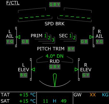
25 EFIS DC Electricity Page Engine Page Fuel Page Hydraulics Page Wheel Page Flight Controls Page 48 (c) 2007 Wilco Publishing


26 This section describes the aircraft systems. Most of them are controlled trough the overhead panel and can be monitored on the various SD pages. You should always keep in mind that this aircraft is based on the dark cockpit philosophy. It means that when no light is on, everything is all right. ECAM CONTROL PANEL The SD EFIS is here to provide information about the aircraft systems. The SD page to display is automatically selected when needed. For example, when the crew starts the APU, the APU page is automatically displayed during the starting sequence. If the crew wants to display a page at any time, the ECAM control panel should be used. It is located on the upper part of the pedestal. It provides one key for each page. If the pilot presses a key, the associated light turns on and the corresponding page is displayed on the SD. To give the control back to the system, the pilot can press the same key again. The light then turns off, which means the system will automatically select the appropriate page when necessary. about the cabin pressurization system. 5. EL/AC : The AC electricity page shows the AC electric circuit. 6. EL/DC : The DC electricity page shows the DC electric circuit. 7. HYD : This page displays the hydraulic system. 8. C/B : The circuit breaker page. 9. APU : This page shows information about the APU. 10. COND : Shows information about air conditioning. 11. DOOR : This page shows the aircraft door status. 12. WHEEL : This page shows the wheel and brake status. 13. F/CTL : The flight control page shows the position of all the flight controls and the flight control computer status. 14. Fuel : TThe fuel page shows the fuel information with all the aircraft fuel tanks. 15. STS : The status page shows the current failure status. ELECTRICITY The electricity circuit can be controlled from the overhead ELEC section. batteries are on (default). The battery voltage is displayed next to each switch. 5. APU battery switch: Like the battery 1 and 2 switches, it is dark when the APU battery is on. 6. Generator switches (1 for each engine). They are dark when in use. They are in fault when the corresponding engine is not running. An OFF white light is visible if a generator is turned off. 7 APU Generator. This switch controls the electric power that comes from the APU. It is on by default. 8. When an external power is available, a green AVAIL light turns on. Two ground power sources are available, EXT A and EXT B.The crew can then press one of these buttons to use this electricity source and ON appears in blue. Batteries This aircraft is equipped with 3 batteries that can provide electricity for a limited time. As soon as an external source is provided, the batteries are charged if necessary. Each battery voltage is displayed on the overhead panel according to the voltage display selector switch. When the aircraft is cold and dark, the batteries should be turned on first, even if a ground power unit is available. When the engines are stopped, the generators are in fault mode because no energy can be provided. When the engines start, make sure the generators are turned on. Ground Power Unit (GPU) When the aircraft is parked on the ground, a ground power unit can be connected to the aircraft to provide electricity without needing to burn any fuel. This is simulated in this aircraft. When you are parked on the ground, with parking brakes set and engines stopped, the ground power unit is available 1 minute after the engines have stopped. The external power (EXT PWR) switch then shows the GPU is available. At this time, the crew can press the EXT PWR switch to use this energy source. A blue ON light then appears on the EXT PWR switch. As soon as the aircraft moves on the ground, the external power becomes unavailable. 1. TO CONFIG : This button is used to check the takeoff configuration prior to departure. It checks some elements of the aircraft configu-ration to make sure everything is OK for takeoff. 2. ENG : The engine page displays information about the engines. 3. BLEED : This page shows information about the air bleed system. 4. PRESS : This page displays information A330: A340: 1. Display selector: This switch determines the voltage value displayed. It can be battery 1, battery 2 or APU battery. 2 - Voltage display screen. 3.4 Battery switches. They are dark when Auxiliary Power Unit (APU) The APU is capable of providing electricity for the aircraft. A specific section is dedicated to the APU later in this chapter. When the aircraft is cold and dark and no ground power unit is available, the APU should be turned on as soon as possible because batteries can only provide electricity for a limited time. Generators The generators provide electricity from the engine rotation. As soon as an engine is started, its generator can be used to provide electricity to the aircraft and the APU and GPU can be turned off. EL/AC Page The AC electric circuits can be monitored through the EL/AC page. 1. Generators associated to the engines. Each white box shows the generator load, the voltage and the frequency (amber XX 50 (c) 2007 Wilco Publishing


27 are shown if the corresponding engine is stopped). 2. APU GEN : This box is visible as soon as the APU is running and the APU GEN switch is on. 3.4.EXT PWR : A and B: These boxes are visible as soon as a GPU source is available and provides electricity. Possible Electric Configurations All the electric sources are configured so that the AC ESS bus has AC electricity. The generators provide energy with the highest priority. In flight, the standard configuration is shown in the following image, with batteries and generators on, APU and GPU off: In case of an engine failure, the associated generator can not provide energy any more. The other engine provides AC current to the whole sytem: If the generators are off or the engines are stopped (when parked on ground for example), the external power source (GPU) has the priority. If it is not available, it is assumed the APU will provide energy, as shown here: If 1 engine is off on the A330, or 2 engines are off on the same side on the A340, the APU can provide energy to the corresponding AC bus, as shown here; As soon as the external power becomes available and is selected by the crew as the energy source, it takes the priority over the APU. The APU source is still available, but not used : Alerts & Warnings Message Color Reason ELEC GEN 1 OFF Amber Generator 1 is off while engine 1 is running ELEC GEN 2 OFF Amber Generator 2 is off while engine 2 is running ELEC GEN 3 OFF Amber Generator 3 is off while engine 3 is running ELEC GEN 4 OFF Amber Generator 4 is off while engine 4 is running EL/DC Page The DC electric circuit can be monitored through the EL/DC page. Each DC bus is energized through the corresponding AC bus through transformers/rectifiers. 1. AC buses (2 on the A330, 4 on the A340), which are the energy source for the DC buses. 2. Transformers rectifiers that transform AC electricity into DC. 3. Batteries. These aircrafts have 3 batteries: battery 1, battery 2 and APU battery. Possible Electric Configurations The DC electric configuration directly depends on the AC configuration, described in the previous section. If the AC buses are properly energized, the DC buses are energized accordingly: If not, the batteries energize the DC buses: Alerts & Warnings Message Color Reason ELEC BAT 1 OFF Amber Battery 1 has been turned off. ELEC BAT 2 OFF Amber Battery 2 has been turned off. HYDRAULICS The hydraulic system is controlled through the HYD section of the overhead panel. This aircraft has 3 independent hydraulic circuits for redundancy, designated Green, Blue and Yellow. A330: A : A : 1. An hydraulic pump is associated with each engine. These switches allow the crew to switch an engine pump off. If an engine is stopped, the corresponding hydraulic pump is in fault mode. 2. In addition, 3 electric pumps can be run to provide hydraulic pressure even if all engines are stopped. In standard configuration,they are off and nothing is lit, according to the dark cockpit philosophy. As soon as an electric pump is turned on, an 'ON' light appears in blue. On the A330, the Blue electric pump is on by default, and on 'OFF' white light appears if it is switched off. 52 (c) 2007 Wilco Publishing


28 HYD Page The hydraulic system can be monitored on the HYD SD page. 1. The 3 hydraulic reservoirs, with an arrow showing the level. 2. The 4 hydraulic pumps. Their status depends on the pump switches located on the overhead panel. 3. Engine references, shown in amber if the corresponding engine is off. 4. The 3 engine pressures, displayed in pound per square inch (PSI). It turns amber if the pressure is too low. 5. Electric pump status. The white triangle appears filled amber if this pump is turned on through the overhead panel. FUEL The fuel system can be controlled through the FUEL overhead section. These aircraft have fuel tanks in the wings, in the center fuselage and in the tail. For each tank section, 2 fuel pumps are available. The fuel system manages the fuel automatically. Fuel is pumped from the center and tail tanks in priority, then inthe wing tanks. A330: 1. Left main pump 1 switch. 2. Left main pump 2 switch. 3. Left standby pump switch. 4. Right main pump 1 switch. 5. Right main pump 2 switch. 6. Right standby pump switch. 7. Wing cross-feed switch. A : The A has 2 main pumps and 2 standby pumps for each wings, in addition to the 2 main center pumps. 1. Left main pump 1 switch. 2. Left main pump 2 switch. 3. Left standby pump 1 switch. 4. Left standby pump 2 switch. 5. Center pump 1 switch. 6. Center pump 2 switch. 7. Right main pump 1 switch. 8. Right main pump 2 switch. 9. Right standby pump 1 switch. 10. Right standby pump 2 switch. A : 1. Left main pump 1 switch 2. Left standby pump 1 switch 3. Left main pump 2 switch 4. Left standby pump 2 switch 5. Center pump 1 switch 6. Center pump 2 switch 7. Right main pump 1 switch 8. Right standby pump 1 switch 9. Right main pump 2 switch 10. Right standby pump 2 switch 11. Left trim pump switch 12. Right trim pump switch According to the dark cockpit philosophy, no switch light is visible when everything is OK, that is when all the fuel pumps are on. Fuel Pump Usage The fuel pumps should always be on. If a fuel tank becomes empty, the corresponding fuel pump automatically stops. This is a normal situation. If the crew turns the center pumps off, the fuel from the center tank can not feed the engines any more. However, if the crew turns the left or right pumps off, the engines can still get fuel by gravity feed. Warning : If the engines are fed by gravity, there is a high risk of engine failure at high altitudes. If the fuel is not pumped out of the tanks, the altitude increases the risk of creating an emulsion that will damage the engines. Manipulating the fuel pumps may be useful to reduce a fuel imbalance. If you have much more fuel in one wing than in the other, you might want to shut off the fuel pumps to the less filled wing and pump fuel to the engines from the other wing. On this aircraft, the maximum fuel imbalance is around 400 kg. FUEL Page The SD FUEL page shows the current fuel configuration.it is different on each aircraft but shows the same kind of information. : A Left main pump 1 status. 2 - Left main pump 2 status. 3 - Center main pump 1 status 4 - Center main pump 2 status 5 - Right main pump 1 status 6 - Right main pump 2 status 7 - Left standby pump status 8 - Right standby pump status 9, 10 - High pressure engine valves 11 - Wing cross feed status 12, 13, 14, 15 - Wing tank fuel quantities 16, 17 - Center and trim tank quantities 18, 19 - Fuel used by each engine since startup 20 - Total fuel used 21 - Fuel tank temperature 22 - Total Fuel on Board A Left main pump 1 status 2 - Left standby pump 1 status 3 - Left main pump 2 status 4 - Left standby pump 2 status 5 - Right main pump 1 status 6 - Right standby pump 1 status 7 - Right main pump 2 status 8 - Right standby pump 2 status 9 - Center pump 1 status 10 - Center pump 2 status 11 - Fuel used by each engine 12 - Total fuel used since startup 13, 14 - Wing tank fuel quantities 15, 16 - Center and trim tank quantities 17 - High pressure valve status 18 - Fuel tank temperature 19 - Total fuel on board 54 (c) 2007 Wilco Publishing
.")


. 8.")
29 A CTR TK FEEDG Green Status message to indicate the fuel is pumped from the center tank only AIR The air system is controlled through the AIR COND overhead section. COND Page The COND page shows the temperature in every part of the aircraft (the cockpit and the 3 cabin sections). If the hot air valve is closed, no more hot air will be provided to heat the aircraft cabin. 1 - Left main pump 1 status 2 - Left standby pump 1 status 3 - Left main pump 2 status 4 - Left standby pump 2 status 5 - Right main pump 1 status 6 - Right standby pump 1 status 7 - Right main pump 2 status 8 - Right standby pump 2 status 9 - Center pump 1 status 10 - Center pump 2 status 11 - Fuel used by each engine 12 - Total fuel used since startup 13, 14 - Wing tank fuel quantities 15, 16 - Center and trim tank quantities 17 - High pressure valve status 18 - Fuel tank temperature 19 - Total fuel on board 20 - Left trim pump status 21 - Right trim pump status Note : The fuel used is reset when the flight is reset through the Reset Flight menu action. Alerts & Warnings Message Color Reason FUEL L WING TK LO LVL Red Left wing fuel tank level is too low FUEL R WING TK LO LVL Red Right wing fuel tank level is too low FUEL L+R WING TK LO LVL Red Total wing fuel tank level is too low FUEL CTR TK PUMPS OFF Amber Center tanks pumps are off while center tank is not empty FUEL GRVTY FUEL FEEDING Red Wing fuel pumps are off so the engines are fed with gravity only A330 A / Pack Flow. It lets the crew select the low, normal or high pack flow. 2.3 Temperature knobs that let the crew adjust the temperature in the cockpit, and the cabin. 4. Hot air valve can be closed using this switch. 5. Pack switches. 6. Engine bleed switches. The engine bleed valves are opened in a standard configuration. Pressing these buttons close them. 7. APU bleed switch. By default, it is closed. The crew must press this button to let the APU provide bleed air (necessary for initial engine start). 8. Cross bleed (useful for restarting an engine in flight, refer to the power plant section for more information). 9. This knob lets the crew select the Crew Heater temperature (A340 only). The status of the air system can be monitored on several SD pages. CAB PRESS Page The cabin pressure page shows the status of the pressurization system. 1. LDG ELEV : This is the elevation of the arrival airport. It is dashed when the arrival airport is not defined. 2. DeltaP : This is the pressure difference between inside and outside the aircraft. 3. Cabin V/S : This shows the vertical speed felt by the cabin (the internal cabin pressure variation). 4. Cabin Altitude : This is the altitude that corresponds to the current cabin pressure. 5. Pack valves, controlled by the pack switches on the overhead panel Inlet, extract and outflow valves. They are automatically controlled. 9. Safety valve. It automatically opens if the delta P is too high, to prevent any aircraft damage. BLEED Page It shows the status of the air bleed system. 1. Pack outlet temperature 2. Pack compressor outlet temperature 3. Pack flow pressure 4. Precooler inlet pressure 5. Precooler outlet temperature 6. Cross bleed valve. If the overhead is AUTO, the cross bleed valve status is the same as the APU bleed valve. Otherwise, it is open or shut according to the XBLEED knob position. 7. APU bleed valve. 8. Engine high-pressure valves 9. Wing anti-ice air bleed (visible only if wing anti-ice is turned on). 10. Engine bleed valves, controlled by the ENG BLEED overhead switches. ANTI-ICE The anti-ice protection system is controlled through the ANTI ICE overhead section. 1. Wing anti-ice. Its status can be monitored on the BLEED page. 2. Engine anti-ice. 56 (c) 2007 Wilco Publishing
 and provides full heating as soon as the aircraft is airborne.")
 It is managed through the APU section of the overhead.")
 and the APU flap is opened to let the air enter into the APU ('FLAP OPEN' message displayed on the APU page).")


30 3. Probe and Window anti-ice. It is fully automatic. It provides low heating when the aircraft is on the ground (to avoid having ground personnel burnt if they touch the probe) and provides full heating as soon as the aircraft is airborne. You can initiate full heating by pressing this button. An 'ON' light then appears. Alerts & Warnings Status messages appear on the E/WD when engine and wing anti-ice are used. Message Color Reason ENG A. ICE Green Engine anti-ice is on WING A. ICE Green Wing anti-ice is on AUXILIARY POWER UNIT (APU) It is managed through the APU section of the overhead. APU Start & Stop To turn the APU on, first press the master switch. The APU system is activated ('ON' blue light appears on the master switch) and the APU flap is opened to let the air enter into the APU ('FLAP OPEN' message displayed on the APU page). The APU page automatically appears on the SD. If fuel is available, the START button can then be pressed, an 'ON' light appears on the button. This launches the APU start sequence. The start sequence can be monitored on the APU page displayed on the SD. When the APU is started, a green 'AVAIL' light replaces the blue 'ON' light on the START switch. An 'AVAIL' message appears on the APU page and an ECAM message displays 'APU AVAIL'. The APU is now ready to provide air and electricity. The APU can be started at any altitude and at any airspeed. The APU fuel consumption is around 100kg per hour. APU Bleed As soon as the APU is running, its air can be used to start the engines. To do this, the crew must press the APU BLEED button in the AIR COND overhead section (see the Air section for more details). Note : If you are in Beginner mode, the APU is not necessary to start the engines. APU Page The APU page appears automatically on the SD during the APU start sequence. The crew can also access this page by pressing the APU button on the ECAM control panel. 1. AVAIL message appears as soon as the APU start sequence is finished and the APU is available. 2. FLAP OPEN message is displayed as soon as the APU system is turned on and the APU flap is opened to let air in. 3. This white box displays the APU electric information : load, voltage and frequency. The box disappears if the APU is not available. The green arrow on top of the box disappears if the APU GEN is turned off on the overhead. 4. This box shows the APU bleed information, with the air bleed pressure. Amber XX is displayed if the air bleed is not available. 5. Bleed air valve; controlled by the APU BLEED switch on the overhead. 6. APU rotation speed. 7. APU Exhaust Gas Temperature (EGT). Alerts & Warnings Status messages appear on the E/WD when the APU is used. Message Color Reason APU AVAIL Green The APU is up and running APU BLEED Green The APU is available and the bleed valve is open POWER PLANTS The engines are managed by the Full Authority Digital Engine Control (FADEC). This device controls the engine during the start sequence and during the flight to provide optimal usage. Engine Monitoring Engine status is monitored through the Engine/Warning Display (E/WD), which displays essential engine and FADEC information. Information is also available through the Engine and Cruise page of the SD. Depending on the engine type, the E/WD can have different layouts. Refer to the EFIS section for more details. Anyway, the most important engine information is always displayed on the E/WD. On these examples, N1, EGT, N2 and EPR (for EPR-driven engines) are displayed. In addition, FADEC information is displayed: the mode, which depends on the thrust lever detent, and the max N1 (or EPR) that depends on this mode. In addition, engine information is displayed on the ENG page : 1. Fuel used by each engine since last startup. 2. Oil quantity, in quarts 3. Oil pressure, in Pound per Square Inch (PSI) 4. Oil temperature 5. Vibration on the first compressor stage 6. Vibration on the second compressor stage The engine page is automatically displayed during engine start sequence. It can be displayed at any time by pressing the ENG key on the ECAM control panel. During the cruise, the CRUISE page is automatically displayed on the SD. It shows important information about the engines and the cabin pressurization and temperature, as shown on the ENG and PRESS pages : 58 (c) 2007 Wilco Publishing


. This switch position can also be used when the engines are running in case of heavy rain.")

31 1. Fuel Used by each engine, as shown on the engine page 2. Oil quantity (in quarts), as shown on the engine page 3. Vibrations Cabin DeltaP, vertical speed and altitude, as shown on the PRESS page 7. Cabin and cockpit temperature, as shown on the COND page. Note that this page can not be selected manually. It appears automatically on the SD as soon as the aircraft is above the transition altitude. Engine Start & Stop on Ground When the aircraft is parked on the ground and engines have to be started, the APU must be started first in order to provide air bleed necessary for the engine start sequence. Refer to the APU section for more information about APU start and APU bleed. When the APU is started and APU bleed is on, the engine start is managed through the ENG section located on the pedestal, just below the thrust levers : 1. Engine Master Switches 2. Engine mode switch. To start the engine, the engine mode switch must be placed on the IGN/START position. This operation turns on the engine igniters and the FADEC (the E/WD engine information become active). This switch position can also be used when the engines are running in case of heavy rain. It provides continuous ignition, and it reduces the risk of having an engine stop. The engine master switches can then be used to initiate the engine start sequence. The crew just has to move each engine master switch up and the FADEC does the rest to start the corresponding engine. On the twin-engine aircrafts, both engines can not be started simultaneously because the APU does not provide enough air for 2 engines. Usually, engine 2 is started first. This is because it provides hydraulic pressure to the Yellow circuit, the one used by the brakes. If for any reason the pilot needs to use the brakes in an emergency, having the Yellow circuit under pressure is safer. Start engine 2 by using the left mouse button to move the ENG 2 master switch up. You can monitor the start sequence via the E/WD and on the SD ENG page that automatically appears. As soon as engine 2 has started, you can start engine 1 by moving the ENG 1 master switch up. When engine 1 is started, you should return the engine mode switch to the NORM position. The only difference on the A340 is the fact that the APU is powerful enough to let you start 2 engines at the same time. The procedure consists in starting the 2 engines of the same side simultaneously. Note : If you are in Beginner mode, you can just press Ctrl-E to start the engines, without needing to start the APU. This function is inhibited in Intermediate and Expert modes. To stop the engines, the pilot just has to move down each engine master switch. The crew should make sure the APU is running before stopping all engines because generators will stop providing electric energy. Engine Master Switch Usage in FS : To move the engine master switches down (engine off), you must use the right mouse button and click the lower part of the switch. This was done to prevent an unintentional engine stop with a mouse click. Restarting Engine in Flight If an engine must be restarted in flight, the crew can take advantage of the air bleed from the engine that is still running. To do this, the cross bleed valve must be opened by setting the XBLEED switch on the OPEN position (overhead, AIR COND section). Air bleed is then available and the pilot can use the engine mode switch and engine master switch to start the engine as explained in the previous paragraph. INERTIAL REFERENCE SYSTEM (IRS) The Inertial Reference System (IRS) provides the aircraft position. To work properly, the system must be aligned. The IRS measures the aircraft accelerations and updates the aircraft position, based on the original position used during alignment. IRS Alignment The IRS are aligned through the INIT A page of the MCDU (refer to the section for more information about this page). As soon as the FROM/TO airports are entered in the MCDU, the IRS can be aligned with the departure airport as the original destination. The IRS can detect if the departure airport position is significantly different from the actual aircraft location. This can happen if the crew makes an error when entering the FROM/TO airport information. In this case, an error message is displayed on the MCDU. The crew should remember that the IRS alignment position taken into account when aligning the IRS is the departure airport reference location stored in the database. This is different from the actual aircraft position. In practice, you don't need to adjust the IRS position before aligning. This is because this aircraft is equipped with a GPS system that will do this automatically when the takeoff thrust is applied. It means the crew should not use the navigation display when taxiing because the IRS may not be perfectly aligned at this time. IRS Unit This device is located on the upper part of the overhead panel Mode selector : For each IRS, a switch lets the crew select the mode used for each IRS : OFF : the IRS is turned off and requires a new alignment before being used again. NAV : all the IRS and air data information are used for navigation. ATT : only the air data information is used for navigation. IRS usage with Flight Simulator : 1. The IRS alignment time is configurable through the aircraft configuration window (refer to the setup section for more information). In the real aircraft, a full IRS alignment takes 10 minutes. Alerts & Warning While the IRS are aligning, a green information message IRS IN ALIGN appears on the E/WD, indicating the remaining time 60 (c) 2007 Wilco Publishing

 Two Radio Management Panels are located on the pedestal. One is available for the captain and one for the first officer.")

32 for alignment. This message turns amber if the engines are started to indicate that the aircraft should not move during the IRS alignment phase. RADIO Standard operation of the radio equipment involves use of the MCDU for radio navigation (in fact, the crew rarely interact with the radio navigation settings because the is in charge of auto-tuning the VOR and ILS). The radio management panels are used for voice radio. Nevertheless, the Radio Management Panels can be used for radio-navigation settings in case of an failure. Radio Management Panels (RMP) Two Radio Management Panels are located on the pedestal. One is available for the captain and one for the first officer. The Captain's RMP can be used to set VOR1 and the FO's RMP for the VOR2. 1. Active frequency window shows the current frequency used for the selected radio. 2. Standby/Course window shows the standby frequency for the selected radio. In case of a VOR/ILS setting, this window is also used to set the VOR/ILS course. 3. Swap button is used to swap active and standby frequencies Selection pushbuttons for the VHF radio channels. 6. NAV pushbutton must be pressed if the crew wants to use the RMP for radionavigation setting, which is not the standard procedure. If this button is depressed, the RAD NAV page of the MCDU is blocked (see the section for more information) VOR and ILS selection pushbuttons. Remember that the left RMP adjusts VOR1 and right RMP adjusts VOR2. 9. ADF selection pushbutton. 10. ADF frequency oscillator switch. 11. Radio master switch. 12. Frequency/Course knob : The outside knob sets the integer part and the inner knob sets the decimal part of the standby frequency. In case of a course setting, the outer knob changes the course value by 10 degrees and the inner knob by 1 degree. In order to use an RMP to set a VOR or ILS, the NAV pushbutton must be pressed first to activate the NAV pushbuttons (7, 8, 9, 10). As soon as this is done, the can not be used to set the radio any more. The crew can then set the VOR/ILS standby frequency using the frequency/course knob (12). When the swap button is pressed to swap the frequencies, the standby window (2) changes and displays the VOR/ILS course, which can be changed at this time using the frequency/course knob. After a few seconds, the display turns back to standby frequency. RMP usage in Flight Simulator : Remember that the VHF1 and VHF2 buttons of the RMP correspond to the COM1 and COM2 radio channels of Flight Simulator. Audio Management Panel (AMP) The audio management panel lets the crew select the radio channels heard on the cockpit loud speakers. Each pushbutton lets the crew activate/ deactivate the audio for each radio channel : 1.2. VHF1 and VHF2 channels (called COM1 and COM2 in Flight Simulator) 3.4. OR1 and VOR2 channels 5. Marker channel (inner, middle and outer markers) 6. ILS channel. Because of an FS limitation, ILS channel is linked to the VOR1 channel. 7. ADF channel. TRANSPONDER & TCAS The transponder & TCAS device is located on the pedestal. It allows the crew to enter the transponder code required by the ATC to identify the aircraft and to configure the TCAS. 1. Transponder Mode 2. Transponder Channel 3. TCAS Master Switch 4. Keypad for the transponder code entry 5. TCAS Mode THRT : Only the dangerous intruders are shown on the ND, within a +/ ft altitude range ALL : Intruders located within +/ ft are shown on the ND ABV : Intruders located within / ft are shown on the ND BLW : Intruders located within / ft are shown on the ND 6. TCAS Advisory mode STDBY : The intruders are shown on the ND according to the TCAS mode, but no advisory. TA : When an intruder is close to the aircraft with a potential collision trajectory, an aural warning 'TRAFFIC' is triggered. TA/RA : When an intruder is very close to the aircraft with a potential collision trajectory, an aural warning and a resolution advisory is provided. Transponder Usage To enter a transponder code, the transponder should obviously be turned on. Then any action on the keypad clears the existing code to enter a new one. Pressing the CLR key erases the code being entered. The code entry is validated as soon as the 4 digits have been entered. TCAS Usage The only important thing to think about is to change the TCAS mode according to the flight phase : ABV mode should be set prior to takeoff to monitor potential intruders above the aircraft during the takeoff and climb phases. BLW mode should be engaged just before the descent is initiated to monitor the potential intruders below the aircraft. GROUND PROXIMITY WARNING SYSTEM (GPWS) The GPWS provides aural alerts to indicate potential danger related to the ground proximity, such as excessive descent rate or bad aircraft configuration. The GPWS is controlled through the switches located in the GPWS section of the overhead panel. These switches let you turn off all or some of the GPWS warnings. 1. TERR : The terrain proximity alerts are inhibited. 2. SYS : The whole GPWS is turned off 3. G/S MODE : The glideslope alert is inhibited. 4. FLAP MODE : The landing aircraft configuration warning is inhibited. Alerts & Warning Message Color Reason GPWS SYS MODE OFF Green The GPWS is totally off GPWS FLAP MODE OFF Green The flap mode is off GPWS G/S MODE OFF Green Glideslope mode is off 62 (c) 2007 Wilco Publishing


33 FLIGHT CONTROLS Sidesticks & Rudder Pedals There is not much to say about flight controls as they were described in detail in the Fly-by- Wire section. The only thing to keep in mind is that a strong action on the stick or on the rudder pedals disconnects the autopilot. As this is not the standard procedure, it triggers an alarm that can be stopped by pressing the A/P disconnection button. Flight Control Computers Five computers are in charge of the Fly-by- Wire system: 3 primaries and 2 secundaries. All these computers can be turned off using the switches located in the 2 FLT CTL sections of the overhead. These switches are supposed to be used in case of failure, to reset the flight control computers by turning them off and back on. They are not designed to turn these computers off. The primary computer are in charge of the flight envelope protection, the auto-trim system and the auto-coordination. If they are turned off, amber crosses appear on the PFD to indicate there is no flight envelope protection: no bank angle limit and no pitch angle limit. Auto-coordination in Flight Simulator : When you load this aircraft in Flight Simulator, the FS auto-coordination is turned on according to the primaru computer status. When the aircraft is unloaded from FS, the previous auto-coordination status is restored. Speed Brakes & Ground Spoilers Speed brakes and ground spoilers are different, even if they are controlled through the same handle and use the same aircraft parts. The speed brakes can be deployed in flight, they use 4 of the 5 moving panels on the top of the wings and their movement is limited to approximately 50% of the maximum deployment. The role of the speed brakes is to reduce the lift and increase the drag to decelerate the aircraft in flight. If they are deployed, a green message 'SPPED BRK' is displayed on the E/WD. The ground spoilers can be deployed on the ground only. They are used to reduce the aircraft speed and to break the lift for optimal break efficiency. When they are activated, all the 5 panels deploy at their maximum angle. The ground spoilers can be armed to deploy automatically during takeoff in case of a rejected takeoff or during approach to deploy when the aircraft touches the ground upon landing. When they are armed, a green message GND SPOILERS ARMED is displayed on the E/WD. When the ground spoilers have automatically deployed, the action of disarming them will make them retract. The upper and lower parts of the handle can be clicked to move the handle up and down. Moving the handle higher than the RET position (retracted) arms the ground spoilers. Moving the handle down deploys the speed brakes progressively. Speed Brake/Ground Spoiler control in Flight Simulator : The standard FS keys can be used to arm/disarm the ground spoilers and extend/retract the speed brakes. By default, the / key is used to extend/retract the speed brakes and Shift-/ is used to arm/disarm the spoilers. Flaps The flaps have specificity on this aircraft: the flap handle has 4 positions while the flaps and slats can have 6 positions, as shown in the following table : Flap/Handle Flap/Slat Usage A330 A340 A340 Position Position Max spd Flight Vmo 1 1 Approach or Takeoff/ 1+F Landing Takeoff/ Landing 3 3 Takeoff/ Landing FULL FULL Landing The table also shows how the different flap/slat configurations are to be used, and the maximum airspeed for each configuration. The table shows 2 flap/slat positions correspond to the same handle position. If the handle is moved to the 1 position, the flap/slat position is set according to the following diagram : The flap/slat position can be monitored on the E/WD. Refer to the EFIS section for more information. Trims Elevator Trim This aircraft is equipped with an auto-trim system managed by the fly-by-wire system. It means the crew is not supposed to interact with the elevator trim wheels located on the left and right of the thrust levers, except in case of a failure. Note that any manual action on the elevator trim disconnects the AP with an alarm. GEAR, WHEELS & BRAKES Landing Gear The landing gear is controlled through the gear lever located on the main panel. If the aircraft gets close to the ground during descent and the gear is still retract, a alert 'L/G Gear Not Down' appears on the E/WD with an aural warning. In addition, a red arrow light is illuminated adjacent to the gear lever. The landing gear status can be monitored on the SD (WHEEL page) and on the LDG GEAR section of the main panel. The lighted symbols indicate each landing gear status : Green Triangle : The landing gear is down and locked Red UNLK : The landing gear is currently unlocked (in transition) Nothing : The landing gear is retracted. The only difference on the A340 is the additional indicator for the center landing gear located under the aircraft belly. Autobrake system The autobrake system is dedicated to manage aircraft brakes automatically when the takeoff is rejected or when the aircraft lands. 64 (c) 2007 Wilco Publishing
. The MAX position must be used for takeoff only. For landing, MED should be used if the runway is short or wet, otherwise LOW should be used.")


34 A330 and A A A330 and A : The autobrake system has 3 positions : LOW / MED : Low/Medium braking pressure, can be used for landing MAX : Maximum braking pressure, to be used for takeoff only in case of RTO (rejected takeoff). The MAX position must be used for takeoff only. For landing, MED should be used if the runway is short or wet, otherwise LOW should be used. When the autobrake is actually active to decelerate the aircraft, a green light 'DECEL' appears above the selected autobrake button. the brake temperature. If the brake temperature is too high when the takeoff check is operated, an alert HOT BRAKES is triggered. The crew must be aware that heat in the brakes makes them less efficient. The parking brake status appears on the E/WD : PARK BRK appears in green when parking brake is set. PARK BRK turns to amber if the parking brakes are set while engine power is greater than idle. The value is shown in green if the temperature is normal. In turns amber over 300 C. A green arc appears over the hottest wheel when the brake temperature is between 100 C and 300 C. An amber arc appears over the hottest wheel when its brake temperature is above 300 C. 4. Brake status 5. Ground spoiler status : vertical arrows appear when they are deployed. LIGHTING & SIGNS External Lights The aircraft lights are controlled through the EXT LT section of the overhead panel. on just before the aircraft moves on the ground. This is the best way for ground personnel to see the aircraft is cleared for taxi. It must be turned off when the landing gear is retracted, even if it is automatically turned off if the gear is up. When the landing lights are on, a green message LDG LT appears on the E/WD. If strobe lights are off when the aircraft is airborne, a warning message STROBE LT OFF appears on the E/WD. Panel Lighting At night, the lighting equipment provides panel lighting. The panel lighting is turned on using the standard FS key for panel lights (Shift-L by default). Turning the panel lighting on during the day has no visible effect. At night, the panel lighting looks as shown here: A : The autobrake system is controlled through a knob and a pushbutton. 1 - The TO pushbutton is used for take off to engage the RTO setting (Rejected Take Off) that will give maximum braking power is the take off is aborted. 2 - The knob lets you select the autobrake setting for landing with more precision than on the A330 and A You have 6 autobrake settings, from OFF (no autobrake) to HI (maximum braking power for landing). If the autobrake is engaged, its status is displayed on the E/WD. Pressing the button of the currently selected position disarms the autobrake. When autobrake is switched off, a flashing message AUTOBRK OFF appears for 10 seconds on the WHEEL page. Brakes and Parking Brakes The brake status can be monitored on the ECAM Wheel page, detailed later in this section. The most important information is WHEEL Page The WHEEL page is automatically displayed on the SD when the aircraft is on the ground with engines started. It can also be selected by pressing the WHEEL key on the ECAM control panel. These images show the A330 and A340 wheel pages. The only difference is the additional wheel of the A340, located under the belly of the aircraft. This additional wheel has no brake. 1. Nose, left, right and center wheel status These indicators show the gear status. The lines represent the gear doors. They are green when the gear doors are closed, amber when the doors are open or moving. The triangles represent the landing gears. They are green if the landing gears are down and locked and red if the gears are in transition. No triangle is displayed if the gears are retracted. 2. Gear tire pressure, in PSI 3. Brakes temperatures: 1. Strobe lights : They should be on when the aircraft is in flight. They can be turned on, off or set in AUTO mode. If set to AUTO, they automatically turn on when the aircraft is airborne, and turn off when the aircraft is on the ground. 2. Beacon lights : Red lights located above and below the aircraft. They should be switched on as soon as the engines are running or the aircraft moves. 3. Wing lights : These lights should be used to taxi to the gate. They can be turned off when the engines are stopped. 4. Nav lights should be turned on as soon as the aircraft is energized. 5. Runway turn off lights are designed to be used with the taxi lights during taxi. 6. Landing lights : These lights are big and can be retracted into the aircraft belly. They should be turned on as soon as the aircraft is cleared to align on the runway for takeoff and can be turned off when passing feet. 7. Nose lights (or Taxi lights) must be turned In addition, the panel lighting provides flood lighting that can be activated using the FLOOD LT MAIN PNL knob on the pedestal. The Ctrl-Shift-F key can also be used to turn flood lighting on/off. With flood lighting, the main panel looks like this: Keep in mind the EFIS brightness can be adjusted using the mouse wheel when the mouse is in the 66 (c) 2007 Wilco Publishing
35 EFIS central zone. This is very useful at night. Seat Belts & No Smoking The Seat Belt & No Smoking signs are controlled with the switches located on the SIGNS section of the overhead panel. Each switch has 3 positions : ON, OFF and AUTO. In AUTO mode, the seat belt sign turns on when the aircraft moves and turns off when the aircraft crosses feet in climb. It turns back on when the aircraft reaches feet in descent, and turns off again when the aircraft is landed and the engines are stopped. In AUTO mode, the no smoking signs always turns on because all the flight today are nonsmoking flights. The status of the seat belt and no smoking signs is displayed in green on the E/WD. PREAMBLE The Flight Management System is composed of the Flight Management and Guidance Computer () and the Multifunction Control and Display Unit (MCDU). The MCDU is the device used by the pilot as an interface between him and the. It computes all kind of data to fly the aircraft safely along its trajectory. During cockpit preparation, the MCDU is used to insert a route, from departure to destination. The computes vertical and speed profiles according to the ATC constraints and the aircraft performance. The interacts with the flight directors, the autopilots and the autothrust system to guide the aircraft, taking account of any parameterf the pilot decides to manually select (speed, V/S, heading, ). During the flight, the MCDU displays data computed by the, such as Estimated Time of Arrival (ETA), fuel predictions, constraint management... PHASES & FLIGHT PHASES The manages several phases during the flight. They are described in the following table: PREFLIGHT When the aircraft is on the ground, prior to take off power. TAKE OFF When take off power is applied (FLEX or TOGA) and the aircraft is below 1500 feet AGL. CLIMB From 1500 feet to the cruise altitude CRUISE All along the cruise DESCENT During the descent from the cruise altitude APPROACH Final part of the descent, close to the destination. GO AROUND If TOGA power is applied before landing DONE When the flight is finished and the aircraft has landed. The also divides the flight into several phases, used for the system internal use and for the alert management: MCDU USAGE The MCDU is composed of - 12 line select keys, 6 one the left (referenced 1L to 6L) and 6 on the right (1R to 6R). - The page keys that give direct access to some predefined pages, - The alpha and numeric keypads to enter data into the MCDU - The brightness control knob to modify the display brightness. To enter any data into the MCDU, you can use the keypads. All the characters typed in are displayed on the bottom line of the screen, called the scratchpad. When the data is typed, you click the line select key to enter it where you require. Some lines contain two values, separated by a / (slash). In this case, you can enter the 2 values by separating them with a slash. If you want to enter the first value only, enter it directly. If you want to enter the second value only, precede it with a slash. The time information is displayed using a XXYY format, where XX are the hours and YY are the minutes. For example, 0120 means 1 hour 20 minutes. Entering time information into the MCDU must use the same convention, where XX can be omitted if null. Keypad simulation in FS: 68 (c) 2007 Wilco Publishing

 to simulate the 12 line select keys (F1 to F6 for 1L to 6L, F7 to F12 for 1R to 6R).")
 is used to enter data in the MCDU, the following keys simulate the page keys: PC keyboard key Ctrl-D Ctrl-O Ctrl-P Ctrl-A Ctrl-N Ctrl-R Ctrl-U Ctrl-M Ctrl-Pg")
36 You can use the keypad by clicking any key in the keypad with the mouse. It may be painful if you have a lot of data to enter. This is why you can also use your PC keyboard, using the keys in combination with a modifier or a locker, to enter data in the MCDU scratchpad. Refer to the Setup section for more information about the possible keyboard configuration. You can also use the function keys (F1 to F12) to simulate the 12 line select keys (F1 to F6 for 1L to 6L, F7 to F12 for 1R to 6R). The Scroll Lock key is the default locker, which means that if you press this key, any key typed on your keyboard will be directed to the MCDU. Refer to the Setup section for more information. When a locker key (such as Scroll Lock) is used to enter data in the MCDU, the following keys simulate the page keys: PC keyboard key Ctrl-D Ctrl-O Ctrl-P Ctrl-A Ctrl-N Ctrl-R Ctrl-U Ctrl-M Ctrl-Pg Down Ctrl-Up Arrow Ctrl-Down Arrow MCDU page key DIR PROG PERF DATA F-PLAN RAD NAV FUEL PRED MCDU MENU NEXT PAGE Up Arrow Down Arrow The MCDU displays information on pages. When a page content can not be displayed on single page, the pilot has to use specific keys to display the rest of the information: - If the page can not display the whole information on the 6 select key lines, the pilot can scroll the page using the 2 vertical arrow keys. On the bottom right corner, vertical arrow symbols show if the page can be scrolled upward, downward, or both. - If the information is displayed on several different pages, a horizontal arrow on the top left corner shows that another page exists. Pressing the NEXT PAGE key shows the next page. A vertical arrow in the bottom right corner shows the page can be scrolled upward. A left arrow in the top right corner shows a next page exist. Press NEXT PAGE to display it. CHARACTERS AND COLORS The colors and the type of characters used to display information is important as they respect a convention that helps the pilot in understanding each information type. DATA TYPE > COLOR & CHARACTERS Page title, comments, sratchpad > White, normal characters Modifiable / Selectable data > Blue Mandatory data entry > Amber boxes Optional data entry > Blue brackets Non modifiable data > Green Computed data > Small characters Constraints> Magenta Data that impacts the flight plan > Followed by a * Primary flight plan > Green Next flight plan waypoint > White Temporary flight plan > Yellow Secondary flight plan > White Features that don t exist in the real aircraft (used for simulation only) > Grey ASSISTANCE For some MCDU data, you may request assistance. If you don t know a value that should be entered in an MCDU field, you can ask FS to assist you, and if FS knows the value, it will be provided to you. To request assistance, just click on the select line with an empty scratchpad, and FS will fill the scratchpad with the value it has, if available. For example, the pilot is supposed to enter the aircraft Zero Fuel Weight (ZFW) in the 1R line of the INIT B page. If you don t know this value, make sure the scratchpad is empty and click the 1R button. The scratchpad is then filled with the ZFW value provided by FS. You just have to click on the 1R button again to enter this value. ³ Note that the assistance is never available if you are in Expert mode. MCDU MENU PAGE The MENU page is accessed by pressing the MAIN MENU page key. It shows the various systems the pilot can access through the MCDU. The screen shows the name of the selected system in green, all others in white. System simulation in FS: Only the option is valid in FS. The ACARS and AIDS are not implemented at this time. INIT A PAGE This page can be accessed by pressing the INIT page key or by clicking the 1L key of the MENU page. It is accessible only during the PREFLIGHT phase. Note that a right arrow is visible in the top right corner because the INIT B page can be accessed from this page by pressing the NEXT 70 (c) 2007 Wilco Publishing
 At the MCDU initialization, this field is shown with amber boxes, which means it is mandatory. The pilot can enter a company route name in this field.")
37 PAGE key of the MCDU. INIT A page when no information has been entered. INIT A page when all the necessary information has been entered. CO RTE (1L) At the MCDU initialization, this field is shown with amber boxes, which means it is mandatory. The pilot can enter a company route name in this field. If the route exists in the database, it is loaded in the. Note that a route is composed of a departure airport, an arrival airport and waypoints. It does not define the departure and arrival runways, or the departure and arrival procedures (SID/STAR). When a route is loaded, a discontinuity is created after the departure airport and before the arrival airport. If the pilot enters a departure and arrival airport in the FROM/TO field, the CO RTE becomes optional (shown with blue brackets), unless a company route has been selected in the route selection page. FROM/TO (1R) When the MCDU is initialized, the field is mandatory. If a company route is selected, this field is automatically filled with the departure/arrival airport of the route. If you enter a departure/arrival airport in this field, the ROUTE SELECTION page automatically appears to let you select a route between the departure and arrival points, if indeed any route exists. If you select a route, it automatically fills the CO RTE field (1L). If no route exists, it just displays "NONE". As soon as the FROM/TO field is filled, the 4L and 4R select lines (LAT and LONG) are filled with the departure airport coordinates. The 3R line (ALIGN IRS) becomes active to establish an IRS alignment, based on these coordinates. ALTN RTE (2L) This field is dedicated to the alternate route. You can enter any data in this field. The alternate route is not implemented in this version. ALTN (2R) This field lets you enter the alternate destination. It is not simulated in this version. FLT NBR (3L) The current flight number must be entered in this mandatory field. Assistance is available for this value. ALIGN IRS (3R) As soon as a Lat/Long position is defined (4L and 4R), this field appears to let the crew align the IRS (Inertial Reference System) according to this position. If no position is defined, this field is empty. LAT and LONG (4L and 4R) These fields show the position (in latitude/longitude), as soon as the departure airport is defined. When the crew fills the FROM/TO field (1R), the lat/long fields are automatically filled with the departure airport position. At this time, you can see vertical arrows (next to LAT), which means you can adjust the latitude by pressing the MCDU vertical arrow keys. You can press the 4R select key to move the arrows next to the longitude field, thus letting you adjust the longitude with the MCDU arrow keys. When the LAT and LONG fields are defined or modified, you can press the 3R select key to align the IRS according to this position. Note: When you enter the FROM/TO airports, the position is initialized with the position of the departure airport, which is not the exact position of the aircraft. You don t have to adjust the aircraft position accurately because this aircraft is equipped with a GPS that will align the IRS accurately when take off power will be applied. COST INDEX (5L) This value is very important for the performance and prediction calculations. It determines how you want to use the aircraft. You can decide to fly at low speed with low fuel consumption, or to fly fast and burn more fuel. Enter a cost index value of 0 corresponds to the lowest possible fuel consumption at low speed (long range), and a higher value corresponds to higher speed, with higher fuel consumption. The cost index can vary from 0 to 999. WIND (5R) This will bring the WIND page that lets the crew define the winds along the flight plan. It will be described later. CRZ FL/TEMP (6L) The crew can define the cruise altitude in this field, and the temperature at the cruise altitude if you wish. The altitude can be entered in feet, or in flight level. If you want to enter an altitue in flight level, you can enter it directly or enter it by preceding it with FL. Value entered Cruise Altitude feet FL330 FL330 (33000 feet AMSL) 350 FL350 (35000 feet AMSL) You can also enter the cruise altitude temperature. If you enter both cruise altitude and temperature, you must use a / as a separator. If you don t enter the temperature, it is automatically calculated when the cruise altitude is entered (in this case, it appears in small characters). Entering the cruise altitude is very important for the performance calculations and for the flight phase sequencing. If you forget to enter this data, some features of the may not work properly. TROPO (6R) The crew can define the altitude of the tropopause, which is feet by default. INIT B PAGE This page is only accessible from the INIT A page by pressing the NEXT PAGE key. It is not accessible if the engines are started. Pressing the NEXT PAGE key again brings back the INIT A page. If you start the engines while the INIT B page is displayed, it jumps to the FUEL PRED page. Note that all the weights on this page are shown in tonnes or in 1000 LBS, depending on the unit system that has been selected in the configuration window (metric or imperial system). TAXI (1L) This field shows the fuel quantity for taxi. The default value (shown in small characters) is 72 (c) 2007 Wilco Publishing
38 200 kg. TRIP/TIME (2L) This field shows the trip fuel and the trip time that are calculated by the when the predictions are available. It is not modifiable by the crew (green). RTE RSV/% (3L) This field displays the route reserve and the corresponding percentage of the trip fuel. By default, it represents 5% of the trip fuel. The crew can modify one of the values, and the computes the other. ALTN/TIME (4L) This field shows the alternate trip fuel and time that are calculated when the predictions are available. It is not modifiable by the crew. FINAL/TIME (5L) This field shows the fuel quantity and time to fly to the alternate airport or to the destination airport if no alternate is defined. The crew can modify one of the values, and the computes the other. Note: The time is displayed and should be inserted using a XXYY format, where XX are the hours and YY are the minutes. For example, 0120 means 1 hour 20 minutes. EXTRA/TIME (6L) This field shows the extra fuel quantity and the available time for holding over the destination or alternate airport. It is calculated by the and is not modifiable by the crew. ZFCG/ZFW (1R) This field shows the Zero Fuel Center of Gravity (ZFCG) and the Zero Fuel Weight (ZFW). This entry is mandatory for the to compute the Gross Weight (GW), which is necessary to determine reference speeds. i Assistance is available for this field. BLOCK (2R) This is the block fuel quantity (quantity of fuel available on board when initializing the ). It is mandatory to compute the Gross Weight (GW) and the fuel predictions. i Assistance is available for this field. > Entering the ZFW and the Block Fuel is very important to let the calculate the Gross Weight (GW). The GW is necessary to determine many data items by the, including the predictions. If you forget to enter this data, predictions are not available and some features may become inoperative. TOW (4R) This field displays the Take Off Weight (TOW), which is calculated by the when the ZFW and Block fuel fields are filled. It is not modifiable by the crew. LW (5R) This is the predicted Landing Weight. It is calculated by the when predictions are available and is not modifiable by the crew. ROUTE SELECTION PAGE This page is only accessible when the FROM/TO field has been filled in the INIT A page. The route selection page displays all the database routes that exist with the FROM/TO airports that were defined in the INIT A page. If several routes exist, you can see them by pressing the NEXT PAGE key of the MCDU. If no route exists in the database for the departure and arrival airports that were defined, NONE is displayed on the route selection page. No route exists between LFRS and LFMN. The route selection page displays NONE, and you just have to press RETURN (6L) to continue. A route exists between LFRS and LFPO. You can use it by pressing INSERT (6R), or ignore it by pressing RETURN (6L). If a route is defined, you can press INSERT (6R) to use it. Note that a database route is supposed to be used as a base for the flight plan, is not a complete flight plan itself. It is composed of a departure and an arrival airport, and waypoints that define the route using airways or direct. A database route does not contain the departure and arrival runway, and does not contain the departure and arrival procedures (SID and STAR). When a route is inserted to create a flight plan, a flight plan discontinuity exists between the departure airport and the first waypoint, and another one between the last waypoint and the arrival airport. Managing these discontinuities will be explained in the flight plan section. WIND PAGE This page is accessible from the INIT A page by pressing the 5R select key. It lets the crew define the winds at different altitudes. When it is displayed for the first time, it displays the history winds. These are the winds recorded by the during the previous flight. This is very useful if you fly the same route back and forth. For example, if you fly from Paris Orly to Nice Cote d Azur, there is a very high probability that you have the same winds if you fly back from Nice to Paris one hour later. As soon as you modify or enter wind information, the HISTORY WIND page becomes the WIND page. The History Wind page shows the winds that were recorded during the previous flight (small characters). We can see that the previous flight didn t reach the FL330, which is why the wind is not defined for the cruise altitude. The wind has been defined for the FL330 (big characters). Consequently, the page became the Wind page. Wind Information (1L to 4L) You can enter wind information at any altitude by entering the wind direction and the wind velocity (in knots), separated by a /. INSERT (6R) Pressing the 6R select key validates the wind 74 (c) 2007 Wilco Publishing
39 information and enters it into the, which will take this information into account for the future predictions. Note the * characters, which means the wind insertion may have an impact on the flight plan. FLIGHT PLAN PAGE The flight plan page is accessible by pressing the F-PLAN key on the MCDU. Basically, the flight plan page displays the flight plan stored in the memory. It also gives access to the lateral and vertical revision pages. Example of a flight plan where the predictions have not been computed. Example of a flight plan with predictions. The layout of the flight plan page is explained here: 1 The flight number is displayed in the top right corner, if it was entered in the INIT A page. Left Column: 2 The FROM waypoint is the waypoint from where the aircraft comes. It is the origin waypoint of the active leg. 3 Name of the airway. In this example, the airway name is automatically generated with the course to fly from the departure airport to the initial waypoint computed by the. 4 NEXT Waypoint: This is the waypoint to which the aircraft is currently flying. It is written with white characters. 5 Overfly symbol: When this symbol is drawn near a waypoint, this waypoint will be overflown. If you want to have a waypoint overflown, press the OVFY key on the MCDU. A white triangle then appears on the scratchpad and you can select a waypoint to make it overfly. Center Column: 6 TIME: This column indicates the time to fly to each waypoint. On this example, no time is displayed because the predictions are not available yet. If an Estimated Time of Departure (ETD) is entered, the UTC time is displayed instead of the time. 7 Bearing to fly from the FROM to the NEXT waypoint. 8 Track to fly from the NEXT waypoint to the following waypoint. If you scroll the flight plan, the BRG and TRK are always displayed between the first and second waypoint displayed on the page. Right Column: 9 Predicted speed (in knots or in Mach) or speed constraint at each waypoint. In this example, speed predictions are not available. The speed prediction is displayed in green, the constraints are in magenta. 10 Altitude prediction/constraint. The altitude prediction is displayed in green, the constraints are in magenta. 11 The distance between two consecutive waypoints is displayed here. Bottom Line: The bottom line shows all the information about the destination. 12 Name of the destination airport. 13 Total flight time, if predictions are available. If an ETD is defined, the predicted arrival time (UTC) is displayed. 14 Distance to destination. 15 Estimated fuel on board (EFOB) at destination. LATERAL REVISION PAGE It is accessible by pressing a MCDU button on the left of any waypoint displayed in the flight plan list. Depending on the type of the waypoint, the LAT REV page has different aspects. LAT REV page at the departure airport. LAT REV page at a normal waypoint. LAT REV page at the arrival airport. DEPARTURE (1L) This is available for the departure airport only. It brings the Departure page, which allows the definition of the departing runway and SID. It is described later in this section. ARRIVAL (1R) This is available for the arrival airport only. It brings the Arrival page, which allows the definition of the arriving runway and STAR. It is described later in this section. HOLD (3L) Available for the standard waypoints only. It brings the HOLD page that lets the crew define a holding pattern at this waypoint. VIA/GO TO (2R) Available for the standard waypoints only. Using this key lets the pilot use an airway to add waypoints in the flight plan. Refer to the Flight Plan Management section for more 76 (c) 2007 Wilco Publishing
.")

40 information about this. NEXT WPT (3R) This key lets the crew add a new waypoint after the revised waypoint. The process of adding a new waypoint in the flight plan is detailed in the next section (Flight Plan Management). NEW DEST (4R) It allows the crew to define a new destination from the revised waypoint. An airport name must be provided here. If you define a new destination airport, do not forget that you will have to define the arrival runway also. DEPARTURE PAGE This page is accessible from the LAT REV page of the departure airport. It is dedicated to the definition of the departure runway and SID. All the available runways of the departure airport are listed, with their length (in meters or in feet, depending on the selected unit system), their orientation, and the ILS name/frequency, if any. You can select one of the runways by pressing the left adjacent key. As soon as a runway is selected, the SID selection page is displayed. If a runway has already been selected, it is shown without the arrow on the left to indicate the fact that it is already selected. In addition, you can directly jump to the SID selection page by pressing the NEXT PAGE key on the MCDU. The ELMAA7 SID has been selected, and no transition has been selected yet. The SID selection page shows the Standard Instrument Departures on the left and the transitions on the right. You can select a SID by pressing its left adjacent key, and the transition list is updated according to the SID selection. You can then select a transition by pressing its right adjacent key. If you do not want to select a SID, you can scroll the SID list to the end. The last SID displayed is named NO SID. If you select this one, the transition selection automatically turns to NO TRANS, and a waypoint is automatically created in the runway alignment at 5 NM of the runway threshold. After the SID and transition have been selected, all the corresponding changes are set out in a temporary flight plan drawn in yellow on the Navigation Display. You must press INSERT (6R) to validate it or ERASE (6L) to abort. ARRIVAL PAGE This page is accessible from the LAT REV page of the arrival airport. It is very similar to the departure page. It lets the crew define the arrival runway and the STAR if needed. Just like on the departure page, the crew must first select the arrival runway. Then the STAR page is displayed, allowing the selection of the STAR and transition if needed. When the STAR selection is validated, a course fix waypoint is automatically added before the arrival runway, in the runway alignment, at 10 NM of the runway threshold for the final approach. HOLD PAGE This page is dedicated to the definition of a holding pattern at the revised waypoint, which is called the hold fix. When you select it, a default holding pattern is automatically computed and presented on the HOLD page, and it is added to the temporary flight plan (displayed in yellow on the ND). The title of the page is COMPUTED HOLD. The default holding pattern takes the heading to the revised waypoint as the inbound course, turns on the right and the holding duration is 1 minute below feet, 1.5 above. You can change the holding pattern by using 1L, 2L or 3L. As soon as a change is done, the title changes to HOLD and the option REVERT TO COMPUTED appears on 3R. INBOUND COURSE (1L) The crew can change the heading of the holding pattern, which is the heading to the revised waypoint by default. TURN DIR (2L) This is the turning direction of the holding pattern. It can be L for left or R for right. TIME/DIST (3L) The pilot can enter the time or distance in this field. Entering one information computes the other. If you enter the time (in minutes), the 78 (c) 2007 Wilco Publishing
, it must be preceded by a /. The time is then computed according to the predicted speed also.")
41 distance is computed according to the predicted speed for the holding. The predicted speed is the speed constraint at the revised waypoint if it is defined, or green dot speed. If you want to enter the distance (in NM), it must be preceded by a /. The time is then computed according to the predicted speed also. REVERT TO COMPUTED (3R) Pressing this key brings back the default holding pattern computed by the. VERTICAL REVISION PAGE It is accessible from the flight plan page by pressing one of the right keys adjacent to a listed waypoint. Depending on the revised waypoint type, the VERT REV page consists of different components. VERT REV page at the departure airport. VERT REV page at a standard waypoint. VERT REV page at the arrival airport. CLB SPD LIM or DES SPD LIM (2L) This field defines the speed limit below a given altitude. By default, it is a 250 knots speed limit below 10,000 feet. The crew can change these values. The climb speed limit is shown only on the departure airport vertical revision page. SPD CSTR (3L) This field appears on the standard waypoint revision page only. It lets the pilot define a speed constraint on the revised waypoint. ALT CSTR (3R) This field also appears only on the standard waypoint revision page. It lets the pilot define an altitude constraint on the revised waypoint. It must be preceded by a (minus) or a + (plus) to indicate if it is a minimum or maximum altitude constraint. WIND (5L) This field lets the crew enter the wind forecast at the revised waypoint, using the direction (in magnetic degrees) and velocity (in knots). UTC CSTR (2R) This field appears on the departure airport revision page only. It allows the pilot to define the Estimated Time of Departure (ETD). As soon as this information is entered, the time predictions are shown in UTC time instead of duration. The time must be entered in UTC, using the format XXYY, where XX are the hours and YY are the minutes (i.e for 10h50). QNH (4R) This field appears on the arrival airport revision page only. It lets the crew define the QNH at the arrival airport for better predictions. DATA PAGE This page gives access to the navigation database content. WAYPOINTS (1L) Pressing this key gives access to the waypoints stored in the database. The pilot is asked to enter a waypoint name whereupon the corresponding information is displayed: identifier and lat/lon coordinates. NAVAIDS (2L) It works exactly like for the waypoints. All the navaid s relative information is displayed on the resulting page: identifier, class, position, frequency, elevation, figure of merit (this is fake information not supported by the current database) and the magnetic variation at the station location (station dec). RUNWAYS (3L) This is a little different because the pilot is requested to enter the airport ICAO name followed by the runway name. For example, for the runway 32L at Toulouse-Blagnac, enter LFBO32L. The runway identifier is displayed, followed by its coordinates, the runway length (in meters or in feet, depending on the selected unit system), the runway course and the associated ILS identifier, if any. ROUTES (4L) You can explore the routes stored in the database through this function. Pressing the 80 (c) 2007 Wilco Publishing


42 4L key displays a page requesting the route name (1L) or the from/to airports (1R). If you enter a route name, the corresponding route is immediately displayed. If you enter the from/to airports, all the existing routes that correspond to these airports are displayed. The title indicates the number of routes available and you can display them by pressing the NEXT PAGE key on the MCDU. version. If you want to add waypoints, navaids and runways, you can do it through the FeelThere database modification tool. STORED ROUTE (4R) This function allows you to store the existing route in the database. Pressing 4R brings a page that shows the stored routes: number (i.e. LFBOLFPO1 for a route that goes from Toulouse-Blagnac to Paris-Orly). If a route with the same departure/arrival airports already exists, the number is automatically incremented to avoid erasing any existing route. Important Note: When you save a route based on an existing flight plan, only the route information is saved including the departure/arrival airports and all the waypoints and airways that composed the flight plan. If you re-use a route later, you will have to define the departure/arrival runways and procedures (SID/STAR) to have a complete flight plan. time to learn how to create and manage a flight plan. Flight Plan Creation There are several ways of creating a flight plan, they will be explained here. Creating a flight plan from a route When you enter the FROM/TO airports in the INIT A page, the ROUTE SELECTION page appears. If a route is available and you select it, the contents appear as a basis for the creation of the flight plan. A/C STATUS (5L) This page shows the current aircraft status. The title is the aircraft type. The engine type and navigation database version are also shown. Note that the number displayed on 2R is the AIRAC cycle number of the FeelThere database. It may be useful for you if you plan to update it regularly. The performance factor shown in 6R is not simulated in this version. The only action you need take at this stage is to press NEW ROUTE (6R) to store a new route in the database. The NEW ROUTE page appears and you are asked to enter information about the route to save: IMPORT FS FPLN (6R) You may notice this line is written in grey. It is because it does not exist in the real aircraft. It lets you create a route from the Flight Simulator flight planner. You must open the FS flight planner, create an FS flight plan or add an existing one and press this key on the MCDU to load it. As soon as this key is pressed, a temporary flight plan is created with the loaded flight plan. You just have to validate it. Refer to the flight plan management section for more information. Enter FROM/TO in the INIT A page. STORED WAYPOINTS, NAVAIDS, RUNWAYS (1R, 2R, 3R) These functions are not implemented in this You can enter the name of the route in the scratchpad and press CO RTE (1L). This name will be used later to retrieve this route for a future use. You can press STORE ACTIVE F-PLN (2L) to store the route that corresponds to the active flight plan by giving it an automatic name. In this case, the name is composed of the departure and arrival airports, followed by a FLIGHT PLAN MANAGEMENT Now that you know the meaning of all the pages involved in the flight plan creation and update (F-PLN, LAT REV, VERT REV, ), it is A route exists, select it by pressing INSERT (6R). 82 (c) 2007 Wilco Publishing

43 The route waypoints are added in the flight plan with discontinuities after departure and before arrival. When a route is used to create a flight plan, you just have to define the departure and arrival runways, select the SID and STAR and clear the discontinuities. Click the CLR key and then the LSK adjacent to the discontinuity. Creating a flight plan from scratch As soon as the departure and arrival airports have been defined in the FROM/TO field of the INIT A page, the flight plan page appears with the departure and arrival airports together with their elevations displayed in magenta. Pressing the 1L key brings the departure lateral revision page. Lateral revision page at departure LFRS. On the lateral revision page, pressing 1L brings up the DEPARTURE page. It shows the airport's available runways. Selecting a runway brings up the SID selection page. LFRS has 2 runways: 21 and 03 with ILS NT. It is now necessary to select a SID by clicking one of the left buttons and a transition (TRANS) by clicking one of the right buttons. If you select NO SID, the TRANS selection is not used. Whatever you select, a waypoint is automatically created in the runway alignment, at 5 NM of the runway threshold with an altitude of 1500 feet above the ground, named with the altitude value. This is done to force the aircraft to follow the runway direction after takeoff when the NAV mode engages. To validate the selection, press INSERT (6R) or press ERASE (6L) to abort. Validating makes the flight plan page appears again, showing the waypoint created by the with the overfly triangle icon. This is the first waypoint of the flight plan. You can repeat this procedure to select the runway and STAR at the arrival airport. A waypoint point (course fix) will be created by the, on the arrival runway alignment at 10 NM from the runway with an altitude constraint of 2000 feet AGL It is now time to create the other waypoints of the flight plan. There are 2 ways of adding a waypoint: the immediate mode and the temporary mode. Temporary Mode: This is the standard way to add a waypoint. It is called temporary mode because a temporary flight plan is created. Click the left button of the waypoint after which you want to add a waypoint. The lateral revision page appears for this waypoint. Press 2L to add a new waypoint after the waypoint Lateral Revision page allows you to add a new waypoint. Enter the name of the next waypoint and press 3R (NEXT WPT) to define it as the next waypoint. A temporary flight plan is then created and displayed in yellow. F-PLN page with only departure and arrival airports. Runway 03 has been selected, it has no SID. ANG is entered in the scratchpad. Pressing 3R defines it as the next waypoint. 84 (c) 2007 Wilco Publishing
 - confirm the modification and validate the temporary flight plan by pressing INSERT (6R) - continue modifying the temporary")
44 3R inserts it in immediate mode before CHW. After loading or creating an FS flight plan, press DATA to display the data page and press 6R. A temporary flight plan is displayed with ANG following At this stage, you can: - abort the modification by pressing ERASE (6L) - confirm the modification and validate the temporary flight plan by pressing INSERT (6R) - continue modifying the temporary flight plan by adding or removing waypoints before validating it. Immediate Mode: To add a waypoint in immediate mode, enter its name in the scratchpad and click the button on the left of the waypoint before which your waypoint will be inserted. This action immediately inserts the new waypoint without needing any confirmation, but a flight plan discontinuity appears after this waypoint. If you want to fly direct, you must clear the discontinuity. NAMAR has been added before CHW without the creation of a temporary flight plan. A discontinuity is added between NAMAR and CHW. Using Airways In the process of creating a flight plan, you may want to use airways to avoid entering the waypoints one by one. This can be done from the lateral revision page by entering the name of the airway and the name of the last waypoint you want to fly to. All the waypoints of the selected airway are then automatically added to the flight plan. To do this, use the VIA/GO TO (2R) key on the LAT REV page: From ARDOD, you want to fly airway UN873 to SORAP. Enter UN873/SORAP in the scratchpad and press 2R. All the waypoints of the airway UN873 from ARDOD to SORAP are added in the flight plan. Importing a flight plan from Flight Simulator This operation can be done from the DATA page, which will be described later in this section. It is accessible by pressing the DATA key on the MCDU. In this page, an option that does not exist in the real aircraft has been added. This is why it is written in grey. It is the IMPORT FS FPLN (6R) function. Pressing this button immediately imports the FS flight plan loaded or created in the flight planner. If no flight plan exists in the flight planner, an error message NO FS FPLN LOADED appears in the scratchpad. The FS flight plan is imported in a temporary flight plan with discontinuities after departure and before arrival. When the flight plan is imported, a temporary flight plan is created (displayed in yellow) and you can validate it (6R) or erase it (6L). All you need do now is define the departure/arrival runway, the SID/STAR and then clear the discontinuities. Flight Plan Modification Deleting a Waypoint A waypoint can be deleted when the flight plan page is displayed, even if a temporary flight plan is displayed. You just have to press the CLR key on the MCDU keypad (or press the Backspace key on your keyboard if a locker is active) and a CLR message appears on the scratchpad. Then you can select any waypoint displayed by pressing the button on its left and the waypoint is deleted from the flight plan. Note that the departure, arrival waypoints can not be deleted. If you are flying in NAV mode, the NEXT waypoint can not be deleted either. You must first leave NAV mode (by selecting HDG mode for example), then you can delete it. NAMAR is entered in the scratchpad, pressing Warning: The waypoint deletion is immediate and is not subject to any confirmation. 86 (c) 2007 Wilco Publishing


45 Consequently, you should be careful when using this function. Clearing a Discontinuity A discontinuity appears in the flight plan when the does not know how you want to fly from one waypoint to another. If you want to fly direct, you have to clear the discontinuity in the same way as you delete a waypoint: press the CLR key, then press the button on the left of the discontinuity to clear. Managing holding patterns The process of creating a hold pattern is described earlier in the HOLD Page section. As soon as a hold is defined, it is integrated in the flight plan right after the hold fix (BELPA in this example) with the predicted hold speed. If the holding pattern has to be modified, the crew can press the left key adjacent to the hold fix (2L in this example). The LAT REV page appears and pressing HOLD (3L) brings the hold page which allows modification of the hold settings. To delete a holding pattern, the pilot can delete the hold fix or the holding pattern itself (2L or 3L in this example). Saving a route After the flight plan is created, you may want to save it for future use. You can do this through the DATA page, which allows you to save a route (refer to the DATA page section for more information). Remember that a route is not a flight plan. If you save the route, the departure/arrival airports and all the waypoints/airways used in the flight plan are saved. The departure/arrival runways, procedures (SID/STAR) and flight plan related information (cruise altitude, cost index, ) are not saved. The saved routes are accessible when the FROM/TO airports have been entered in the INIT A page (see the ROUTE SELECTION page). DIR Page This page is accessible by pressing the DIR key on the MCDU. It allows the pilot to create a DIRECT. This operation consists in flying directly to a waypoint instead of going through all the waypoints of the flight plan. This operation is usually commanded by the air traffic controller if traffic conditions allow the aircraft to fly its route as directly as possible. This saves time and fuel. Pressing the DIR key brings up the DIR page, which displays all the flight plan waypoints from the NEXT to the arrival airport. The crew can command a DIRECT to an existing waypoint by pressing the left key adjacent to this waypoint. Making a DIRECT to another waypoint not listed in the flight plan is also possible by entering its name in the scratchpad and pressing 1L. PERFORMANCE PAGES The performance pages are accessible by pressing the PERF key on the MCDU. Depending on the current flight phase, different pages can be displayed, according to the following table: Flight Phase PREFLIGHT TAKE OFF CLIMB CRUISE DESCENT APPROACH GO AROUND DONE PERF Page TAKE OFF TAKE OFF CLB CRZ DES APPR GO AROUND APPR When a PERF page is displayed, you have the ability to display the page that corresponds to the next phases, but you can not access the previous phase pages. When a PERF page is displayed, its title is displayed in green if the corresponding phase is active, otherwise in white. When the flight is finished and the flight phase is DONE, pressing the PERF key resets the flight phase to PREFLIGHT. PERF TAKE OFF PAGE This page is displayed when the flight phase is PREFLIGHT or TAKE OFF. It lets the pilot enter all the necessary data for take off. The page appears like this when no data has been entered. Some fields are filled with default values, others are mandatory. The same page with all the necessary data entered. V1, VR, V2 (1L, 2L, 3L) The crew should enter the V1, VR and V2 speeds here. These speeds depend on the aircraft gross weight, the flap configuration, the weather (wind, rain on the runway, pressure) and the runway length. In order to enter these speeds, real pilots have sheets that describe each airport runway and that give these numbers in all the possible conditions. As you may not have all this information, the simulated can help you: - If you are in Beginner mode, these fields are already filled with average speed values that should work in all situations. Even if they are filled, you can change the values in these fields as you wish. - If you are in Intermediate mode, assistance is available to provide you average values if you wish. - If you are in Expert mode, no help is available. > In Beginner or Intermediate mode, the assistance is available only if you have filled line 3R to let the know which flap setting you want to use for takeoff. TRANS ALT (4L) 88 (c) 2007 Wilco Publishing
46 This field displays the transition altitude, the altitude at which you should change from altitude in feet to flight level by altering the barometric setting from QNH to STD (1013 hpa or inhg). By default, this altitude is set to feet (written is small characters) because this is the value that is taken into account by FS. You can change it as you wish, knowing that in real life, each airport has its own transition altitude. If you enter a value here, it appears in big characters (entered by the crew). THR RED/ACC (5L) This field shows the altitude for throttle reduction and acceleration. By default, these values are set 1500 feet above the departure airport altitude. You can alter these values (minimum value is 400 feet AGL), but remember that acceleration altitude must be equal or greater than the reduction altitude. The reduction altitude is the altitude at which the pilot in command should switch the throttle levers from take off power (FLEX or TOGA) to the climb power (CLB). When the aircraft reaches this altitude, a flashing LVR CLB message appears on the FMA (column 1) to remind the pilot to pull the throttle levers to the CLB detent. The climb then continues in SRS mode until the acceleration altitude is reached. On reaching the acceleration altitude the aircraft begins to accelerate. The vertical mode switches to CLB (climb mode). The autopilot manages the pitch to accelerate to initial climb target speed until the target altitude is reached. Note: The FCU target altitude should always be higher than the acceleration altitude. If it is not the case, the FCU altitude LED is off. It means you should always check this light is illuminated prior to take off. The FCU target altitude (2500) is lower than the acceleration altitude (3000), the LVL/CH light is off. This is a wrong situation because the aircraft will tend to descend when the acceleration altitude is reached. The FCU altitude (5000) is higher than the acceleration altitude. This is perfect and safe. When the acceleration altitude (3000) will be reached, the aircraft will accelerate to 5000 feet. RWY (1R) This field displays the runway that has been selected for take off. It is dashed if the runway has not yet been selected. It is not modifiable by the crew. TO SHIFT (2R) This field contains the Take Off Shift, in meters or in feet depending on the unit system. It is supposed to be used when the aircraft does not take off from the beginning of the runway. The takes the shift value into account to manage the take off and initial climb. This function is unnecesary on this aircraft because the GPS provides a perfect IRS alignment as soon as the take off power is applied. Consequently, the knows exactly the aircraft position during take off without needing the TO shift. FLAPS/THS (3R) This field is only a reminder for the crew, it is not used by the. The pilot can enter here the flap configuration and the Trimmable Horizontal Stabilizer (THS) position chosen for take off. In the real aircraft, this field is used as a reminder for the crew, the does not use it. If you are in Beginner or Intermediate mode, the flap setting you enter here is important because it determines the V1, VR, V2 values provided for you as an assistance. FLEX TO TEMP (4R) This field displays the temperature used for a FLEX take off. It's used to determine the temperature for a reduced-thrust take off, when the aircraft is below the Maximum Take Off Weight (MTOW). In order to enter this temperature, real pilots have sheets that describe each airport runway and that give these numbers in all possible conditions. ENG OUT ACC (5R) This is the altitude at which you should accelerate if an engine is out. NEXT PHASE (6R) Pressing 6R select key displays the climb performance page. F, S, O Speeds In the center of the page, the F, S and Green Dot speeds are displayed. They can be calculated only when the Gross Weight (GW) is defined (INIT B page). They can not be modified by the crew. The F speed is the speed at which the flaps can be retracted, displayed on the PFD when the flap configuration is 2 or more. The S speed is the speed at which the slats can be retracted, displayed when the flap configuration is 1. The Green Dot speed is the best drag-to-lift speed, used for expedite climb or for holding patterns. It is displayed when the aircraft is in clean configuration. PERF CLB PAGE This page can be accessed by pressing the PERF key when the climb phase is active, or by pressing the 6R key in the PERF TO page. The ECON speed/mach computed by the will be used as a speed target during the climb phase. The speed entered by the crew (290 kts) will be used as the speed target during the climb phase. ACT MODE (1L) The value in this field depends on the other fields of the page. This field displays the speed mode that is used for the climb: - ECON: the ECON speed/mach combination displayed in the ECON field (3L) will be used. - SPEED xxx: the speed entered by the crew in the SPD/MACH field (4L) will be used. - MACH xxx: the Mach entered by the crew in the SPD/MACH field (4L) will be used. - EXPEDITE: the expedite climb mode has been selected on the FCU. In this case, the aircraft climbs as efficiently as possible, using the green dot speed as the target speed. 90 (c) 2007 Wilco Publishing

 This field displays the ECON speed/mach computed by the according to the cruise altitude and the cost index. It is not modifiable by the crew.")
47 CI (2L) This is the Cost Index used for the climb phase. As explained earlier (INIT A page), the cost index determines if you want to fly slow and far (CI near 0) or fast and not far (CI near 999). On this page, the cost index value directly impacts the ECON speed/mach computed by the. The higher it is, the higher the speed will be, but the fuel consumption will also be higher. This field can be modified by the crew (blue) only when the CLB phase is not active. Otherwise it is displayed in blue. ECON (3L) This field displays the ECON speed/mach computed by the according to the cruise altitude and the cost index. It is not modifiable by the crew. The aircraft will automatically switch from airspeed to Mach when the crossover altitude is reached. If a * character is displayed in this field, it means this field is selectable. The pilot can press the 3L select key to revert to the ECON speed mode. SPD/MACH (4L) When the climb phase is not active, the crew can enter a preselected speed, mach, or both in this field to set the speed target the will use during the climb. When a value is entered in this field, the ACT MODE automatically switches to SPEED xxx or MACH xxx. If a * character is displayed in this field, the pilot can press the 4L select key to revert to the SPEED xxx or MACH xxx speed mode. When the climb phase is active, this field is not editable. The crew may select a new speed on the FCU (by pulling the SPD/MACH knob). In this case, the FCU selected speed is displayed in this field. PREV PHASE or ACTIVATE APPR PHASE (6L) If the climb phase is active, the 6L select line shows ACTIVATE APPR PHASE. If you press 6L, a confirmation is requested and the switches directly to the approach phase. Consequently, the PERF APPR page is immediately displayed. If the climb phase is not active, the 6L select line lets you display the PERF TAKE OFF page. DEST EFOB (1R) This field displays the Estimated Fuel On Board (EFOB) at the destination. It is not modifiable by the crew. PRED TO XXX (2R) This field lets you define the altitude for which the predictions will be computed on lines 3R, 4R and 5R. This altitude must be lower than the cruise altitude. Predictions (3R, 4R, 5R) These fields show the predicted time and distance to reach the altitude entered in 2R, according respectively to the ECON speed/mach, the preselected speed/mach and the expedite mode. NEXT PHASE (6R) Pressing 6R select key displays the cruise performance page. TIME or UTC On the center of the page, the time or the UTC to the destination is displayed, depending on the fact that the Estimated Departure Time (ETT) has been defined or not. PERF CRZ PAGE This page can be accessed by pressing the PERF key when the cruise phase is active, or by pressing the 6R key in the PERF CLB page. This page is very similar to the PERF CLB page. The speed management works exactly like for the climb, with select keys 1L to 4L. DES FORECAST (2R) Pressing the 2R select key brings the descent forecast page. This page lets the crew enter the wind information forecasted for the descent. DES FORECAST PAGE This page can only be accessed from the PERF CRZ page, by pressing the 2R select key. WIND/ALT (1L to 4L) The crew can enter the wind forecast for the descent. Each information line is composed of the wind direction (in degrees), the wind velocity (in knots) and the wind altitude (in feet or in flight level). Don t forget that if you enter an altitude in flight level, it should begin with FL. The wind information lines entered here are automatically sorted by altitude. CAB RATE (2R) This field displays the default cabin rate used for pressurization. It is modifiable by the crew. Clearing this value reverts the default value of -350 feet/minute. PERF DES PAGE This page can be accessed by pressing the PERF key when the descent phase is active, or by pressing the 6R key in the PERF CRZ page. ACT MODE (1L) The value in this field depends on the other fields of the page. This field displays the speed mode that is used for the descent: - ECON: the ECON speed/mach combination displayed in the ECON field (3L) will be used. - AUTO SPEED xxx: the speed entered by the crew in the speed field (3L) will be used. - AUTO MACH xxx: the Mach entered by the crew in the speed field (3L) will be used. - SPEED xxx: if the descent phase is active and the speed is selected on the FCU, the target speed value is displayed here. - MACH xxx: if the descent phase is active and the Mach is selected on the FCU, the target Mach value is displayed here. - EXPEDITE: the expedite descent mode has been selected on the FCU. In this case, the aircraft descents as efficiently as possible, using the green dot speed as the target speed. CI (2L) This is the Cost Index used for the descent phase. It impacts the ECON speed/mach computed on line 3L. ECON / AUTO SPD / AUTO MACH (3L) If the descent phase is not active, this field title is ECON until the crew enters a value in this field. As soon as a value is entered, the title switches to AUTO SPD xxx or to AUTO MACH xxx, and the ACT MODE (1L) is modified accordingly, as shown here. 92 (c) 2007 Wilco Publishing

 Enter the temperature forecasted at the arrival airport, in C. MAG WIND (3L) Enter the forecasted wind (direction/velocity) at the arrival airport.")
48 A clearing action on this field reverts to the ECON speed/mach and updates the ACT MODE accordingly. If the descent phase is active, this field can not be modified. PERF APPR PAGE This page is dedicated to the approach settings. It can be accessed by pressing the PERF key when the approach phase is active, or by pressing the 6R key in the PERF DES page. QNH (1L) You can enter the QNH here in hecto-pascals or in inches of mercury. It is mandatory because it is used by the to perform the approach calculation. TEMP (2L) Enter the temperature forecasted at the arrival airport, in C. MAG WIND (3L) Enter the forecasted wind (direction/velocity) at the arrival airport. This entry is optional, but if you have the information available, the will perform better predictions. TRANS ALT (4L) This is the transition altitude used for the approach, which can be different from the transition altitude used at departure. By default, it is set to feet because it is the default transition altitude managed by Flight Simulator (small characters). Clearing this line brings back the default value. VAPP (5L) This is the approach speed. If it is drawn with small characters, the value displayed is the value computed by the, according to the aircraft gross weight and the current wind. You can enter any other value in this field. Clearing this line brings back the value computed by the. Vapp is the speed that will be used by the if the FCU is in managed speed during the final approach, with landing flap configuration. PREV PHASE (6L) You can click 6L to come back to the PERF DES page, unless the approach phase is active. FINAL (1R) This is a reminder of the arrival runway. It is not modifiable. MDA and DH (2R, 3R) MDA is the minimum descent altitude, DH is the decision height. Remember that MDA is an altitude, which is measured from the seal level altitude, and DH is a height which is measured from the ground. The MDA is the minimum altitude at which the aircraft can descend safely, and the DH is the height at which the captain decides if the aircraft lands or go around (especially important with low visibility). The MDA and the DH can not be defined together, you must choose one or the other. As soon as one is filled, the other is erased. If DH is entered, an aural warning minimums, minimums is heard when the DH is reached. If MDA is entered, the digits in the PFD altitude window turn amber when the aircraft is below this altitude. LDG CONF (4R, 5R) The pilot can choose the flap landing configuration here. By default, FULL is selected (written in big characters) and CONF 3 is selectable (shown with a *). This choice determines the content of the landing check-list that will display the required flap configuration when the aircraft is close to land. Note that if you select the CONF 3, you will still have a GPWS warning too low, flaps when the aircraft gets close to the ground. To avoid this, press the GPWS flap button on the overhead (refer to the system section for more information about the GPWS). NEXT PHASE (6R) Displays the PERF GO AROUND page. F, S, O Speeds In the center of the page, the F, S and Green Dot speeds are displayed. They can be calculated only when the Gross Weight (GW) is defined (INIT B page). They can not be modified by the crew. PERF GO AROUND PAGE This page lets the crew set the aircraft ready for a possible go around. THR RED/ACC (5L) Like on the PERF TAKE OFF page, this field lets the crew select the thrust reduction altitude and the acceleration altitude in case of a go around. Remember that the acceleration altitude must be equal or greater than the thrust reduction altitude. ENG OUT ACC (5R) This is the altitude at which you should accelerate if an engine is out. F, S, O Speeds In the center of the page, the F, S and Green Dot speeds are displayed. They can be calculated only when the Gross Weight (GW) is defined (INIT B page). They can not be modified by the crew. FUEL PRED PAGE This page is accessible by pressing the FUEL PRED key on the MCDU. It allows you to enter flight information like on the INIT B page. It is especially useful if you forgot to enter data in the INIT B page and the engines are started (the INIT B page is accessible only when the engines are stopped). AT (1L) This is a reminder of the destination airport. It is not modifiable by the crew. GW / CG (3L) This field contains the Gross Weight and the center of gravity. The gross weight information is mandatory, so amber boxes appear here if this information is not available. RTE RSV / % (4L) This field is exactly the same as the one shown on the INIT B page. FINAL / TIME (5L) This field is exactly the same as the one shown on the INIT B page. EXTRA / TIME (6L) 94 (c) 2007 Wilco Publishing
 This field allows the crew to enter a FOB (Fuel On Board) quantity.")
49 This field is exactly the same as the one shown on the INIT B page. Refer to the INIT B page section for more information about these fields. EFOB (1R) This is the fuel prediction at destination. It is not modifiable by the crew. FOB (3R) This field allows the crew to enter a FOB (Fuel On Board) quantity. You should be very cautious when enter a value here because it can make the fuel predictions wrong. It can be used only when engines are stopped. As soon as engines are started, the FOB information is acquired from the fuel sensors again. In addition, you have the ability to define how the FOB quantity is computed: - FF + FQ: the fuel flow and the fuel quantity sensors are used - FF: the fuel flow sensors are used only - FQ: the fuel quantity sensors are used only CRZ TEMP/TROPO (4R) This field displays the temperature at the cruise altitude and the tropopause altitude. Both values can be modified by the crew. cruise altitude during the flight (it is the only way to do this as the INIT page is not accessible during the flight). This field is empty when the aircraft is in descent or approach phase. SEND POS (2L) Pressing this key sends a position report. UPDATE AT (3L) This field allows the crew to update the IRS position with a navaid position. This function is not implemented in this aircraft because its position is updated by the GPS. BRG/DIST (4L) As soon as a navaid name is entered in the TO field (4R), the bearing and distance to this navaid is displayed and updated in real time. This information is visible during the descent and approach phases only, if you are not in NAV mode. It shows the direct distance to the destination approach. It is very useful if the ATC makes you leave your flight plan and guides you with heading, in which case you use the HDG mode. RAD NAV PAGE This page is dedicated to the management of the radio equipment. Remember that any information written with small characters is generated by the, and big characters correspond to information entered by the crew. As soon as an identifier or a frequency has been entered, the VOR can not be autotuned by the until it is released. To do so, press the CLR key on the MCDU and press 1L or 1R to release the VOR1 or VOR2. As soon as the VOR is released, the will take back control and use it for autotune. CRS (2L and 2R) These fields let you enter the course for VOR1 and VOR2. ILS/FREQ (3L) Just like for VOR1 and VOR2, this field shows the ILS identifier and frequency. You can set the ILS identifier or frequency like for the VORs. If the ILS is released, the will automatically set the arrival runway ILS when the approach phase becomes active. > Because of a limitation in Flight Simulator, the VOR1 and the ILS are linked and share the same frequency. Consequently, if you set the VOR1, the ILS setting is lost, and conversely. This is why you should make sure VOR1 is released if you want to have the ILS autotuned on approach. PROG PAGE The PROG page is a multifunction page. The title is composed of the current flight phase (TO for takeoff, CLB, CRZ, DES or APPR) and the flight number. CRZ (1L) This field displays the current cruise altitude. The crew can modify this value to change the OPT (1 Center) This value shows the optimal cruise flight level computed by the, depending on the gross weight and the cost index. REC MAX (1R) This is the maximum flight level, displayed in magenta. VDEV (2R) This field is visible during the descent and approach phases only. It shows the vertical deviation between the current aircraft position and the computed flight plan. This information is also shown on the PFD altitude tape (refer to the EFIS section for more information). TO (4R) This field lets the pilot enter a navaid name. DIR DIST TO DEST (5R) VOR1/FREQ (1L) and FREQ/VOR2 (1R) These two fields are dedicated to VOR1 and VOR2. They display the current VOR names and frequencies. If you see the identifier and the frequency both written is small characters, it means the has autotuned this VOR. The crew can enter a VOR identifier or frequency in these fields. If a name is entered, the VOR frequency is fetched in the database, displayed here, and set on the VOR receiver. In this case, the identifier is written in big characters, and the frequency is in small characters. If a frequency is entered, the will fetch the closest VOR that corresponds to this frequency. The found identifier is then written is small characters (set by the ) and the frequency, entered by the crew, is in big characters. CRS (4R) This field lets you set the ILS course. If the ILS is autotuned on approach, the ILS course is automatically set by the. ADF1/FREQ (5R) This field lets you set the ADF in the same way as the VORs. ADF BFO (6R) This activates or stops the frequency oscillator. This feature is not used by Flight Simulator. > The RAD NAV page is the standard way to set radio equipment manually. You can also use the left and right Radio Management Panels (RMP) located on the pedestal to do this. In this case, the RAD NAV page becomes inactive as soon as you press the NAV page on any RMP and it appears like this: 96 (c) 2007 Wilco Publishing
50 plan and see the remaining distance to destination, or the PROG page to monitor your descent and your distance to destination if not in NAV mode. Refer to the Systems section for more information about the RMP usage. PAGE SEQUENCING Now that you know the and all the MCDU pages, you may still be lost as to their use There are so many pages and you may not know in which order you should use them. So here is some further advice: 1 - Initialization If the menu page appears, press (1L) to bring the INIT A page. Otherwise, press the INIT button. Enter the FROM/TO airports. If a route exists and you select it, it brings up the flight plan page with a temporary flight plan. Validate it and come back to the INIT A page. Align the IRS if they are not already aligned. The alignment time will be useful to set the flight plan and everything else. Enter the flight number and the cruise altitude. Edit the cost index if the default value is not appropriate for your flight. Then press NEXT PAGE to gain access to the INIT B page and have the gross weight computed. If the engines are started, you can not access this page and you have to define the gross weight on the FUEL PRED page. If INIT B is accessible, set the taxi fuel, route reserve, final etc, 2 Flight Plan Press F-PLAN to access the flight plan page and create the flight plan as necessary (refer to the flight plan management section for more information). Anyway, enter the DEPARTURE page through the lateral revision page of the departure airport and define the departing runway and SID. Do the same at the arrival airport to define arrival runway and STAR. As soon as the gross weight is defined, the flight plan is created and all the discontinuities are cleared, the predictions are computed by the and appear on the flight plan page. 3 Performance Settings Press the PERF button to access the performance page. The PERF TO page appears. Set the FLEX temperature and V1, VR and V2 speeds for takeoff. Remember that if you have entered the takeoff flap configuration and you are in Beginner or Intermediate mode, assistance is available for these values. You can navigate to the climb, cruise, and descent performance pages to make sure the speeds and modes are correct, according to the cost index. 4 Done The is now set for takeoff. Do not forget to turn the flight director on. All the FCU modes will engage to help you during the takeoff and climb phases. During the flight, you may have to use some MCDU pages, such as RAD NAV to manually set radio, flight plan to watch the flight along the 98 (c) 2007 Wilco Publishing
51 APPENDICES APPENDICES APPENDIX A FREQUENTLY ASKED QUESTIONS Windows Vista crashes to desktop when I select one of the aircraft. Select the directory where your FS is (default : Program files\microsoft games\ ), right-click and select the SECURITY tab. Click on your username (not on Administrator) and then on Edit. Allow full rights and click OK to exit. When I push the ALT button to engage a managed climb or descent, nothing happens. The lateral and vertical modes are not fully independent. The managed climb/descent is accessible only when the FCU is in NAV mode. For example, if you are in heading mode ("HDG" displayed on the FMA), nothing happens when you push the ALT button. Nevertheless, you can pull the ALT button to engage an open climb/descent. I have engaged the V/S mode to climb, and the FCU turns into Open Climb. This is called "mode reversion". It is just because you ask the aircraft to climb very steep. In this situation, if the airspeed becomes too low, the FCU automatically turns to Open Climb (OP CLB displayed on the FMA) to prevent a low speed situation. When in Open Climb, the aircraft will adjust the pitch to maintain a correct and safe airspeed. When the aircraft was on the ground, I have unintentionally pushed the thrust levers to the FLEX or TOGA detent, so the SRS and RWY modes have engaged. How can I clear them? You just have to pull the thrust levers back to IDLE and reset the FCU by switching the FD off and on. Real pilots often do this operation in the beginning of a flight to make sure no mode is active. All the systems are turned on, but the EFIS are still black. This is just because the EFIS brightness is set to 0 (full dark) like when they are off. You just have to move the mouse in the central zone of each EFIS and turn the mouse wheel to increase the brightness, or press the mouse middle button to reset the brightness. I press the MCDU INIT button, and nothing happens. This is because the INIT A page is accessible only when the engines are stopped. If you press the INIT button with engines started, nothing happens. My flight plan is set up, all the associated data are entered, but the flight plan predictions are not available. Make sure all the necessary data (cruise altitude and gross weight) have been entered in the MCDU. Also make sure the flight plan contains no discontinuity. The predictions can not be computed if any discontinuity is still in the flight plan. I have saved my flight in FS while the aircraft was in flight. When I tried to reload it, the status was inconsistent. This is normal. The MCDU & data is persisted in a file that is independent from the file where the FS flight is saved. Consequently, the data is retrieved correctly when the flight is reloaded in the same conditions. Suggestion: In FS2004, a flight is automatically saved when you exit from FS (it is called 'Previous Flight'). You can configure FS2004 with this flight as the default flight. Doing this, FS2004 always restarts where it has previously stopped. In this case, the persistence works perfectly. I can not import the FS flight plan into the. Make sure you have the FS flight plan loaded in memory. If it still doesn't work, look into your FS\Modules directory and check that "gps_export.dll" (6144 bytes) is included. It is supplied by FS 2004 or X but some add-ons remove or replace it by an older one. APPENDIX B Acronyms ABV Above (TCAS) A/C Aircraft AGL Above Ground Level A.FLOOR Alpha Floor AMP Audio Management Panel AMSL Above Mean Sea Level A/THR Autothrust AC Air Conditioning ADIRU Air Data Inertial Reference Unit AIRAC Aeronautical Information Circular ALT Altitude APPR Approach (Key on FCU) APU Auxiliary Power Unit ATC Air Traffic Control BLW Below (TCAS) BRG Bearing CL or CLB Climb CLR CLEAR (Key on MCDU Keyboard) DES Descent DH Decision Height DIR Direct DME Distance Measuring Equipment ECAM Electronic Centralized Aircraft Monitoring EFIS Electronic Flight Instrument System EFOB Estimated Fuel On Board ELAC Elevator and Aileron Computer ENG Engine ETD Estimated Time of Departure E/WD Engine/Warning Display EXPED Expedite (FCU Key) EXT PWR Enternal Power FAC Flight Augmentation Computer FADEC Full Authority Digital Engine Control FCU Flight Control Unit FD Flight Director FF Fuel Flow FL Flight Level FLX/MCT Flexible/Maximum Continuous Thrust FMA Flight Mode Annunciator Flight Management and Guidance FO FOB FPA F-PLAN FQ GPU GPWS GS GW HDG ILS INIT KG IRS L/G LK LOC LSK MCDU MDA MKR N/W ND NDB(ADF) NM OVFY PERF PFD PPU PROG QNH PSI PTU RAD/NV RMP RTO RWY SD SEC SID SRS STAR Computer First Officer Fuel On Board Flight Path Angle Flight Plan (MCDU Page) Fuel Quantity Ground Power Unit Ground Proximity Warning System Glide Slope Gross Weight Heading Instrument Landing System Initiation (MCDU Page) Kilogram Inertial Reference System Landing Gear Lock ILS Localizer Line Select Key Multifunction Control and Display Unit Minimum Descent Altitude Marker Nose Wheel Navigation Display Nondirectional Beacon (Automatic Direction Finder) Nautical Miles Overfly (Key on MCDU Keypad) Performance (MCDU Page) Primary Flight Display Power Push Unit Progress (MCDU Page) Barometric Pressure Reported By A Station Pounds Per Square Inch Power Transfer Unit Radio/Navigation (MCDU Page) Radio Management Panel Rejected Takeoff Runway System Display Spoiler and Elevator Computer Standard Instrument Departure System Reference System Standard Terminal Arrival Pour Flight Simulator uniquement. Ne peut être utilisé pour l'aviation réelle.
 THR Thrust THRT TCAS Threat THS Trimmable Horizontal Stabilizer TOGA Takeoff Go-Around TOW Takeoff Weight TRANS Transition TRK Track UTC Universal")
52 APPENDICES STDBY Standby (TCAS) TA Traffic Advisory (TCAS) TA/RA Traffic Advisory & Resolution Advisory TAS True Airspeed T/C Top of Climb TCAS Traffic Alert and Collision Avoidance System T/D Top of Descent TERR Terrain Proximity Alert (GPWS) THR Thrust THRT TCAS Threat THS Trimmable Horizontal Stabilizer TOGA Takeoff Go-Around TOW Takeoff Weight TRANS Transition TRK Track UTC Universal Coordinated Time V1 Speed at which takeoff cannot be V2 Minimum Takeoff Safety Speed V/S Vertical Speed aborted Vfe Maximum Flap Extended Speed VHF Very High Frequency Vls Minimum Safe Speed Vmax Maximum Operating Speed In Current Conditions Vmo/Mmo Maximum Operating Limit Speed VOR Very High Frequency Omnirange Vr Rotation Speed Station XFR Transfer ZFW Zero Fuel Weight ZFWCG Zero Fuel Weight Centre of Gravity 102 (c) 2007 Wilco Publishing
del Airbus en el mundo de la
 Ing Ivan Ramirez Centro de ensayos de Airbus en Toulouse-Francia Automatización del Airbus en el mundo de la aviación Fly by wire aircraft Page 2 Contents Fly by wire principles Flight Handling Page 3
Airbus A V Speeds and Ranges. Speed Limits
 1/19 V Speeds and Ranges Speed Limits Vmo Max Operating Speed 350 KIAS Mmo Max Operating Speed.82M Vlo Max Gear Extension 250 KIAS Vlo Max Gear Retraction 220 KIAS Vle Max Gear Extended 280 KIAS /.67M
02.00 Page 1 A320 ELT COURSE. FNPT 1...Page 1 FNPT 2...Page 3 FNPT 3...Page 5
 02.00 Page 1 TABLE OF CONTENTS FLIGHT CREW TRAINING PROGRAM Issue 03 OCT 2005 23.00 02.01 - INTRODUCTION 02.02 - TRAINING FOOTPRINT 02.03 - TRAINING SYLLABI FNPT 1...Page 1 FNPT 2...Page 3 FNPT 3...Page
VFR Module 2. G1000 Transition VFR Module 2
 VFR Module 2 Course Content G1000 Proficiency Module 1 G1000 (VFR) Module 2 Autopilot (VFR) G1000 Flight Management Skills Information Management Personal preference (e.g., PFD/MFD configuration) Operation
F-16 Head-Up Display
 F-16 Head-Up Display Discover a new way to fly... Keep looking outside while flying the F-16 at high speed and low altitude. Layout The HUD information layout is shown on the images below, in 2D panel
This is the fifth of a series of Atlantic Sun Airways CAT B pilot procedures and checklists for our fleet. Use them with good judgment.
 This is the fifth of a series of Atlantic Sun Airways CAT B pilot procedures and checklists for our fleet. Use them with good judgment. Dimensions: Wing Span: 111 ft 3 in Length: 111 ft 0 in Height: 38
General Characteristics
 This is the second of a series of Atlantic Sun Airways CAT C pilot procedures and checklists for our fleet. Use them with good judgment. Note, the start procedures may vary from FS9 Panel to Panel. However
This is the third of a series of Atlantic Sun Airways CAT A pilot procedures and checklists for our fleet. Use them with good judgment.
 This is the third of a series of Atlantic Sun Airways CAT A pilot procedures and checklists for our fleet. Use them with good judgment. Dimensions: Span 88 ft 9 in Length 89 ft 2 in Height 25 ft 1 in General
1.- Introduction Pages Description 21.- Tutorial 22.- Technical support
 FriendlyPanels Software WARNING This operating manual has been written to be used only with Microsoft Simulator. Flight FriendlyPanels www.friendlypanels.net fpanels@friendlypanels.net Table of Contents
How to Program the PMDG 737 NGX FMC
 How to Program the PMDG 737 NGX FMC Greg Whiley Aussie Star Flight Simulation Greg Whiley Aussie Star Flight Simulation 2 For flight simulation use only How to Program the PMDG 737-800 NGX FMC The Flight
AUTOMATION MANAGEMENT STANDARD OPERATING PROCEDURES
 MANAGEMENT STANDARD OPERATING PROCEDURES University of Dubuque Table of Contents Practical Test Standards..3 Levels of Automation..4 Limitations...7 Flight Director.. 8 Operating Procedures..9 Callouts
PROCEDURES Control your Speed During Descent, Approach and Landing
 PROCEDURES Control your Speed During Descent, Approach and Landing Control your Speed During Descent, Approach and Landing This article is the conclusion of our theme of speed management during a flight,
AUTOMATIC FLIGHT MANAGEMENT SYSTEMS TABLE OF CONTENTS
 AUTOMATIC FLIGHT MANAGEMENT SYSTEMS 9-1 AUTOMATIC FLIGHT MANAGEMENT SYSTEMS TABLE OF CONTENTS SUBJECT PAGE FLIGHT MANAGEMENT SYSTEMS... 3 Overview... 3 Flight Management System Outlined... 3 AUTOPILOT
ATP CTP CRJ-200 FSTD 1 Briefing Guide
 The objective is to demonstrate and allow the student to experience the high level concepts of larger, faster, and more complex transport category airplanes. Since the student is not being trained how
Go-Around Procedure. Flight Instructor Seminar / Miami, May 24 th and 25 th, 2011
 Flight Instructor Seminar / Miami, May 24 th and 25 th, 2011 Go-Around Procedure Presented by Capt. David Owens / Senior Director Flight Crew Training Policy Content Introduction Go-Around Preparation
Canadair Regional Jet 100/200 - Automatic Flight Control System
 1. INTRODUCTION The automatic flight control system (AFCS) provides integration of the autopilot and flight director systems. The AFCS system consists of two interlinked flight control computers (FCC 1
EasyFMC. - Documentation -
 EasyFMC - Documentation - Version 1.1 - February 2013, updated October 2017 EasyFMC - Introduction What is EasyFMC? As its name says, EasyFMC is a simplified Flight Management Computer that can be easily
AIRBUS FlyByWire How it really works
 AIRBUS FlyByWire How it really works Comparison between APOLLO s and Phoenix PSS Airbus FlyByWire implementation for FS2002 Copyright by APOLLO Software Publishing The FlyByWire control implemented on
R9 Slides - Systems & Limitations Validation Questions
 A330 Recurrent Training Questions 6/5/2015 Updated : 08/07/2015 Send corrections / comments to: Bob Sanford, E-mail: busdriver@hky.com R9 Slides - Systems & Limitations Validation Questions What are the
COMMERCIAL LEVEL SIMULATIONS
 PANEL AND VIRTUAL COCKPIT MANUAL COMMERCIAL LEVEL SIMULATIONS Commercial Level Simulations www.commerciallevel.com PANEL AND VIRTUAL COCKPIT MANUAL 1 Disclaimer This manual is not provided from, or endorsed
A320/319 Base Training AIRBUS A320/319 - BASE TRAINING
 A320/319 Base Training AIRBUS A320/319 - BASE TRAINING I A320/319 Base Training II INTENTIONALLY LEFT BLANK A320/319 Base Training III 00 - INTRODUCTORY NOTE Any kind of camera filming or photographing
REPORT SERIOUS INCIDENT
 www.bea.aero REPORT SERIOUS INCIDENT Momentary Loss of Control of the Flight Path during a Go-around (1) Unless otherwise specified, the times in this report are expressed in Universal Time Coordinated
Introduction Fly By Wire Aircraft & New Technology
 SIASA project This project is funded by the European Union and implemented by EASA. Introduction Fly By Wire Aircraft & New Technology Yannick DUMOLLARD Aircraft Dispatch and MEL Expert Technology Evolution
aerofly FS 2: Rodeo s Tutorial My second ILS approach
 You did follow the tutorial My first ILS approach. We will use quite the same flight for the next step. This time let s try a full automatic ILS approach. aerofly FS 2: Rodeo s Tutorial My second ILS approach
ILS APPROACH WITH B737/A320
 ILS APPROACH WITH B737/A320 1. Introduction This documentation will present an example of Instrument landing system (ILS) approach performed with Boeing 737. This documentation will give some tips also
ATP CTP ERJ FSTD Student Training Material. Review of PF and PM Calls and Duties During Takeoff and Initial Climb
 ERJ FSTD Student Training Material Review of PF and PM Calls and Duties During Takeoff and Initial Climb PF PM Thrust Levers in detent Command: Thrust Cross Checked Gear Up At 400 Ft AGL, call NAV or HDG
Flight Operations Briefing Notes
 Flight Operations Briefing Notes I Introduction The term optimum use of automation refers to the integrated and coordinated use of the following systems: Autopilot / flight director (AP / FD); Autothrottle
CHAPTER AUTOMATIC FLIGHT CONTROL SYSTEM LIST OF ILLUSTRATIONS
 Vol. 1 03--00--1 AUTOMATIC FLIGHT CONTROL YTEM Table of Contents REV 3, May 03/05 CHAPTER 3 --- AUTOMATIC FLIGHT CONTROL YTEM Page TABLE OF CONTENT 03-00 Table of Contents 03--00--1 INTRODUCTION 03-10
FlyRealHUDs Very Brief User s Manual
 FlyRealHUDs Very Brief User s Manual 1 1.0 Welcome! Congratulations. You are about to become one of the elite pilots who have mastered the fine art of flying the most advanced piece of avionics in the
ONE-ENGINE INOPERATIVE FLIGHT
 ONE-ENGINE INOPERATIVE FLIGHT 1. Introduction When an engine fails in flight in a turbojet, there are many things the pilots need to be aware of to fly the airplane safely and get it on the ground. This
UVACARS User Guide Version 1.0
 UVACARS User Guide Version 1.0 Effective 1 February 2015 Table of Contents List of Revisions... 3 Credits... 4 Introduction... 5 Installation... 6 Using UVACARS... 8 Getting Started... 8 Preparing UVACARS
PREFLIGHT CHECKLIST COMPLETED
 Austrian virtual Flight Checklist F70 / F100 1 REFLIGHT CHECK LIST PARKING BRAKE... SET ENGINES... CUT OFF OFP / LOAD SHEET... ON BOARD RE-FUELING... PERFORMED VAT SERVER... CONNECTED FLIGHT PLAN... SENT
ultimate traffic Live User Guide
 ultimate traffic Live User Guide Welcome to ultimate traffic Live This manual has been prepared to aid you in learning about utlive. ultimate traffic Live is an AI traffic generation and management program
REPORT SERIOUS INCIDENT
 www.bea.aero REPORT SERIOUS INCIDENT Unstabilised approach, triggering of GPWS and MSAW warnings, dual input, missed approach, at night under instruction (1) Unless otherwise specified, the times in this
Approach-and-Landing Briefing Note Response to GPWS Pull-Up Maneuver Training
 Approach-and-Landing Briefing Note 6.3 - Response to GPWS Pull-Up Maneuver Training Introduction A typical awareness and training program for the reduction of approach-and-landing accidents involving controlled-flight-into-terrain
PROCEDURES SPECIAL OPERATIONS
 Intentionally left blank A318/A319/A320/A321 PRELIMINARY PAGES - TABLE OF CONTENTS PRO-SPO-51 Required Navigation Performance (RNP) General...A RNAV 10 / RNP 10... B RNAV 5 / BRNAV...C RNAV 1 RNAV 2 /
Alpha Systems AOA Classic & Ultra CALIBRATION PROCEDURES
 Alpha Systems AOA Calibration Overview The calibration of the Alpha Systems AOA has 3 simple steps 1.) (On the Ground) Zero calibration 2.) (In-flight) Optimum Alpha Angle (OAA) calibration 3.) (In-flight)
INVESTIGATION REPORT. Incident to ATR registered F-GVZG on 11 September 2011 at Marseille
 INVESTIGATION REPORT www.bea.aero (1) Except where otherwise indicated, the times in this report are in Universal Time Coordinated (UTC). (2) Pilot Flying (3) Pilot Monitoring (4) MultiFunction Computer
Decisions on which type of approach to use vary with each airline, and sometimes even for each flight. aero quarterly qtr_02 10
 Decisions on which type of approach to use vary with each airline, and sometimes even for each flight. 24 Fuel Conservation Strategies: Descent and Approach The descent and approach phases of flight represent
Airbus A , G-EZTE. None. 39 years
 INCIDENT Aircraft Type and Registration: No & Type of Engines: Airbus A320-214, G-EZTE 2 CFM CFM56-5B4/3 turbofan engines Year of Manufacture: 2009 (Serial no: 3913) Date & Time (UTC): Location: Type of
Flying The A350: Airbus s Most Technologically Advanced Airliner
 Flying The A350: Airbus s Most Technologically Advanced Airliner Passenger comfort, operating economics and systems safety are all part of the appeal of Airbus s new big twin Aviation Week Fred George
PREFLIGHT CHECK LIST COCKPIT PREPARATION
 Austrian virtual Checklist Boeing 767-300 1 PREFLIGHT CHECK LIST PARKING BRAKE... SET ENGINES... CUT OFF OFP / LOAD SHEET... ON BOARD RE-FUELING... PERFORMED VAT SERVER... CONNECTED FLIGHT PLAN... SENT
Detailed information on the flight computer/calculation functions are also described in detail below.
 General Description The flight computer incorporates all of the functionality of the default GPS/MAP display with a navigation/data/lnav/vnav computer. It is available as a separate pop-up panel, and also
GFC 700 AFCS Supplement
 GFC 700 AFCS Supplement GFC 700 AFCS Supplement Autopilot Basics Flight Director vs. Autopilot Controls Activating the System Modes Mode Awareness What the GFC 700 Does Not Control Other Training Resources
CESSNA 400 EQUIPPED WITH GARMIN G1000
 CESSNA 400 EQUIPPED WITH GARMIN G1000 After reading through the Information Manual, please complete this assignment. All answers can be found in the Information Manual in the section as noted in the right
OLM FBW 2006 Toulouse September Head Up Display
 OLM FBW 2006 Toulouse 26-28 September 2006 Head Up Display Head up Display Introduction Introduction Benefits Installation Core Symbology Total Energy Chevrons Taxi Display Take Off Display Pitch Rotation
Display Systems. 1. General. A. Multi-Function Display (MFD) B. Primary Flight Display (PFD)
 B. Primary Flight Display (PFD)") CIRRUS AIRPLANE MAINTENANCE MANUAL Display Systems CHAPTER 31-60: DISPLAY SYSTEMS GENERAL 31-60: DISPLAY SYSTEMS 1. General This section covers those systems and components which give visual display of
CIRRUS AIRPLANE MAINTENANCE MANUAL Display Systems CHAPTER 31-60: DISPLAY SYSTEMS GENERAL 31-60: DISPLAY SYSTEMS 1. General This section covers those systems and components which give visual display of
ECLIPSE 500. Aircraft Overview. Do Not Use For Flight
 ECLIPSE 500 Aircraft Overview Do Not Use For Flight 1. Aircraft Overview 1.1 General The Eclipse 500 is a twin-turbofan aircraft powered by two Pratt & Whitney Canada PW610F-A engines. It is a five- to
MetroAir Virtual Airlines
 MetroAir Virtual Airlines NAVIGATION BASICS V 1.0 NOT FOR REAL WORLD AVIATION GETTING STARTED 2 P a g e Having a good understanding of navigation is critical when you fly online the VATSIM network. ATC
Report. Serious Incident on 11 January 2010 At Lagos Aerodrome (Nigeria) To the Boeing ER Registered F-GSQI Operated by Air France
 To the Boeing ER Registered F-GSQI Operated by Air France") Report Serious Incident on 11 January 2010 At Lagos Aerodrome (Nigeria) To the Boeing 777-300ER Registered F-GSQI Operated by Air France Bureau d Enquêtes et d Analyses pour la sécurité de l aviation civile
Report Serious Incident on 11 January 2010 At Lagos Aerodrome (Nigeria) To the Boeing 777-300ER Registered F-GSQI Operated by Air France Bureau d Enquêtes et d Analyses pour la sécurité de l aviation civile
CDA Continuous Descent Approach
 CDA Continuous Descent Approach Pilots view Cpt. Ir. Dirk De Winter EUROCONTROL - Brussels The European Organisation for the Safety of Air Navigation CDA Pilots Perspective What? CDA is all about the ability
PMDG B LR CONFIGURATION FILES
 [ NAPULEVOLA FLIGHT OPERATIS DEPARTMENT ] PMDG B777-200LR CFIGURATI FILES [edition 1.0] 1. INTRODUCTI Like the real aircraft the PMDG B772 comes with a variety of customizable options. Every airline or
TECHNICAL FLIGHT FAMILIARIZATION COURSE TABLE OF CONTENTS
 TABLE OF CONTENTS E F37 37.00 Page 1 37.01 - INTRODUCTION 37.02 - TRAINING FOOTPRINT 37.03 - TRAINING SYLLABI GROUND SCHOOL FFS 1 FFS 2 FLIGHT SYLLABUS CONTENT_EF37 TABLE OF CONTENTS E F37 37.00 Page 2
All-Weather Operations Training Programme
 GOVERNMENT OF INDIA CIVIL AVIATION DEPARTMENT DIRECTOR GENERAL OF CIVIL AVIATION OC NO 3 OF 2014 Date: OPERATIONS CIRCULAR Subject: All-Weather Operations Training Programme 1. INTRODUCTION In order to
ACCIDENT. Aircraft Type and Registration: Airbus A , G-EZFV. No & Type of Engines: 2 CFM56-5B5/3 turbofan engines
 ACCIDENT Aircraft Type and Registration: No & Type of Engines: Airbus A319-111, G-EZFV 2 CFM56-5B5/3 turbofan engines Year of Manufacture: 2010 (Serial no: 4327) Date & Time (UTC): Location: Type of Flight:
TCAS Pilot training issues
 November 2011 TCAS Pilot training issues This Briefing Leaflet is based in the main on the ACAS bulletin issued by Eurocontrol in February of 2011. This Bulletin focuses on pilot training, featuring a
Lesson Plan Introduction
 Lesson Plan Introduction The following flight training program has been designed with consideration for the student's comfort level. The advancement is dependent upon the student's ability. The following
Non Precision Approach (NPA) Status and Evolution
 Status and Evolution") Non Precision Approach (NPA) Status and Evolution NPAs are still the scene of an important number of accidents. This statement was particularly true for Airbus during the past 12 months. That is the reason
Non Precision Approach (NPA) Status and Evolution NPAs are still the scene of an important number of accidents. This statement was particularly true for Airbus during the past 12 months. That is the reason
PBN Airspace Design Workshop. Area Navigation. Asia and Pacific Regional Sub-Office Beijing, China. 5 May 2016 Page 1 APAC RSO BEIJING
 PBN Airspace Design Workshop Area Navigation Asia and Pacific Regional Sub-Office Beijing, China 5 May 2016 Page 1 APAC RSO BEIJING Learning Objectives By the end of this presentation, you will be: Aware
Cessna 182R Initial Quiz Tail: N2365C Engine manufacturer, RPM. 7. How many fuel system drains are there?, where are they located?
 PILOT INSTRUCTOR_ DATE Cessna 182R Initial Quiz Tail: N2365C 04-17-08 Maximum normal category takeoff gross weight: lbs. Useful normal category load: lbs. Empty weight: lbs. What is the maximum landing
USE OF LANDING CHARTS [B737]
![USE OF LANDING CHARTS [B737]](/thumbs/86/94420282.jpg "USE OF LANDING CHARTS [B737]") USE OF LANDING CHARTS [B737] 1. Introducton The landing stage of a flight is usually the path from 50 ft above the landing threshold and the place where an airplane comes to a complete stop. The 50 ft
USE OF LANDING CHARTS [B737] 1. Introducton The landing stage of a flight is usually the path from 50 ft above the landing threshold and the place where an airplane comes to a complete stop. The 50 ft
Using The Approach Planner
 Using The Approach Planner photo Living With Your Plane For airports and airfields without published procedures (All graphics in this tutorial are for illustration purposes only and not for flying) A Product
TAKEOFF SAFETY ISSUE 2-11/2001. Flight Operations Support & Line Assistance
 TAKEOFF SAFETY T R A I N I N G A I D ISSUE 2-11/2001 Flight Operations Support & Line Assistance Flight Operations Support & Line Assistance Introduction The purpose of this brochure is to provide the
Aeronautics Math. Douglas Anderson Arellanes Junior High School Santa Maria-Bonita School District
 Aeronautics Math Douglas Anderson Arellanes Junior High School Santa Maria-Bonita School District Description: We will review aircraft weight and balance and use our knowledge of equations to determine
HARD. Preventing. Nosegear Touchdowns
 Preventing HARD Nosegear Touchdowns In recent years, there has been an increase in the incidence of significant structural damage to commercial airplanes from hard nosegear touchdowns. In most cases, the
INSTRUMENT RATING STUDENT RECORD
 INSTRUMENT RATING STUDENT RECORD CHECK-IN AND ORIENTATION REQUIRED BEFORE FIRST FLIGHT!! TSA Documentation: Must keep photocopies of ALL in student s folder for 5 years. Student Name: US Citizen: Unexpired
ISLAMIC RE-PUBLIC OF PAKISTAN OFFICE OF THE DIRECTOR GENERAL PAKISTAN CIVIL AVIATION AUTHORITY
 ISLAMIC RE-PUBLIC OF PAKISTAN OFFICE OF THE DIRECTOR GENERAL PAKISTAN CIVIL AVIATION AUTHORITY DOC.NO: CAAD-624-056 REV. NO: 00 DATED: 01.04.2002 FLIGHT SIMULATOR QUALIFICATION FUNCTIONS AND SUBJECTIVE
Flight Operations Safety Awareness Seminar (FOSAS)
") Open space to put your own picture Flight Operations Safety Awareness Seminar (FOSAS) Technical solutions and design enhancements Airbus Flight Operations Support and Training Standards Nairobi, 19-21
Open space to put your own picture Flight Operations Safety Awareness Seminar (FOSAS) Technical solutions and design enhancements Airbus Flight Operations Support and Training Standards Nairobi, 19-21
Advisory Circular to Air Operators. Mode Awareness and Energy State Management Aspects of Flight Deck Automation
 Tel: 95 1 533004 Fax: 95 1 533016 AFTN: VYYYYAYX email: dfc@dca.gov.mm Ministry of Transport Department of Civil Aviation DCA H.Q Building Yangon International Airport Mingaladon, Yangon 11021 MYANMAR
A320 Motorized PRO TQ Installation & Operation Manual
 SKU: 146292 A320 Motorized PRO TQ Installation & Operation Manual Version 1.2 April 2018 by Luciano Napolitano ENGLISH ME145029 Official website for information and support: www.fsc.it INDEX 1 - BOX CONTENTS,
FIRST FLYING TECHNIQUES - APPROACH AND LANDING
 FIRST FLYING TECHNIQUES - APPROACH AND LANDING 1. Introduction We aim to teach and demonstrate how to operate a general aviation aircraft and show some basic techniques and manoeuvres that every real pilot
Aircraft Configuration Files Revision: 26 July 2011
 Introduction The CDU/FMS generates flight plan information for the Glass Cockpit, controls LNAV and VNAV on the MCP, they all read and write data to the flight simulator and interact just like their counterparts
Serious Incident which occurred on 20 December 2009 In the cruise, FIR de Reims to Mc Donnell Douglas MD83
 REPORT Serious Incident which occurred on 20 December 2009 In the cruise, FIR de Reims to Mc Donnell Douglas MD83 registration F-GMLU operated by Blue Line BEA Bureau d Enquêtes et d Analyses pour la Sécurité
B/CA Analysis: Canadair Challenger 601-3A
 B/CA Analysis: Canadair Challenger 601-3A Enhanced reliability plus the addition of several performance improvements and a Sperry FMS have made the 601-3A a more formidable challenger in the heavy-iron
Pilot s Operating Handbook Supplement AS-04
 SECTION 9 Pilot s Operating Handbook Supplement GPS and Multifunctional Display FLYMAP L This AFM supplement is applicable and must be inserted into Section 9 of the Airplane Flight Manual when the FLYMAP
NOISE ABATEMENT PROCEDURES
 1. Introduction NOISE ABATEMENT PROCEDURES Many airports today impose restrictions on aircraft movements. These include: Curfew time Maximum permitted noise levels Noise surcharges Engine run up restrictions
REMOS GX Aircraft Check-out Sheet
 REMOS GX Aircraft Check-out Sheet Name Last: First: Certificate # Certificates Held Total Flight Time Hours Flown Last 90 days Medical Exp: Ratings: On Type On Type 90 days: Note: All available aircraft
Instructor s Checklist
 Instructor s Checklist Precision Flight Controls Advanced Aviation Training Device CR-12 Original Issue 12/01/2013 REVISIONS Changes and/or additions in this checklist will be covered by Owner Advisories
Indiana State University Aerospace Technology
 Standard Operating Procedures Indiana State University Aerospace Technology Beechcraft King Air 200/B200 Standard Operating Procedures Indiana State University strongly supports the premise that the disciplined
KEY FEATURES IN SHORT
 KA C90/B200/350 KA C90/B200/350 It is the fixed base simulator of commercial turboprop multi-crew aircraft. The simulator meets all the requirements determined for EASA CS-FSTD(A) FNPTII +MCC level. The
Purpose. Contents. Getting Started Guide Page 1 of 16 Avionics in N /24/2014
 Getting Started Guide to the Avionics in N12382 Purpose The following is an overview of the new avionics that have been installed in N12382 and how to use the basic functionality for VFR flight. Before
Navigation Instruction Manual Additional manual to the standard instruction manual
 Release 1.0 for CoMo softwareupdate 1.40 Navigation Instruction Manual Additional manual to the standard instruction manual z WP 5 Takeoff WP 8 x WP 12 landing place y IMPORTANT: Alt2 MUST be setup correctly
FLIGHT SAFETY Technology and the Human Factor. A pilot s perspective by Prof. dr ir J.A. Mulder Delft University of Technology
 FLIGHT SAFETY Technology and the Human Factor A pilot s perspective by Prof. dr ir J.A. Mulder Delft University of Technology Contents How safe is it? The common causes of accidents The Flight Deck: past,
A Hong Kong-based Virtual Airline. Hong Kong VFR Guide. VOHK Training Team. Version 1.2
 A Hong Kong-based Virtual Airline Hong Kong VFR Guide VOHK Training Team Version 1.2 Flight Simulation Use Only 5 March 2017 1 Introduction This Guide provides necessary information and guidelines for
McDonnell Douglas MD-81 registered OY-KHP Date and time 6 February 2010 at 18h25 (1) Operator
 Operator") Tail strike on runway during night landing (1) Except where otherwise stated, the times shown in this report are expressed in Universal Time Coordinated (UTC). One hour should be added to obtain the legal
Tail strike on runway during night landing (1) Except where otherwise stated, the times shown in this report are expressed in Universal Time Coordinated (UTC). One hour should be added to obtain the legal
AVIATION INVESTIGATION REPORT A14F0065
 AVIATION INVESTIGATION REPORT A14F0065 Unstable approach and hard landing Air Canada Rouge LP Airbus A319, C-FZUG Sangster International Airport Montego Bay, Jamaica 10 May 2014 Transportation Safety Board
FSXmap.com. Interactive Airport and Runway map for Flight Simulator X
 FSXmap.com Interactive Airport and Runway map for Flight Simulator X Thank you for your interest in FSXmap.com! This is an interactive Airport and Runway map targeted for Microsoft Flight Simulator X (onwards
BASE TRAINING SYLLABI TABLE OF CONTENTS STANDARD, LANGUAGE ADAPTED AND CCQ TYPE RATING COURSES
 TABLE OF CONTENTS 02.08.00 Page 1-02.08.02 - STANDARD, LANGUAGE ADAPTED AND CCQ TYPE RATING COURSES (Base training duration = 1 day) ZFTT FFS OR AIRCRAFT FLIGHT A330_CONTENT_BSTR TABLE OF CONTENTS 02.08.00
SUPPLEMENT OCTOBER CITATION PERFORMANCE CALCULATOR (CPCalc) MODEL AND ON REVISION 8 68FM-S17-08
 MODEL AND ON REVISION 8 68FM-S17-08") MODEL 680 680-0001 AND ON CITATION PERFORMANCE CALCULATOR (CPCalc) COPYRIGHT 2005 CESSNA AIRCRAFT COMPANY WICHITA, KANSAS, USA 68FM-S17-08 REVISION 8 17 OCTOBER 2005 7 MARCH 2014 U.S. S17-1 SECTION V -
MODEL 680 680-0001 AND ON CITATION PERFORMANCE CALCULATOR (CPCalc) COPYRIGHT 2005 CESSNA AIRCRAFT COMPANY WICHITA, KANSAS, USA 68FM-S17-08 REVISION 8 17 OCTOBER 2005 7 MARCH 2014 U.S. S17-1 SECTION V -
National Transportation Safety Board Aviation Accident Final Report
 National Transportation Safety Board Aviation Accident Final Report Location: Philadelphia, PA Accident Number: Date & Time: 03/13/2014, 1822 EDT Registration: N113UW Aircraft: AIRBUS A320-214 Aircraft
For the purposes of this guidance material the following definitions are used:
 AMC1 FCL.710 - Guidance on differences training The following should be used as guidance when conducting differences training on types or variants within single pilot class or type ratings. Difference
Boeing 787 Dreamliner Flight Deck Safety, Comfort, Efficiency
 Boeing 787 Dreamliner Flight Deck Safety, Comfort, Efficiency Mike Carriker Chief Pilot, 787 Program Boeing Commercial Airplanes Boeing is a trademark of Boeing Management Company. Copyright 2006 The Boeing
Index. What is Take Off/Landing Chart? 3 Take Off Chart 4 Landing Chart 10 Final Comments 14
 January 2004 1 Index What is Take Off/Landing Chart? 3 Take Off Chart 4 Landing Chart 10 Final Comments 14 2 What is Take Off/Landing Chart The SATA International real Airbus A320 airline pilots use this
FLIGHT STRIP MANAGEMENT - APPROACH LEVEL
 FLIGHT STRIP MANAGEMENT - APPROACH LEVEL 1. Introduction The flight strip management for ATC is an important point in order to ensure aircraft management and improve safety when controlling. In real aviation,
RSA RASG-PA SAFETY ADVISORY
 RSA RASG-PA SAFETY ADVISORY Regional Aviation Safety Group-Pan America Subject: Mode Awareness and Energy State Management Aspects of Flight Deck Automation Date: 1 September 2012 RSA No. RSA 2011-001-R0
OPERATIONS CIRCULAR 1 of 2010
 GOVERNMENT OF INDIA CIVIL AVIATION DEPARTMENT OFFICE OF THE DIRECTOR GENERAL OF CIVIL AVIATION OPP. SAFDARJUNG AIRPORT, NEW DELHI 110 003 TELEPHONE: 091-011-24635261 24644768 FAX: 091-011-24644764 TELEX:
(ii) Weight. Maximum gross weight for all tests, except where otherwise described in subparagraph (iii) below.
 Weight. Maximum gross weight for all tests, except where otherwise described in subparagraph (iii) below.") (2) Analysis of System. An analysis of the control system should be completed before conducting the loss of the primary lateral control test. On some airplanes, the required single lateral control system
(2) Analysis of System. An analysis of the control system should be completed before conducting the loss of the primary lateral control test. On some airplanes, the required single lateral control system
Cessna Corvalis TT x. INTRINZIC TM Flight Deck powered by Garmin
 Cessna Corvalis TT x INTRINZIC TM Flight Deck powered by Garmin The purpose of this booklet is to introduce pilots to the INTRINZIC TM Flight Deck powered by Garmin. Hardware and software orientation new
Flying with L-NAV Version 5.7 and S-NAV Version 7.6 & 8.6 Dave Ellis, February 1999
 Flying with L-NAV Version 5.7 and S-NAV Version 7.6 & 8.6 Dave Ellis, February 1999 Table of Contents A. Introduction B. Cruise/Climb Switching C. The Smart Averager D. Audio Tone Patterns E. The Slow