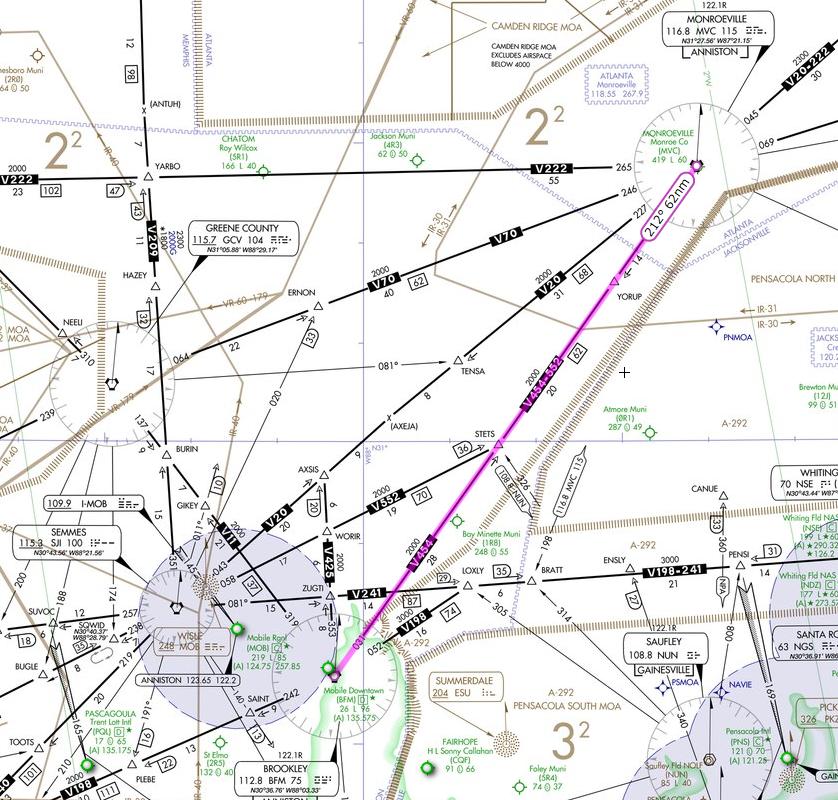
I3101 WORKSHEET. Planned Route: Takeoff: KMOB, RWY 33 Altitude: 5,000
|
|
|
- Edward Lucas
- 5 years ago
- Views:
Transcription
1 Planned Route: Takeoff: KMOB, RWY 33 Altitude: 5,000 I3101 WORKSHEET Airspeed 200 KIAS Destination: Monroe County via BFM1.STETS V454 MVC Approaches: KMVC VOR RWY 21 (SIM ONLY) (PT), VOR RWY 3 (SIM ONLY) (TD) Alternate: Mobile Downtown (KBFM) via MVC V454 BFM 6,000 Syllabus Notes May be conducted in the UTD Expected to fly all maneuvers without the use of FMS navigation o Left MFD will be set to Frequency page Special Syllabus Requirements None Discuss a. Clearance and departure procedures SID (BFM1.STETS) o Climb Via clearance o NAVAID Setup o Emergency return options b. VOR Procedure turn approach FTI Procedures (to the FAF) o Altitude restrictions PT altitude Segment altitudes MDA o Remain within distance restrictions o Flying the Barb o Type of intercept on inbound turn When more than 5 radials from inbound course during the initial turn When less than 5 radials from inbound course during the initial turn o BAC transition point BLT with MAYO mnemonic FTI Procedures for Final Approach Segment (FAF MAP) When the PT is not required c. VOR Teardrop approach FTI Procedures o Altitude restrictions 1
2 Segment altitudes MDA o Remain within distance restrictions o Outbound to inbound radial intercept o Type of intercept on inbound turn When more than 5 radials from inbound course during the initial turn When less than 5 radials from inbound course during the initial turn o BAC transition point d. 6 T s At the IAF At the FAF e. FAF-MAP timing adjustments Computations f. VDP Published verses non-published Associated altitude restriction when published Alignment with installed VASI/PAPI systems Computation VDP when not published VDP verses MAP requirements/considerations g. Missed approach MAP instructions o Published o Assigned climbout instructions MAP identification o Examples: Timing DME DME backed up with timing Station passage Priorities o Aviate o Navigate o Communicate Options following a missed approach o DRAFT mnemonic h. Traffic Advisories Practices at Airports Without Operating Control Towers i. Any emergency procedure 2
3 T-6B Radio Instruments I3100 Block STUDENT GRADE SHEET DATE INSTRUCTOR MEDIA: OFT VT- BRIEF TIME: NAME: EVENT: # MANEUVER MIF I3101 I3102 I3103 I3104 I GENERAL KNOWLEDGE / PROCEDURES 3+ X X X X X X 2 EMERGENCY PROCEDURES 3+ X X X X X X 3 HEADWORK / SITUATIONAL AWARENESS 3+ X X X X X X 4 BASIC AIRWORK 3+ X X X X X X 5 IN-FLIGHT CHECKS / FUEL MANAGEMENT 3+ X X X X X X 6 IN-FLIGHT PLANNING/AREA ORIENTATION 3 7 TASK MANAGEMENT 3+ X X X X X X 8 COMMUNICATION 3+ X X X X X X 9 MISSION PLANNING/BRIEFING/DEBRIEFING 3+ X X X X X X 10 GROUND OPERATIONS 4 11 TAKEOFF 4+ X X X X X X 12 DEPARTURE 3+ X X X X X X 44 RADIAL INTERCEPTS 3+ X X X 45 POINT-TO-POINT 3+ X 49 HOLDING 2+ X X X X 50 ENROUTE PROCEDURES 2+ X X X X X X 51 ENROUTE DESCENT 2+ X X X X X X 52 HIGH-ALTITUDE APPROACH 2 53 TEARDROP APPROACH 2+ X 54 ARCING APPROACH 2+ X 55 HILO APPROACH 2+ X 56 PROCEDURE TURN APPROACH 2+ X 57 RVFAC APPROACH 2+ X 58 GPS APPROACH 2 59 PAR APPROACH 2+ X 60 ASR APPROACH 2+ X 61 VOR FINAL 2+ X X X 62 ILS FINAL 2+ X X 63 LOC FINAL 2+ X X 64 GPS FINAL 2 65 BACKUP FLIGHT INSTRUMENT APPROACH 2 66 CIRCLING APPROACH 2 67 MISSED APPROACH 2+ X X X X X X 68 TRANSITION TO LANDING / LANDING 3 NOTES: I3105 AND I3106 shall be under simulated night conditions. I may be conducted in the UDT. During this phase of training, the student will be expected to fly all maneuvers without the use of FMS navigation. I3101 and I3102 shall only be scheduled as one event per day. DISCUSS ITEMS: I3101: Clearance and departure procedures, VOR procedure turn and teardrop approaches, 6T s, FAF-to-MAP timing adjustments, VDP, and missed approach. I3102: Holding, HILO approaches, oil system malfunctions, shuttle descent, and intersections. I3103: PAR, ASR, IMC emergencies, and propeller malfunctions. I3104: RVFAC, ILS/LOC procedures, and fuel system malfunctions. I3105: Arcing, night procedures, night lighting, night cockpit setup, and hydraulics system malfunctions. I3106: SID / STAR, obstacle departure procedure, Trouble T, and obtaining IFR clearance from uncontrolled airports. DEPART ARRIVE SIDE # SIM TIME JPPT B Rev 03/30/2017
4 (BFM1.STETS) BROOKLEY ONE DEPARTURE S ATIS CLNC DEL GND CON MOBILE TOWER (CTAF) MOBILE APP CON UNICOM TC-001 (CUBIC) SIMULATOR USE ONLY MONROEVILLE MVC Chan 115 N W L-22 MOBILE RGNL (MOB) MOBILE, ALABAMA YORUP STETS 3000 TAKEOFF OBSTACLE NOTES: Rwy 15: Tree 1758' from DER, 886' right of centerline 79' AGL/270' MSL. Tree 1987' from DER, 856' left of centerline, 73' AGL/277' MSL. Tree 2102' from DER, 861' right of centerline, 78' AGL/269' MSL. Tree 2131' from DER, left of centerline, 76' AGL/280' MSL BROOKLEY BFM Chan 75 BFM 3100 TOP ALTITUDE: 5000 N W L-22, H-6, H-8 SIMULATOR USE ONLY DEPARTURE ROUTE DESCRIPTION Note: Chart not to scale TAKE-OFF RWY 15: Turn left to heading 045, Intercept BFM R-031. Thence TAKE-OFF RWY 33: Climb runway heading 330. Arc CW North of BFM via the 15 DME arc, Intercept BFM R-031. Thence Maintain 5000 or ATC assigned altitude. Expect clearance to filed altitude 10 minutes after departure. BROOKLEY ONE DEPARTURE (BFM1.STETS) 16 JUN 17 MOBILE, ALABAMA MOBILE RGNL (MOB)
5 R AIM CHG 2 12/10/15 3/15/07 5/26/16 (c) Determine if obstacle avoidance can be maintained visually or if the ODP should be flown; and (d) Consider the effect of degraded climb performance and the actions to take in the event of an engine loss during the departure. Pilots should notify ATC as soon as possible of reduced climb capability in that circumstance. NOTE Guidance concerning contingency procedures that address an engine failure on takeoff after V 1 speed on a large or turbine powered transport category airplane may be found in AC , Airport Obstacle Analysis. 2. Pilots should not exceed a published speed restriction associated with a SID waypoint until passing that waypoint. 3. After an aircraft is established on an SID and subsequently vectored or cleared to deviate off of the SID or SID transition, pilots must consider the SID canceled, unless the controller adds expect to resume SID; pilots should then be prepared to rejoin the SID at a subsequent fix or procedure leg. If the SID contains published altitude restrictions, pilots should expect the controller to issue an altitude to maintain. ATC may also interrupt the vertical navigation of a SID and provide alternate altitude instructions while the aircraft remains established on the published lateral path. Aircraft may not be vectored off of an ODP or issued an altitude lower than a published altitude on an ODP until at or above the MVA/MIA, at which time the ODP is canceled. 4. Aircraft instructed to resume a procedure such as a DP or SID which contains speed and/or altitude restrictions, must be: or (a) Issued/reissued all applicable restrictions, (b) Advised to comply with restrictions or resume published speed. EXAMPLE Resume the Solar One departure, comply with restrictions. Proceed direct CIROS, resume the Solar One departure, comply with restrictions. 5. A clearance for a SID which contains published altitude restrictions may be issued using the phraseology climb via. Climb via is an abbreviated clearance that requires compliance with the procedure lateral path, associated speed and altitude restrictions along the cleared route or procedure. Clearance to climb via authorizes the pilot to: (a) When used in the IFR departure clearance, in a PDC, DCL or when cleared to a waypoint depicted on a SID, to join the procedure after departure or to resume the procedure. (b) When vertical navigation is interrupted and an altitude is assigned to maintain which is not contained on the published procedure, to climb from that previously-assigned altitude at pilot s discretion to the altitude depicted for the next waypoint. (c) Once established on the depicted departure, to navigate laterally and climb to meet all published or assigned altitude and speed restrictions. NOTE 1. When otherwise cleared along a route or procedure that contains published speed restrictions, the pilot must comply with those speed restrictions independent of a climb via clearance. 2. ATC anticipates pilots will begin adjusting speed the minimum distance necessary prior to a published speed restriction so as to cross the waypoint/fix at the published speed. Once at the published speed ATC expects pilots will maintain the published speed until additional adjustment is required to comply with further published or ATC assigned speed restrictions or as required to ensure compliance with 14 CFR Section If ATC interrupts lateral/vertical navigation while an aircraft is flying a SID, ATC must ensure obstacle clearance. When issuing a climb via clearance to join or resume a procedure ATC must ensure obstacle clearance until the aircraft is established on the lateral and vertical path of the SID. 4. ATC will assign an altitude to cross if no altitude is depicted at a waypoint/fix or when otherwise necessary/ required, for an aircraft on a direct route to a waypoint/fix where the SID will be joined or resumed. 5. SIDs will have a top altitude; the top altitude is the charted maintain altitude contained in the procedure description or assigned by ATC. REFERENCE FAAO , Paragraph 5-6-2, Methods PCG, Climb Via, Top Altitude EXAMPLE 1. Lateral route clearance: Cleared Loop Six departure Departure Procedures
6 Obtain local altimeter setting on CTAF, when not received, use Evergreen altimeter setting and increase all MDA 60 feet and S-21 Cats C/D visibility ½ mile and FATUN fix minimums increase S-21 Cats C/D visibility ½ mile. Helicopter visibility reduction below 1 SM not authorized. Rwy 21 Straight-in and Circling and Circling Rwy 03 NA MISSED APPROACH: Climb to 2000 on MVC R-212 to YORUP Int/MVC 14.0 DME. ATLANTA CENTER UNICOM (CTAF) SIMULATOR USE ONLY FATUN MVC 3 MISSED APCH FIX YORUP SIMULATOR USE ONLY 2000 YORUP MVC R-212


7 Obtain local altimeter setting on CTAF, when not received, use Evergreen altimeter setting and increase all MDAs 60 feet and S-3 Cats C/D visibility ¼ mile, and FONGU fix minimums increase S-3 Cats C/D visibility ¼ mile. Helicopter visibility reduction below 1 SM not authorized. Rwy 03 Straight-in and Circling and Circling Rwy 21 NA at night. MISSED APPROACH: Climb to 5000 on MVC R-045 to PICKS/MVC 30.0 DME MISSED APCH FIX SIMULATOR USE ONLY PICKS MVC 30.0 SIMULATOR USE ONLY SIMULATOR USE ONLY 5000 MVC R-045 PICKS 2000
8
9 CHAPTER EIGHT PRIMARY INSTRUMENT NAVIGATION T-6B 814. PROCEDURE TURN APPROACH General Reverse the aircraft heading within assigned airspace in order to align it with the final approach course. Description The Procedure Turn Approach is an instrument maneuver used to reverse direction and establish the aircraft inbound on the intermediate or final approach course while insuring the Remain Within distance is observed. Procedure Turns are depicted by a barb symbol on the approach plate. The Barb indicates which side of the outbound course to complete the turn (Figure 8-8). Headings are provided to reverse course using a 45/180 degrees type maneuver. However, the point at which the turn may be commenced and the type and rate of turn, are left to the discretion of the pilot, as long as the Procedure Turn is executed on the proper side of the outbound course and the Remain Within distance (normally 10 NM) is not exceeded. Options for this type of maneuver include the 45/180 degrees course reversal, the racetrack pattern, or the 80/260 degree course reversal. During Primary training, only the 45/180 degrees course reversal will be practiced. Do NOT execute a Procedure Turn when: 1. ATC clears you for a Straight-in approach. 2. Flying the approach via NoPT routing. 3. Established in a holding pattern aligned with the procedure turn course and subsequently cleared for the approach. 4. ATC Radar vectors you to final. 5. Cleared for a Timed approach. SNERT is a useful mnemonic to aid in recall of these restrictions. Procedure The following procedures assume clearance for the DAYTONA BEACH INTERNATIONAL VOR RWY 16 approach (Figure 8-8) has been received and you are proceeding to the IAF. 1. Approximately 5 NM prior to the IAF, slow to 150 KIAS. At the IAF, indicated by station passage, execute the 6 Ts (Over-the-Station Intercept): a. TIME - Not required TERMINAL PROCEDURES
10 PRIMARY INSTRUMENT NAVIGATION T-6B CHAPTER EIGHT b. TURN - in the shortest direction to parallel the outbound course (336º). If the outbound course is more than 90 from the course used inbound to the IAF, turn to an intercept heading not to exceed 45. c. TIME - Start timing for one (1) minute outbound when wings level or abeam the station, whichever occurs last. NOTE Comply with the remain within distance if stated on the approach plate. d. TRANSITION - If a descent is necessary at the IAF, set approximately 15% torque, lower the nose, and descend at 150 KIAS. NOTE Comply with any additional altitude restrictions imposed by ATC. e. TWIST/ Intercept i. Set CDI to the outbound course (336º). ii. Use Over-the-Station Intercept procedures to establish the aircraft on course outbound. The objective is to be established on the outbound radial by the end of one minute. f. TALK - Give an appropriate voice report if required. 2. Level-off at Procedure Turn altitude (1600 ). a. Approximately 100 prior to the Procedure Turn altitude, add power smoothly towards 33% torque as you raise the nose to level flight attitude and re-trim. b. Maintain Procedure Turn altitude until you are established on the inbound course. NOTE The aircraft is not considered established on course until the head of the bearing pointer is within five radials of the inbound course. With the CDI set correctly, the course deviation bar will be between the one dot and centered position. 3. At the end of outbound timing, execute the 45/180 degrees course reversal by turning 45 to the heading depicted on the barb symbol (291º). Start the clock as you roll wings level and maintain this heading for one (1) minute. Twist in the inbound course (156º) in the CDI. TERMINAL PROCEDURES 8-15
11 CHAPTER EIGHT PRIMARY INSTRUMENT NAVIGATION T-6B 4. At the end of one (1) minute timing, execute a 180º turn in a direction opposite the first turn (i.e., turn away from the station). Approaching the barb heading (111 ), note the head of the bearing pointer. a. If the head of the bearing pointer is not within 5 of the inbound course, stop the turn on the heading depicted on the barb (111 ). b. If the head of the needle is within 5 of the inbound course, continue the turn and roll out with a double-the-angle intercept. If you overshoot the inbound course, turn to establish an appropriate intercept. 5. As you intercept the inbound course, turn and track inbound. 6. Once established on the inbound course, and within 5 NM of the FAF (when DME is available), configure to BAC. Maintain altitude until reaching 120 KIAS then commence any descent required (Slow Down, Then Go Down). In this case maintain 1600 until the FAF. 7. Comply with the remainder of the Low Altitude Instrument Approach Procedures TERMINAL PROCEDURES
 TERMINAL PROCEDURES")
12 PRIMARY INSTRUMENT NAVIGATION T-6B CHAPTER EIGHT Figure 8-8 VOR RWY 16 (KDAB) TERMINAL PROCEDURES 8-17
13 CHAPTER EIGHT PRIMARY INSTRUMENT NAVIGATION T-6B 814. PROCEDURE TURN APPROACH General Reverse the aircraft heading within assigned airspace in order to align it with the final approach course. Description The Procedure Turn Approach is an instrument maneuver used to reverse direction and establish the aircraft inbound on the intermediate or final approach course while insuring the Remain Within distance is observed. Procedure Turns are depicted by a barb symbol on the approach plate. The Barb indicates which side of the outbound course to complete the turn (Figure 8-8). Headings are provided to reverse course using a 45/180 degrees type maneuver. However, the point at which the turn may be commenced and the type and rate of turn, are left to the discretion of the pilot, as long as the Procedure Turn is executed on the proper side of the outbound course and the Remain Within distance (normally 10 NM) is not exceeded. Options for this type of maneuver include the 45/180 degrees course reversal, the racetrack pattern, or the 80/260 degree course reversal. During Primary training, only the 45/180 degrees course reversal will be practiced. Do NOT execute a Procedure Turn when: 1. ATC clears you for a Straight-in approach. 2. Flying the approach via NoPT routing. 3. Established in a holding pattern aligned with the procedure turn course and subsequently cleared for the approach. 4. ATC Radar vectors you to final. 5. Cleared for a Timed approach. SNERT is a useful mnemonic to aid in recall of these restrictions. Procedure The following procedures assume clearance for the DAYTONA BEACH INTERNATIONAL VOR RWY 16 approach (Figure 8-8) has been received and you are proceeding to the IAF. 1. Approximately 5 NM prior to the IAF, slow to 150 KIAS. At the IAF, indicated by station passage, execute the 6 Ts (Over-the-Station Intercept): a. TIME - Not required TERMINAL PROCEDURES
14 CHAPTER NINE FINAL APPROACH PROCEDURES 900. INTRODUCTION The previous chapter covered how to safely navigate to the final approach fix. This chapter will cover the segment between the FAF to the MAP. This segment of the approach is the most demanding, as the aircraft is slow, low, and configured NON-PRECISION APPROACH General Fly the final segment of the instrument approach on speed, on course and arrive at the published MDA prior to the MAP to set the aircraft up for landing. Description The final segment for Non-Precision approaches may include the following variations. 1. Approaches requiring a small course change at the final approach fix. 2. Approaches without a FAF. 3. Visual Descent Points (VDPs). 4. Approaches with or without DME. 5. MAPs identified by timing, DME, DME backed up with timing, or station passage. Procedure For the following example, assume the aircraft is at the FAF for the VOR or GPS RWY 16 (KDAB) (Figure 9-1), configured in BAC. 1. Perform 6 Ts: a. TIME - Start timing if given (backup to identify the MAP if DME fails). b. TURN - Turn in the shortest direction to parallel the final approach course (156º). c. TIME - Not required. d. TRANSITION - Set approximately 15% torque, trim for 120 KIAS descent to next segment altitude or MDA, as required (700 MDA). FINAL APPROACH PROCEDURES 9-1
15 CHAPTER NINE PRIMARY INSTRUMENT NAVIGATION T-6B NOTE Adjust pitch to maintain airspeed; use power as required to maintain a stabilized rate of descent not to exceed 1000 fpm. e. TWIST - If not already done, twist the final approach course (FAC) into the CDI (156º) and set intercept as required. f. TALK - Give the appropriate voice report if required. 2. Approximately 100 prior to MDA, slowly add power to arrest the rate of descent. 3. Level off at the MDA (700 ) at or before the published or derived VDP in order to have a normal descent angle to land, and maintain 120 KIAS (approximately 42% torque). Proceed to the MAP (7.4 DME). NOTE Do not descend below the MDA, even if the field is in sight, until reaching the VDP. In this example, a VDP of 5.2 DME is calculated using procedures outlined in this chapter and Appendix B. NOTE Avoid rapid descent requirements on final by crossing the FAF at the published altitude. Note that you can descend from the FAF once on the appropriate heading outbound from the station or the appropriate radial inbound. Do not wait to descend until the needle settles out from the cone of confusion. 4. Once the field is in sight and a safe landing can be made, maneuver to land. 5. At the MAP, if the field is not in sight or a safe landing cannot be made, execute a Missed Approach. Visual Descent Point Depending on the location of the MAP, the descent from the MDA often will have to be initiated prior to reaching the MAP in order to execute a normal (approximately 3 ) descent to landing. This point is called the Visual Descent Point (VDP). The VDP will often be published on the approach chart; if not depicted, it may be computed. 9-2 FINAL APPROACH PROCEDURES
16 PRIMARY INSTRUMENT NAVIGATION T-6B CHAPTER NINE WARNING While the FAA is attempting to place more VDPs on approaches, it should be noted that if there is a penetration of the obstruction clearance surface on final, they will not publish a VDP. Therefore, if there is no VDP published, it may be for a reason. If choosing to calculate a VDP, it may be used, but be vigilant looking for obstacles from the VDP to landing. The first step to computing a VDP is to divide the HAT by your desired descent gradient. Most pilots desire approximately a 3 (300 ft/nm) glidepath for landing utilizing the following formula: HAT/Gradient (normally 300) = VDP in NM from end of runway This distance can then be added/subtracted to/from the DME at the end of the runway to get a DME for your VDP. Example: HAT = 665 FT, MDA = 700 FT MSL, DME at the end of the runway = 7.4 DME VDP = HAT/Gradient = 665/300 = 2.2 NM from end of runway VDP DME = DME at end of runway - VDP distance = 7.4 DME DME = 5.2 DME Common Errors 1. Excessive corrections over or near the VOR. 2. Failure to back up DME with timing where appropriate. 3. Descending below MDA. 4. Late recognizing the MAP. FINAL APPROACH PROCEDURES 9-3
17 CHAPTER NINE PRIMARY INSTRUMENT NAVIGATION T-6B Figure 9-1 VOR or GPS RWY 16 (KDAB) 9-4 FINAL APPROACH PROCEDURES
18 CHAPTER EIGHT PRIMARY INSTRUMENT NAVIGATION T-6B 815. TEARDROP APPROACH General Reverse the aircraft heading in order to align it with the final approach course. Description A Teardrop approach makes use of an outbound to inbound radial intercept maneuver to reverse course and establish the aircraft inbound on the intermediate or final approach course while insuring the Remain Within distance is observed. A Non-Depicted Teardrop approach is an authorized variant to the Procedure Turn, and is flown by intercepting an outbound radial offset 20 to the protected barb side of the Procedure Turn Final Approach Course. Procedure The following procedures assume clearance for the ROBINS AFB VOR RWY 15 approach (Figure 8-9) has been received and you are proceeding to the IAF. 1. Approximately 5 NM prior to the IAF, slow to 150 KIAS. At the IAF, indicated by station passage, execute the 6 Ts (Over-the-Station Intercept): a. TIME - Not required. b. TURN - Turn in the shortest direction to parallel the outbound course (295º). If the outbound course is more than 90 from the course used inbound to the IAF, turn to an intercept heading not to exceed 45. c. TIME - Start timing for two (2) minutes outbound when wings level or abeam the station, whichever occurs last. NOTE In strong winds or at indicated speeds greater than 150 KIAS, you may have to adjust outbound timing to comply with any Remain Within distance associated with the approach. Normally, (2) two minutes timing outbound will be sufficient. d. TRANSITION - If a descent is necessary at the IAF, set approximately 15% torque, and descend at 150 KIAS. NOTE Comply with any additional altitude restrictions imposed by ATC TERMINAL PROCEDURES
19 PRIMARY INSTRUMENT NAVIGATION T-6B CHAPTER EIGHT e. TWIST /Intercept i. Set the outbound course (295º) into the CDI. ii. Use Over-the-Station Intercept Procedures to establish the aircraft on course outbound. The objective is to be established on the outbound radial by the end of one minute. f. TALK - Give an appropriate voice report if required. 2. Level-off at Procedure Turn altitude (2300 ). a. Approximately 100 prior to the Procedure Turn altitude, add power and raise the nose to maintain 150 KIAS in level flight. Continue to re-trim. b. Maintain Procedure Turn altitude until you are established on the inbound course. NOTE The aircraft is not considered established on course until the head of the bearing pointer is within five radials of the inbound course. With the CDI set correctly, the course deviation bar will be between the one dot and centered position. 3. After 1 ½ minutes of outbound timing, twist inbound course into the CDI (134º). 4. At two (2) minutes of outbound timing, execute a turn in the direction depicted (in this case, turn right). During the turn inbound note the position of the bearing pointer: a. If the head of the bearing pointer is not within 5º of the inbound course, stop the turn with a 45º intercept. b. If the head of the bearing pointer is within 5º of the inbound course, you should roll out with a double the angle intercept. If you overshoot the inbound course, turn to establish an appropriate intercept. 5. Once established on the inbound course, and within 5 NM of the FAF (when DME is available), configure to BAC. Maintain altitude until reaching 120 KIAS then commence any descent required (in this case descend to 1500 MSL, Slow Down, Then Go Down). 6. Comply with the remainder of the Low Altitude Instrument Approach Procedures. NOTE To facilitate training, if local VOR approaches do not have a Teardrop procedure available, a procedure turn approach may be TERMINAL PROCEDURES 8-19
20 CHAPTER EIGHT PRIMARY INSTRUMENT NAVIGATION T-6B used to substitute by intercepting an outbound radial offset 20º to the barb side of a depicted procedure turn Final approach course and continue with FTI procedures for a Teardrop procedure turn. Figure 8-9 VOR RWY 15 (KWRB) 8-20 TERMINAL PROCEDURES
21 APPROACH Missed approach timing adjustments when ground speed is less than 120 KTS can be quickly computed using the following method. Note the distance from the FAF to MAP (5.6 nm). Disregarding the decimal point, this just happens to be the number of seconds between the 90 an 120 KT times. 3:44 2:48 = 56 seconds. Dividing that by 3 will give you the number of seconds to adjust for every 10 KTS of groundspeed change. 56 / 3 = 18.6 or about -20 seconds for every 10 KTS of speed change -10 seconds for every 5 KTS of speed change NOTE This method is just a quick way to compute adjustments between 90 an 120 KTS. It is not as accurate for other speeds.
22 CHAPTER NINE PRIMARY INSTRUMENT NAVIGATION T-6B NOTE Adjust pitch to maintain airspeed; use power as required to maintain a stabilized rate of descent not to exceed 1000 fpm. e. TWIST - If not already done, twist the final approach course (FAC) into the CDI (156º) and set intercept as required. f. TALK - Give the appropriate voice report if required. 2. Approximately 100 prior to MDA, slowly add power to arrest the rate of descent. 3. Level off at the MDA (700 ) at or before the published or derived VDP in order to have a normal descent angle to land, and maintain 120 KIAS (approximately 42% torque). Proceed to the MAP (7.4 DME). NOTE Do not descend below the MDA, even if the field is in sight, until reaching the VDP. In this example, a VDP of 5.2 DME is calculated using procedures outlined in this chapter and Appendix B. NOTE Avoid rapid descent requirements on final by crossing the FAF at the published altitude. Note that you can descend from the FAF once on the appropriate heading outbound from the station or the appropriate radial inbound. Do not wait to descend until the needle settles out from the cone of confusion. 4. Once the field is in sight and a safe landing can be made, maneuver to land. 5. At the MAP, if the field is not in sight or a safe landing cannot be made, execute a Missed Approach. Visual Descent Point Depending on the location of the MAP, the descent from the MDA often will have to be initiated prior to reaching the MAP in order to execute a normal (approximately 3 ) descent to landing. This point is called the Visual Descent Point (VDP). The VDP will often be published on the approach chart; if not depicted, it may be computed. 9-2 FINAL APPROACH PROCEDURES
23 PRIMARY INSTRUMENT NAVIGATION T-6B CHAPTER NINE WARNING While the FAA is attempting to place more VDPs on approaches, it should be noted that if there is a penetration of the obstruction clearance surface on final, they will not publish a VDP. Therefore, if there is no VDP published, it may be for a reason. If choosing to calculate a VDP, it may be used, but be vigilant looking for obstacles from the VDP to landing. The first step to computing a VDP is to divide the HAT by your desired descent gradient. Most pilots desire approximately a 3 (300 ft/nm) glidepath for landing utilizing the following formula: HAT/Gradient (normally 300) = VDP in NM from end of runway This distance can then be added/subtracted to/from the DME at the end of the runway to get a DME for your VDP. Example: HAT = 665 FT, MDA = 700 FT MSL, DME at the end of the runway = 7.4 DME VDP = HAT/Gradient = 665/300 = 2.2 NM from end of runway VDP DME = DME at end of runway - VDP distance = 7.4 DME DME = 5.2 DME Common Errors 1. Excessive corrections over or near the VOR. 2. Failure to back up DME with timing where appropriate. 3. Descending below MDA. 4. Late recognizing the MAP. FINAL APPROACH PROCEDURES 9-3
24 APPENDIX B PRIMARY INSTRUMENT NAVIGATION T-6B Calculate VDP HAT (in 100s of feet) Distance from the runway = Gradient GUS wears a HAT Calculate Gradient 100s of feet Distance in nm = Descent Gradient in Degrees Calculate Required Rate of Descent (VSI) NM Min x 100 ft x Gradient = Required VSI B-2 60-TO-1 RULE AND OTHER FORMULAS
25 CHAPTER ELEVEN T-6B PRIMARY INSTRUMENT NAVIGATION Adherence to these procedures will assure that an aircraft will remain within the circling and Missed Approach obstruction clearance areas. Figure 11-3 Missed Approach from a Circling Maneuver NOTE At locations where ATC Radar Service is provided, ATC may provide modified climbout instructions in lieu of the published Missed Approach procedure MISSED APPROACH Description. A Missed Approach is a procedure used to discontinue an instrument approach if the runway environment is not in sight, or the aircraft is not in a position to make a safe landing. The primary concern, if unable to land, is to climb to a safe altitude. Therefore, establishing and maintaining a positive rate of climb should be your first priority if a Missed Approach is commenced. Your second priority should be to turn the aircraft (if required) to intercept the Missed Approach course or to the designated heading. The Missed Approach instructions are found in the profile view of the approach plate. The student shall review the Missed Approach prior to the FAF, or once established on final, if no FAF is depicted TRANSITION TO LANDING AND MISSED APPROACH
26 T-6B PRIMARY INSTRUMENT NAVIGATION CHAPTER ELEVEN NOTE When flying practice approaches, ATC frequently assigns climbout instructions that differ from the published Missed Approach procedures. You are expected to fly the assigned climbout instructions vice Missed Approach procedures when executing a Missed Approach. Missed Approach Prior to the FAF If executing an instrument approach and full scale deflection of the CDI occurs PRIOR to the FAF, the pilot should make every attempt to return back onto course. If unable to reestablish the aircraft on course, do not descend below the FAF altitude, inform ATC, and follow ATC instructions. Missed Approach Between the FAF and MAP If executing an instrument approach and full scale deflection of the CDI occurs at any time between the FAF and the MAP, begin an IMMEDIATE climb to the depicted Missed Approach altitude (or altitude ATC has assigned in the event of a Missed Approach), fly to the MAP and execute the Missed Approach procedure. Advise ATC at the earliest opportunity. Set an intercept heading to establish the aircraft back on the final approach course. WARNING Obstacle clearance is not ensured when the aircraft is off the published portions of an approach. With full scale deflection of the CDI in areas of high terrain or obstacles, a climb to the Minimum Safe Altitude (MSA) may be required. Procedure. At the MAP, if sufficient visual cues are not available, or a safe landing cannot be made, execute a Missed Approach as follows: 1. Increase PCL to MAX. 2. Raise the nose to a positive climbing attitude (10-15º nose up). 3. Check for a positive rate of climb (check the altimeter and VSI). 4. Raise the landing gear and flaps. 5. Start a SRT toward the Missed Approach course or heading. Stay on the attitude indicator and maintain the climbing attitude. TRANSITION TO LANDING AND MISSED APPROACH 11-5
27 CHAPTER ELEVEN T-6B PRIMARY INSTRUMENT NAVIGATION 6. Establish an intercept to the Missed Approach course or continue the turn to the designated heading as required. 7. Make the Missed Approach report to Tower. 8. Level-off at Missed Approach altitude. 9. If directed to contact approach control, inform them of your Missed Approach and state your intentions. Options include: a. Request the same approach. If you flew a bad approach due to your own poor basic airwork, you might request to fly the same approach again. b. Request a different approach with lower minimums, if available. c. Proceed to your alternate. If weather and/or fuel considerations dictate that you proceed to your alternate, coordinate with ATC to obtain clearance. 10. Update the weather as appropriate. Common Errors. 1. Poor Instrument Scan/Poor Airwork. 2. Slow to establish a climb. 3. Not distinguishing the differences between a depicted heading and a radial outbound. 4. Not trimming as the aircraft accelerates TRANSITION TO LANDING AND MISSED APPROACH

28 CLEARANCE TO AN ALTERNATE -A helpful format for requesting clearance to an alternate from ATC is the DRAFT report. TEXAN 123, request clearance to Pensacola Gulf Coast Regional, via SAINT V198 PENSI, at 3000, Fuel 1+10, Time TEXAN 123, you are cleared to the Pensacola Regional Airport, as requested, climb and maintain Destination Airport -Route of flight -Altitude -Fuel onboard (hr+min) -Time enroute (hr+min) Looking at our chart, PENSI is an IAF for the ILS to our alternate Pensacola RGNL. SAINT (our holding fix) is on the V198 airway that goes all the way to PENSI feet is the MEA for V198 and complies with semi-circular rules going east. Our total fuel onboard divided by our cruise fuel flow in PPH will give us fuel onboard in hours and minutes The distance from SAINT to PENSI is 52 nm. TEXAN 123, cleared to Pensacola Gulf Coast Regional, as requested, leaving 2000 for Note this is an example of an abbreviated clearance.
29 AIM 4/3/ Operation Take-off and Operation Raincheck Operation Take-off is a program that educates pilots in how best to utilize the FSS modernization efforts and services available in Flight Service Stations (FSS), as stated in FAA Order , Pilot Education Program Operation Takeoff. Operation Raincheck is a program designed to familiarize pilots with the ATC system, its functions, responsibilities and benefits Approach Control Service for VFR Arriving Aircraft a. Numerous approach control facilities have established programs for arriving VFR aircraft to contact approach control for landing information. This information includes: wind, runway, and altimeter setting at the airport of intended landing. This information may be omitted if contained in the Automatic Terminal Information Service (ATIS) broadcast and the pilot states the appropriate ATIS code. NOTE Pilot use of have numbers does not indicate receipt of the ATIS broadcast. In addition, the controller will provide traffic advisories on a workload permitting basis. b. Such information will be furnished upon initial contact with concerned approach control facility. The pilot will be requested to change to the tower frequency at a predetermined time or point, to receive further landing information. c. Where available, use of this procedure will not hinder the operation of VFR flights by requiring excessive spacing between aircraft or devious routing. d. Compliance with this procedure is not mandatory but pilot participation is encouraged. REFERENCE AIM, Terminal Radar Services for VFR Aircraft, Paragraph NOTE Approach control services for VFR aircraft are normally dependent on ATC radar. These services are not available during periods of a radar outage. Approach control services for VFR aircraft are limited when CENRAP is in use Traffic Advisory Practices at Airports Without Operating Control Towers (See TBL ) a. Airport Operations Without Operating Control Tower 1. There is no substitute for alertness while in the vicinity of an airport. It is essential that pilots be alert and look for other traffic and exchange traffic information when approaching or departing an airport without an operating control tower. This is of particular importance since other aircraft may not have communication capability or, in some cases, pilots may not communicate their presence or intentions when operating into or out of such airports. To achieve the greatest degree of safety, it is essential that all radio-equipped aircraft transmit/receive on a common frequency identified for the purpose of airport advisories. 2. An airport may have a full or part-time tower or FSS located on the airport, a full or part-time UNICOM station or no aeronautical station at all. There are three ways for pilots to communicate their intention and obtain airport/traffic information when operating at an airport that does not have an operating tower: by communicating with an FSS, a UNICOM operator, or by making a self-announce broadcast. 3. Many airports are now providing completely automated weather, radio check capability and airport advisory information on an automated UNICOM system. These systems offer a variety of features, typically selectable by microphone clicks, on the UNICOM frequency. Availability of the automated UNICOM will be published in the Airport/Facility Directory and approach charts. b. Communicating on a Common Frequency 1. The key to communicating at an airport without an operating control tower is selection of the correct common frequency. The acronym CTAF which stands for Common Traffic Advisory Frequency, is synonymous with this program. A CTAF is a frequency designated for the purpose of carrying out airport advisory practices while operating to or from an airport without an operating control tower. The CTAF may be a UNICOM, MULTICOM, FSS, or tower frequency and is identified in appropriate aeronautical publications Services Available to Pilots
30 4/3/14 AIM TBL Summary of Recommended Communication Procedures Communication/Broadcast Procedures Facility at Airport Frequency Use Outbound Inbound 1. UNICOM (No Tower or FSS) 2. No Tower, FSS, or UNICOM 3. No Tower in operation, FSS open Communicate with UNICOM station on published CTAF frequency (122.7; 122.8; ; ; or 123.0). If unable to contact UNICOM station, use self-announce procedures on CTAF. Self-announce on MULTICOM frequency Communicate with FSS on CTAF frequency. Before taxiing and before taxiing on the runway for departure. Before taxiing and before taxiing on the runway for departure. Before taxiing and before taxiing on the runway for departure. 4. FSS Closed (No Tower) Self-announce on CTAF. Before taxiing and before taxiing on the runway for departure. 5. Tower or FSS not in operation Self-announce on CTAF. Before taxiing and before taxiing on the runway for departure. 10 miles out. Entering downwind, base, and final. Leaving the runway. 10 miles out. Entering downwind, base, and final. Leaving the runway. 10 miles out. Entering downwind, base, and final. Leaving the runway. 10 miles out. Entering downwind, base, and final. Leaving the runway. 10 miles out. Entering downwind, base, and final. Leaving the runway. Practice Instrument Approach Departing final approach fix (name) or on final approach segment inbound. Approach completed/terminated. 2. The CTAF frequency for a particular airport is contained in the A/FD, Alaska Supplement, Alaska Terminal Publication, Instrument Approach Procedure Charts, and Instrument Departure Procedure (DP) Charts. Also, the CTAF frequency can be obtained by contacting any FSS. Use of the appropriate CTAF, combined with a visual alertness and application of the following recommended good operating practices, will enhance safety of flight into and out of all uncontrolled airports. c. Recommended Traffic Advisory Practices 1. Pilots of inbound traffic should monitor and communicate as appropriate on the designated CTAF from 10 miles to landing. Pilots of departing aircraft should monitor/communicate on the appropriate frequency from start-up, during taxi, and until 10 miles from the airport unless the CFRs or local procedures require otherwise. 2. Pilots of aircraft conducting other than arriving or departing operations at altitudes normally used by arriving and departing aircraft should monitor/communicate on the appropriate frequency while within 10 miles of the airport unless required to do otherwise by the CFRs or local procedures. Such operations include parachute jumping/dropping, en route, practicing maneuvers, etc. REFERENCE AIM, Parachute Jump Aircraft Operations, Paragraph d. Airport Advisory/Information Services Provided by a FSS 1. There are three advisory type services provided at selected airports. (a) Local Airport Advisory (LAA) is provided at airports that have a FSS physically located on the airport, which does not have a control tower or where the tower is operated on a part time basis. The CTAF for LAA airports is disseminated in the appropriate aeronautical publications. Services Available to Pilots 4 1 3
31 AIM 4/3/14 (b) Remote Airport Advisory (RAA) is provided at selected very busy GA airports, which do not have an operating control tower. The CTAF for RAA airports is disseminated in the appropriate aeronautical publications. (c) Remote Airport Information Service (RAIS) is provided in support of special events at nontowered airports by request from the airport authority. 2. In communicating with a CTAF FSS, check the airport s automated weather and establish two way communications before transmitting outbound/inbound intentions or information. An inbound aircraft should initiate contact approximately 10 miles from the airport, reporting aircraft identification and type, altitude, location relative to the airport, intentions (landing or over flight), possession of the automated weather, and request airport advisory or airport information service. A departing aircraft should initiate contact before taxiing, reporting aircraft identification and type, VFR or IFR, location on the airport, intentions, direction of take off, possession of the automated weather, and request airport advisory or information service. Also, report intentions before taxiing onto the active runway for departure. If you must change frequencies for other service after initial report to FSS, return to FSS frequency for traffic update. (a) Inbound EXAMPLE Vero Beach radio, Centurion Six Niner Delta Delta is ten miles south, two thousand, landing Vero Beach. I have the automated weather, request airport advisory. (b) Outbound EXAMPLE Vero Beach radio, Centurion Six Niner Delta Delta, ready to taxi to runway 22, VFR, departing to the southwest. I have the automated weather, request airport advisory. 3. Airport advisory service includes wind direction and velocity, favored or designated runway, altimeter setting, known airborne and ground traffic, NOTAMs, airport taxi routes, airport traffic pattern information, and instrument approach procedures. These elements are varied so as to best serve the current traffic situation. Some airport managers have specified that under certain wind or other conditions designated runways be used. Pilots should advise the FSS of the runway they intend to use. CAUTION All aircraft in the vicinity of an airport may not be in communication with the FSS. e. Information Provided by Aeronautical Advisory Stations (UNICOM) 1. UNICOM is a nongovernment air/ground radio communication station which may provide airport information at public use airports where there is no tower or FSS. 2. On pilot request, UNICOM stations may provide pilots with weather information, wind direction, the recommended runway, or other necessary information. If the UNICOM frequency is designated as the CTAF, it will be identified in appropriate aeronautical publications. f. Unavailability of Information from FSS or UNICOM Should LAA by an FSS or Aeronautical Advisory Station UNICOM be unavailable, wind and weather information may be obtainable from nearby controlled airports via Automatic Terminal Information Service (ATIS) or Automated Weather Observing System (AWOS) frequency. g. Self-Announce Position and/or Intentions 1. General. Self-announce is a procedure whereby pilots broadcast their position or intended flight activity or ground operation on the designated CTAF. This procedure is used primarily at airports which do not have an FSS on the airport. The self-announce procedure should also be used if a pilot is unable to communicate with the FSS on the designated CTAF. Pilots stating, Traffic in the area, please advise is not a recognized Self Announce Position and/or Intention phrase and should not be used under any condition. 2. If an airport has a tower and it is temporarily closed, or operated on a part-time basis and there is no FSS on the airport or the FSS is closed, use the CTAF to self-announce your position or intentions. 3. Where there is no tower, FSS, or UNICOM station on the airport, use MULTICOM frequency for self-announce procedures. Such airports will be identified in appropriate aeronautical information publications. 4. Practice Approaches. Pilots conducting practice instrument approaches should be particularly alert for other aircraft that may be departing in the Services Available to Pilots
32 4/3/14 AIM opposite direction. When conducting any practice approach, regardless of its direction relative to other airport operations, pilots should make announcements on the CTAF as follows: (a) Departing the final approach fix, inbound (nonprecision approach) or departing the outer marker or fix used in lieu of the outer marker, inbound (precision approach); (b) Established on the final approach segment or immediately upon being released by ATC; (c) Upon completion or termination of the approach; and (d) Upon executing the missed approach procedure. 5. Departing aircraft should always be alert for arrival aircraft coming from the opposite direction. 6. Recommended self-announce phraseologies: It should be noted that aircraft operating to or from another nearby airport may be making self-announce broadcasts on the same UNICOM or MULTICOM frequency. To help identify one airport from another, the airport name should be spoken at the beginning and end of each self-announce transmission. (a) Inbound EXAMPLE Strawn traffic, Apache Two Two Five Zulu, (position), (altitude), (descending) or entering downwind/base/final (as appropriate) runway one seven full stop, touch and go, Strawn. Strawn traffic Apache Two Two Five Zulu clear of runway one seven Strawn. (b) Outbound EXAMPLE Strawn traffic, Queen Air Seven One Five Five Bravo (location on airport) taxiing to runway two six Strawn. Strawn traffic, Queen Air Seven One Five Five Bravo departing runway two six. Departing the pattern to the (direction), climbing to (altitude) Strawn. (c) Practice Instrument Approach EXAMPLE Strawn traffic, Cessna Two One Four Three Quebec (position from airport) inbound descending through (altitude) practice (name of approach) approach runway three five Strawn. Strawn traffic, Cessna Two One Four Three Quebec practice (type) approach completed or terminated runway three five Strawn. h. UNICOM Communications Procedures 1. In communicating with a UNICOM station, the following practices will help reduce frequency congestion, facilitate a better understanding of pilot intentions, help identify the location of aircraft in the traffic pattern, and enhance safety of flight: (a) Select the correct UNICOM frequency. (b) State the identification of the UNICOM station you are calling in each transmission. (c) Speak slowly and distinctly. (d) Report approximately 10 miles from the airport, reporting altitude, and state your aircraft type, aircraft identification, location relative to the airport, state whether landing or overflight, and request wind information and runway in use. (e) Report on downwind, base, and final approach. (f) Report leaving the runway. 2. Recommended UNICOM phraseologies: (a) Inbound PHRASEOLOGY FREDERICK UNICOM CESSNA EIGHT ZERO ONE TANGO FOXTROT 10 MILES SOUTHEAST DESCENDING THROUGH (altitude) LANDING FREDERICK, REQUEST WIND AND RUNWAY INFORMATION FREDERICK. FREDERICK TRAFFIC CESSNA EIGHT ZERO ONE TANGO FOXTROT ENTERING DOWNWIND/BASE/ FINAL (as appropriate) FOR RUNWAY ONE NINER (full stop/touch and go)frederick. FREDERICK TRAFFIC CESSNA EIGHT ZERO ONE TANGO FOXTROT CLEAR OF RUNWAY ONE NINER FREDERICK. (b) Outbound PHRASEOLOGY FREDERICK UNICOM CESSNA EIGHT ZERO ONE TANGO FOXTROT (location on airport) TAXIING TO RUNWAY ONE NINER, REQUEST WIND AND TRAFFIC INFORMATION FREDERICK. FREDERICK TRAFFIC CESSNA EIGHT ZERO ONE TANGO FOXTROT DEPARTING RUNWAY ONE NINER. REMAINING IN THE PATTERN OR DEPARTING THE PATTERN TO THE (direction) (as appropriate) FREDERICK. Services Available to Pilots 4 1 5
33 AIM 4/3/ IFR Approaches/Ground Vehicle Operations a. IFR Approaches. When operating in accordance with an IFR clearance and ATC approves a change to the advisory frequency, make an expeditious change to the CTAF and employ the recommended traffic advisory procedures. b. Ground Vehicle Operation. Airport ground vehicles equipped with radios should monitor the CTAF frequency when operating on the airport movement area and remain clear of runways/taxiways being used by aircraft. Radio transmissions from ground vehicles should be confined to safety-related matters. c. Radio Control of Airport Lighting Systems. Whenever possible, the CTAF will be used to control airport lighting systems at airports without operating control towers. This eliminates the need for pilots to change frequencies to turn the lights on and allows a continuous listening watch on a single frequency. The CTAF is published on the instrument approach chart and in other appropriate aeronautical information publications. For further details concerning radio controlled lights, see AC 150/ , Air to Ground Radio Control of Airport Lighting Systems Designated UNICOM/MULTICOM Frequencies Frequency use a. The following listing depicts UNICOM and MULTICOM frequency uses as designated by the Federal Communications Commission (FCC). (See TBL ) TBL Unicom/Multicom Frequency Usage Use Frequency Airports without an operating control tower. (MULTICOM FREQUENCY) Activities of a temporary, seasonal, emergency nature or search and rescue, as well as, airports with no tower, FSS, or UNICOM. (MULTICOM FREQUENCY) Forestry management and fire suppression, fish and game management and protection, and environmental monitoring and protection. Airports with a control tower or FSS on airport NOTE 1. In some areas of the country, frequency interference may be encountered from nearby airports using the same UNICOM frequency. Where there is a problem, UNICOM operators are encouraged to develop a least interference frequency assignment plan for airports concerned using the frequencies designated for airports without operating control towers. UNICOM licensees are encouraged to apply for UNICOM 25 khz spaced channel frequencies. Due to the extremely limited number of frequencies with 50 khz channel spacing, 25 khz channel spacing should be implemented. UNICOM licensees may then request FCC to assign frequencies in accordance with the plan, which FCC will review and consider for approval. 2. Wind direction and runway information may not be available on UNICOM frequency b. The following listing depicts other frequency uses as designated by the Federal Communications Commission (FCC). (See TBL ) Services Available to Pilots
Aviation Safety Alert
 United States Department of Agriculture Forest Service Aviation Safety Alert No. 2002-09 May 1, 2001 Page 1 of 1 Subject: Area of Concern: Uncontrolled airport procedures Aviation Operations DISCUSSION:
Instrument Proficiency Check Flight Record
 Instrument Proficiency Check Flight Record Date: Flight Time: Sim. Inst. Time: Pilot Name: Aircraft Type: Aircraft Tail Number: Act. Inst. Time: Instructor Name: Holding Procedures Task Notes N/A Satisfactory
Single Engine Instrument Training Record I PREFLIGHT PREPARATION WEATHER INFORMATION weather reports and forecasts. pilot and radar reports.
 Single Engine Instrument Training Record I PREFLIGHT PREPARATION WEATHER INFORMATION weather reports and forecasts. pilot and radar reports. surface analysis charts. radar summary charts. significant weather
INSTRUMENT RATING STUDENT RECORD
 INSTRUMENT RATING STUDENT RECORD CHECK-IN AND ORIENTATION REQUIRED BEFORE FIRST FLIGHT!! TSA Documentation: Must keep photocopies of ALL in student s folder for 5 years. Student Name: US Citizen: Unexpired
USE OF RADAR IN THE APPROACH CONTROL SERVICE
 USE OF RADAR IN THE APPROACH CONTROL SERVICE 1. Introduction The indications presented on the ATS surveillance system named radar may be used to perform the aerodrome, approach and en-route control service:
 IFR 91.157 Must be instrument rated to fly special VFR at Night (civil twilight to civil twilight, sun 6 degrees below horizon) 91.159 Unless in a holding pattern of 2 minutes or less, VFR cruising altitude
Chapter 6. Nonradar. Section 1. General DISTANCE
 12/10/15 JO 7110.65W Chapter 6. Nonradar Section 1. General 6 1 1. DISTANCE Use mileage based (DME and/or ATD) procedures and minima only when direct pilot/controller communications are maintained. FIG
Instrument Multi Engine Practical Test Standards
 Instrument Multi Engine Practical Test Standards I. AREA OF OPERATION: PREFLIGHT PREPARATION A. TASK: WEATHER INFORMATION 1. aviation weather information -obtaining, reading, and analyzing the applicable
a. Aeronautical charts DID THIS IN LESSON 2
 AIRMAN CERTIFICATION STANDARDS: REMOTE PILOT SMALL: You will know and be able to explain in writing or oral form the below tasks regarding AIRPORT OPERATIONS Task References Objective Task B. Airport Operations
The aim of any instrument approach is to allow the aircraft to safely descend to a low altitude in order to become visual.
 INSTRUMENT APPROACH CHARTS "An instrument approach is just a series of straight lines joined by rate one turns" Ron Magrath The aim of any instrument approach is to allow the aircraft to safely descend
CLEARANCE INSTRUCTION READ BACK
 CLEARANCE INSTRUCTION READ BACK 1. Introduction An ATC clearance or an instruction constitutes authority for an aircraft to proceed only in so far as known air traffic is concerned and is based solely
V.B. Compliance with Departure, En Route, and Arrival Procedures and Clearances
 References: 14 CFR part 91; FAA-H-8083-15; AIM Objectives Key Elements Elements Schedule Equipment IP s Actions SP s Actions Completion Standards The student should develop knowledge of the elements related
Scenario Training VGT - IWA
 Scenario Training VGT - IWA This lesson is divided into two separate scenario flights; KVGT to 61B, and KVGT to KIWA. The first flight to 61B will emphasize a DP out of KVGT and IFR operations into an
Chapter 6. Airports Authority of India Manual of Air Traffic Services Part 1
 Chapter 6 6.1 ESSENTIAL LOCAL TRAFFIC 6.1.1 Information on essential local traffic known to the controller shall be transmitted without delay to departing and arriving aircraft concerned. Note 1. Essential
CHAPTER 5 SEPARATION METHODS AND MINIMA
 CHAPTER 5 SEPARATION METHODS AND MINIMA 5.1 Provision for the separation of controlled traffic 5.1.1 Vertical or horizontal separation shall be provided: a) between IFR flights in Class D and E airspaces
SIMULATOR IN-FLIGHT COCKPIT SETUP
 I2103 Starting Position: Overhead KNSE WORKSHEET Altitude: 12,000 Heading: 360 SIMULATOR IN-FLIGHT COCKPIT SETUP Speed: 200 KIAS Special Syllabus Requirements Proceed direct to homefield using any available
GOVERNMENT OF INDIA OFFICE OF DIRECTOR GENERAL OF CIVIL AVIATION
 GOVERNMENT OF INDIA OFFICE OF DIRECTOR GENERAL OF CIVIL AVIATION ANSS AC NO. 1 of 2017 31.07. 2017 Air Space and Air Navigation Services Standard ADVISORY CIRCULAR Subject: Procedures to follow in case
SECTION 4 - APPROACH CONTROL PROCEDURES
 SECTION 4 - APPROACH CONTROL PROCEDURES CHAPTER 1 - PROVISION OF SERVICES 1.1 An approach control unit shall provide:- a) Approach control service. b) Flight Information service. c) Alerting service. RESPONSIBILITIES
INTERNATIONAL VIRTUAL AVIATION ORGANISATION CANADIAN AIR TRAFFIC CONTROL PHRASEOLOGY ATC OPERATIONS DECEMBER 2016 BY: MATHIEU LAFLAMME
 INTERNATIONAL VIRTUAL AVIATION ORGANISATION CANADIAN AIR TRAFFIC CONTROL PHRASEOLOGY ATC OPERATIONS DECEMBER 2016!1 GENERAL Proper use of phraseology is one of the most important thing in aviation and
Gleim Instrument Pilot FAA Knowledge Test Prep 2018 Edition, 1st Printing Updates April 2018
 Page 1 of 8 Gleim Instrument Pilot FAA Knowledge Test Prep 2018 Edition, 1st Printing Updates April 2018 NOTE: Text that should be deleted is displayed with a line through it. New text is shown with a
C-172S NAV III Skyhawk
 C-172S NAV III Skyhawk INSTRUMENT COURSE University of Dubuque Table of Contents Basic Attitude Instrument Flight... 4 Control/Performance Rules-of-Thumb 4 Mental Shortcuts.5 Air Traffic Control Clearances
I3203 WORKSHEET / DD-175 / JETLOG
 I3203 WORKSHEET / DD-175 / JETLOG Planned Route: Takeoff: Mobile Regional KMOB RWY 14 Altitude: 5,000 Airspeed Max Cruise Power or filed TAS whichever is less. Destination: Navy Pensacola KNPA via SAINT
NAVIGATION: CHARTS, PUBLICATIONS, FLIGHT COMPUTERS (chapters 7 & 8)
") NAVIGATION: CHARTS, PUBLICATIONS, FLIGHT COMPUTERS (chapters 7 & 8) LONGITUDE AND LATITUDE 1. The location of an airport can be determined by the intersection of lines of latitude and longitude. a. Lines
NAVIGATION: CHARTS, PUBLICATIONS, FLIGHT COMPUTERS (chapters 7 & 8) LONGITUDE AND LATITUDE 1. The location of an airport can be determined by the intersection of lines of latitude and longitude. a. Lines
BFR WRITTEN TEST B - For IFR Pilots
 (61 Questions) (Review and study of the FARs noted in parentheses right after the question number is encouraged. This is an open book test!) 1. (91.3) Who is responsible for determining that the altimeter
2007 Instrument Procedures Handbook; Chapter 5 Approach
 2007 Instrument Procedures Handbook; Chapter 5 Approach Authors: US Department of Transportation, Federal Aviation Administration (Flight Procedures Standards Branch) From: www.faa.gov/library/manuals/aviation/instrument_procedures_handbook/media/web%20ch%2005.pdf
SPECIAL PROCEDURES FOR IN-FLIGHT CONTINGENCIES IN OCEANIC AIRSPACE OF SEYCHELLES FIR
 Phone: 248-4384186 AFS: FSIAYNYX FAX: 248-4384179 Email: sezais@scaa.sc REPUBLIC OF SEYCHELLES CIVIL AVIATION AUTHORITY AERONAUTICAL INFORMATION SERVICE P.O.BOX 181, VICTORIA SEYCHELLES AIP SUPPLEMENT
Advanced Transition Training
 Cirrus Aircraft Section 3 Syllabus Suite Advance Transition Advanced Transition Training The Advanced Transition Training course is designed to prepare a proficient instrument-rated pilot for an Instrument
AERONAUTICAL INFORMATION CIRCULAR 18/18
 NAV CANADA 19 JUL 18 AERONAUTICAL INFORMATION CIRCULAR 18/18 GUIDANCE FOR STANDARD TERMINAL ARRIVAL (STAR) PROCEDURES The guidance currently published in the Transport Canada Aeronautical Information Manual
SECTION 6 - SEPARATION STANDARDS
 SECTION 6 - SEPARATION STANDARDS CHAPTER 1 - PROVISION OF STANDARD SEPARATION 1.1 Standard vertical or horizontal separation shall be provided between: a) All flights in Class A airspace. b) IFR flights
AUTOMATION MANAGEMENT STANDARD OPERATING PROCEDURES
 MANAGEMENT STANDARD OPERATING PROCEDURES University of Dubuque Table of Contents Practical Test Standards..3 Levels of Automation..4 Limitations...7 Flight Director.. 8 Operating Procedures..9 Callouts
SID/STAR phraseology FAQ Canadian implementation April 27, 2017
 SID/STAR phraseology FAQ Canadian implementation April 27, 2017 The International Civil Aviation Organization (ICAO) has developed harmonized phraseology for Standard Instrument Departures (SIDs) and Standard
1.1.3 Taxiways. Figure 1-15: Taxiway Data. DRAFT Inventory TYPICAL PAVEMENT CROSS-SECTION LIGHTING TYPE LENGTH (FEET) WIDTH (FEET) LIGHTING CONDITION
 WIDTH (FEET) LIGHTING CONDITION") 1.1.3 Taxiways EWN has an extensive network of taxiways and taxilanes connecting the terminal, air cargo, and general aviation areas with the runways as listed in Figure 1-15. A 50-foot wide parallel taxiway
1.1.3 Taxiways EWN has an extensive network of taxiways and taxilanes connecting the terminal, air cargo, and general aviation areas with the runways as listed in Figure 1-15. A 50-foot wide parallel taxiway
OPERATIONS MANUAL PART A
 PAGE: 1 Table of Contents A.GENERAL /CHAPTER 32. -...3 32. OF THE AIRBORNE COLLISION AVOIDANCE... 3 32.1 ACAS Training Requirements... 3 32.2 Policy and Procedures for the use of ACAS or TCAS (as applicable)...
SkyHoppers Aerial Adventures Instrument Ground School Mid-Term Exam A. R. Dilworth, CFII Flight Instruments
 SkyHoppers Aerial Adventures Instrument Ground School Mid-Term Exam A. R. Dilworth, CFII Flight Instruments 365.H808 Altimeter setting is the value to which the scale of the pressure altimeter is set so
STUDENT PILOT PRE-CROSS-COUNTRY WRITTEN EXAM
 DO NOT WRITE ON THIS TEST FEB 2013 STUDENT PILOT PRE-CROSS-COUNTRY WRITTEN EXAM This test is required prior to solo cross-country per AFMAN This test is not required if the student has passed the FAA Knowledge
JACK EDWARDS NATIONAL AIRPORT (JKA) GULF SHORES, AL
 GULF SHORES, AL") OCTOBER 26-27, 2018 JACK EDWARDS NATIONAL AIRPORT (JKA) GULF SHORES, AL SPECIAL FLIGHT PROCEDURES EFFECTIVE: Thursday Oct 25, 2018 12:00 NOON CDT until 6:00 PM CDT Friday Oct 26, 2018 7:00 AM CDT until
OCTOBER 26-27, 2018 JACK EDWARDS NATIONAL AIRPORT (JKA) GULF SHORES, AL SPECIAL FLIGHT PROCEDURES EFFECTIVE: Thursday Oct 25, 2018 12:00 NOON CDT until 6:00 PM CDT Friday Oct 26, 2018 7:00 AM CDT until
NOTAM. Aircraft Owners and Pilots Association (AOPA) Fly-In Colorado Springs Airport (COS) Colorado Springs, CO SPECIAL FLIGHT PROCEDURES
 Fly-In Colorado Springs Airport (COS) Colorado Springs, CO SPECIAL FLIGHT PROCEDURES") NOTAM Aircraft Owners and Pilots Association (AOPA) Fly-In Colorado Springs Airport (COS) Colorado Springs, CO SPECIAL FLIGHT PROCEDURES EFFECTIVE 12:00 Noon Local Friday, September 25, 2015 Until 6:00
NOTAM Aircraft Owners and Pilots Association (AOPA) Fly-In Colorado Springs Airport (COS) Colorado Springs, CO SPECIAL FLIGHT PROCEDURES EFFECTIVE 12:00 Noon Local Friday, September 25, 2015 Until 6:00
Understanding the Jeppesen. Updates: Changes, Errata and What s New
 Understanding the Jeppesen Updates: Changes, Errata and What s New www.understandingaviation.com info@understandingaviation.com Table of Contents Changes... 1 Errata... 5 What s New... 5 Changes Law Amendment
II.B. Runway Incursion Avoidance
 References: AC 91-73 Objectives Key Elements Elements Schedule Equipment IP s Actions SP s Actions Completion Standards The student should develop knowledge of the elements related to proper incursion
1.2 An Approach Control Unit Shall Provide the following services: c) Alerting Service and assistance to organizations involved in SAR Actions;
 Alerting Service and assistance to organizations involved in SAR Actions;") Section 4 Chapter 1 Approach Control Services Approach Control Note: This section should be read in conjunction with Section 2 (General ATS), Section 6 (Separation Methods and Minima) and Section 7 (ATS
Section 4 Chapter 1 Approach Control Services Approach Control Note: This section should be read in conjunction with Section 2 (General ATS), Section 6 (Separation Methods and Minima) and Section 7 (ATS
What Does That Mean?
 What Does That Mean? A Practical IFR Lexicon A Cranium Rectum Extractus Publication Introduction Effective communication between pilots and controllers is essential if the air traffic control system is
Source: Chippewa Valley Regional Airport ASOS, Period of Record
 Chapter 1 Inventory Runway wind coverage is the percentage of time a runway can be used without exceeding allowable crosswind velocities. Allowable crosswind velocities vary depending on aircraft size
VFR PHRASEOLOGY. The word IMMEDIATELY should only be used when immediate action is required for safety reasons.
 VFR PHRASEOLOGY 1. Introduction 1.1. What is phraseology? The phraseology is the way to communicate between the pilot and air traffic controller. This way is stereotyped and you shall not invent new words.
IFR SEPARATION WITHOUT RADAR
 1. Introduction IFR SEPARATION WITHOUT RADAR When flying IFR inside controlled airspace, air traffic controllers either providing a service to an aircraft under their control or to another controller s
Operational Authorization Process for ILS Precision Runway Monitor (PRM) and Simultaneous Offset Instrument Approach (SOIA)
 and Simultaneous Offset Instrument Approach (SOIA)") GOVERNMENT OF INDIA CIVIL AVIATION DEPARTMENT DIRECTOR GENERAL OF CIVIL AVIATION OC NO 4 OF 2016 Date: 29 th February 2016 OPERATIONS CIRCULAR File No AV 22024/20/2015-FSD Subject: Operational Authorization
GOVERNMENT OF INDIA CIVIL AVIATION DEPARTMENT DIRECTOR GENERAL OF CIVIL AVIATION OC NO 4 OF 2016 Date: 29 th February 2016 OPERATIONS CIRCULAR File No AV 22024/20/2015-FSD Subject: Operational Authorization
TRAINING BULLETIN No. 1
 TRAINING BULLETIN No. 1 Introduction: Hickok & Associates has provided a new charting legend Hickok & Associates Helicopter Instrument Approach and Departure Charts - Charting Format & Legend (Revision2),
Navigation Systems. 1. The Chart Supplement provides a listing of available VOR receiver ground checkpoints and VOTs (VOR receiver test facilities).
.") Navigation Systems 3.1 DISTANCE MEASURING EQUIPMENT (DME) 1. DME displays slant range distance in nautical miles. 2. Ignore slant range error if the airplane is 1 NM or more from the ground facility for
Navigation Systems 3.1 DISTANCE MEASURING EQUIPMENT (DME) 1. DME displays slant range distance in nautical miles. 2. Ignore slant range error if the airplane is 1 NM or more from the ground facility for
Stanfield VOR Procedures
 Stanfield VOR This PowerPoint is not intended as a directive. It is intended to serve as a tool to communicate the training community s best practices. Any questions or concerns to these procedures are
CHAPTER 2 AIRCRAFT INFORMATION SUMMARY TABLE OF CONTENTS
 CHAPTER 2 AIRCRAFT INFORMATION SUMMARY TABLE OF CONTENTS General...2 Kinds of Operations...2 Structural and weight limitations...2 Maneuvering limitations...3 Flight load factor limitations...3 Power plant
Jensen Aviation, Inc.
 Jensen Aviation, Inc. Recurrent Flight Training Todd Jensen CFII INSTRUMENT PROFICIENCY CHECK (IPC) Applicant: Date: Location: Airplane Make & Model: N- number: Action Plan Checklist and Outline 1. Preparation
THE TOWER CONTROL POSITION (TWR)
") 1. Introduction THE TOWER CONTROL POSITION (TWR) The Aerodrome Local Control, or Tower (called TWR) controller has the responsibility of ensuring Air Traffic Control (ATC) Services within a restricted
1. Introduction THE TOWER CONTROL POSITION (TWR) The Aerodrome Local Control, or Tower (called TWR) controller has the responsibility of ensuring Air Traffic Control (ATC) Services within a restricted
Gleim Instrument Pilot FAA Knowledge Test 2012 Edition, 1st Printing Updates January 27, 2012
 Page 1 of 5 Gleim Instrument Pilot FAA Knowledge Test 2012 Edition, 1st Printing Updates January 27, 2012 NOTE: Text that should be deleted from the question is displayed with a line through the text.
129 th RQW/SE P.O. Box 103, MS#1 Moffett Federal Airfield, CA
 MID-AIR COLLISION AVOIDANCE (MACA) HANDBOOK 129 th RQW/SE P.O. Box 103, MS#1 Moffett Federal Airfield, CA 94035-0103 129TH RESCUE WING MOFFETT FEDERAL AIRFIELD, CA 1 NOV 2013 TABLE OF CONTENTS FLYING SAFETY
Contents. Subpart A General 91.1 Purpose... 7
 Contents Rule objective... 3 Extent of consultation... 3 Summary of comments... 4 Examination of comments... 6 Insertion of Amendments... 6 Effective date of rule... 6 Availability of rules... 6 Part 91
EXPLANATION OF TPP TERMS AND SYMBOLS
 U.S. TERMINAL PROCEDURES PUBLICATION 52 EXPLANATION OF TPP TERMS AND SYMBOLS The discussions and examples in this section will be based primarily on the IFR (Instrument Flight Rule) Terminal Procedures
Cape Area Airports Standard Operating Procedures
 Cape Area Airports Standard Operating Procedures This air traffic control procedural document is provided for virtual air traffic control in the ZBW ARTCC of the VATSIM network only. It is not for real-world
AVIA 3133 INSTRUMENT PROCEDURES UNIVERSITY OF OKLAHOMA
 AVIA 3133 INSTRUMENT PROCEDURES UNIVERSITY OF OKLAHOMA, 20 I,, have acquired and have in my possession a copy of the training course outline, training syllabus, and safety procedures and practices for
Jax Navy Flying Club Course Rules
 Jax Navy Flying Club Course Rules Responsibilities. The Jax Navy Flying Club maintains responsibility for ensuring that all pilots operating out of Naval Air Station Jacksonville are familiar with local
ILS/MLS Approaches to Parallel Runways
 5-4-13. ILS/MLS Approaches to Parallel Runways a. ATC procedures permit ILS instrument approach operations to dual or triple parallel runway configurations. ILS/MLS approaches to parallel runways are grouped
Jax Navy Flying Club Course Rules
 Jax Navy Flying Club Course Rules Responsibilities. The Jax Navy Flying Club maintains responsibility for ensuring that all pilots operating out of Naval Air Station Jacksonville are familiar with local
Buttonville Flying Club
 Buttonville Flying Club 2833 16th Ave. Markham, ON L3R 0P8 Date: February 6, 2019 Subject: Mandatory Frequency Area at TORONTO Buttonville Municipal Airport (CYKZ) Procedures Executive Summary FOR VFR
CFIT-Procedure Design Considerations. Use of VNAV on Conventional. Non-Precision Approach Procedures
 OCP-WG-WP 4.18 OBSTACLE CLEARANCE PANEL WORKING GROUP AS A WHOLE MEETING ST. PETERSBURG, RUSSIA 10-20 SEPTEMBER 1996 Agenda Item 4: PANS-OPS Implementation CFIT-Procedure Design Considerations Use of VNAV
Lecture Minimum safe flight altitude
 Lecture Minimum safe flight altitude Calculate of minimum safe flight altitude, safe flight altitude in approach zone, in circle zone (circle altitude), minimum safe flight altitude in aerodrome area,
EFFECTIVE NOTAM KOUN SPECIAL FLIGHT PROCEDURES 09/08 NORMAN, OK
 KOUN WESTHEIMER AIRPORT NORMAN, OK 17 09/08 09/09 NOTAM SPECIAL FLIGHT PROCEDURES EFFECTIVE 12:00 Noon CDT until 7:30 PM CDT Thursday, September 7, 2017 7:00 AM CDT until 7:30 PM CDT Friday, September
Any queries about the content of the attached document should be addressed to: ICAO EUR/NAT Office:
 Serial Number: 2018_005 Subject: Special Procedures For In-Flight Contingencies in Oceanic Airspace Originator: NAT SPG Issued: 17 DEC 2018 Effective:28 MAR 2019 The purpose of this North Atlantic Operations
Pilot RVSM Training Guidance Material
 Pilot RVSM Training Guidance Material Captain Souhaiel DALLEL IFALPA RVP AFI WEST RVSM Pilot Procedures ICAO requires states to establish for flight crews specific: Initial training programs and Recurrent
AIR LAW AND ATC PROCEDURES
 1 The International Civil Aviation Organisation (ICAO) establishes: A standards and recommended international practices for contracting member states. B aeronautical standards adopted by all states. C
Jeppesen NavData and Charts
 May 2001 The Harmonization of Information for Pilots on Charts and Avionics By James E. Terpstra Senior Corporate Vice President Flight Information and Technology and Aviation Affairs Jeppesen This paper
VATUSA-VATNZ-VATPAC OCEANIC PARTNERSHIP OAKLAND OCEANIC FSS GENERAL SOP 1 OCT 2012
 VATUSA-VATNZ-VATPAC OCEANIC PARTNERSHIP EFFECTIVE OAKLAND OCEANIC FSS GENERAL SOP 1 OCT 2012 I. PURPOSE With the establishment of the VATNZ division of the Oceania Region on 1 January 2007, the Oakland
TABLE OF CONTENTS. 3 Airport Managers Notice, Arlington Airport Closures. 4 Air Show Operations, Arlington Area Frequencies
 2 In anticipation of the large number of aircraft operating to and from Arlington Municipal Airport during the Arlington Fly-In, the following procedures will be used to enhance safety and minimize air
Class B Airspace. Description
 Class B Airspace Ref. AIM 3-2-3 and FAR 91.131 Surrounds certain large airports Within each Class B airspace area, there are multiple segments with different ceiling/floor altitudes. Example: 70/30 = ceiling
APPENDIX B DRO INSTRUMENT APPROACH CHARTS & DEPARTURE PROCEDURES
 APPENDIX B INSRUMEN APPROACH CHARS & DEPARURE PROCEDURES DURANGO, COLORADO LOC I- Rwy Idg APP CRS DZE 09. Apt Elev 920 668 6685 AL-480 (FAA) ILS or LOC/DME RWY DURANGO-LA PLAA COUNY() DME from VOR/DME.
50 Ways to Improve Your Airport: Engaging Airport Management on Key Issues
 50 Ways to Improve Your Airport: Engaging Airport Management on Key Issues Tuesday, November 17, 2015 1:00 p.m. 2:00 p.m. PRESENTED BY: Charles D. Lamb, P.E. Airfield Lighting Image Source: Delta Airport
11/20/15 AC 61-98C Appendix 2 APPENDIX 2. SAMPLE AIRPLANE PILOT S PROFICIENCY PRACTICE PLAN. Flight Rules (VFR) Flight Profile Every 4-6 Weeks:
 Flight Profile Every 4-6 Weeks:") Appendix 2 APPENDIX 2. SAMPLE AIRPLANE PILOT S PROFICIENCY PRACTICE PLAN Pilot s Name: Date: Flight Rules (VFR) Flight Profile Every 4-6 Weeks: Preflight (include 3-P Risk Management Process (RMP) (Perceive
Appendix 2 APPENDIX 2. SAMPLE AIRPLANE PILOT S PROFICIENCY PRACTICE PLAN Pilot s Name: Date: Flight Rules (VFR) Flight Profile Every 4-6 Weeks: Preflight (include 3-P Risk Management Process (RMP) (Perceive
MetroAir Virtual Airlines
 MetroAir Virtual Airlines NAVIGATION BASICS V 1.0 NOT FOR REAL WORLD AVIATION GETTING STARTED 2 P a g e Having a good understanding of navigation is critical when you fly online the VATSIM network. ATC
ENR 1.1 GEN. RULES (Insert para 13 in ENR 1.1 of AIP India as follows)
") TEL: +91-11-24632950 Extn: 2219/2233 AFS: VIDDYXAX FAX: +91-11-24615508 Email: gmais@aai.aero INDIA AERONAUTICAL INFORMATION SERVICE AIRPORTS AUTHORITY OF INDIA RAJIV GANDHI BHAVAN SAFDARJUNG AIRPORT NEW
TEL: +91-11-24632950 Extn: 2219/2233 AFS: VIDDYXAX FAX: +91-11-24615508 Email: gmais@aai.aero INDIA AERONAUTICAL INFORMATION SERVICE AIRPORTS AUTHORITY OF INDIA RAJIV GANDHI BHAVAN SAFDARJUNG AIRPORT NEW
MINIMUM FLIGHT ALTITUDES
 MINIMUM FLIGHT ALTITUDES 1. Introduction Minimum flight altitudes are created first to ensure safety, awareness and adequate radio navigation reception for aircraft flying at the same time in specific
RADIO COMMUNICATIONS AND ATC LIGHT SIGNALS
 RADIO COMMUICATIOS AD ATC LIGHT SIGALS VI - A ITRODUCTIO RADIO LICESE RADIO EQUIPMET PHRASEOLOGY LOST COMMUICATIO Receiver Transmitter Both Departure - Operating in and out of a controlled airport, as
Approach Specifications
 Approach Specifications RNP Approach (RNP APCH) and Baro-VNAV Approach Specifications RNP APCH and Baro-VNAV 1 Overview Learning Objectives: At the end of this presentation, you should: Understand the
AREA NAVIGATION RNAV- MANAGEMENT
 1. Introduction AREA NAVIGATION RNAV- MANAGEMENT RNAV is an instrument-based navigation method that leads to fly from a fix (geographic point inside an airspace) to another fix directly. Contrary to conventional
Instrument Oral Exam Guide Ryan Roberts CFI/CFII/MEI 2004 Halozone.Com Revision 1.0
 Instrument Oral Exam Guide Ryan Roberts CFI/CFII/MEI 2004 Halozone.Com Revision 1.0 1. What are the instrument currency requirements? (FAR 61.57) Within the preceding 6 calendar months at least: (has to
INSTRUMENT RATING (SENIOR PRIVATE PILOT) UK FLIGHT TEST STANDARDS
 UK FLIGHT TEST STANDARDS") INSTRUMENT RATING (SENIOR PRIVATE PILOT) UK FLIGHT TEST STANDARDS This document applies to Senior Private Pilot exams within UK airspace only, and should not be used elsewhere as some subjects are only
INSTRUMENT RATING (SENIOR PRIVATE PILOT) UK FLIGHT TEST STANDARDS This document applies to Senior Private Pilot exams within UK airspace only, and should not be used elsewhere as some subjects are only
From: Commanding Officer, Naval Air Station Pensacola. Subj: NAVAL AIR STATION PENSACOLA CLOSED CONTROL TOWER AIRFIELD OPERATIONS
 DEPARTMENT OF THE NAVY COMMANDING OFFICER NAS PENSACOLA 150 HASE ROAD STE-A PENSACOLA, FLORIDA 32508-1051 NAVAL AIR STATION PENSACOLA INSTRUCTION 3710.1 NASPCOLAINST 3710.1 N32 From: Commanding Officer,
AVIA 3572 INSTRUMENT RATING COURSE UNIVERSITY OF OKLAHOMA
 AVIA 3572 INSTRUMENT RATING COURSE 2019-01-15, 20 I,, have acquired and have in my possession a copy of the training course outline, training syllabus, and safety procedures and practices for AVIA 3572,
Glossary. Part I Acronyms/Data Terminology. AIFSS -- Automated International Flight Service Station.
 Glossary Part I Acronyms/Data Terminology AC -- Air Carrier. AFSS -- Automated Flight Service Station. AIFSS -- Automated International Flight Service Station. ARTCC -- Air Route Traffic Control Center.
ILS APPROACH WITH B737/A320
 ILS APPROACH WITH B737/A320 1. Introduction This documentation will present an example of Instrument landing system (ILS) approach performed with Boeing 737. This documentation will give some tips also
ERIE ATCT STANDARD OPERATING PROCEDURES
 ORDER ERI ATCT 7110.10I ERIE ATCT STANDARD OPERATING PROCEDURES August 1, 2014 VATUSA CLEVELAND ARTCC VIRTUAL AIR TRAFFIC SIMULATION NETWORK VIRTUAL AIR TRAFFIC SIMULATE NETWORK UNITED STATES DIVISION
AVIA 3572 INSTRUMENT RATING COURSE UNIVERSITY OF OKLAHOMA
 AVIA 3572 INSTRUMENT RATING COURSE, 20 I,, have acquired and have in my possession a copy of the training course outline, training syllabus, and safety procedures and practices for AVIA 3572, Instrument
AERODROME OPERATING MINIMA
 Title: Determination of Aerodrome Operating Minima Page 1 of 8 AERODROME OPERATING MINIMA 1. PURPOSE 1.1 The purpose of this Advisory Circular is to provide methods to be adopted by operators in determining
SFAR 93 and Minimum Altitudes
 SFAR 93 and Minimum Altitudes Stuart W. Goering FAA Aviation Safety Counselor 1/14/2003 22:12 Copyright 2003 Stuart W. Goering 1 You Make the Call Too Low or Just Fine? 1/14/2003 22:12 Copyright 2003 Stuart
Contents VoxATC Reference... 32
 User Manual Contents Introduction... 5 Getting Started... 6 Example VFR Flight... 8 Example IFR Flight... 16 Example IFR with a SID and STAR... 22 Creating Flights For VoxATC... 28 Starting Enroute...
Pi Aero Instrument Rating Syllabus
 This syllabus was created in order to maintain a high level of positive training as well as meet the minimum hours required by the Federal Aviation Regulations Part 61. There are four sections to this
The Most Respected Name in Pilot Certification. IFR Flight Planning. Training Supplement. Revised
 The Most Respected Name in Pilot Certification IFR Flight Planning Training Supplement Revised 2014-12-23 800-255-2877 904-273-3018 Revised 2014-12-23 Copyright 2012 Airline Transport Professionals. No
VATUSA C90 TRACON AND O HARE ATCT LETTER OF AGREEMENT
 VATUSA C90 TRACON AND O HARE ATCT LETTER OF AGREEMENT EFFECTIVE: 02/01/2019 SUBJECT: INTERFACILITY COORDINATION 1. PURPOSE: This agreement establishes coordination procedures and defines delegation of
Safety and Airspace Regulation Group
 Safety and Airspace Regulation Group 24 August 2015 Policy Statement POLICY FOR POINT MERGE AND TROMBONE TRANSITION PROCEDURES 1 Introduction 1.1 The Point Merge transition procedure is an Area Navigation
The NOTAM described will replace previously issued FDC NOTAMs 6/2550 and 7/7778 for the DC ADIZ/FRZ.
 This advisory covers published NOTAMs 7/0206 for the DC ADIZ, 7/0211 for the DC FRZ and FDC 7/0204 for the outer speed restriction. WARNING This document only contains an overview of the new rules for
FLIGHT LESSON RECORD
 FLIGHT LESSON RECORD LESSON 1: INTRODUCTION TO FLIGHT FM41-45 FM45-49 FM81 FM 78-82 FM86-89 FM90-94 FM 95-98 FM 110-117 PH 36-39 PH176-179 FM118-134 FM284 New Lesson Items Certificates and documents Airplane
Indiana State University Aerospace Technology
 Standard Operating Procedures Indiana State University Aerospace Technology Beechcraft King Air 200/B200 Standard Operating Procedures Indiana State University strongly supports the premise that the disciplined
Gleim Private Pilot Syllabus Fifth Edition, 3rd Printing Updates March 2016
 Page of Gleim Private Pilot Syllabus Fifth Edition, rd Printing Updates March 0 NOTE: Text that should be deleted is displayed with a line through it. New text is shown with a blue background. If you see
Aspen Flying Club E. Control Tower Rd, Unit K-16 Englewood, CO Tel: AmericanFlightSchools.com PRE-SOLO WRITTEN TEST
 Aspen Flying Club 13000 E. Control Tower Rd, Unit K-16 Englewood, CO 80112 Tel: 303-799-6794 AmericanFlightSchools.com PRE-SOLO WRITTEN TEST Student Pilot: (Print Name) Referring Instructor: (Print Name)