G500 VISTA/G525 MANUAL & REMOTE CONTROL GAS FIRED LOG EFFECT STOVE
|
|
|
- Spencer Willis
- 5 years ago
- Views:
Transcription

1 G500 VISTA/G525 MANUAL & REMOTE CONTROL GAS FIRED LOG EFFECT STOVE INSTALLATION,USER & SERVICING INSTRUCTIONS (TO BE LEFT WITH THE CUSTOMER) UK & IRELAND G500 VISTA-LR/G525-LR For use in UK & Ireland on Natural gas at a supply pressure of 20mbar or Propane at a supply pressure of 37mbar GB IE
2 INSTALLATION INSTRUCTIONS CONTENTS Important Notes Page 2 Commissioning the Stove Page 10 Technical Information Page 3 Check for Spillage Page 10 Dimensions and Clearances Page 4 Customer Briefing Page 11 Installation Page 6 IMPORTANT NOTES This stove is a fuel effect radiant convector. Before installation, ensure that the local distribution condition (identification of the type of gas and pressure) and the adjustment of the appliance are compatible. The data label is located at the rear of the stove. The installation must be in accordance with these Instructions and National Regulations and must be carried out by a qualified installer. Any flue damper plate or flue restrictor must be removed or fixed permanently in the fully open position, or shall only be fitted in accordance with National Regulations. If the chimney has previously been used to burn solid fuel, the chimney should be swept before the stove is installed. Before the stove is installed a flue test in accordance with National Regulations should be carried out. The gas connection must be in accordance with National Regulations. The stove is fitted with a spillage monitoring system consisting of a thermal switch connected to a thermocouple interrupter. This system is not adjustable, and must not be put out of action. If any parts of the spillage monitoring system require replacement only original manufacturers parts must be used. All surfaces except the control knob and battery housing are considered to be working surfaces. The stove should not be used for any other purpose than as a room heater and a decorative stove. Page 2
3 TECHNICAL INFORMATION Natural Gas Settings G500-Vista/G525 GAS GATEGORY HEAT INPUT (NETT) HIGH/LOW SUPPLY PRESSURE I 2H 4.87kW/3.33kW 20 mbar INJECTOR SIZE 82/340 GAS CONNECTION NOX CLASS 4 EFFICIENCY CLASS 1 COUNTRIES OF DESTINATION OXYPILOT 8mm O.D. Tube CH, CZ, ES, FI, GB, IE, IT, PT & SE ERTA PG LPG Settings G500-Vista/G525 GAS GATEGORY I 3P HEAT INPUT (NETT) 4.51kW/2.65kW HIGH/LOW SUPPLY PRESSURE 37 mbar INJECTOR SIZE 92/150 GAS CONNECTION 8mm O.D. Tube NOX CLASS 5 EFFICIENCY CLASS 1 COUNTRIES OF DESTINATION CH, CZ, ES, FR, GB, IE & PT OXYPILOT ERTA PG Page 3
4 DIMENSIONS AND CLEARANCES Fig 1a G500-Vista Log Dimensions Page 4
5 Fig 1b G500-Vista Log Dimensions Page 5
6 Fig 1c G525 Log Dimensions Page 6
7 INSTALLATION Install the stove in accordance with the requirements given below. If a concealed gas connection is to be made prepare the pipe work prior to installing the stove. Positioning the Stove Clearances from non-combustible material in the fireplace opening must be at least 50mm on the left side, 150mm on the right hand side and 50mm at the back. These distances must be extended to a minimum clearance of 400mm from any combustible material. Hearth The stove must stand on a fireproof hearth made of non-combustible material of a minimum thickness 12mm and be of sufficient size to accommodate the stove (see Fig.1a/b/c). Fire Surround & Shelves It is recommended that a fire surround should not be closer than 400mm from the stove, if manufactured from a combustible material. A combustible shelf may be fitted provided that it is not more than 150mm deep and there is at least 400mm clearance from the top of the stove. Log Arrangement The logs should only be arranged as shown in the layout given in the Installation Instructions by a qualified person. The stove must only be fitted with the ceramics supplied. DO NOT use any extra logs or coals. Flue Connection The flue should be a minimum of 3m high and at least 125mm diameter or equivalent area. Horizontal or negative gradients in the flue pipe should be avoided. It is recommended that a minimum height of 610mm from the stove should be established before any significant change in the direction of the flue. An optional rear flue attachment is available as an accessory from (see Fig.1b). Page 7
8 Flue restrictor Ring This stove is supplied with a flue restrictor ring for use where the flue draught is excessive. There may however be certain circumstances where fitting the restrictor ring causes the fire to fail the spillage test. In such cases the restrictor ring MUST be removed. After removal, conduct the spillage test again. Ventilation Ventilation should be in accordance with National Regulations. In the United Kingdom, purpose provided ventilation is not normally required, except in new build houses. For Republic of Ireland refer to I.S813 issued by the National Standards Authority of Ireland. Gas Connection The gas supply connection is at the right hand side of the stove on the gas valve. A nut and olive (strapped to the valve body), tail pipe and a pressure test elbow are supplied with the stove for easy connection. The gas supply should incorporate a service tap, be purged and any loose matter removed. Connect the gas supply pipe and check for gas soundness. TTB (Thermocouple interrupter) Fig. 2 Shows the TTB connection on the back of the gas valve. Page 8
9 Positioning the Logs 1. Slacken the screw securing the door handle and open the stove door. 2. Fill the burner tray with the 1 pack of loose vermiculite (supplied), ensuring an even coverage. Do not pack the vermiculite down or add any additional vermiculite. (Fig.2). 3. The Embaglow can now be fitted on top of the vermiculite as directed on the back of the packet. 4. Locate LOG1 and position as shown (Fig 5). 5. Locate LOG2 into position as shown (Fig 6). 6. Locate LOG3 into position as shown (Fig 7). 7. Locate LOG1 into position as shown (Fig 8) 8. Close the stove door. 9. Tighten the door locking screw. Fig. 3 LOG 1 LOG 1 LOG 2 LOG 3 Page 9


10 Fig. 4 Fig. 5 LOG 1 Fig. 6 Fig. 7 LOG 2 LOG 3 Fig. 8 Fig. 9 LOG 1 Page 10
11 COMMISSIONING THE STOVE Under no circumstances should the stove be operated with the door open, without the door attached or the glass in the door damaged, broken or missing Once the fire is in place, connected, flued correctly, and the logs are in place, you can proceed with lighting the stove and ensuring the all the features are working correctly. The Fire control unit is located behind the right-hand foot of the stove. The pilot light is located at the rear right hand side of the burner. Should the stove be extinguished for any reason wait 3 minutes before attempting re-ignition. Connect a suitable pressure gauge to the pressure test point to check the correct inlet pressures. Fit AA batteries to the Fire control unit. The control requires 3 AA size alkaline batteries to be inserted under the battery compartment cover. The orientation of these is shown moulded into the battery compartment. After fitting the batteries and replacing the cover the fire can now be operated. Slide the Master switch to the right to the ON position (I symbol). To start the fire, press the ON/OFF button and hold for 1 second then release. The burner will within around 1 to 10 seconds ignite and adjust to the maximum power setting. This can take longer on the first lighting as it has to clear out any air locks, also if it is an LPG burner and has been stood unused for time, the gas could have settled in the pipework and again this could take longer. The power of the burner can be adjusted up and down by pressing the + and - buttons. To stop the fire, simply press the power button again and the burner will stop. Once the fire has been successfully lit and extinguished, you can then put batteries in the Remote control and check that this is functioning correctly (See user instructions for how to set the time and date on the handset). CHECK FOR SPILLAGE Close all doors and windows in the room containing the appliance. Light the stove and set the control unit to HIGH, leave the appliance for 5 minutes. Apply a smoke match along the bottom edge of the draught diverter. The installation is satisfactory if the smoke is drawn into the stove. If in doubt wait a further 10 minutes and then repeat the test. Page 11
12 If there is a nearby room with an extractor fan the spillage test should be repeated with the fan running and all connecting doors between the stove and the fan left open. If in doubt disconnect the appliance and seek expert advice. CUSTOMER BRIEFING Hand these Instructions to the customer. Advise the customer how to use the stove. Explain to the customer that the stove has a flame failure and spillage monitoring system. Point out the explanation of this system is in the Operating the Stove section of the instructions. Advise that if the monitoring system repeatedly shuts off the stove, it should be switched off and a specialist consulted. Advise that if the fire goes out for any reason, wait at least three minutes before relighting. Advise the customer that due to the newness of materials the stove may give off a slight smell for a period of time after commissioning. This is quite normal and any odours should disperse after a few hours operation. Stress that no extra logs must be added over and above those supplied with the appliance and that any replacements must only be authorized Esse spares. Recommend that the stove is regularly serviced and the flue system checked by qualified persons. Installer s Name Installer s Telephone Number Installer s Company Appliance Serial Number Page 12
13 USER INSTRUCTIONS CONTENTS General Notes Page 12 Spillage Monitoring System Page 26 Important Notes Page 12 Error Codes Page 26 Positioning the Logs Page 13 Cleaning Page 30 Stove Controls Page 15 Servicing Page 30 Operating The Stove Page 18 Guarantee Page 31 GENERAL NOTES This stove has been individually designed to add charm and character to your home. Providing a highly efficient heat source, the stove has the look and charm of a wood burning stove coupled with the convenience of clean burning gas. Due to the newness of materials the stove may give off a slight smell for a period of time after commissioning. This is quite normal and any odours should disperse after a few hours operation. A remote is not supplied with manual stoves, as such all references to remote operation can be ignored by owners of manual stoves. IMPORTANT NOTES The installation must be in accordance with National Regulations and must be carried out by a qualified installer. Under no circumstances should the appliance be operated with the door open, without the door attached or the door glass damaged broken or missing. All surfaces except the control knob and battery housing are considered to be working surfaces. Most parts of the stove will get hot during and after use. If young children, the elderly or infirm are likely to be near the stove, then a suitable fireguard to BS8423 is recommended. Do not drape clothes, fabrics or other combustible materials over the stove. Curtains must be at least 400mm above the top of the stove. A combustible shelf may be fitted over the appliance provided that in the case of a 150mm or less deep shelf there is at least 400mm clearance above the top of the stove. The stove should not be used for any other purpose than as a room heater and a decorative stove. Page 13

14 When starting the fire the burner usually take around 1 to 10 seconds to ignite and adjust to the maximum power setting. This can take longer on the first lighting as it has to clear out any air locks, also if it is an LPG burner and has been stood unused for time, the gas could have settled in the pipework and again this could take longer. POSITIONING THE LOGS The logs should only be arranged as detailed below and by a qualified person. The stove must only be fitted with the ceramics supplied. DO NOT use ant extra logs or coals. Under no circumstances should the stove be operated with the door open, without the door attached or the glass in the door damaged, broken or missing Positioning the Coals 1. Slacken the screw securing the door handle and open the stove door. 2. Fill the burner tray with the 1 pack of loose vermiculite (supplied), ensuring an even coverage. Do not pack the vermiculite down or add any additional vermiculite. (Fig.8). 3. The Embaglow can now be fitted on top of the vermiculite as directed on the back of the packet. 4. Locate LOG1DMR and position as shown (Fig 9). 5. Locate LOG3DMR into position as shown (Fig 10). 6. Locate LOG4DMR into position as shown (Fig 11). 7. Locate LOG4DMR into position as shown (Fig 12). 8. Close the stove door. 9. Tighten the door locking screw. Fig. 10 LOG 1 LOG 1 LOG 2 LOG 3 Page 14
15 Fig. 11 Fig. 12 LOG 1 Fig. 13 Fig. 14 LOG 2 LOG 3 Fig. 15 Fig. 16 LOG 1 Page 15
16 STOVE CONTROLS This stove is fitted with a gas valve which can be operated via the control unit located behind the right hand foot of the stove, or using the remote control if supplied. Fig 17 - Control unit Page 16
17 1 Red indicator LED: OFF: Burner is in standby and ready for start, or already in continuous operation Fast flashing: Control unit is busy and will not accept commands. Medium fast flashing: Control unit is preparing a (re)start of the burner. Slow flashing: Control unit is detecting an error. One short flash every 8 seconds: Low battery warning. Always ON: Burner is locked. 2 Master switch: Left position: Control unit is disconnected from all power supplies and does not consume power. Right Position: Control unit is powered and ready to operate. 3 (-) Button: Burner in operation: Use this button to reduce the power level. 4 ON/OFF Button: Burner in operation: Use this button to stop burner operation. Standby: Use this button to start burner operation. Burner locked: Use this button to unlock the burner and to reset from error state. If control unit is preparing to restart: Use this button to stop the restart and disable further automatic starts. 5 (+) Button: Burner in operation: Use this button to increase the power level. 6 Battery box: Insert here 3x AA-type Alkaline batteries. 7 Thermocouple connector. 8 High voltage and flame sensing output. 9 Gas inlet. 10 Pilot burner outlet. 11 Main burner outlet. 12 TTB connection socket. 13 Control unit mounting points. Page 17
18 Fig 15 Remote Control Handset Grasp around the handset covering the back and sides to unlock its functions. The green unlock light will illuminate to show when the handset is unlocked and ready to accept commands. (N.B. Keep a grip of handset to keep it unlocked, to continue to operate the command buttons). Fig 18 Remote control Page 18
19 OPERATING THE STOVE Quick start user instructions Manual control unit The control unit is situated on your fire. Figure 14 shows the main features of the control. The control requires 3 AA size alkaline batteries to be inserted under the battery compartment cover. The orientation of these is shown moulded into the battery compartment. After fitting the batteries and replacing the cover the fire can now be operated. Slide the Master switch to the right to the ON position (I symbol). To start the fire, press the ON/OFF button and hold for 1 second then release. The burner will within around 1 to 10 seconds ignite and adjust to the maximum power setting, The power of the burner can be adjusted up and down by pressing the + and - buttons. To stop the fire, simply press the power button again and the burner will stop. NOTE: For safety reasons a button must be pressed and released for the command to be recognised. Keeping hold of a button when pressing (unless otherwise instructed) will not be recognised as a command press. Remote control handset Figure 15 shows the main features of the Remote control handset The remote control handset requires 2 AA size alkaline batteries to be inserted under the battery compartment cover. The orientation of these is shown moulded into the battery compartment. To start the fire, with one hand grasp around the rear and both sides of the button area control. The green unlock light will illuminate. Keep the handset held to keep the control unlocked, to enable operation of the buttons. Page 19
20 Then with the other hand touch and hold a finger on the power button for about 3 seconds. A short beep and a flash of the unlock light will happen. When the word pilot appears at the bottom left hand corner of the display, immediately release the power button. A second flash of the unlock light and a longer beep will also sound at the time to release the power button. The Fire should be lit within a few seconds. If power button is held for more than a few seconds after second flash/beep/word pilot appears, the command is ignored for safety reasons. Similarly if it is released too soon before the word pilot appears, the command is also ignored. With this system, the control has been designed to ensure that only intended ignition of the fire occurs.) To stop with handset held to unlock it, press then release power button. Page 20
21 Detailed user instructions Setting the Remote control handset Upon successful insertion of the batteries in the Handset the display will be as shown right. The handset will be supplied paired to the fire and all that is required is to set the time of day and select if a 24h hour clock or 12 hour clock display is required and if temperature display is on Celsius or Fahrenheit. Setting the time Holding the handset as described previously to unlock the keypad, press and hold SET for a few seconds and the display will be as shown. Setting the display for 12 or 24 Hour display As always when pressing the remote control buttons keep the control held to keep the green light on and therefore handset safety feature, unlocked. The H indicates that it is time to set the timer to either 24 hour display or 12 Hour (AM or PM) display. Press the + or button on the handset to toggle between the two settings. When you are ready to confirm the setting you want press the SET button to progress to setting the day of the week. Page 21
22 Setting the day of the week Press and release the + and buttons until the correct day of the week is shown on the display. (Mo = Monday, Tu = Tuesday, We = Wednesday, Th = Thursday, Fr = Friday, Sa=Saturday and Su=Sunday). Press SET to accept the day of the week and to progress to setting the Hour of the day. Note: Whilst doing this setup pressing SET advances to the next display and pressing MODE will return you to the previous display setting. Setting the Hour Press and release the + or button to change the hour to the correct hour and press set to store and to move to setting the minute. Repeat this for setting the minutes. Page 22
23 Setting the temperature display to Celsius or Fahrenheit. Press and release the + or - button to toggle between C and F. When the display shows the desired symbol, press and release the SET button to store the setting. As the important settings above have now been done. Press and hold (not releasing straight away) the SET button for a few seconds and this will exit the setup menu.(alternatively you can press and release the set button several more times until the time of day is displayed on the handset. The control is now ready for use with the Fire Control. Note: the legend at the bottom shows the battery condition of both the batteries in the hand set and in the fire control alternately. RC = Remote Control handset and FC = Fire control. The control is designed to get the most out of the batteries but when eventually the display shows they are spent(when the battery legend is an empty area, we recommend you change the batteries in the handset before they are flat, to avoid having to reprogram the time of day in again. N.B. Pairing is not lost, even if the batteries are removed or flat. The pairing is not lost when the batteries are flat but replacing them quickly before they have gone flat will avoid having to set the time of day, day of the week again) Paging the handset If you have misplaced the handset (and it is in range of the fire), you can page it by pressing the + button only on the Control unit for around 5 seconds. The handset will flash and make a noise to help you to locate it. Once you pick up and grasp the handset to unlock it, the Control unit will detect this and so the sound stops. Page 23
24 The flashing and sound will last for 60 seconds each time the handset is paged as described. If not found in 60 seconds, page again and so on. NOTE: PRESS + Button ONLY, NOT + and - Together as you will accidentally break the handset pairing and have to reset handset to factory state and pair again (seethe pairing handset section if this happens). Subsequent hand set pairing Display handset The handset should be supplied already paired with your fire, however if it becomes necessary to cancel the pairing and re pair it again do the following steps below. (NOTE: A new pairing can be accidentally started by accidentally pressing the plus and minus buttons together at the same time on the Control unit and held for 5 seconds. Factory Reset of display handset (To enable handset to be paired again) To reset a handset to factory conditions to enable it to be paired with a control. Hold the handset to unlock. Press and hold set until handset beeps and release the set button. PROG will be at the top left corner. Press and release the mode button until the word SETUP is flashing in the top right corner. Press and release SET to enter the SETUP menu. Press and release the set button around 9 times until you see CA0 on the display. Press then release the + (or button) to change the display to CA1 and press and release the SET button again. The word TESC will appear in the window to show that this handset is now reset and ready to pair again. Page 24

25 The handset is paired originally in the factory follow instructions over leaf only if handset is unpaired or replaced Pairing the handset to the Fire control unit With 2 good quality AA alkaline batteries in the handset in the direction shown inside, if the handset can be paired with a control, it will have the display with the word TESC on the display as shown over leaf. The handset must be within 1 metre (3 feet) of the fire when pairing After fitting the batteries and with the power isolator slide switch on the Control unit slide to the on position (I), simultaneously press and hold the and + buttons on the Fire control unit (i.e. not the handset) until the red light comes on. Then immediately release the buttons and press the ON/OFF button on the Control Unit. The handset makes a noise and the display shows the pattern as shown to the right. Hold the handset in one hand so your fingers wrap around the back of the operating buttons area of the handset. A green unlock light will illuminate when the handset has detected your hand. The green light must be illuminated in this way for any of the command buttons to accept commands to operate the fire control. While the display is as shown, and holding the handset as described, press the SET button with the other hand to finish off the pairing of the handset to the Fire Control. You can then enter the setup and set the time of day on the handset. As shown earlier in the instruction N.B. If the display returns to the one shown above with the word TESC shown, then too much time has passed before pressing SET and so the handset has not paired yet. Simply repeat pairing again. N.B. Only ever press + and - buttons together when pairing handsets. If done afterwards this will break the Page 25
26 pairing made and a factory reset of the handset will need to be performed See Factory Reset of display handset Thermostatic Mode Thermostatic mode will allow you to set a desired temperature for the stove to maintain. Once the temperature is reached the fire will reduce the power to minimum and regulate itself to maintain the temperature. The timed thermostat can be set before or during manual operation of the fire. Hold the handset to unlock as described previously and press the mode button as many times as necessary until the THERMOSTAT symbol is flashing at the top of the display. Press and release the set button and this will put the control into Thermostat mode. The Sun, Moon or Frost symbol will on the left hand side of the screen depending on the time of day and temperature. Press and release the set button to access the temperature control. You can adjust the temperature using the + or buttons. After adjusting the temperature press set again to enter the setting required (or if left for a few seconds this time is now stored and used). If the fire is lit this will then adjust the power settings to reach and maintain the temperature. If the stove is not lit, Press and hold the ON/OFF button for 3 seconds (A short beep and a flash of the unlock light will happen. When the word pilot appears at the bottom left hand corner of the display, immediately release the power button). The fire will now light and adjust the power settings to reach and maintain the set temperature. Page 26
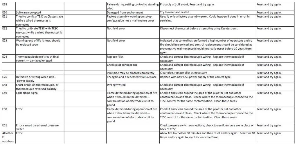
27 SPILLAGE MONITORING SYSTEM The stove is fitted with a spillage monitoring system which senses any excess temperature due to a flue restriction or blockage. In this event the gas supply is automatically turned off. Should this occur then slide the Fire control unit isolator switch to OFF (0) position and wait approximately 10 minutes for the switch to automatically reset. Re-light the stove as described in OPERATING THE STOVE section (page 19). If the stove repeatedly shuts itself off, DO NOT use the stove and have the flue system checked by a qualified person. This spillage monitoring system is not adjustable and must not be put out of action. ERROR CODES The Control unit is NOT faulty just because its shows an Error code. The Error code can be read when a wireless Control unit is paired with a Wireless enabled Remote control. The Error Code is there to enable servicing to identify what may be happening to the Control unit to cause the fire not to operate correctly. This is most likely to be environmental or one of the other components that are connected to the Control unit. If an E code is displayed, allow the fire to cool and perform a normal start attempt to reset the control to standby. Then perform a normal start attempt again to see if the fire has cleared the error and the fire is functioning correctly. If the ERROR does not clear, it is essential before undertaking any actions on the servicing as detailed below, that the batteries being used are good and should be replaced with new ones to be sure that is not the problem. Faulty batteries can cause false error codes. New batteries can be faulty too. ALWAYS CHANGE ALL THE BATTERIES TOGETHER AND NOT JUST ONE OR TWO AND ALWAYS OF THE SAME MAKE AND TYPE (I.E MANUFACTURER AND MODEL TYPE). The battery contact must be clean and there must not be any leakage from any batteries in the battery compartment or on the battery contacts. Clean thoroughly if found, they must be spotlessly clean. After replacing the batteries, to clear the error code perform a start cycle by pressing the start button as normal. Then press again in the same way to attempt a new start cycle. The error code must be cleared for the fire to function correctly. Servicing must only be carried out by competent personal that have current qualifications and accreditation (i.e. Gas safe). Page 27

28 Page 28

29 Page 29
30 Page 30
31 CLEANING Ensure that the stove is turned off before cleaning and is cold. DO NOT use abrasive cleaning agents. The stove is supplied with ceramic coals that should only be cleaned and arranged by a qualified person in accordance with the Installation Instructions. SERVICING It is essential that the stove is regularly serviced, and the flue system checked by a qualified person. Servicing Instructions The stove is fitted with a spillage monitoring system consisting of a thermal switch connected to a thermocouple interrupter. This system is not adjustable and must not be put out of action. If any parts of the spillage monitoring system require replacement only original manufacturers parts must be used. The thermal switch rating is 120 C. Quote this rating if ordering a new switch. 1. The following servicing procedure should be carried out regularly and only by a qualified person. Ensure that the fire is turned off and is cold. 2. If fitted, remove the screw securing the door handle and open the stove door. 3. Remove the ceramics in the reverse order to that described in POSITIONING THE LOGS section (p.8 & p.13). 4. Remove and deposition of dirt, lint etc. carefully from the burner flame strip, tray and pilot assembly with a soft brush. 5. Due to the intense temperatures reached in the fire, some surface cracks may appear on the ceramic components. This is quite normal and will not affect the safe operation of the fire. 6. Replace the ceramics as described in the POSITIONING THE LOGS section (p.8 & p.13). 7. Close the stove door; replace the screw securing the door handle or door. 8. Check the supply pressure as described in the TECHNICAL INFORMATION section (p.3). 9. Ensure correct operation of the flue as described in CHECK FOR SPILLAGE section (p.10). Page 31
32 10. GUARANTEE CONDITIONS OF GUARANTEE Your ESSE is guaranteed against defects arising from faulty manufacture for 2 years when supplied by an ESSE Specialist. Upon registration of the warranty, ESSE will extend the guarantee period to 5 years from purchase. Your details must be registered with us by either returning the completed warranty card or by completing registration on-line at The warranty must be registered within 1 month of installation to qualify for the 5 year warranty. The appliance must be only used for normal domestic purposes and in accordance with our instructions, be correctly installed and serviced. The guarantee does not cover: Installation Wear and tear Parts deemed to be replaceable or service parts including electrical components that may be replaced during the normal usage of the appliance. Enamel damage caused by impact, spillage, water ingress, or condensate attack from flue or by using unsuitable fuels. This guarantee is personal to the original purchaser and not transferable. Any stove or defective part replaced shall become the Company s property HOW TO PROCEED WITH A COMPLAINT If you have cause for dissatisfaction with your stove, you should first contact your ESSE dealer, who will bring your concerns to our attention. We will assess the nature of the complaint and either send replacement parts for your dealer to fit, or arrange for an ESSE engineer to inspect the appliance and carry out any work that may be deemed necessary. If the fault is not actually due to faulty manufacture but some other cause i.e. misuse, failure to install correctly, or failure to service at regular intervals, a charge will be made to cover the cost of the visit and any new parts required. SPARE PARTS Only genuine ESSE spare parts are recommended. Page 32
33 Page 33
34 Page 34
35 Page 35
36 ESSE Engineering Limited, Ouzledale Foundry, Long Ing, Barnoldswick, Lancashire BB18 6BJ Tel , Fax: Website and On-line Store Page 36
FG500 VISTA/FG525 MANUAL & REMOTE CONTROL FLUELESS GAS FIRED LOG EFFECT STOVE
 FG500 VISTA/FG525 MANUAL & REMOTE CONTROL FLUELESS GAS FIRED LOG EFFECT STOVE INSTALLATION,USER & SERVICING INSTRUCTIONS (TO BE LEFT WITH THE CUSTOMER) UK & IRELAND FG500 VISTA-LR/FG525-LR For use in UK
Intrepid 2 Intrepid 3
 Intrepid 2 Intrepid 3 Model Nos. V 10 / V10-3 NAT GAS Model Nos. V12 / V12-3 L.P.G DECORATIVE COAL EFFECT GAS STOVE USER INSTRUCTIONS This appliance is only for use on Natural Gas (G20) at a supply pressure
Harrie Leenders Fuga el - Instructions for Installation, Use and Maintenance INSTRUCTIONS FOR INSTALLATION, USE AND MAINTENANCE
 INSTRUCTIONS FOR INSTALLATION, USE AND MAINTENANCE FUGA el 1 2 1. Flue 2. Case 3. Ceramic glass 4. Aeration slide 5. Convection fins 6. Door handle 7. Base 3 4 READ THE INSTRUCTION BOOKLET AND THESE SUPPLEMENTARY
INSTRUCTIONS FOR INSTALLATION, USE AND MAINTENANCE YSEN
 INSTRUCTIONS FOR INSTALLATION, USE AND MAINTENANCE YSEN READ THE INSTRUCTION BOOKLET AND THESE SUPPLEMENTARY INSTRUCTIONS CAREFULLY BEFORE INSTALLATION These instructions together with those in the instruction
FUEL EFFECT HEATING STOVE
 No.1 Gas Stove FUEL EFFECT HEATING STOVE Installation, Maintenance & User Instructions Hand these instructions to the user Model No. PGSL**RN2 is for use on Natural Gas (G20) at a supply pressure of 20
SELECT 6 GAS STOVE. Installation and Servicing Instructions
 SELECT 6 GAS STOVE Installation and Servicing Instructions Please leave this instruction booklet with the user after the installation is complete. Leave the system ready for operation and instruct the
OWNER GUIDE. Firefox 5. Model 910. CAST-IRON GAS STOVE Fitted with a Ceramic Coal fuel effect. (GC No )
") 5122664/01 Firefox 5 Model 910 CAST-IRON GAS STOVE Fitted with a Ceramic Coal fuel effect. (GC No. 32-264-24) THIS APPLIANCE IS FOR USE WITH NATURAL GAS (G20). WHEN CONVERTED USING CONVERSION KIT NO. 0591011
5122664/01 Firefox 5 Model 910 CAST-IRON GAS STOVE Fitted with a Ceramic Coal fuel effect. (GC No. 32-264-24) THIS APPLIANCE IS FOR USE WITH NATURAL GAS (G20). WHEN CONVERTED USING CONVERSION KIT NO. 0591011
Panther - Gas Stoves OWNER S GUIDE
 Panther - Gas Stoves Model No. 553 OWNER S GUIDE This appliance meets the requirements of the European Gas Directive This guide is intended to help you care for your morsø gas stove. It gives sufficient
BALANCED FLUE LOG EFFECT STOVE
 No.1 Gas Stove BALANCED FLUE LOG EFFECT STOVE Installation, Maintenance & User Instructions Hand these instructions to the user Model No. PBFL**RN is for use on Natural Gas (G20) at a supply pressure of
Installation Instructions. Woolly Mammoth Stoves Albert Road, Braintree, Essex, CM7 3JQ
 Installation Instructions Woolly Mammoth Stoves 20-28 Albert Road, Braintree, Essex, CM7 3JQ INSTALLATION INSTRUCTIONS TO BE READ IN CONJUNCTION WITH THOSE IN THE INSTRUCTION BOOKLET These instructions
Installation & Operating Instructions. Model(s): Lincoln, Canterbury & Stamford
: Lincoln, Canterbury & Stamford") Installation & Operating Instructions Model(s): Lincoln, Canterbury & Stamford Conventionally Flued Natural Gas Stoves PLEASE LEAVE THESE INSTRUCTIONS WITH THE USER Broseley Fires do not provide flue pipes,
Installation & Operating Instructions Model(s): Lincoln, Canterbury & Stamford Conventionally Flued Natural Gas Stoves PLEASE LEAVE THESE INSTRUCTIONS WITH THE USER Broseley Fires do not provide flue pipes,
Installation and Operation Manual
 Installation and Operation Manual Winchester Gas Stove Revision: GB09b The Winchester Gas Stove Installation, Servicing and User Instructions. Technical Information Natural Gas G20/12H Propane G31/13P
INSTRUCTIONS MANUAL CAST IRON STOVE
 INSTRUCTIONS MANUAL CAST IRON STOVE CA-SGB06 Warning: Use outdoors only Read the instructions before using the appliance and retain for future reference. 1 These instructions give some important information
Installation & Operating Instructions. Model: Gas Q7 Variants Covered: Ignite 7 (CD1), Hereford 7 (CD2) & Desire 7 (SD1)
, Hereford 7 (CD2) & Desire 7 (SD1)") Installation & Operating Instructions Model: Gas Q7 Variants Covered: Ignite 7 (CD1), Hereford 7 (CD2) & Desire 7 (SD1) Conventional Flue Natural Gas Stove Top Flue Outlet Only 200747_1 PLEASE LEAVE THESE
Installation & Operating Instructions Model: Gas Q7 Variants Covered: Ignite 7 (CD1), Hereford 7 (CD2) & Desire 7 (SD1) Conventional Flue Natural Gas Stove Top Flue Outlet Only 200747_1 PLEASE LEAVE THESE
RMC1E - Variable Flame Height EASY Control
 Owner s Manual RMC1E - Variable Flame Height EASY Control General Assembly, Installation, and Operation Instructions for use with Natural Gas Burners; F, FX, CS, CXF, TNA or Propane Gas Burners: FA, FAX,
WARNING This information is a copy of an original archive, therefore Aga cannot be held responsible for its continued accuracy.
 WARNING This information is a copy of an original archive, therefore Aga cannot be held responsible for its continued accuracy. THE LITTLE WENLOCK GAS (GS1i) Users Instructions Consumer Protection Act
SPK3E - Manual EASY Control
 SPK3E - Manual EASY Control General Assembly, Installation, and Operation Instructions for use with Natural Gas Burners; F, FX, CS, CXF, TNA or Propane Gas Burners: FA, FAX, CA, CXFA, TNA/LP LISTED BY
r e - p a r t s. c o m
 Owner s Manual SPK3E - Manual EASY Control General Assembly, Installation, and Operation Instructions for use with Natural Gas Burners; F, FX, CS, CXF, TNA or Propane Gas Burners: FA, FAX, CA, CXFA, TNA/LP
Mod. MONTANA WOOD BURNING STOVE USAGE AND MAINTENANCE INSTRUCTIONS
 Mod. MONTANA WOOD BURNING STOVE USAGE AND MAINTENANCE INSTRUCTIONS Nutrients Ashes Fertilizer Wood: an ecological fuel Wood is a renewable source of energy which answers the energy and environmental demands
125SE SMOKE EXEMPT WOODBURNING STOVE INSTALLATION & USER INSTRUCTIONS (TO BE LEFT WITH THE CUSTOMER) UK & Ireland GB IE GUARANTEE
 UK & Ireland GB IE GUARANTEE") 12/09 GUARANTEE Conditions of Guarantee Your ESSE stove is guaranteed against defects arising from faulty manufacture for one year subject to the following express conditions. Failure to comply with these
12/09 GUARANTEE Conditions of Guarantee Your ESSE stove is guaranteed against defects arising from faulty manufacture for one year subject to the following express conditions. Failure to comply with these
WARNING This information is a copy of an original archive, therefore Aga cannot be held responsible for its continued accuracy.
 WARNING This information is a copy of an original archive, therefore Aga cannot be held responsible for its continued accuracy. THE COALBROOKDALE GS2i Propane Gas Model Installation and Servicing Instructions
Glammbox Crea7ion.E. GlammFire. Crea7ion by GlammFire. GlammFire
 Crea7ion by Wall Mounted Fireplaces// Glammbox 420 Glammbox 420 DF Glammbox 450 Glammbox 450 DF Glammbox 770 Glammbox 770 DF Glammbox 1150 Glammbox 1150 DF Glammbox 1600 Glammbox 1600 DF Glammbox 2150
Dry Stove Installation Guide BK545. November 2012 Rev02. EN 13240:2001+ Amd. A2:2004
 Dry Stove Installation Guide BK545 EN 13240:2001+ Amd. A2:2004 November 2012 Rev02 Please read carefully through this installation guide before proceeding with installation of the stove. Should you have
Gas Conversion Kits and Instructions
 Gas Conversion Kits and Instructions INSTALLATION FORM RGM 432/433-GC (Version D.1) Obsoletes Form RGM 432/433-GC (Version D) APPLIES TO: Model FT and Model SFT All gas conversion must be done by a qualified
INSTALLER AND OWNER GUIDE
 5118237/01 Model 0581901 Chester Log Effect Electric Stove This guide is intended to help you install and care for your Baxi Fires Division electric stove. Please read carefully before installing and using
INSTALLATION AND OPERATIONS GUIDE FOR GRAND CANYON GAS JUMBO/JUMBO SLIMLINE LOG SYSTEMS
 Burner Systems: JUMBOSLIMBRNR-24 JUMBOSLIMBRNR-30 JUMBOBRNR-36 / JUMBOSLIMBRNR-36 JUMBOBRNR-42 / JUMBOSLIMBRNR-42 JUMBOBRNR-48 / JUMBOSLIMBRNR-48 JUMBOBRNR-60 / JUMBOSLIMBRNR-60 INSTALLATION AND OPERATIONS
SINGLE BURNER STOVE IMPORTANT OPERATING INSTRUCTIONS COOKING & STORAGE POSITION PARTS IDENTIFICATION
 SINGLE BURNER STOVE OPERATING INSTRUCTIONS PARTS IDENTIFICATION Electronic Lighter Ignites the burner. Liquid Guard Holds liquid overflow. Windshield Prevents flame from being extinguished by wind. Ensures
Operator's Manual. Model: RY10MK-PRO MPN: RA-MLT Gallon Direct Fire Melter Kettle Burner Model with Adjustable Flame-Out Valve
 Operator's Manual Model: RY10MK-PRO MPN: RA-MLT-0009 10 Gallon Direct Fire Melter Kettle Burner Model with Adjustable Flame-Out Valve U.S. Patent No. 9,739,021 For Technical Support Please Visit www.rynoworx.com
The Dartmoor LOG EFFECT GAS STOVE - CONVENTIONAL FLUE SINGLE AND DOUBLE DOOR INSTALLATION, SERVICING AND USER INSTRUCTIONS
 The Dartmoor LOG EFFECT GAS STOVE - CONVENTIONAL FLUE SINGLE AND DOUBLE DOOR INSTALLATION, SERVICING AND USER INSTRUCTIONS For use in Great Britain and the Republic of Ireland (GB, IE) These instructions
Installation & Operating Instructions. Model: Gas Q7 MK2 Variants Covered: Ignite 7 (CD1), Hereford 7 (CD2) & Desire 7 (SD1)
, Hereford 7 (CD2) & Desire 7 (SD1)") Installation & Operating Instructions Model: Gas Q7 MK2 Variants Covered: Ignite 7 (CD1), Hereford 7 (CD2) & Desire 7 (SD1) Conventional Flue Natural Gas Stove Top Flue Outlet Only 200747_1TB PLEASE LEAVE
Installation & Operating Instructions Model: Gas Q7 MK2 Variants Covered: Ignite 7 (CD1), Hereford 7 (CD2) & Desire 7 (SD1) Conventional Flue Natural Gas Stove Top Flue Outlet Only 200747_1TB PLEASE LEAVE
Installation and Operating. Instructions. Multifuel Stove. Salamander. Model Lighting a solid fuel fire. 6.5 De-ashing the stove
 Installation and Operating Instructions Salamander Model 0901 Multifuel Stove Section Contents Page 1 Important information about installing and 3 using the Salamander stove 2 Unpacking the Salamander
Bloomsbury SE SMOKE EXEMPT WOODBURNING STOVE INSTALLATION & USER INSTRUCTIONS (TO BE LEFT WITH THE CUSTOMER) UK & IRELAND GUARANTEE
 UK & IRELAND GUARANTEE") 9/11 (PP) GUARANTEE CONDITIONS OF GUARANTEE Your ACQUISITIONS stove is guaranteed against defects arising from faulty manufacture for one year subject to the following express conditions. Failure to comply
9/11 (PP) GUARANTEE CONDITIONS OF GUARANTEE Your ACQUISITIONS stove is guaranteed against defects arising from faulty manufacture for one year subject to the following express conditions. Failure to comply
INSTANT GARAGE MODEL NO: CIG81224 ASSEMBLY INSTRUCTIONS PART NO: ORIGINAL INSTRUCTIONS
 INSTANT GARAGE MODEL NO: CIG81224 PART NO: 3503578 ASSEMBLY INSTRUCTIONS ORIGINAL INSTRUCTIONS GC1117 INTRODUCTION Thank you for purchasing this CLARKE Instant Garage. When erected, the CIG81224 garage
The Dartmoor LOG EFFECT GAS STOVE - CONVENTIONAL FLUE SINGLE AND DOUBLE DOOR INSTALLATION, SERVICING AND USER INSTRUCTIONS IMPORTANT
 The Dartmoor LOG EFFECT GAS STOVE - CONVENTIONAL FLUE SINGLE AND DOUBLE DOOR INSTALLATION, SERVICING AND USER INSTRUCTIONS For use in Great Britain and the Republic of Ireland (GB, IE) These instructions
Fire's Edge Fire Pit/Fire Pit Inserts For (Automated) Model 100-A
 Model 100-A") Fire's Edge Fire Pit/Fire Pit Inserts For (Automated) Model 100-A OWNER S MANUAL / OPERATING AND MAINTENANCE INSTRUCTIONS For your safety: If you smell gas: 1. Shut off gas to the appliance 2. Extinguish
Fire's Edge Fire Pit/Fire Pit Inserts For (Automated) Model 100-A OWNER S MANUAL / OPERATING AND MAINTENANCE INSTRUCTIONS For your safety: If you smell gas: 1. Shut off gas to the appliance 2. Extinguish
TUBULAR BURNER CONVERSION KIT AGCK-TBXX / AECK-UBXX
 TUBULAR BURNER CONVERSION KIT AGCK-TBXX / AECK-UBXX IMPORTANT - READ ALL INSTRUCTIONS BEFORE YOU BEGIN THE INSTRUCTIONS HEREIN SHOULD BE PERFORMED BY A QUALIFIED SERVICE TECHNICIAN. THE GRILL MUST BE COMPLETELY
700-SE Multi-Fuel & Smoke Exempt Wood Burning Stove
 700-SE Multi-Fuel & Smoke Exempt Wood Burning Stove INSTALLATION & USER INSTRUCTIONS (TO BE LEFT WITH THE CUSTOMER) UK & IRELAND GB IE CONTENTS General Safety Notes Page 2 Installing the Stove Page 11
Stockton 5 Log Effect Stove Balanced Flue
 Stockton 5 Log Effect Stove Balanced Flue With upgradeable control valve Instructions for Use, Installation and Servicing For use in GB, IE (Great Britain and Republic of Ireland) IMPORTANT This product
INSTALLATION, SERVICING AND USER INSTRUCTIONS. All instructions must be handed to the user for safekeeping
 Centurion CAST IRON FLUELESS GAS STOVE INSTALLATION, SERVICING AND USER INSTRUCTIONS All instructions must be handed to the user for safekeeping Revision A - 07/01 Country(s) of destination - GB,IE Focal
500 Range. Multi-Fuel & Smoke Exempt Wood Burning Stoves 550, 525, and 500 Vista models INSTALLATION & USER INSTRUCTIONS
 500 Range Multi-Fuel & Smoke Exempt Wood Burning Stoves 550, 525, and 500 Vista models INSTALLATION & USER INSTRUCTIONS (TO BE LEFT WITH THE CUSTOMER) UK & IRELAND GB IE CONTENTS General Safety Notes Page
Clay Adaptors & Insert Stove Kits
 Clay Adaptors & Insert Stove Kits September 2014 Tel: +353 46 95 58030 Fax: +353 46 95 58034 Email: sales@miflues.ie Web: www. miflues.ie INTRODUCTION CLAY ADAPTORS Mi-Flues Clay Adaptors are specially
Installation Instructions
 Installation Instructions For use in and IE only C i4 FS www.contura.eu 2 CERTIFICATE DECLARATION OF PERFORMANCE No. Ci4FS-CPR-130619-SE-1 PRODUCT Product type Type designation Manufacturing number Intended
BRANSDALE DOUBLE SIDED WOOD BURNING STOVE
 BRANSDALE DOUBLE SIDED WOOD BURNING STOVE INSTALLATION AND USER INSTRUCTIONS Read these instructions carefully before installation and use. These instructions should be retained by the user for future
Instructions for use, installation, and connection. Gas Built in Hob
 Instructions for use, installation, and connection Gas Built in Hob RB3311SGBS RB3312SGBS RB3311DGBS RB3311MGBS RB3311NGBS RB6313SGBST RB6323SGBST RB6314SGBS RB6313DGBST RB6313MGBST RB7312SGBS RB7313SGBST
GAS STOVE GUARD for natural gas and propane stoves
 GAS STOVE GUARD for natural gas and propane stoves OPERATING INSTRUCTIONS September 18, 2017 STOVE GUARD is not designated for use with gas stoves with pilot light. STOVE GUARD is an electronic safety
Installation and operation instructions for KINEMAX burners
 -. - Installation and operation instructions for KINEMAX burners Application requirements View port A view port to observe burner flame is essential to inspect the flame aspect. Locate the view port downstream
PROCESS BURNERS INSTALLATION, COMMISSIONING AND MAINTENANCE MANUAL HMA2A SERIES AIR HEATING BURNERS
 PROCESS BURNERS INSTALLATION, COMMISSIONING AND MAINTENANCE MANUAL HMA2A SERIES AIR HEATING BURNERS The information contained in this manual is advisory and in general terms only and does not constitute
TB131. Gas Conversion Kits for NVx & VPC Heaters. Issue 1.0 May Applies to models: NVx & VPC
 TB131 Issue 1.0 May 2018 Applies to models: NVx & VPC Gas Conversion Kits for NVx & VPC Heaters www.powmatic.co.uk +44 (0) 1460 53535 info@powrmatic.co.uk General Information Heater conversion between
700-SE Multi-Fuel & Wood Burning Stove
 700-SE Multi-Fuel & Wood Burning Stove INSTALLATION & USER INSTRUCTIONS (TO BE LEFT WITH THE CUSTOMER) Australia & New Zealand Tested to AS/NZS 4012/4013 (2014) CONTENTS General Safety Notes P 2 Installing
The four elements of nature: Fire, Water Earth & Air
 Why our flame is so natural... Our range of balanced flue gas stoves gives a beautiful lazy dancing flame pattern which emulates that of a traditional wood burning stove and with the added features of
Installation Instructions
 Installation Instructions C 710 www.contura.eu 50 CERTIFICATE Declaration of performance according to Regulation (EU) 305/2011 No. C710-CPR-160329-SE-1 PRODUCT Product type Stove lit with solid biofuels
Smoke Exempt Wood Burning Stove
 Smoke Exempt Wood Burning Stove GB IE CONTENTS General Safety Notes Page 2 Operating Instructions Page 12 Installation instructions Page 3 Wood Burning Page 14 Chimney & Flue Page 4 Solid Fuel Burning
BLOOMSBURY SE 8kW Smoke Exempt Multi-Fuel Stove
 BLOOMSBURY SE 8kW Smoke Exempt Multi-Fuel Stove INSTALLATION & USER INSTRUCTIONS (TO BE LEFT WITH THE CUSTOMER) UK & IRELAND GB IE CONTENTS General Safety Notes Page 2 Operating Instructions Page 9 Installation
200XK, 200XK DD, & 225XK Multi-Fuel & Smoke Exempt Wood Burning Stove
 200XK, 200XK DD, & 225XK Multi-Fuel & Smoke Exempt Wood Burning Stove INSTALLATION & USER INSTRUCTIONS (TO BE LEFT WITH THE CUSTOMER) UK & IRELAND GB IE CONTENTS General Safety Notes Page 2 Installing
Cassette stove installation guide
 Cassette stove installation guide BK605 EN 13229:2001 +A2:2004 Rev 04 Issue Date: 02/11/2018 Cassette stove installation guide Please carefully read through the entirety of this installation guide before
F40 Avanti. Balanced Flue Log Effect Stove. Instructions for Use, Installation and Servicing
 F40 Avanti Balanced Flue Log Effect Stove Instructions for Use, Installation and Servicing For use in GB, IE (Great Britain and Republic of Ireland) IMPORTANT This product contains a Heat resistant glass
The wall where the product will be placed must not be constructed in wood, or in any case, made of an
 Dear Client, GB We thank you for having chosen one of our products, the fruit of technological experience and of continual research for a superior quality product in terms of safety, dependability, and
SMART BIO-ETHANOL ELECTRONIC BURNER
 SMART BIO-ETHANOL ELECTRONIC BURNER User s Manual What s in the box: Smart Burner Remote Control AC Adapter Filling Hose User s Manual 1pc 1pc 1pc 1pc 1pc Preparations Remove all packaging materials prior
Read all instructions and warnings before using this fireplace. WARNING
 Frame User Manual 1 Operating Manual Thank you for purchasing this Signi Fires product. Signi Fires is very safety conscious, we have taken every care in designing, manufacturing and assembling your Signi
Dry Stove Installation Guide
 Dry Stove Installation Guide August 2017 BS EN 13240:2001 +A2:2004 CE BK545 Rev09 Arada Ltd August 2017 Please carefully read through the entirety of this installation guide before commencing installation.
MULTI-FUEL STOVE INSTALLATION AND USER INSTRUCTIONS
 PRIORY MULTI-FUEL STOVE INSTALLATION AND USER INSTRUCTIONS The Priory stove has a nominal heat output of 8Kw. and a weight of 80 kg. The flue gas mass flow is 5.4g/s for mineral fuel and 6.3g/s for wood
500 MULTI - FUEL STOVE
 02/10 (PP) INSTR.ST-500MF/u GUARANTEE CONDITIONS OF GUARANTEE Your ESSE stove is guaranteed against defects arising from faulty manufacture for one year subject to the following express conditions. Failure
INSTALLATION AND OPERATIONS GUIDE FOR GRAND CANYON GAS LOG FIRE PIT SERIES ONLY
 INSTALLATION AND OPERATIONS GUIDE FOR GRAND CANYON GAS LOG FIRE PIT SERIES ONLY Installation and service must be provided by a qualified installer, service agency or gas supplier Grand Canyon Gas Logs,
IN THE EVENT OF CHIMNEY FIRE, EVACUATE THE PROPERTY AND CALL THE EMERGENCY SERVICES.
 EKOL INSET 8 INSTALLATION AND OPERATING INSTRUCTIONS INTRODUCTION. SAFETY Safety is the most important consideration when using and installing your stove. If not installed and used correctly, a house fire
AWNING CONTROL KIT 98GCK-33B
 AWNING CONTROL KIT 98GCK-33B REV.07282015 RV AWNING PRODUCTS 1361 CALLE AVANZADO, SAN CLEMENTE, CA 92673 (800) 382-8442 FAX (949)276-5500 www.girardrv.com AC MOTOR CONTROL MODULE GC274B INSTALLATION and
Dry Stove Installation Guide July 2014
 Dry Stove Installation Guide July 2014 BS EN 13240:2001 +A2:2004 CE BK545 Rev07 Arada Ltd July 2014 Please carefully read through the entirety of this installation guide before commencing installation.
BLOOMSBURY SE INSTALLATION & USER INSTRUCTIONS. Smoke Exempt Multi-Fuel Stove (TO BE LEFT WITH THE CUSTOMER) UK & IRELAND
 UK & IRELAND") BLOOMSBURY SE Smoke Exempt Multi-Fuel Stove INSTALLATION & USER INSTRUCTIONS (TO BE LEFT WITH THE CUSTOMER) UK & IRELAND GB IE CONTENTS General Safety Notes Page 2 Operating Instructions Page 8 Installation
BLOOMSBURY SE Smoke Exempt Multi-Fuel Stove INSTALLATION & USER INSTRUCTIONS (TO BE LEFT WITH THE CUSTOMER) UK & IRELAND GB IE CONTENTS General Safety Notes Page 2 Operating Instructions Page 8 Installation
Installation & User Manual EW5000 Outdoor Cooking Fire
 Installation & User Manual EW5000 Outdoor Cooking Fire IMPORTANT: Please read this manual before installing and using the ESCEA EW5000 Cooking fire. Failure to follow these instructions may lead to a possible
How to use a multi fuel stove
 How to use a multi fuel stove Important!! When lighting the stove for the first time only a small fire should be lit. Too hot a fire will result in the paint emitting smoke - not necessarily bad but unpleasant.
WELBURN DOUBLE SIDED MULTI-FUEL STOVE
 WELBURN DOUBLE SIDED MULTI-FUEL STOVE INSTALLATION AND USER INSTRUCTIONS Read these instructions carefully before installation and use. These instructions should be retained by the user for future reference.
TC30 HEARTWOOD BURNER INSTALLATION INSTRUCTIONS
 INSTALLER: Leave this manual with the appliance. CONSUMER: Retain this manual for future reference. These instructions are supplementary to the Installation and Operating Instructions supplied with the
CONVERSION INSTRUCTIONS
 CONVERSION INSTRUCTIONS Natural Gas to Propane Gas Conversion Kit For Thermador Professional Cooktops and Ranges Model STARLPKIT Part No. 35-00-682 Contains 7mm Hex Main Orifices This kit is used to convert
Assembly/Installation/Use Instructions:
 IMPORTANT We highly recommend that our products be installed and serviced by professionals who are certified in the U.S. by NFI (National Fireplace Institute) or in Canada by WETT (Wood Energy Technical
The four elements of nature: Fire, Water Earth & Air
 Why our flame is so natural... Our range of balanced gas flue stoves gives a Beautiful Lazy Dancing flame pattern which emulates that of a traditional wood burning stove and with the added features of
Contents. Introduction...3 Description...3. Pack Contents...4. Rada Heavy Duty EV Shower Fittings Right Angled Connector (RAC)...
...") SHOWER FITTINGS PRODUCT MANUAL IMPORTANT Installer: This manual is the property of the customer and must be retained with the product for maintenance and operational purposes. Contents Introduction...3
SHOWER FITTINGS PRODUCT MANUAL IMPORTANT Installer: This manual is the property of the customer and must be retained with the product for maintenance and operational purposes. Contents Introduction...3
Installation Instructions
 Installation Instructions C 780 www.contura.eu 50 CERTIFICATE PERFORMANCE DECLARATION No. C780-CPR-130612-SE-1 PRODUCT Product type Stove lit with solid biofuels Type designation Contura 780 Manufacturing
Product instruction manual Ream Cutting Systems RE3943, RE3946, RE3947, RE3971, RE3952E
 Product instruction manual Ream Cutting Systems RE3943, RE3946, RE3947, RE3971, RE3952E The Trimfast Ream Cutters are reliable, high performance cutters that will give you the results you need quickly
Installation Instructions
 Installation Instructions C810 www.contura.eu 50 CERTIFICATE Declaration of performance according to Regulation (EU) 305/2011 No. C810-CPR-130610-SE-1 PRODUCT Product type Stove lit with solid biofuels
TCWS54 SEE THRU DIAMOND BURNER INSTALLATION KIT INSTRUCTIONS
 INSTALLER: Leave this manual with the appliance. CONSUMER: Retain this manual for future reference. These instructions are supplementary to the Installation and Operating Instructions supplied with the
INSTALLATION AND OPERATION GUIDE FOR
 INSTALLATION AND OPERATION GUIDE FOR Featuring Aquatic Glassel Tempered, Formulated Glass, 2005-2007 NATURAL GAS INSTRUCTIONS Adequate Fireplace Ventilation is Required NOTE: READ INSTRUCTIONS FULLY BEFORE
AFC-50 Automatic French Fry Cutter Instruction Manual
 AFC-50 Automatic French Fry Cutter Instruction Manual Fry Factory Inc. 67 Watts Ave, Charlottetown, PEI, C1E 2B7, Canada Phone: 902-368-2900 Fax: 902-368-8645 Email: info@fryfactoryinc.com Website: www.fryfactoryinc.com
Installation Instructions
 Installation Instructions C 556 www.contura.eu 50 CERTIFICATE PERFORMANCE DECLARATION No. C556-CPR-130601-SE-2 PRODUCT Product type Stove lit with solid biofuels Type designation Contura 556 Manufacturing
Dry stove installation guide
 Dry stove installation guide BK545 BS EN 13240:2001 +A2:2004 Rev 11 Issue Date: 07/12/2018 Dry stove installation guide Please carefully read through the entirety of this installation guide before commencing
Thermostatic Griddle Field Service Kit Instructions
 Thermostatic Griddle Field Service Kit Instructions The following document provides instructions on how to install a Garland Thermostatic Griddle Field Kit and is applicable to each 2 section of a Garland
HARROGATE WOODBURNING STOVE INSTALLATION AND USER INSTRUCTIONS
 HARROGATE WOODBURNING STOVE INSTALLATION AND USER INSTRUCTIONS Read these instructions carefully before installation and use. These instructions should be retained by the user for future reference. The
HARVIA IRON STOVE Instructions for installation and use
 HARVIA IRON STOVE EN Instructions for installation and use Harvia 10 08012014VTT Congratulations on a good choice of fireplace and thank you for your confidence in Harvia s products. Read these instructions
Capacity kw. Thermal turndown from specified maximum capacity 8:1 8:1
 3-18.3-5 Specifications of OXY-THERM TITAN burners Typical burner data Fuel: natural gas at 15 C with 10.9 kwh/nm 3 HHV - sg = 0.6 Oxygen: 90-100% purity Stated pressures are indicative. Actual pressures
100/200/700 INSTALLATION & USER INSTRUCTIONS (TO BE LEFT WITH THE CUSTOMER) UK & Ireland MULTI-FUEL STOVES GUARANTEE GB IE
 UK & Ireland MULTI-FUEL STOVES GUARANTEE GB IE") GUARANTEE 08/08 CONDITIONS OF GUARANTEE Your ESSE stove is guaranteed against defects arising from faulty manufacture for two years subject to the following express conditions. Failure to comply with these
GUARANTEE 08/08 CONDITIONS OF GUARANTEE Your ESSE stove is guaranteed against defects arising from faulty manufacture for two years subject to the following express conditions. Failure to comply with these
Alma Mons EN Owners s manual INSTALATION, ADJUSTMENT AND OPERATING INSTRUCTION
 Alma Mons Owners s manual INSTALATION, ADJUSTMENT AND OPERATING INSTRUCTION EN 12815 1 INTRODUCTION Congratulations! You have invested in energy efficient and high quality product-alma Mons wood burning
TCWS54 BLACK DIAMOND BURNER KIT INSTRUCTIONS
 INSTALLER: Leave this manual with the appliance. CONSUMER: Retain this manual for future reference. These instructions are supplementary to the Installation and Operating Instructions supplied with the
Installation Instructions
 Installation Instructions C 880 www.contura.eu 50 CERTIFICATE EC Declaration of conformity www.contura.eu Manufacturer name address Place of manufacture NIBE AB/NIBE STOVES Box 134, Skulptörvägen, SE-285
INSTALLATION AND USER INSTRUCTIONS
 WELBURN MULTI-FUEL STOVE INSTALLATION AND USER INSTRUCTIONS Read these instructions carefully before installation and use. These instructions should be retained by the user for future reference. The Welburn
TC36 CHALET II BURNER KIT INSTALLATION INSTRUCTIONS
 INSTALLER: Leave this manual with the appliance. CONSUMER: Retain this manual for future reference. These instructions are supplementary to the Installation and Operating Instructions supplied with the
INSTRUCTIONS FOR MVK-NQM PILOT KIT
 MVK-NQM IMPORTANT READ AND UNDERSTAND THESE INSTRUCTIONS BEFORE INSTALLING These instructions must be used as a supplement to the instructions supplied with your gas log set. Follow the Gas Log Set instructions
MODEL DCC DOUBLE WALL CHIMNEY CONNECTOR
 Installation & Maintenance LISTED Tested to *UL 103HT & ULC-S641 Instructions MODEL DCC DOUBLE WALL CHIMNEY CONNECTOR A MAJOR CAUSE OF CHIMNEY RELATED FIRES IS FAILURE TO MAINTAIN REQUIRED CLEARANCES (AIR
Norvik 5 Multi-fuel stove 80% Efficient
 Installation & Operating Instruction Norvik 5 Multi-fuel stove 80% Efficient This stove is designed for intermittent use and is tested and manufactured as a closed multi-fuel appliance. Cast Tec recommend
Installation Instructions
 Installation Instructions C750 C750A www.contura.eu 50 CERTIFICATE EC Declaration of conformity www.contura.eu Manufacturer name address Place of manufacture NIBE AB/NIBE STOVES Box 134, Skulptörvägen
IN THE EVENT OF CHIMNEY FIRE, EVACUATE THE PROPERTY AND CALL THE EMERGENCY SERVICES.
 Ekol Clarity 12 INSTALLATION AND OPERATING INSTRUCTIONS. INTRODUCTION SAFETY Safety is the most important consideration when using and installing your stove. If not installed and used correctly, a house
INSTRUCTIONS FOR INSTALLATION, USE AND MAINTENANCE RAIS PILAR 13 L & PILAR 13 H
 INSTRUCTIONS FOR INSTALLATION, USE AND MAINTENANCE RAIS PILAR 13 L & PILAR 13 H IMPORTANT INFORMATION On first lighting the stove you must be careful not to touch the painted surfaces and it is MOST IMPORTANT
EXCEL ULTRABlack FS 6 Clearance Connector INSTALLATION AND MAINTENANCE INSTRUCTIONS
 EXCEL ULTRABlack FS 6 Clearance Connector INSTALLATION AND MAINTENANCE INSTRUCTIONS A MAJOR CAUSE OF CHIMNEY RELATED FIRES IS FAILURE TO MAINTAIN REQUIRED CLEARANCES (AIR SPACE) TO COMBUSTIBLE MATERIALS.