Installation and Operation Manual
|
|
|
- Leslie Morrison
- 6 years ago
- Views:
Transcription


1 Installation and Operation Manual Winchester Gas Stove Revision: GB09b
2 The Winchester Gas Stove Installation, Servicing and User Instructions. Technical Information Natural Gas G20/12H Propane G31/13P Heat Input (Gross) 6.9 Kw/Hr 6.9Kw/Hr Supply Pressure 20 Mbar 37 Mbar Gas Rate 0.66 M3/Hr 0.25 M3/Hr Injector Size C.A.T. 18/460 C.A.T. 18/200 Contents Arranging the layout of the coals/logs 7-10 Dimensions and Details 2 Extinguishing the stove fully 11 Flue Connection 5 Gas Connection 6 Guarantee Out side the back cover Igniting the permanent pilot light 11 Important information 3 Note to the installation engineer 12 Operating the stove 11 Pressure testing 6 Paint curing 14 Remote control Separate Sheet Servicing Instructions 13 Sitting the appliance 4 Spillage monitoring system 12 Stove assembly 4 Test for Spillage 12 Troubleshooting 13 Ventilation 6 Broseley Fires Ltd Knights Way Battlefield Enterprise Park Shrewsbury SY1 3AB United Kingdom Telephone +44(0) Fax +44(0)
3 Winchester Gas Dimensions Height Height to centre of rear flue spigot Depth Width Centre of top flue to rear of stove Flue spigot diameter Weight Maximum heat output (approx.) 595mm 455mm 465mm 590mm 150mm 127mm 116kg 5.6 Kilowatts
4 THANK YOU FOR PURCHASING A GAS FIRED STOVE Broseley Fires Ltd, a family run company, was founded as an appliance and design development company in Since then we have built up an enviable reputation for the quality, reliability and fuel efficiency of our stoves. These instructions have been carefully prepared to guide the installer and end-user through the relevant methods and standards for installation of your new Gas Stove. Correctly installed and operated, your stove will give you many years of warmth and reliability. Therefore, we would suggest that you read the whole instruction manual prior to handing it to your installer. That way you will have a clearer picture of what is involved. IMPORTANT INFORMATION APPLIANCE TO BE INSTALLED IN ACCORDANCE WITH NATIONAL REGULATIONS 1. The stove is designed to run on either natural gas or LPG. The burner units are not interchangeable between the two types of gas. This stove is a radiant convector fuel-effect appliance. The site of the stove i.e. the chimney, flue and hearth etc., must comply with the current building regulations and codes of practice before the stove is installed (see sitting the appliance). 2. It is required by law that the complete assembly, installation and commissioning of gas-fired stoves is carried out by a professionally qualified and accredited gas fitter who is registered on the gas safe register DO NOT ATTEMPT TO INSTALL THIS APPLIANCE YOURSELF. Broseley Fires Ltd takes no responsibility for any breach of the legal standards prevailing as far as the fitting of this appliance is concerned. 3. The stove is an efficient appliance, giving off convected conducted and radiated heat. All surfaces of the stove except the control knob are considered to be working surfaces. Adequate precautions should always be taken to protect children, the elderly, the infirm and pets etc. from coming into contact with the stove. 4. Ensure that the local gas distribution conditions, the nature of the gas pressure are compatible with the data plate fitted between the right hand legs and on the control valve. These instructions have been compiled in accordance with BS5258 part 12:1986. The Gas Safety Installation and Use Regulations The Building Regulations (issued by the Department of the Environment) The Building Standards (Scotland) (Consolidation) Regulations.
5 SITTING THE APPLIANCE The gas supply connection to the appliance is at the rear right hand side. The connection requires an 8mm-diameter semi-rigid pipe, not more than 1 metre in length. The appliance can be installed in any adequate area suitable for solid fuel fires and stoves. It can use a class 1, class 2 and pre-cast flue. To ensure maximum and efficient use of the stove, we recommend the following hearth specifications. The hearth must be at least 300mm at any angle in front of the incandescent heat source (the burner surface) and the burner surface requires a clearance of 150mm each side. The effect of this will mean the hearth must extend about 200mm in front of the legs of the stove. The hearth must be made of non-combustible material at least 12 millimeters thick. On all installations, no combustible material such as carpet should cover the hearth. To prevent this from happening, the hearth should be at least 50mm above the level of the floor. If this is not possible, a fender/kerb of a similar height should be placed around the edge of the hearth. If the appliance has to be located in an opening, there must be a clearance of a minimum of 100mm each side of the stove. The rear of the appliance should have a minimum 75mm air gap between the stove and the back wall. There must be a minimum clearance of 610mm from any combustible surface. i.e. skirting board or beams. Stove Assembly Please check that the following components are included before you start on the assembly: Stove Box 1 x cast iron stove body 1 x flue spigot 1 x flue spigot blanking disc (for blanking unused flue outlet) Burner Box 1 x burner unit 1 x instruction booklet 2 x burner fixing brackets and screws 2 x burner retaining bolts with nuts 1 x remote control unit with plug-in sensor unit Ceramic Box Coal Option See page 9 Log Option See page 10/11.
6 Before installing the stove ensure the gas to be used i.e. natural (mains) gas or LPG corresponds with the identification plate on the burner. Unscrew the door handle and open the main stove door. With the burner out of the stove, screw the two burner fixing brackets to the rear of the burner so that the U slot faces upwards and locates with the screw holes in the internal rear plate. Next, with the stove stood upright insert the burner (control first) through the door. Dip the controls through the bottom of the stove so that the burner comes to rest onto the brackets located at the front. Fix using nuts and bolts provided. The U sections on the burner fixing brackets will then line up with the two holes located on the internal rear plate. Finally screw the two screws and washers provided through the U sections to hold the burner securely in place against the rear plate. Flue Connection The stove must be installed in accordance with current gas and buildings regulations BS5871: Part1. Before you install the stove, make sure the chimney flue outlet is correctly positioned to align with the flue outlet on the stove and that the chimney is in good condition. If not, a chimney liner must be installed or a suitable class II gas flue used. A draught is necessary to ensure the products of combustion are fully evacuated. Due to the internal dilution/diversion system in the stove, it is not obligatory to line the chimney but local conditions will apply. The flue will have to be inspected by a CORGI registered installer and passed as suitable/sound. The Gas Stove is suitable for both Class I & II and pre-cast flues (The Building Regulations 2000). The stove can be installed as a top or rear outlet without any additional parts. Ideally it is recommended that a minimum height of 610mm from the stove should be established before any significant changes of the direction of the flue. Horizontal or negative gradients should be avoided. The flue must have a minimum height of 3 metres to insure adequate draught. Prior to installation, the installer should insure that the flue is free from obstruction and any dampers must be fixed in a permanently open position. Ensure the chimney is not closed and that it has been swept and subsequently smoke tested. Make sure that rain, birds or any foreign body cannot get into the chimney to cause damage or blockage. This problem can normally be overcome by fitting an approved gas cowl. It is essential for the effective running of your stove that the chimney draws properly to allow the products of combustion to escape.
7 VENTILATION (GB ONLY) The gas stove is rated at less than 7kw and therefore does not normally require additional ventilation in the room (BS5871 part II). GAS CONNECTION A minimum 15mm-diameter gas supply pipe must be used to within 1 metre of the installation with the final connection to the stove to be completed with the suitable 8mm semi-rigid gas pipe. The 8mm pipe should be connected to the inlet of the gas valve using the nut and 8mm olive provided. Support the control whilst finally tightening the supply pipe. A gas safety tap/restrictor elbow with a pressure test point at the inlet to the burner is provided. PRESSURE TESTING Always make sure that there is adequate gas pressure and volume to the stove. The relevant pressures are on the ID plate on the gas control knob. 1. For natural gas, this is 20mbar measured at the burner test nipple situated at the inlet connection to the stove with the appliance in the full rate position. 2. For propane, this is 37mbar measured at the burner test nipple situated at the inlet connection to the stove with the appliance in the full rate position. 3. Ensure that the gas pressure to the stove is maintained when it is operating at the same time as other appliances in the building and that a suitable pressure gauge is used i.e. a manometer. Any service call as a result of incorrect gas pressure will be chargeable. ARRANGING THE LAYOUT OF THE CERAMICS Only the ceramics supplied with this appliance should be used. The ceramics should only be laid as described. Replacement ceramics are available from your dealer. Whilst arranging the ceramics, ensure that the pilot is not obstructed. Broseley Fires Ltd accepts no responsibility for any injury sustained whilst handling hot ceramics. Before any ceramics are placed in position ensure that the burner is operating correctly. The flames should be fairly even across the burners mesh top. Ceramics which are found to be placed other than in accordance with these instructions will result in a charge being made following any service callout.
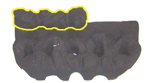
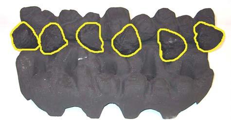
8 COAL LAYOUT Warning: Ceramic coals are very fragile so always handle with care when fitting them. Follow these instructions carefully. Ceramics that are positioned wrongly could seriously alter the performance of your appliance. Step 1 Open the door fully, you may wish to lift it from its hinges. Take the large base ceramic coal matrix making sure the front edge is facing towards you. Pick up the ceramic with both hands, placing the fingers gently through the flame holes. Support the weight at all times as the ceramics are fragile and damage easily. During the placement do not force the ceramic into position as it will break. Turn the front edge of the ceramic to face downwards and insert the right hand side first into the rear right corner of the stove. It should now be possible to gently follow with the left hand and at the same time rotate the ceramic upwards so that it lays flat on the burner. The ceramic should be against the back of the stove and central about the burner mesh. Step 2 Take the larger of the rear ceramic (left hand side) and locate it into position on the base ceramic via the location holes and lugs. Ensure the flat rear side of the ceramics is against the back of the stove. Step 3 Take the smaller of the rear ceramics (right hand side) and locate it into position on the base ceramic via the location holes and lugs. Ensure the flat rear side of the ceramic is against the back of the stove. The two rear pieces fit together. Step 4 Place the 6 loose coals across the centre of the fire, so that they bridge the gap between the rear and base ceramics. These coals should be rested gently in position. Do not push them into the gap, as this will prevent the flames from burning evenly and effectively. The path of the flame should not be obstructed. IMPORTANT Please follow these instructions carefully. Ceramics that are positioned wrongly could seriously alter the performance of your appliance.


9 Winchester Coal Fitting Instructions Stage 1 Stage 2 Stage 3 Stage 4


. This log also has two location points.")

10 Log Ceramic Fitting Instructions THE CERAMIC LOGS AVE LOCATION POINTS ON THEM THAT WILL HELP YOU LOCATE THEM IN THE CORRECT POSITION. PLEASE READ THE FOLLOWING INSTRUCTIONS CAREFULLY AND USE THE DIAGRAMS TO ASSIST YOU. Stage 1 Position the largest ceramic on top of the burner and push it firmly against the rear of the stove. Insure that it is central about the burner. Stage 2 Position the rear log onto the two location lugs towards the rear of the base ceramic as shown in the diagram. Stage 3 Position the next log as shown in the diagram (below). This log also has two location points. Stage 4 This log is located on a lug that has been formed on top of the previous log. Locate this lug first, the other end of the log is a notched out section in the base ceramic. Stage 5 This log is located on a lug that has been formed on top of the rear log. Please make sure that this log and all others are in position, exactly as shown in the diagrams.
11 OPERATING THE STOVE It is important to read these instructions thoroughly before lighting the stove. The gas stove operates with a traditional permanent pilot light. The knobs for ignition and power control are located on the lower right hand side of the stove. The pilot light is located at the front middle of the coal matrix. If the Flame Supervision Device Actuating Flame (the pilot light) is extinguished by intention or not, no attempt should be made to re-light until 3 minutes have elapsed. IGNITING THE PERMANENT PILOT LIGHT 1. Depress the rear control knob fully. 2. Whilst depressed, turn knob sharply 90 degrees anti-clockwise to pilot setting. Repeat until pilot light is visibly lit. You should fell some resistance and hear a click. Repeat until the pilot lights. 3. Keep knob depressed at this point for seconds. 4. Upon releasing, turn the knob anti-clockwise until it stops in the permanent pilot light position. The permanent pilot light will remain lit. This is the position for remote operation and can be left with the pilot running. You may wish to turn off the stove during long periods of non-use perhaps during the summer months. SEE SEPARATE INSTRUCTIONS FOR RUNNING THE STOVE UNDER REMOTE CONTROL. In the event of a failure of the remote control, the front control valve can be adjusted manually by rotating between the high and low positions. EXTINGUISHING THE STOVE FULLY 1. From any heat setting or the permanent pilot, depress the rear control knob and turn clockwise to OFF position. Should the glass door become broken or damaged in any way, turn your stove off and do not attempt to re-light it. Contact your dealer for a replacement to be fitted before relighting the appliance. PLEASE EXPLAIN TO THE CUSTOMER THESE LIGHTING AND EXTINGUSIHING PROCEDURES AND THAT IT IS NORMAL FOR THE STOVE TO GIVE OFF ODOURS WHILST THE PAINT, SEALANT AND CAST IRON MATURES.

12 THE REMOTE CONTROL POSITIONING THE RECEIVER After fitting the batteries in the receiver and the hand set, place the receiver anywhere on the hearth. There is a long lead on the receiver to allow you to position the receiver towards the front of the hearth, if you wish to see the light come on when the handset is in use. Place the lead on the hearth also. Failure to do this will cause malfunction of the unit. OPERATING INSTRUCTIONS FOR G30-ZRPTT REMATE CONTROL Caution! Read these instructions entirely before use. G30-ZRPTT remote controls must be installed and operated according to all locally applicable regulations! G30-ZRPTT Remote Controls are designed for use only in gas fires equipped with specially designed combination controls (GV34 or GV36 retrofitted with a motor) produced by Mertik Maxitrol. Due to the integrated thermostat, the G30- ZRPTT is not to be used with open gas fires! Technical Data Ultrasound Transmission Range: m ft. Frequency: ON 40,5kHz, OFF 40kHz Ambient Temperature Transmitter & Receiver max. 60 C 140 F Connecting Cables: max. 180 C 356 F Batteries Handset: 1 x 9V block (alkaline recommended) Receiver: 4 x 1,5V AA (alkaline recommended) Connections The G30-ZRPTT is intended for use only with motorized gas combination controls models GV34 (or GV36 retrofitted with a motor). The receiver cable must be firmly plugged onto the flat blade connectors (motor: 6,3 and 4,8mm; micro switch: both 2,8mm, see llustration 2). A B
 to C (and 24 hour clock) or vice versa.")

13 Transmitter Function Set the Display After connecting the battery or by simultaneously pressing AUTO and TIMER, the display flashes. You are in set mode. From set mode, press AUTO to switch from F (and 12 hour clock) to C (and 24 hour clock) or vice versa. The display will automatically return to manual mode after some time, but you may immediately return to manual by depressing the TIMER button. Set the current Time After connecting the battery or by simultaneously pressing AUTO and TIMER, the display flashes. You are in set mode. From set mode, press (p) to set the hour and (q) to set the minute. Wait or press TIMER to return to manual mode. Programming the Desired Set Temperature Press AUTO until the display flashes. Press (p) or (q) to set the desired temperature. Wait or press AUTO to switch to automatic mode. A sensor in the transmitter measures the room temperature. The controller compares the room temperature with the set temperature and sends a signal to the receiver to turn the gas valve motor, which adjusts the flame height accordingly. Programming the Timer Press TIMER until P1* flashes (period 1, heating cycle on). Set the time for the beginning of the first heating period by pressing (p) for hour and (q) for minute. Press TIMER again; P1w appears. Illustration 2: Cover with Connectors for Micro Switch TIMER AUTO (Programming the Timer) Set the time for the end of the first heating period. Press TIMER again to set the second heating period P2* (heat on) and P2w (heat off). Store both heating periods by pressing TIMER again. If only one heating period is desired, program the same time for P2* and P2w. Manual Mode (MAN in display) for Manual Flame Height Adjustment Press (p) to turn on the fire (main burner) or to increase flame height Press (q) to decrease flame or to turn down to pilot. To incrementally increase or decrease the flame height lightly tap either the (p) or (q) button. The send symbol appears in the upper left corner of the display when either button is depressed. The LED of the receiver flashes when knob B of the valve reaches its end stops. Automatic Mode (AUTO in display) for Temperature Control
14 Briefly press AUTO. The set temperature will appear briefly before the display reverts to the room temperature. Timer Mode (TIMER in display) During heating periods P1* and P2*, the temperature is controlled in the same manner as in automatic mode. When the timer program turns to w (heating cycle off), the motor will turn the valve to pilot and there is no temperature control. This minimizes battery consumption. You may press AUTO to verify the set-temperature and then press TIMER to return to timer mode. You may press either the (p) or (q) button from any mode for manual override. To prolong battery life, we recommend switching the transmitter to manual mode and turning the fire to pilot with the (q) button before turning the appliance off. If the transmitter is left in automatic or timer mode, the batteries will continue to be used when the appliance is off. Changing the Battery If BATT appears in upper right hand corner of the display or if the LED of the receiver becomes faint, please change the battery from transmitter or receiver. If the batteries lose power, the flame height can be adjusted by manually turning knob B (see illustration 2). Note Please note, the placement of the transmitter (temperature sensor) is important to assure proper temperature regulation. Generally, a more contstant temperature will be assured, if the transmitter is not too far from the gas appliance. Before switching to AUTO or TIMER mode, press either button (p) or (q) to verify the reception (when the send symbol appears in the transmitter display, the receiver s LED must illuminate). For the AUTO or TIMER mode to function correctly, the transmitter must remain within range of the receiver. The transmitter should not be used in very close proximity to the receiver (less than 1m / 3ft) as this could, in very rare cases, produce a electronic switching error. This error could block the motor when the knob reaches the end points of its turning radius. The knob must then be turned manually to free the blockage. The temperature is controlled by activating the motor for a specific length of time to adjust the appropriate flame height. This time is calculated by the transmitter and depends on variables such as room size, heater capacity, battery power, etc. Therefore, a few cycles are necessary before an optimum is achieved. If a low flame is sufficient to provide enough warmth to the room, then the appliance will cycle between low fire and off. This allows longer periods with the flame on and provides a more uniform room temperature. NOTE TO THE INSTALLATION ENGINEER Please make sure the customer is familiar with the initial lighting and operating procedures before leaving the site and that this instruction booklet is left with them when the final commissioning is complete.
15 TEST FOR SPILLAGE A Spillage Test MUST be made before the installed fire is left with the customer. Carry out the test by first closing all doors and windows in the room containing the fire. Insure that the fire is burning at full rate for a minimum of minutes. Using a lighted smoke match, run along under the rear edge of the stove. The draught diverter box is situated centrally, the entry being in the rear panel for the stove. Observe the smoke being drawn into the dilution box. After 10 minutes repeat the test. If there is an extractor fan in a nearby room the spillage test must be repeated with the fan running and all connecting doors between the fire and fan left open. If there are still problems, the chimney / flue may require attention. Disconnect the stove and seek expect advice. SPILLAGE MONITORING SYSTEM This appliance is fitted with an atmospheric sensing spillage monitoring system, in the form of an oxygen depletion-sensing pilot. This is designed to shut down the fire within a safe period if there is an excessive build up of products of combustion within the room space. This would usually only occur if the flue path suffered severe blockage and / or ventilation was severely impeded. THE FOLLOWING ARE IMPORTANT WARNINGS RELATIVE TO THE SPILLAGE MONITORING SYSTEM 1. The installer must not attempt any adjustments to the spillage monitoring system. 2. There must be no attempt to disable the spillage monitoring system. 3. It is not possible to replace individual parts of the pilot assembly on the appliance only a complete pilot assembly (including thermocouple) may be fitted in the event of a replacement being necessary. When the spillage monitoring system is replaced, only complete and original manufactures parts may be fitted. 4. Should the appliance turn itself off, wait for a minimum of 3 minutes before attempting to re-light. In the event of your stove tripping out, consult your installation engineer to have the flue / chimney checked.
16 TROUBLESHOOTING THE GAS PILOT WILL NOT IGNITE OR STAY LIT Ensure the gas is turned on at the appliance and the meter / cylinder. Hold the pilot gas button for at lest 20 seconds once the pilot is alight to ensure the operation of the safety thermocouple valve. Ensure that the pilot injector is not obstructed or blocked and it is free from any dust or dirt. Ensure that the thermocouple has not been damaged in transit. This is a very delicate device. On bottled gas (LPG), check that the cylinder is not empty. Ensure that the aeration ring shutter on the pilot head is fully open so that the pilot flame is initially intense: this can be subsequently turned down. Ensure the pilot flame is the correct size for the type of gas. The flame should be focused on the thermocouple probe, so that it is evenly encircled. The pilot should have 3 flames. One directed towards the thermocouple, one towards the bed of the fire and the third towards the ignitor valve. Any whistling sound you hear is normally caused by dirt obstructing the pilot. This is normally cured by carrying out the cleaning process outlined in the next section entitled Servicing Instructions. After altering the pilot, check for any leakage of gas THE MAIN BURNER DOES NOT SEEM TO BURN CORRECTLTY Ensure there is adequate gas pressure to the appliance. The pressure can be obtained by unscrewing the pressure test nipple and applying a suitable pressure gauge (I.E. A MANOMETER). Be sure that the gas pressure agrees with the identification label on your stove. Ensure adequate volume of gas is being used. Once the fire is burning on maximum, turn off all other gas appliances in the house and calculate the fuel being burned from the gas meter. See that the burner is burning evenly across the whole of the mesh surface without any coals in place. SERVICING INSTRUCTIONS Servicing should be carried out annually by a qualified installation engineer when the stove is cold and the gas supply is turned off at the isolation tap. The following points should be checked. Remove the coals and clean any dust and debris from the top of the burner unit. Ideally a vacuum cleaner should be used, but a soft brush will do. Check the condition of the coals. Any damaged ones will affect the efficient operation of the stove and should be replaced with new ones available from your stove supplier.
17 All gas supply joints should be checked to make sure they are completely sealed and that the gas supply and pressure is to specification. The pilot jets are correctly set and clear of obstruction. The chimney should also be checked to make sure there are no restrictions or blockages. Finally re-lay the coals and re-light the stove as described previously. CURING THE PAINT Most high temperature paints operate in the same way. They use a resin which dries at room temperature and a silicon resin which cures at high temperatures. When the stove is burned the dry resin burns away and the silicon cures. This transition occurs about 475 degrees F. After the stove burns about three times, the entire surface which gets hot will have cured. The house needs to be fully ventilated during these initial burnings and although the smoke is mostly Carbon Dioxide there are other components of the smoke which make it smell bad and may irritate some people. These problems will go away after the first few burns depending of the duration and surface temperature of each burn. The hotter the stoves gets the more it will cure. AND FINALLY.. We would remind you that it is a legal requirement that the stove is installed by a qualified and accredited installation engineer. Improper installation, adjustment, alteration, service or maintenance can cause personal injury and / or damage to property. If you are in the slightest doubt about any aspect of your stove s performance or you require additional information then please contact your stove supplier, a qualified installation engineer or call our technical help-line on Please do not store, keep or use petrol or any other flammable liquids, vapours or substances anywhere near the stove or any other heating appliance. We hope these instructions are clear and helpful and you are able to enjoy the full benefits of your stove. Please keep this booklet handy for future reference. The materials used in building your gas stove are guaranteed for one year provided the assembly and operation complies with these instructions. Accidental damage and all consumables including the glass door seal are not covered. We are sure you will appreciate and accept that our guarantee cannot be extended to cover the assembly, installation and the use of your stove as these are all operations outside our control or influence. Please retain your purchase receipt. We will need to see this in the event of a claim under warranty.
18 STOVE INSTALLATION SPECIFICATION & INFORMATION THIS SECTION TO BE COMPLETED AND SIGNED BY THE INSTALLATION ENGINEER TYPE OF GAS SUPPLY (please tick) Natural (mains) Gas LPG supply in bulk LPG supply in cylinder Size of Governor setting (i.e. Natural Gas 20 mbar. LPG 37 mbar) Length and size of gas supply Meter pressure. Fire on only Other appliances. All on Burner pressure. Fire on only Other appliances. All on Gas rate Natural Gas Time for 1 cubic foot in seconds Type and size of flue Approx. height Is a register plate fitted? How much area of flue is left? Is there any spillage? Is the draught excessive? Is there any ventilation in the room? Has the room double-glazing? Is the door close fitting? Has the pilot sufficient heat to open the FFD? Is the aeration of the pilot correct? Is the FFD phial in the correct position in the pilot flame? Does the flame encircle the FFD? Installation Engineers Name Address Telephone Fax Mobile Corgi registered? Yes No Number Signed Date
19 Guarantee Dear Customer, Your decorative gas fire, when installed in accordance with the installation instructions and operated in accordance with these instructions should provide many years of safe and efficient operation. We thank you for purchasing our product and trust it will provide excellent service. This appliance carries a guarantee of 1 year. The consumable components of this appliance are guaranteed for one year. We agree to repair free of charge or, at our option, replace the appliance or part thereof, which may prove to be defective within the guarantee period. The guarantee is void if: The appliance is not installed and operated in accordance with our instructions; or The appliance is not serviced, by a CORGI registered engineer, annually; or Repairs of modification have been carried out by the purchaser or any third party not authorized by us; or The appliance has been misused or accidentally damaged; or Damage is due to fair wear and tear ; or The appliance or defective component(s) are not returned to us, prepaid postage. The rights given in this guarantee are limited to the UK mainland and are in addition to any to which you may have a statutory entitlement. Please retain your purchase receipt. We will need to see this in the event of a claim under warranty. Broseley Fires Ltd Knights Way Battlefield Enterprise Park Shrewsbury SY1 3AB Telephone + 44 (0) Fax + 44 (0)
Installation & Operating Instructions. Model(s): Lincoln, Canterbury & Stamford
: Lincoln, Canterbury & Stamford") Installation & Operating Instructions Model(s): Lincoln, Canterbury & Stamford Conventionally Flued Natural Gas Stoves PLEASE LEAVE THESE INSTRUCTIONS WITH THE USER Broseley Fires do not provide flue pipes,
Installation & Operating Instructions Model(s): Lincoln, Canterbury & Stamford Conventionally Flued Natural Gas Stoves PLEASE LEAVE THESE INSTRUCTIONS WITH THE USER Broseley Fires do not provide flue pipes,
Installation & Operating Instructions. Model: Gas Q7 Variants Covered: Ignite 7 (CD1), Hereford 7 (CD2) & Desire 7 (SD1)
, Hereford 7 (CD2) & Desire 7 (SD1)") Installation & Operating Instructions Model: Gas Q7 Variants Covered: Ignite 7 (CD1), Hereford 7 (CD2) & Desire 7 (SD1) Conventional Flue Natural Gas Stove Top Flue Outlet Only 200747_1 PLEASE LEAVE THESE
Installation & Operating Instructions Model: Gas Q7 Variants Covered: Ignite 7 (CD1), Hereford 7 (CD2) & Desire 7 (SD1) Conventional Flue Natural Gas Stove Top Flue Outlet Only 200747_1 PLEASE LEAVE THESE
Installation & Operating Instructions. Model: Gas Q7 MK2 Variants Covered: Ignite 7 (CD1), Hereford 7 (CD2) & Desire 7 (SD1)
, Hereford 7 (CD2) & Desire 7 (SD1)") Installation & Operating Instructions Model: Gas Q7 MK2 Variants Covered: Ignite 7 (CD1), Hereford 7 (CD2) & Desire 7 (SD1) Conventional Flue Natural Gas Stove Top Flue Outlet Only 200747_1TB PLEASE LEAVE
Installation & Operating Instructions Model: Gas Q7 MK2 Variants Covered: Ignite 7 (CD1), Hereford 7 (CD2) & Desire 7 (SD1) Conventional Flue Natural Gas Stove Top Flue Outlet Only 200747_1TB PLEASE LEAVE
Intrepid 2 Intrepid 3
 Intrepid 2 Intrepid 3 Model Nos. V 10 / V10-3 NAT GAS Model Nos. V12 / V12-3 L.P.G DECORATIVE COAL EFFECT GAS STOVE USER INSTRUCTIONS This appliance is only for use on Natural Gas (G20) at a supply pressure
SELECT 6 GAS STOVE. Installation and Servicing Instructions
 SELECT 6 GAS STOVE Installation and Servicing Instructions Please leave this instruction booklet with the user after the installation is complete. Leave the system ready for operation and instruct the
Dry Stove Installation Guide BK545. November 2012 Rev02. EN 13240:2001+ Amd. A2:2004
 Dry Stove Installation Guide BK545 EN 13240:2001+ Amd. A2:2004 November 2012 Rev02 Please read carefully through this installation guide before proceeding with installation of the stove. Should you have
Panther - Gas Stoves OWNER S GUIDE
 Panther - Gas Stoves Model No. 553 OWNER S GUIDE This appliance meets the requirements of the European Gas Directive This guide is intended to help you care for your morsø gas stove. It gives sufficient
INSTRUCTIONS MANUAL CAST IRON STOVE
 INSTRUCTIONS MANUAL CAST IRON STOVE CA-SGB06 Warning: Use outdoors only Read the instructions before using the appliance and retain for future reference. 1 These instructions give some important information
Harrie Leenders Fuga el - Instructions for Installation, Use and Maintenance INSTRUCTIONS FOR INSTALLATION, USE AND MAINTENANCE
 INSTRUCTIONS FOR INSTALLATION, USE AND MAINTENANCE FUGA el 1 2 1. Flue 2. Case 3. Ceramic glass 4. Aeration slide 5. Convection fins 6. Door handle 7. Base 3 4 READ THE INSTRUCTION BOOKLET AND THESE SUPPLEMENTARY
INSTRUCTIONS FOR INSTALLATION, USE AND MAINTENANCE YSEN
 INSTRUCTIONS FOR INSTALLATION, USE AND MAINTENANCE YSEN READ THE INSTRUCTION BOOKLET AND THESE SUPPLEMENTARY INSTRUCTIONS CAREFULLY BEFORE INSTALLATION These instructions together with those in the instruction
Gas Conversion Kits and Instructions
 Gas Conversion Kits and Instructions INSTALLATION FORM RGM 432/433-GC (Version D.1) Obsoletes Form RGM 432/433-GC (Version D) APPLIES TO: Model FT and Model SFT All gas conversion must be done by a qualified
IN THE EVENT OF CHIMNEY FIRE, EVACUATE THE PROPERTY AND CALL THE EMERGENCY SERVICES.
 EKOL INSET 8 INSTALLATION AND OPERATING INSTRUCTIONS INTRODUCTION. SAFETY Safety is the most important consideration when using and installing your stove. If not installed and used correctly, a house fire
Installation and Operating. Instructions. Multifuel Stove. Salamander. Model Lighting a solid fuel fire. 6.5 De-ashing the stove
 Installation and Operating Instructions Salamander Model 0901 Multifuel Stove Section Contents Page 1 Important information about installing and 3 using the Salamander stove 2 Unpacking the Salamander
OWNER GUIDE. Firefox 5. Model 910. CAST-IRON GAS STOVE Fitted with a Ceramic Coal fuel effect. (GC No )
") 5122664/01 Firefox 5 Model 910 CAST-IRON GAS STOVE Fitted with a Ceramic Coal fuel effect. (GC No. 32-264-24) THIS APPLIANCE IS FOR USE WITH NATURAL GAS (G20). WHEN CONVERTED USING CONVERSION KIT NO. 0591011
5122664/01 Firefox 5 Model 910 CAST-IRON GAS STOVE Fitted with a Ceramic Coal fuel effect. (GC No. 32-264-24) THIS APPLIANCE IS FOR USE WITH NATURAL GAS (G20). WHEN CONVERTED USING CONVERSION KIT NO. 0591011
RMC1E - Variable Flame Height EASY Control
 Owner s Manual RMC1E - Variable Flame Height EASY Control General Assembly, Installation, and Operation Instructions for use with Natural Gas Burners; F, FX, CS, CXF, TNA or Propane Gas Burners: FA, FAX,
Thermostatic Griddle Field Service Kit Instructions
 Thermostatic Griddle Field Service Kit Instructions The following document provides instructions on how to install a Garland Thermostatic Griddle Field Kit and is applicable to each 2 section of a Garland
G500 VISTA/G525 MANUAL & REMOTE CONTROL GAS FIRED LOG EFFECT STOVE
 G500 VISTA/G525 MANUAL & REMOTE CONTROL GAS FIRED LOG EFFECT STOVE INSTALLATION,USER & SERVICING INSTRUCTIONS (TO BE LEFT WITH THE CUSTOMER) UK & IRELAND G500 VISTA-LR/G525-LR For use in UK & Ireland on
WARNING This information is a copy of an original archive, therefore Aga cannot be held responsible for its continued accuracy.
 WARNING This information is a copy of an original archive, therefore Aga cannot be held responsible for its continued accuracy. THE LITTLE WENLOCK GAS (GS1i) Users Instructions Consumer Protection Act
r e - p a r t s. c o m
 Owner s Manual SPK3E - Manual EASY Control General Assembly, Installation, and Operation Instructions for use with Natural Gas Burners; F, FX, CS, CXF, TNA or Propane Gas Burners: FA, FAX, CA, CXFA, TNA/LP
The four elements of nature: Fire, Water Earth & Air
 Why our flame is so natural... Our range of balanced flue gas stoves gives a beautiful lazy dancing flame pattern which emulates that of a traditional wood burning stove and with the added features of
SINGLE BURNER STOVE IMPORTANT OPERATING INSTRUCTIONS COOKING & STORAGE POSITION PARTS IDENTIFICATION
 SINGLE BURNER STOVE OPERATING INSTRUCTIONS PARTS IDENTIFICATION Electronic Lighter Ignites the burner. Liquid Guard Holds liquid overflow. Windshield Prevents flame from being extinguished by wind. Ensures
SPK3E - Manual EASY Control
 SPK3E - Manual EASY Control General Assembly, Installation, and Operation Instructions for use with Natural Gas Burners; F, FX, CS, CXF, TNA or Propane Gas Burners: FA, FAX, CA, CXFA, TNA/LP LISTED BY
INSTANT GARAGE MODEL NO: CIG81224 ASSEMBLY INSTRUCTIONS PART NO: ORIGINAL INSTRUCTIONS
 INSTANT GARAGE MODEL NO: CIG81224 PART NO: 3503578 ASSEMBLY INSTRUCTIONS ORIGINAL INSTRUCTIONS GC1117 INTRODUCTION Thank you for purchasing this CLARKE Instant Garage. When erected, the CIG81224 garage
IN THE EVENT OF CHIMNEY FIRE, EVACUATE THE PROPERTY AND CALL THE EMERGENCY SERVICES.
 Ekol Clarity 12 INSTALLATION AND OPERATING INSTRUCTIONS. INTRODUCTION SAFETY Safety is the most important consideration when using and installing your stove. If not installed and used correctly, a house
MULTI-FUEL STOVE INSTALLATION AND USER INSTRUCTIONS
 PRIORY MULTI-FUEL STOVE INSTALLATION AND USER INSTRUCTIONS The Priory stove has a nominal heat output of 8Kw. and a weight of 80 kg. The flue gas mass flow is 5.4g/s for mineral fuel and 6.3g/s for wood
Saltfire ST1 INSTALLATION AND OPERATING INSTRUCTIONS.
 Saltfire ST1 INSTALLATION AND OPERATING INSTRUCTIONS. INTRODUCTION SAFETY Safety is the most important consideration when using and installing your stove. If not installed and used correctly, a house fire
The four elements of nature: Fire, Water Earth & Air
 Why our flame is so natural... Our range of balanced gas flue stoves gives a Beautiful Lazy Dancing flame pattern which emulates that of a traditional wood burning stove and with the added features of
Dry Stove Installation Guide
 Dry Stove Installation Guide August 2017 BS EN 13240:2001 +A2:2004 CE BK545 Rev09 Arada Ltd August 2017 Please carefully read through the entirety of this installation guide before commencing installation.
INSTALLATION INSTRUCTIONS AND OWNER S MANUAL
 INSTALLATION INSTRUCTIONS AND OWNER S MANUAL INSTALLER: Leave this manual with the appliance. CONSUMER: Retain this manual for future reference. LOG SET MODEL LS35DINF For Use With DVCT35CBN-1 Fireplace
INSTALLATION AND OPERATIONS GUIDE FOR GRAND CANYON GAS JUMBO/JUMBO SLIMLINE LOG SYSTEMS
 Burner Systems: JUMBOSLIMBRNR-24 JUMBOSLIMBRNR-30 JUMBOBRNR-36 / JUMBOSLIMBRNR-36 JUMBOBRNR-42 / JUMBOSLIMBRNR-42 JUMBOBRNR-48 / JUMBOSLIMBRNR-48 JUMBOBRNR-60 / JUMBOSLIMBRNR-60 INSTALLATION AND OPERATIONS
Manufactured in New Zealand Metal Fab Industries Ltd PO Box Greenmount Auckland
 Manufactured in New Zealand Metal Fab Industries Ltd PO Box 58-473 Greenmount Auckland Www.metalfab.co.nz LOGAIRE STAINLESS STEEL BBQ 2,3 & 4 Burner Models IMPORTANT Please read all instructions before
INSTALLATION, SERVICING AND USER INSTRUCTIONS. All instructions must be handed to the user for safekeeping
 Centurion CAST IRON FLUELESS GAS STOVE INSTALLATION, SERVICING AND USER INSTRUCTIONS All instructions must be handed to the user for safekeeping Revision A - 07/01 Country(s) of destination - GB,IE Focal
Mod. MONTANA WOOD BURNING STOVE USAGE AND MAINTENANCE INSTRUCTIONS
 Mod. MONTANA WOOD BURNING STOVE USAGE AND MAINTENANCE INSTRUCTIONS Nutrients Ashes Fertilizer Wood: an ecological fuel Wood is a renewable source of energy which answers the energy and environmental demands
Operator's Manual. Model: RY10MK-PRO MPN: RA-MLT Gallon Direct Fire Melter Kettle Burner Model with Adjustable Flame-Out Valve
 Operator's Manual Model: RY10MK-PRO MPN: RA-MLT-0009 10 Gallon Direct Fire Melter Kettle Burner Model with Adjustable Flame-Out Valve U.S. Patent No. 9,739,021 For Technical Support Please Visit www.rynoworx.com
Saltfire ST4 INSTALLATION AND OPERATING INSTRUCTIONS.
 Saltfire ST4 INSTALLATION AND OPERATING INSTRUCTIONS. INTRODUCTION SAFETY Safety is the most important consideration when using and installing your stove. If not installed and used correctly, a house fire
Dry Stove Installation Guide July 2014
 Dry Stove Installation Guide July 2014 BS EN 13240:2001 +A2:2004 CE BK545 Rev07 Arada Ltd July 2014 Please carefully read through the entirety of this installation guide before commencing installation.
Contents. Introduction...3 Description...3. Pack Contents...4. Rada Heavy Duty EV Shower Fittings Right Angled Connector (RAC)...
...") SHOWER FITTINGS PRODUCT MANUAL IMPORTANT Installer: This manual is the property of the customer and must be retained with the product for maintenance and operational purposes. Contents Introduction...3
SHOWER FITTINGS PRODUCT MANUAL IMPORTANT Installer: This manual is the property of the customer and must be retained with the product for maintenance and operational purposes. Contents Introduction...3
WARNING This information is a copy of an original archive, therefore Aga cannot be held responsible for its continued accuracy.
 WARNING This information is a copy of an original archive, therefore Aga cannot be held responsible for its continued accuracy. THE COALBROOKDALE GS2i Propane Gas Model Installation and Servicing Instructions
Installation and Operating Instructions
 Installation and Operating Instructions Wood-burning Stove Model: Ottawa 5kw INTRODUCTION Wood-burning Stove Item No.: Ottawa 5kw curve SAFETY Safety is the most important consideration when using and
INSTALLATION AND OPERATIONS GUIDE FOR GRAND CANYON GAS LOG FIRE PIT SERIES ONLY
 INSTALLATION AND OPERATIONS GUIDE FOR GRAND CANYON GAS LOG FIRE PIT SERIES ONLY Installation and service must be provided by a qualified installer, service agency or gas supplier Grand Canyon Gas Logs,
Fire's Edge Fire Pit/Fire Pit Inserts For (Automated) Model 100-A
 Model 100-A") Fire's Edge Fire Pit/Fire Pit Inserts For (Automated) Model 100-A OWNER S MANUAL / OPERATING AND MAINTENANCE INSTRUCTIONS For your safety: If you smell gas: 1. Shut off gas to the appliance 2. Extinguish
Fire's Edge Fire Pit/Fire Pit Inserts For (Automated) Model 100-A OWNER S MANUAL / OPERATING AND MAINTENANCE INSTRUCTIONS For your safety: If you smell gas: 1. Shut off gas to the appliance 2. Extinguish
Installation & User Manual EW5000 Outdoor Cooking Fire
 Installation & User Manual EW5000 Outdoor Cooking Fire IMPORTANT: Please read this manual before installing and using the ESCEA EW5000 Cooking fire. Failure to follow these instructions may lead to a possible
USER MANUAL PLEASE READ AND UNDERSTAND THIS MANUAL COMPLETELY BEFORE USE.
 Adventure Kings Roof Top Tent USER MANUAL PLEASE READ AND UNDERSTAND THIS MANUAL COMPLETELY BEFORE USE. Warning Improper installation or use of your Roof Top Tent may result in serious injury or death.
INSTALLATION INSTRUCTIONS
 INSTALLATION INSTRUCTIONS (SEE HOMEOWNER MANUAL FOR OPERATING INSTRUCTIONS) INSTALLER: Leave this manual with the appliance. CONSUMER: Retain this manual for future reference. LOG SET MODEL LS30DINF For
Installation and Operating Instructions
 Installation and Operating Instructions Wood-burning Stove Model: Ottawa 7kw INTRODUCTION Wood-burning Stove Item No.: Ottawa 7kw SAFETY Safety is the most important consideration when using and installing
Capacity kw. Thermal turndown from specified maximum capacity 8:1 8:1
 3-18.3-5 Specifications of OXY-THERM TITAN burners Typical burner data Fuel: natural gas at 15 C with 10.9 kwh/nm 3 HHV - sg = 0.6 Oxygen: 90-100% purity Stated pressures are indicative. Actual pressures
Product instruction manual Ream Cutting Systems RE3943, RE3946, RE3947, RE3971, RE3952E
 Product instruction manual Ream Cutting Systems RE3943, RE3946, RE3947, RE3971, RE3952E The Trimfast Ream Cutters are reliable, high performance cutters that will give you the results you need quickly
TWO BURNER STAINLESS STEEL PROPANE STOVE
 ROTATE TO LIGHT 842-A250-0_SSCmpStove.qxd 11/26/03 2:59 PM Page 1 OWNER S MANUAL FAILURE TO FOLLOW ALL S AND INSTRUCTIONS IN THIS MANUAL COULD LEAD TO PERSONAL INJURY, INCLUDING DEATH. RETAIN THIS MANUAL
INSTALLATION INSTRUCTIONS AND OWNER S MANUAL
 INSTALLATION INSTRUCTIONS AND OWNER S MANUAL INSTALLER: Leave this manual with the appliance. CONSUMER: Retain this manual for future reference. LOG SET MODELS LS30TINF For Use With DVCT30CBN-1 Fireplace
Installation Instructions. Woolly Mammoth Stoves Albert Road, Braintree, Essex, CM7 3JQ
 Installation Instructions Woolly Mammoth Stoves 20-28 Albert Road, Braintree, Essex, CM7 3JQ INSTALLATION INSTRUCTIONS TO BE READ IN CONJUNCTION WITH THOSE IN THE INSTRUCTION BOOKLET These instructions
Dry stove installation guide
 Dry stove installation guide BK545 BS EN 13240:2001 +A2:2004 Rev 11 Issue Date: 07/12/2018 Dry stove installation guide Please carefully read through the entirety of this installation guide before commencing
TCWS54 SEE THRU DIAMOND BURNER INSTALLATION KIT INSTRUCTIONS
 INSTALLER: Leave this manual with the appliance. CONSUMER: Retain this manual for future reference. These instructions are supplementary to the Installation and Operating Instructions supplied with the
Installation Instructions
 Installation Instructions For use in and IE only C i4 FS www.contura.eu 2 CERTIFICATE DECLARATION OF PERFORMANCE No. Ci4FS-CPR-130619-SE-1 PRODUCT Product type Type designation Manufacturing number Intended
Reference: Ottawa 12kw Operating Instructions Version 1 04/06/15. Installation and Operating Instructions
 Reference: Ottawa 12kw Operating Instructions Version 1 04/06/15 Installation and Operating Instructions Wood-burning Stove Model: Ottawa 12kw Size: W580XD410XH610MM 1 INTRODUCTION Wood-burning Stove Item
LP/High Altitude LP/High Altitude Natural Gas Conversion Kit For United States Installations
 LP/High Altitude LP/High Altitude Natural Gas Conversion Kit For United States Installations Installation Instructions For Model Series G Furnaces, P(G,N) Gas/Electric Appliances, and R Gas/Electric Appliances
FUEL EFFECT HEATING STOVE
 No.1 Gas Stove FUEL EFFECT HEATING STOVE Installation, Maintenance & User Instructions Hand these instructions to the user Model No. PGSL**RN2 is for use on Natural Gas (G20) at a supply pressure of 20
INSTALLATION & OPERATING INSTRUCTIONS FOR. FIREPLACE GAS LOGS Model Numbers: MO18NG, MO24NG, SH18NG, SH24NG, CSO30NG
 INSTALLATION & OPERATING INSTRUCTIONS FOR FIREPLACE GAS LOGS Model Numbers: MO18NG, MO24NG, SH18NG, SH24NG, CSO30NG Applicable for use with all styles and sizes of Dual Burner Natural Gas Log Sets. Note:
INSTRUCTIONS FOR MVK-NQM PILOT KIT
 MVK-NQM IMPORTANT READ AND UNDERSTAND THESE INSTRUCTIONS BEFORE INSTALLING These instructions must be used as a supplement to the instructions supplied with your gas log set. Follow the Gas Log Set instructions
Instructions for use, installation, and connection. Gas Built in Hob
 Instructions for use, installation, and connection Gas Built in Hob RB3311SGBS RB3312SGBS RB3311DGBS RB3311MGBS RB3311NGBS RB6313SGBST RB6323SGBST RB6314SGBS RB6313DGBST RB6313MGBST RB7312SGBS RB7313SGBST
HARVIA IRON STOVE Instructions for installation and use
 HARVIA IRON STOVE EN Instructions for installation and use Harvia 10 08012014VTT Congratulations on a good choice of fireplace and thank you for your confidence in Harvia s products. Read these instructions
The Dartmoor LOG EFFECT GAS STOVE - CONVENTIONAL FLUE SINGLE AND DOUBLE DOOR INSTALLATION, SERVICING AND USER INSTRUCTIONS
 The Dartmoor LOG EFFECT GAS STOVE - CONVENTIONAL FLUE SINGLE AND DOUBLE DOOR INSTALLATION, SERVICING AND USER INSTRUCTIONS For use in Great Britain and the Republic of Ireland (GB, IE) These instructions
Maintenance 45 Serie CAUTION. Before resetting your electronic card that displays an error code.
 29-10-2013 CAUTION Before resetting your electronic card that displays an error code. Error Code H Service the stove COMPLETELY as described in this manual. Check the chimney pipe. Error Code O Service
SMART BIO-ETHANOL ELECTRONIC BURNER
 SMART BIO-ETHANOL ELECTRONIC BURNER User s Manual What s in the box: Smart Burner Remote Control AC Adapter Filling Hose User s Manual 1pc 1pc 1pc 1pc 1pc Preparations Remove all packaging materials prior
Winchester. York Midi. Canterbury. Lincoln. Gas Stove. Slimline Gas Stove
 Gas Stove Range Winchester Gas Stove York Midi Gas Stove Canterbury Slimline Gas Stove Lincoln Slimline Gas Stove Cast Iron Gas Stoves GAS STOVE COLLECTION There is nothing more relaxing or comforting
Installation Instructions
 Installation Instructions C 880 www.contura.eu 50 CERTIFICATE EC Declaration of conformity www.contura.eu Manufacturer name address Place of manufacture NIBE AB/NIBE STOVES Box 134, Skulptörvägen, SE-285
Glammbox Crea7ion.E. GlammFire. Crea7ion by GlammFire. GlammFire
 Crea7ion by Wall Mounted Fireplaces// Glammbox 420 Glammbox 420 DF Glammbox 450 Glammbox 450 DF Glammbox 770 Glammbox 770 DF Glammbox 1150 Glammbox 1150 DF Glammbox 1600 Glammbox 1600 DF Glammbox 2150
Cassette stove installation guide
 Cassette stove installation guide BK605 EN 13229:2001 +A2:2004 Rev 04 Issue Date: 02/11/2018 Cassette stove installation guide Please carefully read through the entirety of this installation guide before
AWNING CONTROL KIT 98GCK-33B
 AWNING CONTROL KIT 98GCK-33B REV.07282015 RV AWNING PRODUCTS 1361 CALLE AVANZADO, SAN CLEMENTE, CA 92673 (800) 382-8442 FAX (949)276-5500 www.girardrv.com AC MOTOR CONTROL MODULE GC274B INSTALLATION and
MODEL DCC DOUBLE WALL CHIMNEY CONNECTOR
 Installation & Maintenance LISTED Tested to *UL 103HT & ULC-S641 Instructions MODEL DCC DOUBLE WALL CHIMNEY CONNECTOR A MAJOR CAUSE OF CHIMNEY RELATED FIRES IS FAILURE TO MAINTAIN REQUIRED CLEARANCES (AIR
The Dartmoor LOG EFFECT GAS STOVE - CONVENTIONAL FLUE SINGLE AND DOUBLE DOOR INSTALLATION, SERVICING AND USER INSTRUCTIONS IMPORTANT
 The Dartmoor LOG EFFECT GAS STOVE - CONVENTIONAL FLUE SINGLE AND DOUBLE DOOR INSTALLATION, SERVICING AND USER INSTRUCTIONS For use in Great Britain and the Republic of Ireland (GB, IE) These instructions
Installation and User s Manual 12 x 10 MOTORIZED AWNING
 12 x 10 MOTORIZED AWNING Installation and User s Manual 12 x 10 MOTORIZED AWNING 088-1763-0 Stop Please read and understand this manual before any assembly or use of this product. Before beginning assembly
TC30 HEARTWOOD BURNER INSTALLATION INSTRUCTIONS
 INSTALLER: Leave this manual with the appliance. CONSUMER: Retain this manual for future reference. These instructions are supplementary to the Installation and Operating Instructions supplied with the
JARVIS. Model 70 Airsnip Air Powered Scissors
 Air Powered Scissors EQUIPMENT SELECTION... Ordering No. Airsnip Model 70... 4019009 Air Filter/Regulator/Lubricator.. 3022003 Balancer... 1350084 Power--Pak (250 PSI)... 4026016 TABLE OF CONTENTS... Page
TB131. Gas Conversion Kits for NVx & VPC Heaters. Issue 1.0 May Applies to models: NVx & VPC
 TB131 Issue 1.0 May 2018 Applies to models: NVx & VPC Gas Conversion Kits for NVx & VPC Heaters www.powmatic.co.uk +44 (0) 1460 53535 info@powrmatic.co.uk General Information Heater conversion between
HARROGATE WOODBURNING STOVE INSTALLATION AND USER INSTRUCTIONS
 HARROGATE WOODBURNING STOVE INSTALLATION AND USER INSTRUCTIONS Read these instructions carefully before installation and use. These instructions should be retained by the user for future reference. The
17500 VRANJE, SRBIJA Radnička 1, Tel.: 017/ INSTRUCTIONS FOR INSTALLATION, ADJUSTMENT AND USE
 17500 VRANJE, SRBIJA Radnička 1, Tel.: 017/421-121 STOVE OF THICK METAL SHEETS PREMIJER PREMIJER K INSTRUCTIONS FOR INSTALLATION, ADJUSTMENT AND USE 1.Technical data about continuously burning stove of
Installation Instructions
 Installation Instructions C 710 www.contura.eu 50 CERTIFICATE Declaration of performance according to Regulation (EU) 305/2011 No. C710-CPR-160329-SE-1 PRODUCT Product type Stove lit with solid biofuels
INSTALLATION AND OPERATION GUIDE FOR
 INSTALLATION AND OPERATION GUIDE FOR Featuring Aquatic Glassel Tempered, Formulated Glass, 2005-2007 NATURAL GAS INSTRUCTIONS Adequate Fireplace Ventilation is Required NOTE: READ INSTRUCTIONS FULLY BEFORE
Installation Instructions
 Installation Instructions C750 C750A www.contura.eu 50 CERTIFICATE EC Declaration of conformity www.contura.eu Manufacturer name address Place of manufacture NIBE AB/NIBE STOVES Box 134, Skulptörvägen
Installation Instructions
 Installation Instructions For use in GB and IE only C i4 www.contura.eu 82 CERTIFICATE EC Declaration of conformity www.contura.eu Manufacturer name address Place of manufacture NIBE AB/Contura Box 134,
TC36 CHALET BURNER KIT INSTALLATION INSTRUCTIONS
 INSTALLER: Leave this manual with the appliance. CONSUMER: Retain this manual for future reference. These instructions are supplementary to the Installation and Operating Instructions supplied with the
BRANSDALE DOUBLE SIDED WOOD BURNING STOVE
 BRANSDALE DOUBLE SIDED WOOD BURNING STOVE INSTALLATION AND USER INSTRUCTIONS Read these instructions carefully before installation and use. These instructions should be retained by the user for future
APPENDIX TO THE INSTALLATION AND OPERATING MANUAL OF STOVEMAN SAUNA STOVE
 APPENDIX TO THE INSTALLATION AND OPERATING MANUAL OF STOVEMAN SAUNA STOVE Technical data of the sauna stove Sauna stove type Stoveman 16 Model Stoveman 16 Nominal heat capacity, i.e. ability to 17 kw heat
TECHNICAL SUPPORT HOT LINE HOURS: 7:30-3:30
 TECHNICAL SUPPORT HOT LINE 1-800-526-0725 HOURS: 7:30-3:30 TO: Service Providers BULLETIN No: 0102-1 FROM: SUBJECT: BOB VAN WYCK Technical Support Manager Burner Pilot Tube Replacement DATE: Feb 1, 2001
Read all instructions and warnings before using this fireplace. WARNING
 Frame User Manual 1 Operating Manual Thank you for purchasing this Signi Fires product. Signi Fires is very safety conscious, we have taken every care in designing, manufacturing and assembling your Signi
How to use a multi fuel stove
 How to use a multi fuel stove Important!! When lighting the stove for the first time only a small fire should be lit. Too hot a fire will result in the paint emitting smoke - not necessarily bad but unpleasant.
Alma Mons EN Owners s manual INSTALATION, ADJUSTMENT AND OPERATING INSTRUCTION
 Alma Mons Owners s manual INSTALATION, ADJUSTMENT AND OPERATING INSTRUCTION EN 12815 1 INTRODUCTION Congratulations! You have invested in energy efficient and high quality product-alma Mons wood burning
MULTIFUEL WOODBURNING ELECTRIC GAS. Come into the warmth Broseley. For your way of living.
 MULTIFUEL WOODBURNING ELECTRIC GAS Come into the warmth Broseley. For your way of living. There is nothing you could add to your home that will make a more welcome difference than a BROSELEY. Just the
LDR Brachytherapy Seed Sterilization and Sorting Tray
 LDR Brachytherapy Seed Sterilization and Sorting Tray Table of Contents General Precautions... 2 Customer Responsibility... 3 Description... 4 Features and Specifications... 5 Operation... 6 Changing Covers
TCWS.38NG03.C BLACK DIAMOND BURNER KIT INSTRUCTIONS
 IMPORTANT: THESE INSTRUCTIONS ARE TO REMAIN WITH THE HOMEOWNER These instructions are supplementary to the Installation and Operating Instructions supplied with the fireplace and should be kept together.
TUBULAR BURNER CONVERSION KIT AGCK-TBXX / AECK-UBXX
 TUBULAR BURNER CONVERSION KIT AGCK-TBXX / AECK-UBXX IMPORTANT - READ ALL INSTRUCTIONS BEFORE YOU BEGIN THE INSTRUCTIONS HEREIN SHOULD BE PERFORMED BY A QUALIFIED SERVICE TECHNICIAN. THE GRILL MUST BE COMPLETELY
AFC-50 Automatic French Fry Cutter Instruction Manual
 AFC-50 Automatic French Fry Cutter Instruction Manual Fry Factory Inc. 67 Watts Ave, Charlottetown, PEI, C1E 2B7, Canada Phone: 902-368-2900 Fax: 902-368-8645 Email: info@fryfactoryinc.com Website: www.fryfactoryinc.com
EKOL CRYSTAL-8 INSTALLATION AND OPERATING INSTRUCTIONS
 EKOL CRYSTAL-8 INSTALLATION AND OPERATING INSTRUCTIONS INTRODUCTION SAFETY Safety is the most important consideration when using and installing your stove. If not installed and used correctly, a house
t420 Barbecue Assembly Manual
 t20 Barbecue Assembly Manual 85-300-2 (G510) Propane 85-3005-0 (G5105) Natural Gas 1 Year limited Warranty Read and save manual for future reference. If pre-assembled, leave this manual with unit for consumer
BALANCED FLUE LOG EFFECT STOVE
 No.1 Gas Stove BALANCED FLUE LOG EFFECT STOVE Installation, Maintenance & User Instructions Hand these instructions to the user Model No. PBFL**RN is for use on Natural Gas (G20) at a supply pressure of
Manual Awning. Assembly Instructions. Product No Toll-free:
 Manual Awning Product No. 088-30- Instructions Toll-free: -877-483-679 IMPORTANT: Please read this manual carefully before beginning assembly of this product. Keep this manual for future reference. 3 Table
Bloomsbury SE SMOKE EXEMPT WOODBURNING STOVE INSTALLATION & USER INSTRUCTIONS (TO BE LEFT WITH THE CUSTOMER) UK & IRELAND GUARANTEE
 UK & IRELAND GUARANTEE") 9/11 (PP) GUARANTEE CONDITIONS OF GUARANTEE Your ACQUISITIONS stove is guaranteed against defects arising from faulty manufacture for one year subject to the following express conditions. Failure to comply
9/11 (PP) GUARANTEE CONDITIONS OF GUARANTEE Your ACQUISITIONS stove is guaranteed against defects arising from faulty manufacture for one year subject to the following express conditions. Failure to comply
Meat Slicer INSTRUCTION MANUAL CAUTION! ONE YEAR LIMITED WARRANTY
 ONE YEAR LIMITED WARRANTY INSTRUCTION MANUAL The original registered owner of this product should contact SKYFOOD EQUIPMENT LLC at 305-868-16 for any warranty problems or service. SKYFOOD EQUIPMENT LLC
Installation Instructions
 Installation Instructions C 556 www.contura.eu 50 CERTIFICATE PERFORMANCE DECLARATION No. C556-CPR-130601-SE-2 PRODUCT Product type Stove lit with solid biofuels Type designation Contura 556 Manufacturing
HS-Gas stoves. Contents
 Warmth of Life HS-Gas stoves Contents Exceptional all round good looks are essentially the trade mark of the stoves within the Hunter and HS Gas range, and the gas-fired stoves are no exception to this.