PondSeries Aeration Systems PS10, PS20, PS30, PS40 & PS80
|
|
|
- Flora Webb
- 5 years ago
- Views:
Transcription


1 PondSeries Aeration Systems PS10, PS20, PS30, PS40 & PS80


2 PondSeries Aeration Systems PS10, PS20, PS30, PS40 & PS80 MAX DEPTH 21 ENGLISH SECTION OWNER S MANUAL FOR: See Other Languages Online PAGE 1 System Components 3 2 System Installation Initial Start-Up & Seasonal Operation 7 4 Maintenance 8 5 Troubleshooting 8 6 Replacement Parts / Accessories 9 7 Warranty 19 THANK YOU FOR CHOOSING The Airmax Aeration System You have purchased the most efficient and cost-effective aeration system available on the market today! Watch & Learn How-To Install Video airmaxeco.com/airmaxaerationinstallation Important Safety Instructions 2 Read all operating instructions carefully. To reduce the risk of electric shock, connect only to a properly grounded, grounding-type receptacle. If in doubt, have the outlet checked by a qualified electrician. This unit is to be used in a circuit protected by a ground fault circuit interrupter (GFCI). Disconnect unit from power source before handling or maintenance. Repair or exchange of cable/power cord must be carried through by the supplier/manufacturer. This unit has not been investigated for use in swimming pool areas. CAUTION Never connect to an extension cord. This may result in equipment failure. Do not allow anything to rest on the power cord. Do not place the cabinet where people may step on the power cord. Never override or cheat electrical or mechanical interlock devices. Never attempt any maintenance function that is not specified in the user manual. Never operate the system if unusual noises or odors are detected. Disconnect the power cord from the outlet and call for service. GROUNDING INSTRUCTIONS This product must be grounded. In the event of an electrical short circuit, grounding reduces the risk of electric shock by providing an escape wire for the electric current. This product is equipped with a cord having a grounding wire with an appropriate grounding plug. The plug must be plugged into an outlet that is properly installed and grounded in accordance with all local codes and ordinances. WARNING Improper installation of the grounding plug is able to result in a risk of electric shock. When repair or replacement of the cord or plug is required, do not connect the grounding wire to either flat blade terminal. The wire with insulation having an outer surface that is green with or without yellow stripes is the grounding wire. Consignes de Sécurité Importantes Lisez toutes les instructions attentivement. Pour réduire le risque de choc électrique, connectez uniquement à une mise à la terre, de terre réceptacle. En cas de doute, faites vérifier la prise par un électricien qualifié. Cet appareil doit être utilisé dans un circuit protégé par un disjoncteur de fuite de terre (GFCI). Débrancher l appareil de la source d alimentation avant de la manipulation ou de maintenance. Réparation ou l échange de câble / cordon d alimentation doivent être menées à bien par le fournisseur / fabricant. Cet appareil n a pas été étudiée pour une utilisation dans des zones de baignade de la piscine. ATTENTION Ne jamais se connecter à une rallonge. Cela peut entraîner une défaillance de l équipement. Ne laissez rien reposer sur le cordon d alimentation. Ne pas placer l armoire où les gens peuvent marcher sur le cordon d alimentation. Ne jamais déjouer ou «contourner» les dispositifs de verrouillage électriques ou mécaniques. Ne tentez aucune opération de maintenance qui ne est pas spécifié dans le manuel utilisateur. Ne faites jamais fonctionner le système si des bruits ou des odeurs inhabituelles sont détectées. Débranchez le cordon d alimentation de la prise et appelez le service. INSTRUCTIONS DE MISE Ce produit doit être mis à la terre. Dans le cas d un court-circuit électrique, la terre réduit le risque de choc électrique en fournissant un fil de fuite pour le courant électrique. Ce produit est équipé d un cordon muni d un fil de terre avec une fiche de terre. La fiche doit être branchée dans une prise correctement installée et mise en conformité avec tous les codes et règlements locaux. AVERTISSEMENT Une installation incorrecte de la prise de terre est en mesure d entraîner un risque de choc électrique. Lorsque la réparation ou le remplacement du cordon ou de la prise, ne pas connecter le fil de terre à aucune borne à lame plate. Le fil d un isolant ayant une surface extérieure verte avec ou sans rayures jaunes, est le fil de mise à la terre. Check with a qualified electrician or serviceman when the grounding instructions are not completely understood, or when in doubt as to whether the product is properly grounded. Do not modify the plug provided; if it does not fit the outlet, have the proper outlet installed by a qualified technician. For 120 VAC products: This product is for use on a nominal 120V circuit, and has a grounding plug similar to the plug illustrated in sketch A in Figure below. A temporary adapter similar to the adapter illustrated in sketches B and C may be used to connect this plug to a 2-pole receptacle as shown in sketch B when a properly grounded outlet is not available. The temporary adapter shall be used only until a properly grounded outlet (sketch A) is installed by a qualified electrician. The green colored rigid ear, lug, or similar part extending from the adapter must be connected to a permanent ground such as a properly grounded outlet box cover. Whenever the adapter is used, it must be held in place by a metal screw. For 230 VAC products: This product is for use on a circuit having a nominal rating more than 120 V and is factory-equipped with a specific electric cord and plug for connection to a proper electric circuit. Only connect the product to an outlet having the same configuration as the plug. Do not use an adapter with this product. When the product must be reconnected for use on a different type of electric circuit, the reconnection shall be made by qualified service personnel. FRANÇAIS Consultez un électricien ou un réparateur qualifié lorsque les instructions de mise à la terre ne sont pas complètement comprises ou en cas de doute quant à savoir si le produit est correctement mis à la terre. Ne pas modifier la fiche fournie; si elle ne correspond pas à la prise, faites installer une prise adéquate par un technicien qualifié. Pour 120 produits VAC: Ce produit est destiné à être utilisé sur un circuit nominal de 120V, et a une fiche de mise à la terre semblable à la fiche illustrée par le croquis A dans la figure ci-dessous. Un adaptateur temporaire semblable à l adaptateur illustré dans les esquisses B et C peut être utilisé pour brancher cette fiche à une prise à 2 pôles comme indiqué dans le croquis B si une prise de terre ne est pas disponible. L adaptateur temporaire doit être utilisé que jusqu au une prise de terre (schéma A) est installé par un électricien qualifié. Le vert coloré oreille rigide, cosse, ou une partie similaire se étendant de l adaptateur doit être connecté à une terre permanente comme un couvercle de la boîte de prise de terre. Chaque fois que l adaptateur est utilisé, il doit être maintenu en place par une vis en métal. Pour 230 produits VAC: Ce produit est pour une utilisation sur un circuit ayant une puissance nominale supérieure à 120 V et est équipé en usine avec un cordon électrique spécifique et branchez pour la connexion à un circuit électrique approprié. Seulement connecter le produit à une prise ayant la même configuration que la fiche. Ne pas utiliser un adaptateur avec ce produit. Lorsque le produit doit être reconnecté pour une utilisation sur un type de circuit électrique différente, la reconnexion doit être faite par du personnel qualifié.


, 5/8 100 Roll")
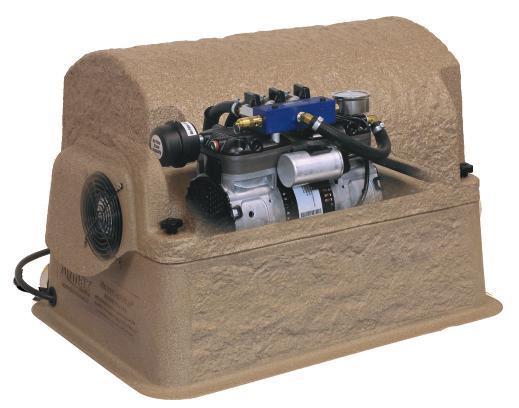
3 1. System Components ENGLISH Airmax Composite Cabinet 2 1. Enhanced Cooling System tunnels air flow evenly through the cabinet with a high flow cooling fan 2. Composite cabinet with removable top protects components while providing easy access 3. Elevated base protects against damaging flood water Pre-wired electrical box simplifies electrical connections for easy setup 3 5. Dual Air Filters High density cabinet intake pre-filter and compressor air filter maximize the life of the system 4 6. Cabinet Lock Kit protects your investment from unwanted guests 6 Cabinet Lock Kit Cabinet Size: 23 L x 17 W x 15 H Cabinet Size: 27 L x 24 W x H (PS80 Only) 2 SilentAir RP Series Rocking Piston Compressor SilentAir with SmartStart Technology 5 8 SmartStart Technology: Protects compressor during pressurized restarts following power supply interruptions. 1. High efficiency, continuous-duty rocking piston compressor 2. Air Filter maximizes the life of the compressor 3. Rubber compressor mounts reduce noise and vibration for silent operation 4. Airflow manifold simplifies airflow management to individual diffusers 5. Heat-resistant 3 8 flex-tube protects against high temperatures of the compressor and braided hose sleeve protects against wear 6. Pressure gauge helps monitor system performance 7. Pressure relief valve safeguards from back pressure 8. Airline quick disconnects for easy system removal and storage Note: These systems are designed for ponds up to 21 deep. Operating in depths greater than 21 will require a Deep Water Kit. See section 6 for kits. ProAir 4 Weighted Diffuser EasySet AIRLINE 1 1. PTFE non-stick 6 membrane diffuser sticks provides the synergy of air stones while being virtually maintenance-free 2. Check valve prevents back pressure to compressor Weighted design keeps diffuser submerged while maintaining an upright position during installation Diffuser Size: 19 L x 19 W x 5 H Self-Weighted Airline: 3/8 100 Roll (#510118), 5/8 100 Roll (#510119): Lead-free weighted airline is made of durable PVC composite. Fish hook resistant and kink-free. Use from pond s edge to diffuser. Direct Burial Airline: 5/8 100 Roll (#510120) Flexible, yet kink-free. Bury from cabinet and compressor to pond s edge when placing the cabinet and compressor away from the pond. * Depending on the type of installation, additional connector kits may be required. See section 6 for connector kits. 3
 10.")


. See Page 9.")

4 2. System Installation ENGLISH Tech Specs: HP Running Amps Volts Max CFM Power Cord *Ponds greater than 21 will require a Deep Water Kit Max Pond Size Max Depth* PS10 1/4 1.6 or V or 230V 2.3 6' 1 Acre 50' 1 PS20 1/2 4.1 or V or 230V 4.7 6' 2 Acres 50' 2 PS30 1/2 4.1 or V or 230V 4.7 6' 3 Acres 50' 3 PS40 3/4 5.3 or V or 230V 5.8 6' 4 Acres 50' 4 PS80 3/4 (x2) 10.6 or V or 230V ' 8 Acres 50' 8 # Diffusers Tools Required: Placement Rope Utility razor knife See Video Instructions of the Level Boat/Raft/Swimsuit Small stone or gravel Shovel Airmax Aeration System installation online at Rake Flathead screwdriver airmaxeco.com/pondseriesaeration Permanent Marker Coast Guard-approved life jacket STEP ONE: Select a Location for the Aeration Cabinet Locate cabinet on a solid surface with adequate strength for the weight of the unit. Locate cabinet away from irrigation sprinklers. Cabinet must always remain above the high water mark. Ý Attention: For airline that runs longer than 100, connector kits are required (sold separately). See Page 9. Option A Option B Option B with Remote Manifold Pond s Edge Away from Pond s Edge If a power source is available near the pond s If a power source is not available near the pond s shore, locate the cabinet at the pond s edge for shore or you would prefer to install the cabinet quicker installation. in another location, install Direct Burial Airline(s) (sold separately) from the cabinet s location to the pond s edge. STEP TWO: Prepare the Ground Surface and Place the Cabinet Use a single airline from cabinet to shoreline with valves at pond s edge. Learn about installing an optional Remote Manifold Kit online at airmaxeco.com/remotemanifold 1. Place the cabinet on the ground in the selected location and mark an area 6 wider than the base of the cabinet on all sides. 2. Move the cabinet and remove the sod from the area, filling in with small stone or gravel. This allows for a firm base for the cabinet and for drainage. Open the aeration cabinet by unscrewing the 4 lobed thumb screws. Gently lift the cabinet lid and lay on its side next to the base. 3. Place the cabinet onto the stone base and use your level to make sure the cabinet is sitting secure and level. 4

5 2. System Installation - Continued ENGLISH STEP THREE: Excavate Trench and Place Airline(s) 1. Using your shovel, dig a trench from the cabinet to the pond s edge. This trench should be a minimum depth of 8 to protect the airline. We recommend having utility lines marked before you begin digging. STEP FOUR: Connect Airline(s) to the Compressor Manifold STEP FIVE: Partially Backfill Airline Trench 2. Place airline into the trench from the aeration cabinet to the pond s edge. Option A: Use EasySet weighted airline. There must be a separate run of airline for each diffuser that will be installed. Leave remaining airline coiled at the pond s edge. Option B: Use Direct Burial airline. There must be a separate run of airline for each diffuser that will be installed. Join multiple sections of direct burial airline using 5/8 connector kits. First, slide two hose clamps onto one section of airline. Next insert the 5/8 insert adaptor half way into one section of airline and then insert into next the section of airline. Using a flathead screw driver, secure one of the hose clamps onto each half of the insert adaptor (see image on the left). Option B with Remote Manifold: Use 1 Direct Burial Airline or PVC Pipe. Only 1 run of airline is required from the cabinet location to the pond s edge. See Remote Manifold Kit Manual or watch the installation video at airmaxeco.com/remotemanifold for more information. Attention: For ponds deeper than 21 deep, a Deep Water Kit (Sold Separately) must be installed before continuing with installation. Option A & B: (this step is not required if a Deep Water Kit is installed) Slide a hose clamp onto the airline and insert a 3/4 MPT to 3/8 (or 5/8 ) Insert Reducer to into the airline, securing with a hose clamp. Next, hand tighten to one of the quick disconnect flex tubes coming from the compressor manifold. Repeat for each diffuser line. Option B with Remote Manifold: Refer to the Remote Manifold Kit Manual or watch the installation video at airmaxeco.com/remotemanifold for more information. Backfill the airline trench in a few areas to temporarily keep the airline in place until installation is complete. 5


6 2. System Installation - Continued ENGLISH STEP SIX: Connect Weighted Airline for Diffusers Unroll the EasySet weighted airline and remove any kinks or twists. Join enough sections of weighted airline, using 3/8 or 5/8 connector kits, so that the airline can rest on the bottom of the pond, from the pond s edge out to the planned location for each diffuser. For option B installations, connect the weighted airline to the direct burial airline or Remote Manifold Kit at the pond s edge. Note: Diffusers should be placed equally apart or in areas of low water movement for optimum performance. If you need help choosing the correct location for your diffusers, please contact Airmax or your local dealer. STEP SEVEN: Connect ProAir Diffusers See the ProAir Diffuser Manual for assembling and connecting the diffusers. STEP EIGHT: Start the Aeration System PS10 Systems: Plug the compressor and cooling fan into the power control outlet inside of the cabinet. Plug the power control outlet into a GFCI power outlet. PS20, PS30, PS40, PS80 Systems: Plug the compressor into the power control outlet inside of the cabinet. Ensure the power switch is in the ON position. Plug the power control outlet into a GFCI power outlet. STEP NINE: Install the ProAir Diffusers Installing Diffusers from a Boat/Raft: Have one person on shore guiding the airline as a second person uses a boat or raft, extend the airline out to the area of the pond that the diffuser will be located. Gently release the diffuser into the water. Repeat until all diffusers are in position. Installing Diffusers from Shore: For smaller ponds you may choose to install the diffusers from shore. Have one person guide the airline while another walks around the pond with the diffuser. Then thread nylon rope through the diffuser manifold. Use the nylon rope and airline to gently guide the diffuser into place. Once set, release one side of the nylon rope and pull to shore. Repeat until all diffusers are in position. 6
7 2. System Installation - Continued ENGLISH STEP TEN: Adjust Airflow Bubbles should be noticeable on the pond s surface from the diffuser locations. When more than one diffuser is installed, adjust the airflow valves on the compressor manifold (For Option B with Remote Manifold, do this step at the remote manifold). Once an adjustment is made you may need to wait several minutes to see the results at the diffuser location(s). Note: Deeper placement of diffusers and longer runs of airline will require more flow. STEP ELEVEN: Mark Pressure Gauge Using a permanent marker, mark the current pressure gauge reading. During regular maintenance if the reading is above or below this mark, it may indicate that the system requires maintenance. STEP TWELVE: Secure Cabinet & Prepare for Start-Up Secure the aeration cabinet lid with the 4 lobed screws. You can also secure the cabinet to prevent unwanted guests with the included Cabinet Lock Kit. Simply replace 2 lobed screws with 2 hex screws and use the hex tool to secure into place. Complete backfill on airline trenches and level with a rake. Complete installation by reviewing and following the Initial Start-Up Procedure in Section Initial Start-Up & Seasonal Operation The circulation of poor quality, low oxygen, deep water to the pond s surface can introduce harmful gases and by-products into the previously healthy upper regions of the water column. These by-products can make the upper regions unfit for aquatic life and could result in fish-kill. Initial Start-Up Procedure To Prevent Fish-Kill: Follow this procedure anytime system has been shut-off for an extended period of time. Day 1: Run system for 30 minutes; turn system off for remainder of day. Day 2: Run system for 1 hour; turn system off for remainder of day. Day 3: Run system for 2 hours; turn system off for remainder of day. Day 4: Run system for 4 hours; turn system off for remainder of day. Day 5: Run system for 8 hours; turn system off for remainder of day. Day 6: Run system for 16 hours; turn system off for remainder of day. Day 7: Begin running system 24 hours/day, 7 days/week. Summer Operation To reduce the risk of fish kills in hot summer months and for optimum aeration benefits, Airmax Aeration Systems should run continuously throughout the summer. To enhance pond health, reduce mucky bottoms and enhance pond s aesthetic appeal, try Pond Logic products: Ma MuckAway Pc PondClear Eb EcoBoost Tw Bk Nb Ab Pond Dye Winter Operation Owner assumes all responsibility for operating Airmax Aeration System during winter months. Operating in freezing conditions on an ice-covered pond will cause large open water areas at diffuser sites. Ice thickness around open areas will be much thinner than the surrounding areas. Airmax strongly recommends that Danger - Thin Ice be posted at frequent intervals around pond. If you choose to turn your system off for the winter, do the following: Unplug your aeration system. Disconnect compressor flex-tube(s) from airline(s). Cover airline ends with the included winterization caps to prevent debris from entering airline. Move cabinet and compressor inside to keep dry. If operating during the winter season, condensation could cause airlines to freeze. If so: Use 1 cup isopropyl alcohol in the airline running out to each plate. Turn on compressor to push through line and free any ice blockage. 7

8 4. Maintenance** Airmax Aeration Systems are designed for low-maintenance and require minimal scheduled maintenance. Cabinet inlets and outlets should be kept free of debris and weed growth allowing normal ventilation. Always unplug system before performing any maintenance or troubleshooting. Always unplug system and refer servicing to a qualified electrician when: cord is damaged or frayed, compressor, power control, compressor fan, or other electrical components are producing unusual noises or odors. Always use parts that are supplied or approved by Airmax, Inc. Use of other parts may result in poor performance and could create a hazardous situation. **Local environmental conditions may require more frequent maintenance. WARNING: Compressors are equipped with a thermal overload switch. If temperature becomes high enough to trip the overload, the compressor will shut down. It will then automatically start up when temperature decreases as long as power is applied. 5. Troubleshooting ENGLISH EVERY 3-6 MONTHS Air Filter: Clean/replace air filter. Cooling Fan: Check to ensure cooling fan is operating. Hot air should be pulled from the cabinet, not blowing in. Pressure Gauge: Mark pressure gauge upon initial start up. Check to verify pressure has not significantly risen above or dropped below initial reading. Normal operation will range between 5-10psi. Pressure Relief Valve: Check to ensure air is not escaping from valve and replace if needed. EVERY MONTHS Maintenance Kit: It is recommended to install a maintenance kit every months to ensure optimum performance. EVERY MONTHS Membrane Sticks: We recommend inspecting and/or cleaning the membrane diffuser sticks every months, or anytime the pressure gauge reading is significantly higher than normal or there is a reduction in bubbles from the diffuser. To clean, use Airmax Fountain & Aeration Cleaner (#530298) and a soft cloth. Watch the Maintenance Kit How-To Video at airmaxeco.com/pondseriesaeration IF COMPRESSOR IS NOT OPERATING: ISSUE CHECK LIKELY CAUSE CORRECTION Option 1: Check for power. Compressor and fan are not receiving power. Open cabinet and ensure the compressor and fan are plugged into the power outlet. For PS20-PS80 systems, also ensure the power switch is on. Cabinet fan is not running. Option 2: GFCI circuit tripped. Option 3: GFCI circuit not tripped. Damage to electrical cord or low voltage from power supply. GFCI malfunction. Contact Airmax or local dealer for electrical troubleshooting assistance. Option 1: Check compressor for power. Compressor is not receiving power. Open cabinet and ensure the compressor is plugged into the power outlet. Cabinet fan is running. Option 2: Check compressor capacitor wiring for frays or poor connections. Option 3: No capacitor wiring issues can be seen. Wiring loosened or was damaged during shipment or maintenance. Bad capacitor. Contact Airmax or local dealer for repair/replacement. Option 4: Capacitor has been replaced. Compressor is bad. IF COMPRESSOR IS OPERATING: ISSUE CHECK LIKELY CAUSE CORRECTION No bubbles at any diffusers. Option 1: No air leaks are audible in cabinet. Compressor running louder and possible excessive vibration. Option 2: Compressor operating normally or making unusual noises. Exhibits reduced pressure and/or air flow. Compressor air filter is dirty/clogged. Compressor needs maintenance kit and possibly new air filter. Clean or replace air filter. NEVER re-install wet filter. Contact Airmax or local dealer with specifications for maintenance kit. Clean or replace air filter. NEVER re-install wet filter. Option 1: Check for leaks at all connections in line and in cabinet. If none are audible, carefully spray SMALL amount of soapy water onto connections and look for bubbles. Vibration loosened connection or cracked fitting. Tighten loose connection or replace cracked fitting as necessary. No bubbles at some diffuser plates. Option 2: Are all flow control valves in compressor wide open? Improper balancing of diffusers. Adjust air flow valves on manifold in cabinet until all diffusers operate properly. See Section 2. System Installation for more information. Option 3: Valves in cabinet are properly balanced and no leaks are evident. Compressor beginning to lose compression and needs maintenance kit. Contact Airmax or local dealer with compressor specifications for maintenance kit. Large rolling bubbles instead of fine bubbles at surface above one or more diffuser plates. Inspect each diffuser plate for malfunction. Diffuser membrane damaged, diffuser plate fitting broken or diffuser plate is flipped over. Contact Airmax or local dealer for repair/replacement. Air coming out of pressure relief valve. Option 1: High pressure reading on gauge. Inspect diffuser plates and tubing for clogging. Option 2: Low pressure reading on gauge. Diffuser plates not clogged. Diffuser maintenance needed. Bad pressure relief valve. Remove any overgrowth around diffuser membrane surface. See Section 4. Maintenance for more information. Contact Airmax or local dealer for repair/replacement. Compressor stops working for periods of time, then restarts. Inspect cooling fan for proper function. Compressor over-heating due to bad cooling fan. Contact Airmax or local dealer for fan replacement. If possible, leave top of cabinet open for cooling. Otherwise, unplug system until fan is replaced. 8 Compressor shakes erratically and is making loud noises. Option 1: Check for low voltage while compressor is running. Gauge of supply wires to circuit possibly undersized or cabinet is plugged into extension cord. If gauge of circuit wiring is incorrect, have electrician replace. NEVER use extension cord to operate system for continual use. Option 2: Check for clogged air filter. Air filter in need of replacement. Clean or replace air filter. NEVER re-install wet filter.
 1/4 HP Single Piston Compressor, 115V #510504 RP25 (87R) 1/4 HP Single Piston Compressor, 230V #510501 RP50 (87R) 1/2 HP Dual Piston")
 1/4 HP Maintenance Kit #510511 RP50 (87R) 1/2 HP Maintenance Kit #510512 RP75 (72R) 3/4 HP Maintenance Kit 2. #490239 Pressure Relief Valve 3. #490272 Pressure Gauge 4.")
 7. #490194 3 8 Flex-Tube 8. Air Filter #510150 Air Filter, Complete #510151 Air Filter Media Only ProAir 4 Replacement Parts 9.")
9 6. Replacement Parts / Accessories ENGLISH Optional Optional Remote Manifold Kit (Airmax 4-Port Manifold Kit Shown) Cabinet & Compressor Replacement Parts 1. RP Series SilentAir High Efficiency Compressor # RP25 (87R) 1/4 HP Single Piston Compressor, 115V # RP25 (87R) 1/4 HP Single Piston Compressor, 230V # RP50 (87R) 1/2 HP Dual Piston Compressor, 115V # RP50 (87R) 1/2 HP Dual Piston Compressor, 230V # RP75 (72R) 3/4 HP Dual Piston Compressor, 115V # RP75 (72R) 3/4 HP Dual Piston Compressor, 230V # RP25 (87R) 1/4 HP Maintenance Kit # RP50 (87R) 1/2 HP Maintenance Kit # RP75 (72R) 3/4 HP Maintenance Kit 2. # Pressure Relief Valve 3. # Pressure Gauge 4. Airflow Manifold Assembly # PS10 # PS20 # PS30 # PS40 # PS80 5. Cooling Fan # Cooling Fan for 115V Systems # Cooling Fan for 230V Systems 6. # Air Intake Pre-Filter # Air Intake Pre-Filter (PS80 Only) 7. # Flex-Tube 8. Air Filter # Air Filter, Complete # Air Filter Media Only ProAir 4 Replacement Parts 9. # Diffuser Manifold 10. # Diffuser Sled 11. # PTFE 6 Membrane Stick 12. # Check Valve Optional Remote Manifold Kits *# Marine Stainless Hose Clamp *# ½ to ¾ Insert Reducer Adapter *# to ¾ Insert Reducer Adapter *Not shown in Diagram EasySet Airline # Weighted Airline, 100 Roll # Weighted Airline, 100 Roll # Direct Burial Airline, 100 Roll Connector Kits 13. # Airmax PS20 2-Port Remote Manifold Kit # Airmax PS30 3-Port Remote Manifold Kit # Airmax PS40 4-Port Remote Manifold Kit 3/8 Connector Kit # /8 to 5/8 Connector Kit # /8 Connector Kit # Optional Deep Water Kit For use on PondSeries Systems when water is greater than 21' deep. # PS10 # PS20 # PS30 # PS40 # PS80 THANK YOU FOR CHOOSING Security Kits # Security Stake Kit (Optional) # Cabinet Lock Kit Cabinet Lock Kit Security Stake Kit Cleaning Water Naturally 9
10 1. Composants du Système FRANÇAIS 4 Airmax Cabinet Composite Système de refroidissement amélioré tunnels flux d air uniformément à travers le boîtier avec un ventilateur de refroidissement à haut débit 2. Armoire composite avec toit amovible protège les composants tout en offrant un accès facile 3. Base surélevée protège contre les eaux de crue dommageable 4. Boîte électrique pré-câblé simplifie les connexions électriques pour une installation facile 5. Filtres double air - aspiration de l armoire haute densité pré-filtre et le filtre à air du compresseur maximisent la durée de vie du système 6. Kit de verrouillage Cabinet protège votre investissement de les hôtes indésirables Taille du Cabinet: 23 L x 17 W x 15 H Taille du Cabinet: 27 L x 24 W x H (PS80 Seulement) 6 Kit de verrouillage Cabinet SilentAir Série RP Rocking compresseur à piston SilentAir avec SmartStart Technologie SmartStart Technologie: Protège compresseur pendant le redémarrage sous pression après les interruptions d alimentation. 1. Rendement élevé, en service continu à bascule compresseur à piston 2. Filtre à air maximise la durée de vie du compresseur 3. Caoutchouc compresseur montures réduire le bruit et les vibrations pour un fonctionnement silencieux 4. Airflow collecteur simplifie la gestion des flux d air vers les diffuseurs individuels 5. Résistant à la chaleur 3/8 à tube flexible protège contre les températures élevées du manchon de compression et le tuyau tressé pour protéger contre l usure 6. Manomètre aide les performances du système de contrôle 7. Décompression garanties de soupape de pression 8. Déconnexion rapide avion pour le retrait facile du système et de stockage Remarque: Ces systèmes sont conçus pour les bassins jusqu à 21 de profondeur. Opérant dans des profondeurs supérieures à 21 exigera un kit de l eau profonde. Voir la section 6 pour les kits. ProAir 4 Diffuseur Pondéré EasySet Ligne Aérienne 1 1. PTFE antiadhésif 6 bâtons diffuseurs à membrane fournit la synergie des pierres de l air tout en étant pratiquement exempt d entretien Clapet anti-retour empêche la contre-pression à compresseur 3. Conception pondéré maintient diffuseur immergé tout en maintenant une position verticale lors de l installation Taille du diffuseur: 19 L x 19 W x 5 H Airline auto-pondéré: 3/8 100 Rouleau (#510118), 5/8 100 Rouleau (#510119): compagnie aérienne pondéré plomb est faite de biens PVC composite. Hameçon résistant et kink-libre. Utilisez de au bord de l étang de diffuseur. Airline Enfouissement direct: 5/8 100 Rouleau (#510120) Flexible, encore kink-libre. Enterrez de cabinet et compresseur au bord de l étang lorsque vous placez l armoire et le compresseur loin du pond. * Selon le type de installation, supplémentaire kits de connexion peuvent être equis. Voir la section 6 pour kits de connecteurs.
11 2. Installation du système FRANÇAIS Spécifications techniques: HP Exécution Amps Volts Max CFM Cordon d alimentation Max Étang Taille Profondeur max* # Diffuseurs PS10 1/4 1.6 or V or 230V 2.3 6' 1 Acre 50' 1 PS20 1/2 4.1 or V or 230V 4.7 6' 2 Acres 50' 2 PS30 1/2 4.1 or V or 230V 4.7 6' 3 Acres 50' 3 PS40 3/4 5.3 or V or 230V 5.8 6' 4 Acres 50' 4 PS80 3/4 (x2) 10.6 or V or 230V ' 8 Acres 50' 8 Outils nécessaires: Nylon Rope Niveau Petite pierre ou de gravier Râteau Marqueur permanent Couteau tout usage Bateau / Raft Pelle Tournevis à tête plate Gilet de sauvetage de la Garde côtière approuvée ÉTAPE 2: Préparer la surface du sol et placez l armoire * Étangs supérieure à 21 exigera un kit de conversion Deep Water Voir vidéo Instructions de la Installation Airmax Système d Aération en ligne à airmaxeco.com/pondseriesaeration ÉTAPE 1: Sélectionnez un emplacement pour le cabinet d aération Placer l armoire sur une surface solide avec une force suffisante pour le poids de l unité. Repérez armoire loin de gicleurs d irrigation. Cabinet doit toujours rester au-dessus de la marque des hautes eaux. Ý Attention: Pour la compagnie aérienne qui fonctionne plus de 100, kits de connexion sont nécessaires (vendus séparément). Voir la page 9. Edge étang Option A Si une source d alimentation est disponible à proximité de la rive de l étang, localiser l armoire au bord de l étang pour une installation plus rapide. Loin de Edge étang Option B Option B avec collecteur à distance Utilisez une seule compagnie aérienne du cabinet au littoral avec des vannes au bord de l étang. En savoir plus sur l installation d un kit de collecteur à distance en option en ligne à airmaxeco.com/remotemanifold Si une source d alimentation ne sont pas disponibles à proximité de la rive de l étang ou vous préférez installer l armoire dans un autre emplacement, installez Airline(s) Burial Direct (vendu séparément) à partir de l emplacement de l armoire au bord de l étang. 1. Placez l armoire sur le sol à l emplacement choisi et marquer une zone 6 plus large que la base de l armoire sur tous les côtés. 2. Déplacez l armoire et retirez le gazon de la zone, en remplissant avec une petite pierre ou de gravier. Cela permet d une base solide pour le cabinet et pour le drainage. Ouvrez l armoire d aération en dévissant les 4 vis de pouce lobées. Soulevez délicatement le couvercle de l armoire et de jeter sur le côté à côté de la base. 3. Placez l armoire sur la base de pierre et utilisez votre niveau pour vous assurer que le cabinet est assis sécurisé et de niveau. 11


12 2. Installation du système - A continué FRANÇAIS ÉTAPE 3: Creuser tranchée et placer compagnie aérienne(s) 1. Utilisation de votre pelle, creuser une tranchée de l armoire au bord de l étang. Cette tranchée doit être une profondeur minimale de 8 pour protéger la compagnie aérienne. Nous recommandons d avoir des lignes électriques marquées avant de commencer à creuser. 2. Placez aérienne dans la tranchée de l armoire d aération au bord de l étang. Option A: Utilisez EasySet compagnie aérienne pondéré. Il doit y avoir une course séparée de la compagnie aérienne pour chaque diffuseur qui sera installé. Laissez restante aérienne enroulée au bord de l étang. Option B: Utilisez aérienne Burial Direct. Il doit y avoir une course séparée de la compagnie aérienne pour chaque diffuseur qui sera installé. Joignez-vous à plusieurs sections de transport aérien enfouissement direct en utilisant 5/8 kits de connecteurs. Tout d abord, faites glisser deux colliers de serrage sur une section de la compagnie aérienne. Ensuite, insérer le 5/8 adaptateur insert à mi-chemin dans une section de la compagnie aérienne, puis insérer dans la prochaine section de la compagnie aérienne. L utilisation d un tournevis à tête plate, fixez l un des colliers de serrage sur chaque moitié de l adaptateur d insertion (voir image à gauche). Option B avec Manifold à distance: Utilisez 1 Airline Burial Direct ou PVC Pipe. Seulement 1 terme de la compagnie aérienne est nécessaire à partir de l emplacement de l armoire au bord de l étang. Voir à distance Manifold Manuel Kit ou regarder la vidéo d installation au airmaxeco.com/remotemanifold pour plus d informations. ÉTAPE 4: Connectez avion au collecteur du compresseur Attention: Pour les étangs plus profonds que 21 de profondeur, un kit de Deep Water (vendu séparément) doit être installé avant de poursuivre l installation. Option A & B: (Cette étape est pas nécessaire si un kit de Deep Water est installé) Faites glisser un collier de serrage sur la compagnie aérienne et insérer un MPT à 3/8 (ou 5/8 3/4) Insérer Réducteur à dans la compagnie aérienne, fixant avec un collier de serrage. Ensuite, serrez à la main à l un des tubes flexibles débranchement rapide provenant du collecteur du compresseur. Répétez l opération pour chaque ligne de diffuseur. Option B avec Manifold à distance: Voir à distance Manifold Manuel Kit ou regarder la vidéo d installation au airmaxeco.com/remotemanifold pour plus d informations. ÉTAPE 5: Partiellement remblai aérienne tranchée Remblayer la tranchée du transport aérien dans quelques zones pour maintenir temporairement la compagnie aérienne en place jusqu à ce que l installation est terminée. 12


13 2. Installation du système - A continué FRANÇAIS ÉTAPE 6: Airline pondérée Coonect pour Diffuseurs Déroulez la compagnie aérienne pondérée EasySet et supprimer tous les plis ou torsions. Joignez-vous suffisamment de sections aérienne pondérée, en utilisant 3/8 ou 5/8 kits de connecteurs, de sorte que la compagnie aérienne peut reposer sur le fond de l étang, du bord de l étang à l emplacement prévu pour chaque diffuseur. Pour les installations l option B, connectez la compagnie aérienne pondérée à la compagnie aérienne ou l enfouissement direct Kit distance Manifold au bord de l étang. Note: Diffuseurs doivent être placés aussi en dehors ou dans des zones de circulation d eau faible pour des performances optimales. Si vous avez besoin d aide pour choisir le bon emplacement pour vos diffuseurs, s il vous plaît contacter Airmax ou votre revendeur local. ÉTAPE 7: Connectez diffuseurs ProAir Voir le manuel ProAir Diffuseur pour le montage et le raccordement des diffuseurs. ÉTAPE 8: Démarrez le système d aération PS10 Systèmes: Branchez le compresseur et le ventilateur de refroidissement dans la prise de contrôle de puissance à l intérieur de l armoire. Branchez la prise de contrôle d alimentation dans une prise de courant GFCI. PS20, PS30, PS40, PS80 Systèmes: Branchez le compresseur dans la prise de courant située à l intérieur de l armoire. Assurez-vous que l interrupteur d alimentation est en position «ON». Branchez la prise de courant dans une prise de courant GFCI. ÉTAPE 9: Installez les diffuseurs ProAir Installation Diffuseurs à partir d un bateau / Raft: Demandez à une personne sur le rivage de guidage de la compagnie aérienne en tant que deuxième personne utilise un bateau ou d un radeau, prolonger la ligne aérienne vers la zone de l étang que le diffuseur sera situé. Relâchez doucement le diffuseur dans l eau. Répétez jusqu à ce que tous les diffuseurs sont en position. Installation Diffuseurs de Shore: Pour les petits étangs, vous pouvez choisir d installer les diffuseurs de la rive. Demandez à une personne guider la compagnie aérienne tandis qu une autre marche autour de l étang avec le diffuseur. Puis enfiler une corde de nylon par la tubulure de diffuseur. Utilisez la corde de nylon et la compagnie aérienne pour guider doucement le diffuseur en place. Une fois réglée, relâchez un côté de la corde de nylon et tirez sur le rivage. Répétez jusqu à ce que tous les diffuseurs sont en position. 13


14 2. Installation du système - A continué ÉTAPE 10: Réglez Airflow FRANÇAIS Bubbles devraient être visibles à la surface de l étang à partir des emplacements de diffuseur. Lorsque plus d un diffuseur est installé, régler les soupapes d écoulement d air sur le compresseur collecteur (Pour l option B avec Manifold à distance, cette étape au niveau du collecteur à distance). Une fois qu un réglage est effectué, vous devrez peut-être attendre plusieurs minutes pour voir les résultats à l emplacement(s) de diffuseur. Remarque: Le placement Deeper de diffuseurs et de plus longues séries de transport aérien, il faudra plus de débit. ÉTAPE 11: Mark Manomètre L utilisation d un marqueur permanent, marquer la lecture de la jauge de pression actuelle. Au cours de l entretien régulier si la lecture est au-dessus ou au-dessous de cette marque, il peut indiquer que le système nécessite un entretien. ÉTAPE 12: Fixer l armoire et se préparer à Start-up Fixer le couvercle d aération de l armoire avec les 4 vis lobées. Vous pouvez également sécuriser l armoire pour empêcher les hôtes indésirables avec le Kit de verrouillage Cabinet inclus. Il suffit de remplacer les 2 vis lobées avec 2 vis hexagonales et utiliser l outil hexagonal pour fixer en place. remblayage complet sur les tranchées aériennes et le niveau avec un râteau. Installation complète en examinant et en suivant la procédure de démarrage initiale à la section Mise en service et exploitation saisonnière La circulation de mauvaise qualité, faible teneur en oxygène, en eau profonde à la surface de l étang peut introduire gaz nocifs et sous-produits dans les régions supérieures auparavant en bonne santé de la colonne d eau. Ces sous-produits peuvent faire les régions supérieures impropres à la vie aquatique et pourrait entraîner dans les poissons-kill. Procédure de démarrage initial pour empêcher Fish-Kill: Suivez ce système à tout moment de la procédure a été d arrêt pour une période de temps prolongée. Jour 1: Fonctionner le système pendant 30 minutes; Éteignez le système pour le reste de la journée. Jour 2: Fonctionner le système pendant 1 heure; Éteignez le système pour le reste de la journée. Jour 3: Fonctionner le système pendant deux heures; Éteignez le système pour le reste de la journée. Jour 4: Fonctionner le système pendant quatre heures; Éteignez le système pour le reste de la journée. Jour 5: Fonctionner le système pendant 8 heures; Éteignez le système pour le reste de la journée. Jour 6: Fonctionner le système pendant 16 heures; Éteignez le système pour le reste de la journée. Jour 7: Commencez système fonctionnant 24 heures / jour, 7 jours / semaine. Opération Été Pour réduire le risque de mortalité massive de poissons dans les mois chauds d été et pour les prestations d aération optimales, Airmax Systèmes d aération doit fonctionner en continu pendant tout l été. Pour améliorer la santé de l étang, de réduire les fonds boueux et d améliorer l aspect esthétique de l étang, essayer les produits Pond Logic : Ma MuckAway Pc PondClear Eb EcoBoost Tw Bk Nb Ab Pond Dye Opération Hiver Propriétaire assume toute la responsabilité de l exploitation Airmax système d aération pendant les mois d hiver. Fonctionnant dans des conditions de congélation sur un étang couvert de glace provoquera de grands espaces ouverts de l eau sur les sites de diffusion. épaisseur de la glace autour des zones ouvertes sera beaucoup plus mince que les zones environnantes. Airmax recommande fortement que Danger - Thin Ice sera affiché à intervalles réguliers autour de l étang. Si vous choisissez de mettre votre système pour l hiver, procédez comme suit: Débranchez votre système d aération. Débranchez le compresseur de tube flexible(s) d une compagnie(s). Couverture aérienne se termine avec la hivernage inclus Caches pour empêcher les débris d entrer aérienne. Déplacer cabinet et compresseur à l intérieur pour garder au sec. En cas de fonctionnement au cours de la saison d hiver, la condensation pourrait causer aux compagnies aériennes de geler. Si oui: Utilisez une tasse d alcool isopropylique dans la compagnie aérienne manquer à chaque plaque. Allumez compresseur pour faire passer la ligne gratuits et tout blocage de glace.
15 5. Entretien ** Airmax Systèmes d aération sont conçus pour peu d entretien et nécessite un minimum maintenance planifiée. Entrées et sorties du Cabinet doivent être libres de débris et de croissance des mauvaises herbes permettant une ventilation normale. Toujours débrancher le système avant d effectuer tout entretien ou dépannage. Toujours débrancher le système et faites appel à un électricien qualifié si: le cordon est endommagé ou usé, compresseur, commande de puissance, ventilateur de compresseur, ou d autres composants électriques produisent des bruits ou des odeurs inhabituelles. Toujours utiliser des pièces qui sont fournis ou approuvés par Airmax, Inc. L utilisation d autres pièces peut entraîner de mauvaises performances et pourrait créer une situation dangereuse. ** Les conditions environnementales locales peuvent exiger un entretien plus fréquent. AVERTISSEMENT: Les compresseurs sont équipés d un interrupteur de surcharge thermique. Si la température devient suffisamment élevée pour déclencher la surcharge, le compresseur se arrête. Il commencera alors automatiquement lorsque la température diminue aussi longtemps que l alimentation est appliquée. 6. Dépannage FRANÇAIS TOUS LES 3-6 MOIS - Filtre à air: Nettoyer / remplacer le filtre à air. Ventilateur de refroidissement: Vérifier pour assurer le ventilateur de refroidissement fonctionne. L air chaud doit être tiré de l armoire, ne souffle pas dans. Manomètre: Mark jauge de pression sur le démarrage initial. Vérifiez de vérifier la pression n a pas augmenté de manière significative au-dessus ou chuté en dessous de la lecture initiale. Le fonctionnement normal se situera entre 5-10psi. Soupape de décharge: Vérifier pour assurer l air n échappe pas de la vanne et remplacer si nécessaire. TOUS LES MOIS - KIT D ENTRETIEN: Il est recommandé d installer un kit de maintenance tous les mois afin d assurer une performance optimale. CHAQUE MOIS BÂTONS MEMBRANAIRES: Nous recommandons l inspection et / ou le nettoyage des bâtons de diffuseur à membrane tous les mois, ou à tout moment de la lecture de la jauge de pression est nettement supérieure à la normale ou il y a une réduction des bulles du diffuseur. Pour nettoyer, utilisez Airmax Fountain & Aération Cleaner (#530298) et un chiffon doux. Regarder le kit de maintenance Comment à la vidéo à airmaxeco.com/pondseriesaeration SI LE COMPRESSEUR NE FONCTIONNE PAS: QUESTION VOIR CAUSE PROBABLE CORRECTION Option 1: Vérifier l alimentation. Le compresseur et le ventilateur ne reçoivent pas d alimentation. Ouvrez l armoire et assurez-vous que le compresseur et le ventilateur sont branchés sur la prise de courant. Pour les systèmes PS20-PS80, assurezvous également que l interrupteur d alimentation est allumé. Fan du Cabinet ne fonctionne pas. Option 2: Circuit GFCI déclenché. Option 3: Circuit GFCI ne se déclenche pas. Dommage pour le cordon électrique ou basse tension de l alimentation. GFCI malfunction. Contacter Airmax ou revendeur local pour obtenir électrique Assistance dépannage. Option 1: Vérifier la puissance du compresseur. Le compresseur ne reçoit pas de courant. Ouvrez l armoire et assurez-vous que le compresseur est branché sur la prise de courant. Fan du Cabinet est en marche. Option 2: Vérifiez le câblage compresseur condensateur pour s effiloche ou mauvaises connexions. Câblage desserré ou a été endommagé pendant le transport ou l entretien. Option 3: Pas de problèmes de câblage de condensateurs peuvent être vus. Bad condensateur. Contactez Airmax ou revendeur local pour la réparation / remplacement. Option 4: Condensateur a été remplacé. Compressor est mauvais. SI COMPRESSEUR EST EN MARCHE: QUESTION VOIR CAUSE PROBABLE CORRECTION Pas de bulles sur les diffuseurs. Option 1: Pas de fuites d'air sont audibles dans l'armoire. Compresseur en marche vibrations excessives fort et possible. Option 2: compresseur fonctionnant normalement ou faire des bruits inhabituels. Preuve de moins de pression et / ou le débit d'air. Filtre à air du compresseur est sale / bouché. Compresseur doit kit de maintenance de la membrane et peut-être nouveau filtre à air. Nettoyez ou remplacez le filtre à air. JAMAIS ré-installer un filtre humide. Contactez Airmax ou revendeur local avec les spécifications pour kit de maintenance. Nettoyez ou remplacez le filtre à air. JAMAIS ré-installer un filtre humide. Option 1: Vérifier s'il ya des fuites au niveau des raccords en ligne et en cabinet. Si aucun n'est audible, vaporiser soigneusement petite quantité d'eau savonneuse sur les connexions et de chercher les bulles. Vibration desserré connexion ou fissuré raccord. Serrer connexion lâche ou remplacer raccord fissuré si nécessaire. Pas de bulles à quelques plaques de diffuseur. Option 2: Est-ce que toutes les vannes de contrôle de débit de compresseur grande ouverte? Une mauvaise équilibre des diffuseurs. Régler les soupapes d écoulement d air du collecteur dans l armoire jusqu à ce que tous les diffuseurs fonctionner correctement. Voir la section 2. Installation d un système de plus d informations. Option 3: Vannes dans l armoire sont bien équilibré et aucune fuite sont évidents. Compresseur commence à perdre compression et doit kit de maintenance de la membrane. Contactez Airmax ou revendeur local avec les spécifications de compresseur pour kit de maintenance. Les grosses bulles de roulement au lieu de fines bulles à la surface ci-dessus une ou plusieurs plaques de diffusion. Inspectez chaque plaque de diffusion de dysfonctionnement. Membrane diffuseur endommagé, diffuseur plaque épousant la plaque cassée ou diffuseur est retournée. Contactez Airmax ou revendeur local avec les spécifications des compresseurs pour le kit de maintenance. Air qui sort de la soupape de décharge de pression. Option 1: lecture à haute pression sur le manomètre. Inspecter les plaques et tubes diffuseur pour le colmatage. Option 2: lecture de basse pression sur le manomètre. Plaques de diffusion non obstrués. Diffuseur entretien nécessaire. Illicite soupape de décharge de pression. Retirez toute prolifération autour de la surface de la membrane diffuseur. Voir la section 4. Maintenance pour plus d informations. Contactez Airmax ou revendeur local pour la réparation / remplacement. Le compresseur s arrête de travailler pour des périodes de temps, puis redémarre. Inspectez le ventilateur de refroidissement pour le bon fonctionnement. Compresseur surchauffe due à une mauvaise ventilateur de refroidissement. Contactez Airmax ou revendeur local pour le remplacement du ventilateur. Si possible, laissez le haut du coffret ouvert pour le refroidissement. Sinon, débranchez le système jusqu à ce fan est remplacé. Compresseur secoue erratique et fait des bruits forts. Option 1: Vérifier la faible tension alors que le compresseur est en marche. Option 2: Vérifiez si le filtre à air obstrué. Jauge de fils d alimentation au circuit éventuellement sous-dimensionné ou un meuble est branché sur une rallonge. Filtre à air dans le besoin de remplacement. Si l'indicateur de câblage du circuit est incorrecte, avoir replace électricien. NE JAMAIS utiliser de rallonge pour fonctionner le système pour une utilisation continue. Nettoyez ou remplacez le filtre à air. JAMAIS ré-installer un filtre humide. 15

 1/2 HP Double Compresseur à Piston, 230V #510502 RP75 (72R) 3/4 HP Double Compresseur à Piston, 115V #510506 RP75 (72R) 3/4 HP Double Compresseur")

16 6. Pièces de Rechange / Accessoires 4 9 FRANÇAIS Optionnel Kit de collecteur à distance en option (Airmax 4-Kit collecteur de port indiqué) Cabinet & Compresseur Pièces de Rechange 1. RP Séries SilentAir Compresseur haute efficacité # RP25 (87R) 1/4 HP Simple Compresseur à Piston, 115V # RP25 (87R) 1/4 HP Simple Compresseur à Piston, 230V # RP50 (87R) 1/2 HP Double Compresseur à Piston, 115V # RP50 (87R) 1/2 HP Double Compresseur à Piston, 230V # RP75 (72R) 3/4 HP Double Compresseur à Piston, 115V # RP75 (72R) 3/4 HP Double Compresseur à Piston, 230V # RP25 (87R) 1/4 HP Kit d entretien # RP50 (87R) 1/2 HP Kit d entretien # RP75 (72R) 3/4 HP Kit d entretien 2. # Clapet de décharge 3. # Manomètre 4. Assemblée du collecteur Airflow # PS10 # PS20 # PS30 # PS40 # PS80 5. Ventilateur # Ventilateur de 115V Systems # Ventilateur de 230V Systems 6. # Air Intake pré-filtre # Air Intake pré-filtre (PS80 seulement) 7. # Flex-Tube 8. Filtre à air # Filtre à air, complet # Filtre à air médias seulement ProAir 4 Pièces de Rechange 9. # Diffuser Manifold 10. # Diffuser Sled 11. # PTFE 6 Membrane Stick 12. # Check Valve *# Marine Stainless Hose Clamp *# ½ to ¾ Insert Reducer Adapter *# to ¾ Insert Reducer Adapter *Not shown in Diagram Kit de collecteur à distance en option EasySet Airline # Weighted Airline, 100 Roll # Weighted Airline, 100 Roll # Direct Burial Airline, 100 Roll Kit de Connexion 13. Kit de collecteur à distance en option # Airmax PS20 2-Port Kit collecteur à distance # Airmax PS30 3-Port Kit collecteur à distance # Airmax PS40 4-Port Kit collecteur à distance 3/8 Kit de connexion # /8 to 5/8 Kit de connexion # /8 Kit de connexion # Kit d eau profonde en option Pour une utilisation sur les systèmes PondSeries lorsque l eau est supérieure à 21 de profondeur. # PS10 # PS20 # PS30 # PS40 # PS80 MERCI D AVOIR CHOISI Kit de sécurités # Kit de sécurité Stake (Optionnel) # Kit de verrouillage Cabinet Kit de verrouillage Cabinet Kit de sécurité Stake Cleaning Water Naturally 16
17 NOTES Visit airmaxeco.com or call your local Airmax Dealer with questions or to order parts. 17
18 18
19 Airmax, Inc. Airmax Aeration Systems Limited Warranty Airmax, Inc. warrants to the original purchaser (the end user) of any Airmax Aeration System manufactured by Airmax, Inc. that any aeration system component which proves to be defective in materials or workmanship, as determined by the factory within the timeframe specified below from the shipping date, will be repaired or replaced at no charge with a new or remanufactured part, and returned freight prepaid. The end user shall assume all the responsibility and expense for removal, packaging, and freight to ship to Airmax, Inc. to determine the warranty claim and for all reinstallation expenses. Cabinet Lifetime Compressor 2 Years Airline & Diffusers 5 Years The warranty is void in cases where damage results from: improper installation, improper electrical connection, improper voltage, alteration, lightning, careless handling, misuse, abuse, disassembly of motor or failure to follow maintenance or operating instructions. Modification or repair by an unauthorized repair facility will void the warranty. Compressor seals, piston cups, cylinder sleeves, valves, air filters and diffuser membranes are considered wear parts and are not covered under warranty. In no case will Airmax, Inc. or its dealers accept responsibility for any costs incurred by the user during installation, removal, inspection, evaluation, repair, parts replacement, or for return freight. Nor will any liability be accepted for loss of use, loss of profits, loss of goodwill, for consequential damage, or for personal injuries to the purchaser or any person. In the event of problems believed to be covered under warranty, it will be necessary to notify the dealer who will try to help resolve the problem and who may contact the factory for additional assistance. If it is concluded that there may be a defect which may be covered under warranty, it will be necessary to get a Return Material Authorization (RMA) from the dealer before shipment. Freight collect shipments will not be accepted by the factory on warranties or repairs. The product or part(s) must be returned freight prepaid, to the factory, as directed, and in its original packaging or in a container which will prevent damage. Parts returned under warranty and damaged during shipping will not be covered under warranty for the shipping damage. If the factory evaluation of the returned goods concludes that the failure is due to defects in materials or workmanship, the part or parts in question will be replaced under warranty with new parts, remanufactured parts, or will be repaired; at the factory s option. The warranty period for all parts supplied under warranty will terminate at the end of the original product s warranty. All warranty shipments from the factory will be shipped freight prepaid. Warranty registration is HIGHLY recommended. No implied warranties of any kind are made by Airmax, Inc. for its products, and no other warranties, whether expressed or implied, including implied warranties of merchantability and fitness for a particular purpose, shall apply. Should an Airmax, Inc. product prove to be defective in materials or workmanship, the retail purchaser s sole remedy shall be repair or replacement of the product as expressly provided above. The manufacturer s warranty will begin from the dealer s original purchase date if the product is not registered. To register a product you are required to fill out the warranty form at airmaxeco.com/warranty. Warranty registration must be submitted directly to Airmax within 30 days of the end-users purchase date. When making warranty claims end-users may be required to supply their proof of purchase. 19

 4-AIRMAX")
20 Airmax Inc. Safe, Simple Solutions P.O. Box 38 Romeo, MI (866) 4-AIRMAX airmaxeco.com 044_13
Shallow Water Series SW20 & SW40
 Shallow Water Series SW20 & SW40 OWNER S MANUAL FOR: Shallow Water Series SW20 & SW40 MAX DEPTH 6 THANK YOU FOR CHOOSING The Airmax Aeration System You have purchased the most efficient and cost-effective
1. Configurez votre Stick Up Cam Wired dans l application Ring.
 Stick Up Cam Wired 1. Configurez votre Stick Up Cam Wired dans l application Ring. Téléchargez l application Ring. L application vous guide dans la configuration et l utilisation de votre Stick Up Cam
GUIDE D INSTALLATION PVC CELLULAIRE
 GUIDE D INSTALLATION PVC CELLULAIRE 7 5 3 4 1 2 6 8 NOTES IMPORTANTES Travailler toujours de gauche à droite, de bas en haut. Utiliser des vis en acier inoxidable #8 x 1.5 (3,8 cm) à tous les 16 /40,64
HOLA SAFETY RING PLAN
 FRENCH VERSION ON PAGE 3 HOLA SAFETY RING PLAN PRICE: $50.00 per person EFFECTIVE FEBRUARY 01, 2019 The Hola Safety Ring Plan allows you to cancel your trip with a refund up to 3 days before departure
kurt versen INSTALLATION INSTRUCTIONS-L342/4/6 SURFACE MOUNTED LED SQUARE CYLINDER
 INSTALLATION INSTRUCTIONS-L342/4/6 SURFACE MOUNTED LED SQUARE CYLINDER MODEL: 1100/1500/2100 LUMEN : L342/4/6 (WIDE, MEDIUM, & NARROW DISTRIBUTION) Fig. 1 MOUNTING YOKE J-BOX (BY OTHERS) HOUSING J-BOX
I We reserve the right to modify or attar Instructions. No modification or
 INSTALLATION INSTRUCTION VLFS3265 Floor Stand TV Mobile Cart For TV panels: 32"-65" Maximum load capacity: 100 lbs/ 45.5 kg AV shelf max load: 10 lbs/ 4.5 kg Video tray max load: 10 lbs/ 4.5 kg VESA: 100x100-600x400mm
, & Series Nested Hardware
 RECORD THIS INFORMATION FOR FUTURE REFERENCE BEFORE INSTALLING THE UNIT: Model Number Serial Number Date Purchased Place of Purchase USA SERVICE OFFICE Dometic Corp. 509 So. Poplar St. LaGrange, IN 46761
Roll Up 28. Ref A. DE Anleitung FR Notice ES Manual PT Instruções PL Instrukcja RU Руководство CS Návod
 Roll Up 28 WT Ref. 5122117A DE Anleitung FR Notice ES Manual PT Instruções PL Instrukcja RU Руководство CS Návod Copyright 2013 Somfy SAS. All rights reserved - V1-02/2013 1 Sommaire 1. Informations préalables
Thermographie, pourquoi l utiliser?
 Thermographie, pourquoi l utiliser? Manny Alsaid FLIR Systems Jacques Wagner MultiPro Plus = 3,600 Thermomètre IR Thermometre IR La zone de mesure Distance au cible Ce quoi l infrarouge? Voir la réalité
TCO REFERENCE: BBTS-500MR RGE CODIC:
 TCO MARQUE: BRANDT REFERENCE: BBTS-500MR RGE CODIC: 1370910 Model: BBTS 500MBK BBTS 500MS BBTS 500MR BBTS 500MBU AVERTISSEMENT Cet appareil est destiné à un usage domestique uniquement. Toute utilisation
P10SC01 900x2000 MANUEL D INSTALLATION / INSTALLATION MANUAL. 80"(2030mm) 78 3/4"(2000mm)
 78 3/4(2000mm)") Update: 000 P0SC0 900x000 ( /"~ ") (8.mm~8.mm) Le micro film protecteur formé lors de son application,fera perler l'eau sur le verre afin d'en faciliter l'entretien. II est recommandé de passer la raclette
Update: 000 P0SC0 900x000 ( /"~ ") (8.mm~8.mm) Le micro film protecteur formé lors de son application,fera perler l'eau sur le verre afin d'en faciliter l'entretien. II est recommandé de passer la raclette
INDOOR COOKING. Radiant Cooktop. Installation Manual
 INDOOR COOKING Radiant Cooktop KEC Installation Manual IF THE INFORMATION IN THIS MANUAL IS NOT FOLLOWED EXACTLY, A FIRE OR EXPLOSION MAY RESULT CAUSING PROPERTY DAMAGE, PERSONAL INJURY, OR DEATH. Do not
AMALY 54" ZITTACLEAN Le micro film protecteur formé lors de son application,fera perler l'eau sur le verre afin d'en faciliter l'entretien.
 Update:0608 AMALY 5" ( /"~ /") (8mm~867mm) (5 /"~5 /") (08mm~8mm) ZITTACLEAN Le micro film protecteur formé lors de son application,fera perler l'eau sur le verre afin d'en faciliter l'entretien. II est
INSTALLATION INSTRUCTIONS
 INSTALLATION INSTRUCTIONS WINCH MOUNTING KIT Part Number: 84155 Application: 2005-2010 Kawasaki Mule 610 Your safety, and the safety of others, is very important. To help you make informed decisions about
FITTING INSTRUCTIONS FOR CP0368BL AERO CRASH PROTECTORS DUCATI MONSTER
 FITTING INSTRUCTIONS FOR CP0368BL AERO CRASH PROTECTORS DUCATI MONSTER 1200 14- Picture A Picture B THIS KIT CONTAINS THE ITEMS PICTURED AND LABELLED BELOW. DO NOT PROCEED UNTIL YOU ARE SURE ALL PARTS
FITTING INSTRUCTIONS FOR LP0186BK LICENCE PLATE BRACKET KAWASAKI VULCAN S 15-
 FITTING INSTRUCTIONS FOR LP0186BK LICENCE PLATE BRACKET KAWASAKI VULCAN S 15- THIS KIT CONTAINS THE ITEMS PICTURED AND LABELLED BELOW. DO NOT PROCEED UNTIL YOU ARE SURE ALL PARTS ARE PRESENT. Please note
Index. TerraPorte 7600 & accessable
 TerraPorte 7600 & accessable Out-Swing / Ouverture Extérieure Thermally broken frame with superior air / water performance. Rain screen design and multi-point locking ideal for residential and condominium
TUBULAR BURNER CONVERSION KIT AGCK-TBXX / AECK-UBXX
 TUBULAR BURNER CONVERSION KIT AGCK-TBXX / AECK-UBXX IMPORTANT - READ ALL INSTRUCTIONS BEFORE YOU BEGIN THE INSTRUCTIONS HEREIN SHOULD BE PERFORMED BY A QUALIFIED SERVICE TECHNICIAN. THE GRILL MUST BE COMPLETELY
Installation Guide. Vibracoustic Bath E
 Installation Guide Vibracoustic Bath Retain serial number for reference: Conserver le numéro de série pour référence: Guarde el número de serie para referencia: Français, page Français-1 Español, página
Blue Series Hot Melt Hose with RediFlext II Hanger System
 Instruction Sheet P/N 1124594_01 Blue Series Hot Melt Hose with RediFlext II Hanger System Safety WARNING! Allow only personnel with appropriate training and experience to operate or service the equipment.
TC42 CHALET II BURNER KIT INSTALLATION INSTRUCTIONS
 INSTALLER: Leave this manual with the appliance. CONSUMER: Retain this manual for future reference. These instructions are supplementary to the Installation and Operating Instructions supplied with the
ThermaWall XTRM2600 Unitized Curtain Wall
 ThermaWall XTRM2600 Unitized Curtain Wall Unitized thermally broken curtain wall - Capped and SSG, 2 1/2" (63.5mm) and 3" (76.2mm) profile widths, various system depths. Mur-rideau à bris thermique unitisé
LP/High Altitude LP/High Altitude Natural Gas Conversion Kit For United States Installations
 LP/High Altitude LP/High Altitude Natural Gas Conversion Kit For United States Installations Installation Instructions For Model Series G Furnaces, P(G,N) Gas/Electric Appliances, and R Gas/Electric Appliances
PS-10 PS-12D PS-12. Primo Slicer Manual FOR OPERATOR-DO NOT DISCARD
 PS-10 PS-12D PS-12 Primo Slicer Manual FOR OPERATOR-DO NOT DISCARD TABLE OF CONTENTS 1. BRIEF INTRODUCTION 2. OPERATION 3. SLICING 4. MAINTENANCE AND CLEANING 5. TROUBLESHOOTING IMPORTANT The operator
TC30 BLACK DIAMOND BURNER KIT INSTRUCTIONS
 IMPORTANT: THESE INSTRUCTIONS ARE TO REMAIN WITH THE HOMEOWNER These instructions are supplementary to the Installation and Operating Instructions supplied with the fi replace and should be kept together.
TC36 SEE-THRU CHALET BURNER KIT INSTRUCTIONS
 IMPORTANT: THESE INSTRUCTIONS ARE TO REMAIN WITH THE HOMEOWNER These instructions are supplementary to the Installation and Operating Instructions supplied with the fi replace and should be kept together.
SEMI-CONCEALED CEILING-MOUNTED WALL-MOUNTED CONCEALED DUCT ST-NPFL 12R ST-NPFL 16R ST-NPFL 18R ST-NPFL 24R ST-NPFL 36R ST-NPFL 48R FLOOR STANDING
 Save These Instructions! Conserver ce mode d emploi Bewahren Sie bitte diese Bedienungsanleitung auf. Conservate queste istruzioni Guarde estas instruções Φυλάξτε τις οδηγίες αυτές Guarde estas instrucciones
RT2N Thermostat compact
 aractéristiques Excellente répétabilité Réglage de l'écart pour la régulation orrection de l'écart pour le contrôle et l'alarme Résistant à la surpression accidentelle Léger pplications Équipement de sécurité
TCWS.54NG03C2 BLACK DIAMOND BURNER KIT INSTRUCTIONS
 IMPORTANT: THESE INSTRUCTIONS ARE TO REMAIN WITH THE HOMEOWNER These instructions are supplementary to the Installation and Operating Instructions supplied with the fi replace and should be kept together.
SAVE THESE INSTRUCTIONS
 SAVE THESE INSTRUCTIONS DEALER/INSTALLER: GIVE TO HOMEOWNER Ocean Blue Outside Safety Ladder Assembly and Installation Manual Use with 30/38 entrance systems or 400700 Grand Entrance Above Ground Step
Color Light Streams Lighted Bubbler Spillway Pot (CLSDLP) Installation Manual
 Installation Manual") Color Light Streams Lighted Bubbler Spillway Pot (CLSDLP) Installation Manual 27.75 23.75 25.50 20.75 Specifications: 8-13 GPM 12-14 VAC only (Class 2 transformer required) 3W max. 100 ft. cord, conduit
Color Light Streams Lighted Bubbler Spillway Pot (CLSDLP) Installation Manual 27.75 23.75 25.50 20.75 Specifications: 8-13 GPM 12-14 VAC only (Class 2 transformer required) 3W max. 100 ft. cord, conduit
AFC-50 Automatic French Fry Cutter Instruction Manual
 AFC-50 Automatic French Fry Cutter Instruction Manual Fry Factory Inc. 67 Watts Ave, Charlottetown, PEI, C1E 2B7, Canada Phone: 902-368-2900 Fax: 902-368-8645 Email: info@fryfactoryinc.com Website: www.fryfactoryinc.com
MARQUE: PANASONIC REFERENCE: ES-LV65-S803 CODIC:
 MARQUE: PANASONIC REFERENCE: ES-LV65-S803 CODIC: 4053605 Operating Instructions (Household) Rechargeable Shaver Model No. ES LV65 GB English 5 D Deutsch 21 F Français 39 I Italiano 55 NL Nederlands 71
Section 8. Troubleshooting
 Page 21 Section 8. Troubleshooting 8.1 Using the Information LED for Troubleshooting (9300 / P93 Cleaner) The Information LED on the control unit flashes in a specific sequence to indicate one of three
Gas Conversion Kits and Instructions
 Gas Conversion Kits and Instructions INSTALLATION FORM RGM 432/433-GC (Version D.1) Obsoletes Form RGM 432/433-GC (Version D) APPLIES TO: Model FT and Model SFT All gas conversion must be done by a qualified
Operating Instructions. English Français Español (Household) AC/Rechargeable Beard Trimmer Model No. ER SB40
 AC/Rechargeable Beard Trimmer Model No. ER SB40") BC Operating Instructions (Household) AC/Rechargeable Beard Trimmer Model No. ER SB40 English... 3 Français... 19 Español... 35 2 English Operating Instructions (Household) AC/Rechargeable Beard Trimmer
BC Operating Instructions (Household) AC/Rechargeable Beard Trimmer Model No. ER SB40 English... 3 Français... 19 Español... 35 2 English Operating Instructions (Household) AC/Rechargeable Beard Trimmer
PATRIOT INSTRUCTION MANUAL SL300C 12 MEAT SLICER 1/2 HP
 INSTRUCTION MANUAL SL300C 12 MEAT SLICER 1/2 HP This manual contains important information regarding your Patriot unit. Please read this manual thoroughly prior to equipment set-up, operation and maintenance.
TC42 CHALET BURNER KIT INSTALLATION INSTRUCTIONS
 INSTALLER: Leave this manual with the appliance. CONSUMER: Retain this manual for future reference. These instructions are supplementary to the Installation and Operating Instructions supplied with the
Index. RainBlade 1970
 Interior glazed, full rainscreen design with bull nose profile Vitrer de l'intérieur avec écran pare pluie et profilé avec un nez Index Primary components Composantes principales Thermal Simulation chart
OWNER S MANUAL MANUEL DU PROPRIÉTAIRE MANUAL DEL PROPIETARIO
 OWNER S MANUAL MANUEL DU PROPRIÉTAIRE MANUAL DEL PROPIETARIO KEG COOLER Owner s Manual...1-14 GLACIÈRE DE BIÈRE PRESSION Manuel du propriétaire...15-8 BARRIL REFRIGERADOR Manual del propietario...9-4 MODEL
Index. TerraPorte 7600 & accessable
 TerraPorte 7600 & accessable Out-Swing / Ouverture Extérieure Thermally broken frame with superior air / water performance. Rain screen design and multi-point locking ideal for residential and condominium
TC42 TRANQUILITY BURNER KIT INSTRUCTIONS
 IMPORTANT: THESE INSTRUCTIONS ARE TO REMAIN WITH THE HOMEOWNER These instructions are supplementary to the Installation and Operating Instructions supplied with the fi replace and should be kept together.
Emergency Management Portable Water System Set-up and Operations Manual
 Emergency Management Portable Water System Set-up and Operations Manual Emergency Management Portable Water System Set-up and Operations Manual WaterStep 2013-2 - Included in the Emergency Management Portable
Cordless Electric Teakettle. Model 685
 Cordless Electric Teakettle Model 685 Important Safeguards When using electrical appliances, basic safety precautions should always be followed, including the following: 1. Read all instructions. 2. Do
NOTICE DE MONTAGE / MOUNTING INSTRUCTIONS
 Date : 09/06/2011 Page 1 / 11 NOTICE DE MONTAGE / MOUNTING INSTRUCTIONS Date : 09/06/2011 Page 2 / 11 A set comprises / Un jeu comprend 1 tilting cradle RIBO 4.50 1 berceau basculant RIBO 4.50 1 standing
CRD120SC TUBING CUTTER
 CRD120SC TUBING CUTTER OPERATIONS MANUAL 1 VERSION 2.1 LAST EDITED 05.01.2018 cleanroomdevices.com Table of Contents Table of Contents....2 1.0 General Product & Safety Information... 3 1.1 Product Information
TC36 SEE-THRU LODGEWOOD BURNER AND PANEL KIT INSTRUCTIONS
 IMPORTANT: THESE INSTRUCTIONS ARE TO REMAIN WITH THE HOMEOWNER These instructions are supplementary to the Installation and Operating Instructions supplied with the fi replace and should be kept together.
Parts Catalog T7/T71/T73 M40000/M40001/M40003
 T7/T71/T73 M40000/M40001/M40003 REPAIR PARTS CATALOG NO. M30202(R) For Machines with Serial No. T6183-T9031 ISSUED July 2009 ORDERS Please use Part Numbers when ordering and include the the machine Serial
1612P MODEL 1612P SLICER MODEL EXECUTIVE OFFICES 701 RIDGE AVENUE TROY, OHIO FORM (4-95)
") 1612P MODEL 1612P SLICER MODEL 1612P ML-104587 EXECUTIVE OFFICES 701 RIDGE AVENUE TROY, OHIO 45374-0001 FORM 19370 (4-95) Installation, Operation, and Care of MODEL 1612P SLICER SAVE THESE INSTRUCTIONS
1612P MODEL 1612P SLICER MODEL 1612P ML-104587 EXECUTIVE OFFICES 701 RIDGE AVENUE TROY, OHIO 45374-0001 FORM 19370 (4-95) Installation, Operation, and Care of MODEL 1612P SLICER SAVE THESE INSTRUCTIONS
Household Appliances Over-the-Range Microwave
 Household Appliances Over-the-Range Microwave Installation Instructions For Models: HMV9302, HMV9303, HMV9305, HMV9306, HMV9307 PLEASE READ ENTIRE INSTRUCTIONS BEFORE PROCEEDING IMPORTANT: Save these instructions
Model INSTALLATION INSTRUCTIONS
 RECORD THIS UNIT INFORMATION FOR FUTURE REFERENCE: Model Number Serial Number Date Purchased USA SERVICE OFFICE Dometic, LLC 2320 Industrial Parkway Elkhart, IN 46516 574-294-2511 895(X)0(X)1.400(X) Basement
EasyCoder 3400e Linerless Printer Instructions
 EasyCoder 3400e Linerless Printer Instructions Using the 3400e Linerless Printer The EasyCoder 3400e partially linerless printer is an EasyCoder 3400e that has been adapted to use both heat-sensitive linerless
MARQUE: PANASONIC REFERENCE: ES-LT2N-S803 CODIC:
 MARQUE: PANASONIC REFERENCE: ES-LT2N-S803 CODIC: 4099192 NOTICE Operating Instructions (Household) Rechargeable Shaver ES LT6N Model No. ES LT4N ES LT2N GB English... 5 D Deutsch... 23 F Français... 43
INSTANT GARAGE MODEL NO: CIG81224 ASSEMBLY INSTRUCTIONS PART NO: ORIGINAL INSTRUCTIONS
 INSTANT GARAGE MODEL NO: CIG81224 PART NO: 3503578 ASSEMBLY INSTRUCTIONS ORIGINAL INSTRUCTIONS GC1117 INTRODUCTION Thank you for purchasing this CLARKE Instant Garage. When erected, the CIG81224 garage
Parts Catalog T7/T71/T73 M40000/M40001/M40003
 T7/T71/T73 M40000/M40001/M40003 REPAIR PARTS CATALOG NO. For machines starting with Serial No. T10001 ISSUED August 2010 ORDERS Please use Part Numbers when ordering and include the machine Serial Number
RM4522TH Operator s Manual
 SAFETY INFORMATION CALIFORNIA PROPOSITION 65 WARNING: Battery posts, terminals and certain finished components contain lead, lead compounds and chemicals known to the State of California to cause cancer
Service Manual / Manuel de Service
 Service Manual / Manuel de Service 0 Sliding Dual Compound Miter Saw with Twin Laser Scie è Onglets Radiale 0 à Double Angles Composés avec Guide è Deux Lasers Revised/Revisé /0/06 Head Diagram / Diagramme
TG 304 (IX) GH NA TG 365 (IX) GH NA. Installation Instructions. Instructions d Installation. Intrucciones de Installación
 GH NA TG 365 (IX) GH NA. Installation Instructions. Instructions d Installation. Intrucciones de Installación") EN English 3 FR Français 21 ES Español 39 Installation Instructions Instructions d Installation Intrucciones de Installación GAS COOKTOP TABLE GAZ ENCIMERA DE GAS TG 304 (IX) GH NA TG 365 (IX) GH NA 2
EN English 3 FR Français 21 ES Español 39 Installation Instructions Instructions d Installation Intrucciones de Installación GAS COOKTOP TABLE GAZ ENCIMERA DE GAS TG 304 (IX) GH NA TG 365 (IX) GH NA 2
Operating Instructions ES LT3N. English Français Español (Household) Rechargeable Shaver. Model No. ES LT5N
 Rechargeable Shaver. Model No. ES LT5N") BC Operating Instructions (Household) Rechargeable Shaver Model No. ES LT5N ES LT3N English... 3 Français... 19 Español... 37 ES-LT5N_3N_US.indb 1 2015/04/17 17:38:32 2 ES-LT5N_3N_US.indb 2 2015/04/17
BC Operating Instructions (Household) Rechargeable Shaver Model No. ES LT5N ES LT3N English... 3 Français... 19 Español... 37 ES-LT5N_3N_US.indb 1 2015/04/17 17:38:32 2 ES-LT5N_3N_US.indb 2 2015/04/17
300 ft. 5/8 Hose wagon
 300 ft. 5/8 Hose wagon Model 95956 Assembly And Operation Instructions Due to continuing improvements, actual product may differ slightly from the product described herein. (Garden hose is not included).
Operating Instructions. English Français Español (Household) Rechargeable Shaver Model No. ES ST2N
 Rechargeable Shaver Model No. ES ST2N") BC Operating Instructions (Household) Rechargeable Shaver Model No. ES ST2N English... 3 Français... 21 Español... 39 ES-ST2N_US.indb 1 2016/06/09 14:22:57 2 ES-ST2N_US.indb 2 2016/06/09 14:22:57 English
BC Operating Instructions (Household) Rechargeable Shaver Model No. ES ST2N English... 3 Français... 21 Español... 39 ES-ST2N_US.indb 1 2016/06/09 14:22:57 2 ES-ST2N_US.indb 2 2016/06/09 14:22:57 English
FITTING INSTRUCTIONS FOR LP0187SS LICENCE PLATE BRACKET DUCATI SCRAMBLER CLASSIC 15-
 FITTING INSTRUCTIONS FOR LP0187SS LICENCE PLATE BRACKET DUCATI SCRAMBLER CLASSIC 15- THIS KIT CONTAINS THE ITEMS PICTURED AND LABELLED BELOW. DO NOT PROCEED UNTIL YOU ARE SURE ALL PARTS ARE PRESENT. Please
INSTALLATION AND OPERATION MANUAL
 INSTALLATION AND OPERATION MANUAL GARLAND COUNTER-TOP ELECTRIC OVENS MODELS: CPO-ES-12H, CPO-ED-12H, & CPO-ED-24H FOR YOUR SAFETY: DO NOT STORE OR USE GASOLINE OR OTHER FLAMMABLE VAPORS OR LIQUIDS IN THE
AUTO REWIND HOSE REEL WITH 50 FOOT HOSE. Model 46320
 AUTO REWIND HOSE REEL WITH 50 FOOT HOSE Model 46320 ASSEMBLY AND OPERATING INSTRUCTIONS 3491 Mission Oaks Blvd., Camarillo, CA 93011 Visit our Web site at http://www.harborfreight.com Copyright 2001 by
14' x 32' x 12' Round Top Round Style Shelter Assembly Instructions
 14' x 32' x 12' Round Top Round Style Shelter Assembly Instructions Description Model # 14' x 32' x 12' RoundTop Garage - Gray 62669 Recommended Tools Please read instructions COMPLETELY before assembly.
R600 Power Base. Owner s Manual and Reference Guide. REV: Manual Part No. LIT-MAN-DT. Copyright All Rights Reserved. Ascion LLC.
 R600 Power Base Owner s Manual and Reference Guide REV: 2018-08-10 Manual Part No. LIT-MAN-DT Copyright 2018. All Rights Reserved. Ascion LLC. CONGRATULATIONS ON YOUR PURCHASE OF A REVERIE POWER BASE!
Hitch Hiker Operating Instructions
 1 Hitch Hiker Operating Instructions Read Completely and Carefully Before Operating The Hitch Hiker is designed as an electric pedal assist system. A pedal assist system helps the riders propel the cycle
MAX Series 9514 OPERATOR S MANUAL
 MAX Series 9514 OPERATOR S MANUAL Persons under age 18 are not permitted to operate or have accessibility to operate this equipment per U.S. Dept. Of Labor Employment Standards Administration Fact Sheet
IMPORTANT INSTRUCTIONS - OPERATING MANUAL
 IMPORTANT INSTRUCTIONS - OPERATING MANUAL Models: AS50, AS60, AS70, AS54 Exhaust Fan READ AND SAVE THESE INSTRUCTIONS READ CAREFULLY BEFORE ATTEMPTING TO ASSEMBLE, INSTALL, OPERATE OR MAINTAIN THE PRODUCT
ASSEMBLY GUIDE. Customer Service: INCH² 2-BURNER & 864 INCH² 2-BURNER
 ASSEMBLY GUIDE 688 INCH² 2-BURNER & 864 INCH² 2-BURNER DANGER If you smell gas: 1. Shut off gas to the appliance. 2. Extinguish any open flames. 3. Open lid. 4. If odor continues, keep away from the appliance
Installation Instructions
 Installation Instructions Island Vent Hood ZV850, ZV855 Hotte Aspirante Îlot Instructions d installation La section française commence à la page 22 Campana de ventilación en isla Instrucciones de instalación
ICE MACHINE. USING THE ICE MACHINE Packaging...5 Controls...5 Features...6 Starting the Ice Machine...6
 ICE MACHINE SAFETY INFORMATION...3 USING THE ICE MACHINE Packaging....5 Controls....5 Features....6 Starting the Ice Machine....6 INSTALLATION INSTRUCTIONS Grounding the Ice Machine....7 Before You Begin....7
Wireless Wind Sensor Installation and Operation Instructions
 WARNINGS: RETRACTABLE AWNINGS For Technical Support visit us at www.sunsetter.com/ownerscorner or Call Toll Free 800-670-7071 Fax 877-224-4944 Wireless Wind Sensor Installation and Operation Instructions
INSTALLATION INSTRUCTIONS FRONT CONTROL FREESTANDING GAS RANGE
 INSTALLATION INSTRUCTIONS FRONT CONTROL FREESTANDING GAS RANGE INSTALLATION AND SERVICE MUST BE PERFORMED BY A QUALIFIED INSTALLER. IMPORTANT: SAVE FOR LOCAL ELECTRICAL INSPECTOR'S USE. READ AND SAVE THESE
Installation Instructions
 Installation Instructions Custom Hood Inserts Hotte Encastrable sur Mesure Instructions d installation La section française commence à la page 23 Encastres de campana a medida Instrucciones de instalación
INSTALLATION INSTRUCTIONS BUMPER KIT Part Number: Application: Kawasaki Teryx4
 INSTALLATION INSTRUCTIONS BUMPER KIT Part Number: 88225 Application: 2012+ Kawasaki Teryx4 GENERAL SAFETY PRECAUTIONS Your safety, and the safety of others, is very important. To help you make informed
PATRIOT INSTRUCTION MANUAL SL300ES, 300ES MEAT SLICER
 PATRIOT INSTRUCTION MANUAL SL300ES, 300ES-12 12 MEAT SLICER This manual contains important information regarding your unit. Please read this manual thoroughly prior to equipment set-up, operation and maintenance.
I N S T R U C T I O N M A N U A L
 I N S T R U C T I O N M A N U A L BENCH-MOUNTED MINI GRINDER 120V AND 12V BAR-MOUNTED MINI GRINDERS F O R A S S E M B L Y S E T - U P A N D O P E R A T I O N A L U S E T H I S M A N U A L C O N T A I N
MARQUE: PROLINE REFERENCE: CHP60SS CODIC:
 MARQUE: PROLINE REFERENCE: CHP60SS CODIC: 4139151 NOTICE CHP60SS CHP90SS Hotte décorative Range hood Afzuigkap MANUEL D UTILISATION OPERATING INSTRUCTIONS HANDLEIDING MISES EN GARDE IMPORTANTES Cet appareil
Instructions for Converting Range to Operate on Liquefied Petroleum Gas
 INSTALLATION AND SERVICES MUST BE PERFORMED BY A QUALIFIED INSTALLER IMPORTANT: SAVE INSTRUCTION MANUAL FOR THE LOCAL INSPECTOR S USE. READ AND SAVE THESE INSTRUCTIONS FOR FUTURE REFERENCE This conversion
TCWS54 SEE THRU DIAMOND BURNER INSTALLATION KIT INSTRUCTIONS
 INSTALLER: Leave this manual with the appliance. CONSUMER: Retain this manual for future reference. These instructions are supplementary to the Installation and Operating Instructions supplied with the
Installation Instructions
 Instructions et instruction e instrucción Dual-F uel Slide-In Range fr es Cuisinièr e mixt e El combus tible doble liber ta las gamas paradas Table of Contents Safety.....................................................
Stonefire Fire Pit Table. Installation Instructions for SF-32-K
 Stonefire Fire Pit Table Installation Instructions for SF-32-K / 1 2 IMPORTANT Please consult your Crystal Fire instruction manual for detailed instructions and important information related to the burner
Brooks Fire Pit Table. Installation Instructions for Brooks Fire Pit Table BRK-1224
 Brooks Fire Pit Table Installation Instructions for Brooks Fire Pit Table BRK-1224 1 IMPORTANT Contents Please consult your Crystal Fire instruction manual for detailed instructions Required and important
14 Wood Bandsaw Scie à Ruban pour le Bois 14
 Service Manual / Manuel de Service Wood Bandsaw Scie à Ruban pour le Bois Revised/Revisé /0/06 Main Diagram / Diagramme Principale KC-0FX Service Manual / Manuel de Service Wood Bandsaw Scie à Ruban pour
RJC-100 CONVERTIBLE JET PUMP
 EN ENGLISH RJC-100 CONVERTIBLE JET PUMP Owner s Manual THIS PUMP IS DUAL VOLTAGE AND FACTORY SET FOR 230 VOLTS. SEE VOLTAGE WIRING INSTRUCTIONS TO SET FOR 115 VOLTS. Table of Contents redlionproducts.com
IMPORTANT INSTRUCTIONS - OPERATING MANUAL
 IMPORTANT INSTRUCTIONS - OPERATING MANUAL Models: AK917, AK927 Bulb Heat Lamp with Fan READ AND SAVE THESE INSTRUCTIONS READ CAREFULLY BEFORE ATTEMPTING TO ASSEMBLE, INSTALL, OPERATE OR MAINTAIN THE PRODUCT
Motorized Oasis Awning RTS Motor Cord Replacement Instructions *Helpers Needed*
 RETRACTABLE AWNINGS For Technical Support visit us at www.sunsetter.com/ownerscorner or Call Toll Free 800-670-7071 Fax 877-224-4944 Motorized Oasis Awning RTS Motor Cord Replacement Instructions *Helpers
FITTING INSTRUCTIONS FOR CP0364BL AERO CRASH PROTECTORS TRIUMPH TIGER 800 / 800XC 11-
 FITTING INSTRUCTIONS FOR CP0364BL AERO CRASH PROTECTORS TRIUMPH TIGER 800 / 800XC 11- Picture A Picture B THIS KIT CONTAINS THE ITEMS PICTURED AND LABELLED BELOW. DO NOT PROCEED UNTIL YOU ARE SURE ALL
Installation Operation and Maintenance Instructions
 Installation Operation and Maintenance Instructions Refrigerator Models 30ARM (Marvel) 61ARM (Marvel) 3OARM (Outdoor) 6ADAM (Marvel) 6ARM (Marvel) 6ARCM (Marvel) 6AROM (Outdoor) MPRO6ARM (Professional)
Installation Instructions
 Installation Instructions 36 Vent Hood ZV750, ZV755 Hotte Aspirante 36 po Instructions d installation La section française commence à la page 19 Campana de ventilación de 36 Instrucciones de instalación
Meat Slicer INSTRUCTION MANUAL CAUTION! ONE YEAR LIMITED WARRANTY
 ONE YEAR LIMITED WARRANTY INSTRUCTION MANUAL The original registered owner of this product should contact SKYFOOD EQUIPMENT LLC at 305-868-16 for any warranty problems or service. SKYFOOD EQUIPMENT LLC
UNODOS + / FLOCDOS +
 Operation manual UNODOS+ / FLOCDOS+ (01-09) page 1 of 7 UNODOS + / FLOCDOS + Table of contents page 1. Technical description... 2 1.1 The function... 2 1.2 Technical details... 2 1.3 The dosing performance...
AUTO REWIND HOSE REEL USER MANUAL
 AUTO REWIND HOSE REEL USER MANUAL Models: US3025 IMPORTANT: READ BEFORE USE AND KEEP FOR FUTURE REFERENCE Welcome to trouble-free watering at its best! The Hoselink Auto Rewind Hose Reel is manufactured
Getting Started Guide
 Getting Started Guide Assembly Instructions User Guide Table Top Maintenance Warranty Information (800) 445-4559 www.designingfire.com Fax: 651-305-6347 @designingfire.com #253915-2528907 Installers: Please
Ultraviolet (UV) Water Treatment System
 Water Treatment System") Ultraviolet (UV) Water Treatment System Installation Instructions & Owner s Manual System tested and certified by NSF International against NSF/ANSI Standard 55 and CSA B483.1 for disinfection performance
Ultraviolet (UV) Water Treatment System Installation Instructions & Owner s Manual System tested and certified by NSF International against NSF/ANSI Standard 55 and CSA B483.1 for disinfection performance
TC36 CHALET II BURNER KIT INSTALLATION INSTRUCTIONS
 INSTALLER: Leave this manual with the appliance. CONSUMER: Retain this manual for future reference. These instructions are supplementary to the Installation and Operating Instructions supplied with the
User s Manual Trampoline 8
 User s Manual Trampoline 8 Model! WARNING Read all precautions and instructions in this manual before using this equipment. Save this manual for future reference. Maximum user weight 17 lbs. ASSEMBLY IMPORTANT
TCWS.38NG03.C BLACK DIAMOND BURNER KIT INSTRUCTIONS
 IMPORTANT: THESE INSTRUCTIONS ARE TO REMAIN WITH THE HOMEOWNER These instructions are supplementary to the Installation and Operating Instructions supplied with the fireplace and should be kept together.
Parts Catalog EVM/EVM2/EVM3 REPAIR PARTS CATALOG NO. M50206(V)
") EVM/EVM2/EVM3 REPAIR PARTS CATALOG NO. ISSUED APRIL 2016 ORDERS Please use Part Numbers when ordering and include the machine Serial Number (found on the electrical data plate) to insure that you will
EVM/EVM2/EVM3 REPAIR PARTS CATALOG NO. ISSUED APRIL 2016 ORDERS Please use Part Numbers when ordering and include the machine Serial Number (found on the electrical data plate) to insure that you will