Thermo Scientific Sliding Microtome Microm HM 450 INSTRUCTION MANUAL. Thermo Scientific Sliding Microtome Microm HM 450
|
|
|
- Letitia Wilkins
- 5 years ago
- Views:
Transcription
1 Thermo Scientific Sliding Microtome Microm HM 450 INSTRUCTION MANUAL 1
2 2
3 CERTIFICATION Thermo Scientific certifies that this instrument has been tested and checked carefully. Its technical data was verified before shipment to be in accordance with the published specifications. The instrument complies with applicable international safety regulations. WARRANTY This Thermo Scientific product is warranted against defects in material and workmanship for a period of 1 year. Parts which prove to be defective during the warranty period will be repaired or replaced free of charge by Thermo Scientific. No other warranty is expressed or implied. Unauthorized modification or repair by third party persons will void the warranty. The warranty will expire in case of improper or wrong use of the instrument and in case the warning and precautionary messages are not observed. Thermo Scientific is not liable for any occurring damage. Errors and omissions excepted. Subject to amendment and improvement without further notice. This instruction manual will be supplied together with each instrument. Further copies can be ordered at the nearest Thermo Scientific sales office by giving the serial number of the instrument, the number of the instruction manual and the date of issue. This instruction manual is available in the following languages: Cat. no. German: English: French: Spanish:
4 INTENDED USE Dear valued customer, Thank you for buying a Thermo Scientific instrument. Before operating the instrument, please read these instructions carefully to familiarize you with its proper operation and functions. The Thermo Scientific Sliding Microtome Microm HM 450 is a highly efficient sliding microtome for paraffin sectioning in routine. Only skilled or specially trained personnel must operate the microtome, i.e. clamping the specimen, trimming, sectioning and taking off the sections from the instrument. The listed and marked safety measures as well as the regulations of your respective lab must be strictly observed. Serial No.... Please check the serial no. on the type plate of your instrument and enter this number here. Instruction Manual no Issue: March 02 nd, Walldorf Germany Phone: +49.(0) Fax: +49.(0) info.dxd.dewal@thermofisher.com Internet: 4
5 Intended use Table of contents Safety Precautions Part 1 Introduction 1-1 Description Sliding Microtome HM Technical Data HM 450 Part 2 Operating Instructions 2-1 Setting up the microtome 2-2 Initial turn-on 2-3 Cutting movement and retraction 2-4 Locking the sledge Additional Ballast for Sledge 2-5 Setting section thickness and trimming thickness 2-6 Specimen feed Coarse feed Trimming and first cuts Fine feed, manual Fine feed, automatic Retract function for compensating the thermal extension 2-7 Operating panel 2-8 Keyboard Scroll button Reset button Memory button Menu button Automatic/Manual Retraction on/off Speed for coarse feed Language selection Selecting the display mode Time and date Service menu 2-9 Specimen clamping Standard specimen clamp Standard specimen clamp Universal cassette clamp 2-10 Changing the specimen clamp 2-11 Knife carrier Blade holder for disposable blades 5
6 2-12 Standard equipment 2-13 Additional equipment (optional) Disposable blade holder Specimen clamps Height adjustment plates Microtome knives Additional accessories Part 3 Theory of operation 3-1 Cutting movement 3-2 Specimen coarse feed and trimming function 3-3 Specimen clamping and specimen orientation 3-4 Knife carrier 3-5 Microtome with fast freezing unit Part 4 Working with the microtome 4-1 Preparation and orientation 4-2 Coarse feed and trimming function 4-3 Sectioning instructions Condition of the knife edge Clean knife surfaces 4-4 How to avoid malfunctions Preparation of the specimen Specimen temperature Tightening the clamping screws Selection of the knife Adjustment of the knife Cutting speed Trimming Part 5 Maintenance Part 6 Cleaning and care Part 7 Conditions for the transportation of the instrument 7-1 Taking back the instrument for repair or routine maintenance 7-2 Disposal of the instrument after final shutdown 6
7 SAFETY PRECAUTIONS WARNING SIGNALS AND SYMBOLS The installation and routine use of the Sliding Microtome HM 450 is easy and safe if the instructions in this manual are being observed. Note: Special instructions regarding operation of the instrument. Warning: Special precautionary measures to prevent damage to equipment. For a long lifetime of the equipment, please observe these instructions carefully. Caution general danger spot: The instruction manual must strictly be observed whenever this symbol is visible on the instrument. Hazard of hand injuries: Due to moving parts in connection also with the microtome knife, a danger area arises, which might lead to hand injuries in case of non-compliance with the safety features of the microtome and when disregarding the instruction manual. Biohazard: Warning of biological danger. Radioactivity: Warning of radioactive danger. Separate taking back of electrical and electronic instruments in the countries of the European Union: This is to be applied in the countries of the European Union and other European countries with a separate collecting system within the waste management. This product, being an electro and/or electronic instrument, must be treated separately within the waste management process (WEEE). 7

8 SAFETY PRECAUTIONS A T T E N T I O N! The operator's safety is affected, when the instrument is not operated in accordance with the instruction manual. Please observe the following general precautions during operation of this instrument. Failure to comply with these precautions violates safety standards and the intended use of the instrument. Thermo Scientific is not liable for misuse of the instruments and failure to comply with basic safety requirements. INSTRUMENT GROUNDING To avoid injury from electrical current, the instrument must be connected with the protective earth. The instrument is equipped with a three wire ground plug. The power outlet must be connected to the protective earth and must meet the International Electrotechnical Commission (IEC) regulations. CAUTION: MAINS VOLTAGE Never remove instrument covers during operation. Component replacements as well as adjustments must only be made by trained service personnel. Only use original spare parts for replacement work. Unplug the unit before removing or opening the covers. DANGER IN EXPLOSIVE ENVIRONMENT The instrument must not be operated in the presence of flammable gases. Moreover, the instrument must not be exposed to conditions whereby dangerous gas concentrations can occur. HAZARD OF RADIOACTIVE RADIATION When working with radioactive specimens observe all applicable radiation safety procedures. When working with radioactive contaminated material, appropriate safety and disinfection measures must be carried out. According to the rules and regulations concerning the handling of radioactive contaminated material of the respective laboratory, safety clothing (e.g. particle mask, gloves, protective shoe covers) must be worn. Radioactive contaminated waste must be disposed of according to the respective regulations. 8
9 HAZARD OF INFECTION Specimens used during the intended operation of the instrument might potentially be infectious. For this reason, it is recommended to observe the general laboratory regulations concerning protection against danger of infection. Information on decontamination media, their use, dilution and effective range of application can be read in the Laboratory Biosafety Manual : 1984 of the World Health Organization. When working with infectious specimens observe all applicable safety procedures. When working with infectious material, appropriate safety and disinfection measures must be carried out. According to the rules and regulations concerning the handling of infectious material of the respective laboratory, safety clothing (e.g. particle mask, gloves, protective shoe covers) must be worn. Infectious waste must be disposed of according to the respective regulations. CARE IN USING MICROTOME KNIFE To diminish the danger of being injured by the knife or blade, use the knife guard when adjusting specimen and knife. If possible, the specimen should be clamped in before the knife is inserted into the knife holder. Before changing the knife holder, always remove blade or knife! Unused knives should always be kept in a knife case. Never place the knife with the cutting edge upwards. Never try to catch a dropping knife!! Never check the sharpness of the cutting edge with your fingers. The cutting edge is extremely sharp! HAZARD OF MALFUNCTION To avoid the hazard of malfunction of an instrument, it must only be operated in a controlled electromagnetic environment. This means that transmitters such as mobile phones must not be operated in their close vicinity. In case of malfunctions and/or service work, please turn off the instrument and contact your local dealer. 9
10 Fig. 1 10
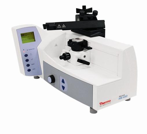
11 PART 1 INTRODUCTION 1-1 DESCRIPTION OF THE SLIDING MICROTOME HM 450 The sliding microtome HM 450 from Thermo Scientific is a highly efficient instrument with specimen retraction during return travel. It can be used for sectioning paraffin in the routine lab. The main applications are in human and veterinary medicine. Moreover, the sliding microtome can be used for the specimen preparation in the medical and industrial research. Large and hard specimens from pharmaceuticals industry or from quality assurance labs can also be sectioned. The cross roller bearings on sledge and block allow non-tiring working and a smooth sliding movement with optimal stability. The HM 450 will cut sections from 0 µm to 100 µm. The specimen clamping can be moved up and downwards via the two arrow-shaped coarse feed buttons on the left side of the instrument. This way, specimen and knife edge distance can be adjusted quickly. The knife carrier is designed so the knives can be easily clamped in place and adjusted. The coaxial specimen orientation allows orientation with one hand. 11
12 1-2 TECHNICAL DATA HM 450 Microtome: Section thickness range:...0,5-100 µm Resolution:... 0,5 µm for 0,5...3 µm... 1 µm for µm... 2 µm for µm... 5 µm for µm µm for µm Retract function for compensating thermal extension:...2 µm Trimming section thickness: µm Resolution:...10 µm for µm...20 µm for 200 µm...50 µm for µm Specimen retraction during return travel...40 µm Vertical feed range mm Horizontal knife stroke mm Cutting drive: Coarse feed: Feed:... manual sliding movement... electronic via stepping motor...automatic via sliding movement or... manual via feed button Specimen size:...up to max. 80 x 60 mm Specimen orientation: x - and y - axes:... universal 8 Transportation- & storage conditions: Storage temperature range: C up to +50 C Operating conditions: C up to +35 C (at a max. rel. humidity of 60%)...altitude up to 2000 m M.S.L....for indoor use only...floor loading requirements: 150 kg/m 2 Power requirements: Internal protections: Secondary circuits: Primary circuits: V V/0,5 A/ Hz/+/-10%... F1 on the power supply unit F 2,5 AH...F1 on CPU board T1.0 AH...F2 on CPU board T2,0 AH... 2 x T 0,63 AH Pollution degree:... 2 Overvoltage category:... II Sound pressure:...39 db(a) measured with 1 m distance to the instrument Dimensions: Weight:...wide: 370 mm, deep: 460 mm, high: 320 mm...23 kg 12
13 PART 2 OPERATING INSTRUCTIONS 2-1 SETTING UP THE MICROTOME Unpack the microtome and remove the wrapping. To carry the instrument, lift it on the front and rear side from the lower side. Warning: Do not carry the instrument on the handle of the knife sledge! Place the instrument on an even surface in a way that the knife guidance is moved towards the user and away from him. The coarse feed arrow buttons and the display should show to the left side and the knife carrier handle to the right side. Choose the installation site so that the mains switch for separating the instrument from the power supply is accessible at any time. Note: Sectioning can be influenced by nearby instruments which generate vibrations. For this reason, the microtome should be placed on a stable and vibration free table. Note: The standard equipment includes four rubber feet which are smaller than the ones that were installed in our factory. Should the working height be too high when setting up the microtome, unscrew the original feet and replace them with the lower ones. 13

14 2-2 INITIAL TURN-ON Note: The kind of the used examination materials and all special conditions for their processing, pre-treatment and, if necessary, storage as well as instrument controls for correct and safe operation is in the responsibility of the operator. The operator is also responsible for special equipment and materials and/or reagents for the operation of the instrument. Microm GmbH Walldorf, Germany Type HM 450 Ser. No. XXXXX Cat. No ,5A/ V Hz Fuse 2 x T 1.6AH Made in Germany Warning: Before turning on the instrument for the first time, please check if the power requirements indicated on the type plate (fig. 2) correspond to the power supply voltage being used! Fig. 2 Connect the power cord to the power socket (fig. 3.2) on the rear side of the instrument. Turn on the power switch (fig. 3.1). Whenever the instrument is turned on, the specimen clamping moves to the lower end position for initialization. Here the instrument type is shown. Afterwards, FEED and TRIM are shown in the normal display mode. The insert for the two fuses is placed beside the power switch. (See part 5, Replacing the fuses). The terms shown on the display are available in German, English and French. If desired, the user can change the language himself. Fig. 3 14
15 2-3 CUTTING MOVEMENT AND RETRACTION To start the cutting movement of the microtome, move the sledge horizontally. The knife (or blade) which is clamped into the knife carrier is drawn horizontally over the specimen towards the user. This way, sections are produced. In the front reversal point of the sliding movement, i.e. when the sledge is moved again backwards, the specimen is retracted for the protection of knife and specimen. If the function <retraction> is active, this is shown by the message R:ON in the normal display mode. If desired, the function <retraction> can be turned off. 15

 into the lower position (fig. 4.2). For this, the red marked lever surface becomes visible to show the clamped state.")
16 2-4 LOCKING THE SLEDGE For the protection against injury by unintended movements of the knife sledge, the microtome is equipped with a lock of the sledge in any position. 1 Caution: The sledge should be locked for the user's personal safety, e.g. when new specimens are clamped into position, knives are exchanged, the instrument is cleaned or other adjustment processes are carried out. The lock is released via a lever on the rear side of the sledge and is easily accessible from the right side behind the handle. 2 Locking the sledge: Swivel the locking lever from the upper position (fig. 4.1) into the lower position (fig. 4.2). For this, the red marked lever surface becomes visible to show the clamped state. Loosening the sledge: Swivel the lever from the lower position (fig. 4.2) into the upper position (fig. 4.1) until the red mark cannot be seen anymore. The knife sledge can be moved again. Fig. 4 16
17 2-4-1 ADDITIONAL BALLAST FOR SLEDGE As required by users to vary the weight of the sledge, we have included additional ballast (Fig ) into the standard equipment. Additional Ballast To assemble the additional ballast, please proceed as described below: Remove the two cover caps, located sideways at the sledge (Fig ). Fig Insert the ballast (Fig ) into the opening and close it again by using the two cover caps (Fig ). Fix the ballast with the laterally set-screw (Fig ) To remove the ballast, please execute this procedure in reverse order. Fig Fig
18 2-5 SETTING SECTION THICKNESS AND TRIMMING THICKNESS The required section thickness and trimming thickness is set via the operating knob on the left side of the instrument. To choose between section thickness and trimming thickness, press the operating knob (fig. 5.1) or the button on the handle. The respective chosen value is now shown with a frame on the display. 1 When the instrument is turned on again, the values which were chosen when the instrument was turned off, are shown again. When turning the operating knob, slight resistances can be felt. FEED = selected section thickness TRIM = selected trimming thickness Fig. 5 The graduation of the section thicknesses is divided into 5 ranges: range graduation from 0,5 µm to 3 µm 0,5 µm from 3 µm to 10 µm 1 µm from 10 µm to 20 µm 2 µm from 20 µm to 60 µm 5 µm from 60 µm to 100 µm 10 µm The graduation of the trimming thicknesses is divided into 3 ranges: range graduation from 10 µm to 100 µm 10 µm from 100 µm to 200 µm 20 µm from 200 µm to 500 µm 50 µm 18
19 2-6 SPECIMEN FEED COARSE FEED AND SPEED FOR COARSE FEED For the fast up and downward travel between specimen and knife edge, the microtome has a coarse feed with vertical direction. 1 The specimen clamping can be moved 40 mm vertically up or downwards via the two coarse feed buttons (fig. 6.1). The specimen is moved upwards as long as the arrow-up-button is being pressed. To move the specimen downwards, press the arrow-down-button. If this button is pressed shorter than one second, the specimen is moved downwards as long as this button is being pressed. If this button is pressed for more than one second, the specimen is moved downwards even after releasing the button until lower end position is reached. This mode is shown on the operating panel by illuminating the red arrow-down. The movement is either automatically stopped when reaching the lower end position or by pressing again one of the two arrow buttons. Fig. 6 Warning: It is not recommended to carry out an exact coarse feed on knife level while the retraction indication lights up. There is the risk to destroy the specimen during the first cuts! Three different speeds for the coarse feed are available: 400, 700 and 1000 µm/s. The three settings are shown on the display by the following symbols: * = 400 µm/s, ** = 700 µm/s *** = 1000 µm/s. 19
20 2-6-2 TRIMMING AND FIRST CUTS After the specimen and the knife are adjusted, further gradual feed for trimming can be carried out using the function "trimming". For different sectioning series, deeper layers of the specimen can be reached with the function "trimming". Warning: It is not recommended to carry out an exact coarse feed on knife level while the retraction indication lights up. There is the risk to destroy the specimen during the first cuts! The function "trimming" can be activated by pressing the operating knob or by pressing the button on the handle. If the instrument is in the manual feed mode, the normal display mode shows MAN. The trimming thickness, which is actually on the display, is delivered in each rear reversal point of the sliding movement as long as the arrow-upbutton is briefly pressed. If the instrument is in the automatic feed mode, AUT is shown in the lower line of the display. The actual thickness, which was selected on the operating knob, is delivered in each rear reversal point of the sliding movement. 20
21 2-6-3 FINE FEED, MANUAL After having adjusted knife and specimen as well as having trimmed the specimen, sectioning can be started. The fine feed can be carried out either manually or automatically. The desired feed mode can be selected via the submenu "Automatic/Manual". When the manual feed mode is activated, MAN is shown in the lower line of the display. The manual fine feed is carried out by briefly pressing the arrow-up-button. To generate sections, move the sledge towards the front FINE FEED, AUTOMATIC When the automatic feed mode is activated, AUT ist shown in the lower line of the display. The feed of the pre-selected section thickness is always automatically carried out in the rear reversal point of the sliding movement, regardless of the position at which the sledge is moved forwards again. Note: For optimal sections, always move the sledge together with the knife to the rear side over the entire specimen and then move it forwards. 21
22 2-6-5 RETRACT FUNCTION FOR COMPENSATING THE THERMAL EXTENSION Normally the ambient air slowly warms up the paraffin specimen which was cooled down before. Due to the rising temperature, the paraffin expands and the achieved sections will be slightly thicker than the pre-selected value. Especially after longer breaks between the sections, a thermal expansion becomes obvious resulting in a thicker first cut at the same section thickness setting. This thermal expansion of the specimen can be compensated by using the retract function. Before starting cutting again, briefly press the arrow-down-button of the coarse feed once. The specimen will be moved by 2 µm downwards away from the knife. Now normal sectioning processes can be started. 22
 blink, when the specimen is just in its upper or lower end position. Another LED (fig. 7.3) shows that the specimen clamping is just in its retraction while the knife sledge is drawn backwards.")
23 2-7 OPERATING PANEL The ergonomically shaped operating panel has a large, illuminated graphical display (fig. 7.1) showing clearly the respective operating states and settings. The two arrow-shaped LEDs (fig. 7.2) blink, when the specimen is just in its upper or lower end position. Another LED (fig. 7.3) shows that the specimen clamping is just in its retraction while the knife sledge is drawn backwards. (Only if retraction is turned on!) Warning: It is not recommended to carry out an exact coarse feed on knife level while the retraction indication lights up. There is the risk to destroy the specimen during the first cuts! Fig. 7 23
24 2-8 KEYBOARD Below-mentioned the four buttons of the operating panel and their meaning signification on the operating panel are described SCROLL BUTTON Via this button (fig. 8) different information (fig. 9) can be called in the second line on the display: current time and date number of sections since the last reset section thickness sum in µm since the last reset available remaining travel in µm blank line RESET BUTTON Via this button (fig. 10) the section counter or the section sum can be reset to zero. Select the desired number via the scroll button so that it is shown on the display. Then press the reset button. The number on the display is reset. Time 16: COUNTER 235 SUM REM.TRAV Fig. 8 Fig. 9 Fig
25 2-8-3 MEMORY BUTTON The memory function (fig. 11) is used to rapidly find again a stored first cut position. Pre-condition for this is that blocks are cut which have been embedded in the same mold and always have approximately the same height. To set the first cut position, press the MEMO button longer until "POSITION STORED" is shown on the display. Finish sectioning, remove the specimen and clamp in a new one. Briefly press the MEMO button to reach the first cut position again rapidly. An arrow symbol on the display shows the direction of the movement. After having reached the stored first cut position, the coarse feed turns off. Fast trimming without time-consuming, gradual feed on the knife is now possible! Warning: The stored first cut position can be used effectively when blocks with the same height are cut. Neither adjustments on the knife carrier must be made nor must the knife carrier be moved on the dovetail guide. Caution: When changing the knife angle, a new first cut position must be selected as otherwise the danger of a collision with injuries might arise. MEMO Fig. 11 reasons. Warning: When turning on the instrument later again, the first cut position must be defined and stored again for safety 25
26 2-8-4 MENU BUTTON Via the menu button (fig. 12) you have access to further settings which are described below. Normally these settings are made when starting to work and do not have to be altered while sectioning. In the respective submenus, options can be changed by turning the selection knob to the left side or to the right side and can be confirmed by pressing this knob (ENTER). MENU Fig Automatic/Manual Herewith the automatic feed is turned on or off. The options are shown as in the opposite list (fig. 14). Note: If the automatic feed is turned on (AUT), a feed of the selected section thickness is delivered when the knife sledge is moved from the return travel into cutting direction. Press the menu button. The submenu is shown on the display. Select "Process mode" (fig. 13) via the selection knob and confirm it by pressing the knob. If the automatic feed is turned off (MAN), briefly press the arrow-up-button to release a manual feed of the selected section thickness. The selected mode is permanently shown by AUT or MAN in the normal display mode. Process mode AUT Fig. 13 Automatic/Manual Automatic turned on AUT Automatic turned off MAN Fig
27 RETRACTION ON/OFF The instrument is equipped with an electronic retraction which can be turned off. During the return travel of the knife, the specimen is drawn back (away from the knife). This way, the knife does not touch the specimen surface during its return travel. When the knife movement is reversed for the return travel, the retraction is released without having to pass a certain point. To activate the retraction, just alter the direction. The retraction process can be heard during each direction alteration by a short click of the stepping motor. It can also be seen via the retraction LED. Retraction R:ON Fig. 15 RETRACTION Retraction turned on R:ON Retraction turned off R:OF Fig. 16 Press the menu button. The submenu (fig. 15) is shown on the display. Select "Retraction" via the selection knob and confirm it by pressing this knob. 27
28 SPEED FOR COARSE FEED In this menu, the speed for the coarse feed can be selected in three different settings. Turn the selection knob to alter the number of the indicated stars (fig. 17). They correspond to the different speeds according to the opposite list (fig. 18). Press the selection knob to confirm the indicated setting LANGUAGE SELECTION Here the respective language of the display messages can be selected (fig. 19). The following languages are available: German English French Turn the selection knob and select the desired language. Press the selection knob to confirm the desired setting. Speed SPEED FOR COARSE FEED Coarse feed speed 400 µm/s * Coarse feed speed 700 µm/s ** Coarse feed speed 1000 µm/s *** Language ENGLISH Fig. 17 Fig. 18 Fig
 shows the selected feed and trim thicknesses with additional status indications. The big display mode (fig.")

 Coarse feed speed Fig.")
29 SELECTING THE DISPLAY MODE Here the display mode NORMAL and BIG can be selected (fig. 20). The normal display mode (fig. 21) shows the selected feed and trim thicknesses with additional status indications. The big display mode (fig. 22) only shows the active section thickness with a large number together with a symbol for the feed or trim thickness range. Press the menu button. The submenu is shown on the display. Select "Display mode" via the selection knob and confirm it by pressing this knob. Return with another press on the menu button. Display mode NORMAL NORMAL Section thickness, feed is currently active Fig. 20 Feed mode AUT / MAN Additional indication can be selected via the scroll button Retraction on/off (R:ON/R:OF) Coarse feed speed Fig. 21 BIG Thickness range symbol for fine and trim thickness Indication of section thicknesses in large numbers Fig
30 TIME AND DATE With this menu the current time as well as the current date (fig. 23) can be set. Press the menu button. The submenu is shown on the display. Select "Time & Date" via the selection knob and confirm the setting by pressing this knob. Note: In the normal display mode, the current time can be shown constantly via the scroll button. Time & Date 14: Fig SERVICE MENU This submenu must only be used by technical personnel which has been trained by Thermo Scientific, as it contains diagnostics for error cases. Caution: It is not recommended for nontechnically trained personnel to use this submenu. 30
31 2-9 SPECIMEN CLAMPING To clamp specimens, different specimen clamping systems are available. With the orienting adapter it is simple to align the specimen properly in relation to the knife STANDARD SPECIMEN CLAMP (Cat. no ) The standard specimen clamp is used for rectangular and square paraffin blocks. Insert the specimen on the front fixed jaw (fig. 24.2) and tighten it via the clamping screw (fig. 24.3) with the movable jaw (fig. 24.1) Warning: For the stability of the specimen, do not let it project over the clamping jaws too much! Fig STANDARD SPECIMEN CLAMP This specimen clamp is used in the same way as the above-described standard specimen clamp (see cat. no ). The clamping screw and thus the clamping direction of this clamp is arranged transversely in relation to the sectioning direction. Specimens with a size up to 45 x 60 mm can be inserted. Warning: For the stability of the specimen, do not let it project over the clamping jaws too much! 31
32 2-9-3 UNIVERSAL CASSETTE CLAMP (Cat. no ) The universal cassette clamp represents a quick change system for standardized embedding cassettes. To insert or remove cassettes, press the lever (fig. 25.1) upwards. 1 Warning: When inserting the universal cassette clamp, please note that the lever (fig. 25.1) is always in parallel alignment with the movement direction of the knife sledge. If the clamp is inserted diagonally in relation to the cutting direction, the feed drive might block! Fig
. Set the specimen clamp horizontally by means of the set screws of the orientation device.")
33 2-10 CHANGING SPECIMEN CLAMPS Due to the quick change system of the specimen clampings, specimen clamps can be easily and rapidly changed without needing any tools. Loosen the clamping of the specimen clamp (fig. 26.1). Set the specimen clamp horizontally by means of the set screws of the orientation device. To replace the specimen clamp turn the eccentric lever downwards (fig. 26.1) to the stop and pull it off (fig. 26.2). Now the specimen clamp can be removed and replaced with another one. Note: Before inserting another clamp, please note the position of the hole in the adapter! It must be aligned in longitudinal direction of the instrument so that the eccentric lever can be pushed in again. Again push the eccentric lever into the specimen block. Then press the eccentric lever upwards to fix the specimen clamp in position. 1 2 Fig

. Inserting the knife Fig. 27 To insert the knife, slightly unscrew the two clamping screws (fig.")
34 2-11 KNIFE CARRIER Hazard of hand injuries: Due to moving parts in connection also with the microtome knife, a danger area arises, which might lead to hand injuries in case of non-compliance with the safety features of the microtome and when disregarding the instruction manual. The knife carrier of the microtome is easy to use and equipped with a knife guard for user safety while adjusting knife and specimen. Caution: While working on the knife carrier, it should be locked with the sledge locking (see part 2-4). Inserting the knife Fig. 27 To insert the knife, slightly unscrew the two clamping screws (fig. 27.1) until the knife can be pushed in from the side. Then tighten the two clamping screws to fix the knife in its position. Clearance angle adjustment The clearance angle between cutting edge and specimen can be adjusted very easily to the respective requirements of the tissue to be sectioned without loosening the clamping of the knife. For this, use the two coaxial screws (fig and 27.3) on the upper side of the knife carrier. Loosen the clamping screw (fig. 27.3) in a counter-clockwise direction and adjust the clearance angle by means of the set screw (fig. 27.2). The adjusted clearance angle can be read on the scale which is on the right side of the knife carrier. Then tighten the screw (fig. 27.3) in clockwise direction to fix the clearance angle. Note: By experience, usable cuts are only achieved at a clearance angle of 10 or more. 34
35 Protection against injury The knife carrier is equipped with a knife guard (fig. 27.4) which should be used while knife or specimen are adjusted. Caution: Please note that knives with a length of more than 16 cm (e.g. 22 cm) and/or if it is clamped too much on one side, projects over the knife guard resulting in possible hazards of being injury although the knife guard is used. Moving the knife sideways If the cutting edge of the knife is blunt, loosen the clamping screws (fig. 27.1) and move the knife to the left or right side. This process can also be used to protect the knife, as for trimming and fine sectioning different parts of the knife can be used. Diagonal position of the knife After having loosened the central fastening screw of the knife carrier (5) via the attached hex head wrench (size 6), the knife can be adjusted diagonally according to the tissue to be sectioned. This is called "angle cut". However, please note that due to the diagonal positioning the usable width of the specimen decreases! Height adjustment plates (optional) In case the height adjustment of the specimen block is not sufficient for cutting high specimens, a height adjustment plate can be mounted between knife carrier and sledge. Height adjustment plates are available with 5 mm, 10 mm and 20 mm. Knife profile Knives with profile c and d are available. The opposite figure (fig. 28) shows schematically the angles on the cutting edge profiles of c- and d- knives. Fig
36 BLADE HOLDER FOR DISPOSABLE BLADES Two different types of disposable blades are available: low profile blades (height: 8 mm) and high profile blades (height: 14 mm). When using disposable blades, a blade holder together with a disposable blade is clamped into the knife carrier. Inserting the blade Insert the blade holder into the knife carrier from the left side and tighten the two clamping screws on the knife carrier. The clamping lever on the blade holder can be positioned in two ways: 0 = loosened, 1 = clamped. To insert the blade, turn the clamping lever to 0. Please note that locating and clamping surfaces are clean!! To clamp the blade, turn the clamping lever to 1. Clearance angle adjustment The clearance angle between blade and specimen must be adjusted in the same way as the clearance angle between knife and specimen is adjusted. Protection against injury The knife carrier of the instrument is equipped with a knife guard which can be moved sideways. This knife guard should be used while knife and specimen are adjusted. This reduces the danger of injury considerably! 0 MICROM Fig
37 2-12 STANDARD EQUIPMENT The sliding microtome HM 450 is supplied with the following accessories: 1 hex head wrench 5 mm 1 hex head wrench 6 mm 1 cover 4 rubber feet with lower height 1 instruction manual 2-13 ADDITIONAL EQUIPMENT (OPTIONAL) DISPOSABLE BLADE HOLDER Cat. no. Blade holder with eccentric fast clamping - for low profile blades for high profile blades Case for disposable blade holder Cat. no and Blade holder with Allen key - for one low profile blade for two low profile blades SPECIMEN CLAMPS Universal cassette clamp Standard specimen clamp, 45 x 80 mm
38 HEIGHT ADJUSTMENT PLATES 5 mm mm mm MICROTOME KNIVES Steel knives, type c 12 cm cm ,5 cm cm cm cm Steel knives, type d 12 cm cm cm cm cm Tungsten carbide knife 16 cm, d Knife case 12 cm cm ,5 cm cm cm cm Disposable blades for paraffin SEC SEC 35e SEC 35p ADDITIONAL ACCESSORIES Fast freezing unit KS 34 S (standard specimen clamp is necessary) Para Gard (paraffin repellent), 100 ml
39 Sliding Microtome HM 450 PART 3 THEORY OF OPERATIONG 3-1 CUTTING MOVEMENT The electronic sliding microtome HM 450 has a high-precise, zero-backlash linear roller bearing (cross roller bearing) for the bearing of the knife sledge and the block These cross roller bearings allow a zero-backlash feed of the knife sledge. The knife sledge cannot be removed from the user, however, it is restricted guided and always remains on the instrument. The cutting movement of the microtome is generated by horizontally moving the sledge in the cross roller bearings. Here the knife, which is clamped into the knife carrier, is horizontally drawn over the specimen towards the user and away from him. This way, sections are produced. After having moved the knife sledge backwards into the rear end position, a pre-selected section thickness is carried out either manually by pressing a button or automatically due to the alteration of the direction of the knife sledge. The specimen is delivered towards the knife with the pre-selected section thickness in vertical direction and a new section is produced. 3-3 SPECIMEN CLAMPING SYSTEM AND SPECIMEN ORIENTATION According to the form and size of the specimens, different specimen clamping systems are available to carry the specimen. It is very easy to align the specimen to the knife, using the orienting adapter. 3-4 KNIFE CARRIER The knife carrier is easy to use and allows the microtome knives to be clamped and adjusted as needed. Depending on application, knives or disposable blades can be used. 3-5 MICROTOME WITH FAST FREEZING UNIT The fast freezing unit K 400 allows frozen sectioning with the specimen temperature as low as -45 C. 3-2 SPECIMEN COARSE FEED AND TRIMMING FUNCTION After changing the specimen or moving the knife or knife carrier, it is necessary to adjust the specimen to the knife edge again. This can easily be done by means of the specimen coarse feed and the defined trimming values. After the specimen and the knife are adjusted, further gradual feed for trimming can be carried out.
40 PART 4 WORKING WITH THE MICROTOME 4-1 PREPARATION AND ORIENTATION Before sectioning, the specimens must be prepared appropriately and embedded in suitable media. Cassettes as well as different forms for round and rectangular specimens can be used for embedding. With the orienting adapter, the specimen can easily be oriented to the knife. 4-2 COARSE FEED AND TRIMMING FUNCTION To adjust approximately the space between specimen and cutting edge, use the coarse feed or the trimming function. Continue this to start trimming the specimen, thus achieving the level of interest. Any waste should be wiped away in a forward direction with a brush. 4-3 SECTIONING INSTRUCTIONS Hazard of hand injuries: Due to moving parts in connection also with the microtome knife, a danger area arises, which might lead to hand injuries in case of non-compliance with the safety features of the microtome and when disregarding the instruction manual. To cut usable sections, the following points are of utmost importance: CONDITION OF THE KNIFE EDGE Only use a sharp knife! If the knife edge is blunt, move the knife horizontally either to the right or left side to continue working with the sharp area of the cutting edge, or have the knife resharpened CLEAN KNIFE SURFACES For optimal sectioning, front and back of the knife must be clean. Especially, paraffin waste must be removed thoroughly!! 40
41 4-4 HOW TO AVOID MALFUNCTIONS Note: In case of malfunctions and/or service work, please turn off the instrument and contact your local dealer ADJUSTMENT OF THE KNIFE Take care to adjust the proper clearance angle of the knife. Select a clearance angle adjustment of 10 or more according to the facet angle PREPARATION OF THE SPECIMEN When preparing specimens, be sure that a suitable embedding medium, fixation, dehydration and infiltration time are chosen CUTTING SPEED Take care to select proper cutting speed. General Rule: The harder the material, the slower the cutting speed!! TEMPERATURE OF THE SPECIMEN Sectioning is carried out at ambient temperature (excluding frozen sections). If the temperature is too high, the paraffin softens. Therefore, avoid heating paraffin specimens by direct exposure to sunlight or other near sources of heat TRIMMING Take care in bringing the knife and specimen together TIGHTENING THE CLAMPING SCREWS Tighten all clamping screws and clamping levers on the knife carrier, specimen holder and specimen orientation SELECTION OF THE KNIFE Carefully select the required knife material and profile. 41
42 PART 5 MAINTENANCE Annual routine maintenance To secure section quality and functioning of the microtome, it is recommended that a routine maintenance be performed by a trained service technician once a year. Service contract Thermo Scientific offers a service contract which guarantees that your instrument is always in perfect condition. For more information, please contact the nearest Thermo Scientific sales office. EXCHANGE OF FUSES Fig. 30 The two mains fuses are installed on the back of the instrument beside the power switch (fig. 30.1). To exchange the two fuses, turn off the power switch of the instrument and unplug the instrument. Open the small cover (fig. 30.2) of the fuse holders from the right side (see arrow) by means of a flat screw driver. Pull out the fuse holders, each of which is marked with an arrow and exchange the fuses against new ones. Rating of fuses: For power requirements V: 2 x T 1.6 AH 42
43 PART 6 CLEANING AND CARE Cleaning intervals Cleaning, care and decontamination of the microtome depends on how frequently the microtome is used. For optimal sectioning, the instrument must be free of section waste, especially the guides and clamping mechanism. Cleaning agents Mild household cleaners can be used to clean the microtome. Do not use aggressive cleaners or solvents, as the paint and plastic parts can be affected. Note: Before starting cutting, instrument, knife carrier and section waste trays should be treated with a commercially available paraffin repellent, e.g. Para Gard. Care Remove the knife from the knife carrier. Clean it with a dry cloth to avoid the formation of rust and keep it in a knife case. Caution: Never put the knife with the cutting edge upwards on the table! Clean the operating controls and the surfaces of the knife carrier, especially the space where the knife is installed. The maintenance-free cross roller bearings are covered and protected against dust and section waste and need not to be lubricated or cleaned by the customer. Clean the specimen clamping system, specimen orientation, housing and vertical carrier. 43
44 PART 7 CONDITIONS FOR THE TRANSPORTATION OF THE INSTRUMENT 7-1 TAKING BACK THE INSTRUMENT FOR REPAIR OR ROUTINE MAINTENANCE Repair or maintenance works are normally carried out at the site of installation. If this is not possible for some special reasons, the instrument can be returned to Thermo Scientific. The contact address can be found at the beginning of this instruction manual. To guarantee trouble-free function of the instrument after transportation, please note the below-mentioned measures for the transportation preparation. In addition, the conditions for storage and transportation as mentioned in part 1-2 must be observed during the entire transportation. Biohazard: Please also note the precautionary measures described in our safety precautions concerning biological hazards! Measures for closing down: Caution: Any shipping of the instrument requires original packaging materials! Damages caused by shipping with non-conform packaging are not covered by the manufacturer warranty! Any damage repairs resulting in non-conforming package are fully charged to the sending party. We reserve the right depending on seriousness of damage NOT to repair. To order original packaging materials, please contact Thermo Scientific l or your local, by Thermo Scientific authorized, dealer. Caution: The user must care for a clean and safe condition of the instrument when returning it to an appropriate service provider. Note: If the original packaging is no longer available, please contact your local Thermo Scientific representation. Turn off the instrument. Unplug the unit. Remove knife or blade and store it in a safe way. Secure the sledge via the lock of the sledge as described in part 2-4. Note: The locking of the sledge functions as a brake. In case the instrument is kept in an inclined way, the braking power might not be sufficient enough to avoid that the sledge moves. To lift the instrument, take it on each fore-parts. During transportation, do not carry the instrument on the handle. Danger of injury! 44
45 For transportation outside closed buildings, please observe the following additional measures: Turn off the instrument. Unplug the unit. Remove knife or blade and store it in a safe way. Secure the sledge via the transportation safety sheet: Place the sheet onto the specimen holder. Move the sledge into a position so that the holes correspond with each other and tighten the screws. Note: The locking of the sledge is functions as a brake. In case the instrument is kept in an inclined way, the braking power might not be sufficient enough to avoid that the sledge moves. To lift the instrument, take it on each fore-parts. During transportation, do not carry the instrument on the handle. Danger of injury! Pack the instrument into the original packing as it offers best pre-conditions for transportation without damage. Note: If the original packing is no longer available, please contact your local Thermo Scientific representation. 45

46 7-2 DISPOSAL OF THE INSTRUMENT AFTER FINAL SHUTDOWN After the final shutdown of the instrument, we recommend to contact a local recycling company for the disposal according to the national applicable regulations. To be applied in the countries of the European Union and other European countries with a separate collecting system within the waste management. The marking of the product and/or the respective literature indicates that, after its final shutdown, it must not be disposed of together with ordinary domestic waste. Please dispose of your instrument separately from other waste to not harm our environment and/or human health by uncontrolled waste disposal. Recycle your instrument to support the sustainable recycling of material resources. Industrial users should contact their suppliers and observe the conditions of the contract. This product must not be disposed of together with other commercial waste. Please contact your supplier!! 46
TN5000 Titan Manual Rotary Microtome
 User Manual TN5000 Titan Manual Rotary Microtome Read Prior to Operation! Always keep this manual near the unit! WP47617 06.02.15 User Manual TN5500: Titan 888.708.5233 Info@TannerScientific.com www.tannerscientific.com
Leica CE/ Leica CN. Knife holder
 Leica CE/ Leica CN Knife holder Instruction Manual Leica knife holder CE/ knife holder CN V2.2 English 08/2005 Always keep this manual near the instrument. Read carefully prior to operating the knife holders.
Product instruction manual Ream Cutting Systems RE3943, RE3946, RE3947, RE3971, RE3952E
 Product instruction manual Ream Cutting Systems RE3943, RE3946, RE3947, RE3971, RE3952E The Trimfast Ream Cutters are reliable, high performance cutters that will give you the results you need quickly
Operator s Manual. Medium-Duty Electric Slicers ENGLISH. Item Model Description Drive Peak HP Voltage Amps Hz Plug
 Medium-Duty Electric Slicers 40950 40951 Item Model Description Drive Peak HP Voltage Amps Hz Plug 40950 SLM250/S 10 Knife Medium-Duty Slicer 1/3 2.5 Belt 120 60 5-15P 40951 SLM300P/S 12 Knife Medium-Duty
AFC-50 Automatic French Fry Cutter Instruction Manual
 AFC-50 Automatic French Fry Cutter Instruction Manual Fry Factory Inc. 67 Watts Ave, Charlottetown, PEI, C1E 2B7, Canada Phone: 902-368-2900 Fax: 902-368-8645 Email: info@fryfactoryinc.com Website: www.fryfactoryinc.com
S E L E C T I O N. Abdominal Crunch. User manual
 and S E L E C T I O N T H E S T R E N G T H E V O L U T I O N User manual and and The identification plate of the and manufacturer, affixed along side the seat on the frame of the weight stack, gives the
electric knife sharpener
 electric knife sharpener USER GUIDE Now that you have purchased a Kitchen Living product you can rest assured in the knowledge that as well as your year parts and labour guarantee you have the added peace
Instructions for Cryostat Slicing Leica Model CM 3050S
 Instructions for Cryostat Slicing Leica Model CM 3050S Set-up: 1. Make sure cryostat is on and cold (-15 to 20 degrees C). Place tissue to be sliced in chamber to bring it to temperature (tissue stored
1000M MANUAL Signature Series Slicer OPERATORS MANUAL
 1000M MANUAL Signature Series Slicer OPERATORS MANUAL Persons under age 18 are not permitted to operate or have accessibility to operate this equipment per U.S. Dept. Of Labor Employment Standards Administration
MAX Series 9514 OPERATOR S MANUAL
 MAX Series 9514 OPERATOR S MANUAL Persons under age 18 are not permitted to operate or have accessibility to operate this equipment per U.S. Dept. Of Labor Employment Standards Administration Fact Sheet
Meat Slicer INSTRUCTION MANUAL CAUTION! ONE YEAR LIMITED WARRANTY
 ONE YEAR LIMITED WARRANTY INSTRUCTION MANUAL The original registered owner of this product should contact SKYFOOD EQUIPMENT LLC at 305-868-16 for any warranty problems or service. SKYFOOD EQUIPMENT LLC
functionality with the necessary maintenance tools stored in a convenient built in tool box, as well as parallel handles for
 GuilloMax User Manual The Guillomax has distinct features such as its unique structure and ease of cutting. It combines symmetry with functionality with the necessary maintenance tools stored in a convenient
PS-10 PS-12D PS-12. Primo Slicer Manual FOR OPERATOR-DO NOT DISCARD
 PS-10 PS-12D PS-12 Primo Slicer Manual FOR OPERATOR-DO NOT DISCARD TABLE OF CONTENTS 1. BRIEF INTRODUCTION 2. OPERATION 3. SLICING 4. MAINTENANCE AND CLEANING 5. TROUBLESHOOTING IMPORTANT The operator
Installation and User s Manual 12 x 10 MOTORIZED AWNING
 12 x 10 MOTORIZED AWNING Installation and User s Manual 12 x 10 MOTORIZED AWNING 088-1763-0 Stop Please read and understand this manual before any assembly or use of this product. Before beginning assembly
LDR Brachytherapy Seed Sterilization and Sorting Tray
 LDR Brachytherapy Seed Sterilization and Sorting Tray Table of Contents General Precautions... 2 Customer Responsibility... 3 Description... 4 Features and Specifications... 5 Operation... 6 Changing Covers
NEWMAR SERVICE SCHOOL
 NEWMAR SERVICE SCHOOL TRAINING INFORMATION GUIDELINE FOR FEBRUARY 2013 OUR PRODUCTS: NOVA DUAL PITCH AWNING G-2000/ G-1500 2 P a g e G-2085 G-5000 3 P a g e G-LINKS 4 P a g e NOVA/ G-2000/ G-1500 BASIC
Please read this guide carefully. It tells you how to prepare your cutting plotter for production use in a few easy steps.
 OPERATING GUIDE for Secabo mini Cutting Plotter Congratulations on purchasing your Secabo mini cutting plotter! Please read this guide carefully. It tells you how to prepare your cutting plotter for production
RM 2125 Troubleshooting Guide
 Problems, possible causes and corrective action Problem Cause Corrective Action 1) Thick and Thin Sections. a) Partial Sections b) Shorter Sections in ribbon c) Section thickness varies from one section
Electric 2-STAGE SHARPENING FEATURES: system allows for safe, easy knife sharpening - Non-slip feet allows sharpener to stay in place while in use
 Electric FEATURES: - 2-Stage electric sharpening system allows for safe, easy knife sharpening - Non-slip feet allows sharpener to stay in place while in use 2-STAGE SHARPENING IMPORTANT SAFEGUARDS SAVE
1612P MODEL 1612P SLICER MODEL EXECUTIVE OFFICES 701 RIDGE AVENUE TROY, OHIO FORM (4-95)
") 1612P MODEL 1612P SLICER MODEL 1612P ML-104587 EXECUTIVE OFFICES 701 RIDGE AVENUE TROY, OHIO 45374-0001 FORM 19370 (4-95) Installation, Operation, and Care of MODEL 1612P SLICER SAVE THESE INSTRUCTIONS
1612P MODEL 1612P SLICER MODEL 1612P ML-104587 EXECUTIVE OFFICES 701 RIDGE AVENUE TROY, OHIO 45374-0001 FORM 19370 (4-95) Installation, Operation, and Care of MODEL 1612P SLICER SAVE THESE INSTRUCTIONS
FORM (Apr. 2006)
") 2212 Slcier MODEL 2212 SLICER MODEL 2212 ML-136132 701 S. RIDGE AVENUE TROY, OHIO 45374-0001 937 332-3000 www.hobartcorp.com FORM 35215 (Apr. 2006) Installation, Operation, and Care of MODEL 2212 Slicer
2212 Slcier MODEL 2212 SLICER MODEL 2212 ML-136132 701 S. RIDGE AVENUE TROY, OHIO 45374-0001 937 332-3000 www.hobartcorp.com FORM 35215 (Apr. 2006) Installation, Operation, and Care of MODEL 2212 Slicer
USER MANUAL BMU WORKCAGE. CONFORM TO THE MACHINE DIRECTIVE 2006/42/EC and to EN1808 (1999)
") USER MANUAL BMU WORKCAGE CONFORM TO THE MACHINE DIRECTIVE 2006/42/EC and to EN1808 (1999) All persons operating this equipment must read and completely understand this manual. Any operation in violation
USER MANUAL BMU WORKCAGE CONFORM TO THE MACHINE DIRECTIVE 2006/42/EC and to EN1808 (1999) All persons operating this equipment must read and completely understand this manual. Any operation in violation
RM2235. Rotary Microtome. Instructions for Use
 Instructions for Use RM2235 Rotary Microtome Leica RM2235 V 2.1, English 11/2015 Order No.: 14 0500 80101 RevF Always keep this manual with the instrument. Read carefully before working with the instrument.
Bevel Buddy Instruction Manual
 Bevel Buddy Instruction Manual We at Precision Sharpening Devices Inc. believe there are two very important steps in maximizing the savings this equipment can provide your company. First, use this manual
Leica RM2125 RTS. Rotary Microtome. Instructions for Use
 Instructions for Use Leica RM2125 RTS Rotary Microtome Instructions for Use Leica RM2125 RTS V 2.5, English - 09/2018 Order No. 14 0457 80101 RevH Always keep this manual with the instrument. Read carefully
Installation & Operation Manual VHM Variable Height Series Arms with Fixed Angle Front End
 3875 Cypress Drive Petaluma, CA 94954 800.228.2555 707.773.1100 Fax 707.773.1180 www.gcx.com Installation & Operation Manual VHM Variable Height Series Arms with Fixed Angle Front End Products covered
ELECTRIC KNIFE SHARPENER User Guide
 BRAND ELECTRIC KNIFE SHARPENER User Guide Item: 717822 Ginnys.com 800-544-1590 Facebook.com/GinnysBrand Pinterest.com/GinnysBrand Ginnys.com/Blog Thank you for purchasing a Ginny s Brand Electric Knife
SPIRAL SLICER Instruction Manual Model #5280 & 5280M. Part No Revised Feb. 2010
 SPIRAL SLICER Instruction Manual Model #5280 & 5280M Part No. 82876 Revised Feb. 2010 SAFETY PRECAUTIONS INSTALLATION INSTRUCTIONS Inspection of Shipment: 5280 & 5280M SPIRAL SLICER Unpack all cartons
Setup. Assembling. Attaching the sharpening stone
 Kit 1. Sharpener base. 2. Vertical rod. 3. Fixing ring. 4. Horizontal rod with pivot unit. 5. Sharpening stones set. 6. Black marker. 7. User Guide. Technical specs Knife sharpener dimensions (ready to
Please read this guide carefully. It tells you how to prepare your cutting plotter for production use in a few easy steps.
 OPERATING GUIDE for Secabo C30 and C40 cutting plotters Congratulations on purchasing your Secabo cutting plotter! Please read this guide carefully. It tells you how to prepare your cutting plotter for
Thomas Scientific Swedesboro, NJ U.S.A.
 Thomas Scientific Swedesboro, NJ 08085-0099 U.S.A. Wiley Laboratory Mill, Model 4 3375-E10 (115 V, 50/60 HZ) USE AND CARE OF CATALOG NUMBER: 3375-E10 Wiley Laboratory Mill, Model 4 (115 V, 50/60 HZ) UNPACKING
Est A TRADITION OF EXCELLENCE INSTRUCTION BOOK.
 Est. 1887 A TRADITION OF EXCELLENCE INSTRUCTION BOOK www.wolseleygrooming.co.uk Stockshop (L.E.) Ltd., Lodge Trading Estate, Broadclyst, Exeter EX5 3BS Email: service@stockshop.co.uk Tel: 01392 460077
Cassette-folding arm-awning markilux 990
 Cassette-folding arm-awning markilux 990 Mounting instructions 1. Overview 1 Projection profile 2 Folding arm 3 Fabric 4 Console 5 Cassette 6 Covering cap 7 Wall bracket 2. Mounting brackets 2.1 Overview
I N ST R UC T I ON MODELS 1612E, 1712E & 1712RE SLICERS. FORM Rev. B (10-97) 1712RE 701 S. RIDGE AVENUE TROY, OHIO 45374
 1712RE 701 S. RIDGE AVENUE TROY, OHIO 45374") I N ST R UC 1712E T I ON MODELS 1612E, 1712E & 1712RE SLICERS S ML-104546 ML-104547 ML-104548 1612E 1712E 1712RE 701 S. RIDGE AVENUE TROY, OHIO 45374 FORM 19238 Rev. B (10-97) TABLE OF CONTENTS GENERAL......................................................................
I N ST R UC 1712E T I ON MODELS 1612E, 1712E & 1712RE SLICERS S ML-104546 ML-104547 ML-104548 1612E 1712E 1712RE 701 S. RIDGE AVENUE TROY, OHIO 45374 FORM 19238 Rev. B (10-97) TABLE OF CONTENTS GENERAL......................................................................
PRODUCT MANUAL - M096
 PRODUCT MANUAL - M096 MODEL 270 ELECTRIC CAN OPENER 1 I. LABELS L087--CAUTION 2 II. SPECIFICATIONS MODEL NO. 270 POWER 115 VOLT, 1.5 AMP, 50-60HZ REQUIREMENTS 230 VOLT, 0.8 AMP, 50-60 HZ NORMAL SPEED 200-250
User Manual. Meat Slicer Instruction Manual. Model: 177SL612A 10/2018. Please read and keep these instructions. Indoor use only.
 Meat Slicer Instruction Manual Model: 177SL612A 10/2018 Please read and keep these instructions. Indoor use only. www.avantcoequipment.com 1 Unpacking: Unpack the product and check for any damage incurred
Legacy Basic Acoustical Shell
 Owner s Manual Legacy Basic Acoustical Shell CONTENTS Safety Precautions.................................. 2 General....................................... 2 Set Up and Usage..............................
MYRIAD Banner Stand is a trademark of Skyline Exhibits. Patent Pending PN32294-B. MYRIAD Banner Stand
 is a trademark of Skyline Exhibits Patent Pending 1.1 1. Banner Stand Setup 1.1 Remove banner stand from standard case or Arrive Portable Display & Workstation and assemble pole. 1.2 Insert pole into base
PATRIOT INSTRUCTION MANUAL SL300C 12 MEAT SLICER 1/2 HP
 INSTRUCTION MANUAL SL300C 12 MEAT SLICER 1/2 HP This manual contains important information regarding your Patriot unit. Please read this manual thoroughly prior to equipment set-up, operation and maintenance.
THE EDGE12 SLICER. MODEL EDGE12-2 (220/50/1 voltage) FORM (July 2012) EDGE12 SLICER
 FORM (July 2012) EDGE12 SLICER") EDGE12 SLICER THE EDGE12 SLICER MODEL EDGE12-1 (120/60/1 voltage) EDGE12-2 (220/50/1 voltage) ML-136246 ML-136247 701 S. RIDGE AVENUE TROY, OHIO 45374-0001 937 332-3000 www.hobartcorp.com FORM 35283 (July
EDGE12 SLICER THE EDGE12 SLICER MODEL EDGE12-1 (120/60/1 voltage) EDGE12-2 (220/50/1 voltage) ML-136246 ML-136247 701 S. RIDGE AVENUE TROY, OHIO 45374-0001 937 332-3000 www.hobartcorp.com FORM 35283 (July
Cordless Electric Teakettle. Model 685
 Cordless Electric Teakettle Model 685 Important Safeguards When using electrical appliances, basic safety precautions should always be followed, including the following: 1. Read all instructions. 2. Do
Sectioning Paraffin Blocks
 Description Laboratory Standard Operating Procedure for: Sectioning Paraffin Blocks This SOP requires a Designated Trainer! This SOP describes how to section tissue embedded in paraffin wax with a Leica
DIAMOND TECH INTERNATIONAL Innovations For Creativity DIAMOND LASER BAND SAW OPERATIONS MANUAL
 SPEEDSTER-XL INSTRUCTION MANUAL DIAMOND TECH INTERNATIONAL Innovations For Creativity SPEEDSTER-XL DIAMOND LASER BAND SAW OPERATIONS MANUAL SPEEDSTER-XL INSTRUCTION MANUAL - PAGE 1 Before You Begin Read
Urea/Adblue Hose Reel
 www.scintex.com.au sales@scintex.com.au Model: SHR3408 Urea/Adblue Hose Reel Product Manual Specifications Spring driven drum: for automatic rewind. Locking ratchet: to maintain the desired length of hose
quick and easy installation guide
 www.directdriveopener.com quick and easy installation guide Back 2 Front. Motor Carriage 2. C-rail. Chain. Limit stops. Slide in part (tensioner) Rail assembly Insert C-rail parts () into the connecting
View slicer 800-S. meat pusher. handle. thumb. screw. sharpener. table release. handle. securety. screw. knifescraper
 View slicer 800-S meat pusher handle thumb screw sharpener securety screw table release handle knifescraper control on knob off knob thickness lamp regulator knob safety guard ddddddd meat table knife
Tidland Series 'C' Knifeholder MAINTENANCE MANUAL Crush Cartridge Class I, II, III Crush Slitting
 Tidland Series 'C' Knifeholder MAINTENANCE MANUAL Crush Cartridge Class I, II, III Crush Slitting Please read and understand all the instructions before you start to maintain the Tidland Series 'C' Knifeholder.
INSTRUCTION MANUAL ALEKO RETRACTABLE AWNING
 INSTRUCTION MANUAL for ALEKO RETRACTABLE AWNING www.alekoproducts.com FAILURE TO FOLLOW THESE INSTRUCTIONS MAY RESULT IN PERSONAL INJURY! 1 Important Safety Precautions WARNING NOTE: FOR PERSONAL SAFETY,
Primrose Awnings - Full Cassette Manual & Electric Instructions
 Primrose Awnings - Full Cassette Manual & Electric Instructions Contents Warning 2.0m - 3.5m Awnings 8 x Expansion bolts ** 2 x brackets 1 x Awning 1 x Winder 4.0m - 5.0m Awnings 12 x Expansion bolts **
SAFETY AND OPERATING MANUAL
 SAFETY AND OPERATING MANUAL General Safety Rules WARNING! Read all instructions. Failure to follow all instructions listed below may result in electric shock, fire and/ or serious injury. The term power
FORM Rev. A (Feb. 2004)
") 2812B SLICER MODEL 2912B SLICER MODEL 2912B SLICER MODEL 2912B ML-134251 ML-134252 Previous models covered by this manual: 2912B ML-134123 701 S. RIDGE AVENUE TROY, OHIO 45374-0001 937 332-3000 www.hobartcorp.com
2812B SLICER MODEL 2912B SLICER MODEL 2912B SLICER MODEL 2912B ML-134251 ML-134252 Previous models covered by this manual: 2912B ML-134123 701 S. RIDGE AVENUE TROY, OHIO 45374-0001 937 332-3000 www.hobartcorp.com
IMPORTANT NOTICE. Professional Mandoline Manual
 IMPORTANT NOTICE PLEASE DO NOT RETURN TO STORE. If you have any problems with this unit, contact Consumer Relations for service. PHONE: 206-605-0555 Please read operating instructions before using this
Professional Mandoline Manual. Model: 90757
 Professional Mandoline Manual Model: 90757 Introduction Your MIU France Composite Mandoline features a selection of blades with variable thickness adjustments which make it one of the most versatile kitchen
Wenger Corporation 2014 Printed in USA 05/14 Part #049B015-09
 Assembly Instructions Tuba Tamer Contents Important User Information...........................2 Replacemant Parts List..............................3 Assembly.........................................4
PATRIOT INSTRUCTION MANUAL SL300ES, 300ES MEAT SLICER
 PATRIOT INSTRUCTION MANUAL SL300ES, 300ES-12 12 MEAT SLICER This manual contains important information regarding your unit. Please read this manual thoroughly prior to equipment set-up, operation and maintenance.
Maintenance Instructions and Directions for Use Wind Support
 Maintenance Instructions and Directions for Use Wind Support Attention Important guidelines for end users Please read carefully and bear in mind before using! These instructions must be kept by the end
FagronLab FG. Semi-automatic capsule filling machine. User Manual
 Semi-automatic capsule filling machine User Manual Table of contents 1. Introduction... 4 2. Service.. 4 3. Warranty... 4 4. Overview... 5 System features... 5 FagronLab FG-1 Filler Base & Orienter Base...
MK3000. Operating and Calibration Instructions
 MK3000 Operating and Calibration Instructions CONTENT 1. INTRODUCTION 3 1.1. GENERAL INFORMATION. 3 1.2. WORKING PRINCIPLE. 3 1.3. SECTION THROUGH CUTTER.. 4 1.4. SPECIFICATIONS.. 5 2. INSTRUCTIONS FOR
PEAK 1 GENERAL INFORMATION 1.1 THE CONCEPT 1.2 SAFETY 1.3 THE SPEED SYSTEM 2 THE EMERGENCY PARACHUTE 2.1 EMERGENCY PARACHUTE ASSEMBLY
 PEAK 1 GENERAL INFORMATION 1.1 THE CONCEPT 1.2 SAFETY 1.3 THE SPEED SYSTEM 2 THE EMERGENCY PARACHUTE 2.1 EMERGENCY PARACHUTE ASSEMBLY 3 ADJUSTING YOUR PEAK 3.1 ADJUSTING THE SITTING POSITION 3.2 ADJUSTING
Elite model AFILAmaq AC
 Elite model AFILAmaq AC Professional knife sharpening machine Elite model AFILAmaq AC Flexible in knife grinding: Easy and safe to use, grinding angle 6 to 50 degrees, diverse applications, includes grinding
GLM300 Semi-auto Slicer
 Frequency: Before each days use Division: Location: User: Supervisor: Preceda Code: Article Number:
Primrose Awnings Full Cassette Manual & Electric Instructions
 Primrose Awnings Full Cassette Manual & Electric Instructions Contents for Full Cassette Awning 1 x Remote control receiver box 2 x Remote hand-held zappers 1 x 5 metre cable 1 x Template sticker **The
BR B Bike Rack Instructions
 IMPORTANT NOTE: It is common that vehicles with lids and hatches have a single rear wiper. It is important that you make yourself aware that the wiper cannot be used while the rack is attached to the vehicle.
Mandolin Slicer Quite possibly the safest mandolin in the world
 Mandolin Slicer Quite possibly the safest mandolin in the world MANDOLIN & COMPONENTS Handle Upper Plate Safe Hands Food Holder Non-Slip Retractable Leg Julianne Blades (3 sizes) Waffle / Crinkle Cut Blade
Operator s Manual. Wedgemaster 606N 808N 808SG ENGLISH
 ENGLISH Wedgemaster 606N 808N 808SG Thank you for purchasing this Vollrath Food Processing Equipment. Before operating the equipment, read and familiarize yourself with the following operating and safety
MODEL 412-3PC, RISING DOUGH PIZZA OVEN
 PIZZA OVEN MODEL 412-3PC, RISING DOUGH PIZZA OVEN This oven was designed expressly for baking rising dough pizzas. This counter top oven has dual position elements which are designed to cook quickly and
INSTRUCTION BOOKLET. Cordless Lithium Electric Knife
 INSTRUCTION BOOKLET Cordless Lithium Electric Knife CEK-120 For your safety and continued enjoyment of this product, always read the Instruction Book carefully before using. CONTENTS Important Safeguards...
FOR CHEFMATE SLICER MODEL GC510
 OWNER & OPERATOR INSTRUCTION MANUAL Model # Model GC510 Serial # FOR CHEFMATE SLICER MODEL GC510 For Service on your Slicer 1. Visit our website at www.globeslicers.com (select Service button) 2. Or...Call
ALEKO Victoria Series Retractable Awning Instructions for Installation and Operation
 www.alekoproducts.com ALEKO Victoria Series Retractable Awning Instructions for Installation and Operation PLEASE DO NOT RETURN THIS PRODUCT TO THE STORE! The owner s manual includes assembly and operating
READ ME! IMPORTANT WARNING! ENG. Quick Release Tent Mount Kit
 Quick Release Tent Mount Kit ENG TBMK008 READ ME! Thank you for purchasing a Front Runner Quick Release Tent Mount Kit. Before you start, take a moment to familiarize yourself with the Fitting Instructions
RAFTER VI. Installation and Operation CAREFREE WITH AUTOMATIC AWNING SUPPORT. RV Accessory PRODUCT OVERVIEW
 CAREFREE RAFTER VI RV Accessory WITH AUTOMATIC AWNING SUPPORT Installation and Operation PRODUCT OVERVIEW The gives the awning user the ability to easily tighten the center fabric when the awning is extended.
Wireless Wind Sensor Installation and Operation Instructions
 WARNINGS: RETRACTABLE AWNINGS For Technical Support visit us at www.sunsetter.com/ownerscorner or Call Toll Free 800-670-7071 Fax 877-224-4944 Wireless Wind Sensor Installation and Operation Instructions
Primrose Awnings Half Cassette Manual & Electric Instructions
 Primrose Awnings Half Cassette Manual & Electric Instructions Contents for 2.5m, 3m Awnings 4 x Expansion bolts (2 per bracket)** 2 x brackets 1 x Awning Contents for 3.5m, 4m Awnings 6 x Expansion bolts
Application Tooling Specification
 Order No. 200218-3100 FEATURES Application Tooling Specification A full cycle ratcheting hand tool ensures complete crimps Long handles for comfortable crimping with reduced crimping force and a safety
Meat Slicer This manual contains important information regarding your Admiral Craft
 SL300ES Meat Slicer This manual contains important information regarding your Admiral Craft unit. Please read this manual thoroughly prior to equipment set-up, operation and maintenance. Failure to comply
CRD120SC TUBING CUTTER
 CRD120SC TUBING CUTTER OPERATIONS MANUAL 1 VERSION 2.1 LAST EDITED 05.01.2018 cleanroomdevices.com Table of Contents Table of Contents....2 1.0 General Product & Safety Information... 3 1.1 Product Information
Professional Mandoline Manual. Model: 90797
 Professional Mandoline Manual Model: 90797 Introduction Your MIU France Stainless Steel Mandoline features a selection of blades with variable thickness adjustments which make it one of the most versatile
Contents. Awnings USA - Full Protective Hood Manual Instructions ft 11" - 11ft 6" Awnings
 Awnings USA - Full Protective Hood Manual Instructions Contents Warning We recommend that two or more people are required to lift the awning into place. 4ft 11" - 11ft 6" Awnings 8 x Expansion bolts **
Primrose Awnings Half Cassette Manual & Electric Instructions
 Primrose Awnings Half Cassette Manual & Electric Instructions Contents Contents for 2m, 2.5m, 3m Awnings 2 x wall brackets 4 x expansion bolts (2 per bracket)** 1 x Awning Contents for 3.5m, 4m and 4.5m
User Guide. Tripod. flowtech 75 Tripod. Part No. V
 User Guide Tripod flowtech 75 Tripod Part No. V4150-0001 EN www.vinten.com TM Copyright 2017 All rights reserved. Original Instructions: English All rights reserved throughout the world. No part of this
Installation and Maintenance Manual
 Freestanding Gas Stove MODEL: PGS2005 GPEBB20R GPEBW20R Installation and Maintenance Manual Warning Maintenance products should be carried out by professional and technical personnel with relevant qualification,
Roller Bar End Cap (w/round Drive Shaft) Replacement Instructions for Vista and Motorized Awnings * Helpers needed *
 Replacement Instructions for Vista and Motorized Awnings * Helpers needed *") RETRACTABLE AWNINGS For Technical Support visit us at www.sunsetter.com/ownerscorner or Call Toll Free 800-670-7071 Fax 877-224-4944 Roller Bar End Cap (w/round Drive Shaft) Replacement Instructions for
RETRACTABLE AWNINGS For Technical Support visit us at www.sunsetter.com/ownerscorner or Call Toll Free 800-670-7071 Fax 877-224-4944 Roller Bar End Cap (w/round Drive Shaft) Replacement Instructions for
Manual Awning. Assembly Instructions. Product No Toll-free:
 Manual Awning Product No. 088-30- Instructions Toll-free: -877-483-679 IMPORTANT: Please read this manual carefully before beginning assembly of this product. Keep this manual for future reference. 3 Table
1. INTRODUCTION GENERAL INFORMATION WORKING PRINCIPLE CUTTING SECTION SPECIFICATIONS INSTRUCTIONS FOR USE 5
 MK2000 User Guide What s in this guide 1. INTRODUCTION 3 1.1. GENERAL INFORMATION. 3 1.2. WORKING PRINCIPLE. 3 1.3. CUTTING SECTION.. 4 1.4. SPECIFICATIONS.. 5 2. INSTRUCTIONS FOR USE 5 2.1. UNPACKING
Bright OTF 5000 Cryostat
 The Complete Cryostat Versatile & Dependable Unparalleled Refrigeration Bright Cryostat from 2015 Instruments & Industries Inc Why the? Unparalleled Refrigeration, Performance and Quality The Bright OTF
OWNER'S MANUAL MIRAGE
 OWNER'S MANUAL MIRAGE RV MANUAL AND 110VAC MOTORIZED AWNING TABLE OF CONTENTS Introduction... 2 Operation... 3 Standard Switch Operation... 3 Wind-Sensor Auto Retract... 3 Setting the Wind Speed Sensitivity...
JARVIS. Model 70 Airsnip Air Powered Scissors
 Air Powered Scissors EQUIPMENT SELECTION... Ordering No. Airsnip Model 70... 4019009 Air Filter/Regulator/Lubricator.. 3022003 Balancer... 1350084 Power--Pak (250 PSI)... 4026016 TABLE OF CONTENTS... Page
Installation manual. Awning. V480 Cannes
 Installation manual Awning V480 Cannes Installation manual awning V480 Cannes Content 1. Awning * 2. Wall supports 3. Extra support(s) (with an awning bigger than 350 cm) 4. Mounting plates (optional)
DO NOT USE WITH CROSSBAR SPREAD LESS THAN 24.
 TM Please read all instructions carefully before assembly, installation and/or use of this product. DO NOT USE WITH CROSSBAR SPREAD LESS THAN 24. WARNING: Do not exceed the weight limit of your vehicle
Globe Slicer Safety Tips
 Globe Slicer Safety Tips TO AVOID SERIOUS PERSONAL INJURY: NEVER touch this slicer without training and authorization from your supervisor or if you are under 18 years old. Read this instruction manual
Important! Read all of these instructions before assembling or riding the glider. For questions or help please call Glide Bikes at
 Go Glider Manual Congratulations on your purchase of the Go Glider! Your glider is designed for years of nearly carefree use by your child. These instructions include how to set up your glider and maintenance
Nova. Rollator OWNERS HANDBOOK. Product Code: WA01063
 Nova Rollator OWNERS HANDBOOK Product Code: WA01063 Your Tuni Nova Rollator Product Features 1. Easily removable bag attached. 2. Easy to fold, easy to store and transport. 3. Easy to adjust handle to
INSTALLATION INSTRUCTIONS for folding arm awnings
 Custom made Awnings and Blinds Item No 0757 INSTALLATION INSTRUCTIONS for folding arm awnings IMPORTANT INFORMATION BEFORE INSTALLING YOUR Updated 08/09/15 AN AWNING INSTALLATION IS A HOME IMPROVEMENT
jointed arm awning _EN
 jointed arm awning TRENDLINE SUNBOX MOUNTING INSTRUCTIONs 930101_EN jointed arm awning TRENDLINE SUNBOX mounting instructions Contents Page 1. Safety 1.1 Explanation of the safety notes...3 1.2 General
Downtime equals wasted time. Shandon Finesse Microtome Series
 Technical Services Rest easy with Thermo Fisher Scientific Service. Cold Point Light Source Downtime equals wasted time. Directs two powerful beams of light to the specimen. Fiber optic lights do not affect
Gas Conversion Kits and Instructions
 Gas Conversion Kits and Instructions INSTALLATION FORM RGM 432/433-GC (Version D.1) Obsoletes Form RGM 432/433-GC (Version D) APPLIES TO: Model FT and Model SFT All gas conversion must be done by a qualified
The ULM CASE III Emergency Case. Description and instructions for use
 The ULM CASE III Emergency Case Description and instructions for use Contents 1. Overview.............................. 3 1.1 Special symbols on the device............ 4 2. Description.............................
QUANTUM ARM POSITIONER IFU (INSTRUCTIONS FOR USE) The Quantum Arm Positioning System
 The Quantum Arm Positioning System") QUANTUM ARM POSITIONER IFU (INSTRUCTIONS FOR USE) The Quantum Arm Positioning System Quantum OPS Inc. PO Box 4808 Chattanooga, TN 37405 423-805-7999 888-483-9879 contact@quantumops.com v.2019 Copyright
QUANTUM ARM POSITIONER IFU (INSTRUCTIONS FOR USE) The Quantum Arm Positioning System Quantum OPS Inc. PO Box 4808 Chattanooga, TN 37405 423-805-7999 888-483-9879 contact@quantumops.com v.2019 Copyright
Instruction for edge trimming knife sharpening of M-Type shoe sewing machines
 Instruction for edge trimming knife sharpening of M-Type shoe sewing machines 1. Introduction This instruction is a supplement to the instruction for use of electric table sharpener; thus the scope of
Therme storage water heater. Table of contents. Symbols used. Symbols used Symbol indicates a possible hazard. Installation instructions
 Therme storage water heater Table of contents Symbols used... 8 Installation instructions Water supply... 9 Choice of location... 9 Installation of the Therme... 9 Fitting the draining and venting valve...