2016 CAMPING TRAILERS
|
|
|
- Crystal Henry
- 5 years ago
- Views:
Transcription


1 2016 CAMPING TRAILERS 2017 TOWABLES Owner s Manual PRINTED ON RECYCLED PAPER
2


3 THE STARCRAFT ECOADVANTAGE IS OUR COMPANY S COMMITMENT TO PROTECTING THE ENVIRONMENT. Through Starcraft s company-wide sustainability program, we re creating better ways to build better RV s using fewer natural resources. Already, our initiative has created significant impact. As of 2014 our company has: Recycled 7,192 tons of wood 2,354 tons of scrap metal 1,428 tons of cardboard and paper Conserved 9,997,400 gallons fo fresh water, enough to meet the daily needs of 133,293 Americans. 34,277 gallons of gas, enough for Americans to drive more than 957,600 miles. Enough electricity to power 1,745 homes for tha year. Saved 60,900 mature trees. Enough landfill airspace to meet the annual disposal needs of a community of 44,683 people. We re proud of our results, and we know those numbers show that a little initiative can go a long way. The Starcraft EcoAdvantage is our way of making sure endless generations can enjoy the Great Outdoors Starcraft AR One TT_FW
4
5 Table of Contents Section 1: Warranty & Service About This Manual 3 Warranty packet 3 Safety Alerts 3 Reporting Safety Defects 4 Manufacturing Process 5 Options & Equipment 5 Customer Responsibility 5 Change Of Address/Ownership 6 Dealer Responsibility 6 Suggestions For Obtaining Service 6 Customer Relations 7 Starcraft Travel Club 8 Obtaining Emergency Warranty Repair 8 Obtaining Service For Separately Warranted Items 9 Obtaining Service at Starcraft 9 Parts & Accessories 9 Notice To Starcraft Dealers 14 Section 2: Occupant Safety Secondary Means of Escape (Exit Window) 19 Exit window Label 19 Fire Safety 20 Fire Extinguisher 20 Smoke Alarm 21 Combination Carbon Monoxide /Propane Alarm 23 LP/Carbon monoxide detector 23 Formaldehyde 26 Extended Or Full Time Usage 26 Cold Weather Usage 26 Condensation 26 Section 3: Pre-Travel Information Tow Vehicle 29 Vehicle Labels 29 Weight Terms 29 Weight and Capacity Labels 29 OCCC Label (yellow) 30 Federal Certification Label 30 Tire & Loading Information 30 Loading Your Recreation Vehicle 31 Front Deck (If So Equipped) 32 Exterior Accessories (Customer Supplied) 33 Cargo Carrying Accessory Receiver (If So Equipped) 33 Rear Bumper 33 Travel Trailer Hitch (Customer Supplied) 34 Travel Trailer Hitching Procedure 35 Fifth Wheel Pin Box (Customer Supplied) 37 Safety chain installation 37 Fifth Wheel Hitching Procedure 38 Wire Harness/Connector Plug 39 Weighing Your Tow Vehicle & RV 39 7-way trailer plug car end rear view 39 Section 4: Vehicle Operation
6 Table of Contents Towing 41 Towing Behind Your RV 42 Factory Installed Hitch Reciever (If So Equipped) 42 RV Brake System 44 Electric brakes 44 Travel Trailer Breakaway Switch 45 Hydraulic brakes (if so equipped) 45 Entrance Door Step(s) 46 Entrance Door 46 Keys 46 Rear Vision Camera Prep/Camera (If So Equipped) 46 Campsite Hook-Up 47 Leveling the RV 47 Stabilizer Jacks 47 Emergency Stopping 48 Manual stabilizer jacks (if so equipped) 48 Electric stabilizer jacks (if so equipped) 48 Emergency Towing 49 Wheel Lugs 49 Tires 50 Changing A Tire 52 Travel Trailer Set Up 53 Fifth Wheel Set Up 53 Patio Awning 55 Awning care 55 Power Awnings (If So Equipped) 55 Spare Tire Carrier (If So Equipped) 57 Hoist mount 57 Bracket mount travel position 57 Hoist mount travel position 57 Crank access port 58 Bumper Mount 58 Bumper mount 58 Lippert Solara Power Awnings (If So Equipped) 59 Section 5: Slideout Systems Electric Slide Room(s) (If So Equipped) 63 Slideout Systems 64 Schwintek Inwall slideout system 64 Slideout overlap-outside 64 Troubleshooting the Slideout 64 Trouble shooting the Inwall slideout system 65 Manual override for the inwall slideout 66 Error Codes 67 Flush Floor Slideout 68 Trouble shooting the flush floor slideout 68 Manual Operation for the flush floor slideout 69 Fig. 1-Through Frame Crank Extension w/pin 69 Fig. 3-Hex Head Crank Extension 69 Fig. 2- Crank Handle 69 Fig. 4-Ratchet 69 Power Gear Slideout 70 Manual Operation for the Power Gear slideout system 70 Norco Slideout 72 Norco Slideout Manual Operation 73
7 Table of Contents Power Gear Slim Rack Slideout System 73 Operating the Slideout 74 Fig.1 Slideout Controller 74 Section 6: Electrical Systems The Electrical System 79 In Case Of An Electrical Fire 79 Command Center 80 GFCI Receptacle 80 Command Center Panel 80 Command Center Panel 80 W/Switch Modules 80 Testing the Campsite Power Connection 81 Connecting the Power Cord 82 Power Converter 82 Converter w/charge wizard (if so equipped) volt DC System volt Fuse Panel Volt DC Outlet 85 Auxiliary Battery (Customer Supplied) 86 Dry camping 86 Replacement and maintenance 87 Battery Isolator For Your Tow Vehicle (Customer Supplied) 87 Battery Disconnect Switch (If So Equipped) 87 Battery Disconnect Switches 87 Load Center 88 Approximate Electrical Load Ratings 88 Typical Load Center Panel 88 Load Center Panel w/120 volt Main breaker volt (30 AMP) AC System (If So Equipped) amp Power Cord (If So Equipped) 89 Calculating 30 AMP Electrical Load (If So Equipped) volt (50 AMP) AC System (If So Equipped) amp Power Cord (If So Equipped) 91 Calculating 50 AMP Electrical Load (If So Equipped) volt Circuit Breakers 92 Solar Prep (If So Equipped) 93 Replacing Light Bulbs 93 Solar Plug 93 Section 7: Fuel & Propane System Exhaust Gas Fumes 95 Propane Gas System 95 Propane Leak Test 96 Propane Safety Procedure 96 Propane system label 96 Propane Gas Container 97 Use propane only label (Canada only) 98 Shut off for re-fueling label 98 Servicing or filling 98 LP gas container overfill 99 Installing Propane Cylinder(s) 99 Single Cylinder 99 Do not fill to more than 80% label 99 Double Cylinder 100
8 Table of Contents Installing Propane Cylinder(s) 101 Main supply hose 101 Two propane cylinders 101 Propane Regulator 102 Using The Propane System 103 Calculating Propane Gas Usage 103 Cooking With Propane Gas 104 Ensure a supply of fresh air (Canada units only) 104 Cooking / comfort heating label 104 Traveling with Propane 105 Re-fueling Warning Label 105 Section 8: Plumbing System Plumbing System Maintenance 107 Monitor Panel 107 Monitor Panel 107 Fresh Water System 108 Fresh Water Holding Tank 108 Command Center Volt Water Pump & Switch 109 Water pump 109 Water Pressure Regulator (customer Supplied) In 1 Utility Center (If So Equipped) 110 Potable Water Label 110 Factory installed 3-valve water heater bypass 111 Sanitize water tank 112 Gravity Fill inlet 112 Fresh Water Connections 113 City Water Fill with City Water Connection label 113 Potable Water Label 114 Gravity Water Fill 114 To disconnect the City Water Fill 114 Using the Gravity Fill (If So Equipped) 114 Water Heater 115 Operating instructions: 115 Water Heater Pilot ignition 116 Anode rod replacement chart 116 High altitude deration 116 Pressure & temperature relief valve 117 Maintenance 117 Water Heater Bypass 3 Valves (If So Equipped) 118 Factory installed 118 Draining and winterization: 118 Outside Shower (If So Equipped) 119 Faucets 119 Bathroom Tub / Shower 120 Hardware & Sink or Shower Fixtures 120 Draining The Fresh Water System 120 Sanitizing the Plumbing System (no utility center) 121 How to sanitize 121 Exterior fresh water drain 121 Low point drains 121 Water values and water heater bypass 122 Sanitizing (6 in 1 Utility Center) 123
9 Table of Contents How to sanitize 123 Winterizing (no utility center) 125 Water heater drain plug 126 Winterizing with Antifreeze 126 Winterizing (6 in 1 Utility Center) 127 Water valves and water heater bypass 127 Air Pressure Method 128 Winterize the Black Tank Flush: 129 Winterizing with antifreeze: 129 Water heater drain plug location 129 Blowout Plug 129 Black/Grey Water System 130 Black/Grey Water Holding Tanks 131 Black & Grey Tank Drains 132 Black/Grey tank drain & valves 132 Toilet 134 Section 9: Heating & Cooling Air Conditioner 135 Roof Mount (If So Equipped) 135 Wall Mount (If So Equipped) 135 Power Roof Vent (If So Equipped) 135 Ducting & Return Air 135 Attic Fan Control 135 Furnace 136 Section 10: Appliances Microwave 137 Cooktops (If So Equipped) 138 Electric drop in cooktops (if so equipped) 138 Kitchen Range & Oven (If So Equipped) 139 Gas BBQ Grill (If So Equipped) 140 Attaching the quick coupler connection 141 Range Hood (If So Equipped) 141 Bumper mounting bracket 141 Quick connect coupler 141 Gas Grill & Mounting 141 Bracket on Support Rail 141 Range Hood Vent 141 Cooking With Propane 142 In Case Of A Grease Fire 142 Refrigerator 142 Cleaning Your Refrigerator 143 Cleaning the interior 143 Water Heater See plumbing section 144 Outside Kitchen (If So Equipped) 144 Cleaning the exterior 144 Exterior Refrigerator 145 Quick connect coupler 145 Section 11: Electronics HDTV Antenna (If So Equipped) 147 Antenna Power Supply (If So Equipped) 147 Omnidirectional HDTV antenna 147 Antenna Power Supply 147
10 Section 12: Interior Cleaning The Interior 149 Décor Items 149 Décor Glass (if so equipped) 149 Furniture Upholstery 149 Window treatments 149 Window Shades 149 Sofa 150 Hide-a-bed Sofa or Sofa Sleeper 150 Jack Knife Sofa 150 J-Cube Sofa 151 Free-Standing Table & Chairs (If So Equipped) 151 Booth Dinette (If So Equipped) 151 Cabinetry & Tables 151 Pantry or Hutch (If So Equipped) 152 Countertops 152 Laminate countertops (if so equipped) 152 Solid surface countertops (if so equipped) 153 Interior Wall Panel 153 Flooring 153 Carpet 153 Bed Storage 154 Bunk Bed Ladder (If So Equipped) 154 Vinyl flooring 154 ABS Plastics 155 Section 13: Exterior Cleaning The Exterior 157 Frame 159 E-Z Lube or Super-Lube Axle (If So Equipped) 159 Exterior Roof & Sidewall Vents 160 Windows 160 Exterior ladder (If So Equipped) 160 Sealants 161 Travel Trailers - Sealant Diagram 162 Fifth Wheels - Sealant Diagram 162 Section 14: Travel/Camping/Storage Checksists RV Start-Up 163 Ready To Leave & Maintenance Checklist 163 Maintenance Checklist 164 RV Storage 165 Section 15: Additional Information Featured Components Quick Reference Chart 167 Vehicle Maintenance Record 168
11 WARNING: READ ALL INSTRUCTIONS IN THIS MANUAL AND COMPONENT MANUFACTURER SUPPLIED INFORMATION BEFORE USING YOUR RV. This manual has been provided by Starcraft, Inc. for the sole purpose of providing instructions concerning the operation and maintenance of this vehicle and its components. Nothing in this manual creates any warranty, either expressed or implied. The only warranty offered by Starcraft, Inc. is as set forth in the limited warranty applicable to this vehicle. The owner s failure to provide required service and/or maintenance could result in the loss of warranty. The owner should review Starcraft s limited warranty and the limited warranties that apply to specific components that are offered with this vehicle. Instructions are included in the manual for operating various components which are optional on some vehicles or may not be available on your particular model. If so equipped does not indicate or imply that the component(s) or option(s) were at any time available, or can be retrofitted to your model. In addition, the owner should refer to individual manufacturer s operating instructions contained in the owner s packet. 1
12

13 Section 1: Warranty & Service Congratulations! Thank you for selecting a Starcraft recreation vehicle. We are excited to welcome you to our growing RV family. We are committed to being the most respected name in RVs. We invite you to drop by our manufacturing facility. To book a group tour or check scheduled factory tour times (free admission, closed holidays) please call (800) About This Manual This manual is a guide to operation of the features, equipment and controls in your recreation vehicle. If you find components vary significantly from what is described, please contact your dealer to ensure you have the correct information. Nothing in this manual creates any warranty, either expressed or implied. This Owner s Manual and Warranty Packet are to be considered permanent components of the vehicle. Keep them in your recreation vehicle at all times for personal reference. If the recreation vehicle is sold, they should remain with the vehicle for the next owner. Nothing in this manual creates any warranty, either expressed or implied, nor does it cover every possible detail of equipment, standard or option, installed on or in your recreation vehicle. Information, illustrations and specifications in this manual reflect the most current available at the time of publication approval, are subject to change and not intended to indicate actual size. Warranty packet There are components that are excluded from the vehicle warranty, or are warranted separately by their own individual manufacturer s limited warranty. The Warranty Packet contains these component manufacturer supplied manuals or information sheets, warranty cards and/or registrations. Consult this information for questions regarding operating, maintenance, servicing instructions and warranty coverage. It is important you complete and mail warranty cards and registrations within the prescribed time limits to avoid loss of warranty coverage. Safety Alerts Throughout this manual, certain items are labeled NOTE, CAUTION, WARNING, and DANGER. These terms will alert you to precautions that can involve risk to your vehicle or to your personal safety. Read and follow them carefully. National Safety Associations and organizations require many of the instructions listed. Always use the appropriate safety gear when servicing or maintaining your recreation vehicle. Please call your dealer or our customer service representatives if you are unsure how to proceed. These signal words indicate precautions and potential situations, which if not avoided, may result in personal injury, property damage, or damage to your recreation vehicle. These precautions are listed in the appropriate areas in this Owner s Manual, and in the information contained in the Warranty Packet, and on safety labels affixed to your recreation vehicle. Read and follow them carefully. NOTE: Gives helpful information. 3
14 Section 1: Warranty & Service This is the safety alert symbol. It is used to alert you to potential personal injury hazards. Obey all safety messages that follow this symbol to avoid possible injury or death. Indicates a potential situation that,if not avoided, may result in property damage or damage to your motor home. Indicates a potentially hazardous situation that, if not avoided, may result in minor or moderate injury. It may also be used to alert against unsafe practices. Indicates a potentially hazardous situation that, if not avoided, may result in death or serious injury. Indicates an imminently hazardous situation that, if not avoided, will result in death or serious injury. This alert information is limited to the most extreme situations. Reporting Safety Defects In the United States If you believe that your recreation vehicle has an alleged defect that could cause a crash or cause injury or death, you should immediately inform the National Highway Traffic Safety Administration (NHTSA) and Starcraft. If NHTSA receives similar complaints, it may open an investigation, and if it finds that a safety defect exists in a group of vehicles it may order a recall and remedy campaign. However, NHTSA cannot become involved in individual problems between you, your dealer or Starcraft. For additional information, please refer to the NHTSA website at gov. To contact NHTSA by phone: Call the Department of Transportation (DOT) Vehicle Safety Hotline at and a NHTSA representative will record your complaint information (TTY: or ). To contact NHTSA by mail: Office of Defects Investigations/CRD NVS New Jersey Ave SE Washington, DC
15 Section 1: Warranty & Service In Canada If you believe your recreation vehicle has an alleged safety defect, you should contact Transport Canada and Starcraft. Transport Canada prefers to be called instead of posted mail or as it enables their investigators to confirm that your information is correct, and to answer your questions accurately. For additional information, please refer to the Transport Canada website at To contact Transport Canada by phone: Call (or if you are calling from the Ottawa region) and ask to speak to a defect investigator. To contact Transport Canada by mail: Road Safety and Motor Vehicle Regulation Directorate Transport Canada Tower C, Place de Ville 330 Sparks Street Ottawa, Ontario K1A 0N5 Manufacturing Process Starcraft recreation vehicles are manufactured for use as temporary living quarters for recreation, camping and travel uses, all as defined by the bylaws of the Recreation Vehicle Industry Association (RVIA). This recreation vehicle is not intended for use as a full-time residence or for commercial use. Commercial use means using the recreation vehicle as a business asset such as a mobile office or using the recreation vehicle for lease or rental purposes. Starcraft reserves the right to discontinue or change specifications or design at any time without notice and without incurring any obligation whatsoever. Recreation vehicles built for sale in Canada may differ to conform to Canadian Codes. Options & Equipment Starcraft recreation vehicles are available in several sizes and models, so accessories and components may differ slightly between models. Some equipment described in this manual may not apply to your recreation vehicle. Starcraft reserves the right to discontinue or change specifications or design at any time without notice, and to make additions or improvements without incurring any obligations upon itself to install these changes on its products previously manufactured. Recreation vehicles built for sale in Canada may differ to conform to Canadian Codes. Customer Responsibility It is important you read and understand all instructions and precautions before operating the recreation vehicle. Even if you are an experienced RV er we encourage you to thoroughly read this Owner s Manual, as well as the information contained in your Warranty Packet. As technology advances, new improvements enter the RV industry every day, and each RV manufacturer has its own unique manufacturing process. Familiarize yourself with the applicable warranties. There are components that are excluded or warranted separately by their individual manufacturer s limited warranty (refer to the Warranty Packet). 5
16 Section 1: Warranty & Service As the owner of the recreation vehicle, you are responsible for regular and proper maintenance performed in accordance with this manual and the OEM manuals. Regular and proper maintenance will help prevent conditions arising from neglect that are not covered by warranty. It is your responsibility and obligation to return your recreation vehicle to your dealer for warranty service repair. Change Of Address/Ownership Please notify Starcraft Customer Service as soon as possible of a change of address by writing or calling us. For notification of a change of ownership, please fill out the appropriate form located in this manual and mail it to Starcraft Customer Service along with documentation showing proof of ownership. Dealer Responsibility At the time of sale of the new RV, your Starcraft dealer is expected to: Deliver your RV in the best condition possible. Your RV must pass the dealer s predelivery inspection (PDI), including all systems tests. Provide orientation of the RV, its systems, components and operation. Request that you read all warranty information and explain any provision not clearly understood. Ensure you receive the Warranty Packet. Your dealer can assist you in completing the OEM warranty cards or registrations, and locate any required component model or serial numbers. Complete and return the Warranty Registration and Customer Delivery Form to Starcraft within 10 days of delivery to activate the applicable warranty coverage. The Limited Warranty is activated only after Starcraft receives a signed and dated Warranty Registration and Customer Delivery Form from your dealer. Suggestions For Obtaining Service To help ensure your dealer provides the level of service you expect, here are some suggestions we would like to make: Contact your dealer at once Do not wait until you are ready to use your RV. Your dealer may not be able to service it immediately and/or the repair may require parts be ordered. The dealer s service department is busiest on Mondays, Fridays and before the holidays. Prepare for the appointment If you are having warranty work performed, be sure to have the right papers with you. Take your warranty folder and have your vehicle information available. All work to be performed may not be covered by the warranty. Discuss additional charges with the service personnel. Prepare a list Provide your dealer with a written list of specific repairs needed. It is important that you provide any vehicle repair history to the dealer s service personnel. Keep a maintenance log of your vehicle s service history. This can often provide a clue to the current issue. Be reasonable with your requests If you leave a list with several items and you need your vehicle returned back by a specific time, discuss the situation with the dealer s service personnel and list your items in order of priority. This may include making a second appointment for work not completed or parts that the dealer may need to order. 6

17 Section 1: Warranty & Service Don t expect to look over the technician s shoulder Please don t be offended if you are told you cannot watch the work being done. Some insurance requirements forbid admission of customers to the service area. Inspect the work performed Finally, check out the service or repair job when you pick up your vehicle. Notify the dealer s service personnel immediately of any dissatisfaction. If you cannot return the vehicle immediately for repair, make an appointment as soon as possible. Please be aware that all service shops require notification of any issues with their repairs within a specified time limit. Make sure you are familiar with their repair policies. Customer Relations Starcraft has empowered its dealers to make warranty and repair decisions. If a special circumstance occurs that requires information from Starcraft, we have asked your dealer s service management to make the contact on your behalf. This is why you should always talk to your dealer s service management first. NOTE: Please provide the following information when contacting us for assistance: Customer name and current location. Phone number where you can be reached. 17-digit chassis Vehicle Identification Number (VIN) or 8-digit Serial Number. Your date of purchase. If applicable, the component description, serial number and model number. A detailed description of the concern. The name of your selling dealer. If different from above, the contact information for the RV repair facility you are contacting Jayco to discuss. Mailing address Shipping address Starcraft, Inc. Starcraft, Inc. Customer Service Customer Service P.O. Box Bontrager Drive 903 S. Main Street Bldg 42 Door 4220 Middlebury IN Middlebury IN Phone (toll-free) (800) Fax (574) Brochure request info@starcraftrv.com Parts parts@starcraftrv.com Service service@starcraftrv.com Website 7

18 Section 1: Warranty & Service An important note about alterations and warranties Installations or alterations to the original equipment vehicle as distributed by Starcraft are not covered by the Towable Limited Warranty. The special body company, assembler, equipment installer or up fitter is solely responsible for warranties on the body or equipment and any alterations (or any effect of the alterations) to any of the parts, components, systems or assemblies installed by Starcraft. Starcraft is not responsible for the safety or quality of design features, materials or workmanship of any alterations by such suppliers. Starcraft Travel Club All owners of Starcraft recreation vehicles are eligible for membership in the Starcraft Camper Club. The club promotes family camping and the active use of your RV with others who have similar interests in the RV lifestyle. One International Rally is held each year in various locations around the United States and Canada. In addition, the club offers a variety of local and regional activities throughout the year. By belonging to the Starcraft Camper Club, you will find new ways to enjoy your RV and make friends all across the country. For more information, please visit or call Obtaining Emergency Warranty Repair A roadside emergency can happen at any time, whether your recreation vehicle is new or old. If you are traveling, using the following guidelines can help get you back on the road faster. 1. Call or use our website dealer locator to find an authorized Starcraft dealer in your area. Contact them for an appointment; they will handle all warranty repair billing and returned parts for you. 2. If you cannot locate an authorized Starcraft dealer near you, ask the campground staff for referrals or check the local telephone yellow pages. Or contact Starcraft Customer Service or your selling dealer for assistance in locating a repair facility. a. Contact the RV repair facility to discuss your situation and make an appointment. Ask how their billing will be handled. They may choose to bill Starcraft directly; otherwise, you are expected to pay them. b. Have the RV repair facility inspect your RV. Either they or you must call Starcraft Customer Service to discuss applicable warranty coverage prior to any repair work being performed. c. Starcraft Customer Service will issue an authorization number upon warranty repair approval and advise if any original parts need to be returned. d. Once Starcraft Customer Service has issued an authorization number, the RV repair facility may begin actual repair to your RV. e. Inspect the completed repair work thoroughly. If you are not satisfied, communicate that immediately to the RV repair facility management. Make sure you are satisfied with the repair before you pay or leave the premises. f. For reimbursement, either you or the RV repair facility must send a copy of your itemized repair bill and all requested return parts by UPS (regular ground, freight pre-paid) within 60 days of the completed repair date. 8
19 Section 1: Warranty & Service To expedite processing your warranty claim, include your name, address, phone number, RV 17-digit VIN and authorization number. If returning parts, include a copy of your return freight bill. Obtaining weekend or after business hours repair assistance If an authorized Starcraft dealer is not located nearby, contact your selling dealer for assistance. If your dealer is closed, check with the campground staff or telephone yellow pages for an RV repair facility. Have the item repaired and contact Starcraft Customer Service immediately the following business day. Failure to contact Starcraft Customer Service, unauthorized or improper warranty repairs, or failure to return requested original parts may result in loss of reimbursements and/or loss of warranty. Obtaining Service For Separately Warranted Items Your selling dealer is responsible for servicing your recreation vehicle before delivery, and has an interest in your continued satisfaction. We recommend your dealer perform all inspection, warranty and maintenance services. Some dealers may be authorized service centers for those OEMs whose products are warranted separately and excluded from the Limited Warranty. Obtaining Service at Starcraft Should your RV be in need of service, and your dealer recommend that the repairs be made at the Starcraft Factory Service Center, your RV may be returned to us with the following guidelines*: You or your dealer must make a confirmed appointment a minimum of 60 days prior to dropping off your RV at the Starcraft Factory Service Center. The holding tanks must be emptied and rinsed. We have a dumping station available for customer use. The propane system and all electrical systems must be shut down and turned off. We are not responsible for discharged batteries or propane tanks. During the appropriate season, please ensure your RV is winterized. Unless prior approval has been obtained from the Starcraft Factory Service Center, all personal items must be removed from the area where you are requesting service repair and the refrigerator emptied. We are not responsible for loss of food items. All transportation costs are the responsibility of the owner. You may need to arrange for alternative accommodations for some types of repairs. Please be prepared accordingly *Starcraft Customer Service occasionally utilizes local independent repair facilities. Your RV may be referred to or repaired by one of these local repair facilities. Parts & Accessories Contact your independent Starcraft dealer for assistance in obtaining replacement parts or accessories. Starcraft does not sell parts retail direct or to non-authorized dealers. If the original part is no longer available, Starcraft makes every effort to provide an appropriate substitute. 9
20 Section 1: Warranty & Service STARCRAFT TOWABLE LIMITED WARRANTY WHAT AND WHO IS COVERED The Starcraft warranty covers this recreational vehicle ( RV ), when used only for its intended purpose of recreational travel and camping, for two (2) years. It covers RV s sold in, and remain in, the United States, U.S. Territories and Canada, only. The warranty period begins on the date that the RV is delivered to the first retail purchaser by an independent, authorized dealer of Starcraft, or, if the dealer places the vehicle in service prior to retail sale, on the date the RV is first placed in such service. In the event that a substantial defect in material or workmanship, attributable to Starcraft, is found to exist during the warranty period, it will be repaired or replaced, at Starcraft s option, without charge to the RV owner, in accordance with the terms, conditions and limitations of this limited warranty. This limited warranty applies to the first consumer purchaser only. All rights and limitations within this warranty are applicable to the original owner of the RV only. You may contact an independent, authorized dealer for details. Starcraft s obligation to repair or replace defective materials or workmanship is the sole obligation of Starcraft under this limited warranty. Starcraft reserves the right to have new or remanufactured parts of similar quality used to complete any work, and to make parts and design changes from time to time without notice to anyone. Starcraft reserves the right to make changes in the design or material of its products without incurring any obligation to incorporate such changes in any product previously manufactured. Starcraft makes no warranty as to the future performance of this RV, and this limited warranty is not intended to extend to the future performance of this RV, or any of its materials, components or parts. In addition, the RV owner s obligation to notify Starcraft, or one of its independent, authorized dealers, of a claimed defect does not modify any obligation placed on the RV owner to contact Starcraft directly when attempting to pursue remedies under state or federal law. LIMITATIONS, EXCLUSIONS AND DISCLAIMER OF IMPLIED WARRANTIES ANY IMPLIED WARRANTY THAT IS FOUND TO ARISE BY WAY OF STATE OR FEDERAL LAW, INCLUDING ANY IMPLIED WARRANTY OF MERCHANTABILITY OR ANY IMPLIED WARRANTY OF FITNESS, IS LIMITED IN DURATION TO THE DURATION SET FORTH IN THIS LIMITED WARRANTY AND IS LIMITED IN SCOPE OF COVERAGE TO THE SCOPE OF COVERAGE OF THIS LIMITED WARRANTY. Starcraft makes no warranty of any nature beyond that contained in this limited warranty. Starcraft does not authorize any person to create any other obligation or liability for it regarding this RV, and Starcraft is not responsible for any representation, promise or warranty made by any dealer or other person beyond what is expressly stated in this limited warranty, and no one has the authority to enlarge, amend or modify this limited warranty. Any selling or servicing dealer is not Starcraft s agent, but an independent entity. STARCRAFT SHALL NOT BE LIABLE FOR ANY INCIDENTAL OR CONSEQUENTIAL DAMAGES THAT MAY RESULT FROM BREACH OF THIS LIMITED WARRANTY OR ANY IMPLIED WARRANTY. THIS EXCLUSION OF CONSEQUENTIAL AND INCIDENTAL DAMAGES SHALL BE INDEPENDENT OF ANY FAILURE OF THE ESSENTIAL PURPOSE OF ANY WARRANTY, AND THIS EXCLUSION SHALL SURVIVE ANY DETERMINATION 10
21 Section 1: Warranty & Service THAT THIS LIMITED WARRANTY OR ANY IMPLIED WARRANTY HAS FAILED OF ITS ESSENTIAL PURPOSE. Some states do not allow limitations on how long an implied warranty lasts, or the exclusion or limitation of incidental or consequential damages, so the above limitations or exclusions may not apply to you. HOW TO GET SERVICE To obtain warranty service the owner must do all of the following: 1. Notify an independent, authorized dealer of Starcraft, or Starcraft, of the substantial defect in material or workmanship attributable to Starcraft, within the warranty coverage period designated above; 2. Provide the notification mentioned in (1), above, within ten (10) days of when the owner discovered, or should have discovered, the substantial defect in material or workmanship attributable to Starcraft; 3. Promptly schedule an appointment with and take the RV to an independent, authorized dealer of Starcraft, or Starcraft, for repairs; and 4. Pay any freight or transportation costs, import duties, fees and all incidental expenses associated with obtaining warranty service. For warranty service simply contact one of Starcraft s independent, authorized service centers for an appointment and then deliver your RV to the service center on the specified appointment date. If you need assistance you may contact Starcraft RV at 903 S. Main Street, P.O. Box 460, Middlebury, Indiana 46540, Attn: Customer Service, (800) or NOTE: Starcraft does not control the scheduling of service work at the independent, authorized dealerships. You may encounter some delay in scheduling or completion of work. Also, you must notify the selling dealer at time of delivery to have work performed on any defect that occurred at the factory during manufacture at no cost to you as provided by this limited warranty. (See below under WHAT IS NOT COVERED). If two (2) or more service attempts have been made to correct any covered defect that you believe impairs the value, use or safety of the RV, or if it has taken longer than thirty (30) days for those types of repairs to be completed, you must, to the extent permitted by law, notify Starcraft directly, in writing, at the above address, of the unsuccessful repair(s) of the alleged defect(s) so that Starcraft can become directly involved in making sure that you are provided service pursuant to the terms of this limited warranty. WHAT IS NOT COVERED By way of example only, this limited warranty does not cover any of the following: defects in materials, components or parts of the RV not attributable to Starcraft; items that are added or changed after the RV leaves the possession of Jayco; additional equipment or accessories installed at any dealership, or other place of business, or by any other party, other than Starcraft; any RV used for rental or other commercial purposes (Note: It shall be concluded that the RV has been used for commercial and/or business purposes if the RV owner or user files a tax form claiming any business or commercial tax benefit related to the RV, or if the RV is purchased, registered or titled in a business name); any RV sold or used outside the United States, U.S. Territories or Canada; any RV not used solely for recreational travel and camping; any RV purchased through auction or wholesale; any RV purchased 11
22 Section 1: Warranty & Service from a dealer that is not an authorized dealer of Starcraft; normal wear, tear or usage, such as tears, punctures, soiling, mildew, fading, or discoloration of exterior plastic or fiberglass, or soft goods, such as upholstery, drapes, carpet, vinyl, screens, cushions, mattresses and fabrics; the effects of condensation or moisture from condensation inside the RV; mold or any damage caused by mold to the inside or outside of the RV; imperfections that do not affect the suitability of the RV for its intended purpose of recreational use or items that are working as designed but that you are unhappy with; problems, including water leaks, related to misuse, mishandling, neglect or abuse, including failure to maintain the RV in accordance with the owner s manual, or other routine maintenance such as inspections, lubricating, adjustments, tightening of screws and fittings, tightening of lug nuts, sealing, rotating tires; damage due to accident, whether or not foreseeable, including any acts of weather or damage or corrosion due to the environment, theft, vandalism, fire, or other intervening acts not attributable to Starcraft; service items such as windshield wiper blades, lubricants, fluids, filters, etc.; damage resulting from tire wear or tire failure; defacing, scratches, dents, chips on any surface or fabric of the RV; damage caused by off road use, overloading the RV or alteration of the RV, or any of its components or parts; wheel alignment or adjustments to axles when caused by improper maintenance, loading or damage from road hazards, including off road travel, wheel damage or balancing or damage from tire failures. Also, any costs associated with obtaining service, including by way of example, travel costs, are specifically excluded from the coverage of this warranty. In addition, this limited warranty does not cover any material, component or part of the RV that is warranted by another entity, including, by way of example, handling, braking, wheel balance, muffler, tires, tubes, batteries, gauges, generator, hydraulic jacks, inverter, converter, microwave, television, DVD/CD player, radio, speakers, television, refrigerator, range, hot water heater, water pump, stove, carbon monoxide detector, smoke detector, propane detector, furnace or any air conditioner. (Note: The written warranty provided by the manufacturer of the component part is the direct responsibility of that manufacturer). Defects and/or damage to interior and exterior surfaces, trim, upholstery and other appearance items may occur at the factory. These items are usually detected and corrected at the factory or by the selling dealer prior to delivery to the retail customer. You must inspect your RV for this type of damage when you take delivery. If you find any such defect or damage you must notify the selling dealer at time of delivery to have these items covered by this limited warranty and to have work performed on the items at no cost to you as provided by this limited warranty. EVENTS DISCHARGING STARCRAFT FROM OBLIGATION UNDER WARRANTY Certain things completely discharge Starcraft from any obligation under this warranty and void it. By way of example, the following shall discharge Starcraft from any express or implied warranty obligation to repair or replace any defect that results from: any rental or other commercial use or purchase of the RV (as defined in this warranty), any RV sold outside of, or used outside of, the United States, U.S. Territories or Canada, through an auction or wholesale or by a non-authorized dealer, any defect in a separately manufactured component part, owner neglect or failure to provide routine maintenance (See Owner s Manual), unauthorized alteration, off road use, collision or accident, whether or not foreseeable, including any acts of weather or damage or corrosion due to the environment, theft, vandalism, fire, explosions, overloading in excess of weight ratings, and tampering with any portion of the RV. 12
23 Section 1: Warranty & Service LEGAL REMEDIES Any action to enforce any portion of this limited warranty, or any implied warranty, shall be commenced within six (6) months after expiration of the warranty coverage period designated above. Any performance of repairs shall not suspend this limitation period from expiring. Any performance of repairs after the warranty coverage period has expired, or performance of repairs regarding anything excluded from coverage under this limited warranty shall be considered good will repairs, and they will not alter the express terms of this limited warranty, or extend the warranty coverage period or this limitation period. In addition, this warranty is not intended to extend to future performance, and nothing in this warranty, or any action of Starcraft, or any agent of Starcraft, shall be interpreted as an extension of the warranty period or this limitation period. Some states do not allow a reduction in the statute of limitations, so this reduction may not apply to you. WARRANTY REGISTRATIONS Your warranty registration records should be completed and delivered to the manufacturers of component parts. The selling dealership will assist you in completing and submitting the Starcraft product warranty registration form. That form must be returned to Starcraft within ten (10) days of your taking delivery of the RV. Your warranty will not be registered unless this warranty registration is completed and received by Starcraft. Failure to file this warranty registration with Starcraft will not affect your rights under this limited warranty as long as you can present proof of purchase, but it can cause delays in obtaining the benefits of this limited warranty, and it may inhibit any servicing facility s ability to provide proper repairs and/or part replacement. CARE AND MAINTENANCE It is the owner s responsibility to perform proper care and maintenance of the RV, and to assure correct load distribution. For details regarding this, please see your RV owner s manual and the owner s manuals of other component part manufacturers. These outline various care and maintenance that is required to maintain your RV. Please review all manuals supplied with your RV, and contact your selling dealership or supplier of the component part if you have questions. Note: Failure to maintain the RV as noted in those manuals voids this limited warranty, and any damage to the RV as a result of your failure to perform such care, is not covered by this limited warranty. THIS WARRANTY GIVES YOU SPECIFIC LEGAL RIGHTS, AND YOU MAY ALSO HAVE OTHER RIGHTS THAT VARY FROM STATE TO STATE. STARCRAFT RV 903 S. Main Street * P.O. Box 460 * Middlebury, IN Telephone:
24 Section 1: Warranty & Service Notice To Starcraft Dealers This Owner s Manual contains the Towable Limited Warranty that applies to this RV. However, if the Starcraft dealer decides to use this RV for rental purposes, then the Towable Limited Warranty will not apply to this RV. The Towable Limited Rental Warranty applies in that situation. If, on the other hand, the Starcraft dealer sells this RV to a retail customer then the rental warranty would not be applicable. The rental warranty does not apply to retail consumers. Starcraft s rental program is applicable to the following product lines: Launch: Launch, Ultra Lite, Grand Touring, Launch Mini Travel Star EXP Travel Trailers Solstice: Solstice, Grand Touring, Lite, SL, Fifth Wheels AR-ONE, AR-ONE Maxx, Travel Trailers AR-ONE Maxx Fifth Wheels Autumn Ridge: Autumn Ridge, Grand Touring, Autumn Ridge Mini Travel Trailers Comet Mini Travel Trailers If you have any questions regarding this, please contact Starcraft Customer Service at (574) STARCRAFT TOWABLE RENTAL LIMITED WARRANTY WHAT AND WHO IS COVERED The Starcraft warranty covers this recreational vehicle ( RV ), when used only for recreational travel and camping, including recreational travel and camping by renters of the Dealer, for one (1) year. This limited warranty applies to the original Dealer only, and it is not transferable. The warranty period begins on the date that Dealer first places the RV in rental service. In the event that a substantial defect in material or workmanship, attributable to Starcraft, is found to exist during the warranty period, Starcraft will reimburse the Dealer either the reasonable costs of repair or the reasonable costs of replacement of the defect, (Starcraft s option), in accordance with the terms, conditions and limitations of this limited warranty. Starcraft s obligation to reimburse Dealer for the reasonable costs of repair or replacement of defective materials or workmanship is the sole obligation of Starcraft under this limited warranty. Starcraft reserves the right to use new or remanufactured parts of similar quality to complete any work, and to make parts and design changes from time to time without notice to anyone. Starcraft reserves the right to make changes in the design or material or its products without incurring any obligation to incorporate such changes in any product previously manufactured. Starcraft makes no warranty as to the future performance of this RV, and this limited warranty is not intended to extend to the future performance of this RV, or any of its materials, components or parts. In addition, the Dealer s obligation to notify Starcraft, of a claimed defect does not modify any obligation placed on the Dealer to contact Starcraft directly when attempting to pursue remedies under state or federal law. LIMITATIONS, EXCLUSIONS AND DISCLAIMER OF IMPLIED WARRANTIES 14
25 Section 1: Warranty & Service ANY IMPLIED WARRANTY THAT IS FOUND TO ARISE BY WAY OF STATE OR FEDERAL LAW, INCLUDING ANY IMPLIED WARRANTY OF MERCHANTABILITY OR ANY IMPLIED WARRANTY OF FITNESS, IS LIMITED IN DURATION TO THE DURATION OF THIS LIMITED WARRANTY AND IS LIMITED IN SCOPE OF COVERAGE TO THE SCOPE OF COVERAGE OF THIS LIMITED WARRANTY. Starcraft makes no warranty of any nature beyond that contained in this limited warranty. Starcraft does not authorize any person to create any other obligation or liability for it regarding this RV, and Starcraft is not responsible for representation, promise or warranty made by any dealer or other person beyond what is expressly stated in this limited warranty, and no one has the authority to enlarge, amend or modify this limited warranty. Any selling or servicing dealer is not Starcraft s agent, but an independent entity. STARCRAFT SHALL NOT BE LIABLE FOR ANY INCIDENTAL OR CONSEQUENTIAL DAMAGES THAT MAY RESULT FROM BREACH OF THIS LIMITED WARRANTY OR ANY IMPLIED WARRANTY. THIS EXCLUSION OF CONSEQUENTIAL AND INCIDENTAL DAMAGES SHALL BE INDEPENDENT OF ANY FAILURE OF THE ESSENTIAL PURPOSE OF ANY WARRANTY, AND THIS EXCLUSION SHALL SURVIVE ANY DETERMINATION THAT THIS LIMITED WARRANTY OR ANY IMPLIED WARRANTY HAS FAILED OF ITS ESSENTIAL PURPOSE. Some states do not allow limitations on how long an implied warranty lasts, or the exclusion or limitation of incidental or consequential damages, so the above limitations or exclusions may not apply to you. HOW TO GET SERVICE To obtain reimbursement of warranty service the owner must do all of the following: 1. Notify Starcraft of the substantial defect in material or workmanship attributable to Starcraft, within the warranty coverage period; 2. Provide the notification mentioned in (1), above, within ten (10) days of when the owner discovered, or should have discovered, the substantial defect in material or workmanship attributable to Starcraft; 3. Promptly and appropriately make the necessary repairs; and 4. Pay any freight or transportation costs, import duties, fees and all incidental expenses associated with obtaining warranty service. If you need assistance you may contact Starcraft at 903 S. Main Street, P. O. Box 460, Middlebury, Indiana, 46540, Attn: Customer Service (800) or www. starcraftrv.com. Also, you must notify Starcraft within three (3) days of delivery to you to have work performed on any defect or damage to appearance items that occurred at the factory during manufacturer or during delivery at no cost to you as provided by this limited warranty. (See below under WHAT IS NOT COVERED). If two (2) or more service attempts have been made to correct any covered defect that you believe impairs the value, use or safety of the RV, or if it has taken longer than thirty (30) days for those types of repairs to be completed, you must, to the extent permitted by law, notify Starcraft directly, in writing, at the above address, of the unsuccessful repair(s) of the alleged defect(s) so that Starcraft can become directly involved in making sure that you are provided service pursuant to the terms of this limited warranty. 15
26 Section 1: Warranty & Service WHAT IS NOT COVERED By way of example, only, this Limited Warranty does not cover any of the following: defects in materials, components or parts of the RV not attributable to Starcraft; items that are added or changed after the RV leaves the possession of Starcraft; additional equipment or accessories installed at any dealership, or other place of business, or by any other party, other than Starcraft; any RV not used solely for recreational travel and camping; all soft goods, normal wear, tear or usage, such as tears, punctures, soiling, mildew, fading, or discoloration of exterior plastic, fiberglass, upholstery, drapes, carpet, vinyl, screens, cushions, mattresses and fabrics; the effects of condensation or moisture from condensation inside the RV and failure to provide adequate ventilation; mold or any damage caused by mold to the inside or outside of the RV; imperfections that do not affect the suitability of the RV for its intended purpose of recreational use or items that are working as designed but that you are unhappy with; problems related to misuse, mishandling, neglect or abuse, including failure to maintain the RV in accordance with the owner s manual, or other routine maintenance such as inspections, lubricating, adjustments, tightening of screws, tightening of lug nuts, sealing, rotating tires; damage due to accident, whether or not foreseeable, including any acts of weather or damage or corrosion due to the environment, theft, vandalism, fire, or other intervening acts not attributable to Starcraft; service items such as windshield wiper blades, lubricants, fluids, filters, etc.; damage resulting from tire wear or tire failure; defacing, scratches, dents, chips on any surface or fabric of the RV; damage caused by off road use, overloading the RV or alteration of the RV, or any of its components or parts. In addition, this limited warranty does not cover any material, component or part of the RV that is warranted by another entity, including, by way of example, handling, braking, wheel balance, muffler, tires, tubes, batteries, gauges, generator, hydraulic jacks, inverter, converter, microwave, television, DVD/CD player, radio, speakers, television, refrigerator, range, hot water heater, water pump, stove, carbon monoxide detector, smoke detector, propane detector, furnace or any air conditioner. (Note: the written warranty provided by the manufacturer of the component part is the direct responsibility of that manufacturer). Defects and/or damage to interior and exterior surfaces, trim, upholstery and other appearance items may occur at the factory or during delivery of the RV to you. These items are usually detected and corrected at the factory. You must inspect the RV for this type of damage when you take delivery from Starcraft. If you find any such defect or damage you must notify Starcraft within three (3) days of delivery of the RV to you to have these items covered by this limited warranty and to have work performed on the items covered by this limited warranty. EVENTS DISCHARGING STARCRAFT FROM OBLIGATION UNDER WARRANTY Certain things completely discharge Starcraft from any obligation under this warranty and void it. By way of example, the following shall discharge Starcraft from any express or implied warranty obligation to repair or replace any defect that results from: any defect in a separately manufactured component part, any neglect or failure to provide routine maintenance by you or anyone you rent the RV to (See Owner s Manual), unauthorized alteration, off road use, collision or accident, whether or not foreseeable, including any acts of weather or damage or corrosion due to the environment, theft, vandalism, fire, explosions, overloading in excess of weight ratings, and tampering with any portion of the RV. 16
27 Section 1: Warranty & Service LEGAL REMEDIES Any action to enforce any portion of this limited warranty, or any implied warranty, shall be commenced within six (6) months after expiration of the warranty coverage period designated above. Any performance of repairs shall not suspend this limitation period from expiring. Any performance of repairs after the warranty coverage period has expired, or performance of repairs regarding any thing excluded from coverage under this limited warranty shall be considered good will repairs, and they will not alter the express terms of this limited warranty, or extend the warranty coverage period or this limitation period. In addition, this warranty is not intended to extend to future performance, and nothing in this warranty, or any action of Starcraft, or any agent of Starcraft, shall be interpreted as an extension of the warranty or this limitation period. Some states do not allow a reduction in the statute of limitations, so this reduction may not apply to you. WARRANTY REGISTRATIONS Your warranty registration records should be completed and delivered to the manufacturers of component parts. The Starcraft product warranty registration form must be returned to Starcraft within ten (10) days of your taking delivery of the RV. Your Starcraft warranty will not be registered unless this warranty registration is completed and received by Starcraft. Failure to file this warranty registration with Starcraft will not affect your rights under this limited warranty as long as you can present proof of purchase, but it can cause delays in obtaining the benefits of this limited warranty, and it may inhibit any servicing facilities ability to provide proper repairs and/or part replacement. CARE AND MAINTENANCE It is your responsibility to perform proper care and maintenance of the RV, and to assure correct load distribution. For details regarding this, please see your Starcraft owner s manual and other component part manufacturers. These outline various care and maintenance that is required to maintain your RV. Please review all manuals supplied with the RV, and contact Starcraft or the supplier of the component part if you have questions. Note: failure to maintain the RV as noted in those manuals voids this limited warranty, and any damage to the RV as a result of your failure to perform such care, is not covered by this limited warranty. THIS WARRANTY GIVES YOU SPECIFIC LEGAL RIGHTS, AND YOU MAY ALSO HAVE OTHER RIGHTS THAT VARY FROM STATE TO STATE. 17
28 Section 1: Warranty & Service Notes: 18
 will allow a quick exit from the vehicle during an emergency if access to the main entrance door is not available. It is easily identified by the red latches and label.")

 Push up on the front lip of the latch and the latch unfolds.")
29 Section 2: Occupant Safety Secondary Means of Escape (Exit Window) Your recreation vehicle has been equipped with a window(s) that serves as a secondary means of escape. The window(s) will allow a quick exit from the vehicle during an emergency if access to the main entrance door is not available. It is easily identified by the red latches and label. Do not remove the following label from your recreation vehicle: Exit window Label When parking your recreation vehicle, make sure the egress window is not blocked by trees or other obstacles. Make sure the ground below the window is solid and can be used as an escape path. Practice opening the window before an emergency occurs, and make sure all occupants know how to operate it: The egress window(s) must be locked during transit. Your recreation vehicle may be equipped with one of the following exit window styles. Flip latch style (2 per window) Push up on the front lip of the latch and the latch unfolds. Push up on the front lip of the latch again to unhook the latch from the window. When both latches are released, push out on the window which is hinged at the top. Exit the vehicle. The screen does not need to be removed from the window. Slider window latch style Pull the lever down to unlock the window. Slide the window to the right to open and exit the vehicle. The screen does not need to be removed from the window. 19
 out to open and exit the vehicle.")
30 Section 2: Occupant Safety Lever style latch Remove the screen by pulling the red tab (upper right arrow). Pull the lever out from the sash clamps. Swing the lever out so it is positioned straight out from the window. Push the lever (and window) out to open and exit the vehicle. Fire Safety If a fire does start, follow these basic safety rules: 1. Have everyone evacuate the vehicle immediately. 2. After everyone is clear and accounted for, check the fire to see if you can attempt to put it out. 3. If it is large, or the fire is fuel-fed, get clear of the vehicle and have the Fire Department handle the emergency. 4. Do not attempt to use water to put out the fire. Water can spread some types of fire, and electrocution is possible with an electrical fire. Refer to the following sections for additional fire safety information. Electrical Systems, In case of an electrical fire. Appliances, In case of a grease fire. Fire Extinguisher Fire extinguishers are classified and rated by fire type, A, B and C. These classifications identify the kinds of fires or burning materials they are designed to fight. Class A - Solid materials such as wood, paper, cloth, rubber and some plastics. Class B - Liquids such as grease, cooking oils, gasoline, kerosene or other flammable liquids. Class C - Electrical such as electrical wires or other live electrical equipment. A dry chemical fire extinguisher has been installed by the entrance door. It is suitable for extinguishing small fires of the Class B or C type only. We suggest you become thoroughly familiar with the operating instructions displayed on the side of the fire extinguisher. NOTE: For information on how to use your fire extinguisher, refer to the fire extinguisher user s manual provided by the fire extinguisher manufacturer.. 20
31 Section 2: Occupant Safety Inspection and maintenance Read and follow all instructions on the label and user s manual provided by the fire extinguisher manufacturer. Inspect the extinguisher at least once a week (more frequently if it is exposed to weather or possible tampering). This should also be done before beginning a vacation or during an extended trip. Do not check the pressure, test or practice using the fire extinguisher by squeezing the trigger, even briefly. The fire extinguisher is not rechargeable or refillable. Once used, it will gradually lose pressure and will not be fully charged for use in an emergency. Do not turn the electrical power back on or plug in any appliances after the use of a fire extinguisher. Please refer to the fire extinguisher s user manual for further instructions on maintenance and clean up. Smoke Alarm The smoke alarm in your vehicle is listed for use in recreation vehicles. They only work properly if they are operational and maintained. They have a limited life and will wear out over time. Immediately replace the detector if it is not working properly, if it displays any type of problem, or within five years of use. Be sure to read, understand and follow the information provided by the smoke alarm manufacturer, including information on the limited life of smoke alarms. Be aware the smoke alarm is not fool proof and cannot detect fires if smoke does not reach it. Anything preventing smoke from reaching the alarm may delay or prevent an alarm. Though the alarm horn in this detector meets or exceeds current UL standards, it may not be heard for reasons that include (but not limited to): a closed or partially closed door, other noise from electronics, appliances or traffic. This smoke alarm will not alert hearing impaired residents. Special alarms with flashing strobe lights are recommended for the hearing impaired Only use the replacement battery recommended by the smoke detector manufacturer. The smoke detector alarm may not operate properly with other batteries. Never use a rechargeable battery as it may not provide a constant charge. Never disconnect the battery to silence the alarm. Test the smoke alarm operation after the vehicle has been in storage, before each trip and at least once per week during use. Do not disconnect the battery or the alarm. 21

32 Section 2: Occupant Safety The smoke alarm is operational once the battery is correctly installed. It will not function if the battery is missing, disconnected, dead, the wrong type or not installed correctly. It requires one standard 9V battery. Refer to the user s guide, for correct battery and installation information, The LED light will indicate the battery is functioning properly. When the production of combustion is sensed, the smoke detector sounds a loud alarm that continues until the air is cleared. The LED light will also give a visual indication of a sounding alarm. When the battery becomes weak, the alarm will beep about once a minute indicating a low battery. This warning should last for 30 days. You MUST replace the battery once the alarms low battery warning (beeping) starts to assure continued protection. When the battery is removed from the alarm, the battery flag will pop up; the alarm cannot be installed to the mounting bracket without a battery. To test, stand at arm s length from the smoke alarm as the alarm horn is loud and may be harmful to your hearing. The test button will accurately test all functions. Never use an open flame to test the smoke alarm. Do not remove the warning label located near the smoke alarm from your recreation vehicle: Maintenance Vacuum off any dust on the cover of the smoke alarm using a soft brush attachment. Test the smoke alarm once you have vacuumed. Never use water, cleaners or solvents to clean the smoke alarm as they may damage the alarm. Do not paint the smoke alarm. Refer to the manufacturer s use guide for detailed maintenance information. 22

33 Section 2: Occupant Safety Combination Carbon Monoxide /Propane Alarm Your motor home is equipped with a combination carbon monoxide (CO) / propane alarm that is listed for use in recreation vehicles. The combination carbon monoxide/propane alarm will only work if it is operational and maintained. The carbon monoxide detector installed is intended for use in ordinary indoor locations of recreation vehicles. It is not designed to comply with Occupational Safety and Health Administration (OSHA) commercial or industrial standards. Do not disconnect the battery or the alarm. Individuals with medical problems may consider using warning devices that provide audible and visual signals for carbon monoxide concentrations under 30 PPM. This alarm will only indicate the presence of carbon monoxide gas at the sensor. Carbon monoxide gas may be present in other areas. The ultimate responsibility for protection against toxic carbon monoxide fumes rests solely on you. Installing a carbon monoxide/propane alarm is just the first step in protecting your family from toxic carbon monoxide poisoning The following symptoms are related to carbon monoxide poisoning and should be discussed with all members of the household: Mild exposure: Slight headache, nausea, vomiting, fatigue (often described as flu-like symptoms). Medium exposure: Severe throbbing headaches, drowsiness, confusion, fast heart rate. Extreme exposure: Unconsciousness, convulsions, cardio-respiratory failure, death. The alarm is wired directly to the 12-volt electrical system, with continuous power being supplied by the recreation vehicle battery. There is no 9-volt battery power supply in the carbon monoxide/ propane alarm. If the battery cable is disconnected at the battery terminals, the combination alarm will not work.be sure to read, understand and follow the owner s information from the manufacturer of the combination CO/ propane alarm supplied in your Warranty Packet. This includes information regarding the limited life of the alarm. Carbon monoxide (CO) is an insidious poison. It is a colorless, odorless and tasteless gas. Many cases of LP/Carbon monoxide detector reported carbon monoxide poisoning indicate while victims (alarm may vary from model shown above) are aware they are not well, they become so disoriented they are unable to save themselves by either exiting the motor home or calling for assistance. Young children and household pets may be the first affected. 23
34 Section 2: Occupant Safety Your combination carbon monoxide/propane alarm is designed to detect the toxic carbon monoxide fumes that result from incomplete combustion, such as those emitted from appliances, furnaces, fireplaces and auto exhaust. A carbon monoxide/propane alarm is NOT A SUBSTITUTE for other combustible gas, fire or smoke alarms. This carbon monoxide alarm is designed to detect carbon monoxide gas from ANY source of combustion. It is not designed to detect smoke, fire or any other gas. Please note that there are hazards against which carbon monoxide detection may not be effective, such as natural gas leaks or explosions. This alarm is designed to sense the presence of carbon monoxide/propane gas, however there are other combustible fumes or vapors that may be detected by the sensor including (but not limited to): acetone, alcohol, butane and gasoline. These chemicals can be found in commonly used items such as deodorants, colognes, perfumes, adhesives, lacquer, kerosene, glues, wine, liquor, most cleaning agents and the propellants of aerosol cans. High temperatures can activate glue and adhesive vapors. If you close up a recreational vehicle on a hot day, the chemicals used in its construction may be detected for months after the vehicle was constructed (for more information, refer to Sec. 2, Formaldehyde). What you should do if the alarm sounds 1. Operate the RESET/SILENCE button. 2. Call your emergency services (fire department or 911). 3. Immediately move to fresh air (outdoors or by an open door or window). 4. Do not re-enter the premises or move away from the open door or window until the emergency service responders have arrived, the premises have been aired out, and your alarm remains in its normal condition. If your alarm reactivates within a 24 hour period, repeat steps 1-4 and call a qualified appliance technician to investigate for sources of carbon monoxide from fuel burning equipment and appliances, and inspect for proper operation of this equipment. Make sure that motor vehicle(s) are not, and have not been, operating in an attached garage or adjacent to the motor home. If problems are identified during this inspection, have the alarm serviced immediately. Note any combustion equipment not inspected by the technician and consult the manufacturer s instructions or contact the manufacturer directly for more information about carbon monoxide safety and this alarm. 24 Actuation of this detector indicates the presence of carbon monoxide which can kill you. Never turn the 12-volt battery disconnect control to the off position and disconnect the battery cable to silence an alarm. The alarm will automatically sense when the level of carbon monoxide in the air reaches below dangerous levels. You should stay outside the vehicle in fresh air until the alarm is silenced. When the alarm sounds, do not stand too close to the alarm. The sound produced by the alarm is loud because it is designed to wake a person in an emergency. Prolonged exposure to the alarm at a close distance may be harmful to your hearing.
35 Section 2: Occupant Safety Alarm signals Normal operation: The LED will maintain a steady green light, indicating that the alarm is powered. CO alarm condition: The red LED light will remain steady and the alarm will sound 4 BEEPS then silent for 5 seconds. These signals indicate immediate action is required. Propane gas alarm: The red LED flash and the alarm will sound a steady tone. These signals indicate immediate action is required. Alarm malfunction/low battery: The gas LED will remain off and the Operational/ CO LED will alternate red/green and the alarm will sound once every 15 seconds. End of life alarm: The LED will flash red/red, green/green and the alarm will BEEP every seconds. The alarm should be immediately replaced. Maintenance Vacuum the alarm cover at least once a year. Clean the cover by hand using a cloth dampened in clean water. Dry with a soft cloth. Do not spray the front panel of the alarm with cleaning agents or waxes. This action may damage the sensor causing an alarm or cause the alarm to malfunction. Do not paint the face of the alarm. Testing the combination carbon monoxide/propane alarm Test the alarm operation after the RV has been in storage, before each trip and at least once per week during use. The TEST/RESET button tests all ELECTRICAL functions of the alarm. The TEST/Mute switch is located on the front of the alarm. Press and hold the test button for 1 second. The alarm is working properly if the GREEN indicator light changes color to RED and the horn beeps 4 times. The Gas LED should also blink red. NOTE: Pressing the test button does not check the sensor operation. Refer to the carbon monoxide/propane alarm manufacturers user s manual provided in the Warranty Packet for additional information on testing the sensors. Repair or replace the combination carbon monoxide/propane alarm when the alarm no longer functions. As with any electronic product, it has a limited life. Alarms that do not work cannot protect you. NOTE: The carbon monoxide/propane alarm manufacturer strongly recommends replacement of the detector five years after the date of purchase. 25

36 Section 2: Occupant Safety Refer to the manufacturer s user guide for additional information concerning the carbon monoxide/propane alarm. Formaldehyde Some components in the recreation vehicle contain formaldehyde-based adhesives that may release formaldehyde fumes into the air for an unknown period of time. Individuals who are allergic to formaldehyde gas fumes may experience irritation to eyes, ears, nose and throat. Indoor air quality may also be affected by leaving your vehicle closed for a period of time. To aid in dissipation, ventilate the recreation vehicle by opening all windows and circulate the air with a fan. This label is located inside the vehicle near the entry door. The label should be left permanently affixed to the recreation vehicle: Extended Or Full Time Usage Your new recreation vehicle has been built for enjoyment in a recreational manner. It is not intended for use as full-time quarters or a permanent residence. Continuous living in your vehicle could cause accelerated wear and damage to the various components. Cold Weather Usage When used in freezing or below freezing temperatures, the precautions should be taken: Continuous or permanent living in your recreation vehicle may affect your warranty coverage and may void the Limited Warranty applicable to your vehicle. Fresh water and drainage systems - preparations to avoid freeze-ups. Propane gas (if so equipped) and sufficient power is needed for protection from possible freeze-ups on the propane gas regulator. Keep in mind that more frequent furnace operation will substantially increase battery draw and propane gas use. During cool weather usage, ventilation or addition of a dehumidifier may be required to reduce condensation. Check outside extrusions on compartment doors, locks, slide outs, windows, vents, etc., for frozen moisture before operating to avoid damage to parts. Condensation Condensation is a natural phenomenon. The amount of condensation will vary with climate conditions, particularly the relative humidity. Condensation occurs because there is water vapor present in the air. When the temperature reaches the dew point the water vapor in the air condenses and changes to a liquid form. Proper ventilation or the use of a dehumidifier (customer supplied) will assist in controlling the condensation. Suggestions to eliminate warm moist air: Crack open windows and roof vents to allow warm moist air to escape. 26
37 Section 2: Occupant Safety Open the bath roof vent (if so equipped) approximately ½ when showering. Use the range hood fan (if so equipped) when cooking or washing dishes. Avoid hanging wet towels (or clothes) inside the recreation vehicle to dry. If found in cabinets or closets, open the doors slightly to provide ventilation. Condensation may cause dampness, mildew, mold, staining and, if allowed to continue, it may result in damage to the recreation vehicle (damage caused by condensation is not warrantable). It can also lead to mold or mildew issues, which could be a health hazard. 27
38 Section 2: Occupant Safety Notes: 28
39 Section 3: Pre-Travel Information Tow Vehicle If you plan to tow your recreation vehicle with a tow vehicle you already own, or if you plan to purchase a new one, make sure the Gross Vehicle Weight Rating (GVWR) or your recreation vehicle does not exceed your tow vehicles towing rating. Ask your automotive dealer how to obtain a copy of information that deals with towing considerations, with or without an optional vehicle tow package. Vehicle Labels Decals and data plates used throughout the recreation vehicle aid in its safe and efficient operation; others give service instructions. Read all decals, data and instruction plates before operating your recreation vehicle. Any decal, data or instruction plate painted over, damaged or removed should be replaced. Keep a record of the 17-digit chassis vehicle identification number (VIN), the 8-digit serial number, and your license number in the event theft or vandalism requires you to supply this information to the authorities. The factory-installed weight labels are specific to the recreation vehicle for which they are supplied and are not interchangeable. Do not remove these labels from your vehicle. If labels are missing contact your dealer or Customer Service for replacements. Do not exceed any applicable weight ratings. Doing so could damage your RV or tow vehicle and adversely affect handling and braking characteristics. Weight Terms GAWR - Gross Axle Weight Rating: The value specified by the vehicle manufacturer as the load-carrying capacity of a single axle system, as measured at the tire-to-ground interfaces. This is the total weight a given axle is capable of carrying. GCWR - Gross Combined Weight Rating: The value specified by the trailer manufacturer as the maximum allowable loaded weight of the trailer including full propane cylinders, a full load of water, and full generator fuel if applicable. GVWR - Gross Vehicle Weight Rating: The value specified by the manufacturer as the maximum permissible weight of the fully loaded trailer. OCCC - Occupant And Cargo Carrying Capacity: Is equal to the GVWR of the trailer, minus the weight of the trailer (as completed at the factory) minus the weight of all personal cargo, and, if applicable, minus the weight of a full tank (or tanks) of propane and the full weight of potable water, including the water heater (if so equipped). Additions to or other changes made to the trailer after it left the factory will affect (reduce) the OCCC. UVW - Unloaded Vehicle Weight: The weight of the trailer as manufactured at the factory with the weight of a full tank (or tanks) of propane. Weight and Capacity Labels The following labels are typically located on the roadside front corner of the RV. An additional Occupant & Cargo Carrying Capacity label is also located on the inward surface of the entry door. 29

 the OCCC.")
. NOTE:The total weight capacity of the tires on your RV can be less than the GVWR.")
40 Section 3: Pre-Travel Information OCCC Label (Occupant & Cargo Carrying Capacity: The upper portion of this label is federally required and includes the maximum Occupant & Cargo Carrying Capacity that may be placed in or on the trailer as it was manufactured and weighed before leaving the factory. This maximum capacity would not include the weight of a full fresh water tank. The full load of water weight would need OCCC Label (yellow) to be subtracted from the maximum cargo weight. Additions or other changes made to the trailer after it leaves the factory will affect (reduce) the OCCC. The lower portion of this label is provided voluntarily and indicates the weight value of the trailer as it was manufactured and weighed at the factory. It includes full propane tanks and full generator fuel (if so equipped). NOTE:The total weight capacity of the tires on your RV can be less than the GVWR. The calculation for the actual weight on the RV tires does not include the tongue weight. The tongue weight is actually being carried by your tow vehicle, not the RV tires. For example: If the tires are rated at 2,000 lbs. each x 4 tires = 8,000 lbs. and the RV has a GVWR of 9,000 lbs. with a tongue weight of 1,200 lbs. The actual weight on the RV tires is (9,000 1,200) which equals 7,800 lbs. which is within the weight rating of the tires. The Federal Certification Label is required by the government to verify the trailer complies with all motor vehicle standards for Canada and the United States. It includes the following information: Manufacturer name, VIN, GVWR, GAWR (front/rear), tire & rim sizes and cold tire inflation pressures. Tire and Loading Label provides information Federal Certification Label on the tire sizes, cold tire inflation pressures, the VIN and maximum cargo capacity. The maximum cargo capacity listed on the label does not include the weight of a full load of water. If you have further questions, please contact your dealer or our Customer Service department. Tire & Loading Information 30
41 Loading Your Recreation Vehicle Section 3: Pre-Travel Information Never load the motor home in excess of the GVWR or the GAWR for either axle. Overloading your motor home may result in adverse handling characteristics and damage to the chassis. DO NOT EXCEED YOUR GVWR! This means you should weigh your vehicle as loaded for your normal travel to determine the actual weight. If you exceed the GVWR, you MUST remove items from the motor home, or drain liquids, then re-weigh the vehicle to ensure you have achieved a safe weight. The actual weight of the vehicle, passengers, all options, liquids, the hitch weight of your towed vehicle and your personal cargo is important for you to know so you do not exceed the Gross Vehicle Weight Rating (GVWR) of the motor home. The volume of space available for storage may exceed the amount of available cargo capacity. Large storage compartments have been designed to accommodate normal camping items, which are bulky, but not necessarily heavy. the RV. Store and secure all loose items inside the RV before traveling. Overlooked items such as canned goods, or small appliances on the countertop, cooking pans on the range or freestanding furniture items can become dangerous projectiles during a sudden stop. Distribute cargo side-to-side so the weight on each tire does not exceed one-half of the GAWR for either axle. Store and secure all loose items inside the RV before traveling. Make sure any tie down straps (if so equipped) on appliances or furniture are secure..load heavy objects on the floor, or as low as possible. Your recreation vehicle s load capacity is designated by weight, not by volume, so you cannot necessarily use all available space when loading the vehicle. Do not exceed your GVWR and ensure you are loading the vehicle as evenly as you can for the best possible handling. Ensure heavy items are secured so they do not shift during travel. Store items in areas designated for storage. Do not store anything in the areas reserved for the converter, electrical panels, furnace or water heater, etc. For traveling safety, it is important to make sure the tie down straps are secured on all appliances such as the toaster, coffee maker, etc. Vibration during travel will move the appliances, creating the potential for them to fall out of their cabinets possibly causing injury. 31

42 Section 3: Pre-Travel Information Front Deck (If So Equipped) Make sure that you stay within all weight limits for the deck and the loading ramps when hauling extra cargo. It is critical for proper handling and trailer maintenance that you weigh your RV completely loaded before traveling. The front deck must be unloaded before unhitching your RV from the tow vehicle lb. (635 kg) distributed load capacity per pair/700 lb. (318 kg) distributed load capacity each ramp. Maximum load capacity for front deck is 1000 lb or (453 kg) Do not exceed ramp or front deck capacity. Do not exceed ramp capacity. Do not ride vehicle on ramps. Chains & straps must be secured to limit ramp movement. Use as a loading ramp only. Ramp surface is slippery when wet. Do not stop between rungs. If ramp is bowing while loading, remove load immediately. Keep body parts clear of hinge pinch areas. Use on level and stable surfaces only. Failure to follow instructions may result in serious injury. Exceeding any of the maximum weight and loading ratings, or failing to properly secure all ramps, cargo and/ or vehicles, could cause loss of control resulting in property damage, or serious injury. The folding ramps used to load equipment onto the front deck can be used to create a railing during travel. 1. Unlock and remove one ramp from the front deck and place it on the edge you will be using to load the front deck. 2. Secure the ramp for loading by attaching one end of the tie down to the unit frame, and the other tie down end to the ramp. Repeat for the other ramp. 3. After loading your equipment onto the front deck, reverse these steps and secure the ramps for travel. It is important for your safety, and for the proper handling of the camping trailer, that the following guidelines are followed when loading the front deck. 1. Load all cargo evenly from front to back and side to side on the cargo deck. 2. Secure all cargo to prevent the load from shifting during travel. 3. Weigh the trailer at the hitch, each axle and wheel. 4. Observe all Gross Vehicle Weight (GVWR), Gross Axle (GAWR), and tire ratings listed on the certification label. If the cargo on the deck exceeds the maximum allowable 32
43 Section 3: Pre-Travel Information weight total or the maximum allowable hitch weight listed on the deck capacity label, re-distribute or remove the excess weight until the weight(s) comply with the weight ratings. 5. If the loaded trailer weight exceeds any rating, remove or re-distribute the cargo load until the weight(s) comply with the rating(s). Exterior Accessories (Customer Supplied) It is critical that you properly secure the racks and accessories to your camping trailer. Improper attachment could result in an accident, and could cause serious bodily injury or death. You are responsible for securing the racks and accessories to your camping trailer, checking the attachments prior to use, and periodically inspecting the products for adjustment, wear, and damage. You must read and understand all of the instructions and cautions supplied with your product prior to installation or use. Failure to follow instructions may result in roof or other property damage that will void the roof warranty. Cargo Carrying Accessory Receiver (If So Equipped) Receiver is for cargo carrying accessories ONLY. DO NOT tow any trailer or other vehicle. Load Limit for this receiver is 300 lbs Maximum. Use for towing or exceeding load limit will void the warranty. Failure to follow the instructions can cause the carrier to collapse or items to fall which could cause an accident resulting in death or serious injury. Rear Bumper Do not add items to the recreation vehicle rear bumper. Add-on items will eventually damage your bumper. Damage caused by such aftermarket equipment installation or improper loading voids the Towable Limited Warranty. The rear bumper of your recreation vehicle is not designed to carry cargo. Items that extend beyond the bumper OR weigh over 100 lbs. (45kg) will place undo strain on the bumper. The 100 lb. bumper capacity includes the weight of the spare tire (if so equipped) 33
44 Section 3: Pre-Travel Information NOTE: Some items may fall within the given weight range, (like bike racks) however, they can still cause damage. Over time, added bumper weight will cause damage from the motion created while traveling. In addition, extra weight behind the axle may reduce the hitch weigh which can adversely affect handling. Travel Trailer Hitch (Customer Supplied) Hitch selection affects the towing and handling characteristics of your recreation vehicle. There are many kinds of hitches available and assuring that you have the correct hitch installed is critical to a safe towing. Ask your dealer about the proper class and type of hitch you need for your individual tow vehicle/rv combination. A travel trailer requires a frame mounted hitch. The hitch class rating based on the capacity that hitch has for towing and a weight classification. The weight classification is determined from the hitch s weight carrying capacity (the tongue weight on a travel trailer). Before selecting a hitch, you must know your GVWR and tongue weight. The rating of the hitch package purchased should be equal to or greater than the RV s GVWR and the hitch weight. Using an oversized or undersized hitch can cause damage to the RV frame. Jayco cannot be responsible for the tow vehicle suspension system. The final ball height after the tow vehicle/travel trailer combination is completely hooked up is a factor that must be considered. To avoid overloading your trailer axles and minimize possible handling difficulties, your trailer should be level when hooked to your tow vehicle. Do not overload your tow vehicle. Equipment that sometimes gives autos, trucks and sport utility vehicles a softer ride can accentuate swaying when pulling a RV. Suspension that is too stiff will increase vibration, bounce and accelerate wear of your tow vehicle and RV combination. Jayco cannot be responsible for the suspension system of any tow vehicle. There are a variety of tow vehicle suspension systems available that will affect the ball height, stability and levelness of a hooked up RV. Make sure your dealer is aware of the tow vehicle you are using so a compatible hookup is achieved. Travel trailer hitch weight This unit hitch height is: Maintain the proper tongue weight of the trailer. Stay within the target range of 10%-15% of the overall gross weight (travel trailer weight plus contents). Travel trailer hitch height & hitch ball To determine the hitch height for your model, make sure that the trailer is level. When the loaded RV is hitched to the tow vehicle, check the hitch ball height. This can be determined by measuring the distance from the 34
45 Section 3: Pre-Travel Information center of the hitch ball to the ground. Record this number in the box for future reference. Adjust the equalizing bars of the hitch assembly so that the tow vehicle and the trailer are essentially level. A high hitch will transfer weight behind the axles and cause the vehicle to fishtail. A low hitch will transfer additional weight to the hitch. Refer to the hitch manufacturer instructions to adjust the weight-distributing hitch to the proper height. If you have additional questions, consult with your dealer. Make certain your Dealer is aware of the tow vehicle you are using so a compatible hookup is achieved. Depending on the model, your required travel trailer hitch ball diameter is either 2 or 2-5/16 (consult your dealer for assistance). Travel Trailer Hitching Procedure The following procedure will help to assist you in securely hooking up your recreation vehicle to your tow vehicle. 1. Make sure the trailer wheels are blocked. 2. Turn the tongue jack crank to raise the travel trailer tongue above the hitch ball. 3. Open the coupler latch on the travel trailer hitch. 4. Back the tow vehicle into the proper position. 5. Turn the tongue jack crank to lower the coupler onto the hitch ball. 6. Close the coupler latch after it is completely seated. 7. Install the (customer supplied) weight distributing bars (equalizers) as directed by the OEM. 8. Remove the dolly wheel or platform and retract the tongue jack to its maximum height. 9. Attach the breakaway switch cable to the tow vehicle. 10. Attach the safety chains. 11. Plug in your wire harness/connector plug from the tow vehicle to the travel trailer. 12. Walk around the RV to verify exterior lights are working correctly. 13. Remove the trailer wheel blocks. NOTE: If an Atwood brake actuator is used with an equalizing hitch, be sure the hanger chains hang between straight down and forward up to 34. Do not use less than 6-1/2 hanger chain length. For optimum brake performance, hang chains forward 34. Refer to the manufacturer s owner s manual for more information. Travel Trailer Weight Distributing System (Customer Supplied): This system provides a more stable tow vehicle/rv combination as it will spreads the weight evenly to distribute it to the tow vehicle front and rear axles and the trailer axle. Consult with your dealer for information on requirements and operation of this system. Be certain your tow vehicle can carry the hitch weight. Travel Trailer Sway Control (Customer Supplied): Sway control devices are available to 35
46 Section 3: Pre-Travel Information reduce the sway produced by crosswinds, air displacement caused by other vehicles passing you in transit, incorrect weight distribution, excessive speed, the RV tires dropping onto the shoulder of the road, etc. The use of sway control will help to control the side-to-side movement and keep sway in check. Consult your dealer for additional information. Suggestions for sway situations: Slowly ease your foot off the accelerator. Turn the steering wheel as little as possible. Natural lag time reaction when counter-steering to correct sway could possibly make it worse. If the trailer is equipped with electric brakes, using the hand control will help to keep the vehicles aligned. As soon as possible, stop to determine the cause of the sway. Check all equipment and load distribution. If the problem cannot be solved immediately, contact your dealer for a service appointment. Travel at a much reduced speed until the issue is resolved. A sway control device (customer supplied) should be used with your tow vehicle/travel trailer combination. Consult with your Dealer to obtain the proper equipment for your needs. Travel Trailer Safety Chains: Your RV is equipped with chains to meet SAE standard requirements for maximum gross trailer weight. Always have the safety chains attached when towing. Install them as shown below so they do not restrict sharp turns, but tight enough so they do not drag on the ground. Crisscross the left safety chain under the coupler and attach to the right mounting slot in the trailer hitch; repeat with the right safety chain. Slack for each length should be the same but not more than necessary to permit the vehicle to turn at its minimum radius, but tight enough not to drag on the ground. 36

47 Section 3: Pre-Travel Information Safety chain installation Fifth Wheel Pin Box (Customer Supplied) Hitch selection affects the towing and handling characteristics of your recreation vehicle. There are many kinds of hitches available and assuring that you have the correct hitch installed is critical to a safe towing. Ask your dealer about the proper class and type of hitch you need to purchase for your individual tow vehicle/rv combination. A fifth wheel requires a pin box hitch bolted directly to the floor of the truck box through the frame. The hitch class rating based on the capacity that hitch has for towing and a weight classification. The weight classification is determined from the hitch s weight carrying capacity (the pin box weight on a fifth wheel). Before selecting a hitch, you must know your GVWR and pin box rating. The rating of the hitch package purchased should be equal to or greater than the RV s GVWR and the pin box rating. 37
48 Section 3: Pre-Travel Information Using an oversized or undersized hitch can cause damage to the RV frame. Starcraft cannot be responsible for the tow vehicle suspension system. The final ball height after the tow vehicle/fifth wheel combination is completely hooked up is a factor that must be considered. To avoid overloading your trailer axles and minimize possible handling difficulties, your trailer should be level when hooked to your tow vehicle. Do not overload your tow vehicle. Equipment that sometimes gives autos, trucks and sport utility vehicles a softer ride can accentuate swaying when pulling a RV; conversely, suspension that is too stiff will increase vibration, bounce and accelerate wear of your tow vehicle and RV combination. Starcraft cannot be responsible for the suspension system of any tow vehicle. There are a variety of tow vehicle suspension systems available that will affect the pin box height, stability and levelness of a hooked up RV. Make sure your dealer is aware of the tow vehicle you are using so a compatible hookup is achieved. Fifth wheel pin box The fifth wheel factory installed pin box is not interchangeable. Maintain the proper pin box weight on the hitch. Fifth wheel pin box height There is no recommended hitch height for fifth wheels; usually the fifth wheel pin box is adjustable for variance in trucks and truck suspension systems. Adjust the hitch assembly so the tow vehicle and the fifth wheel are essentially level. A high hitch will transfer weight behind the axles and cause the vehicle to fishtail. A low hitch will transfer additional weight to the hitch. Refer to the hitch manufacturer instructions to adjust the weight distributing hitch to the proper height. If you have additional questions, consult with your dealer. Make certain your Dealer is aware of the tow vehicle you are using so a compatible hookup is achieved. Fifth Wheel Hitching Procedure The following procedure will help to assist you in securely hooking up your recreation vehicle to your tow vehicle. 1. Make sure the trailer wheels are blocked. 2. Make sure the hitch lever is in its open or cocked position unless it has been designed to open automatically. Adjust the fifth-wheel travel trailer pin to the proper height. Lower the tailgate, if applicable. 3. Back the truck so the hitch encircles the fifth-wheel travel trailer pin. 4. A gentle contact of the hitch saddle against the pin will cause the mechanism to close. 5. Secure the hitch lever as specified by the manufacturer. 6. Put the truck in drive (DO NOT press on the accelerator) and bump the hitch to make sure it is locked. 7. Be sure to raise the fifth-wheel landing gear all the way up. 8. Attach the breakaway switch cable to the tow vehicle. 9. Plug the wire harness/connector plug from the tow vehicle to the fifth wheel. 10. Remove the wheel chocks from the trailer wheels. 38
49 Section 3: Pre-Travel Information Fifth wheel landing gear can be operated manually. The fifth wheel landing gear must be fully retracted before moving or towing the RV to prevent damage. DO NOT USE THE FIFTH WHEEL LANDING GEAR TO SUPPORT THE TOW VEHICLE WEIGHT. The fifth wheel landing gear is designed to bear the front loaded weight of the RV only. Wire Harness/Connector Plug A 7-way wire harness/connector plug is wired into your trailer to connect electrical power from the tow vehicle for travel. This supplies power to the RV brakes, tail lights, clearance lights, turn signals, brake lights, etc. Wiring to operate your brakes must be the same size in both the tow vehicle and RV (the RV brake wiring is 12-gauge wire). When attaching wires to your tow vehicle, tape all the connections for moisture protection. White 1 Ground Blue 2 Brakes Green 3 Running lights Black 4 Auxiliary battery charge line Red 5 Stop & left turn Brown 6 Stop & right turn Yellow 7 Back up 7-way trailer plug car end rear view The connector plug may build up corrosion with extended use and should be cleaned periodically to insure good electrical contact. Make sure the connector plug is kept clean and protected from road elements as you travel. Weighing Your Tow Vehicle & RV When the RV is fully loaded it should be weighed. The actual weight of the vehicle, all options, liquids, the hitch weight, and your personal cargo is important for you to know so you do not exceed the GVWR. Two important factors when loading your RV are total weight and balance. It is imperative that you verify compliance within all applicable weight ratings. Overloading your RV will void the Towable Limited Warranty and the warranties of many component part manufacturers. Periodically weigh your RV at a public scale to determine proper load distribution. To obtain the side-to-side weights, there needs to be enough space on either side of the scale to accommodate the RV being partially off the scale. Keep in mind that individual scales will operate differently. 39
50 Section 3: Pre-Travel Information Total weight of your tow vehicle and RV must not exceed the GCWR. Do not assume that you can tow a RV that happens to be within the capacity of the tow vehicle hitch. By doing so, you may exceed the total GCWR of your tow vehicle and RV towing combination. To weigh your tow vehicle and RV Your RV must be weighed fully loaded (with food, clothing, fuel, water, propane, supplies, etc). 1. Weigh the RV including the tongue weight, while detached from the tow vehicle. This actual overall weight must be less than or equal to the GVWR for safe operation. If the overall weight is greater than the GVWR, some contents must be removed until the actual overall weight is less than or equal to GVWR. 2. Hitch the RV to your tow vehicle. Weigh the RV and the tow vehicle to determine the GCW. Make sure that this rating is less than or equal to the GCWR as specified by the manufacturer of your tow vehicle. If this overall weight is greater than the GCWR, some contents must be removed to bring the combination into compliance with the listed ratings. 3. Weigh the RV while attached to but excluding the tow vehicle. This will result in the actual weight that is exerted on all of the RV tires. This weight may be subtracted from the overall RV GVWR to determine the actual tongue weight. 4. With the RV still attached to the tow vehicle, weigh each wheel position separately to ensure each tire is not overloaded. To determine the wheel position weight: 5. Pull the RV onto the scale so only one tire is on the scale. Record the weight. Your RV must remain as level as possible on the scale (even though an axle or side is not physically on the scale). 6. To calculate the opposite side of the RV wheel position weight, subtract the first side s weight from the weight determined in step #3. If there is a difference in the weights on one side of the vehicle as compared to weights on the other side, components (tires, wheels, brakes, springs, etc.) on the heavier side could be overloaded, even though the total axle load is within the GAWR. Once actual weights are obtained, compare them to the Weight Information Label weight ratings to ensure you are below the posted minimum ratings. It is important to redistribute the load to avoid component failure as well as to improve the handling characteristics of the vehicle and not void the Towable Limited Warranty. See the Weight Terms and Loading Your RV sections for important weight information. 40
51 Towing Section 4: Vehicle Operation Your RV braking system is rated for operation at GVWR not GCWR. Whenever possible, do not travel with waste in the holding tanks. Liquid or debris in the holding tank(s) may affect the towing characteristics and may result in property damage or personal injury. The propane cylinder(s) should be turned off when traveling. Most refrigerators will keep food cold or frozen for eight hours without running while you travel. Your RV will travel safely and comfortably at highway speed limits. It will take longer than a passenger automobile to reach that speed. Allow more time to go around vehicles you are passing. Avoid situations that might require sudden momentum changes as the length of the tow vehicle/rv combination affects your ability to quickly cut back into traffic. Swerves and sharp turns, especially at high speeds, could result in loss of control of the tow vehicle/ RV. Even though your RV is equipped with brakes designed for GVWR, proceed with caution until you become accustomed to your RV s stopping distance. Slow down in advance of dips, bumps and railroad tracks to reduce the jolting to your tow vehicle/rv combination. Proceed slowly and let the trailer tires pass over them before accelerating. Adverse weather conditions and extremes in terrain may affect the performance and handling of your tow vehicle. Do not operate the tow vehicle cruise control on icy or extremely wet roads, winding roads, in heavy traffic or in any other traffic situation where a constant speed cannot be maintained. When descending a long hill, drop down into a lower gear or range. Avoid conditions that require excessive and prolonged use of your brakes. Apply and release brakes at short intervals to allow them to cool. The tow vehicle transmission and engine will help in controlling downhill speed and can lengthen brake life. Use care when accelerating or decelerating on a slippery surface. Abrupt speed changes can cause skidding and loss of control. Driving through water deep enough to wet the brakes may affect stopping distance or cause the vehicle to pull to one side. Check the RV s brake operation in a safe area to be sure they have not been affected. Never operate any vehicle if a difference in braking efficiency is noticeable. Know the weight and size of your towing combination and observe any posted weight and clearance limits. The added height of roof air conditioners, TV antennas or floodlights may cause clearance problems around some tunnels, canopies and hanging signs. 41
52 Section 4: Vehicle Operation When turning, the tires do not follow the path of your tow vehicle tires. The RV will make a tighter turn than the tow vehicle. Compensate for this action by carefully pulling the tow vehicle out into the intersection further than you would normally so that the RV clears the curb. When making a turn, check the road clearance and be aware of others. Swerves and sharp turns, especially at high speeds, could result in loss of control of the RV. If your camping destination does not have pull through sites, pick a level site and back in carefully. Check to ensure there are no obstacles in your path and that you have plenty of vehicle clearance. After the RV is in the desired location, set the tow vehicle parking brake. Block all RV wheels securely with wheel chocks to prevent it from rolling. Towing Behind Your RV Towing items behind your travel trailer or fifth wheel, or overloading the rear, will void the warranty and may result in: damage to the RV or add-on items, towing difficulties, property damage and/or personal injury. DO NOT tow anything behind your RV. The RV frame and bumper are not designed for towing. Factory Installed Hitch Reciever (If So Equipped) If you do not have a Jayco factory installed hitch receiver, towing items behind your Jayco RV, or overloading the rear, will void the warranty and may result in: damage to the RV or add-on items, towing difficulties, property damage and/or personal injury. The hitch receiver installed on your RV is a weight carrying hitch only. Do not use weight distribution bars or equipment when towing. Using weight distribution bars or equipment with the hitch receiver will void the warranty and may cause damage that could lead to adverse trailer combination towing and handling, loss of control or an accident resulting in death or serious injury. Failure to adhere to the specified weight capacities or overloading the rear of the RV, will void the warranty and may result in: damage to the trailer or add-on items, towing difficulties, property damage and/or personal injury. 42
 If your RV (applies to limited fifth wheel models only) is equipped with a factory installed hitch receiver, you have the ability to")
53 Section 4: Vehicle Operation NOTE: IF YOU DO NOT HAVE A JAYCO FACTORY INSTALLED HITCH RECEIVER, DO NOT TOW ANY- THING BEHIND YOUR RV. THE RV FRAME AND BUMPER ARE NOT DESIGNED FOR TOWING. Additional Towing - Multiple Trailer Combinations (If so Equipped) If your RV (applies to limited fifth wheel models only) is equipped with a factory installed hitch receiver, you have the ability to tow an additional boat or other watercraft trailer behind your RV. The following guidelines will help ensure safe and proper towing. Consult your independent dealer for further assistance. Check the state or province where your tow vehicle and RV are registered as well as any state or province where travel is planned in the U.S. and/ or Canada for brake requirements and regulations. Be sure the trailer being towed by your RV is properly equipped with brakes. Contact your tow vehicle dealer or manufacturer for assistance in determining whether a separate braking system is recommended and what limits there are for towing multiple trailer combinations. The hitch receiver may be used as a weight carrying hitch to tow a boat or other watercraft trailer. Do not use a bar longer than 10-inches (254 mm). The maximum length of the draw bar is from the center of the fastening pin to the center of the ball. The maximum trailer tow rating of the fifth wheel hitch is 3,000 Lbs. (1361 kg.) with a maximum tongue weight of 300 Lbs. (136 kg.). The receiver may be also used for attaching a cargo basket/ carrier for other items. Ensure the cargo carrier is properly attached to the hitch receiver and all cargo is properly secured in place. The cargo weight carrying capacity includes the weight of the cargo carrier. The maximum total weight when used to carry cargo is 300 Lbs. (136 kg.) The following labels have been placed on the hitch receiver and on the rear bumper of your RV. Be sure to read, understand and follow the information on them. Second Trailer Hitching Procedure The following procedure will help to assist you in securely hooking up the second trailer to your RV. 43

54 Section 4: Vehicle Operation 1. Make sure the (second) trailer wheels are blocked. 2. Turn the tongue jack crank to raise the trailer tongue above the hitch ball. 3. Open the coupler latch on the trailer hitch. 4. Back the tow vehicle/ fifth wheel combination into the proper position. 5. Turn the (second) trailer tongue jack crank to lower the coupler onto the hitch ball. 6. Close the coupler latch after it is completely seated. 7. Remove the dolly wheel or platform (if so equipped) and retract the tongue jack to its maximum height. 8. Attach the breakaway cable to the hitch receiver on the RV fifth wheel. 9. Attach the safety chains. See Safety Chains for additional information. 10. Plug in the wire harness/connector. 11. Walk around the RV and the second trailer making sure all exterior lights are working correctly. 12. Remove the trailer wheel blocks. Wire Harness/Connector Plug A 4-way wire harness/connector plug is wired into your RV to connect electrical power from the RV to the second trailer for travel. This supplies power to the tail lights, clearance lights, turn signals, brake lights, etc. The 4-way wire harness/connector is not wired for operating electric brakes. The connector plug may build up corrosion with extended use and should be cleaned periodically to insure good electrical contact. Make sure the connector plug is kept clean and protected from road elements as you travel. RV Brake System Failure to maintain the brakes in proper working condition as specified in the operator s manual supplied by the axle OEM will cause property damage, personal injury and possibly death. Consult with your dealer for assistance. Electric brakes The electric brakes are designed to work with the tow vehicle brakes. To maintain proper braking performance, both the RV and tow vehicle brakes must be used together. Separate use of the braking systems will cause accelerated wear and damage. When your RV is new, it is impossible to adjust the brake shoes precisely. It takes approximately 1,000 miles and/or 50 medium to heavy stops to burnish fit or seat the shoes to the brake drum. After the initial break-in period your brake shoes must be adjusted accurately for best performance and increased durability. Braking system components include: Tow vehicle battery Brake controller Wire harness/connector plug 44
55 Section 4: Vehicle Operation Trailer battery Breakaway switch The tow vehicle battery is the primary source of power for your RV s electric brake operation. To ensure available power when needed, keep your tow vehicle battery and charging system working properly. Brake controller (customer supplied) The brake controller should be installed in the tow vehicle to work in conjunction with the RV electric brakes. Consult with your dealer or the brake controller OEM to decide what is right for your towing combination. Travel Trailer Breakaway Switch NEVER use the breakaway switch and trailer brake system as a parking brake. Doing so would create a high amp draw on the battery and converter. This can cause damage to wiring, connectors and the breakaway switch. The breakaway switch is a crucial part of the RV braking system. Located on the travel trailer A-frame, this switch will apply the trailer brakes if the trailer becomes detached from the tow vehicle. Attach the breakaway switch lanyard to a permanent part of the tow vehicle (on a travel trailer do not attach it to the hitch ball or similar removable parts) when hitching the trailer. If the RV becomes detached from the tow vehicle, the pull pin will be pulled from the switch. This automatically causes the switch to close and activates the RV brakes. A battery (customer supplied) must be installed to activate the breakaway switch. Hydraulic brakes (if so equipped) Your RV may be equipped with hydraulic surge brakes that operate automatically as the tow vehicle s brakes are applied. When speed is decreased and brakes are applied, the weight of the trailer moving forward creates a reaction which causes the brake fluid inside the wheel cylinder to activate the brake shoes against the drum. As a result of this design, backing the RV uphill may activate the surge brake system making it difficult to continue in reverse. To aid in backing up the RV; 1. Prior to backing up a slope or through soft ground, pull the recreation vehicle forward slightly to assure that the actuator socket is in the forward position. 2. Move the lever on the side of the actuator downward from the towing position along the curved slot in the actuator frame to the backup position. The slot has a notch at the bottom of its travel. Push the lever down to engage the locking notch. 3. The RV will now back up. This lever will slide into the correct position when pulling forward. It is extremely important to keep the master cylinder full at all times. An empty cylinder invites moisture. Disc Brakes (if so equipped) If your RV is equipped with disc brakes, see the manufacturer s owner s manual for detailed safety and maintenance information. 45
56 Section 4: Vehicle Operation Entrance Door Step(s) Make sure your entrance step is fully extended before exiting the vehicle, and retracted prior to towing. Lubricating the step mechanism Carefully clean the area around the pivot points (the rivets involved in the motion of the mechanism). Lubricate these pivot points with an automotive grade, non-staining lubricant every 30 to 60 days. Wipe any excess lubricant off of the step and then clean the entire step after lubricating. Entrance Door Make sure the entrance door is completely closed and locked when traveling. Locking the door helps prevent it from opening unintentionally. Always hold onto the entrance door when opening or closing it. Damage caused because you failed to do so is not covered by the Towable Limited Warranty. Keys Several keys are provided when you purchase your vehicle. Most keys have an individual key number stamped on the plate. Record these key numbers and keep the information in a safe place. You can order a key blank from your dealer to have duplicate keys made. If you lose the keys, contact your dealer or a locksmith for assistance. NOTE: Locks on entrance and baggage doors need biannual lubrication using a light coat of silicone spray. Conditions such as rain, salt, dust and pollution may increase the maintenance needs. Rear Vision Camera Prep/Camera (If So Equipped) Rear Vision Camera Prep Your recreation vehicle may be pre-wired to allow for installation of a (customer supplied & customer installed) rear vision camera. To install a rear vision camera, refer to the manufacturers installation guide. Rear Vision Camera The rear vision monitor gives a limited televised view of what is behind you. It will aid you in backing up your recreational vehicle by allowing you to monitor objects that may be behind you. You should also check the outside rear view mirrors when driving and backing up for a more complete field of vision. 46
57 Section 4: Vehicle Operation Objects in the camera/monitor view can be closer than they appear. To become accustomed to using the rear view camera monitor, practice backing up in a safe place. If in doubt, ask another person outside the vehicle to assist. For detailed operating and safety information, refer to the manufacturers user guide. Camera/monitor system aids in the use of, but does not replace vehicle side/rear-view mirrors. Objects in camera/monitor view are closer than they appear. When backing up, proceed cautiously and be prepared to stop. Campsite Hook-Up Refer to Electrical Systems section before connecting the shore line power cord (when using full hook-up) OR before starting the generator (if so equipped) or operating the vehicle on 12-volt power when dry camping. Refer to Fuel & LP System section before using the LP system. Open the LP gas tank valve (if so equipped) slowly. There may be air in the lines and five to thirty seconds of time is needed to bleed air before LP vapor fills the lines. Refer to Plumbing Systems section before connecting the fresh water supply or turning ON the water pump or water heater. When using full hook-up, connect the sewer hose to the campsite sewer hook-up. If applicable, start the refrigerator and the cooling or heating system. NOTE: For extended dry camping, management of all your resources is essential. Check your battery levels and conserve battery power, use it sparingly. Leveling the RV Leveling your recreation vehicle is important for several reasons: The water drainage systems are designed with proper slope and must be level for proper operation. The appliances perform best when level. Stabilizer Jacks DO NOT USE THE STABILIZER JACKS TO LEVEL THE RV. It is important to remember that the stabilizer jacks are to be used only for support while occupying and moving around the RV. They are not designed to support the weight of the RV. 47
58 Section 4: Vehicle Operation 1. Each stabilizer jack can be individually adjusted to stabilize the RV for use. 2. When setting up on soft ground, you may wish to place a wood pad or the equivalent under each stabilizer jack foot to help keep the jack from sinking into the ground. Manual stabilizer jacks (if so equipped) 1. To lower each jack, insert the jack crank onto the applicable stabilizer jack shaft. 2. Turn the crank clockwise to lower each leg until it contacts the ground and stabilizes the RV. To raise each jack, insert the jack crank onto the applicable stabilizer jack shaft and turn the crank counter-clockwise. Electric stabilizer jacks (if so equipped) Control switches for the stabilizer jacks are typically located on the (door) side of the unit above the stabilizer jack(s). To lower each jack, press the control switch until each leg contacts the ground and stabilizes the unit. To raise the jack, press the control switch until the jack is returned to the retracted position. NOTE:The stabilizer jacks must be fully retracted before moving or towing the RV to prevent stabilizer jack damage. Emergency Stopping Always carry road flares or reflective warning signs to display if necessary. Pull off the roadway as far as possible for emergency stopping. Turn ON your vehicle hazard warning flashers. If traveling at night, use three red warning indicators such as flares, reflectors or lanterns as required by the Uniform Vehicle Code and Model Traffic Ordinance as follows: 1. Place the first warning indicator on the traffic side of the recreation vehicle, directed at the nearest approaching traffic. 2. Place the second warning indicator 100 feet behind the recreation vehicle in the center of the lane and toward approaching traffic. 3. Place the third warning indicator 100 feet in front of the recreation vehicle in the center of the lane and away from the traffic approaching from behind. NOTE: Curves and/or hills may affect the safe placement of warning indicators. For personal safety, always stand off the road and out of the way of traffic. 48
59 Emergency Towing Section 4: Vehicle Operation Never allow anyone to go under the recreation vehicle while it is being lifted and/or being towed. If your recreational vehicle needs to be towed, please contact an emergency road service provider or a qualified service facility for assistance. Wheel Lugs After your first trip, check the wheel lug torque periodically for safety. Check the wheel lugs after winter storage, after a wheel removal, before starting a trip or following extensive braking. See Wheel Lug Torque Chart. 1. Use the correct star pattern sequence to attach the recreation vehicle wheels 2. Start all nuts by hand to prevent cross threading. 3. Tighten the nuts in the sequence shown. 4. Tighten the lug nuts equally in stages as indicated for your recreational vehicle wheels Check and re-torque after the first 10, 25 and 50 miles (16, 40 and 80 kilometers). Thereafter, check and maintain the torque according to the listed torque values Because of the importance of having proper torque on the wheel lug nuts, you should always have the wheels mounted and properly torqued by a qualified technician using the proper tools. NOTE: The proper method of tightening wheel lug nuts is with a properly calibrated torque wrench and socket, not with an impact wrench or by hand. Do not use a 4-way lug wrench or any other type of wrench that does not measure the actual pressure applied to the lug nut. 49
 from your recreation vehicle.")
60 Section 4: Vehicle Operation Check and tighten wheel lug nuts regularly to make sure they did not loosen during travel. Wheel lug nuts must be applied and maintained at the proper torque levels to prevent loose wheels, broken studs and possible separation of the wheel(s) from your recreation vehicle. The lug nuts on the wheels of your recreation vehicle must be maintained according to listed torque values (see Wheel Lug Torque Chart.) Over-torqued and/or under-torqued wheels may result in component failure. Failure to maintain proper torque of the wheel lug nuts could lead to separation of the tire and wheel while driving, possibly resulting in property damage or personal injury. Tires Read and understand the following before taking your first trip in your RV Routine maintenance on your recreation vehicle is important, but it cannot be overstated how critical proper tire maintenance is to the safety, operation and durability of your RV. Proper care and maintenance of your tires is essential to ensure your safety, as well as the 50

61 Section 4: Vehicle Operation safety of others, as you travel. To insure your tires are operating safely, regular inspection of your tires and checking tire pressures is absolutely mandatory. Examine your tires frequently for unusual wear. Alignment, balance and bearing wear will affect tire wear. Make sure to look for cracking, bulging, uneven tread wear, etc. Tire wear should be checked frequently. Once a wear pattern becomes firmly established in a tire it is difficult to stop, even if the underlying cause is corrected. Tire Pressure Failure to follow proper inflation guidelines may result in tire failure, which, under certain circumstances can cause loss of vehicle control or accidents that may result in property damage, bodily injury or death. 51
62 Section 4: Vehicle Operation You must follow the manufacturer s inflation guidelines for maximum load capacity; under-inflation is just as dangerous as over-inflation. Tire pressure is the most important factor in the life and performance of your tires. Proper inflation should be monitored closely. Failure to do so could result in the overheating of a tire, which could result in a blowout. Inflation pressure should be as recommended by the tire manufacturer or as the federal label for the recreation vehicle indicates. When you are using your vehicle, check inflation pressure weekly to insure maximum tire life and travel wear. Pressure should be checked when the tires are cold. During travel, tires heat up and pressure increases. Do not bleed air from hot tires or your tires may then be under-inflated. NOTE: Cold tire inflation pressure is defined as a tire that has not been used for three or more hours, or has been driven less than one mile. Tire inflation pressure of a hot tire may show an increase of as much as 6 psi over a cold tire. It is recommended that the tire pressure be checked at the beginning of each trip to obtain the maximum life of the tire. Follow the instructions listed on the Federal Certification label, to determine the correct tire pressure. Under-inflation may cause tire failures and swaying resulting in loss of control, injury, death or property damage. This recreational vehicle is equipped with special trailer (ST) tires that have a maximum speed rating of 65 MPH (104 km/h). You should not exceed this speed rating. Exceeding the tire speed rating may result in tire failure, which could lead to an accident causing serious injury or death. Changing A Tire Do not use the stabilizer jacks to support the recreational vehicle while under the vehicle or changing tires. The stabilizer jacks are designed as a stabilizing system only. Do not use the stabilizer jacks as a jack or in conjunction with a jack. Never raise the recreational vehicle by placing the jack under the axle, springs or any attachment parts. Failure to comply with these guidelines could result in damage to the vehicle and risk causing serious injury or death. If you experience a flat tire on your recreation vehicle while driving, gradually decrease your vehicle and move the recreation vehicle to a safe place on the side of the road. 52
63 Section 4: Vehicle Operation 1. Keep the recreational vehicle attached to the tow vehicle. Block the tire on the opposite side of the recreational vehicle from the tire you are changing. 2. Loosen the wheel lug on the tire you are changing before jacking up the vehicle. DO NOT remove the lug nuts; only loosen them for ease of removal when the tire is off the ground. 3. Locate the main frame rail of the trailer (it spans from front-to-back just inside the tires). 4. To raise the recreation vehicle, place the jack (hydraulic or screw) under the main frame rail. It must be just ahead of the front tire or just behind the rear tire. When replacing tires: Be sure to use only tires that are rated for recreation vehicle use. The use of passenger tires should be avoided. The load rating/ range embossed on the sidewall of passenger tires must be de-rated accordingly; they do not have the same load capability as tires that are specifically identified for recreation vehicle use. Failure to use tires that are properly matched to your recreation vehicle could lead to premature tire wear or less than optimum trailer handling. Be sure to replace it with a tire of the same size and specifications (refer to the Federal Certification label.) Tire Replacement Any service or warranty coverage on tires is to be handled by the tire store representing the brand installed on your RV. They are not to be returned to your dealer or Starcraft. If you have questions regarding your tires, contact the tire manufacturer or Starcraft Customer Service. Travel Trailer Set Up 1. Position the RV as desired. 2. Level the RV (side-to-side). 3. Block the wheels securely to prevent the RV from moving. 4. Unhook the wire harness/connector plug, safety chains and breakaway switch lanyard. 5. Install the dolly wheel or platform. 6. Release the weight distributing bars (customer supplied). 7. Open the tongue jack coupler latch. 8. Turn the tongue jack crank to raise the coupler above the hitch ball. 9. Level the RV (front-to-back) with the tongue jack crank. 10. If applicable, lower the stabilizer jacks. 11. Pull the tow vehicle away, as desired. Fifth Wheel Set Up 1. Pull into the site, and park the RV where you want it. 2. Block the wheels securely to prevent the RV from moving. 3. Drop the landing gear (important!) Refer to the operator s manual for proper operation. 4. Disconnect the wire harness/connector plug and breakaway switch lanyard. 5. Drop the truck tailgate (unless you have a tailgate specially designed to accommodate 53
64 Section 4: Vehicle Operation a fifth-wheel hitch). 6. Gently put your truck into reverse (don t give it any fuel/acceleration). 7. This effectively moves the kingpin off the locking bar that will allow you to disengage it. 8. Step on brake and apply parking brake. 9. Disengage the locking bar and unhitch. 10. Drive away. 11. Adjust the fifth-wheel height for proper front to back leveling of the RV. 54
65 Patio Awning Section 4: Vehicle Operation Awnings must be closed (and locked if applicable) while the RV is in transit. The effects of wind and rain on an awning are unpredictable and can cause severe damage to the awning and/or the recreation vehicle. Retract the awning if: If wind or extended periods of rain are expected If you leave the RV unattended for a length of time to avoid unexpected climate conditions. Awning care Keep your awnings clean and in good condition to prevent costly repairs. Periodically check that the fasteners are tight. Tighten if necessary. Keep the awning fabric clean.for detailed cleaning information, refer to the manufacturer s owner information. For detailed safety and operating information, refer to the manufacturer s user guide. Power Awnings (If So Equipped) Awnings must be closed (and locked if applicable) while the RV is in transit. The effects of wind and rain on an awning are unpredictable and can cause severe damage to the awning and/or the recreation vehicle. If wind or extended periods of rain are expected, retract the awning. It is recommended that if leaving the recreation vehicle unattended for a length of time you should retract the awning to avoid unexpected weather conditions. Each power awning will have its own control switch, which is typically located on the command center switch panel located inside the entrance door. Pressing and holding the switch will extend or retract the awning. Carefree LONGITUDE Awnings (If So Equipped) offer the following features: Scissor style arms that do not require vertical ground supports. Adjustable arms with ( 6 ) position pitch adjustment Worm gear driver motor eliminating the need for travel locks. Single switch operation, 12V motorized awning. 55
 positions difference.")
66 Section 4: Vehicle Operation Adjusting the Awning Pitch Do not set the individual arm pitch at more than three (3) positions different between the left and right arms. Damage to the arms and the canopy can occur if the awning is retracted when the arms are set at more than three (3) positions difference. DO NOT USE A 110VAC POWER SOURCE FOR THE EMERGENCY OVERRIDE PROCEDURE! Doing so will permanently damage the awning! Do not use the Emergency Override without following the directions. For awnings under 12 feet: The arms must be set at an equal pitch. Damage to the arms and canopy can occur if the awning is retracted with the arms uneven. The longitude arms have 6 pitch adjustment settings. The awning can be extended and retracted in any of these positions without resetting the pitch. NOTE: Use care when adjusting the pitch as the awning may move abruptly. 1. Hold on to the awning arm to keep it steady while adjusting the pitch. 2. Press in the pitch adjustment pins located on the scissor arm. Applying LIGHT pressure on the arm will decrease the force required to press the pitch adjustment pins. 3. Slide the scissor arm to the desired set hole towards the coach for a lower pitch and away from the coach for a higher pitch. Additional Awning Operation Information Operating the awning repeatedly over a short time period may cause the circuit to sense an overheat condition and shut off the motor. If this occurs, wait approximately 15 minutes to allow the motor to cool then operate the awning in normal fashion. Normal operation time is seconds to extend or retract. If the power supply is on the low side of the acceptable voltage range (10VDC 14VDC) the awning will move slower. Always operate the awning according to the instructions. Periodically check that the fasteners are tight. (Tighten if necessary) 56


67 Section 4: Vehicle Operation Keep the awning fabric and arms clean. Refer to the manufacturer s user guide for detailed operating and safety information. Emergency Operation If power to the vehicle is not available, the awning can be retracted by jumping the motor using a 10VDC 14VDC power source such as a cordless drill battery or car battery. 1. Remove the front cover. The cover snaps onto the rear cover. To remove, press on both sides of the rear cover until the front cover releases then lift the cover off. 2. Detach the RED and BLACK wires from the cable to the motor. 3. Attach jumper wires to the motor wires. 4. Connect the other ends of the jumper leads to the 10VDC 14VDC source. If the awning moves in the wrong direction, reverse the leads. Maintain contact throughout the retraction process. 5. When the awning is closed, remove the jumper wires and reattach the cable wires to the motor wires. Be sure to match RED to RED and BLACK to BLACK. 6. Snap the front cover onto the rear cover. Hang the cover on the top and swing it down until it clicks. Spare Tire Carrier (If So Equipped) If your recreation vehicle is equipped with a spare tire, it will either be mounted under the unit (hoist) or on the rear bumper. Hoist mount DO NOT exceed the maximum load capacities of 100 lbs. for the hoist. DO NOT use air driven guns or impact wrenches to lift the spare tire to the travel position. Depending on your model, the spare tire may have (side or bottom) brackets or it will be mounted against the underside of the recreation vehicle (flush mount) to give it stability in travel. NOTE: If your spare tire is a flush mount application, it must make contact with the underside of the recreation vehicle to insure maximum road clearance and stability in travel. Bracket mount travel position Hoist mount travel position 57


.")

68 Section 4: Vehicle Operation Raising and lowering the hoist Typically the crank handle to raise and lower the tire will be located (fastened to the sidewall) in a basement compartment of the recreation vehicle. Insert the crank handle into the crank access port located either in the center of the rear bumper, or in the sidewall of the RV. Turn the crank handle to lower the tire, or to lift into the travel position. Two crisp breaks must be heard and felt to insure the proper seating of the tire for travel. Crank access port NOTE:If the manual crank access port is located in a slideout, the slideout room must be in the travel position to allow the crank to reach the mechanism used to raise or lower the tire. Securing the spare tire To secure the spare tire in the travel position, put the steel hoist lift support located on the end of the cable through the rim of the tire. The hoist lift support clips need to seat inside the center hole of the tire rim. The valve stem of the tire MUST be pointed up (toward the bottom of the RV). Reverse this process to release the spare tire for use. Bumper mount The spare tire bracket can be released and extended down to access a storage compartment at the rear of the trailer without removing the tire. To extend the tire down 1. Remove the cotter key from the pin holding the tire carrier in place. 2. Remove the pin and extend the carrier away from the trailer. Always return the tire carrier to the upright position and lock it in place while traveling. To remove the tire from the tire carrier 1. Remove the lug nuts holding the tire in place. 2. Remove the support bracket from the bottom lug. 3. Pull the tire from the tire carrier. To install the tire on the tire carrier 1. Place the tire on the carrier with the top lug bolt inserted into one of the holes in the tire rim and the bottom lug bolt in the center of the rim. Bumper Mount 58
 Awnings must be closed (and locked if applicable) while the RV is in transit.")
69 Section 4: Vehicle Operation 2. Install the top lug nut. 3. Place the support bracket over the bottom lug bolt across the center of the rim. 4. Install the bottom lug nut over the support bracket. 5. Make sure the lug nuts are tightened securely before returning to travel. Lippert Solara Power Awnings (If So Equipped) Awnings must be closed (and locked if applicable) while the RV is in transit. The effects of wind and rain on an awning are unpredictable and can cause severe damage to the awning and/or the RV. If wind or extended periods of rain are expected, retract the awning. It is recommended that if leaving the recreation vehicle unattended for a length of time you should retract the awning to avoid unexpected weather conditions. Each power awning will have its own control switch, which is typically located on the command center switch panel located inside the entrance door. Pressing and holding the switch will extend or retract the awning. Extending the Awning Verify the battery is fully charged and connected to the electrical system. If equipped, locate and unlock the locking latch on the driver side awning arm. This latch is optional and may not be installed (Fig 1 and 2) Press and hold the EXTEND button (Fig 3) until the awning is completely extended. Extension is complete when the awning valance seam reaches the leading edge of the awning tube (Fig 4). Over extending the awning will roll the awning back up the wrong way and could damage the system and will void the Limited Warranty. Tying the roll bar down once extended will not allow the free floating support arms to work as designed and may cause damage to the awning or the RV. 59
.")

 until pitch is set to allow for water runoff.")
70 Section 4: Vehicle Operation Retracting the Awning Verify the battery is fully charged and connected to the electrical system. Press and hold RETRACT (Fig 3) until the awning is retracted completely. If equipped, lock the locking latch on the driver side awning arm. This latch is optional and may not be installed (Fig 1 and 2). If the latch is not present, the awning is secured and ready for transportation. NOTE: If the pitch is not manually set, the awning will pitch itself to purge excessive water pooling in one location and may dump a significant amount of water to either end of the awning without notice. Pitch can be set manually by adjusting the articulating arm to tip one side of the awning to allow water runoff. Adjusting the Pitch Extend the awning to the desired location. Choose the side of the awning for optimum or convenient water runoff. Pull downward on the joint of the articulating arm (Fig 5) until pitch is set to allow for water runoff. Do not push the articulating arm past straight. This will put tension on the gas strut and can break it. The washers and bolt allow for the joint (Fig 6A) to remain in the position set by the operator. Fabric care If the awning is rolled up wet, roll it out and let it dry as soon as conditions allow before rolling it up again. This will help prevent the formation of mildew and increase the life of the awning. Mildew forms on the accumulated dust, dirt and grime. Periodically clean the awning fabric using a mixture of ¼ cup of dish soap mixed with 5 gallons of warm water. Liberally apply the mixture on top of the fabric and roll the awning up for 5 minutes. Roll it out and hose off with fresh water. Repeat if necessary. Allow to dry before rolling it up. Manual Override In the event of a power loss or a motor failure, the awning can be extended and retracted manually. Perform the following procedure to manually retract the awning: 60
. Using a 7/16 nut driver and power drill, spin the manual override nut counterclockwise to retract the awning (Fig 8). A 7/16 socket and ratchet can be used if a drill is not available.")
71 Section 4: Vehicle Operation Remove the rubber plug from the power head assembly (located on the right side of the awning as viewed from the outside of the RV) exposing the manual override nut on the motor (Fig 7A). Using a 7/16 nut driver and power drill, spin the manual override nut counterclockwise to retract the awning (Fig 8). A 7/16 socket and ratchet can be used if a drill is not available. NOTE:Caution should be used when retracting the awning manually. The use of a stepstool or ladder may be required to completely retract the awning. When the awning is completely retracted, remove socket or drive device and replace the rubber plug in the power head assembly. NOTE:The motor s internal drive system prevents the awning from moving (extend or retract) on its own. If the motor is damaged or disabled, be sure to secure the awning in the retracted position with straps before the override nut is released. Refer to the manufacturer s user guide for additional operating and safety information. 61
72 Section 4: Vehicle Operation Notes: 62
73 Section 5: Slideout Systems Electric Slide Room(s) (If So Equipped) The slideout room system is designed for additional floor space and comfort. The mechanical components are gear driven. Electric powered slideout room systems have a manual override to allow you to extend or retract the slideout room(s) in case of a power loss. Make sure you have sufficient power available before operating your slideout system. Make sure the interior slideout room path and the slideout room itself is clear of people and objects before operating. Keep away from the slide rails and gear assembly when the room is in motion. They may pinch or catch on loose clothing causing personal injury. Failure to follow these instructions could result in serious injury or death. These guidelines should be followed when using your slideout room: The recreation vehicle must be level before operating the slideout room. Water leaks and other problems could result if the slideout is operated without leveling the RV. Do not place excessive weight in the slideout room. It can cause the slideout room to malfunction and cause damage to the slideout. Do not over extend/retract the slide out room. Release the switch immediately once the room has been fully extended/retracted. Over extending/retracting the slide out room may result in damage to the stop rod and bracket. Additional support jacks are not needed under the slideout. Damage can occur to your slideout room from improper use of aftermarket support jacks. Make sure the slideout is in the closed position prior to hooking the unit to the tow vehicle. Operating the slideout system: The auxiliary battery (customer supplied) must be fully charged and connected. If possible, the RV should be hooked up to 120-volt AC power so the converter operates. The RV must be level and the stabilizer jacks in the extended position. Slideout switches are typically located inside the RV, either in the command center or on the wall. To extend the slideout, locate the slideout control switch and press the OUT section of the switch; hold until the slideout room stops (travel time is approx. 25 seconds). To retract the slideout, press the IN section of the slideout control switch and hold it until the slideout is fully retracted. 63

74 Section 5: Slideout Systems Operating the switch after the room is fully extended or retracted may damage the switch and motor. After the slideout is extended, verify that the corners of the black rubber seal are set up correctly. The corners of this seal are cut at a 45 angle. The top of the outside seal must overlap the side of the seal to avoid the possibility of water penetration. On the inside seal, the side seal should overlap the top. Maintenance Slideout overlap-outside Do not work on your system unless the 12-volt DC (auxiliary battery, customer supplied) and 120-volt AC electrical systems (shore line power cord) have been disconnected. Your slideout system will require very little maintenance. To ensure a long life of your slideout system, read, understand and follow these instructions. This system contains a prelubed bearing that is lubricated when the room is moved in and out. Do not spray oil or grease on the rails while the room is extended. Troubleshooting the Slideout If the slideout does not move when the slideout switch is depressed, follow these steps. Check the auxiliary battery (customer supplied) for a full charge and good wire connections. Check the 12-volt fuse or circuit breaker. Check for loose connections at the slideout motor. If the slideout still will not operate, follow these steps. If the slideout is extended, refer to the section on operating the specific slideout system installed on your RV. If the slideout is retracted, leave it in that position. Contact your dealer or customer service for repair assistance. Slideout Systems Your RV may be equipped with one or more of the following slideout systems. Schwintek Inwall slideout system The in-wall slideout system requires no maintenance or adjustments. This system has two vertical columns with a drive motor located at the top of each column. The right and left motors are synchronized by a circuit board. Additional support jacks are not needed under the slideout. Damage can occur to your slideout room from improper use of aftermarket support jacks. 1. The auxiliary battery (customer supplied) must be fully charged and connected. When possible, the RV should be hooked up to 120-volt AC power so the converter operates. 2. The RV must be level and the stabilizer jacks in the extended position. 64
75 Section 5: Slideout Systems 3. Slideout switches are typically located on an interior wall or command center. To move the room out, press and hold the OUT section of the switch until the motor stops (travel time is approx. 25 seconds). To retract the slideout room, press and hold the IN section of the slideout switch until the motor stops. NOTE: Do not operate the switch after the room is fully extended as damage can occur to the motor and/or switch. To operate the slideout using a wireless remote (if so equipped): Press the on/off button to power on the remote. Press the corresponding button of the slideout you want to operate. Press and hold the (extend/retract) arrow button to move the room in or out. Press the on/off button once more to power off the remote. ALWAYS allow the controller to stop both motors before releasing the switch button. DO NOT try and time the end of the stroke by releasing the button early. Maintenance Do not work on your system unless the 12-volt DC (auxiliary battery, customer supplied) and 120-volt AC electrical systems (shore line power cord) have been disconnected. This slideout system has been designed to require very little maintenance. It contains a pre-lubed bearing that is lubricated when the room is moved in and out. Do not spray oil or grease on the rails while the room is extended. Trouble shooting the Inwall slideout system Checking Fuses: The inwall slide requires a minimum 30 Amp fuse. Check the load center for blown fuses and replace any if necessary. If the fuse blows immediately upon replacement, there is a problem with the wiring to the inwall slide control box. A qualified service person should be called to check and repair. Obstructions: Check both inside and outside for possible obstructions. Also check for smaller objects that may be wedged under the floor or in the sides of the unit. Remove any obstructions before proceeding. Error Codes: Refer to the error codes section for codes and instructions on how to locate the inwall slide controller. Low Voltage: The inwall slide controller can operate with as little as 8 volts; however with lower voltages the amperage requirement is greater. Check the voltage at the controller and if it is lower than 11 volts, it is recommended that the battery be placed on a charger until it is fully charged. It may be possible to jump the RV battery temporarily to extend or retract the room. Consult Customer Service before attempting to jump the auxiliary battery. Only 1 Side Moving: The slide room has a separate motor to operate each side of the room. 65
76 Section 5: Slideout Systems If only 1 side of the room is moving, with another person s assistance, press the switch to extend or retract the room while pushing the non-moving side in the appropriate direction. On larger rooms it may be necessary to have 2 or more people pushing the room. Non-moving side moved manually: Try to push the non-moving side in and out. If a motor shaft has broken then it will be possible to move that side of the room several inches by hand. Larger rooms may require several people to push. Debris in the rack: Check all 4 gear racks on the side of the room for debris. Status LEDs lights: Locate the slide controller for the slideout in question. Check the status LED lights while pressing the slideout direction switch (in both the extend and retract mode). Manual override for the inwall slideout The slideout system comes with an electronic manual override. In event the slide out does not extend or retract follow these steps to override the system which should allow the slideout to be retracted. NOTE: Fuses for the slideouts can be found in the load center and may be designated as auxiliary or slideout motor. 1. Locate the slideout system controllers. There should be one for each slideout on the recreation vehicle. They are typically located on the forward wall or ceiling of a basement compartment. In some models they may be behind a cargo lined panel. 2. The malfunctioning controller should have a flashing red LED indicating a halt signal fault (will flash 8 or 9 times). 3. Press the mode button six times quickly, then press a seventh time and hold for approximately 5 seconds. 4. The red and green LED s will flash indicating you are in override mode. Release the mode button. 5. Using either a wall or command center panel switch, press and hold the switch toward the word IN or RETRACT until the unit comes in completely. This will allow you to get the recreation vehicle to a service center to have the slideout malfunction diagnosed. Call your dealer or Customer Service if: During the override procedure the motors are not synchronized. Visually watch the room, and if one side is moving significantly slower than the other (or not at all). If the system stalls our before reaching end of stroke OR if the room does not close and seal tightly. 66

77 Section 5: Slideout Systems Manually pushing in the slideout 1. Locate the slideout system controller 2. Unplug motor 1 and motor 2 connectors at the bottom of the slideout controller. This releases the motor brakes for each motor. 3. The slideout room can now be manually pushed in. Larger rooms may require several people to push or pull them. 4. Keep both sides of the slideout relatively even while pushing/pulling. 5. When the room is completely in, plug both motor connectors back into the control module. This will apply the motor brakes for road travel. Disengage motors, manually retract the room and travel lock 6. Locate and remove the motor retention screw which can be found near the top of each vertical column (Fig. 3). 7. Bend back the wipe seal and visually locate the motor (Fig. 4). 8. Pull the motor up until it disengages (about 1/2 inch). 9. Repeat this process for both sides of the slide room. 10. Physically push/ pull the room back into the opening; keep both sides relatively even. 11. The room must be travel locked to keep the room in place for road travel. DO NOT MOVE THE RV UNLESS THE MOTORS ARE PLUGGED IN TO THE CONTROLLER AND THERE IS BATTERY POWER TO THE RV. THIS SETS THE BRAKES ON THE SLIDEOUTS TO PREVENT THEM FROM MOVING DURING TRANSIT. Error Codes When an error code occurs during operation, the board LEDs lights will indicate where the problem is. For motor specific faults the green LED will blink (1) time for motor #1 and (2) 67
78 Section 5: Slideout Systems times for motor #2. The red LED will blink 2 to 9 times depending on the error code. Error codes are as follows: 2 times Battery capacity is low enough to drop below 6 volts while running. 3 times Battery (low) voltage is below 8 volts at the start of a cycle. 4 times Battery (high) voltage is greater than 18 volts. 5 times Excessive motor current (high amperage) also indicated by (1) side of the slide continually stalling. 6 times Motor short circuit; motor or wiring to motor has shorted out. 8 times Hall signal not present; encoder not providing a signal; usually a wiring problem. 9 times Hall power short to ground; power to encoder has been shorted to ground; usually a wiring problem. The board will need to be reset after an error code. Energizing the extend / retract switch will reset the board; energizing it a second time will return it to normal operation. Refer to the Schwintek Slide Room Operation Guide for additional troubleshooting information, or contact Lippert at (866) or at Flush Floor Slideout For optimum performance, the slide-out system requires full battery current and voltage. Although the system is almost maintenance free, actuate the room once or twice a month to keep the seals and internal moving parts lubricated. Check for any visible signs of external damage after and before movement of the RV. NOTE: For long-term storage it is recommend the room be closed (retracted). Trouble shooting the flush floor slideout If the slideout does not move when the switch is depressed: Check the auxiliary battery for a full charge and good wire connections. Check the 12-volt fuse or circuit breaker. Check for loose connections at the slideout motor. If the slideout still will not operate: If the slideout is extended, refer to the appropriate section on overriding the specific slideout system installed on your RV. If the slideout is retracted, leave it in that position. Contact your dealer or customer service for repair assistance. If the slideout extends crooked or only one side moves: Follow steps on overriding the specific slideout system installed on your RV. You may need to push the side that is not sliding to get it to retract all the way. Contact your dealer or customer service for repair assistance. 68


, and attach a standard fifth wheel landing gear crank handle, a ¾ socket and ratchet, or drill and nut driver.")
79 Manual Operation for the flush floor slideout Section 5: Slideout Systems Always disconnect battery from system prior to manually operating system. Failure to disconnect battery can cause electricity to back feed through the motor and cause serious damage to the system as well as void the warranty Use EXTREME CAUTION when extending/retracting the room using the manual override feature. The gears can be stripped out if the room is manually retracted/extended to its fullest extent and the operator continues to rotate manual override. Damage can also occur to the slide components, slide room structure or trim components. Damages due to misuse of the manual override feature will void any and all claims to the Limited Warranty. The electric slide comes with a manual over ride system. Locate the crank extension under the inside of the frame (Fig. 1 and 2), and attach a standard fifth wheel landing gear crank handle, a ¾ socket and ratchet, or drill and nut driver. Rotate the extension clockwise to retract the slideout and counterclockwise to extend it. DO NOT attempt to disengage the motor as the actuator is manual ready. MANUAL OPERATION - THROUGH FRAME Fig. 1-Through Frame Crank Extension w/pin MANUAL OPERATION - IN FRAME Fig. 2- Crank Handle Fig. 3-Hex Head Crank Extension Fig. 4-Ratchet 69
80 Section 5: Slideout Systems Power Gear Slideout The Power Gear slideout is operated by a 12 volt DC electric motor. It consists of: Inner rail assemblies to support the room weight. A 12 Volt DC gear motor to operate the room using power from the onboard battery. A manual override that allows you to extend or retract the room in the event of a loss of power. A control with a sensing capability that stops the motor when the room is fully extended or retracted. NOTE: For long-term storage: It is recommended the room be closed (retracted). Electric Operation Always make sure the slideout room path is clear of people and objects before and during operation of the slideout room. Always keep away from the slide rails when the room is being operated. The gear assembly may pinch or catch on loose clothing causing personal injury. Install transit bars (if so equipped) on the slideout room during storage and transportation. FAILURE TO FOLLOW THESE INSTRUCTIONS COULD RESULT IN SERIOUS INJURY OR DEATH. Extending/retracting the room 1. Level the unit. 2. Main Power switch at stepwell (locations may vary) must be ON. 3. Verify the battery is fully charged and hooked up to the electrical system. 4. Remove the transit bars (if so equipped) if extending the slideout, and install them if retracting the room for travel. 5. Press and hold the IN/OUT switch in the OUT position until the room is fully extended and stops moving. Hold the switch in the IN position to retract the room. 6. Release the switch, which will lock the room into position. If the slideout switch is held after the room is fully extended or retracted, the control will sense that the room has stopped and will shut the motor off after a few seconds. Manual Operation for the Power Gear slideout system The slideout system is equipped with a manual override that allows you to extend or retract the room in the event of a loss of power. 70
81 Section 5: Slideout Systems When the motor brake is disengaged the slideout room WILL NOT lock into place; therefore, the room will not be sealed. When the room has been manually retracted, be sure to install the transit bars (if so equipped) and return the motor brake lever to its normal engaged position in order to seal and lock the room into position. Always disconnect battery from system prior to manually operating system. Failure to disconnect battery can cause electricity to back feed through the motor and cause serious damage to the system as well as void the warranty Use EXTREME CAUTION when extending/retracting the room using the manual override feature. The gears can be stripped out if the room is manually retracted/extended to its fullest extent and the operator continues to rotate manual override. Damage can also occur to the slide components, slide room structure or trim components. Damages due to misuse of the manual override feature will void any and all claims to the Limited Warranty. If the room still does not move when the switch is pressed, follow the steps below to manually override the slideout room: 1. Turn the Main Power OFF. The override will not work if it has power going to it. Do not work on the system unless the battery is disconnected. 2. Locate the slideout controller. There are two versions of the controller. Version 1, unplug the 6 pin wiring harness from the controller. Version 2, remove one of the motor leads, either the motor I or motor II lead from the controller. 3. Locate the slideout motor (Fig. 1) mounted to one of the slideout rails. Some models may require removal of the underbelly or cover to access the motor. In a bedroom slideout, it may be located under the bed. 4. Rotate the brake lever, on the backside of the motor, counter-clockwise (looking from the rear of the motor) about 1/8 of a turn to the released position (Fig. 2). This will release the brake that holds the room in place. 5. Locate the manual override for the slideout system (Fig. 1). 6. The room is now free to move. Using either a 5/8 or 3/4 wrench or socket, crank the room either in or out completely. If the slideout system is supplied with a gearbox override (optional), use the crank handle to move the room. 7. When the rooms is fully in or out have one person apply pressure to the wrench/ratchet and return the brake lever to its engaged position. This ensures the room is locked into a sealed position. 8. Install the transit bars (if so equipped) to the slideout room and take the unit to an authorized dealer for service. 71
82 Section 5: Slideout Systems Refer to the Power Gear Electric Slideout Operation Manual for detailed operation, safety and troubleshooting information. Norco Slideout The Norco slideout system is a cable driven slide out. When the power switch is activated the cables guide the room in or out, while the Accu- Slide mechanism evenly powers the corners keeping the room square. Motors and cables are behind the interior fascia board around the slideout opening. Cables may stretch over time. Average stretch will be approximately 1/8 but it will not affect the function and does not require adjustment. Slideout runs off of the DC power in the RV. Rubber wipes prevent debris from entering the unit and actuation guides the bulb seals to close tightly. Self locking motor freezes the room in any position of travel. Slideout is supported by rollers or wear bars not the cables. Cables are used to keep the slideout balanced on the rollers. If the room will not activate, generally there is no 12V power to the drive motor. The motor 72
 to pull the room in or out.")
83 Section 5: Slideout Systems is equipped with a hex drive override shaft. This drive can be activated using an electric drill and the flexible shaft provided with each unit (or use a ratchet to actuate the motor) to pull the room in or out. If the motor is functioning, check the room for obstructions. Norco Slideout Manual Operation 1. Locate the included flexible shaft in your owner s packet. 2. Attach flexible shaft to the 1/4 hex fitting on the end of the motor. 3. Attach 1/4 socket & ratchet, or drill to the other end, and turn in the proper direction to move the room. 4. If the cables tighten, and the motor is difficult to turn, REVERSE THE DIRECTION. OVER-TORQUEING CAN HAPPEN, RESULTING IN SEVERE DAMAGE. Power Gear Slim Rack Slideout System The Power Gear Slim Rack slideout is typically used for slideouts 144 long and longer. It is operated by a 12VDC electric motor. The system is equipped with a manual override allowing the room to be extended / retracted in the event of a power loss. 73

. Prior to moving the slideout room set the parking brake.")
. 3.")
84 Section 5: Slideout Systems The system has a controller (Fig 1) with programmable stops that stop the motor when the room is fully extended or retracted. The controller has the ability to detect faults for easier troubleshooting. A wall mounted touchpad allows room movement and provides end user feedback. Operating the Slideout The slideout will not function until the stops are properly set or faults are cleared. Fig.1 Slideout Controller A solid ON GREEN LED indicates room movement. The RED LED indicates a fault or a problem with the system. (Refer to the Fault Diagnostics / Troubleshooting). Prior to moving the slideout room set the parking brake. To ensure ample voltage is being supplied to the slideout system motor, power should be supplied from one of the following sources: Attach the RV to shore power Have the motor home engine running Turn on the generator Extending/retracting the room: 1. Engine or generator must be running, or plugged into shore power. 2. Transmission must be in park or neutral (if applicable). 3. Set the parking brake and level the unit. 4. Remove transit bars (if so equipped) if extending the room; install if retracting. 5. Turn ON the on/off switch or key. 6. Press and hold the OUT button (Fig 4). To retract, press and hold the IN button. There will be a slight delay before the room begins moving. 7. The GREEN LED should be solid ON when room is in motion. 8. Release the OUT button when the room is fully extended or the IN button when fully retracted, and stops moving. 9. Turn OFF the on/off switch or key. Fault Diagnostics / Troubleshooting: The control has the ability to detect and display several faults. When a fault is detected, room movement stops and two different LEDs will flash in a pattern. The RED FAULT CODE LED (Fig 4) will flash a number of times corresponding to a specific fault code (refer to the Fault Code Chart). The GREEN ROOM MOVEMENT LED (Fig 4) will flash GREEN a number of times corresponding to which motor has the associated fault. 74
85 Section 5: Slideout Systems Example: (4) RED flashes and (2) GREEN flashes indicate a motor fault on motor 2. MAJOR and MINOR faults; faults must be cleared for the room to operate normally. MINOR faults can be cleared by pushing and releasing the IN or OUT buttons on the wall touchpad (Fig 4). MAJOR faults must be cleared by pushing and releasing the SET STOPS/CLEAR FAULTS button located on the back of the wall touchpad (Fig 2). NOTE: For MAJOR faults, the control must be overridden by following the EMERGENCY RETRACT MODE in the OVERRIDE MODES section. Fault Code Fault Type Fault Codes Description Possible Cause Possible Solution 1 Major Stops not programmed 2 Minor System Fault 4 Major 6 Minor Excessive Voltage Battery -Stops have not been set -Stops were cleared -Stops were improperly set -Obstruction present -Excessive system drag -Bad or loose connection -Defective harness -Open or shorted motor Supply voltage to control box is 17 0 V DC or greater Steps need to be programmed by an authorized service facility. Run room in opposite direction. If it continues to move in the opposite direction, remove obstruction, excessive weight in room or repair of damaged component. If room stops moving in opposite direction, observe fault code and refer to this chart -Check all connections at control box and motor -Check the harness for broken wires. -Put 12.0 VDC direct to the motor. If it does not run replace the motor. Check 2-pin power connector at control box. If the voltage is 17. VDC or higher, contact O.E.M for power and ground supplies Park brake LED flashing Low voltage LED flashing -Parking brake not set (if applicable ) -Ground signal lost at park brake control Incoming violated to control box is below 12.0 VDC -Set parking brake (if applicable) -Check for continuity to ground on wire plugged into park brake connector at control box Check 2-pin power connector at control box. If voltage is below 12.0 VDC contact O.E.M for power and ground supplies. Preventative Maintenance: The Power Gear slideout system requires very little maintenance. Read and follow these procedures: When the room is extended, visually inspect the slide rail assemblies. Check for excess buildup of dirt or foreign material; remove any debris that may be present. If the system squeaks or makes any noises, blow out any debris from the gear rack arms and apply a dry lubricant to prevent and/or stop squeaking. Refer to the Power Gear website ( for additional information. OVERRIDE MODES: In the event of component failure or loss of system power, your slideout can be manually overridden and retracted for travel. 75
 and Room or Lock Movement (GREEN) LEDs will flash rapidly for 10 seconds to indicate the override procedure failed.")
86 Section 5: Slideout Systems NOTE: During the override procedure, the unit will exit this mode if the room has not been moved for two (2) minutes or if a fault is detected during room movement. The Fault Code (RED) and Room or Lock Movement (GREEN) LEDs will flash rapidly for 10 seconds to indicate the override procedure failed. After 10 seconds of flashing, the control will automatically default to FAULT CODE 1. Programming must be restarted. NOTE: After overriding the system, the room control will need to be re-programmed by an OEM authorized dealer. Emergency Retract Mode: Use this procedure when there is NO loss of power or electrical problem with the system. 1. Remove the touchpad (Fig 4) from the wall. 2. Prior to clearing the MAJOR fault, record the number of RED & GREEN flashes observed on the touchpad (Fig 6). This information will help your dealer/service center in troubleshooting the slideout system. 3. Press and hold the SET STOPS/CLEAR FAULTS button on the back of the touchpad for five (5) seconds (Fig 2). Both RED & GREEN LEDs will be on solid while pressing this button. After 5 seconds, the GREEN LED will begin flashing and the RED LED will remain solid on. 4. The unit is now ready to retract the room. Press and hold the ROOM SLIDEOUT MOTOR buttons 1 and 2 on the back of the touchpad (Fig 3). It is very important to note that during this procedure, the slideout control has NO stop locations. Use a second person to assist in determining when the room is retracted. Damage to the room can occur if the room is retracted too far. Press the IN button on the front of the wall touchpad until the room is fully retracted. If one side of the room needs to retract further in order to get a good seal, press and hold the motor button (Fig 3) corresponding to ONLY the motor you want to move. Press the IN button on the front of the touchpad to retract the room the remainder of the way. 5. Re-install the wall touchpad. 6. Take the unit to an OEM certified dealer for repairs. 76
87 Section 5: Slideout Systems Manually Retract Room with Ratchet & Socket: If the power is lost to the slideout motor(s) or the override mode above will not work, the room may be manually retracted using a ratchet and socket attached to the end of the coupler (Fig 11). 1. Gain access to the VERTICAL CHANNEL assembly from inside or outside of the coach (whichever is more convenient). Remove the trim and flange pieces on the slideout room box. 2. If applicable, remove the top screw from the bulb seal at the top of the VERTICAL CHANNEL (Fig 8). 3. Pull down the bulb seal and remove the motor cover (Fig 9). The motor seal may stick to the bulb seal. 4. Using a pick tool, remove the end of the retaining spring from the motor spring clip (Fig 10A). If not equipped with a retaining spring, loosen the motor retaining screw (Fig 10B). 5. Unplug the motor from the harness and remove the motor by lifting it up and out. 6. Repeat steps 1-4 for the other side. 7. Place a socket wrench with a 3 inch extension and a 5/8 deep well socket (Fig 12) through the motor access opening and seat the socket onto the coupler (Fig 13). One person alternating from side to side of the room can retract a 1500 lb. room with or without a ramp. NOTE: 1 person on each side of the room with a ratchet and socket will expedite the process. Room moves ¼ inch for every 30 to 40 degree turn of the wrench. 8. Secure the room in place by either: Re-installing the motors (making sure the end of the retaining screw is re-hooked to the motor spring clip (Fig 10A). Torque the motor retaining screw to 40 inch/lbs. (Fig 10B) and the motor retainer is fully engaged. Use a travel lock, (a 2x4 cut to size), etc. Refer to Fig 10A and 10B for proper seating of the motor. 9. Have the slideout room serviced by an OEM authorized dealer as soon as possible. Do not operate the room until service is complete as damage to the room may result. 77


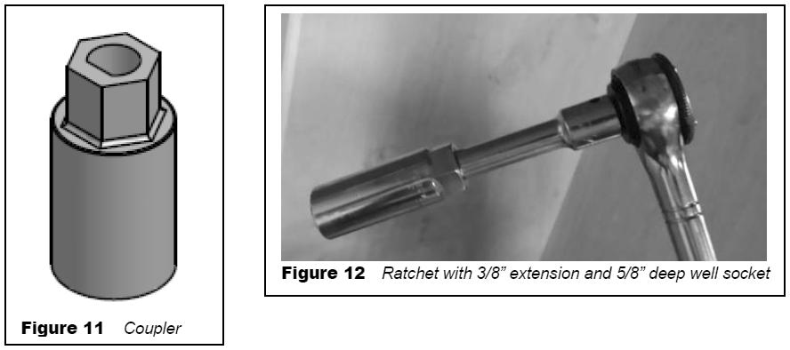

88 Section 5: Slideout Systems 78
89 Section 6: Electrical Systems The Electrical System The RV electrical system is comprised of two independent electrical systems. One operates off of 12-volt DC power and the other off of 120-volt 60hz AC power. All installations have been made in compliance with industry standards applicable on the date of manufacture. Because the electrical equipment and associated circuitry are engineered into a dedicated system specific to your RV, do not make unauthorized changes or add fixed appliances to it. Changes or additions made after delivery may result in a hazardous condition. Service and/or modification of the electrical system should only be performed by qualified electrical technicians using approved materials, components, and methods meeting current safety and code requirements. Consult your dealer s service department for assistance. To read more about the various components incorporated into the RV electrical system, please refer to the information contained in your Warranty Packet. Electrical System Maintenance Before working on the electrical system; always disconnect the shore power cord, turn off the battery disconnect switch (if so equipped) and turn off the 120V main circuit breaker. Then disconnect the negative 12VDC battery terminal from the battery. Refer to Battery Disconnect Switch & Load Center sections. Use caution when using metal tools. If a tool contacts a battery terminal or metal connected to it, a short circuit could occur which could cause personal injury, explosion or fire. In Case Of An Electrical Fire Do not attempt to use water to put out an electrical fire. Water can spread some types of fire, and electrocution is possible with an electrical fire. HAVE EVERYONE EVACUATE THE RECREATION VEHICLE IMMEDIATELY. Switch the 120-volt main circuit breaker to the off position. It is important that everyone knows where to find the main circuit breaker and how it operates. Disconnect the negative battery cable(s) at the battery. Disconnect the power cord from the shore power receptacle. Turn off the generator (if so equipped). Always have faulty or damaged wiring and electrical components repaired immediately. 79

 on/off switch.")
90 Section 6: Electrical Systems Command Center The command center is typically located inside the entrance door or in the living area of the RV, and contains switches and controls for various electrical functions. Command center applications, configurations and components will vary by model. Command Center Panel or Command Center Panel with Switch Modules Items found on these panels may include: Fuel gauge and hour meter with switches for fuel pump and fuel levels; fuel station (if so equipped) on/off switch. Lighted red pump and water heater switches (electric & LP gas) Generator start / stop switch; may include hour meter Tank heater switcheslight switches for porch lights, exterior security lights, interior lights, awning LED lights, front cap LED accent lights, power entry step Cargo bed red lighted control switch Slideout control switches (press and hold to extend / retract) Awning control switches (press and hold to extend / retract) Systems monitor with LED indicators for tank levels and battery charge status Auto leveling control panel (for leveling the RV) Inverter panel (power switch with display) Power bunk bed lift control switch Speaker selector switch Command Center Modules Mounted to the Wall Some models may have the modules mounted directly to the interior wall of the vehicle. They are typically located near the entrance door. Command Center Panel Command Center Panel W/Switch Modules GFCI Receptacle There is a ground fault current interrupter (GFCI) engineered into the electrical system. It is designed to reduce the possible injury caused by electric shock. The GFCI will not protect against short circuits or circuit overloads. Test all GFCI receptacles monthly Push in the GFCI TEST button. The GFCI RESET button should pop out indicating the GFCI receptacle has been tripped and interrupted 120-volt power. Push in the GFCI RESET button to restore 120-volt power. Contact your independent dealer for assistance if the GFCI RESET button does not restore 120-volt power and pops back out. A tripped GFCI breaker indicates that abnormally high 120-volt current flow (a ground fault) was detected. A fault condition can be caused by faulty wire insulation, wet wiring inside an appliance, faulty electrical equipment connected to the circuit, etc. All ground faults must be repaired before use of the recreation vehicle. 80
91 Section 6: Electrical Systems Testing the Campsite Power Connection The campsite 120-volt power receptacle(s) should always be tested for proper functionality prior to plugging the recreation vehicle shore power cord into it. Campsite 120-volt power receptacles can be tested using a digital multimeter or a dedicated circuit analyzer. Dedicated circuit analyzers plug directly into the campsite power receptacle and minimally test for open neutral, open ground, and correct polarity. Polarity indicators can be purchased in most electrical and hardware stores. Do not hook up the power cord to any receptacle until you have verified proper polarity and grounding. DO NOT plug the shore power cord into a campsite receptacle(s): That has reverse polarity With non-functioning ground circuits That shows outward signs of heat damage. Doing so may result in property damage or serious injury. Damage or injury resulting from connection to malfunctioning or improperly wired power sources is not covered by your recreation vehicle warranty. DO NOT Do not use any cheater plug, adapter or extension cord to reconfigure incoming AC power or break the continuity of the circuit connected to the grounding pin. Do not connect the power cord into an outlet that is not grounded, or adapt the power cord plug to connect it to a receptacle for which it is not designed. Do not remove the grounding pin to connect to a non-grounded receptacle. Removal of the ground pin disables an important safety feature designed to prevent shock and electrocution hazards. Do not connect the power cord to an extension cord. Use of an improper extension cord will cause overheating of the cord as well as potentially causing premature failure of the AC equipment. It is the responsibility of the owner of the electrical receptacle to ensure that the receptacle is properly wired and grounded. Reverse polarity and/or improper grounding of your RV can cause property damage or serious personal injury. 81
92 Section 6: Electrical Systems Connecting the Power Cord Plugging the shoreline power cord into an incorrectly wired power source could damage the recreation vehicle electrical system and result in severe or fatal injury. Always test the external power source (i.e., the campsite power receptacle or electrical box) with a ground monitor before connecting your power cord to it. If the ground monitor indicates reverse polarity or an open ground DO NOT connect the power cord. To help prevent power surges from damaging the connected loads, please follow these instructions when hooking up to the external power source: 1. Turn off the load center main 120-volt circuit breaker. 2. Carefully extend the entire length of the power cord (approximately ) from the electric cable hatch to the external power source. 3. Plug the power cord into the receptacle. Be sure all the power cord prongs are properly plugged into the receptacle. 4. Return to your RV and turn on the load center main circuit breaker. The shore line power cord should be unplugged when the recreation vehicle is left unattended. If something would happen to the electrical system, this may help limit potential damage. When you are ready to leave, reverse the power cord connection process. Use care to prevent damaging the power cord electrical connection pins when connecting or disconnecting the shore line power cord. Grasp the plug to remove the power cord from the outlet; do not unplug it by pulling on the cord. Maintenance Inspect the power cord for cuts, cracks and worn insulation. Have the power cord replaced immediately if these symptoms are noticed. The power cord must be fully extended when in use and not left coiled in the electrical compartment or on the ground. If the power cord is left coiled, it may potentially create enough heat to melt its protective casing. Power Converter The power converter converts 120-volt AC power to useable 12-volt DC power when the shore power cord is connected to an external power source. The converter has a built-in protective thermal breaker that will shut it down should overheating occur. Overheating can be caused by operating the converter above its maximum power output for an extended period of time, or by an obstruction to its ventilation air flow. To reduce converter heat build keep unnecessary 12-volt lights and motors turned off. Keep the converters cooling fins and fan clear of obstructions. USE ONLY A DEEP CYCLE BATTERY FOR RV USE. Car batteries (CCA rating) are not designed for RV applications. If doing a lot of dry camping use a 82
93 Section 6: Electrical Systems deep cycle battery rated in amp hours only (NO CCA rating). If using multiple batteries they must be the same brand and type. Adding more batteries will provide longer use of DC appliances when not on shore power but may reduce charging efficiency. The battery works in conjunction with the converter to supply DC power to the RV. A battery is typically only necessary if you do a lot of dry camping or have slideouts and/or a leveling system. Reverse polarity fuse provides protection for the converter when a battery is used. If the battery is connected backwards to the fuse board this fuse would blow preventing damage to the converter. If your lights are dimming or flickering that usually indicates an overloaded converter. Remove some of the load by turning off DC lights or appliances. Fan is controlled by load. It will begin running at 3 to 6 amp DC draw. It increases in speed with a higher load until 14 to 15 amps. Fan is at maximum speed and stays there even with more load. If load drops below 6 amps DC, the fan shuts off. Before checking for converter output voltage, the battery cables must be disconnected at the battery. Make sure the converter is plugged into an AC source ( AC volts). Check the converter output voltage at the battery with a voltmeter. Place the voltmeter probes on the disconnected battery cables. If the voltage reads 13.6VDC with no load, the converter is functioning properly. If the converter output voltage at the battery reads in the 0.0VDC range, or the battery is not charging, check for: An open inline fuse in the battery wire An open wire between the converter and the RV battery Loose ground connection Improper torques If the converter fuses and AC voltage are good, but the converter output still reads zero volts, the converter is not functioning properly. Modes of Operation: Absorption (Normal) Mode: 13.6VDC range. Batteries are being charged, just at a slower rate. Converter will not work without AC input Float Trickle Mode: To get your converter into this mode reduce the load on the system to almost nothing but the battery. Let the system sit for approximately 44 hours. Converter voltage will drop to 13.2VDC. If the converter sees any load during this period or after it is in Float Mode it will revert back to Absorption (Normal) Mode. 13.6VDC. Bulk Mode: Converter will not jump into the Bulk Mode unless the battery is below 50% of charge, or approximately below 13.2VDC output voltage. There is no way to force it to go into Bulk Mode. Red LED indicates blown fuse. Inspection and maintenance If the 12-volt power converter is not working (auxiliary battery not being charged) check the reverse polarity fuse(s) located on the end of the converter. There are no customer serviceable parts inside the converter case and the manufacturer s warranty will be void if the case has been removed. If you have further concerns contact 83
 Some converters may be equipped with a charge wizard There are (3) possible charging modes; NORMAL, BOOST and STORAGE.")
94 Section 6: Electrical Systems your dealer. For detailed information on operation and safety, refer to the manufacturer s owner s manual. Converter w/charge wizard (if so equipped) Some converters may be equipped with a charge wizard There are (3) possible charging modes; NORMAL, BOOST and STORAGE. The charge wizard will automatically select the best mode to charge your battery. A green LED next to the wizard mode button will indicate by flashes, which mode is currently being used. NORMAL MODE: Green LED flashes once per second; battery is between 50% and 90% charged. Green LED will flash 2-3 times per second; battery is 90% charged. Output voltage is 13.6VDC and the converter is safely completing the charge of the battery. BOOST MODE: Green LED is on solid. Output voltage is 14.4VDC to rapidly charge the battery up to 90% of full charge. STORAGE MODE: Green LED flashes every 6-8 seconds. Output voltage has been reduced to 13.2VDC; the RV battery is fully charged and converter is maintaining the charge. MANUAL MODE (Not recommended): The wizard mode button is used to override the charge wizard. Refer to the converter owner s manual for additional information. REVERSE BATTERY PROTECTION: Reverse polarity fuse(s) provide protection for the converter when a battery is used. If the battery is connected backwards to the fuse board a fuse will blow preventing damage to the converter. Four easily accessible fuses are located next to the wizard button. Replace with fuses of the same type and rating. 12-volt DC System The majority of your recreation vehicle lighting is powered by 12-volt electricity. The 12- volt DC system is composed of components that will operate when the following conditions are met: Power is supplied by the tow vehicle alternator when the engine is running and the 7-way trailer plug is connected. This powers the RV s running lights, brake lights, turn signals and brakes. In addition, the 7-way trailer plug provides a common ground and a 12-volt charge line to charge the auxiliary battery. The converter will supply interior 12-volt DC power when the power cord is plugged into campground power. The converter will also charge the RV battery in most situations. (Refer to Battery Disconnect) The auxiliary battery powers many interior 12-volt components including the lighting fixtures, water pump, 12-volt motors, 12-volt appliances, etc. It also powers the breakaway switch. 12-volt Fuse Panel The 12-volt fuse panel is labeled to indicate fuse sizes, positions and the components powered. At the beginning of camping season, inspect all the 12-volt fuses and replace as needed. Fuses are located in the load center. 84
95 Section 6: Electrical Systems Replacing a fuse Before replacing a fuse, always turn off the electrical components protected by it. 1. Disconnect the shore power cord. 2. Turn off the inverter (if so equipped). 3. Disconnect the house or auxiliary batteries main negative battery cable. 4. Remove the fuse panel cover to check fuses. 5. Pull the fuse straight out of the fuse block. If the fuse is not blown, something else must be causing the problem. Please contact your dealer for further assistance. 6. Insert a new fuse of the same specified voltage, amperage rating and type in the original location. Never use a higher rated replacement fuse. The fuse panel label should be kept permanently affixed to your recreation vehicle. Fuses will not offer complete protection of the electrical system in the event of a power surge or spike. Replacement fuses must be of the same voltage, amperage rating and type. Never use a higher rated replacement fuse; doing so may cause a fire by overheating the RV wiring. 12-Volt DC Outlet There may be one or more 12-volt DC power outlets in your recreation vehicle. When the 12-volt DC outlet is used as a power source for an electric appliance, make sure the appliance operates on 12-volt DC power and that it consumes less than 60 watts (5 amps) of power. Keep the protective dust cap on the 12-volt DC outlet when not in use to prevent ingestion of foreign material and potential short circuit conditions. 85
96 Section 6: Electrical Systems Auxiliary Battery (Customer Supplied) Do not store anything inside the battery compartment(s) or near the batteries that could touch the battery or battery cable terminals. Contact with the battery or battery cable terminals could cause an electrical short circuit, discharge the batteries, or start an electrical fire. Keep sparks, cigarettes and flames away from the batteries as the hydrogen gas they create may explode. Do not connect a booster battery or other power source that outputs more than 14.2-volts DC to the motor home batteries. Use adequate ventilation when charging or using batteries in an enclosed space. Remove metal jewelry and always wear eye protection when working around batteries. Do not allow battery electrolyte (acid) to come into contact with skin, eyes, fabric or painted surfaces. Electrolyte is a sulfuric acid solution that could cause serious personal injury or property damage. If your hands, eyes, clothes or the painted surface of your motor home are exposed to electrolyte, flush the exposed area thoroughly with water. If electrolyte gets in your eyes, immediately flush them thoroughly with water and get prompt medical attention. The combined 12-volt DC loads in your recreation vehicle become more than the converter can produce. This demand can be met by using an auxiliary battery for a limited period of time. The 12-volt system is designed for usage with a Group 27, deep cycle battery. Dry camping The auxiliary battery should be fully charged prior to dry camping. If the auxiliary battery is not being recharged and power is being drawn from it, it will eventually discharge. A battery will discharge at a faster rate as its energy level becomes depleted. Plan your electrical usage accordingly. You can test the auxiliary battery voltage using a volt-ohm meter (customer supplied). A fully charged auxiliary battery will read 12.7 volts DC and specific gravity at 80 F (32 C). The auxiliary battery is considered discharged at volts, and dead at volts. If the voltage drops below those levels, irreversible damage can occur. Typically, a deep cycle battery has an amp-hour rating of amps. If you run the furnace and refrigerator simultaneously, you will be using approximately ( ) 15.0 amps per hour. This does not include any 12-volt lights, or any other 12- volt component. If the furnace and refrigerator in this example operated constantly, a 75 amp-hour battery would become fully discharged in 5 hours (75ah / 15a = 5h). The auxiliary battery should be installed in parallel with the battery in your tow vehicle. When the 7-way trailer plug is connected, both batteries power the RV. Do not allow it to discharge your tow vehicle battery below the level required to start the engine. To prevent this from occurring, disconnect the 7-way trailer plug or install a battery isolator. When the tow vehicle engine is operating with the RV connected, the tow vehicle charging system will charge both batteries. 86


97 Section 6: Electrical Systems Replacement and maintenance Some equipment in your RV will draw small amounts of current even when turned OFF. To prevent the auxiliary battery from being discharged when your RV is not connected to shore line power, disconnect the auxiliary battery negative cable at the battery. During storage, it is important to check the voltage monthly and recharge the auxiliary battery as needed. If you remove the auxiliary battery from your RV, store it in a dry, cool area per the manufacturer s instructions. When it is time to replace the auxiliary battery, replace it with a Group 27 deep cycle battery only. Do not reverse the positive and negative battery cables (doing so will blow the reverse polarity fuse(s) that protect the converter). For more information Please contact the battery manufacturer for additional information on the auxiliary batteries. Battery Isolator For Your Tow Vehicle (Customer Supplied) You may want to consider the installation of a battery isolator on your tow vehicle as a convenience feature: It receives current from the tow vehicle alternator and controls distribution of energy to both the RV auxiliary battery and the tow vehicle battery. It serves as a check valve to prevent energy from being drawn from your tow vehicle chassis battery (so you can start your tow vehicle engine). Your dealer can assist you with the selection, purchase and installation of this aftermarket part. Battery Disconnect Switch (If So Equipped) The Battery Disconnect switch is typically located in an enclosed exterior compartment. The style of the disconnect switch may vary per model. The disconnect switch does not shut off all power, but only shuts off the 12VDC power to the main 12V fuse panel, and the interior of the vehicle. Batteries can still be trickle charged by the converter, and there will still be power to the landing legs on fifth wheels and certain other devices. Rotating Dial Disconnect Switch When this switch is ON, there will be a green area showing a 1 along the top of the switch. To turn the switch OFF, turn it counter-clockwise until you see the red area along the left side of the switch showing a 0 (zero). Lever Type Disconnect Switch To operate this switch, turn the lever counter-clockwise to turn off all 12VDC power to the fuse panel in the RV. The lever can be removed and is equipped with a lanyard to keep the key from getting lost. Battery Disconnect Switches Switch appearance may vary by model 87

98 Section 6: Electrical Systems Load Center The Load Center contains 12VDC fuses and 120VAC circuit breakers for almost all of the electrical appliances and circuits in the RV. The 120V main breaker may be located in this panel and will turn off all 120-volt power to the RV. The load center is typically attached to a cabinet face in the main living area. Locations will vary by model. Refer to the diagram inside the load center for specific fuse assignments. Not all load centers will include a main breaker. Typical Load Center Panel Approximate Electrical Load Ratings 12 Volt System Exterior Entertainment Center Fan Furnace Generator Start Illuminated Switch Inverter Leveling System LP Detector Light; Halogen Light; Vanity Lights; Aisle Lights; Baggage Compartment / Shower Lights; Decorative Wall / Map / Porch Lights; Fluorescent Double -12 Lights; Fluorescent Double -18 Power Awning Power Vent Refrigerator Step Cover TV Plate/Antenna Booster Water Heater Load Center Panel w/120 volt Main breaker Load center appearance and configuration may vary by model 5-7 AMPS 1.5 AMPS 12.0 AMPS 95.0 AMPS*.125 AMP variable 95.0 AMPS*.125 AMP 1.7 AMPS 4.2 AMPS 1.0 AMP 1.4 AMPS 1.5 AMPS 2.0 AMPS 2.5 AMPS 10.0 AMPS 5.0 AMPS 3.0 AMPS 10.0 AMPS 1.0 AMP 6.0 AMPS Water Pump 7.0 AMPS *Momentary Load 12 Volts: Labeled watts divided by 12 = Power consumed in AMPS 88
99 Section 6: Electrical Systems Air Conditioner Coffee Maker Converter (each) DVD System Fireplace Hair Dryer or Curling Iron Microwave Refrigerator Satellite Receiver TV Vacuum Cleaner Washer/Dryer Water Heater 120 Volt System 18 AMPS 6-12 AMPS 8 AMPS 3 AMPS 12 AMPS AMPS 12 AMPS 6 AMPS 2 AMPS 2-4 AMPS 8 AMPS 12 AMPS 12 AMPS 120 Volts: Labeled watts divided by 120 = Power consumed in AMPS 120-volt (30 AMP) AC System (If So Equipped) The 30 amp 120-volt 60hz AC electrical system.is designed to operate on 1 leg of 120-volt power at a maximum current flow of 30 amperes. Exposure to voltages higher or lower than a nominal 120-volts will damage or shorten the service life of the electrical system and appliances. The 30 amp 120-volt 60hz AC electrical system can be powered by the 120-volt 60hz utilities found in RV campgrounds or by 120- volt 60hz generator power. The following electrical components will only operate when your recreation vehicle is connected to shore or generator power: 120 to 12-volt power converter, air conditioner, refrigerator, microwave oven, television(s), home theater system(s), electric water heater, washer, dryer, fireplace, and appliances plugged into convenience receptacles. Make certain the external power source you connect the power cord to is a properly wired 30 amp NEMA TT-30 RV receptacle and not 240 volt AC. Circuit breakers and fuses will not offer complete protection of the electrical system in the event of power surge or voltage spike. 30-amp Power Cord (If So Equipped) PLUG INTO 30-AMP SERVICE ONLY. The 30 amp external utility power cord is commonly referred to as the shore power cord. It 89
100 Section 6: Electrical Systems is designed to mate and properly function with 30 amp shore power receptacles available at most campgrounds. The shore power cord is designed to continuously carry the 30 amp current flow required to power each leg of the electrical system. It also creates a critical ground connection between the vehicle electrical system and the campground shore power receptacle. Calculating 30 AMP Electrical Load (If So Equipped) When connecting appliances to the electrical system, 120-volt power usage is limited to a total of 30 amps. Operating appliances collectively places an added load on your 120-volt electrical system. An unintentional trip of a circuit breaker may occur if you overload the recreation vehicle and/or campground electrical system. The amperage rating of individual appliances can be calculated by dividing appliance wattage consumed (normally listed on the appliance) by nominal design voltage (120 for a 120-volt appliance). For example: 1200 watts divided by 120-volts equals 10 amps. Only connect the shore power cord to properly wired 30 amp NEMA TT volt power receptacles. 120-volt (50 AMP) AC System (If So Equipped) The 50 amp 120-volt 60hz AC electrical system can be powered by an outside 120/240-volt 60hz utility service like those commonly found in campgrounds or by 120/240-volt 60hz generator power. The entire system is designed to operate on 2 legs of 120-volt power at a maximum current flow of 50 amperes per leg. Exposure to voltages higher or lower than a nominal 120-volts, will damage or shorten the service life of the electrical system and appliances. The 50 amp 120-volt 60hz AC electrical system can be powered by an outside 120/240-volt 60hz utility service like those commonly found in campgrounds or by 120/240-volt 60hz generator power. The following electrical components will only operate when connected to 120-volt power: air conditioner(s), refrigerator, microwave oven, television(s), home theater system(s), water heater, washer, dryer, fireplace, electric stove, and appliances plugged into convenience receptacles. Circuit breakers and fuses will not offer complete protection of the electrical system in the event of power surge or voltage spike. Make certain the external power source you connect the power cord to is a properly wired 50 amp NEMA RV receptacle and not 240 volt AC. 90
101 Section 6: Electrical Systems Do not hook up the power cord to any receptacle until you have verified proper polarity and grounding. Polarity indicators can be purchased in most electrical and hardware stores. Do not use any cheater plug, adapter or extension cord to reconfigure incoming AC power or break the continuity of the circuit connected to the grounding pin. Do not connect the power cord into an outlet that is not grounded, or adapt the power cord plug to connect it to a receptacle for which it is not designed. Do not remove the grounding pin to connect to a non-grounded receptacle. Removal of the ground pin disables an important safety feature designed to prevent shock and electrocution hazards. Do not connect the power cord to an extension cord. Use of an improper extension cord will cause overheating of the cord as well as potentially causing premature failure of the AC equipment. It is the responsibility of the owner of the electrical receptacle to ensure that the receptacle is properly wired and grounded. Reverse polarity and/or improper grounding of your recreation vehicle can cause personal injury or death. 50-amp Power Cord (If So Equipped) PLUG INTO 30-AMP SERVICE ONLY. The 50 amp external utility power cord is commonly referred to as the shore power cord. It is designed to mate and properly function with 50 amp shore power receptacles available at most campgrounds. The shore power cord is designed to continuously carry the 50 amp current flow required to power each leg of the electrical system. It also creates a critical ground connection between the vehicle electrical system and the campground shore power receptacle. Calculating 50 AMP Electrical Load (If So Equipped) When connecting appliances to the electrical system, remember that 120-volt power usage is limited to 50 amps per electrical system leg for a total of 100 amps. Each operating appliance collectively places an added load on your 120-volt electrical system. An unintentional trip of a circuit breaker may occur if you overload the recreation vehicle and/or campground electrical system. The amperage rating of individual appliances can be calculated by dividing appliance wattage consumed (normally listed on the appliance) by nominal design voltage (120 for a 120-volt appliance). For example: 1200 watts divided by 120-volts equals 10 amps. Only connect the shore power cord to RV 50 amp 120/240 volt electrical power receptacles. 91
102 Section 6: Electrical Systems Do not hook up the power cord to any receptacle until you have verified proper polarity and grounding. Polarity indicators can be purchased in most electrical and hardware stores. Do not use any cheater plug, adapter or extension cord to reconfigure incoming AC power or break the continuity of the circuit connected to the grounding pin. Do not connect the power cord into an outlet that is not grounded, or adapt the power cord plug to connect it to a receptacle for which it is not designed. Do not remove the grounding pin to connect to a non-grounded receptacle. Removal of the ground pin disables an important safety feature designed to prevent shock and electrocution hazards. Do not connect the power cord to an extension cord. Use of an improper extension cord will cause overheating of the cord as well as potentially causing premature failure of the AC equipment. It is the responsibility of the owner of the electrical receptacle to ensure that the receptacle is properly wired and grounded. Reverse polarity and/or improper grounding of your recreation vehicle can cause personal injury or death. 120-volt Circuit Breakers The 120-volt AC circuit breakers located inside the load center protect all 120-volt wiring and components from circuit overloads and short circuits. Should a circuit overload or short circuit occur the circuit breaker protecting the affected circuit will trip preventing the flow of electricity through that circuit. If a circuit breaker trips, shut off the appliance on that circuit (i.e., power converter etc.) and allow the circuit breaker to cool down for a brief period of time. After it cools down, reset the circuit breaker by moving its lever off and then back to the on position. If the circuit breaker re-trips or frequently trips, contact your dealer to have the electrical problem diagnosed and repaired. A circuit breaker identification label is permanently attached to the inside surface of the 120- volt Load Center. 120-volt circuit breakers are located in the sub-panels inside the cabinet above the driver seat. NOTE: Load Centers may not always include a main circuit breaker.+ Circuit breakers and fuses will not offer complete protection of the electrical system in the event of power surge or voltage spike. 92
103 Section 6: Electrical Systems Replacement Only replace circuit breakers with those of the same specified type, voltage, and current rating. Never replace a circuit breaker with one listed at a higher amperage rating. Please contact your dealer for repair assistance when replacing circuit breakers. Replacement circuit breakers must be of the same voltage, amperage rating and type. Never use a higher rated replacement circuit breaker; doing so may cause a fire by overheating the RV wiring. Maintenance At the beginning of camping season, inspect the circuit breakers and replace as needed. Test by turning each circuit breaker off and back on. Circuit breakers are wearable parts and must be replaced as needed, as part of your RV maintenance. If you have any questions, consult your dealer. A label is provided to explain the function of every 120-volt circuit breaker. This label is located on or near the appropriate load center or sub-panel and must remain permanently affixed to the recreation vehicle. Solar Prep (If So Equipped) Your recreation vehicle may be wired with a (exterior) plug in that will allow the batteries to be trickle charged using a free standing solar panel. In most models, the solar panel kit is a customer purchased and installed option. The solar plug location will vary by model, but may be located either on the sidewall, on the A-frame of the vehicle or in the outside utility center. There are capped off wires located in the area of the battery. These wires are the battery charging wires. Once these wires are properly connected to your battery, you will then be able to plug the solar panel into the charging port. When the system is connected properly, the solar panel will supply power to the battery, the battery will supply power to the converter, and the converter will supply power to all the 12V systems as needed. Solar Plug Replacing Light Bulbs Before replacing a bulb, be sure the light is off. Do not touch the glass part of the new bulb with your bare fingers. The skin oil left on the glass will evaporate when the bulb gets hot, the vapor will condense on the reflector and it will dim the surface. Replacement light bulbs must be of the type, voltage and wattage listed on the lamp fixture. Use of incorrectly sized bulbs can overload lam circuits and may create a fire hazard by overheating the fixture. 93
104 Section 6: Electrical Systems Notes: 94
105 Section 7: Fuel & Propane System Exhaust Gas Fumes Avoid inhaling exhaust gases as they contain carbon monoxide, which is a potentially toxic gas that is colorless and odorless. If you are in a recreation vehicle with either a nearby tow vehicle engine running or the generator (if so equipped) running there is a potential for exhaust fumes to filter back into the recreation vehicle. To avoid breathing exhaust gases, follow these precautions: Always shut OFF the tow vehicle engine, generator engine (if applicable), etc., while refueling. Do not run the tow vehicle engine, generator engine (if applicable), etc., in confined areas, such as a closed garage, any longer than needed to move your RV in or out of the area. Windows should be closed while driving or running the generator (if so equipped) to avoid drawing dangerous exhaust gases into the RV. If you suspect that exhaust fumes are entering the RV have the cause determined and corrected as soon as possible. The best protection against carbon monoxide entry into the RV is a properly maintained ventilation system and an active carbon monoxide detector. To allow for proper operation of the RV ventilation system, keep the ventilation inlet grill(s) clear of snow, leaves or other obstructions at all times. See the Occupant Safety section of this manual for additional information on carbon monoxide safety. Propane Gas System Propane or LP (liquefied petroleum) gas is an efficient form of energy when proper handling and safety precautions are observed. The propane system in your recreation vehicle furnishes the fuel for cooking, heating, hot water and can be an alternative energy source for refrigeration Propane is heavier than air; and tends to flow to lower areas and will sometimes pocket in these low areas, such as the floor. Your recreation vehicle is equipped with a propane alarm (refer to the Safety Precaution sections, Combination Carbon Monoxide (CO)/Propane Alarm.) The propane fuel system is comprised of numerous components such as the propane container, hoses, the propane gas regulator, piping and copper tubing to each appliance. Although your recreation vehicle has been carefully tested at the factory, and by your selling Propane cylinders should not be placed or stored inside RV. LP-gas cylinders are equipped with safety devices that relieve pressure by discharging gas into the atmosphere. 95

106 Section 7: Fuel & Propane System dealer for leakage, travel vibrations can loosen fittings. Have the propane system checked at all connections soon after the purchase of your recreation vehicle, and after the initial filling of the propane tanks. Continued periodic checks of the propane system at 5,000 miles of travel (or at least once a year), by a qualified propane service representative as part of your normal maintenance is recommended. Hand tighten the LP gas system valves only, do not use a wrench or pliers as over tightening may damage the valve seals and cause them to leak. NOTE: All propane lines have been checked with air pressure at the time of manufacture. Dealers are required to recheck and adjust pressure before retail delivery. Propane Leak Test Leaks may be found easily with a soapy water solution. Do not use a solution containing ammonia or chlorine when locating leaks. These products are corrosive to copper gas lines and brass fittings, which could result in deterioration of the copper and brass components. Apply the soapy solution to the outside of the gas piping fittings. If a leak is present, the soapy solution will bubble at the leak point. If a leak is indicated, shut off the propane system valve(s) and contact your dealer or qualified propane service representative immediately. Never use an open flame to test for a propane leak. Do not check for leaks using products that contain ammonia or chlorine; these products can cause cracks to form on the metal tubing and brass fittings Propane Safety Procedure Propane is a colorless and odorless gas that, in the liquefied state, resembles water. An odorant (usually a sulfur compound) is added as a warning agent. If you smell propane within the vehicle, quickly and carefully perform the procedure listed on the propane system label. This label has been placed in the vehicle near the range, for models equipped with a propane systemwhen propane container is low, occasionally there may be a concentration of an onion or garlic-like odor, which can be mistaken for a propane gas leak. After the propane container has been refueled, the odor will usually disappear. If not, turn off the valve(s) and have the propane system inspected by your dealer or qualified propane service representative. Propane system label 96
107 Section 7: Fuel & Propane System Propane Gas Container Propane container is a general all inclusive term used to describe a vessel that is used for storage and delivery of propane gas. The most common of these are: DOT (Department of Transportation) cylinders are transportable and are commonly used on recreation vehicles. The capacity of DOT propane cylinders is expressed in pounds. DOT propane cylinders are required to be removed from the RV for filling and must be filled by weight by a qualified propane facility. DOT Propane cylinders are equipped with an OPD (over fill protection device) designed to reduce the potential of overfilling. DOT propane cylinders are also equipped with an ACME service valve that is for connection of the TYPE 1 ACME pigtail hose assembly to the RV two-stage regulator. The TYPE 1 ACME pigtail hose assembly is a wrenchless, right hand threaded connector that features a thermally sensitive sleeve and excess flow device. Max output is 200,000 BTU/hr. It is used to connect propane cylinders to regulators, hoses and other fittings. It is not for use on gas grills and other low pressure devices. DOT cylinders equipped with an OPD and ACME type 1 service valve are identified by the triangular service valve knob. DOT cylinders are typically marked with top or an arrow to indicate the correct orientation of the cylinder(s). Do not mount, store or transport any cylinder other than the in proper position indicated. Be sure to securely re-install DOT cylinder(s) to the recreation vehicle after they have been removed for filling or replacement. Always close the service valve and install a dust cap or plug when transporting or storing disconnected containers whether full or empty. ASME tanks are permanently mounted to the RV and are commonly used on RV motor homes. The capacity of ASME tanks is expressed in gallons. ASME tanks are filled while the tank is tank is attached to the motor home by a qualified propane facility. ASME tanks are equipped with an automatic stop fill valve designed to reduce the potential of overfilling. ASME propane tanks are also equipped with a P.O.L. service valve that is for connection of the supply hose with a left hand threaded brass P.O.L. fitting from the tank service valve to the two-stage regulator. Not for use on gas grills and other low pressure devices. DOT propane cylinders must be transported and stored in an upright position so the pressure relief device will function properly. Laying a DOT propane cylinder on its side may potentially create a very dangerous situation. NOTE: Tanks are to be installed, fueled and maintained in accordance to State and Local codes, rules, regulations or laws. Propane is a true gas compressed into a liquid form. As the fuel is released from the container, it changes to vapor which is then used for the operation of the appliances. Propane will not run through the appliances in the liquid state. 97


108 Section 7: Fuel & Propane System Propane expands 1½ percent for every ten degrees of increase in temperature. It is imperative to leave sufficient space inside the container to allow for natural expansion of gas during warmer weather. The main shut off valve must be kept closed at all times unless you are using the propane system or filling the propane cylinder. When the cylinder is disconnected from the hose, install the valve cover that is attached to the container. Close the propane cylinder main shut off valve by hand tightening only. Use of tools creates a potential to over tighten the valve (damaging the interior seals on the cylinder valve seat). If this type of damage occurs, the cylinder will not close properly. This propane label should be kept permanently affixed to your RV. Servicing or filling Have the recreation vehicle checked for leaks at the connections on the propane system soon after the purchase and the initial filling of each propane cylinder. When you have a new cylinder filled for the first time, make sure your propane supplier purges your new Use propane only label (Canada only) cylinder of trapped air. Otherwise, an improper mixture of (Label appearance may not be exact) gas and air will make it impossible to light your propane appliances. Before entering a propane or fuel service station make sure all pilot lights are extinguished. Shut off gas to all appliances by closing the propane gas main shut off valve. Always shut OFF any engine before refueling. Do not smoke and do not operate other ignition sources while refueling No one should be inside and only the qualified propane service technician should be near the RV while the propane tank is being filled. The new propane container must be carefully purged for best performance and must NEVER BE OVERFILLED. This shut off for re-fueling label should be kept permanently affixed to your RV. The position of the propane container(s) and the hoses are critical to proper operation and propane flow. Follow these instructions to make sure your propane container(s) are connected properly. Shut off for re-fueling label (Label appearance may not be exact) The pigtale hose must be installed to avoid tension or pulling stress at either end of the hose. Keep the pigtail hose away from sharp edges of the cylinder collar, rigid corners, walls, doors or other compartment structures including the cover. 98


109 LP gas container overfill Section 7: Fuel & Propane System If you suspect your propane container has been overfilled, contact your independent Jayco dealer or a qualified propane technician for assistance immediately. Do not attempt to service a propane container overfill yourself. Never allow your propane tank to be filled above the maximum safe level as indicated by the fixed liquid level gauge. Do not allow the visible gauge to be used for filling. Overfilling the propane container above the liquid capacity indicated on the container, could allow liquid propane to enter the system that is designed for vapor only creating a hazardous condition. This label should be kept permanently affixed to your RV. Refer to your Warranty Packet for more information on the LP gas system components. Installing Propane Cylinder(s) Make sure all fasteners are secured before traveling. Do not fill to more than 80% label (Label appearance may not be exact) Single Cylinder Mounted On A-Frame (if so equipped) 1. Connect the 3/8 low pressure hose to the outlet of the two stage regulator. 2. Attach the regulator with the Z bracket on the center of the front wall with the vent pointing down. 3. Attach the protective plastic cover to the regulator. 4. The regulator has a 90 elbow that directs the inlet toward the trailer curbside. 5. Place the cylinder on the bracket provided on the A-frame and position it so the outlet of the cylinder valve is pointed directly outward to the curbside wall. 6. Attach the 1/4 inverted flare x 24 Type 1 pigtail hose to the regulator inlet and the right hand swivel nut to the cylinder valve. 7. Secure the cylinder to the A-frame bracket using the bolts, nuts and washers provided. Double Cylinder Mounted On A-Frame (if so equipped) Single Cylinder When a second cylinder is installed, a tee check valve is used to replace the 90 elbow at the top of the regulator and another 1/4 inverted flare x 24 Type 1 pigtail is added. The regulator stays in the original position. Place the second cylinder on the A-frame bracket so the cylinder valve is pointed to the roadside of the recreation vehicle. 99

110 Section 7: Fuel & Propane System 1. Secure the second cylinder to the A-frame using the bolts, nuts and washers provided. 2. Attach the second 24 hose to the tee check valve on the regulator and the right handed swivel nut to the cylinder valve. Maintenance Propane gas is normally non-corrosive - you need not worry about the inside of your container. However, the outside should be kept free from rust by a periodic coat of paint in a light reflective color. Rust, scratches and/ or dents can affect the safety of the cylinder. Inspect Double Cylinder the cylinder at regular intervals. If there is a problem, have it evaluated by a qualified technician and discard it. DOT requires that a visual inspection be made prior to each filling. Any cylinder that has been exposed to fire, leaks or seems damaged should not be refilled. Do not attempt to repair any containers, container valves, regulator or appliances by yourself. Use only trained certified propane gas service technicians to perform repairs. Propane cylinder recertification DOT cylinders may only be used for 12 years after their manufacture date (the number of years for certification may vary in your area). After that, the cylinders must be recertified which provides another five years of use. The cylinders can be recertified every five years thereafter. Federal DOT (Department of Transportation) regulations require periodic inspections and re-qualifications of the propane cylinders. DO NOT USE damaged or rusted containers. Verify with your local propane dealer that all required inspections and certifications have been completed on the propane cylinder within the correct time period before refilling the cylinder. Have the LP system checked for leakage each time a cylinder is refilled or after any part of the propane system has been disconnected. Hoses, Pipes, Tubes & Fittings The hoses, pipes, tubes and fittings used in your propane system are designed to withstand pressures exceeding those of the propane system. However, because environment and time can both contribute to the deterioration of these components, they must be inspected for wear at regular intervals. Be sure to inspect the hose before each season and when having the tank refilled. Look for signs of deterioration such as cracks or loss of flexibility. When replacing the hose or other propane components, make sure to always replace them with components of the same type and rating (check with your dealer). Fittings are used to connect the various system components to each other. The P.O.L. fitting at the end of the propane supply hose is made of brass so that pipe sealants are not necessary to prevent leaking. It also has a left-handed thread, which means that it is turned clockwise to remove, and counter-clockwise to tighten. The P.O.L. fitting has been designed to help restrict the flow of LP gas in the event of a regulator failure or hose malfunction. 100
111 Installing Propane Cylinder(s) Section 7: Fuel & Propane System Make sure all fasteners are secured before traveling. Located in a recessed compartment or housing (if so equipped) 1. Connect the 3/8 low-pressure hose to the outlet of the two-stage regulator. 2. Place the cylinder on the bracket in the recess compartment or housing and secure them so the outlets of the cylinder valves are facing the sidewalls of the compartment or housing (opposite of each other). 3. Mount the regulator on the center back wall of the compartment or housing so the vent is pointed downward. 4. Attach the 1/4 inverted flare x 18 Type-1 pigtail Two propane cylinders hose to the regulator inlet and the right hand swivel nut to the cylinder valve. Main Supply Hose Low Pressure Attach the main supply hose from the Main supply hose regulator to the brass manifold fitting in the frame of the trailer. The swivel brass nut on the main hose will be your final attachment. Each time the propane container is removed: 1. Check that ALL fittings are tight. 2. Check that ALL connections are tested with a propane leak detector (or soapy water) solution. 3. Open the main valve slowly to avoid a fast rush of propane to the excess flow valve causing propane freeze up. If you experience a propane freeze-up, close the main valve and wait at least fifteen (15) minutes before trying again. Refer to the regulator manufacturer s operator manual. 4. Listen carefully - a hissing sound longer than one second may indicate a propane leak. If you feel there may be a leak present, close the valve and contact your dealer or qualified propane technician for repair assistance. Replace all protective covers and caps on the propane system after filling. Make sure the valve is closed and the compartment door is securely latched. Maintenance Propane gas is normally non-corrosive - you need not worry about the inside of your container. However, the outside should be kept free from rust by a periodic coat of paint in a light reflective color. Rust, scratches and/or dents can affect the safety of the cylinder. Inspect the cylinder at regular intervals. If there is a problem, have it evaluated by a qualified technician and discard it. DOT requires that a visual inspection be made prior to each filling. 101
112 Section 7: Fuel & Propane System Any cylinder that has been exposed to fire, leaks or seems damaged should not be refilled. Do not attempt to repair any containers, container valves, regulator or appliances by yourself. Use only trained certified propane gas service technicians to perform repairs. Propane cylinder recertification DOT cylinders may only be used for 12 years after their manufacture date (the number of years for certification may vary in your area). After that, the cylinders must be recertified which provides another five years of use. The cylinders can be recertified every five years thereafter. Federal DOT (Department of Transportation) regulations require periodic inspections and re-qualifications of the propane cylinders. DO NOT USE damaged or rusted containers. Verify with your local propane dealer that all required inspections and certifications have been completed on the propane cylinder within the correct time period before refilling the cylinder. Have the LP system checked for leakage each time a cylinder is refilled or after any part of the propane system has been disconnected. Hoses, Pipes, Tubes & Fittings The hoses, pipes, tubes and fittings used in your propane system are designed to withstand pressures exceeding those of the propane system. However, because environment and time can both contribute to the deterioration of these components, they must be inspected for wear at regular intervals. Be sure to inspect the hose before each season and when having the tank refilled. Look for signs of deterioration such as cracks or loss of flexibility. When replacing the hose or other propane components, make sure to always replace them with components of the same type and rating (check with your dealer). Fittings are used to connect the various system components to each other. The P.O.L. fitting at the end of the propane supply hose is made of brass so that pipe sealants are not necessary to prevent leaking. It also has a left-handed thread, which means that it is turned clockwise to remove, and counter-clockwise to tighten. The P.O.L. fitting has been designed to help restrict the flow of LP gas in the event of a regulator failure or hose malfunction. Propane Regulator Propane regulators must always be installed with the regulator vent facing downward. Regulators that are not located in baggage compartments have been equipped with a protective cover. Make sure the regulator vent faces downward and (if applicable) the cover is in place to minimize vent blockage that could result in excessive gas pressure causing fire or explosion. Single stage regulator Some models are equipped with a single stage regulator. Two stage regulator The two-stage regulator has the only moving components in the propane system. Its sole 102
113 Using The Propane System Use the following steps for propane operation: Section 7: Fuel & Propane System function is to reduce the pressure from the propane containers to a safe and consistent low operating pressure. The first stage reduces the container pressure to lbs. The second stage reduces the lbs. of pressure further to an operating pressure of 11 W.C. (water column) or 6.35 oz. of outlet pressure to your appliances. The second stage is adjustable and will need to be adjusted by your dealer or qualified propane service technician for optimum performance (this adjustment should always be made with a properly calibrated manometer). If the pressure is too high, it affects performance and safety; if the pressure is too low, your appliances will not operate correctly. If your recreation vehicle is equipped with the automatic two-stage regulator, with both cylinders full of propane, turn the lever on the regulator towards the cylinder you wish to use first. This will now be the supply cylinder and the other the reserve. Slowly open both cylinder valves. The indicator on top of the regulator will turn bright green. When the cylinder becomes empty, the indicator will change to bright orange. Now turn the regulator lever to the side of the reserve cylinder and the green signal should return. You may now remove the empty cylinder to have it refilled without interrupting the flow from the full bottle. After filling the cylinder, connect the pigtail hose and slowly open the bottle valve. 1. Close ALL burner valves, controls and pilot light valves. 2. Open the main valve in the propane tank slowly to avoid a fast rush of propane vapor through the excess flow valve causing propane freeze-up. Should you experience propane freeze-up, close the main valve and wait 15 minutes before trying again. 3. Listen carefully as propane begins to flow. If a hissing noise is heard for more than one or two seconds, close the main valve and contact your recreation vehicle dealer to have the propane system tested. 4. Light the appliances as needed and directed in the appropriate appliance manufacturer s owner manual located in the Warranty Packet. Keep the propane container valves closed at all times unless you are using the propane gas system or are having the propane container filled. Make sure that you read and fully understand ALL safety requirements for handling and operation of the propane system. The propane system must be handled with care. If you have any questions or concerns, consult with your dealer and/or the specific appliance manufacturer. If you have double cylinders on your recreation vehicle, use only one at a time. Otherwise, the propane supply will be drawn equally from both cylinders until the supply has been totally exhausted. Using one cylinder until it is empty, then using the second cylinder will allow you to fill the empty cylinder at your convenience without running totally out of propane. Calculating Propane Gas Usage Most RV gas appliances are operated intermittently, and each has a different BTU rating. You will need to consider this when planning your propane supply and consumption. Unless there is heavy use of hot water, the water heater consumption of propane is minimal. During 103


114 Section 7: Fuel & Propane System cool temperature or high wind conditions, furnace consumption can be extremely high. To calculate your propane supply, take the BTU ratings for your propane appliances and divide that into the BTU availability. Each gallon of propane gas (3.785 liters) produces about 91,500 BTU s (96,528 kilojoules) of heat energy. Propane consumption chart The following chart provides average propane consumption information. Appliance Average BTU Consumption per Hour Kilojoules/Hour Water Heater 8,800 9,280 Refrigerator 1,200 1,500 1,270 1,580 Furnace 35,000 40,000 36,930 42,200 Range/oven 7,100 7,490 Range, rear burner 6,500 6,860 Range, front burner 9,000 9,490 Outside Grill 10,000 10,550 Cooking With Propane Gas Do not turn gas range burner controls to ON and allow gas to escape before lighting. Do not use portable fuel burning equipment (i.e., wood and charcoal grills or stoves) inside the recreation vehicle. Unlike homes, the amount of oxygen supply is limited due to the size of the recreation vehicle. Proper ventilation when using the cooking appliance(s) will help you avoid the danger of asphyxiation. It is especially important that cooking appliances not be used for comfort heating, as the danger of asphyxiation is greater when the appliance is used for long periods of time. FAILURE TO COMPLY MAY RESULT IN DEATH OR SERIOUS INJURY. Cooking / comfort heating label These warning labels are located in the cooking area to remind the user to provide an adequate supply of fresh air for combustion. Ensure a supply of fresh air (Canada units only) 104
115 Section 7: Fuel & Propane System Traveling with Propane Use care when fueling your tow vehicle. Make certain your propane container is properly fastened in place. Some states prohibit propane appliances to be operated during travel, especially in underground tunnels. Make sure you know the laws for the areas where you travel. This label should be kept permanently affixed to your recreation vehicle: Re-fueling Warning Label 105
116 Section 7: Fuel & Propane System Notes: 106
, water heater, tub/shower, and water purification system (if so equipped).")
117 There are two different water systems in your recreation vehicle: Section 8: Plumbing System The fresh water system consists of the fresh water holding tank, faucets and connections, water pump, outside shower assembly (if so equipped), water heater, tub/shower, and water purification system (if so equipped). The waste water system consists of the waste water and sewage holding tank(s), drains and toilet. Plumbing System Maintenance Check all fittings, pressure and waste, for leaks before each trip or before vehicle storage as part of your normal maintenance: Inspect all faucets, the water purification system (optional) and sink connections (including drain baskets or filters). Inspect connections at the water pump and water heater. At the end of every trip, you should drain any unused water from the fresh water system. All water contains contaminant and mineral particles that can cause fresh water system odors. Untreated well water is a major source of water system odors. The fresh water (or potable water) system needs periodic sanitization and winterization to take care of all the components within the plumbing system and help discourage the growth of bacteria and other organisms that can contaminate the water supply. Typically, there are labels affixed to the exterior of the recreation vehicle sidewall that indicate the locations of the water system drains and fills. Be aware some drain valves may be located inside the vehicle (once the exterior label is found, go inside to find the drain corresponding location). Monitor Panel Depending on your model, the monitor panel may be located on the Command Center panel, on an interior wall, or on the exterior utility center. It allows you to monitor the fresh water, grey water, black water and auxiliary battery levels. These functions are controlled using the monitor panel tact switches. The monitor panel operates on 12-volt DC power supplied by either the converter or auxiliary battery. No power is drawn from the battery unless a switch is pushed or turned ON. Fuses for the monitor panel are located in the load center. Refer to the manufacturer s operators manual for additional information. Monitor Panel NOTE: If your RV has secondary black or gray tanks, there may also be an additional tank monitor. located elsewhere in your RV. It is typically labeled as a convenience center. Operation Press only one tact switch at a time. As you push either the FRESH, BLK GREY1 or GREY2 switch, one or more LED lights will illuminate (from left to right) indicating the content 107
.")
118 Section 8: Plumbing System level for that tank. When pushing the BATT switch, the LED lights illuminate from left (lowest) to right (highest) to indicate the estimated auxiliary battery condition. NOTE:When using shore power all 4 LEDs will light. If disconnected from shore power, 3 LEDs will light to indicate a full charge (4th LED may blink). The LEDs corresponding to the letters C,G,F,L on the panel indicate the following: C = Charge at 12.7 volts G= Good at 12.1 volts F= Fair at 11.6 volts L = Low at 6.0 volts. Fresh Water System All water contains contaminant and mineral particles that can cause fresh water system odors. Untreated well water is a major source of water system odors. The fresh water (potable water) system needs periodic sanitization and winterization to take care of all the components in the plumbing system to discourage the growth of bacteria and other organisms that can contaminate the water supply. Command Center (Monitor panel appearance and components may vary) The water pump switch (if so equipped) may be located on the monitor panel, the utility center or both. When the water pump switch is ON (it will light up), the water pump will Never travel with full fresh, black or grey water holding tanks. DO NOT drink water deemed microbiologically unsafe or of unknown quality. Fresh Water Holding Tank There may be several ways to fill the fresh water tank depending on the model. For details of each method, refer to the Fresh Water Connections or the Utility Center (if so equipped) sections. There are plastic overflow tubes in the fresh water holding tank which allow water to flow out of the water tank (see City Water Fill). Occasionally, you may see water coming from the overflow tubes when the fresh water holding tank is filled. This is normal and can be a result of the recreation vehicle being parked on an incline, or the motion caused by starting or stopping during travel. 108

119 Section 8: Plumbing System Be careful not to overfill the fresh water holding tank. It can pressurize the tank, causing leakage and water damage and void the warranty. DO NOT leave the tank unattended while filling. Do not cap, block or modify the fresh water tank overflow tubes in any way. Enough water pressure can build up during the filling process to damage the plumbing system if the overflow tubes are obstructed. 12-Volt Water Pump & Switch When you want to use water in your recreation vehicle and it is not hooked up to city water, you will need sufficient 12- volt DC power to run the water pump. Once activated, the water (demand) pump will self-prime, and provide water. The pump is designed for intermittent use only. Using the pump continuously or with high pressure will shorten the life of the pump and is not covered in your warranty. The water pump is engineered with a check valve to prevent water from back flowing into the fresh water supply tank. Water pump Periodically check the in-line water pump strainer for accumulated debris. To clean, shut off the water pump, unscrew the clear cap, remove the re-useable metal strainer and clear any debris, then reinstall. For additional information on the care and operation of the pump, read the safety and operating information in the pump manufacturer s owner s manual. Water Pump Switch (if so equipped): Most (red) water pump switches illuminate when the water pump is activated. Models equipped with a black rocker switch (located near the sink) will not. Typically the pump switch is located on the monitor panel or the utility center. When the switch is ON the pump runs until 45 lbs. of pressure has been achieved. For models with the red switch, the pump light will stay on The water pump recycles when pressure drops. Some cycling may occur depending on the volume of water being released. Turn the water pump switch OFF when it is not in use. NOTE: If there are multiple pump switches, the pump must be turned off from the same switch used to turn it on. 109

120 Section 8: Plumbing System The water pump switch should be in the OFF position when the RV is left unattended for any amount of time. If something would happen to the water system, this may help limit water damage to a smaller area. Water Pressure Regulator (customer Supplied) Excessive pressure from the water supply source may be encountered in some parks, especially in mountain regions when using the fresh water inlet or black tank flush. Water pressure regulators are available to protect your recreation vehicles plumbing system against such high pressure. A water pressure regulator is recommended to prevent damage to the plumbing system or components. To prevent damage when using the city water connection, a 45 lb. (315 KPa) rated water pressure regulator is recommended. 6 In 1 Utility Center (If So Equipped) Your RV may be equipped with a 6 in 1 utility center that allows you to access certain plumbing system functions at one central location. NEVER leave the recreation vehicle unattended while filling the fresh water system. Water running continuously while the RV is unattended can result in major water damage to RV which will not be covered under your warranty. WATCH YOUR MONITOR PANEL LEDs will indicate your water tank level as it fills. NOTE:If needed, sanitize the water system prior to travel. Do not remove the potable water label from your recreation vehicle. Potable Water Label NOTE:There are also 2 water valves which are typically located near the water pump. One is a fresh water tank shutoff, and the other one is a siphon valve used for winterizing the plumbing system. 110
 4. Fresh water connection inlet 5. Outside shower hookup (with shower hose quick connect). 6.")

121 Section 8: Plumbing System The utility center includes the following features: 1. City water / tank fill valve 2. Lighted white switch- acts as a light for the panel. 3. Pump switch (lights red when ON) 4. Fresh water connection inlet 5. Outside shower hookup (with shower hose quick connect). 6. Black tank flush inlet line Pump locations and water heater bypass locations vary according to the model. To locate the pump, turn it on briefly and listen for it to run. Locate the water heater vent on outside of the RV; the water heater bypass valves will be in the same location inside the RV usually behind a panel or inside a cabinet. Fresh Water Connection inlet at the utility center should be unplugged (i.e., the non-toxic drinking water hose disconnected) when the recreation vehicle is unattended for any amount of time. If something would happen to the water system, this may help limit water damage to a smaller area. Water Valve Configurations Normal (city water): supplies fresh water to all fixtures in the RV from a pressurized water source attached to the fresh water connection inlet on the utility center panel. 1. The utility center tank fill / city water valve should be set to CITY WATER position (pointing down). 2. Water heater bypass valves should be set to the NORMAL position. Valve A&B handles point in line with the supply lines. Valve C handle turned across the bypass tube (Fig. 1 shows the valves set to the BYPASS mode). 3. There are two valves at the water pump location. The water tank shutoff valve should be in the OFF position. Siphon valve should be in the OFF position (points away from clear hose). Fig 2 shows the siphon valve in the ON position. 4. The pump is not used with a pressurized water source so no water will be drawn from the fresh water tank. 5. When the pressurized water source is turned on going to the utility center, water will be distributed to all the fixtures in the RV. Do not leave the pressurized water source connected if leaving the RV for any length of time. Normal (using water pump): This setting will supply fresh water from the fresh water tank to all fixtures in the RV using the water pump. Factory installed 3-valve water heater bypass 1. The utility center valve is not used and its position does not matter, when the 12V water pump is being used to pull water from 111

122 Section 8: Plumbing System the water tank. 2. Water tank shutoff valve should be ON (points in line with the water tank line). Siphon valve should be OFF (points away from the clear hose). Refer to Fig Water heater bypass should be set to the NORMAL position. 4. When the water pump is turned ON, water will be pulled out of the water tank and into the fixtures. When a fixture is opened, the pump will run and pressurize the water lines, and water should flow from the fixture. Gravity Fill inlet Gravity fill inlet (if so equipped) is used to fill the water tank if no pressurized water source is available. Water can be poured directly into the fresh water tank using the gravity fill inlet on the outside of the RV. Pressure fill water tank will fill the water tank from a pressurized water source attached to the utility center panel. 1. Set the city water / tank fill valve at the utility center to the FILL TANK position (horizontal) pointing to the left. 2. Water tank shutoff valve should be in the OFF position. Siphon valve should be in the OFF position. 3. Attach pressurized water source to the fresh water connection inlet. You should use a non-toxic drinking water hose dedicated only to supplying fresh water to the vehicle. 4. When the water source is turned ON, water tank will fill. Watch your monitor panel LEDs will indicate the level in the water tank. 5. When water tank is full, turn off the pressurized water and disconnect it from the utility panel. Sanitize water lines allow sanitizer into the water lines (but not the water tank).the city water /tank fill valve at the utility center is not used for this operation. It can remain in the CITY position. 1. The water heater bypass valves should be set to BYPASS. Valves A&B turned OFF, valve C turned ON (refer to Water Heater Bypass). 2. Siphon valve should be turned ON (points toward the clear hose Fig 2). 3. Water tank shutoff valve should be turned OFF (Fig 2). 4. Place the end of the clear hose into a container of sanitizer solution. Turn the pump ON. Sanitizer will be drawn from the container and into the water lines when a faucet is opened (refer to Sanitizing the Plumbing System). Sanitize water tank To sanitize the fresh water tank, dump sanitizer solution from a separate container into the gravity fill inlet (if so equipped) on the outside of the RV. Finish filling the fresh water tank by dumping fresh water into the gravity fill inlet until the tank is full (refer to Sanitizing the Plumbing System). Winterize water lines (with RV antifreeze only) This setting will allow antifreeze into the water lines (but not the water tank). The city water / tank fill valve at the utility center is not used for this operation. It can remain in the CITY position. 5. The water heater bypass valves should be set to BYPASS. Valves A&B turned OFF, valve C turned ON (refer to Water Heater Bypass). Antifreeze should never be allowed 112
. 8. Water tank shutoff valve should be turned OFF (Fig 2). 9.")
123 Section 8: Plumbing System to enter the tank (storage type) water heater. 6. Water heater drain plug should be removed and water drained from water heater. 7. Siphon valve should be turned ON (points toward the clear hose Fig 2). 8. Water tank shutoff valve should be turned OFF (Fig 2). 9. Place the end of the clear hose into a container of RV antifreeze solution. Only RV antifreeze should be used to winterize water lines. Turn the pump ON, and antifreeze is drawn out of the container and into the water lines of the RV when a faucet is opened (refer to Winterizing the Plumbing System). Fresh Water Connections Your recreation vehicle may be equipped with one or both of the following fresh water connections: city water and gravity fill. The city water fill has a threaded connector with a city water connection label next to it. Do not remove this label. City Water Fill with City Water Connection NOTE: If needed, sanitize the water system prior to travel. label Using City Water Fill (If So Equipped) Remove the connection cap and attach a non-toxic drinking water hose to the threaded inlet. 1. The other end of this hose should be connected to a pressurized fresh water source (such as a faucet or spigot). You should use a non-toxic drinking water hose dedicated only to supplying fresh water to the vehicle. 2. Turn ON the water at the water source. Open the cold water supply faucets to bleed air from the water lines. When the water lines are nearly full, you may experience some air pockets. Allow these to escape before closing the cold water supply faucets. NOTE: The City Water Fill inlet when connected to a pressurized fresh water source sends water through the water lines and fixtures without the use of the pump. The fresh water tank cannot be filled using the city water fill (the gravity fill is used to fill the fresh water tank). 3. The water heater (if so equipped) will fill first, followed by the supply lines and faucets. Water heater bypass valves (if so equipped) A and B must be open to allow water into the water heater, valve C should be closed. Refer to the Water Heater Bypass section for an explanation on configuring the bypass valves. Bypass valves are normally located near the water heater. The fresh water connection should be unscrewed (i.e., the non-toxic drinking water hose disconnected) when the recreation vehicle is left unattended for any amount of time. If 113

 You can fill the fresh water tank from a container of fresh water and the gravity water fill inlet if you do not have access to City Water.")
124 Section 8: Plumbing System something would happen to the water system, this may help limit water damage to a smaller area. To disconnect the City Water Fill 4. Shut OFF the water at the pressurized water source. 5. Disconnect the non-toxic drinking water hose and reinstall the connection cap. The connection cap should always be installed if the water fill is not in use. Using the Gravity Fill (If So Equipped) You can fill the fresh water tank from a container of fresh water and the gravity water fill inlet if you do not have access to City Water. The gravity fill will have a potable water label next to it. Do not remove this label. Potable Water Label Gravity Water Fill Low point & fresh water tank drains should be closed. 1. Remove the connection cap and insert a non-toxic drinking water hose (or a funnel) into the gravity fill inlet. The other end of the hose goes into a container of fresh potable water. 2. Pour the fresh water into the gravity fill until the tank is full. 3. Open both the hot and cold water faucets, along with outside shower faucets (if so equipped) when filling the fresh water tank to allow air pockets to be forced out of the system. 4. When the fresh water tank on the RV is full, remove the non-toxic drinking hose and container from the gravity water fill. Replace the connection cap. This cap should always be installed if the water fill is not in use. 114
125 Section 8: Plumbing System Water Heater The water heater manufacturer has preset the sensing limit to maintain the water temperature when the water heater is activated. Hydrogen gas may result if you have not used the water heater for two weeks or more. HYDROGEN GAS IS EXTREMELY FLAMMABLE. To reduce the risk of injury under these conditions, open the hot water faucet for several minutes at the kitchen sink before you use any electrical appliance connected to the hot water system. If hydrogen is present, you may hear what sounds like air escaping through the pipe as the water begins to flow. Hydrogen gas may be present even after water has been drained from the water heater tank. Open the faucet at the sink and allow the system to vent for five to ten minutes. Do not smoke or have any open flame near the open faucet while venting. On DSI water heater models, make sure the switch is OFF. Do not alter the operation or change the design/construction of your water heater. For your safety, only factory authorized parts should be used on your water heater. Accessories marketed for recreation vehicles, such as an add-on electric heating elements, are not recommended by the manufacturer. Such items are not approved to be installed and could create an unsafe condition and will void all warranties If you smell propane gas then STOP! and follow the procedures listed in the Propane System Section before attempting to operate the water heater. Do not alter the operation or change the design/construction of your water heater. Operating instructions: Read the safety and operating information provided in the manufacturer s manual before attempting to activate the water heater. Make sure the water heater is filled with water before use; even momentary operation of the water heater without water in it may result in damage to the tank heating element and/or controls. Double check the bypass valves, make sure they are set properly. Always open both the hot and cold water faucets when filling the fresh water tank to allow air pockets to be forced out of the water heater Water heater switch (if so equipped) The propane GAS switch enables propane operation of the water heater, and the ELECTRIC switch enables electric operation. Switches are typically located on the monitor panel. For detailed information refer to the Monitor Panel section. Water heater-pilot light (if so equipped) This water heater is gas only with a pilot ignition. The water heater controls are typically located in an outside compartment, and is ignited manually from the outside of the vehicle. Hot water will be available in approximately 30 minutes. 115

126 Section 8: Plumbing System Refer to the water heater manufacturer s manual for detailed lighting instructions. Odor from the hot water system Many water supplies contain sufficient amounts of sulfur to produce an odor, often called sulfur water. Sulfur water can be caused by a chemical action or by bacteria. Generally, sulfur water is not harmful, only unpleasant to smell. Refer to the water heater manufacturer s owner s manual for details on eliminating the odor from sulfur water. Odor from sulfur water is not a service problem. Water Heater Pilot ignition Do not replace anode rod or any other component with an accessory part that is not authorized by the water heater manufacturer, such as an add-on electric heating element. Such items are not approved to be installed and could create an unsafe condition and will void all warranties Anode rod protection The tank in the water heater is protected by a magnesium or aluminum anode to prolong the life of the tank by absorbing the corrosive action of hot water. Under normal use, the anode rod will deteriorate and because of this, the water heater manufacturer recommends the anode rod be replaced yearly. Water with high levels of iron and/or sulfate will increase Anode rod replacement chart the rate of deterioration; therefore, more frequent replacements may be required. If an anode rod is mostly eaten away, replace it with a new one. The water heater manufacturer recommends replacement of the anode rod when consumption or weight loss is greater than 75 percent. Operating the water heater without the proper anode rod protection will decrease tank life and will void the tank manufacturer s warranty on the tank. To extend the anode life, drain the water from the water heater tank whenever the RV is not being used. Avoid any extended time of non-use with water in the tank. To prevent a water leak when replacing the anode rod, a pipe thread sealant approved for potable water (such as Teflon Tape) must be applied to the threads of the anode rod. Proper application of a thread sealant will not interfere with the anode s High altitude deration Operation of the water heater at high altitudes may require derating. If the water heater is not properly derated, lack of sufficient oxygen for combustion may produce improper burner operation. Pilot outage caused by burner lift-off or sooting from a yellow burner may occur, indicating the possibility of carbon monoxide. You may also notice a lack of efficiency in 116
127 Section 8: Plumbing System heating the water because of incomplete combustion of the burner at these higher altitudes. Consult with the local propane company, your dealer or the water heater manufacturer for proper derating of the water heater. Change out of the orifice (derating) should be done by the dealer or a qualified service agency. NOTE: It is important that once the RV has returned to lower elevation (below 4500 feet) any high altitude deration or other adjustments be reversed for proper operation of the water heater. Pressure & temperature relief valve The temperature and pressure relief valve is designed to open if the temperature of the water within the heater reaches 120 F, or if the water pressure in the heater reaches 150 pounds. When this pressure is reached, the pressure relief valve will open and water will drip from the valve. This weeping or dripping will continue until the pressure is reduced to below 150 pounds, and the valve closes. This condition is normal and does not indicate a defective relief valve. One way to reduce the frequency of this occurrence is to maintain an air pocket at the top of the water heater tank. This air pocket will form in the tank by design; however, it will be reduced over time by the everyday use of your water heater. To replenish this air pocket: 1. Turn off the water heater. 2. Turn off the cold water supply line. 3. Open a faucet in the recreation vehicle. 4. Pull out the handle of the pressure relief (P&T) valve and allow water to flow from the valve until it stops. 5. Release the handle on the P&T valve - it should snap closed. Close the faucet and turn on the cold water supply. As the tank fills, the air pocket will develop. Repeat this procedure as often as needed to reduce the frequency of the weeping P&T valve. Do not place a valve between the pressure and temperature (P&T) valve and the tank. Do not remove or plug the relief valve under any circumstances. Maintenance Do not allow the burner to burn with a yellow flame, or continue to operate the water heater with an improper burner flame. Periodically, inspect the water heater vent for soot. Soot is a sign of incomplete combustion and must be corrected before operating the water heater. This is your visual warning that the water heater is operating in an unsafe manner. If soot is present, immediately shut the unit down and contact your dealer or a qualified service agency. Periodically inspect the vent for obstructions. Do not terminate the vent on your water heater inside of add-on rooms, screen porches or patios. Doing so will result in products of 117

128 Section 8: Plumbing System combustion being vented into the rooms or occupied areas. Draining and winterization: If the recreation vehicle is to be stored over the winter months, the water heater must be drained to prevent damage from freezing. Damage to the water heater caused by freezing is not warrantable. It is recommended the water heater be drained and bypassed during the winterization process, particularly if introducing RV antifreeze into the plumbing system. Never drain the water heater when it is HOT or UNDER PRESSURE. To drain the water heater: 1. Turn off electrical power to the water heater either at the switch from the electrical element of at the breaker. 2. Shut off the propane supply to the water heater. 3. Turn off the pressure pump on the water system. 4. Open both hot and cold water faucets. 5. Remove the anode rod from the tank. For detailed information see the Winterizing The Plumbing System and Water Heater Bypass sections of this manual. Water Heater Bypass 3 Valves (If So Equipped) Most models have a factory installed water heater bypass that enables you to avoid filling the water heater with RV antifreeze. The 3-Valve Bypass is typically located in close proximity to the water heater. Factory installed 3-valve water heater bypass NOTE: In the 3-valve bypass diagram, valve D is the fresh water tank shutoff. Valve E is used to introduce RV antifreeze into the lines when winterizing the system and has a clear hose attached to it. See Winterizing the Plumbing System. Valves D & E are typically located near the water pump, which may be under a dinette bench, kitchen island, or bed. 118
129 Section 8: Plumbing System Water heater switches (if so equipped): The water heater switches are typically located on the monitor panel. Refer to the Monitor Panel section for function details. Outside Shower (If So Equipped) A handheld shower assembly with both hot and cold water may be included for use outside of your recreation vehicle. 1. Be sure the water heater is ON and had sufficient time to heat the water. 2. Open the outside shower compartment door. 3. If dry camping, be sure the 12-volt water pump is ON. 4. Remove the handheld shower from its holder. 5. Turn ON the hot and cold faucet knobs, and adjust the water temperature as desired. 6. To activate the handheld shower turn ON the sprayer head attachment (some models). To turn off the water, always close the hot/cold control (faucet) knobs. The lever on the shower head will not completely stop the flow of water; this is intentional to allow for draining. After the water has been allowed to drain from the shower head, return it to the outside shower compartment. Any remaining water in the shower hose will drip or run out; this is not a leak but performs as intended. If you are dry camping, turn the water pump OFF. NOTE:The shower head may be removed from the hose so that it will drain faster. If you remove the shower head, be sure to reassemble it prior to storage. NOTE:When putting the shower assembly back into the storage compartment, make sure the hose is not pinched or the shower head is positioned in a way it can be damaged. Turning off the water with the shower head lever can also create a condition where the hot and cold water will mix through the outside shower faucet, thereby reducing the temperature of the hot water. It can appear as though the hot water heater is not working properly. Faucets The bathroom, kitchen and outside shower faucets operate much the same way as the faucets in your home. Make sure there is sufficient water available and the 12-volt water pump is turned ON before operating. NOTE:There may be air in the water plumbing lines which needs to be bled out before a steady stream of water comes from the faucet. 119
130 Section 8: Plumbing System Bathroom Tub / Shower The shower faucet includes a vacuum breaker for the shower. There are two purposes for this breaker: To prevent siphoning water through the hose from another fixture. To prevent water from being retained in the hose. The showerhead DOES NOT have a complete shut-off valve (the complete shut-off is at the faucet). The showerhead may drip slightly in the OFF position after use; this is normal and does not indicate a leak or defect. There may be air in the plumbing lines that will need to be bled out before a steady stream of water comes from the faucet. The bathing facilities in your recreation vehicle function similar to those in your home. Keep the water heater and holding tank capacities in mind when using the fresh water system. The used water will drain through the plumbing pipes into the grey water holding tank. Be sure the water heater is ON and had sufficient time to heat the water. If dry camping, be sure your 12-volt water pump is ON. Unlike your home, the recreation vehicle does not contain a water pressure balance valve. If someone is using the shower, it is recommended that the fresh water system NOT BE USED until they are finished. Maintenance Refer the manufacturer s user guide or label instructions for detailed cleaning information. The tub/shower walls are made of ABS plastic material. Use a mild detergent soap and warm water to clean. Do not use gritty or abrasive particle soaps or scouring compound to clean ABS plastic. Avoid using Citrus or biodegradable cleaners which contain D-Limonene. They will damage plastic materials. Contact your dealer for repair or replacement. Water temperatures over 125 F (49 C) can cause severe burns instantly or death from scalds; therefore, be careful when using hot water. Always test the water temperature before showering or washing. Hardware & Sink or Shower Fixtures Use mild dish soap and water to clean these fixtures. Do not use harsh chemicals or sprays. A mild solution of vinegar and water works well to remove hard water spots and stains from the sink or shower fixtures. Draining The Fresh Water System Water tanks may be drained through a valve located near the tank. A recreation vehicle with a demand pressure pump system will have low-point drains attached to the water lines (normally located near the water tank). These low-point drains will release water in the supply lines by opening the valves and all faucets. The water heater has its own drain plug. To drain the permanent fresh water holding tank and supply lines: 1. Turn the water heater power OFF (turn off the electric & LP GAS switches). 120
. 4. Open the low point drains by turning, then pulling the handles up.")

131 Section 8: Plumbing System 2. Open all faucets, including the outside shower faucet. 3. Open the fresh tank drain valve. All fresh water tanks can be drained by one of two types of drain valves. A white plastic drain is attached to the exterior wall or a valve located inside the motor home adjacent to the water tank (turn 45 to open or close). 4. Open the low point drains by turning, then pulling the handles up. They are installed at the lowest point of the water lines. A label is placed on the outside of the RV to indicate where the drains are located. The drains will typically need to be opened from inside the RV. Once the label is found on the exterior sidewall, the drains will be found at a corresponding location in the interior. 5. Drain the sink by removing the drain cap. 6. Turn ON the water pump and allow it to run as needed. 7. If the RV water heater has bypass valves: Set them to the BYPASS configuration (refer to the Water Heater Bypass section). 8. Operate the toilet flush lever until water stops flowing. Exterior fresh water drain Low point drains 9. Relieve the water pressure using the P&T valve BEFORE removing the water heater drain plug. If there is any water pressure present the water will spray out of the opening when the drain plug is removed. When you are finished draining the fresh water system, reverse these steps and dump the grey and black water holding tanks at an appropriate facility or according to local public codes. It is normal for some liquid to remain in the fresh water tank after drainage procedure. Sanitizing the Plumbing System (no utility center) When to sanitize When your RV is new. At the beginning and end of each season. When the water system becomes contaminated or every three months of use. How to sanitize 1. Level the recreation vehicle and drain the fresh water system (see Draining the Fresh Water System). 2. Water heater power switches should be turned OFF (12V gas and 120V electric at the command center). Gas valve at the water heater should be turned OFF. 3. Bypass the tank (storage) water heater (if so equipped). Set the water heater bypass valves to BYPASS (middle valve ON supply valves OFF). Water heater power should be OFF, gas valve to water heater should be OFF also. NOTE:Fresh water tank sizes vary by model; contact your dealer or Customer Service for your specific tank size. 4. Prepare a chlorine solution using 1/4 cup of household bleach (sodium hypochlorite 121
132 Section 8: Plumbing System solution) to one gallon (3.785 liters) of water in a container. Prepare one gallon of solution for every 15 gallons of tank capacity. This will result in a residual chlorine concentration of 50 ppm in the water system. If a 100 ppm concentration is required, use ½ cup of household bleach with one gallon of water to prepare the chlorine solution. One gallon of the solution should be used for each 15 gallons of tank capacity. Water values and water heater bypass 5. Put the sanitizer into the fresh water tank by pouring the solution into the gravity fill inlet on the outside of the RV. 6. Finish filling the fresh water tank by pouring fresh water into the gravity fill inlet. A pressurized water source can be used, but the hose will not screw on to the gravity fill inlet, use a funnel or hold the hose up to the inlet. 7. When the water tank is full (check monitor panel for tank levels). Remove the hose from the inlet and the water source. Turn the water pump ON. 8. Make sure the water tank shutoff valve (at the pump) is turned ON. Siphon valve (at the pump) should be turned OFF (Fig. 1). 9. Open the hot water line on all the faucets (kitchen, lavatory, shower and outside shower) until water begins to flow continuously and a chlorine smell is noticeable. Water will not flow until a fixture is opened inside the RV. 10. Close the hot water lines and repeat with the cold water lines on the faucets. Turn water pump OFF when finished. 11. Let the solution remain in the system for at least four hours when disinfecting with 50 PPM residual chlorine. If a shorter time period is desired, then a 100 PPM chlorine concentration should be permitted to sit in the system for at least one hour. NOTE: For complete fresh water tank sanitization, driving your unit around for a short distance will allow the sanitizing solution to splash around all sides of the tank 12. After the required period, drain the chlorine solution from the fresh water system. 13. Fill the fresh water system using clean (potable) water until completely full. Put water in the gravity fill inlet on the outside of the RV. 14. Then, drain and refill the fresh water system one more. If a chlorine taste lingers in the water, flush the water system with a solution consisting of one-quart vinegar to five gallons of clean water. Re-flush as necessary. The tank (storage type) water heater must be bypassed. The vinegar solution should be kept out of the water heater as it may damage it. 122
133 Sanitizing (6 in 1 Utility Center) Section 8: Plumbing System When to sanitize: When your RV is new. At the beginning and end of each season. When the water system becomes contaminated or every three months of use. How to sanitize 1. Turn both the electric and LP gas water heater switch(s) to OFF. Set the 3-valve bypass to BYPASS: Valve A&B should be OFF, valve C should be ON. Refer to the 3-Valve Water Heater Bypass section. 2. Level the RV and drain the fresh water system. See Draining the Fresh Water System. 3. Close the low point drain valves and the fresh water tank drain valve. 4. Prepare a chlorine solution using 1/4 cup of household bleach (sodium hypochlorite solution) to one gallon (3.785 liters) of water in a container. Prepare one gallon of solution for every 15 gallons of tank capacity. This will result in a residual chlorine concentration of 50 ppm in the water system. If a 100-ppm concentration is required as discussed in step 12, use ½ cup of household bleach with one gallon of water to prepare the chlorine solution. One gallon of the solution should be used for each 15 gallons of tank capacity. NOTE: Fresh water tank sizes vary by model; contact your dealer or Customer Service for your specific tank size. 5. Pour the sanitizer solution into the gravity fill inlet on the outside of the RV. Make sure the fresh water tank drain is closed. 6. Finish filling the water tank with fresh water. Water can be poured into the gravity fill inlet or it can be power filled through the utility center. Power Fill Tank: Attach pressurized water to the utility city fresh water inlet. Turn the city water / tank fill valve to the tank fill position. Water tank shutoff valve (at the pump) should be OFF. Turn on the water source and the tank will fill. Watch your LED tank monitor to determine how full the tank is. 7. Turn off and disconnect the pressurized water source. Return the city water / tank fill valve to the city position. 8. Siphon valve at the water pump should be OFF. Turn the water tank shutoff valve ON. 9. Turn the water pump ON. 10. Open all hot water faucets one by one until water begins to flow continuously and a chlorine smell is noticeable. Include outside shower faucets (if so equipped). 11. Close the hot water faucets and repeat opening all cold water faucets one by one until you smell chlorine. Include outside shower faucets (if so equipped). 123
134 Section 8: Plumbing System 12. Turn the water pump OFF. 13. Let the solution remain in the tank and lines for at least four hours when disinfecting with 50-PPM residual chlorine. If a shorter time period is desired, then a 100-PPM chlorine concentration should be permitted to sit in the system for at least one hour. NOTE: To thoroughly sanitize the fresh water tank, the unit should be driven around for a short while allowing the solution to splash the sides and top of the tank. 14. After sanitizing, drain the chlorine solution from the fresh water system. 15. Pressure fill the fresh water tank (refer to step 6). Open the 3-valve water heater bypass to allow water into the water heater. Valves A&B ON, valve C OFF. Refer to the 3-Valve Water Heater Bypass section. 16. When water heater is full of water, turn the water heater power ON. Disconnect any pressurized water source from the utility center. The water tank shutoff valve (at the pump) should be turned ON. The siphon valve should be turned OFF. Turn the water pump ON. Water will be pumped from the water tank into the water lines of the RV. 17. Open all faucets one by one (both hot and cold) and allow water to flow until the chlorine smell is gone. Include the outside shower (if so equipped) as well. 18. Close the faucets and then turn the pump OFF. NOTE: If a chlorine taste lingers in the water, flush the water system with a solution consisting of one-quart vinegar to five gallons of clean water. Re-flush as necessary. The vinegar solution may damage the water heater so it must be bypassed again before performing this operation. Follow the steps outlined in Draining the Fresh Water System with one exception, do not drain the water heater. 3-Valve Water Heater Bypass (if so equipped), Valves A&B are OFF, valve C is ON. Do not remove the water heater drain plug. After draining the system: 1. Water heater power should be OFF (both switches: electric & LP gas). The 3-valve water heater bypass set to BYPASS: Valves A&B are OFF, valve C is ON. 2. Pour the vinegar solution into the gravity fill on the outside of the RV. 3. Finish filling the fresh water tank with clean (potable) water. Water pump should be OFF. Fill the fresh water tank using the power fill method (see step 6). 4. Set the city water / tank fill valve at the utility center to the city position. The tank shutoff valve (at the pump) should be ON. Siphon valve OFF. Turn the water pump ON. Open faucets, let water run and when chlorine smell is gone, close the faucets. 5. Turn pump OFF. 6. Drain the system again, but don t drain the water heater. 3-Valve Bypass (if so equipped), should be set to BYPASS. Valves A&B are OFF, valve C is ON. Do not 124
135 Section 8: Plumbing System remove the water heater drain plug. 7. Close low point drains and fresh water tank drain. 8. Refill the fresh water tank with clean potable water. Use either the power fill tank method or fill through the gravity fill inlet. Refer to the 6 In 1 Utility Center 2 Valve System section. 9. Turn water tank shutoff valve (at the pump) ON. Turn the pump ON. Open faucets and check that the chlorine taste is gone. 10. Turn water pump OFF. Drain the system one more time. 11. For 3-Valve Bypass (if so equipped), set valves to the NORMAL position. Valve A&B are ON, valve C is OFF. 12. Refill the fresh water system with clean water. Once the water heater is full of water, turn the power back on. Winterizing (no utility center) Preparing your recreation vehicle for colder weather or storage is very important for most states and Canada. Failure to prepare your RV may cause water supply lines and the water heater to freeze. The RV should be winterized at the end of the camping season or when it will be exposed to temperatures that will fall at or below 32 F (0 C). Repairs due to freezing are not covered by warranty. NOTE:The winterization process may vary slightly due to different plumbing configurations between models. If you chose to perform the winterization process yourself, read and understand the following information before starting. Contact customer service or your dealer for questions about this process. It may be easier to winterize the RV with another person to assist you. NOTE:The water heater must be drained to prevent damage from freezing. It is recommended the water heater be drained and bypassed during the winterization process particularly if introducing RV antifreeze into the plumbing system. Do not drain the water heater while it is hot or under pressure! Antifreeze should be kept out of the water heater. The preferred method to winterize your recreation vehicle is by using RV antifreeze in the plumbing system. 125
.")
136 Section 8: Plumbing System NOTE: If the RV is going to be stored in a non-temperature controlled environment with a risk of temperatures reaching 32 F (0 C) or lower, RV antifreeze must be used in the RV plumbing system (which would also include appliances like the clothes washer, dishwasher and refrigerator). Never apply air pressure to the water system with any of the valves in the closed position. Air pressure applied to a closed valve, faucet or low point drain could potentially damage the seals and cause water leaks. If you have questions, consult with your RV dealer. Using RV antifreeze is the preferred method of winterization. Winterizing with Antifreeze Use ONLY RV ANTIFREEZE in your fresh water system for freeze protection. No other product or commodity should be used. Automotive antifreeze (ethylene glycol) and windshield washer antifreeze (methanol) are poisonous. Never use these products in your fresh water system. These products are harmful and may be fatal if swallowed Antifreeze should never enter the water heater, RV water filter, refrigerator, refrigerator water filter, or fresh water tank. 1. Turn water heater power OFF (electric & LP gas switches). Turn water heater gas valve OFF (located outside the RV). 2. Bypass the water heater; supply valve OFF, bypass valve ON (refer to Water Heater Bypass). 3. Level the RV and drain the fresh water plumbing system (see Draining the Fresh Water System). 4. Water heater should be empty after performing Step 2. Water heater bypass valves (if so equipped): supply valves OFF, bypass valve ON. Remove water heater drain plug (arrow in photo). 5. Make sure the fresh water tank drain and low point drains are closed. 6. Close the fresh water tank shutoff valve D (if so equipped). Valve should be located in the vicinity of the water pump. Water heater drain plug 7. Open the siphon valve at the water pump (Fig 1). Insert the clear tubing on the siphon valve into a container of antifreeze. Winterizing will require approximately 2 gallons 126
137 Section 8: Plumbing System of RV antifreeze. To assist the siphoning process, put the container on a flat surface approximately two feet above ground level. 8. Make sure the water tank shutoff valve is turned OFF so antifreeze cannot travel into the fresh water tank. (Fig 1) 9. Turn the water pump ON. Antifreeze will be drawn into the water lines. 10. Open the hot water line faucets; kitchen/ bath sinks, shower and outside shower (if so Water valves and water heater bypass equipped) until RV antifreeze begins to flow continuously. 11. Close the hot water line faucets and outside shower and repeat with the cold water line faucets. 12. Flush the toilet several times until you see antifreeze in the bowl. When you are finished adding RV antifreeze: 13. Turn the water pump OFF. Turn siphon valve OFF. Remove the siphon hose from the container of RV antifreeze. Leave the water tank shutoff valve closed to keep antifreeze out of the fresh water tank. 14. Pour 1 cup of RV antifreeze into any/all drain P traps (sinks, & bathtub). 15. To prevent staining, wipe the RV antifreeze out of the sinks, shower (or tub), and toilet using a soft, dry cloth. NOTE:In the spring when flushing antifreeze out of the water lines make sure to turn the fresh water tank shutoff valve back ON. If needed, contact your RV dealer for assistance. Winterizing (6 in 1 Utility Center) Preparing your recreation vehicle for colder weather or storage is very important for most states and Canada. Failure to prepare your RV may cause water supply lines and the water heater to freeze. The RV should be winterized at the end of the camping season or when it will be exposed to temperatures that will fall at or below 32 F (0 C). Repairs due to freezing are not covered by warranty. NOTE The winterization process may vary slightly due to different plumbing configurations between models. If you chose to perform the winterization process yourself, read and understand the following information before starting. Contact customer service or your dealer for questions about this process. It may be easier to winterize the RV with another person to assist you. 127
138 Section 8: Plumbing System NOTE The water heater must be drained to prevent damage from freezing. It is recommended the water heater be drained and bypassed during the winterization process particularly if introducing RV antifreeze into the plumbing system. Do not drain the water heater while it is hot or under pressure! Antifreeze should be kept out of the water heater. The preferred method to winterize your recreation vehicle is by using RV antifreeze in the plumbing system. Air Pressure Method If the recreation vehicle is going to be stored in a non-temperature controlled environment with a risk of temperatures reaching 32 F (0 C) or lower, winterizing with RV antifreeze is the proper method to use. Repairs due to freezing are not covered under the terms of the Towable Limited Warranty. This method utilizes a blowout plug, an air compressor and an air hose to remove excess water out of the water lines. Never apply air pressure to the water system with any of the valves in the closed position. Air pressure applied to a closed valve, faucet or low point drain could potentially damage the seals and cause water leaks. If you have questions, consult with your RV dealer. Using RV antifreeze is the preferred method of winterization. Recommended pressure is 30 PSI, exceeding this pressure may rupture water line couplings and void your warranty. 1. Turn off the water heater gas valve typically located outside the RV. Water heater power should be OFF. (both ELECTRIC and GAS switches) 2. Water heater bypass should be OFF. Refer to the Water Heater Bypass section. 3. There are two valves, a fresh water tank shutoff and a siphon valve, located next to the water pump (Fig A). Both valves should be turned off (refer to the Utility Center section). Note: In Fig A, the tank shutoff is OFF, and the siphon valve is ON. 4. Level the RV and drain the fresh water tank, water heater and hot & cold water lines. Open all low point drains and fresh water tank drain. Faucets inside the RV may need to be opened also to relieve pressure and allow lines to drain. Refer to Draining the Fresh Water System section. 5. Remove the drain plug from the water heater (refer to Fig. B). 6. Run the water pump until it is dry (approximately 15 to 20 seconds). Operating the 128


139 Section 8: Plumbing System pump longer than that with no water in it can damage the pump. 7. Open all faucets in the RV. If there is an outside shower, attach the shower hose to the shower, and open the shower faucets. 8. Attach a blowout plug to the city water inlet on the utility center panel. 9. Attach the air hose to the blowout plug. Set compressor to 30 PSI. Set the city water / tank fill valve on the utility center panel to THE TANK FILL position. 10. Open the fresh water tank drain. Now blow air into the water lines for 30 to 60 seconds to blow out the water tank. Do not blow air into the tank any longer than 60 seconds to avoid pressurizing the water tank and damaging fittings. 11. Set the city water / tank fill valve on the utility center panel to the city water position and blow air into the water lines. Fixtures in the RV should be open to allow air to escape the lines along with drain lines. 12. Finish blowing air into the water lines to Water heater drain plug location evacuate all water from the lines. This can take 5 to 10 minutes. 13. If your RV has a residential refrigerator, dishwasher, or clothes washer, refer to the section Winterizing Appliances. 14. Pour one cup of RV antifreeze in all the drain P-traps (sinks & bathtub). 15. After RV water lines and appliance water lines have been blown out, remove the air hose and the blowout plug from the utility center. Winterize the Black Tank Flush: 1. Connect the blowout plug to the black tank flush inlet at the Blowout Plug utility center panel. 2. Connect the air hose to the blowout plug. Set the compressor to 30 PSI maximum. 3. Make sure the black tank has been emptied. Open the black tank drain valve. 4. Blow air into the flush inlet for 30 to 60 seconds. 5. Disconnect the compressor and blowout plug. 6. Close the black tank drain. Winterizing with antifreeze: Requires non-toxic RV antifreeze in the water lines and does not require any special tools. Use ONLY RV ANTIFREEZE in your fresh water system for freeze protection. No other product or commodity should be used. 129
140 Section 8: Plumbing System Automotive antifreeze (ethylene glycol) and windshield washer antifreeze (methanol) are poisonous. Never use these products in your fresh water system. These products are harmful and may be fatal if swallowed. NOTE:Antifreeze should never enter the hot water heater. 1. Turn water heater gas valve (if so equipped) OFF. Turn power to the water heater OFF (both electric and LP Gas switches). 2. Level the recreation vehicle and drain the fresh water plumbing system (see Draining the Fresh Water System). 3. The 3-Valve Bypass: valves A & B should be OFF, valve C should be ON. 4. Make sure the fresh water tank drain and low point drains are all closed. 5. Refer to Fig A: The siphon valve should be turned ON. The water tank shutoff valve should be turned OFF. This will prevent antifreeze from entering the water tank. 6. Place the end of the clear plastic hose into a container of RV antifreeze. 7. Turn the water pump switch ON. Antifreeze will siphon into the water lines. To aid in siphoning, place the container of antifreeze on a flat surface 2 feet above the ground. 8. Beginning at the fixture location farthest from the pump (which would include the outside shower (if equipped): Open the hot faucet until antifreeze runs out, then shut off the faucet. Open the cold faucet and shut it off when antifreeze runs out. Repeat this procedure for all hot/cold fixtures. 9. Hold open the lever on the toilet until antifreeze runs into the bowl. When you finished adding RV antifreeze: 10. Turn the water pump OFF. Remove the plastic hose from the container. Turn the siphon valve OFF. 11. Pour 1 cup of RV antifreeze into all sink drain P-traps. 12. To prevent staining, wipe the RV antifreeze out of the sinks, shower (or tub) and toilet using a soft, dry cloth. In the spring when flushing antifreeze out of the lines: 1. Set the city water valve at the utility center to the city water position. 2. Attach a pressurized water source to the fresh water inlet on the utility center. 3. At the water pump, the tank shutoff valve should be OFF. Siphon valve should be OFF. Do NOT turn on the water pump. 4. Open all drain lines including the fresh water tank. 5. Turn on the water source and open the faucets (hot & cold). When the water is clear coming out of a faucet, turn it off. Include the outside shower and the toilet. Black/Grey Water System Water from the sinks and shower flows into the gray water (or waste water) holding tank. Water from the toilet will flow into the sewage (or black water) holding tank (see Black/Grey Water Holding Tanks). Drain pipes With P-Trap (If So Equipped): The drain pipes may be equipped with a P-trap installed to help prevent odors from 130

141 Section 8: Plumbing System escaping into the RV. During travel, water from the P-traps may spill and permit odors into the RV. By adding water and using a RV approved deodorizing agent you will dissolve the contents faster and will keep the drain lines and tanks clean and free flowing. These chemicals are available at an RV supply store or your dealer. Drain pipes With Dry Sealing Valve (If So Equipped): Your RV may be equipped with a dry sealing valve that prevents the escape of odors from your waste system and eliminates the need for P-traps. Should the RV drain piping system become clogged and a mechanical cleanout tool is used to open the drain pipe, it is important that the dry valve be removed before passing the cleanout tool through the piping. Passing a mechanical cleanout tool through the waterless valve may cause damage to the internal seal that may potentially allow sewer gases to escape into the RV interior. A label has been placed near the location of the waste valve that reads as follows: REMOVE WATERLESS TRAP BEFORE USING MECHANICAL DRAIN CLEANING DEVICES Sewer Hose Storage: Depending on your RV model, the sewer drain hose may be stored in an exterior compartment marked Sewer Hose or it may be located in the hollow square tube bumper. The bumper has removable plastic end caps, and the hose slides inside the hollow bumper. Vents: Another important part of this system is the vent pipes and vents that release air from the grey and black water holding tanks. On most models the exterior vent cap is attached to the roof and must be kept clear of obstructions to perform as intended. On some models, the vent pipe may be part of the drainage system referred to as a wet vent (water flows downward as air flows upward in the same pipe). Some models are equipped with a side vent system. On these models this label will be next to the termination valve. This label should not be removed from your recreation vehicle. Black/Grey Water Holding Tanks Dump the gray and black water holding tanks before traveling to avoid carrying unnecessary weight. The weight of the holding tank contents is not calculated into the RV cargo carrying capacity (this extra weight would reduce your available cargo capacity). Traveling with full holding tank(s) could possibly cause you to exceed the individual tire ratings and/or the RV GAWR or RV GVWR. Potential damage to suspension components, such as springs, tires and axles, could result. Never travel with full black or grey water holding tanks. This not only wastes your fuel but depending on the location of the tank(s), it can affect your tow vehicle handling characteristics. 131

142 Section 8: Plumbing System Traveling with the tanks full can affect your fuel consumption, and depending on the location of the tanks, can affect your vehicle handling characteristics. If you are dry camping and cannot immediately empty your holding tanks, reduce your vehicle speed until you reach a dumping station. When connected to the sewer drain line at a campground, keep the black tank drain valve closed until the holding tank is at least ¾ full. This will provide sufficient water to assist in complete draining of the black water holding tank. Repeat as needed. Never leave the black tank drain in the open position continuously when connected to the campground sewer system. Leaving the drain open will allow the liquid to drain out increasing the potential for a blockage in the tank. Keeping the drain in the closed position will prevent debris from accumulating in the tank. Do not add automotive antifreeze or caustic chemicals, such as laundry detergents, into the holding tanks. Although these products may have a deodorizing effect, they may damage the plastic and rubber parts of the plumbing system or the components Before using the recreation vehicle, or after dumping the grey and black water holding tanks, always add the proper amount of deodorant to the black water tank to prevent odors and help break down holding tank contents (unless winterizing). Follow the deodorant bottle or package instructions. Driving to a disposal site will normally loosen any accumulated waste debris or solids from the sides of the holding tanks. Black & Grey Tank Drains There are labels on the exterior of the recreation vehicle indicating the location of the grey and black tank drains (also called dump valves). Always drain the black water holding tank first so the following grey tank waste water can help rinse any solids or debris from the dump outlet and sewer hose. 1. To make drainage easier, level the RV. 2. Remove the sewer hose housing dust cap, and attach the sewer hose (customer supplied). 3. Place the end of the sewer hose into the approved dump station. 4. Open the black tank dump valve (depending on your model the valve may be located under the Black/Grey tank drain & valves RV, or on the utility center). Close the dump valve when the black water holding tank is empty. 5. Open the grey tank dump valve (depending on your model the valve will be located under the RV or on the utility center). Close the dump valve when the grey holding tank is emptied. 6. Remove, clean and store the sewer hose. 7. Close the sewer hose housing dust cap. You can locate many dump stations throughout the United States and Canada in Woodall s, 132
143 Section 8: Plumbing System Rand McNally Camp Guide, Good Sam Camp Guide, KOA Kampgrounds Camp Guide and various other publications. Some fuel stations also have dump stations. Please contact your RV dealer for assistance in the purchase and installation of a sewer hose or sewer hose extension (if needed). Sewage (black) tank preparation: It is important to add enough water to prevent solid waste buildup. Follow the directions listed below and in the manufacturer s operator manual. 1. Release one to two quarts (1 or 2 liters) of water into the toilet bowl. 2. Follow the directions on your (RV approved) toilet chemical bottle (customer supplied), by placing the recommended quantity of holding tank chemical into the toilet bowl. 3. Flush the toilet and allow at least two gallons (8 liters) of water to flow into the holding tank. Waste (grey) holding tank preparation: No special preparation is required, however, placing a small quantity of chemicals into this tank, such as baking soda or an approved RV chemical, will reduce odors from food particles in the system. Cleaning & Maintenance: The toilet should be cleaned regularly for maximum sanitation and operational efficiency. Use only RV approved chemicals. Do not use chlorine (undiluted) or caustic chemicals, such as laundry bleach or drain opening types, in the toilet system. These products damage the seals in toilets and dump valves. Tank Heaters (If So Equipped) Your recreation vehicle may be equipped with heaters for the fresh, gray, black water tanks and the water lines or drain lines. The larger tank heaters are 120VAC and attach directly to the tanks. Water line or drain line heaters are smaller and operate on +12VDC and will be attached to the water lines or drain lines. These heaters will prevent water in the tanks and lines from freezing down to -11 F (-24 C) (contingent on recreation vehicle setup). The tank heaters are thermostat controlled and will cycle on and off while they are operating. The +12VDC heaters stay on constantly. The thermostat controlled tank heaters turn ON at 44 F (7 C) and will turn OFF at 64 F (18 C). All of the heaters are controlled by a single ON/OFF switch. Typically this red tank heater ON/OFF switch is located on the command center panel or in the bathroom. The switch lights up red when it is turned ON and controls the heater circuit. IMPORTANT: In order for the 120VAC tank heaters to be in operation, the recreation vehicle MUST be hooked up to shore power or under generator power. If the recreation vehicle is not operating on shore power or generator power, only the +12VDC heaters will operate. This can result in the tanks freezing. The red light on the command center tank switch does not necessarily indicate that ALL heaters are operating; it is a warning that the heater circuit is ON. 133
144 Section 8: Plumbing System The tank heater switch should be turned ON: When liquid is present in the holding tank\s and the outside temperature approaches and maintains freezing conditions 35 F (2 C) or colder. The tank heater switch should be turned OFF: When there is NO liquid present (tanks are empty). When dumping the black and gray holding tanks and the drain pipes. When fresh water tank and supply lines are empty or being drained for storage. When the recreation vehicle is connected to city sewer and the gate valves are open. NOTE: Free draining is never recommended, especially in cold weather use. When ambient temperatures rise and remain above freezing. No maintenance on the heaters is required, only a periodic inspection for loose wires, damage, etc. For additional detailed information, refer to the tank heater manufacturer s user guide. Toilet The toilet is efficient and easy to operate. Prior to using the sanitation system, it is strongly recommended to flush the toilet several times to release sufficient water into the holding tank. Generally, more water is required only when flushing solids. It is important to prevent solid waste buildup. Follow the toilet manufacturer s recommended instructions each time after emptying the black water holding tank. To prevent help toilet blockage, always use RV grade single-ply toilet paper. Do not flush paper towels, diapers, sanitary napkins or other foreign objects down the toilet. Do not use chlorine (undiluted) or caustic chemicals, such as laundry bleach or drain opening types, in the toilet system. These products damage the seals in toilets and dump valves. If there is not a sufficient amount of water used during flushing, the waste materials may not evacuate properly from the drain line to the tank. Clogged tanks and pipes could eventually occur. For added convenience and better sanitation system performance, it is advisable to always have four to six inches (10-15 cm) of water in the toilet. It is important to add enough water to prevent solid waste buildup. The following guidelines will help to prevent solid waste buildup. Sewage (black) tank preparation 1. Release one to two quarts (1 or 2 liters) of water into the toilet bowl. 2. Follow the directions on your (approved RV) toilet chemical bottle (customer supplied), by placing the recommended quantity of holding tank chemical into the toilet bowl. 3. Flush the toilet and allow at least two gallons (8 liters) of water to flow into the holding tank. Cleaning & Maintenance The toilet should be cleaned regularly for maximum sanitation and operational efficiency. For detailed information refer to the manufacturer s operator manual. 134
145 Section 9: Heating & Cooling Air Conditioner The air conditioning system is controlled by a thermostat. Cooled air enters the RV through the grill. Make sure you have sufficient power available before operating the air conditioner. Do not operate the air conditioner without the return air filter. Operating the system without the filter allows the lint and dirt that is normally stopped by the filter to accumulate on the cooling coil of the air conditioner. This also will lead to a loss of air volume, possible equipment damage and an expensive cleaning process. Roof Mount (If So Equipped) A special foam gasket is placed between the roof material and the subframe of the air conditioner to guard against water leakage. The air conditioner is subjected to wind pressures along with motor vibration during normal operation. Inspect the mounting bolts for tightness to ensure there is no leakage or looseness at least annually. Re-tighten bolts when they are loose. DO NOT over tighten these bolts as it may damage this gasket. The air conditioner gasket is a wearable part that eventually will need to be replaced. To gain access to the bolts, remove the filtered panel cover on central air systems or the entire air box on non-central air conditioners. Consult the manufacturer s operators manual or your RV dealer for more information. Wall Mount (If So Equipped) Keep the air inlet grill and cabinet clean by wiping with a cloth dampened with warm water and a mild detergent. For additional information refer to the manufacturer s owner s manual included in your warranty packet. Power Roof Vent (If So Equipped) The 12-volt DC attic fan (or powered roof vent) allows fresh air to circulate through the recreation vehicle. Do not leave the attic fan open when the recreation vehicle is stored or unattended for long periods. High winds, other unusual conditions or obstructions may prevent the dome from closing; the resulting leakage could cause non-warrantable damage. To use your fan most effectively, close all vents and slightly open a window on a shaded side of your recreation vehicle. You are directing the air flow by opening a window. For additional safety and operating information refer to the manufacturer s owner s manual. Control pad (if so equipped) The attic fan may be controlled by a control pad. The dome can be raised or lowered with the UP/DOWN buttons, and the speed of the fan is controlled by the ARROW buttons. It is also equipped with a rain sensor that will close the vent automatically when it rains. The rain sensor can be turned on/off by holding the DOWN button for 3 seconds. Attic Fan Control Ducting & Return Air All heat discharges, registers and return air grills must be free and clear of obstructions. This includes all closeable registers that are intended to reduce airflow, do not shut it off completely. 135
146 Section 9: Heating & Cooling Furnace The furnace installed in your recreation vehicle is controlled by a 12-volt DC thermostat. Depending on your model, there may be up to two thermostats enabling you to control the temperature to your comfort level. The furnace requires both 12-volt power and propane gas for full operation. Make sure you have sufficient power available before operating your furnace. If you have any questions contact your dealer or Customer Service. A qualified RV technician should perform all furnace maintenance at least once a year (more often depending on furnace usage). Never attempt to repair the furnace yourself. The furnace should be inspected periodically (monthly during the heating season) for presence of soot on the vent. Soot is formed whenever combustion is incomplete. This is a visual warning that the furnace is operating in an unsafe manner. If soot is observed on the vent, immediately shut the furnace OFF and contact a qualified service agency. Operating the furnace under this condition could lead to serious property damage, personal injury or loss of life. To ensure your personal safety, do not obstruct or alter the furnace in any manner. Do not install screens over the vent for any reason. Screens will become restricted and cause unsafe furnace operation. For your safety, only the manufacturer s factory authorized parts should be used on your furnace. 136
147 Microwave Section 10: Appliances To prevent damage, remove the turntable from the microwave when traveling. Make sure you are connected to a 120-volt power source. Never use the microwave cavity for storage. The microwave cavity should always be empty when not in use. For details on operation, cleaning and safety information, refer to the manufacturer s user guide. General Cleaning Microwave and Convection Microwave IMPORTANT: Before cleaning, make sure all controls are off and the microwave oven is cool. Always follow label instructions on cleaning products. To avoid damage to the microwave oven caused by arcing due to soil buildup keep cavity, microwave inlet cover, cooking rack supports, and area where the door touches the frame clean. Clean with mild soap, water and a soft cloth or sponge, or as indicated below. Grease filters: mild soap and water or dishwasher. Door and exterior: mild soap and water, or glass cleaner applied to paper towel. Control panel: sponge or soft cloth and water. Stainless steel (on some models): mild soap and water, then rinse with clean water and dry with soft cloth, or use stainless steel cleaner. Turntable: mild soap and water or dishwasher. Rack(s): mild soap, water and washcloth. Dishwasher cleaning is not recommended. Convection Microwave (if so equipped) The convection microwave bridges the gap between microwaving your food and conventional cooking. Make sure there is sufficient 120-volt power available before operating the convection microwave (refer to Calculating Electrical Load). For details on operation and safety information, refer to the manufacturer s user guide. 137
148 Section 10: Appliances Cooktops (If So Equipped) For detailed operating and safety information, refer to the manufacturer s user guide. During and after use, do not touch or let clothing or other flammable material come in contact with the top burners (or heating elements), burner grates or other areas near the top burners or oven until they have had sufficient time to cool. These areas can get hot enough to cause burns. Never leave cooking food unattended. Turn pan handles inward, but not over the tops of the other range burners. Ensure that pans used are large enough to contain the food and avoid boil-overs. Heavy splattering or spills left on the cooktop can ignite and cause burns. If using glass, glass/ceramic, ceramic, earthenware or other glazed utensils (or cookware) verify it is safe for use on the top burners. Only certain types of utensils (or cookware) are suitable for surface or top burner use. Never use oven cleaners, chlorine bleach, ammonia or glass cleaners with ammonia. Always allow the cooktop to cool before cleaning. Cleaning instructions Refer to the manufacturer s user guide included for detailed cleaning instructions. General Cleaning To avoid damage and possible burns, be sure the appliance is off and all parts are cool before handling or cleaning. Use care to avoid steam burns if a wet sponge or cloth is used to wipe spills on a hot surface. Some cleaners can produce noxious fumes if applied to a hot surface. To prevent staining or discoloration, clean appliance after each use. If a part is removed, be sure it is correctly replaced. If a spillover occurs while cooking, immediately clean the spill from the cooking area while it is hot to prevent a tough cleaning chore later. Using extreme care, wipe spill with a clean, dry towel. Electric drop in cooktops (if so equipped) NOTE: Make sure you are connected to a 120-volt power source 138
149 Section 10: Appliances Kitchen Range & Oven (If So Equipped) During and after use, do not touch or let clothing or other flammable material come in contact with the top burners (or heating elements), burner grates or other areas near the top burners or oven until they have had sufficient time to cool. These areas can get hot enough to cause burns. If using glass, glass/ceramic, ceramic, earthenware or other glazed utensils (or cookware) verify it is safe for use on the top burners. Only certain types of utensils (or cookware) are suitable for surface or top burner use. Never leave cooking food unattended. Turn the pan handles inward but not over the tops of the other range burners. Ensure that pans used are large enough to contain the food and avoid boil-overs. Heavy splattering or spills left on the cook top can ignite and cause burns. Do not cover the oven vent openings while the oven is in operation. Restricting the flow of combustion air will create an asphyxiation hazard. NOTE: To help reduce potential condensation or unwanted cooking odors, turn on the overhead kitchen roof vent or the range hood vent (if so equipped). To prevent damage, always use the manufacturer s recommended size flat bottom pan(s). Generally, the pan should be large enough to cover the burner, but not be more than one inch larger than the burner grate. Do not use a broiler pan, griddle or any other large utensil that covers more than one burner at a time. This will create excessive heat that may cause melting, sooting or discoloration. The use of undersized pans could expose a portion of the heating element to direct contact and may result in ignition of clothing. Proper relationship of pans to burner will improve efficiency. Oven (if so equipped) The propane gas oven must have 12-volt power to operate. If you have any questions contact your dealer or our customer service department. Do not use the oven as a storage area. Refer to the manufacturer s user guide for detailed operation, cleaning and safety information. 139
150 Section 10: Appliances Gas BBQ Grill (If So Equipped) Depending on your model, your grill will be mounted with either a bumper mount system, or a rail mount on the side of your recreation vehicle. Bumper mount (if so equipped) Insert the grill mounting bar (with the pins) into the bracket (mounting tube) on the rear bumper of the recreation vehicle. Insert the pin through the hole in the bracket and mounting bar. The pin must be installed to insure the mounting bar is secure during use. Be sure to read, understand and follow all information supplied with your recreation vehicle concerning the use of propane before operating the BBQ grill. The propane hose must be correctly connected before lighting the grill. Failure to follow instructions supplied by the grill manufacturer, or use of any components other than those originally supplied with the grill, could result in death or serious injury. If you smell gas: Shut off gas to the appliance; extinguish any open flame; open lid; if odor continues, immediately call you gas supplier or your fire department. The maximum weight limit for the bracket supporting your BBQ grill is 50 lbs. This limit includes the weight placed on the BBQ grill. Exceeding this weight limit could result in injury or property damage. The BBQ grill is for use outside of the recreation vehicle. Never use this grill inside a compartment or inside of the recreation vehicle. Before operating the BBQ grill, make sure that it is securely mounted on the support rail attached to the side of the recreation vehicle (if so equipped) or the bumper mounting bracket (if so equipped). The BBQ grill must be COMPLETELY COOLED before storing it. The grill should be cool to the touch before storing. Storing the BBQ grill before it is completely cool may result in serious injury or property damage. Always open hood before turning on gas and lighting burner, failure to open the hood before lighting could cause an explosion causing property damage, injury, or even death. Tighten the T-handle on the bracket mounted to the bumper. Set the BBQ grill on the mounting bar by inserting the (2) pegs on the bar into the grill side mounting brackets. Make sure the mounting bar and the grill are securely in place before proceeding with the propane connection. 140
 folding arms on the bracket making sure they lock in position. Slide the grill onto the (2) arms against the stops. Make sure the grill is fully on the arms.")


151 Section 10: Appliances Bumper mounting bracket Rail mount (if so equipped) Hang the grill bracket on the aluminum mounting strip located on the side of the recreation vehicle. Open the (2) folding arms on the bracket making sure they lock in position. Slide the grill onto the (2) arms against the stops. Make sure the grill is fully on the arms. Insert the retaining pins into the arms. To remove the grill, remove the retaining pins and simply slide it off of the bracket arms. Wait until grill Gas Grill & Mounting has cooled down before removing it. Refer to the grill manufacturer s user guide for detailed operating and safety information. Gas BBQ Grill Prep (if so equipped) Your recreation vehicle may be equipped with a propane quick-coupler connection and support bracket for easy installation of the BBQ grill. Attaching the quick coupler connection The quick coupler is directly connected to the RV propane system. The quick-coupler connection is Bracket on Support Rail equipped with a positive shut-off valve. Place the quick coupler handle in the OFF position and push back the sleeve. The valve handle must be OFF to make the connection. 1. Insert the plug and release the sleeve. 2. Push the plug until the sleeve snaps forward, locking the plug into the socket. 3. Turn the handle ON to allow propane to Quick connect coupler flow to the drop in stove. Range Hood (If So Equipped) If your recreation vehicle is equipped with a range hood, it will be connected to an exterior vent. The vent has an inner flap with two snaps. This flap can be snapped shut when the vehicle is in motion, or during storage to keep insects, debris, snow, rain, etc. from entering the recreation vehicle. Range Hood Vent 141
152 Section 10: Appliances Anytime the stove inside the recreation vehicle is being used, this flap MUST be unsnapped and the range hood turned ON to vent fumes outside the vehicle. Whenever the stove in the RV is being used: The range hood MUST be turned on, and the inner flap MUST be unsnapped and free to move. Failure to do so can create an asphyxiation hazard by restricting air flow to this vent. Cooking With Propane See the Propane System Section for important safety instructions. Refer to the manufacturer s owners manual for detailed operating and safety instructions for all propane appliances. In Case Of A Grease Fire Do not attempt to use water to put out the fire. Water can spread some types of fire, and electrocution is possible with an electrical fire. Grease is flammable. Never allow grease to collect around top burners or on the cook top surface. Wipe up spills immediately. Refer to Section 2 Safety Precautions, for fire safety and fire extinguisher information. Refrigerator The refrigerator is not intended for quick freezing or cooling. We recommend stocking it with pre-frozen or pre-cooled food when possible. The shelves should not be covered with paper or plastic and the food items should be arranged so air can circulate freely. Keep the area at the back of the refrigerator clean and free of debris. Check for obstructions in the exterior refrigerator vent area (i.e., spider webs, bird nests, etc.). Use a soft cloth to dust off the debris. For optimum efficiency and performance, it is recommended the refrigerator be checked at least twice a year as part of the routine maintenance. For detailed operating and safety information, refer to the manufacturer s user guide. Gas/electric models (If So Equipped) Residential models (If So Equipped) If you smell propane gas STOP! Follow the directions located in your manufacturer s owner s manual and in this manual. NOTE: If you are using electric to power the refrigerator, make sure you are connected to a 120-volt power source. 142
153 Section 10: Appliances The ice maker (if so equipped) should be turned off and the ice tray emptied when power to your recreation vehicle has been shut off. With no power, the ice will melt and water may pool in the refrigerator door. When power is restored, the vibration may cause this water to run out of the door and on to the vehicle floor. 3-Way refrigerators (if so equipped) Depending on your model, you may have a 3 way refrigerator (12VDC, LP GAS or 120VAC). Converter output (12VDC) is not intended for normal operation of the 3-way refrigerator. When the camping trailer is parked and the power cord is plugged in, set the 3-way refrigerator to AC power. The DC mode is to be used only when traveling and will pull power from the auxiliary battery charge line (if so equipped). When camping without available AC power, utilize the propane mode. Cleaning Your Refrigerator The following are general cleaning guidelines. For detailed information on cleaning your specific refrigerator, refer to the manufacturer s user s guide. Cleaning the interior 1. Unplug refrigerator or disconnect power. 2. Hand wash, rinse, and dry removable parts and interior surfaces thoroughly. Use a clean sponge or soft cloth and a mild detergent in warm water. 3. Inside the refrigerator, use a warm water and baking soda solution consisting of approximately 1 tablespoon (15ml) baking soda to 1 quart (1 liter) of water. This solution cleans and neutralizes odors. Rinse and wipe dry. 4. Leave an open box of baking soda in the refrigerator and freezer compartments to help prevent odors. NOTE: Do not use abrasive or harsh cleaners such as window sprays, scouring cleansers, flammable fluids, cleaning waxes, concentrated detergents, bleaches or cleansers containing petroleum products on plastic parts, interior and door liners or gaskets. Do not use paper towels, scouring pads, or other harsh cleaning tools. There is no need for routine condenser cleaning in normal operating environments. If the environment is particularly greasy or dusty, or if there is significant pet traffic, the condenser should be cleaned every 2 to 3 months to ensure maximum efficiency. 143
154 Section 10: Appliances If you need to clean the condenser: Remove the base grille. Use a vacuum cleaner with a soft brush to clean the grille, the open areas behind the grille and the front surface area of the condenser. Replace the base grille when finished. Cleaning the exterior Painted metal exteriors: wash with a clean sponge or soft cloth and a mild detergent in warm water. Stainless steel exteriors: wash with a clean sponge or soft cloth and a mild detergent in warm water. Do not use appliance wax, polish, bleach, or other products containing chlorine on stainless steel. Stainless steel can be cleaned with a commercially available stainless steel cleaner. A spray-on stainless steel cleaner works best. IMPORTANT: Do not allow the Stainless Steel Cleaner and Polish to come into contact with any plastic parts such as the trim pieces, dispenser covers or door gaskets. If unintentional contact does occur, clean plastic part with a sponge and mild detergent in warm water. Dry thoroughly with a soft cloth. For silver-accented plastic parts, wash with soap or other mild detergents. Wipe clean with a sponge or damp cloth. Do not use scouring pads, powdered cleaners, bleach or cleaners containing bleach as these products can scratch and weaken the paint finish. Water Heater See plumbing section Outside Kitchen (If So Equipped) Typically outside kitchens consist of a 2-burner cooktop, refrigerator and sink. For detailed operation and safety information on the outside kitchen appliances, refer to the manufacturer s user guide. The cooktop will function more efficiently when level. The maximum weight capacity of the outside kitchen unit is 50 lbs. Setting items on the kitchen unit that exceed this weight limit could cause damage to the unit or result in personal injury. Outside kitchen access and locking functions may vary depending on your model. The following applies when using any outside kitchen configuration. Make sure all supports are securely in place before using the outside kitchen. Before using, make sure the propane connection is properly hooked up and secure. Do not leave the cooktop unattended while using. Keep all clothing and flammable material away from the cooktop while in use. Do not exceed the weight capacity of the outside kitchen unit. Disconnect the propane couple before stowing the outside kitchen unit. Make sure the kitchen unit is properly stowed and secured, and that the outside kitchen door is securely in place and locked before traveling. 144
155 Section 10: Appliances Attaching the quick coupler connection The quick coupler is directly connected to the RV propane system. The quick-coupler connection has a positive shut-off valve as required by code and standards. 1. Place the quick coupler handle in the OFF position and push back the sleeve. The valve handle must be OFF to make the connection. 2. Insert the plug and release the sleeve. 3. Push the plug until the sleeve snaps forward, locking the plug into the socket. 4. Turn the handle ON to allow propane to flow to the drop in stove. Quick connect coupler Exterior Refrigerator Your recreation vehicle may be equipped with an exterior refrigerator in the front storage compartment, or in the outside kitchen (if so equipped). For information on use and safety, refer to the manufacturer s user guide. 145
156 Section 10: Appliances Notes: 146
 high definition television signals being broadcast in your receiving area.")

157 HDTV Antenna (If So Equipped) Your recreation vehicle may be equipped with an exterior high definition TV antenna. The antenna is capable of receiving any over the air (OTA) high definition television signals being broadcast in your receiving area.the antenna is 75 ohm impedance and requires an input power of 9 to 16 VDC. 12VDC for the antenna is supplied at the wall plate. The ON/OFF button with an indicator light on the wall plate sends power to the antenna. It is also capable of receiving FM radio signals. RCA plugs behind the wall plate connect to the TV or the FM radio tuner. An Auxiliary Satellite Receiver connection is supplied on the wall plate for connection to a satellite system. Section 11: Electronics Omnidirectional HDTV antenna NOTE: This antenna is a fixed height (7 ) and cannot be lowered or raised. Length of the antenna is 35 end to end. The antenna does not require pointing as it is omnidirectional. Trees and foliage will interfere with receiving a strong HDTV signal. Refer to the HDTV manufacturer s manual for detailed operating and safety information. Antenna Power Supply (If So Equipped) For good station reception, the antenna power supply must be turned ON to view local television stations. Turning the antenna power supply ON sends 12-volt DC through the cable to the TV roof antenna. The voltage energizes the transistors in the antenna head amplifier. The TV signal then comes down the cable to the outlets. Turn the antenna power supply OFF to view cable television or to use a VCR or DVD. The ON/OFF switch is located on the wall plate for the antenna connection. Antenna Power Supply 147
158 Section 11: Electronics Notes: 148
159 Section 12: Interior Cleaning The Interior To keep the value of your recreation vehicle, perform regular maintenance using the proper materials and procedures. Using the wrong cleaner may result in damage to the surfaces in your vehicle. Check with the manufacturer s information for the recommended cleaning agent. If in doubt, check to see if the cleaner will cause damage by testing a small area out of sight or contact your dealer for assistance. Do not use flammable liquids or sprays to clean the recreation vehicle. Décor Items Décor items such as décor glass, furniture, window treatments, shades and blinds should be cared for as follows: Décor Glass (if so equipped) Use a glass cleaner to remove smudges, smears and spots. If there is any decorative etching on the décor glass, use care when cleaning around that area. Furniture Upholstery To retain the value of your recreation vehicle, maintain the furniture upholstery carefully and keep the interior clean. Vacuum the furniture regularly using a soft brush attachment to remove any loose dirt or debris. Fabric (if so equipped) It is recommended the fabric be professionally cleaned if it becomes stained or soiled. The professional cleaner should be made aware the fabrics that may have been treated to be fire resistant. For more information, refer to the specific furniture manufacturer s care instructions. Ultraleather (if so equipped) It is recommended the Ultraleather be professionally cleaned if it becomes stained or soiled. For more information, refer to the specific furniture manufacturer s care instructions. Leather (if so equipped) Periodic vacuuming, using a dry cloth to wipe up spills immediately, and using a damp cloth on problem areas, will help to keep your leather furniture in good condition. Leather surfaces can vary as do the cleaning methods. Refer to the furniture manufacturer s recommendation, or consult a cleaning professional. It is recommended you do not use any cleaners containing oils, waxes or silicones. Cleaners containing silicone can eventually destroy the finish on the leather. Cleaners containing oils or waxes should not be used as they leave residues on the surface of the leather which can attract more dirt which can eventually lead to cracking Window treatments Fabric Drapes and valances Dust occasionally with a vacuum and soft brush attachment. It is recommended the fabric be professionally cleaned if it becomes stained or soiled. The professional cleaner should be made aware the fabrics that may have been treated to be fire resistant. Window Shades Shades should be vacuumed periodically to remove dust. It doesn t matter what type of shade or fabric you have, using your vacuum cleaners upholstery brush on low suction will remove most dust and dirt from the shade. Refer to the shade manufacturer s owner s manual for additional and detailed information. 149
160 Section 12: Interior To remove stuck on dust or stains refer to the following guide. Solar shields: Use a sponge or soft brush and water to remove stains. A mild cleaning solution can be used to remove tougher stains. Rinse after cleaning by wetting a clean cloth in fresh water, wringing our any excess and wiping the areas where the cleaner was used. Day/night Shades: Clean with a mild cleaning solution using a sponge or paper towel. Wipe down with water after cleaning and dry thoroughly before raising the shade. Do not use spot remover, household cleaners or detergents to remove soiled spots, as these may cause damage to fabric or loss of color from fading. Mini Blinds: A simple dry rag may do the trick. If they re especially dirty, you can use cold or warm water to clean them. But never use hot water. Fill a spray bottle with water and a tiny amount of soap. Then spray a lint-free towel with the mixture and use the towel to wipe down each slat. While cleaning, try not to bend the slats. They can also be soaked in a bathtub to loosen up any debris so the slats can be wiped down easily. Roller Shades: Can be easily cared for by simply using soapy water or a mild cleaning solution on spots. However try a small area first. Harsh household cleaners or detergents may cause damage to fabric or loss of color. It is our recommendation to dust the rails and fabrics of the shades on a regular basis. Shades should be kept in the closed or up position when not in use, to maintain pleat retention and minimize dirt and soil build-up. Do not store shades in the down position. This may cause some loss of pleat retention if the shades are not operated on a consistent basis. NOTE: If your recreation vehicle must be stored for an extended period of time, store shades in the up position and cover your windows with additional protection (I.E. Cut out cardboard). Sofa Your recreation vehicle may be equipped with one of the following sofa styles. Hide-a-bed Sofa or Sofa Sleeper The hide-a-bed sofa functions much the same as a regular residential hide-a-bed sofa. To make the hide-a-bed sofa into a bed, remove the seat cushions and pull the sofa back towards you firmly and gently. Activate (or deflate) the air mattress (if so equipped) using the supplied furniture manufacturer s instructions. To convert the hide-a-bed back into the upright sofa position, reverse the process. Jack Knife Sofa The Jack Knife sofa functions much the same as a residential futon. To make the sofa in to a bed, lift up on the bottom seat cushion and pull it towards you. The sofa back will drop down to provide a sleeping surface. For additional comfort and to reduce fabric damage, you may want to place a cover or air mattress (customer supplied) over the sofa when it is in the sleeping position. Trifold Sofa The Trifold Sofa offers very similar features to the traditional hide-a-bed. The following illustrations detail converting the sofa into a bed. 150

 The free-standing dinette table can be positioned to seat up to four people.")


161 Section 12: Interior 1. Remove tri-fold sofa pillows and set aside 2. Using the strap handle, pull sleeping surface up, then out. 3. While sleeping surface is up, gold out legs. Extend sleeping surface until grounded. 4. Once sleeping surface is grounded, fold headboard down flat. J-Cube Sofa The J-Cube Sofa functions similar to a residential futon. The slanted back pillows offer numerous options as a sofa, along with the ability to extend the cushions for additional sleeping space. Free-Standing Table & Chairs (If So Equipped) The free-standing dinette table can be positioned to seat up to four people. To prevent damage, the standard free-standing dinette chairs should be fastened securely at the dinette table when you are traveling Booth Dinette (If So Equipped) The dinette is designed to seat up to four adults. Depending on your model, there may be a storage area in the dinette bench. To access this storage, remove all the cushions and lift up on the bottom seat support. If the bottom seat support is secured closed with screws, do not remove the seat support or use this area for storage. The dinette seats that are secured with screws contain factory installed equipment and should only be accessed by a qualified service technician. Converting the dinette to the bed position Remove all the cushions from the booth dinette. Lift up the tabletop and remove the detachable table legs. Place the tabletop on the ledges provided between the booth dinette benches. Lay the seat back cushions against the back of the dinette bench. Lay the dinette seat bottom cushions in between the seat back cushions. The area where the cushions meet should be slightly raised. Push the raised cushion ends down gently as the cushions are designed to fit snugly. Reverse this process when converting back to the booth dinette. Cabinetry & Tables To keep hardwood doors, cabinet fronts and hardwood tables looking like new regularly dust with a soft cloth dampened with a cleaning polish or mild detergent solution. Avoid 151
162 Section 12: Interior using ammonia based products or silicone oils as they may cause damage if used over a long period of time. The finish is durable and resistant to most household spills. However, spills should be wiped up promptly to avoid potential problems. Excessive prolonged exposure to direct sunlight, high temperatures and high humidity can cause damage to both the finish and the wood itself. These should be avoided. Pantry or Hutch (If So Equipped) Depending on the kitchen layout of your recreation vehicle, you may have a pantry or hutch that you can use to store items you wish to take with you as you travel and camp. Make sure all items stored in the pantry or hutch are secured so they do not shift during travel. This cabinetry has been designed to accommodate the normal camping items (i.e., paper plates, flatware, cookware, etc.) which are bulky but not necessarily heavy. Remember your recreation vehicle s load capacity is designed by weight, not volume, so you cannot necessarily use all available space. If your pantry or hutch has sliding pantry shelves, they have been equipped with a locking mechanism to keep them in place during transit. To secure the shelf in place, push it all of the way in until the latch tab clicks into place. Always pull out slightly on the shelf to make sure that it is stationary and secure in the transit position. To release the shelf, push in on the tab and pull the shelf slowly towards you. Countertops Your recreation vehicle s load capacity is designated by weight, not by volume, so you cannot necessarily use all available space when loading the vehicle. Do not exceed your GVWR and ensure you are loading the vehicle as evenly as you can for the best possible handling. Ensure heavy items are secured so they do not shift during travel. To prevent permanent damage Always use hot pads or trivets under hot pans, dishes, or heat producing appliances such as frying pans. Always use a cutting board; never use a knife on the countertop. Avoid harsh chemicals such as drain cleaners, oven cleaners, etc. Do not let cleaners with bleach set on the top. Wipe them off promptly. For additional information on the removal of difficult stains or surface damage repair, refer to the countertop manufacturer s user guide. Your recreation vehicle may be equipped with one or both of the following countertops. Laminate countertops (if so equipped) Glass rings, food spills, water spots and smudges usually wipe off with a damp sponge. Stubborn stains can be removed with a general-purpose spray cleaner. Some stains can be removed by squeezing fresh lemon juice over the stain and allowing the juice to soak for approximately forty-five minutes. After 45 minutes, sprinkle baking soda over the lemon juice and rub with a soft cloth. 152
163 Section 12: Interior Solid surface countertops (if so equipped) Solid surface materials are easy to care for, and if damaged, easy to repair. Soapy water, ammonia based cleaners (not window cleaners as they can leave a waxy build up that may dull the surface) or commercially available solid surface cleaners will remove most dirt and residue from all types of finishes. A damp cloth followed by a dry towel will remove watermarks. Difficult stains can be removed from the matte finish with a green Scotch Brite pad and a mild abrasive cleaner. Disinfect the surface periodically with diluted household bleach (one part water to one part bleach). For cuts and scratches, sand the matte finish lightly with (220) fine grit sandpaper until the cut or scratch is gone. Restore finish with a green Scotch Brite pad and mild abrasive cleaner. Helpful hints Use a cutting board to prevent unnecessary damage to the countertops. Do not cut directly on the solid surface countertop. Use potholders or trivets before placing hot pots and pans on the countertop. Heat will damage the countertop. Run cold water when pouring hot/boiling water into the sink. Solid surface sink maintenance Occasionally, clean the solid surface sink by filling one-quarter full with a 50/50 water/ bleach solution. Let soak for 15 minutes, and then wash sides and bottom of sink as solution drains. Interior Wall Panel Please contact your dealership service department for assistance in repairing décor paneling. If deep scratches occur on the wall panel, putty sticks can be used to cover scratches on wood surfaces. These can be obtained from local hardwood stores and lumberyards. To clean, use a mild solution of soap and lukewarm water with a soft sponge or cloth. Wipe dry with a soft, clean cloth. Do not use abrasive cleaners as they may cause the vinyl to scratch and become dull. Do not use cleaners that contain bleach Flooring Always test a cleaning agent in an inconspicuous area for colorfastness. Carpet Vacuum your carpet regularly. It is important to remove loose soil and debris while it is on the surface. Heavily traveled areas (i.e., walkways, areas in front of the furniture) may be protected with small throw rugs to prolong the life of the carpet. Prompt attention to spots and spills is essential. Remove as much of the spill as possible. Absorb wet spills as quickly as possible by blotting repeatedly with white paper or cloth towels. 153

164 Section 12: Interior Refer to the manufacturer s guide included in your Warranty Packet for detailed cleaning information, or contact a cleaning professional. Vinyl flooring Periodically vacuum or sweep to remove dirt and gritty particles. Although most common spills will not permanently stain the vinyl floors, they are usually easier to remove if wiped up before they set. Simply blot with a paper towel and wipe clean with a damp cloth. Do not use dish detergents or vinegar and water because they will dull your floor. To care for the vinyl floor covering, use a damp mop with water and a mild cleaner on the entire floor. DO NOT SOAK THE FLOORING. Use care to avoid wetting the carpet edges. To avoid problems of yellowing linoleum, the flooring manufacturer recommends avoiding cleaners that contain oil based solvents (i.e. cleaners containing lemon oil, Murphy s Oil Soap, etc.). Bed Storage Additional storage has been provided under the bed. It is equipped with gas struts to assist with easy access. To access the storage area, grasp the end ledge at the foot of the bed and lift carefully. To close, carefully push down on the bed slowly easing it to the closed position. Before lifting, be sure there is nothing on the bed that will restrict its movement or add extra weight. Use caution when opening or closing the bed to keep hands and fingers at the end ledge provided (not on the side or further back than necessary) to avoid pinch points. The bedroom electric slide room system may be located under the bed. Use care not to obstruct the slide room system when using the under bed storage area. Bunk Bed Ladder (If So Equipped) Your recreation vehicle may include a ladder attached to the end of the bunk beds that pivots out to allow access to the top bunk or a separate steel ladder. The top of the ladder is secured to the storage compartment. To operate the ladder, lift up and out of the tray. Pivot the bottom of the ladder out. Be sure the ladder is securely in place before climbing to the upper bunk. When storing the ladder, place the bottom of the ladder back into the tray in the storage compartment. This keeps it secure during transport and clear of walkways. 154
165 Section 12: Interior Exercise extreme care when climbing up or down the ladder used for entering or exiting the bunk bed. Make sure the ladder is securely in place prior to climbing to or from the bunk. Never allow more than one person on the ladder at a time. Make sure the ladder is securely locked into position in the storage tray when not in use, or when preparing to travel. Children should always be supervised when using the ladder. Failure to follow these instructions can result in serious bodily injury. ABS Plastics Dust and wipe clean with soft, damp cloth or chamois, wiping gently. Do not use gritty or abrasive particle soaps or scouring compound to clean ABS plastic. Avoid using citrus or biodegradable cleaners which contain D-Limonene as they may damage plastic materials. 155
166 Section 12: Interior Notes: 156
167 Section 13: Exterior Cleaning The Exterior To protect your recreation vehicle s exterior finish, wash it often and thoroughly. For recreation vehicles with painted exterior graphics: If desired you may wash and wax your vehicle 60 days after purchase. The exterior paint does need time to cure before any wax is applied to the exterior surface. Careful maintenance for the first 60 days will assure a long lasting durable finish. Your recreation vehicle is exposed to many environmental conditions that have an adverse affect on the paint finish: Road Salt and Sodium Chloride Road Tar / Bugs Bird Droppings / Tree Sap Industrial Fallout / Acid Rain /Pollution UV Exposure and Moisture The most common problems resulting from these conditions are corrosion, staining, and chemical spotting. Generally, the longer the foreign material remains in contact with the exterior finish, the more extensive the damage. These problems can be minimized by regularly scheduled washing and polishing. Wash your recreation vehicle as soon as possible if it becomes contaminated with foreign material. Avoid parking under trees or near ocean sea salt. Ice or snow should not be scraped from the painted surface: Brush off! Gravel roads should be avoided. Anti-freeze, gasoline or washer solvents if spilled on the painted surface should be rinsed off with water immediately. Bugs and bird droppings should be rinsed off daily. Washing Commercial washing should be avoided. Wash with cold water using a mild liquid soap. Dry wiping with a dry cloth is not recommended. Make sure the recreation vehicle s surface temperature is cool, under 90 F, and out of direct sunlight. A shaded area is ideal for washing your vehicle as direct sunlight causes water spotting. Use a mild soap or detergent. Most auto care stores will carry a car wash shampoo. Try to avoid combination wash-n-wax products as these waxes can cause build up and are designed for smaller surfaces. Have two dedicated sponges or wash mitts: one for the exterior walls and one for the wheels and under- carriage. Brushes or wash mitts that are made of plastic bristles are acceptable for use on tires and wheel wells, but are not intended for use on the exterior walls. Avoid using such items on painted surfaces as they will damage the finish. Wash the wheels and wheel wells first as this removes heavy dirt and debris and prevents it from splattering on panels. Wet the entire area down to remove loose dirt and grime, then hand wash one area at a time using your dedicated paint finish sponge or wash mitt. Wash from the top and work your way down, rinsing frequently to minimize grit abrasion. Follow with a final rinse of water. This process will remove most contamination from the recreation vehicle s surface. For stubborn stains such as road tar or bug stains, use an ammonia based glass cleaner or a small amount of rubbing alcohol on a damp cloth followed immediately by warm soapy water, and rinsing with clean water. This may not dissolve the road tar, but it will loosen tar and bug stains and remove them 157
168 Section 13: Exterior from the surface. Do not use solvent based cleaners on bird droppings or tree sap as these are water based stains. They can be dissolved using ammonia based glass cleaner, warm soapy water and a little elbow grease. Once again, after removing stubborn stains immediately rinse with clean water. Drying the recreation vehicle is just as important as washing your vehicle. Tap and well water contain many chemicals that could water stain your vehicle s finish. We suggest using a damp natural or synthetic chamois. There are other drying products such as lint-free micro-fiber towels that work just as well. During cold weather Salt and other chemicals that are spread on winter roads in some geographical areas can have a detrimental effect on the recreation vehicle s underbody. If your recreation vehicle is exposed to these conditions, spray the underbody with a high-pressure hose every time you wash the exterior of your recreation vehicle. Take special care to remove mud or other debris that could trap and hold salt or moisture. After washing your recreation vehicle, wipe off all water drops from the rubber parts around the slideout and doors. NOTE: When the slideout or door is frozen, opening it by force may tear off or crack the rubber gasket that is installed around the slideout or door. Therefore, pour warm water on the gasket to melt the ice (wipe off the water thoroughly after opening the slideout or door). To prevent the weather stripping from freezing, treat it with a silicone spray. Waxing Wax your recreation vehicle once or twice a year, or when painted surfaces do not shed water well. Use a soft cloth to apply a small amount of wax to the painted surfaces. After the wax has dried, polish the recreation vehicle with a dry, soft cloth. Do not wax your recreation vehicle in direct sunlight. Wax it after the surfaces have cooled. Do not apply wax to any area having a flat black finish as it can cause discoloration. If the finish has been stained with wax, wipe off the area with a soft cloth and warm water. When waxing the area around the various openings, do not apply any wax on the weather-strip. If it is stained with wax, the weather-strip cannot maintain a weatherproof seal around the opening. Do not use waxes containing high-abrasive compounds. Such waxes remove rust and stains effectively from the paint work, but they are also harmful to the luster of the painted surface since they scrape off the coating. Further, they are detrimental to glossy surfaces, such as the grille, garnish, moldings, etc. do not use gasoline or paint thinners to remove road tar or other contamination to the painted surface. 158
169 Section 13: Exterior Polishing your recreation vehicle If painted surfaces have been severely damaged and have lost their original luster and color tone, polish the surface lightly with a fine polishing compound. Avoid limiting your polishing to the damaged surface only; polish a somewhat wider area, moving the polishing cloth in one direction. After polishing, flush the compound from the surface and apply a coat of wax to regain a beautiful luster. Do not use a buffer and a buffing compound as it may damage the exterior surface. Please contact a professional paint body shop for assistance. Damaged paint To prevent corrosion, touch up small cracks and scratches in the paint coat as soon as possible with touch-up film or paint. Carefully check the body areas facing the road and the tires for damage to the paint coat caused by flying stones, etc. To purchase touch-up paint, use the closest automotive paint (available locally) match possible. Cleaning plastic parts Use a sponge or chamois to clean plastic parts. Use warm water and a soft cloth or chamois to remove any white residue from dark colored plastic surfaces. Do not use a scrubbing brush, other hard tools, or wax containing abrasives as they may damage the plastic surface. Do not allow plastic to come into contact with brake fluid, engine oil, grease, paint thinner, or batter acid. These will damage plastic. Use a soft cloth and a mild detergent solution to wipe away any such contact. Chrome parts To prevent chrome parts from spotting or corroding, wash with water, dry thoroughly, and apply a non-abrasive automotive wax. If the chrome is severely damaged or pitted, use a commercially available chrome polish product. Frame Sand, pebbles, objects on the highway, climate (salt air exposure) or ice inhibiting chemicals used during the winter months will damage the paint, inviting rust and other deterioration. Periodically inspect the exterior exposed areas, clean and repaint the frame members occasionally and whenever you notice rust or paint chipped away, to insure protection. E-Z Lube or Super-Lube Axle (If So Equipped) The E-Z lube or Super-lube feature on your axles provides the ability for the bearings to be periodically lubricated without removing the hubs from the axle. This feature consists of axle spindles that have been specially drilled and fitted with grease zerks in their ends. When grease is pumped into the zerk, it is channeled to the inner bearing and then flows back to the outer bearing and eventually back out the grease cap hole. If you have further questions, consult with your dealer. 159
170 Section 13: Exterior NOTE: The convenient lubrication provisions of the E-Z lube or Super-lube feature must not replace periodic inspection and maintenance of the bearings. Use a hand-operated grease gun; improper use of a commercial grease gun may damage the seals. Exterior Roof & Sidewall Vents While you are cleaning the exterior roof assembly, also inspect the roof vents (including sealants) for cracks and keep them clean. Inspect the refrigerator and holding tank vents for blockages from bird nests, spider webs, leaves, etc. All exterior access doors and vents need to be kept clean and free of obstructions (i.e., insect nests, mud daubers, etc.) while the appliances are in use. Windows Any ventilating window may permit water inside, especially during heavy rainstorms. Condensation will also cause water to accumulate on windows and in the tracks. The window glass can normally be cleaned with a sponge and water. Use glass cleaner to remove wax, oil, grease, dead insects, etc. After washing the glass, wipe it dry with a clean, soft cloth. Exterior ladder (If So Equipped) Your recreation vehicle may be equipped with an exterior roof ladder. The recreation vehicle roof has decking under the rubber roof membrane to allow you to walk on the roof (with caution) to do maintenance. If your recreation vehicle is equipped with a roof ladder, do not leave items attached to it while traveling. The ladder weight capacity should not be exceeded (see ladder capacity label). DO NOT exceed this weight limit. There should never be more than one person on the ladder at the same time. Self-Storing Side Ladder Some models may be equipped with a self-storing ladder mounted to the side of the vehicle. Make sure to pull all (there may be up to 4) pins to unlock the ladder. All pins must be re-inserted when locking the ladder open for use. Failure to do so may result in serious personal injury. 160
, re-insert the pins (arrows) to lock the ladder in place while in use. 4.")
171 Section 13: Exterior Ladder operation 1. Pull all the locking pins (arrows) out of the ladder brackets (Fig. A). 2. Pull the ladder down and toward you and it will swing away from the RV. 3. When the brackets are extended (Fig. B), re-insert the pins (arrows) to lock the ladder in place while in use. 4. To return the ladder to the storage position; pull the locking pins and push the ladder up and in towards the RV. 5. When the ladder is in the storage position, re-insert all locking pins to prevent the ladder from opening while traveling. Sealants Failure to properly maintain or reseal your recreation vehicle may result in serious water damage to the roof and other parts of the recreation vehicle. This damage is not covered by the Towable Limited Warranty. Sealants perform a very important function and should be inspected closely and regularly maintained. We incorporate many different types of sealants, including butyl/putty, black butyl-encapsulated foam, silicone (clear and colored), roof sealant and foam. In general, sealants do not have set lifetimes. Varying environmental factors affect the pliability and adhesiveness of sealants. You or your dealer must: Inspect all sealants, a minimum of every six months. Make sure to check the roof and all four sides of the recreation vehicle including al moldings, doors, vents and exterior attachments. A quick walk around the recreation vehicle before leaving may help prevent potential problems during trips and vacations. Have the sealant replaced if you notice any cracks, peeling, voids, gaps, breaks, looseness or any sign of physical deterioration. Reseal at least one time each year as preventative maintenance. Always use the same type of sealant that was removed. Your dealer recreation vehicle service or parts manager can help you obtain the correct sealant(s). The sealants may become damaged due to road vibration, ultraviolet exposure, air pollution, freezing temperatures and exposure to other elements. If deteriorated, repair immediately to prevent damage. If you notice water inside the recreation vehicle, immediately have the dealer check for the source of the leak. Failure to correct the leak may result in serious damage to your recreation vehicle; this damage may not be warrantable. Although the diagrams below may not accurately reflect the exact model of your recreation 161
2013 TRAVEL STAR TOWABLES
 2013 TRAVEL STAR TOWABLES 0221643.2013 TRAVEL STAR TRAVEL TRAILERS & FIFTH WHEELS TABLE OF CONTENTS : READ ALL INSTRUCTIONS IN THIS MANUAL AND COMPONENT MANUFACTURER SUPPLIED INFORMATION BEFORE USING
2015 AUTUMN RIDGE TOWABLES PRINTED ON RECYCLED PAPER
 2015 AUTUMN RIDGE TOWABLES 0197946.2015 PRINTED ON RECYCLED PAPER THE STARCRAFT ECOADVANTAGE IS OUR COMPANY'S COMMITMENT TO PROTECTING THE ENVIRONMENT. Through Starcraft s company-wide sustainability
2016 LAUNCH 2016 CAMPING TOWABLES TRAILERS PRINTED ON RECYCLED PAPER
 2016 LAUNCH 2016 CAMPING TOWABLES TRAILERS PRINTED ON RECYCLED PAPER 0221866.2016 THE STARCRAFT ECOADVANTAGE IS OUR COMPANY S COMMITMENT TO PROTECTING THE ENVIRONMENT. Through Starcraft s company-wide
FIFTH WHEEL PRINTED ON RECYCLED PAPER
 2018 OWNER S MANUAL FIFTH WHEEL 0276624.2018 PRINTED ON RECYCLED PAPER Table of Contents Warranty & Service Options & Equipment 3 Dealer Responsibility 3 Customer Relations 3 Obtaining Emergency Warranty
Generations of family fun REDHAWK CLASS C MOTORHOMES PRINTED ON RECYCLED PAPER
 Generations of family fun. 2015 REDHAWK CLASS C MOTORHOMES 0227491.2015 PRINTED ON RECYCLED PAPER THE JAYCO ECOADVANTAGE IS OUR COMPANY'S COMMITMENT TO PROTECTING THE ENVIRONMENT. Through Jayco's company-wide
2016 JAY FEATHER TOWABLES. Generations of family fun. PRINTED ON RECYCLED PAPER
 2016 JAY FEATHER TOWABLES Generations of family fun. 0195624.2016 PRINTED ON RECYCLED PAPER THE JAYCO ECOADVANTAGE IS OUR COMPANY'S COMMITMENT TO PROTECTING THE ENVIRONMENT. Through Jayco's company-wide
Generations of family fun OCTANE SPORT UTILITY TOWABLES PRINTED ON RECYCLED PAPER
 Generations of family fun. 2015 OCTANE SPORT UTILITY TOWABLES 0187099.2015 PRINTED ON RECYCLED PAPER THE JAYCO ECOADVANTAGE IS OUR COMPANY'S COMMITMENT TO PROTECTING THE ENVIRONMENT. Through Jayco's company-wide
2014 JAY FEATHER TOWABLES PRINTED ON RECYCLED PAPER
 2014 JAY FEATHER TOWABLES 0195624.2014 PRINTED ON RECYCLED PAPER THE JAYCO ECOADVANTAGE IS OUR COMPANY S COMMITMENT TO PROTECTING THE ENVIRONMENT. Through Jayco s company-wide sustainability program,
WARNING: Read all instructions in this manual and component manufacturer supplied information before using your RV.
 OWNER S MANUAL JAY FLIGHT BUNGALOW TRAVEL TRAILERS P/N 0190626.2012 2012 WARNING: Read all instructions in this manual and component manufacturer supplied information before using your RV. This manual
Owner s Manual Model Year 2011 Includes Jay Flight / Jay Flight G2 Models
 TRAVEL TRAILERS www.jayco.com Owner s Manual Model Year 2011 Includes Jay Flight / Jay Flight G2 Models P/N 0500695.2011 WARNING: Read all instructions in this manual and component manufacturer supplied
OWNER S MANUAL TRAVEL TRAILERS JAY FEATHER PRODUCTS P/N
 2012 OWNER S MANUAL JAY FEATHER PRODUCTS TRAVEL TRAILERS P/N 0195624.2012 WARNING: Read all instructions in this manual and component manufacturer supplied information before using your RV. This manual
CAMPING TRAILERS. Owner s Manual PRINTED ON RECYCLED PAPER
 2018 CAMPING TRAILERS Owner s Manual PRINTED ON RECYCLED PAPER 0181064.2018 THE JAYCO ECOADVANTAGE IS OUR COMPANY S COMMITMENT TO PROTECTING THE ENVIRONMENT. Through Jayco s company-wide sustainability
CAMPING TRAILERS. Owner s Manual PRINTED ON RECYCLED PAPER
 2017 CAMPING TRAILERS Owner s Manual PRINTED ON RECYCLED PAPER 0181064.2017 THE ENEGRA ECOADVANTAGE IS OUR COMPANY S COMMITMENT TO PROTECTING THE ENVIRONMENT. Through Entegra s companywide sustainability
Towables. Owner s Manual PRINTED ON RECYCLED PAPER
 2019 Towables Owner s Manual PRINTED ON RECYCLED PAPER 0195624.2019 THE JAYCO ECOADVANTAGE IS OUR COMPANY S COMMITMENT TO PROTECTING THE ENVIRONMENT. Through Jayco s company-wide sustainability program,
WARNING: Read all instructions in this manual and component manufacturer supplied information before using your RV.
 OWNER S MANUAL JAY FLIGHT JAY FLIGHT SWIFT JAY FLIGHT SWIFT SLX TRAVEL TRAILERS P/N 0500695.2012 2012 WARNING: Read all instructions in this manual and component manufacturer supplied information before
2016 CAMPING TRAILERS
 2016 CAMPING TRAILERS Generations of family fun. 0181064.2016 PRINTED ON RECYCLED PAPER THE JAYCO ECOADVANTAGE IS OUR COMPANY'S COMMITMENT TO PROTECTING THE ENVIRONMENT. Through Jayco's company-wide sustainability
Towables. Owner s Manual PRINTED ON RECYCLED PAPER
 2017 Towables Owner s Manual PRINTED ON RECYCLED PAPER 0195624.2017 THE ENEGRA ECOADVANTAGE IS OUR COMPANY S COMMITMENT TO PROTECTING THE ENVIRONMENT. Through Entegra s companywide sustainability program,
2014 CAMPING TRAILERS
 2014 CAMPING TRAILERS JAY SERIES JAY SERIES SPORT BAJA 0181064.2014 PRINTED ON RECYCLED PAPER THE JAYCO ECOADVANTAGE IS OUR COMPANY S COMMITMENT TO PROTECTING THE ENVIRONMENT. Through Jayco s company-wide
2019 OWNER S MANUAL TRAVEL TRAILERS PRINTED ON RECYCLED PAPER
 2019 OWNER S MANUAL TRAVEL TRAILERS 0276623.2019 PRINTED ON RECYCLED PAPER Table of Contents Section 1: Warranty & Service Options and Equipment 3 Dealer Responsibility 3 Customer Relations 3 Obtaining
Owner s Manual Model Year 2011
 CAMPING TRAILERS www.jayco.com Owner s Manual Model Year 2011 P/N 0181064.2011 WARNING: Read all instructions in this manual and component manufacturer supplied information before using your RV. This manual
Bahama Berry. Bamboo Suede. Rustic Mandarin. Flooring
 Bahama Berry Bamboo Suede Rustic Mandarin Flooring Sport Prowler Shadow FW Prowler FW Shadow STANDARDS Sport Prowler Shadow FW Prowler FW Shadow OPTIONS Full 84 (7 FT) Interior Height Gas Oven w/ Range
85 Heart Lake Road South Brampton, Ontario, Canada L6W 3K2 Phone: Fax:
 Big Joe by Blue Giant Warranty AC Power Drive Straddle Trucks (PDS) AC Power Pallet Trucks (WPT45, D40) AC Power Rider Trucks (WRT-60) AC Power Counterbalanced Truck (CB-22) AC Power Task Support Vehicle
ELEVATION MODELS Elevation models weigh up to 20% less than every other Toy-Hauler in their class!
 ELEVATION ELEVATION MODELS Elevation models weigh up to 20% less than every other Toy-Hauler in their class! TF3410 TF3412 TF3810 TF3812 TF4012 TF4212 Elevation TF3410 TF3412 TF3612 TF3616 TF3810 SHIPPING
WOLF PUP POPULAR features
 16BHS NATURAL Find the outdoors in your new Wolf Pup. Wolf Pup offers easy to tow, easy to use floor plan options for your family. Our compact design allows for fuel efficient towing yet gives you plenty
ELEVATION MODELS Elevation models weigh up to 20% less than every other Toy-Hauler in their class!
 ELEVATION ELEVATION MODELS Elevation models weigh up to 20% less than every other Toy-Hauler in their class! Elevation SHIPPING WEIGHT GVWR CARRYING CAP HITCH WEIGHT AXLE WEIGHT EXT LENGTH EXT HEIGHT W/AC
FLOORPLANS ZR-18BH ZR-18RB ZR-18SS W. Lake St Topeka, IN (260)
") FLOORPLANS ZR-18BH ZR-18RB ZR-18SS MODEL ZR-18BH ZR-18RB ZR-18SS DRY WEIGHT 3246 3202 3516 GVWR 4520 4460 4510 CARRYING CAP. 1274 1258 994 HITCH WEIGHT 520 462 514 LENGTH 21 11 20 11 21 6 EXT. H EIGHT
FLOORPLANS ZR-18BH ZR-18RB ZR-18SS MODEL ZR-18BH ZR-18RB ZR-18SS DRY WEIGHT 3246 3202 3516 GVWR 4520 4460 4510 CARRYING CAP. 1274 1258 994 HITCH WEIGHT 520 462 514 LENGTH 21 11 20 11 21 6 EXT. H EIGHT
Safety instructions and warnings Package contents and parts Tool requirements Product features... 5
 Door Awning : PA Series Owner s Manual For safety reasons, please carefully read and understand all written instructions and warnings in this manual prior to assembling or installing this product. Table
Baja. Model Year 2005 Folding Camping Trailer Owner s Manual
 Baja Model Year 2005 Folding Camping Trailer Owner s Manual WARNING: Read all instructions in this manual and component manufacturer supplied information before using your RV. This manual has been provided
FULL KITCHEN SLIDE-OUT FQ2916 MOCHA INTERIOR 9,108 LBS SHOWN WITH CARPET KIT AND 39 TV WITH BRACKET OPTION WALK-AROUND QUEEN BED GLASS SHOWER
 TONGUE PULL SERIES FULL KITCHEN SLIDE-OUT FQ2916 MOCHA INTERIOR 9,108 LBS SHOWN WITH CARPET KIT AND 39 TV WITH BRACKET OPTION WALK-AROUND QUEEN BED OPTIONAL 13 4 CARGO SPACE LINEN PANTRY FULL BED TUB WITH
I N D U S T R Y S B E S T STRUCTURAL WARRANTY
 I N D U S T R Y S B E S T L I M I T E D STRUCTURAL WARRANTY FEATURING THE ALL-NEW ASTORIA FIFTH WHEEL INNOVATION AND LUXURY LIVE HERE Continuing to set the bar in innovation for more than 20 years, Aerolite
Palomino Camping Campers Pony Yearling Mustang
 Palomino Camping Campers Pony Yearling Mustang When the open range calls, the Mustang XL is ready to answer the call. This premier camping trailer features hard walls that fold down into a compact, easy-towing
Crusader Training updated 11/1/16
 Crusader Training updated 11/1/16 High Gloss Exterior Whether your customer takes the time to wax their camper, or not, the high gloss gel coat is going to look great for years to come Crusader is equipped
 12 STORAGE AREA STRG CAB 65" JIFFY 60" FLOORPLANS 40P UVW - 13965 Dry Hitch Weight - 2978 NCC - 4035 Ext. Length - 42'5" JIFFY/SOFA DINETTE NS 14 STORAGE AREA JIFFY/SOFA DINETTE NS OPT PATIO DOOR 60" OPT
Owner s Manual Model Year 2011
 TRAVEL TRAILERS www.jayco.com Owner s Manual Model Year 2011 P/N 0205996.2011 SKYLARK TABLE OF CONTENTS SECT. 1: WARRANTY & SERVICE ABOUT THIS MANUAL...1 CHANGE OF OWNERSHIP/ADDRESS FORM..5 CUSTOMER RELATIONS...3
Safety instructions and warnings Package contents and parts Tool requirements Product features... 4
 Door Awning : PN Series Owner s Manual For safety reasons, please carefully read and understand all written instructions and warnings in this manual prior to assembling or installing this product. Table
Travel Trailer Mandatory Living Package (Forced Pkg) AM/FM/CD Player w/ 4 Speakers 13,500 BTU A/C Awning Microwave Cable/Satellite Prep. Oven TV Shelf
 AM/FM/CD Player w/ 4 Speakers 13,500 BTU A/C Awning Microwave Cable/Satellite Prep. Oven TV Shelf") Travel Trailer Mandatory Living Package (Forced Pkg) AM/FM/CD Player w/ 4 Speakers 13,500 BTU A/C Awning Microwave Cable/Satellite Prep. Oven TV Shelf in Bedroom (N/A 24) TV Antenna w/ Booster Tub Surround
Travel Trailer Mandatory Living Package (Forced Pkg) AM/FM/CD Player w/ 4 Speakers 13,500 BTU A/C Awning Microwave Cable/Satellite Prep. Oven TV Shelf in Bedroom (N/A 24) TV Antenna w/ Booster Tub Surround
Owner s Manual Model Year 2011
 S P O RT UTILITY FIFTH WHEEL www.jayco.com Owner s Manual Model Year 2011 P/N 0188484.2011 WARNING: Read all instructions in this manual and component manufacturer supplied information before using your
OWNER S MANUAL TRAVEL TRAILERS SKYLARK P/N
 2012 OWNER S MANUAL SKYLARK TRAVEL TRAILERS P/N 0205996.2012 WARNING: Read all instructions in this manual and component manufacturer supplied information before using your RV. This manual has been provided
Lite & Travel Trailer Floor Plans
 2010 Lite & Travel Trailer Floor Plans Your local dealer is: Effective October 2009 Standard Features 2010 Layton Lite Interior Cabinets Light & Dark Woodgrain Cabinets Drawers w/travel-lock Glide System
POPULAR features WOLF PUP. Night Shades Available in Optional Limited Package. 2-Burner Cooktop
 TRAVEL TRAILERS 16BHS DOE Find the outdoors in your new Wolf Pup. Wolf Pup offers easy to tow, easy to use floor plan options for your family. Our compact design allows for fuel efficient towing yet gives
Truck Campers Bronco Maverick. Truck Campers. Bronco Maverick
 Set Your Sights On New Discoveries Truck Campers Bronco Maverick Truck Campers Bronco Maverick Bronco Standards & Options Be ready for spirited adventure with the Bronco folding truck camper. This lightweight
Migrate in a Mallard...
 Migrate in a Mallard... Model M335 your MIGRATION starts here Mallard is a full featured travel trailer in a smaller, lighter package. You will appreciate the openness of the Mallard layouts featuring
Crusader Training. updated 11/1/17
 Crusader Training updated 11/1/17 New Graphic s and Large Exterior Grab Handle New exterior mounted Furrion speakers provide better sound quality without creating large holes in sidewall MORryde ZG entry
Installation Instructions Part # 2784 Awning
 Please read instructions entirely before installing this product. Parts Included Qty Parts Included Qty 1 Flat Washer (U-Bolt) 4 L Bracket 2 Nylock Nut ( U-Bolt) 4 Stake with Cord 2 6mm x 1 Bolt/Nut 10
1946 READ AND SAVE THESE INSTRUCTIONS!
 EasyAwn Installation, Care and Maintenance Manual EasyAwn Quality, Since 1946 EasyAwn, LLC Toll Free: 877-EasyAwn http://www.easyawn.com READ AND SAVE THESE INSTRUCTIONS! EasyAwn Quarter Round Awning Installation
Imagine a vacation with less preparation:
 Hornet s model 30FKS features a deep double-bowl sink, highrise faucet and oversize countertop. All cabinetry is securely assembled with screws featuring raised panel upper cabinet doors and solid wood
Start Living on Mountain Time
 Start living on Mountain time. Start Living on Mountain Time STANDARD ON ALL FOX MOUNTAINS STAINLESS STEEL APPLIANCES SOLID SURFACE COUNTERTOPS INTERIOR COMMAND CENTER LED EXTERIOR & INTERIOR UTILITY LIGHTING
experience Experience the Difference.
 experience Experience the Difference. Some RV manufacturers offer high styling and quality. Others provide value through a lower price. Now and then it can work both ways. Introducing Sunset Creek. The
Owner s Manual Model Year 2010
 FIFTH WHEEL L E G A C Y www.jayco.com Owner s Manual Model Year 2010 P/N 0198163.2010 WARNING: Read all instructions in this manual and component manufacturer supplied information before using your RV.
Sterling/Parkline Hardside Mattress Installation Instructions
 Sterling/Parkline Hardside Mattress Installation Instructions 1. Set up the frame, deck, and riser according to their respective manufacturer's instructions, in the location you are going to put the bed.
Migrate in a Mallard...
 Migrate in a Mallard... Model M33 your MIGRATION starts here Mallard is a full featured travel trailer in a smaller, lighter package. You will appreciate the openness of the Mallard layouts featuring an
TANK MONITOR MODEL # (12V DC) (24V DC) (32V DC) OPERATION AND INSTALLATION INSTRUCTIONS
 (24V DC) (32V DC) OPERATION AND INSTALLATION INSTRUCTIONS") TANK MONITOR MODEL # 1510012 (12V DC) - 1510024 (24V DC) - 1510032 (32V DC) OPERATION AND INSTALLATION INSTRUCTIONS WARNING: Raritan Engineering Company,Inc.recommends that a qualified person install this
TANK MONITOR MODEL # 1510012 (12V DC) - 1510024 (24V DC) - 1510032 (32V DC) OPERATION AND INSTALLATION INSTRUCTIONS WARNING: Raritan Engineering Company,Inc.recommends that a qualified person install this
HARD DOOR UPGRADE KIT
 RV Accessories OWNER'S MANUAL HARD DOOR UPGRADE KIT FOR ADD-A-ROOM & BREEZEWAY SCREEN ROOMS THIS MANUAL SUPPLEMENTS THE ADD-A-ROOM INSTRUCTIONS TABLE OF CONTENTS First Time Assembly... 2 Assembling the
Based on a true story, Yours
 2007 Based on a true story, Yours imagine... ia vacation with less preparation, packing, planning and no need to call ahead for reservations. Now imagine yourself in a stylish retreat that includes all
Rooftop Tent Owners Manual
 WWW.SMITTYBILT.COM Installation Instructions Part # 2783 Overlander Tent Rooftop Tent Owners Manual Read instruction manual entirely before assembling and installing this product. The Smittybilt Overlander
Ponderosa Volunteer Fire Association, Inc. CAMPER 63 & Generator Usage Final August 2017 Purpose & Scope:
 Ponderosa Volunteer Fire Association, Inc. CAMPER 63 & Generator Usage Final August 2017 Purpose & Scope: Camper 63 is available for personal use to the membership of the Ponderosa FD when not being used
READ AND SAVE THESE INSTRUCTIONS! EasyAwn Spear Awning Installation
 EasyAwn Installation, Care and Maintenance Manual EasyAwn Quality, Since 1946 EasyAwn, LLC Toll Free: 877-EasyAwn http://www.easyawn.com READ AND SAVE THESE INSTRUCTIONS! EasyAwn Spear Awning Installation
 Standard features Extreme Weather Pressurized Rain Bay Testing Exterior Features ALUMA LAM Construction 6 sided welded aluminum cage construction 5 way lamination- walls and floor 3" welded aluminum bath
INSPECT YOUR RV REINSTALL BATTERIES. P.O. Box 1179 Grapevine, TX coach-net.com
 With the recent record attendance at the January shows, people are getting ready to enjoy camping the minute it warms up. You can already smell the campfire and taste the s mores, but first things first
PLEASE READ BEFORE USE AND SAVE THESE INSTRUCTIONS
 Sauce Flip Pan PLEASE READ BEFORE USE AND SAVE THESE INSTRUCTIONS Thank you for purchasing Cook s Companion Sauce Flip Pan. This pan is designed to be one of the most used pans in your kitchen. The Fusion
Travel Trailer Floor Plans
 2010 Travel Trailer Floor Plans Your local dealer is: Effective March 2009 Dare to Compare Other Brand 3-2-1 Warranty 3 Individually Weighed Certified Posted on Exterior 3 Rain Tunnel Tested 3 Simulated
READ AND SAVE THESE INSTRUCTIONS! EasyAwn Standard Awning Installation
 EasyAwn Installation, Care and Maintenance Manual EasyAwn Quality, Since 1946 EasyAwn, LLC Toll Free: 877-EasyAwn http://www.easyawn.com READ AND SAVE THESE INSTRUCTIONS! EasyAwn Standard Awning Installation
By CrossRoads CAMP WITH CONFIDENCE
 By CrossRoads CAMP WITH CONFIDENCE STANDARD FEATURES 16 On Center 6-Sided Construction. Rolled Edge Roof Line 30 Radius Exterior Door Radius Storage Compartment Doors 6 Steel I-Beam, 8 on Super Slides
Heartland RVs Product Showcase
 Heartland RVs Product Showcase Models and Specs LINEN W/D PREP BHTR 32RS LINEN W/D PREP BHTR 32GK BIGHORN TRAVELER GVWR UVW PIN WEIGHT LENGTH OVERALL EXTerior Height 32RS 11,925 2,290 35 9 32GK TBD TBD
A Celebration of Luxury, Value and Towability
 A Celebration of Luxury, Value and Towability Owner s Manual 11333 Count y Road 2 Middlebury, IN 46540 (574) 825-8000 w w w.granddesignrv.com Part #960233 Rev0913 Owner s Manual Welcome to Our Family!
IMAGINE TRAVEL TRAILERS. Imagine Towing Light Without Compromise
 IMAGINE TRAVEL TRAILERS Imagine Towing Light Without Compromise With innovative floorplans starting at 5000-pounds Imagine hits the towing sweet spot for today's medium duty trucks and SUVs. Imagine does
FRONT BATHROOM FRONT BEDROOM FIFTHWHEEL DESCRIPTION
 FRONT BATHROOM FRONT BEDROOM FIFTHWHEEL MODEL DESCRIPTION GVWR DRY WGT PAYLOAD BFBV8.524TA3 8.5x24 5200# Tandem Axle Front Bedroom 9990 7740 2250 BFBV8.526TRA3 8.5x26 5200# Triple Axle Front Bedroom 15200
WHAT AREN T YOU DOING THIS WEEKEND?
 WHAT AREN T YOU DOING THIS WEEKEND? Model 27 RL shown. WE RE THERE. Model 298 BH shown. Some RV manufacturers offer high styling and quality. Others provide value through a lower price. Now and then it
MR274B Kitchen and Bunk House. MR274B Dinette Booth in Lifelong. Pull Out Waste Basket
 MR274B Kitchen and Bunk House MR274B Dinette Booth in Lifelong Pull Out Waste Basket 3-D View of Slide-out Cable System 10 Reasons Why... Accu-Slide 1. Above floor design means more storage area for your
TWO BURNER STAINLESS STEEL PROPANE STOVE
 ROTATE TO LIGHT 842-A250-0_SSCmpStove.qxd 11/26/03 2:59 PM Page 1 OWNER S MANUAL FAILURE TO FOLLOW ALL S AND INSTRUCTIONS IN THIS MANUAL COULD LEAD TO PERSONAL INJURY, INCLUDING DEATH. RETAIN THIS MANUAL
USER MANUAL PLEASE READ AND UNDERSTAND THIS MANUAL COMPLETELY BEFORE USE.
 Adventure Kings Roof Top Tent USER MANUAL PLEASE READ AND UNDERSTAND THIS MANUAL COMPLETELY BEFORE USE. Warning Improper installation or use of your Roof Top Tent may result in serious injury or death.
Installation Instructions
 Installation Instructions For: Jeep Wrangler TJ Strapless Bikini Part Number 52521 To be used with or without Soundbar To be used with or without Door Side Rails Congratulations on your purchasing decision.
Fun Finder X & Fun Finder. Xperience the Xcitement PICK THE SIZE OF YOUR FUN
 Fun Finder X & Fun Finder T r a v e l T r a i l e r s Xperience the Xcitement T189 T139 T160 PICK THE SIZE OF YOUR FUN Travel Trailers Xcellence in Design... Fun Finder X is building upon the Xtraordinary
1000M MANUAL Signature Series Slicer OPERATORS MANUAL
 1000M MANUAL Signature Series Slicer OPERATORS MANUAL Persons under age 18 are not permitted to operate or have accessibility to operate this equipment per U.S. Dept. Of Labor Employment Standards Administration
Introducing the All New Aerolite!
 Introducing the All New Aerolite! Every Aerolite comes with a crowned interior roof, giving you the most living space and interior height possible. With its 6-foot 10-inch interior height, Aerolite offers
NEW NEW FLOORPLANS! CRUSADER 319RKT 340RST CRUSADER LITE 26RE
 NEW TOURING EDITION 7.0 NEW Two-Tone Clear Coat Cap NEW Exterior Graphics NEW Aluminum Entry Steps NEW Solar Prep NEW Elegant Window Treatments NEW Pressed Step Treads NEW Stainless Steel Appliances NEW
Ghost town near Rhyolite, Nevada
 Venture off the beaten path to new discoveries with the Mustang series by Palomino. These exceptional camping trailers feature hard walls that fold down into a compact, easy-towing unit while the built-in
#1 Selling RV In Minnesota
 #1 Selling RV In Minnesota 1 Standard Features on All Ice Castle Fish Houses/RV * Exterior Thermopane Windows 2 x 3 Wall Studs 16 on Center Clearance Lights Tank Light & Exterior 110V Drop Hitch & Hitch
OWNER'S MANUAL FREEDOM AWNINGS
 OWNER'S MANUAL FREEDOM AWNINGS RV PATIO, WINDOW AND OTD AWNINGS Freedom Patio Awning Freedom Window and OtD Awnings Special Note: This manual provides a basic description of the product and the standard
Model Year 2005 Conventional Travel Trailer Owner s Manual
 Model Year 2005 Conventional Travel Trailer Owner s Manual WARNING: Read all instructions in this manual and component part manufacturer supplied information before using your RV. This manual has been
Introducing the All New Aerolite!
 Model 315BHSS Introducing the All New Aerolite! Model 315BHSS Bunk Area Model 315BHSS in Sienna Room for All! Aerolite s 315BHSS utilizes every square inch of space for sleeping. Need even more? Simply
Electric 2-STAGE SHARPENING FEATURES: system allows for safe, easy knife sharpening - Non-slip feet allows sharpener to stay in place while in use
 Electric FEATURES: - 2-Stage electric sharpening system allows for safe, easy knife sharpening - Non-slip feet allows sharpener to stay in place while in use 2-STAGE SHARPENING IMPORTANT SAFEGUARDS SAVE
1055 N 625 W SHIPSHEWANA, IN PHONE: FAX:
 TRUST THE BUILD, ENJOY THE EXPERIENCE OWNER S MANUAL ALL MAKES AND MODELS 1055 N 625 W SHIPSHEWANA, IN 46565 PHONE: 260.535.1466 FAX: 574.203.021 Welcome to The Sunset Family! Thank you for purchasing
Making the Most of Your Space
 2 Making the Most of Your Space The Zinger is feature packed to accommodate all of your family s needs! The dining area shown above has optional free-standing table and chairs along with real wooden blinds.
READ AND SAVE THESE INSTRUCTIONS! EasyAwn Dome Awning Installation
 EasyAwn Installation, Care and Maintenance Manual EasyAwn Quality, Since 1946 EasyAwn, LLC Toll Free: 877-EasyAwn http://www.easyawn.com READ AND SAVE THESE INSTRUCTIONS! EasyAwn Dome Awning Installation
GREY WOLF TRAVEL TRAILERS
 TRAVEL TRAILERS TRAVEL TRAILERS : FLOOR PLANS WHEN THE OPEN ROAD BECKONS AND THE ADVENTURE STIRS, GREY WOLF, BY FOREST RIVER, WILL HELP YOU ANSWER THE CALL. Grey Wolf travel trailers are built to give
MODEL 412-3PC, RISING DOUGH PIZZA OVEN
 PIZZA OVEN MODEL 412-3PC, RISING DOUGH PIZZA OVEN This oven was designed expressly for baking rising dough pizzas. This counter top oven has dual position elements which are designed to cook quickly and
GREY WOLF TRAVEL TRAILERS
 GREY WOLF T R AV E L T R A I L E R S T R AV E L T R A I L E R S : F L O O R P L A N S GREY WOLF WHEN THE OPEN ROAD BECKONS AND THE ADVENTURE STIRS, GREY WOLF, BY FOREST RIVER, WILL HELP YOU ANSWER THE
Fifth Wheel Owner s Manual. Model Year
 Fifth Wheel Owner s Manual Model Year 2009 www.jayco.com WARNING: Read all instructions in this manual and component manufacturer supplied information before using your RV. This manual has been provided
Owner's Manual. Safety Instructions. This Product is Produced Exclusively by
 Product May Vary Slightly From Pictured. Owner's Manual Safety Instructions! WARNING This equipment is for home use only. Do not use in institutional or commercial applications. Failure to follow this
NEW. Expandable Units
 NEW Expandable Units ST27FB Living area shown with Chocolate décor. We don't believe in sacrificing comfort and beauty to achieve lightweight towing. Through ingenious engineering and design, Sunset Trail
2009 Camping Trailers. Discover a new world Palomino Camping Trailers. Elite M-Series Y-Series P-Series Banshee
 2009 Camping Trailers Discover a new world 2009 Palomino Camping Trailers Elite M-Series Y-Series P-Series Banshee 09 Palomino elite Palomino s Elite camping trailer offers you a new level of camping comfort.
Cast Iron Cookware Ustensiles de cuisson en fonte Utensilios de cocina de hierro fundido INSTRUCTIONS INSTRUCTIONS INSTRUCCIONES
 Cast Iron Cookware Ustensiles de cuisson en fonte Utensilios de cocina de hierro fundido INSTRUCTIONS INSTRUCTIONS INSTRUCCIONES WELCOME TO THE WORLD OF KITCHENAID. We re committed to helping you create
Outdoor Hearth Products United States Price List April 1, 2018
 Outdoor Hearth Products United States Price List April 1, 2018 2340 Logan Avenue, Winnipeg, MB, Canada Phone 204-632-1962 Fax 204-632-1960 Table of Contents Outdoor Linear Product Page Number Linear Burner
Owner s Manual Questions? Call (208)
") Owner s Manual Questions? Call (208) 678-9042 Questions? Call (208) 678-9042 Table of Contents Introduction & Set Up 1-2 Lighting Your Crazy Kettle 3 Seasoning Your Crazy Kettle 4 Quick Start Directions
Owner s Manual Questions? Call (208) 678-9042 Questions? Call (208) 678-9042 Table of Contents Introduction & Set Up 1-2 Lighting Your Crazy Kettle 3 Seasoning Your Crazy Kettle 4 Quick Start Directions
D. LeBlanc. Montérégie, Québec Zion National Park, Utah, USA
 series D. LeBlanc Montérégie, Québec Zion National Park, Utah, USA The HÉLIO O Series offers all you outdoors enthusiasts the chance to get away from your everyday routine in complete comfort. It happens
Table of Contents. Safety... 2 Specifications... 4 Assembly Maintenance... 6 Parts List... 7 Warranty... 8
 Table of Contents Safety... Specifications... 4 Assembly... 4 Maintenance... 6 Parts List... 7 Warranty... 8 WARNING SYMBOLS AND DEFINITIONS This is the safety alert symbol. It is used to alert you to
MAX Series 9514 OPERATOR S MANUAL
 MAX Series 9514 OPERATOR S MANUAL Persons under age 18 are not permitted to operate or have accessibility to operate this equipment per U.S. Dept. Of Labor Employment Standards Administration Fact Sheet
r.pod Product Feature Benefits
 r.pod Product Feature Benefits This is a photo of the RP-177 dinette. This dinette has an EZ-Glide table that quickly collapses down to create a 42 X 74 bed. That table can easily be taken outside for
PS-10 PS-12D PS-12. Primo Slicer Manual FOR OPERATOR-DO NOT DISCARD
 PS-10 PS-12D PS-12 Primo Slicer Manual FOR OPERATOR-DO NOT DISCARD TABLE OF CONTENTS 1. BRIEF INTRODUCTION 2. OPERATION 3. SLICING 4. MAINTENANCE AND CLEANING 5. TROUBLESHOOTING IMPORTANT The operator