Installation and Operation Manual 2000
|
|
|
- Alexandra Stanley
- 5 years ago
- Views:
Transcription


1 Installation and Operation Manual 2000 (OB02015 model) US Environmental Protection Agency phase II certified wood stove compliant with 2020 cord wood standard Safety tested according to ULC S627, UL 1482 and UL 737 standards by an accredited laboratory. MOBILE HOME CONTACT LOCAL BUILDING OR FIRE OFFICIALS ABOUT RESTRICTIONS AND INSTALLATION INSPECTION REQUIREMENTS IN LOCAL AREA. READ THIS ENTIRE MANUAL BEFORE INSTALLATION AND USE OF THIS WOOD STOVE. FAILURE TO FOLLOW THESE INSTRUCTIONS COULD RESULT IN PROPERTY DAMAGE, BODILY INJURY OR EVEN DEATH. READ AND KEEP THIS MANUAL FOR REFERENCE Printed in Canada 45926A
2
3 THANK YOU FOR CHOOSING THIS WOOD STOVE. If this stove is not installed properly, combustible materials near it may overheat and catch fire. To reduce the risk of fire, follow the installation instructions in this manual. As one of North America s largest and most respected wood stove and fireplace manufacturers, Stove Builder International takes pride in the quality and performance of all its products. The following pages provide general advice on wood heating, detailed instructions for safe and effective installation, and guidance on how to get the best performance from this stove. It is highly recommend that this wood burning hearth product be installed and serviced by professionals who are certified by a «Qualified Agengy» such as NFI (National Fireplace Institute ) or CSIA (Chimney Safety Institute of America) in the United States and in Canada by WETT (Wood Energy Technology Transfer) or in Quebec by APC (Association des Professionnels du Chauffage). Contact local building or fire officials about restrictions and installation inspection requirements in local area. A building permit might be required for the installation of this stove and the chimney that it is connected to. It is also recommended to inform your home insurance company. Please read this entire manual before installing and using this stove. A primary alternative heat source should be available in the home. This heating unit may serve as a supplementary heat source. The manufacturer cannot be responsible for additional heating costs associated with the use of an alternative heat source. ONLINE WARRANTY REGISTRATION If the unit requires repairs during the warranty period, proof of purchase must be provided. The purchase invoice must be kept. The date indicated on it establishes the warranty period. If it can not be provided, the warranty period will be determined by the date of manufacture of the product. It is also highly recommended to register the warranty online at Registering the warranty will help to quickly find the information needed on the unit. Installation and Operation Manual Page 3
4 TABLE OF CONTENTS PART A - OPERATION AND MAINTENANCE Safety Information General Information Performances Specifications Dimensions Zone Heating and How to Make it Work for You The Benefits of Low Emissions and High Efficiency The SBI Commitment to You and the Environment Fuel How to Prepare or Buy Good Firewood Operating Your Stove Before Operating Your Stove The Use of a Fire Screen Blower Operation Your First Fires Lighting Fires Maintaining Wood Fires Building Different Fires for Different Needs Maintaining Your Wood Heating System Stove Maintenance Chimney and Chimney Liner Maintenance...28 PART B - INSTALLATION Safety Information Mobile Home Regulations Covering Stove Installation Clearances to Combustible Material Location of the Certification Label Clearances to Combustible Materials Floor Protector Reducing Wall and Ceiling Clearances Safely The Venting System General Suitable Chimneys Minimum Chimney Height The Relationship Between the Chimney and the House Supply of Combustion Air Installing the Chimney Connector...43 Page 4 Installation and Operation Manual
5 Appendix 1 : Legs Installation Appendix 2 : Pedestal Installation Appendix 3: Door Overlay Installation Appendix 4: Decorative Panels Installation Appendix 5: Optional Fresh Air Intake Kit Installation Appendix 6: Optional Fire Screen Installation Appendix 7: Blower and optional thermodisc installation Appendix 8: Air Tubes and Baffle Installation Appendix 9: Exploded Diagram and Parts List Osburn Limited Lifetime Warranty Dealer: Installer: Phone Number: Serial Number: Installation and Operation Manual Page 5
6 CERTIFICATION PLATE Page 6 Installation and Operation Manual
7 PART A - OPERATION AND MAINTENANCE 1. Safety Information Operate only with the door fully closed or fully open with the fire screen in place. If the door is left partly open, gas and flame may be drawn out of the opening, creating risks from both fire and smoke. HOT WHILE IN OPERATION, KEEP CHILDREN, CLOTHING AND FURNITURE AWAY. CONTACT MAY CAUSE SKIN BURNS. GLOVES MAY BE NEEDED FOR STOVE OPERATION. Using a stove with cracked or broken components, such as glass, firebricks or baffle may produce an unsafe condition and may damage the stove. Open the air control fully before opening the loading door. This stove has been tested for use with an open door in conjunction with a fire screen, sold separately. The door may be open, or fire screen removed only during lighting procedures or reloading. Always close the door or put back the fire screen after ignition. Do not leave the stove unattended when the door is opened with or without the fire screen. NEVER USE GASOLINE, LANTERN FUEL (NAPHTHA), FUEL OIL, MOTOR OIL, KEROSENE, CHARCOAL LIGHTER FLUID, OR SIMILAR LIQUIDS OR AEROSOLS TO START A FIRE IN THIS STOVE. KEEP ALL SUCH LIQUIDS OR AEROSOLS WELL AWAY FROM THE STOVE WHILE IT IS IN USE. Do not store fuel within heater minimum installation clearances. Burn only seasoned natural firewood. This wood heater needs periodic inspection and repair for proper operation. It is against federal regulations to operate this wood heater in a manner inconsistent with operating instructions in this manual. This appliance should always be maintained and operated in accordance with these instructions. Do not elevate the fire by using a grate. A smoke detector, a carbon monoxide detector and a fire extinguisher should be installed in the house. The location of the fire extinguisher should be known by all family members. This product can expose you to chemicals including carbon monoxide, which is known to the State of California to cause cancer, birth defects or other reproductive harm. For more information go to Installation and Operation Manual Page 7
8 2. General Information 2.1 Performances Values are as measured per test method, except for the recommended heating area, firebox volume, maximum burn time and maximum heat output. Model Fuel Type 2000 (OB02015) Dry Cordwood Recommended heating area (sq. ft.. ) to 2,100 ft 2 (47 to 195 m 2 ) Nominal firebox volume 2.4 ft 3 (0.068 m 3 ) Maximum burn time 1 8 hours Maximum heat output (dry cordwood) 2 75,000 BTU/h (22.0 kw) Overall heat output rate (min. to max.) 2 3 Average overall efficiency 3 Dry cordwood 14,800 BTU/h to 28,600 BTU/h (4.34 kw to 8.38 kw) 69 % (HHV) 4 74 % (LHV) 5 Optimum efficiency 6 77 % Average particulate emissions rate g/h (EPA / CSA B ) 8 Average CO g/h 1 Recommended heating area and maximum burn time may vary subject to location in home, chimney draft, heat loss factors, climate, fuel type, feed rate, fuel level, and other variables. The recommended heated area for a given appliance is defined by the manufacturer as its capacity to maintain a minimum acceptable temperature considering that the space configuration and the presence of heat distribution systems have a significant impact in making heat circulation optimum. 2 The maximum heat output (dry cordwood) is based on a loading density varying between 15 lb/ft 3 and 20 lb/ft 3. Other performances are based on a fuel load prescribed by the standard. The specified loading density varies between 7 lb/ft³ and 12 lb/ft 3. The moisture content is between 19% and 25%. 3 As measured per CSA B stack loss method. 4 Higher Heating Value of the fuel. 5 Lower Heating Value of the fuel. 6 Optimum overall efficiency at a specific burn rate (LHV). 7 This appliance is officially tested and certified by an independent agency. 8 Tested and certified in compliance with CFR 40 part 60, subpart AAA, section (a)(1(ii) and Draft ASTM WK Carbon monoxide. Page 8 Installation and Operation Manual
9 2.2 Specifications Maximum log length 1 Flue outlet diameter Recommended connector pipe diameter Type of chimney Baffle material 20 in (508 mm) east-west 6 in (150 mm) 6 in (150 mm) ULC S629, UL 103HT (2100 F) C-Cast Approved for alcove installation Approved for mobile home installation 2 Shipping weight (without option) Yes Yes 390 lb (177 kg) Appliance weight (model with legs) Appliance weight (model with pedestal) Type of door Type of glass Blower 368 lb (167 kg) 377 lb (171 kg) Simple, glass with cast iron frame Ceramic glass Included (up to 130 CFM) Particulate emission standard EPA / CSA B USA standard (Safety) UL 1482, UL 737 Canada standard (Safety) ULC S627 1 East-west: through the door you see the longitudinal sides of the logs; north-south: through the door you see the tips of the logs. 2 Mobile home (Canada) or manufactured home (USA): The US department of Housing and Urban Development describes manufactured homes better known as mobile homes as followed; buildings built on fixed wheels and those transported on temporary wheels/axles and set on a permanent foundation. In Canada, a mobile home is a dwelling for which the manufacture and assembly of each component is completed or substantially completed prior to being moved to a site for installation on a foundation and connection to service facilities and which conforms to the CAN/CSA-Z240 MH standard. 3 Tested and certified in compliance with CFR 40 part 60, subpart AAA, section (a)(1(ii) and Draft ASTM WK Installation and Operation Manual Page 9
10 2.3 Dimensions Stove Dimensions With Leg Kit OA10226 or OA /2" 343mm 6 5/8" 168mm Ø 6" 150mm Figure 1: Top view 27" 685mm 30 3/4" 781mm 17 1/8" 434mm 10 1/4" 262mm 28 3/4" 731mm 30 1/8" 764mm 10 1/2" 266mm 26 7/8" 683mm 21 1/2" 546mm 20 1/4" 514mm 29" 735mm Figure 2: Front view Figure 3: Side view Page 10 Installation and Operation Manual
11 2.3.2 Stove Dimensions With Leg Kit OA10235 or OA /2" 343mm 6 5/8" 168mm Ø 6" 150mm Figure 4: Top view 27" 685mm 17 1/8" 434mm 10 1/4" 262mm 30 3/8" 773mm 28 3/8" 722mm 29 3/4" 756mm 26 1/4" 667mm 10 1/8" 257mm 21 1/2" 546mm 20 7/8" 529mm 29" 735mm Figure 5: Front view Figure 6: Side view Installation and Operation Manual Page 11
12 2.3.3 Stove Dimensions With Pedestal 13 1/2" 343mm 6 5/8" 168mm Ø 6" 150mm Figure 7: Top view 27" 685mm 17 1/8" 434mm 10 1/4" 262mm 31 1/8" 790mm 12 3/4" 324mm 32 3/8" 823mm 33 1/8" 840mm 25 1/8" 640mm Figure 8: Front view 19" 481mm 21 1/2" 546mm 29" 735mm Figure 9: Side view Page 12 Installation and Operation Manual
13 2.3.4 Combustion Chamber Dimensions 17 1/2" 444mm 9" 228mm 21" 533mm Figure 10: Door opening Figure 11: Front view - Combustion chamber 3/16" 5mm 5/16" 8mm 11 7/8" 301mm 16 3/4" 423mm Figure 12: Side view - Combustion chamber Installation and Operation Manual Page 13
14 2.4 Zone Heating and How to Make it Work for You Your new wood stove is a space heater, which means it is intended to heat the area it is installed in, as well as spaces that connect to that area, although to a lower temperature. This is called zone heating and it is an increasingly popular way to heat homes or spaces within homes. Zone heating can be used to supplement another heating system by heating a particular space within a home, such as a basement, a family room or an addition that lacks another heat source. Houses of moderate size and relatively new construction can be heated with a properly sized and located wood stove. Whole house zone heating works best when the stove is in the part of the house where the family spends most of its time. This is normally the main living area where the kitchen, dining and living rooms are located. By locating the stove in this area, you will get the maximum benefit of the heat it produces and will achieve the highest possible heating efficiency and comfort. The space where you spend most of your time will be warmest, while bedrooms and basement (if there is one) will stay cooler. In this way, you will burn less wood than with other forms of heating. Although the stove may be able to heat the main living areas of your house to an adequate temperature, we strongly recommend that you also have a conventional oil, gas or electric heating system to provide backup heating. Your success with zone heating will depend on several factors, including the correct sizing and location of the stove, the size, layout and age of your home and your climate zone. Three-season vacation homes can usually be heated with smaller stoves than houses that are heated all winter. 2.5 The Benefits of Low Emissions and High Efficiency The low smoke emissions produced by the special features inside this stove firebox mean that your household will release up to 90% less smoke into the outside environment than if you used an older conventional stove. But there is more to the emission control technologies than protecting the environment. The smoke released from wood when it is heated contains about half of the energy content of the fuel. By burning the wood completely, your stove releases all the heat energy from the wood instead of wasting it as smoke up the chimney. Also, the features inside the firebox allow you to reduce the air supply to control heat output, while maintaining clean and efficient flaming combustion, which boosts the efficient delivery of heat to your home. The emission control and advanced combustion features of your stove can only work properly if your fuel is in the correct moisture content range of 15% to 20%. See section «3. Fuel» of this manual for suggestions on preparing fuelwood and judging its moisture. 2.6 The SBI Commitment to You and the Environment The SBI team is committed to protecting the environment, so we do everything we can to use only materials in our products that will have no lasting negative impact on the environment What is Your New Stove Made Of? The body of your stove, which is most of its weight, is carbon steel. Should it ever become necessary many years in the future, almost the entire stove can be recycled into new products, thus eliminating the need to mine new materials. Page 14 Installation and Operation Manual
15 The paint coating on your stove is very thin. Its VOC content (Volatile Organic Compounds) is very low. VOCs can be responsible for smog, so all the paint used during the manufacturing process meets the latest air quality requirements regarding VOC reduction or elimination. The air tubes are stainless steel, which can also be recycled. The C-Cast baffle is made of an aluminosilicate fibre material that is compressed with a binder to form a rigid board. C-Cast can withstand temperatures above 2,000 F. It is not considered hazardous waste. Disposal at a landfill is recommended. Firebrick is mainly composed of silicon dioxide, also known as silica, a product processed from a mined mineral. It is most commonly found in nature in the form of sand and clay. Disposal at a landfill is recommended. The door and glass gaskets are fibreglass which is spun from melted sand. Black gaskets have been dipped into a solvent-free solution. Disposal at a landfill is recommended. The door glass is a 4 mm thick ceramic material that contains no toxic chemicals. It is made of natural raw materials such as sand and quartz that are combined in such a way to form a high temperature glass. Ceramic glass cannot be recycled in the same way as normal glass, so it should not be dis posed of with your regular household products. Disposal at a landfill is recommended. 3. Fuel MATERIALS THAT SHOULD NOT BE BURNED -- GARBAGE; -- LAWN CLIPPINGS OR YARD WASTE; -- MATERIALS CONTAINING RUBBER, INCLUDING TIRES; -- MATERIALS CONTAINING PLASTIC; -- WASTE PETROLEUM PRODUCTS, PAINTS OR PAINT THINNERS, OR ASPHALT PRODUCTS; -- MATERIALS CONTAINING ASBESTOS; -- CONSTRUCTION OR DEMOLITION DEBRIS; -- RAILROAD TIES OR PRESSURE-TREATED WOOD; -- MANURE OR ANIMAL REMAINS; -- SALT WATER DRIFTWOOD OR OTHER PREVIOUSLY SALT WATER SATURATED MATERIALS; -- UNSEASONED WOOD; OR -- PAPER PRODUCTS, CARDBOARD, PLYWOOD, OR PARTICLEBOARD. THE PROHIBITION AGAINST BURNING THESE MATERIALS DOES NOT PROHIBIT THE USE OF FIRE STARTERS MADE FROM PAPER, CARDBOARD, SAW DUST, WAX AND SIMILAR SUBSTANCES FOR THE PURPOSE OF STARTING A FIRE IN AN AFFECTED WOOD HEATER. BURNING THESE MATERIALS MAY RESULT IN RELEASE OF TOXIC FUMES OR RENDER THE HEATER INEFFECTIVE AND CAUSE SMOKE. Installation and Operation Manual Page 15

16 3.1 How to Prepare or Buy Good Firewood What is Good Firewood? Good firewood has been cut to the correct length for the stove, split to a range of sizes and stacked in the open until its moisture content is reduced to 15 to 20 per cent Tree Species The tree species the firewood is produced from is less important than its moisture content. The main difference in firewood from various tree species is the density of the wood. Hardwoods are denser than softwoods. People who live in the coldest regions of North America usually have only spruce, birch and poplar, other low-density species to burn and yet they can heat their homes successfully. Homeowners with access to both hardwood and softwood fuel sometimes use both types for different purposes. For example, softer woods make good fuel for relatively mild weather in spring and fall because they light quickly and produce less heat. Softwoods are not as dense as hardwoods so a given volume of wood contains less energy. Using softwoods avoids overheating the house, which can be a common problem with wood heating in moderate weather. Harder woods are best for colder winter weather when more heat and longer burn cycles are desirable. Note that hardwood trees like oak, maple, ash and beech are slower growing and longer lived than softer woods like poplar and birch. That makes hardwood trees more valuable. The advice that only hardwoods are good to burn is outdated. Old, leaky cast iron stoves wouldn t hold a fire overnight unless they were fed large pieces of hardwood. That is no longer true. You can successfully heat your home by using the less desirable tree species and give the forest a break at the same time Log Length Logs should be cut at least 1" (25 mm) shorter than the firebox so they fit in easily. Pieces that are even slightly too long make loading the stove very difficult. The most common standard length of firewood is 16" (400 mm). The pieces should be a consistent length, with a maximum of 1" (25 mm) variation from piece to piece Piece Size Firewood dries more quickly when it is split. Large unsplit rounds can take years to dry enough to burn. Even when dried, unsplit logs are difficult to ignite because they don t have the sharp edges where the flames first catch. Logs as small as 3" (75 mm) should be split to encourage drying. Page 16 Installation and Operation Manual


17 Wood should be split to a range of sizes, from about 3" to 6" (75 mm to 150 mm) in cross section. Having a range of sizes makes starting and rekindling fires much easier. Often, the firewood purchased from commercial suppliers is not split finely enough for convenient stoking. It is sometimes advisable to resplit the wood before stacking to dry How to Dry Firewood Firewood that is not dry enough to burn is the cause of most complaints about wood stoves. Continually burning green or unseasoned wood produces more creosote and involves lack of heat and dirty glass door. Here are some things to consider in estimating drying time: Firewood takes a long time to dry; Firewood bought from a dealer is rarely dry enough to burn, so it is advisable to buy the wood in spring and dry it yourself; Drying happens faster in dry weather than in damp, maritime climates; Drying happens faster in warm summer weather than in winter weather; Small pieces dry more quickly than large pieces; Split pieces dry more quickly than unsplit rounds; Softwoods take less time to dry than hardwoods; Softwoods like pine, spruce, and poplar/aspen can be dry enough to burn after being stacked in the open for only the summer months; Hardwoods like oak, maple and ash can take one, or even two years to dry fully, especially if the pieces are big; Firewood dries more quickly when stacked in the open where it is exposed to sun and wind; it takes much longer to dry when stacked in a wood shed; Firewood that is ready to burn has a moisture content between15% and 20% by weight and will allow your stove to produce its highest possible efficiency Judging Firewood Moisture Content You can find out if some firewood is dry enough to burn by using these guidelines: Cracks form at the ends of logs as they dry, As it dries in the sun, the wood turns from white or cream colored to grey or yellow, Bang two pieces of wood together; seasoned wood sounds hollow and wet wood sounds dull, Dry wood is much lighter in weight than wet wood, Split a piece, and if the fresh face feels warm and dry it is dry enough to burn; if it feels damp, it is too wet, Burn a piece; wet wood hisses and sizzles in the fire and dry wood does not. You could buy a wood moisture meter to test your firewood. Installation and Operation Manual Page 17
18 3.1.7 Manufactured Logs 4. Operating Your Stove Do not burn manufactured logs made of wax impregnated sawdust or logs with any chemical additives. Manufactured logs made of 100% compressed sawdust can be burned, but use caution in the number of these logs burned at one time. Start with one manufactured log and see how the stove reacts. Never use more than two manufactured logs. This wood heater has a manufacturer-set minimum low burn rate that must not be altered. It is against federal regulations to alter this setting or otherwise operate this wood heater in a manner inconsistent with operating instructions in this manual. 4.1 Before Operating Your Stove Before using the stove, the following items should be installed : The pedestal or the leg kit (see «Appendix 1 : Legs Installation», page 46, or «Appendix 2 : Pedestal Installation», page 49) The decorative panels (see «Appendix 4: Decorative Panels Installation», page 52), The blower (see «Appendix 7: Blower and optional thermodisc installation», page 55) The door overlay (see «Appendix 3: Door Overlay Installation», page 51), The ash lip pan and optional ash lip glass panel. Figure 13: Installing the ash lip pan Figure 14: Optional ash lip glass panel 4.2 The Use of a Fire Screen This stove has been tested for use with an open door in conjunction with a fire screen, sold separately. Make sure the fire screen is properly secured on the stove to avoid any risk of sparks damaging your flooring. When the fire screen is in use, do not leave the stove unattended so that you can respond promptly in the event of smoke spillage into the room. Potential causes of smoke spillage are described in Section «8. The Venting System» of this manual. See «Appendix 6: Optional Fire Screen Installation» for installation instructions. Page 18 Installation and Operation Manual
19 OPERATING WITH THE FIRE SCREEN INCREASES POSSIBILITIES OF GENERATING CARBON MONOXIDE. CARBON MONOXIDE IS AN ODOURLESS GAS THAT IS HIGHLY TOXIC WHICH CAN CAUSE DEATH AT HIGH CONCENTRATION IN AIR. 4.3 Blower Operation Ensure the blower cord is not in contact with any surface of the stove to prevent electrical shock or fire damage. Do not run cord beneath the stove. The blower is installed on the back of the stove to increase the flow of air past heat exchange surfaces and to help circulate warm air in the room. When used regularly, the blower can provide a small increase in efficiency, up to 2%. However, the use of a blower should not be used as a way to gain more output from a stove that is undersized for the space it is intended to heat. Figure 15: Air flow with a blower The blower has a rheostat that can be adjusted in three different positions; either from high (HI) to low (LO) or closed (OFF). Allow the stove to reach operating temperature (approximately one hour) before turning on the blower, since increased airflow from the blower will remove heat and affect the start up combustion efficiency. It is possible to equip your stove with a heat sensor, sold separatly. When the blower is ON, the blower will start automatically when the stove is hot enough and it will stop when the stove has cooled down. Therefore, you can leave the blower speed control at the desired setting. HI OFF LO Figure 16: Blower operation 4.4 Your First Fires Two things will happen as you burn your first few fires; the paint cures and the internal components of the stove are conditioned. As the paint cures, some of the chemicals vaporize. The vapors are not poisonous, but they do smell bad. Fresh paint fumes can also cause false alarms in smoke detectors. So, when you first light your stove, be prepared by opening doors or windows to ventilate the house. As you burn hotter and hotter fires, more of the painted surfaces reach the curing temperature of the paint. The smell of curing paint does not disappear until you have burned one or two very hot fires. Burn one or two small fires to begin the curing and conditioning process. Then build bigger and hotter fires until there is no longer paint smell from the stove. Installation and Operation Manual Page 19

20 4.5 Lighting Fires Each person who heats with wood develops their own favorite way to light fires. Whatever method you choose, your goal should be to get a hot fire burning quickly. A fire that starts fast produces less smoke and deposits less creosote in the chimney. Here are three popular and effective ways to start wood fires Conventional Fire Starting The conventional way to build a wood fire is to bunch up 5 to 10 sheets of plain newspaper and place them in the firebox. Next, place 10 or so pieces of fine kindling on the newspaper. This kindling should be very thin; less than 1" (25 mm). Next, place some larger kindling pieces on the fine kindling. Open the air control fully and light the newspaper. If you have a tall, straight venting system you should be able to close the door immediately and the fire will ignite. Once the fire has ignited, close the door and leave the air control fully open. After the kindling fire has mostly burned, you can add standard firewood pieces until you have a fire of the right size for the conditions. DO NOT LEAVE THE STOVE UNATTENDED WHEN THE DOOR IS SLIGHTLY OPENED. ALWAYS CLOSE AND LATCH THE DOOR AFTER THE FIRE IGNITES The Top Down Fire The top down method solves two problems with the conventional method: first, it does not collapse and smother itself as it burns; and second, it is not necessary to build up the fire gradually because the firebox is loaded before the fire is lit. A top down fire can provide up to two hours of heating or more. The top down method works properly only if the wood is well-seasoned. Start by placing three or four full-sized split pieces of dry firewood in the firebox. Next, place 4 or 5 more finely split pieces of firewood (2" to 3" [50 mm to 75 mm] in dia.) on the base logs at right angles (log cabin style). Now place about 10 pieces of finely split kindling on the second layer at right angles. The fire is topped with about 5 sheets of newspaper. You can just bunch them up and stuff them in between the kindling and the underside of the baffle. Or you can make newspaper knots by rolling up single sheets corner to corner and tying a knot in them. The advantage of knots is that they don t roll off the fire as they burn. Light the newspaper and watch as the fire burns from top to bottom Two Parallel Logs Place two spit logs in the firebox. Place a few sheets of twisted newspaper between the logs. Now place some fine kindling across the two logs and some larger kindling across those, log cabin style. Light the newspaper. Page 20 Installation and Operation Manual
21 4.5.4 Using Fire Starters Many people like to use commercial fire starters instead of newspaper. Some of these starters are made of sawdust and wax and others are specialized flammable solid chemicals. Follow the package directions for use. Gel starter may be used but only if there are no hot embers present. Use only in a cold firebox to start a fire. DO NOT USE FLAMMABLE LIQUIDS SUCH AS GASOLINE, NAPHTHA, FUEL OIL, MOTOR OIL, OR AEROSOLS TO START OR REKINDLE THE FIRE. 4.6 Maintaining Wood Fires General Advice Wood heating with a space heater is very different than other forms of heating. There will be variations in the temperature in different parts of the house and there will be variations in temperature throughout the day and night. This is normal, and for experienced wood burners these are advantages of zone heating with wood. Do not expect steady heat output from your stove. It is normal for its surface temperature to rise after a new load of wood is ignited and for its temperature to gradually decline as the fire progresses. This rising and falling of temperature can be matched to your household routines. For example, the area temperature can be cooler when you are active, such as when doing housework or cooking, and it can be warmer when you are inactive, such as when reading or watching television. Wood burns best in cycles. A cycle starts when a new load of wood is ignited by hot coals and ends when that load has been consumed down to a bed of charcoal about the same size as it was when the wood was loaded. Do not attempt to produce a steady heat output by placing a single log on the fire at regular intervals. Always place at least three, and preferably more, pieces on the fire at a time so that the heat radiated from one piece helps to ignite the pieces next to it. Each load of wood should provide several hours of heating. The size of each load can be matched to the amount of heat needed. When you burn in cycles, you rarely need to open the stove s loading door while the wood is flaming. This is an advantage because there is more chance that smoke will leak from the stove when the door is opened as a full fire is burning. If you must open the door while the fuel is flaming, open the air control fully for a few minutes, then unlatch and open the door slowly. (See section «4.6.5 Controling the Air Supply») Ash Removal Ash should be removed from the firebox every two or three days of full time heating. Do not let the ash build up in the firebox because it will interfere with proper fire management. The best time to remove ash is after an overnight fire when the stove is relatively cool, but there is still some chimney draft to draw the ash dust into the stove and prevent it from coming into the room. Installation and Operation Manual Page 21

22 After ashes have been removed from the stove and placed in a tightly covered metal container, they should be taken outside immediately. The closed container of ashes should be placed on a non-combustible floor or on the ground well away from all combustible materials pending final disposal. Ashes normally contain some live charcoal that can stay hot for several days. If the ashes are disposed of by burial in soil or otherwise locally dispersed, they should be retained in the closed container until all cinders have thoroughly cooled. Other waste should not be placed in this container. NEVER STORE ASHES INDOORS OR IN A NON-METALIC CONTAINER OR ON A WOODEN DECK Raking Charcoal Rekindle the fire when you notice that the room temperature has fallen. You will find most of the remaining charcoal at the back of the firebox, furthest from the door. Rake these coals towards the door before loading. There are two reasons for this raking of the coals. First, it concentrates them near where most of the combustion air enters the firebox and where they can ignite the new load quickly, and second, the charcoal will not be smothered by the new load of wood. If you were to simply spread the charcoal out, the new load will smoulder for a long time before igniting. Remove ash first, and then rake charcoal towards the front of the firebox before loading so that it will ignite the new load Firing Each New Load Hot Place the new load of wood on and behind the charcoal, and not too close to the glass. Close the door and open the air control fully. Leave the air control fully open until the firebox is full of flames, the wood has charred to black and its edges are glowing red. Firing each load of wood hot accomplishes a few things: Drives the surface moisture from the wood, Creates a layer of char on the wood, which slows down its release of smoke, Heats the firebox components so they reflect heat back to the fire, and Heats the chimney so it can produce strong, steady draft for the rest of the cycle. Although it is important to fire each new load hot to prepare for a clean burn, do not allow the fire to burn at full intensity for more than a few minutes. DO NOT LEAVE THE STOVE UNATTENDED WHILE A NEW LOAD IS BEING FIRED HOT. DO NOT OVERFIRE. When you burn a new load of wood hot to heat up the wood, the stove and the chimney; the result will be a surge of heat from the stove. This heat surge is welcome when the room temperature is a little lower than desirable, but not welcome if the space is already warm. Page 22 Installation and Operation Manual
23 Therefore, allow each load of wood to burn down so that the space begins to cool off a little before loading. Letting the space cool before loading is one of the secrets to clean burning and effective zone heating Controling the Air Supply Once the firewood, firebox and chimney are hot, you can begin to reduce the air supply for a steady burn. As you reduce the air supply to the fire, two important things happen. First, the firing rate slows down to spread the heat energy in the fuel over a longer period of time. Second, the flow rate of exhaust through the stove and flue pipe slows down, which gives more time for the transfer of heat from the exhaust. You will notice that, as you reduce the air setting, the flames slow down. This is your indication that the stove is burning at its peak efficiency. If the flames get small and almost disappear when you turn down the air, you have turned down the air too early, or your firewood is wetter than it should be. With good fuel and correct air control use, the flames should slow down, but should stay large and steady, even as the air supply is reduced. Figure 17: Air Supply Control 4.7 Building Different Fires for Different Needs Using the air control is not the only way to match the stove s heat output to the heat demand. Your house will need far less heat in October than in January to be kept at a comfortable temperature. If you fill the firebox full in fall weather, you will either overheat the space or turn the stove down so much that the fire will be smoky and inefficient. Here are some suggestions for building fires to match different heat demand Small Fires to Take the Chill Off the House To build a small fire that will produce a low heat output, use small pieces of firewood and load them crisscross in the firebox. The pieces should be only 3" to 4" in diameter. After raking the coals, you can lay two pieces parallel to each other corner to corner in the firebox and lay two more across them in the other direction. Open the air control fully and only reduce the air after the wood is fully flaming. This kind of fire is good for mild weather when you are around to tend the stove and should provide enough heat for four hours or more. Small fires like this are a good time to use softer wood species so there will be less chance of overheating the house Long Lasting Low Output Fires Sometimes you will want to build a fire to last up to eight hours, but don t need intense heat. In this case use soft wood species and place the logs compactly in the firebox so the pieces are packed tightly together. You will need to fire the load hot for long enough to fully char the log surfaces before you can turn the air down. Make sure the fire is flaming brightly before leaving the fire to burn. Installation and Operation Manual Page 23
24 4.7.3 High Output Fires for Cold Weather When the heat demand is high during cold weather, you ll need a fire that burns steadily and brightly. This is the time to use larger pieces of hardwood fuel if you have it. Put the biggest pieces at the back of the firebox and place the rest of the pieces compactly. A densely built fire like this will produce the longest burn your stove is capable of. You will need to be cautious when building fires like this because if the air is turned down too much, the fire could smoulder. Make sure the wood is flaming brightly before leaving the fire to burn Maximum Burn Cycle Times The burn cycle time is the period between loading wood on a coal bed and the consumption of that wood back to a coal bed of the same size. The flaming phase of the fire lasts for roughly the first half of the burn cycle and the second half is the coal bed phase during which there is little or no flame. The length of burn you can expect from your stove, including both the flaming and coal bed phases, will be affected by a number of things, such as: firebox size, the amount of wood loaded, the species of wood you burn, the wood moisture content, the size of the space to be heated, the climate zone you live in, and the time of year. The table below provides a very general indication of the maximum burn cycle times you are likely to experience, based on firebox volume. Table 1 : Maximum Burn Time FIREBOX VOLUME MAXIMUM BURN TIME <1.5 cubic feet 3 to 5 hours 1.5 c.f. to 2.0 c.f 5 to 6 hours 2.0 c.f. to 2.5 c.f. 6 to 8 hours 2.5 c.f. to 3.0 c.f. 8 to 9 hours >3.0 c.f. 9 to 10 hours Long burn times are not necessarily an indication of efficient stove operation. When you are home during the day and able to tend the fire, it is preferable to build a smaller fire that might provide three or four hours of heating than to fully load the firebox for a much longer burn. Shorter burn cycles make it easier to match the heat output of the stove to the heat demand of the space Logs Orientation In fireboxes that are roughly square, wood can be loaded so that looking through the glass door you see the ends of the logs (north-south) or the sides of the logs (east-west). East-west loads that are built compactly break down slowly when heated, but the amount of wood you can load is limited because if you put in too many pieces, one may fall against the glass. East-west loads are excellent for long, low output fires for relatively mild weather. Page 24 Installation and Operation Manual
25 North-south loads break down more quickly, but much more wood can be loaded at a time. This makes north-south loading good for high output, long lasting fires for cold weather Carbon Monoxide When unburned logs remain in the firebox and the flame disappears, go outside and look at the chimney exit. If there is visible smoke, it means that there is still combustible to burn but that the fire lacks air to burn properly. In this situation, the CO rate will increase so it is important to react. Open the door slightly and move the log with a poker. Turn it over and create a passage for the air below, making a trench with the coal bed. Add small pieces of wood to restart the combustion. 5. Maintaining Your Wood Heating System 5.1 Stove Maintenance Your new stove will give many years of reliable service if you use and maintain it correctly. Some of the internal components of the firebox, such as firebricks, baffles and air tubes, will wear over time under intense heat. You should always replace defective parts with original parts. See «Appendix 9: Exploded Diagram and Parts List». Firing each load hot to begin a cycle as described above will not cause premature deterioration of the stove. However, letting the stove runs with the air control fully open for the entire burn cycles can cause damage over time. The hotter you run the stove throughout burn cycles, the more quickly its components will deteriorate. For that reason, never leave the stove unattended while a new load is being fired hot Cleaning Door Glass Under normal conditions, your door glass should stay relatively clear. If your firewood is dry enough and you follow the operating instructions in this manual, a whitish, dusty deposit will form on the inside of the glass after a week or so of use. This is normal and can be easily removed when the stove is cool by wiping with a damp cloth or paper towel and then drying. Never try to clean the glass when the stove is hot. In spring and fall when the stove runs at lower temperatures, you may see some light brown stains forming, especially at the lower corners of the glass. This indicates that the fire has been smoky and some of the smoke has condensed on the glass. When the weather is mild, you may find that letting the fire go out is better than trying to maintain a continuous fire. Use the technique described above for building a fire to take the chill off the house. If you do get brown stains on the glass you can remove them with special cleaners for wood heater glass doors. Do not use abrasives to clean your stove s door glass. The deposits that form on the glass are the best indication of the quality of your fuel and how well you are doing in operating the stove. Your goal should be clear glass with no brown stains. If you continue to see brown stains on the glass, something about your fuel and operating procedure needs to be changed. Stains on the glass indicate incomplete combustion of the wood, which also means more smoke emissions and faster formation of creosote in the chimney. If you see brown streaks coming from the edge of the glass, it is time to replace the gasket around the glass. Visit your stove retailer to get the self-adhesive glass gasket and follow the instructions below for installation. Installation and Operation Manual Page 25
26 Do not abuse the glass door by striking or slamming shut. Do not use the stove if the glass is broken Door Adjustment In order for your stove to burn at its best efficiency, the door must provide a perfect seal with the firebox. Therefore, the gasket should be inspected periodically to check for a good seal. The gasket seal may be improved with a simple latch mechanism adjustment. To adjust: 1. Remove the split pin by pulling and turning it using pliers. 2. Turn the handle counter clock wise one turn to increase pressure. 3. Re-install the split pin with a small hammer. Figure 18: Removing the split pin Figure 19: Installing the split pin Replacing the Door Gasket It is important to maintain the gasket in good condition. After a year or more of use, the door gasket will compress and become hard, which may allow air to leak past it. You can test the condition of the door gasket by closing and latching the door on a strip of paper. Test all around the door. If the paper slips out easily anywhere, it is time to replace the gasket. Use the correct replacement gasket that you can purchase from your retailer. The diameter and density of the gasket is important to getting a good seal. Place the door face-down on something soft like a cushion of rags or piece of carpet. Remove the old gasket from the door by pulling and prying it out with an old screw driver. Then use the screwdriver to scrape the old gasket adhesive from the door. Now run a 1/4" (6 mm) bead of high temperature silicone in the door gasket groove. Starting from the middle of the hinge side, press the gasket into the groove. Do not stretch the gasket as you place it. Leave the gasket about 1/2" long when you cut it and press the end into the groove. Tuck any loose fibres under the gasket and into the silicone. Close the door and do not use the stove for 24 hours. Page 26 Installation and Operation Manual
27 5.1.4 Replacing the Glass or the Glass Gasket It is a good idea to replace the glass gasket when the door gasket is replaced. The gasket is flat, adhesive-backed, woven fibreglass. Remove the glass retaining screws and clips. Lift out the glass and pull off the old gasket. This is a good time to clean the glass thoroughly. The gasket must be centred on the edge of the glass. To do this easily, peel back a section of the paper covering the adhesive and place the gasket on a table with the adhesive side up. Stick the end of the gasket to the middle of one edge, then press the edge of the glass down onto the gasket, taking care that it is perfectly centred on the gasket. Peel off more of the backing and rotate the glass and press the next section onto the gasket. Do not stretch the gasket as you place it. Continue until you get to the start and trim the gasket to length. Now pinch the gasket to the glass in a U shape, all around the glass. Reinstall the glass, being careful to centre the glass carefully in the door. Do not over-tighten the screws. Note that the two main causes of broken door glass are uneven placement in the door and over-tightening of retaining screws. Do not abuse the glass door by striking or slamming shut. Do not use the stove if the glass is broken. To replace the glass (D), remove the eight screws (A), the eight glass retainers (B), and the metal frames (C). Remove the damaged glass and install the new one in place. Make sure you have a gasket around the replacement glass (see procedure above). Put back the metal frames and the glass retainers and secure to the door frame (E) with the screws removed earlier. E D C B A F Figure 20: Replacing the glass Cleaning and Painting the Stove Do not attempt to clean or paint the stove when the unit is hot. Painted surfaces can be wiped down with a damp cloth. Plated surfaces may be scratched by abrasive cleaners. To maintain the finish at its original brilliance, use only a damp soft cloth to clean plated surfaces. If the paint becomes scratched or damaged, you can give your wood stove a brand new look by repainting it with heat-resistant paint. Before painting, roughen the surface with fine sand paper, wipe it down to remove dust, and apply two thin coats of paint. For best results, use the same paint that was originally used on the stove, which is available in spray cans. See your dealer for details. Installation and Operation Manual Page 27
28 5.2 Chimney and Chimney Liner Maintenance Why Chimney Cleaning Is Necessary Wood smoke can condense inside the chimney liner and chimney, forming a combustible deposit called creosote. If creosote is allowed to build up in the venting system it can ignite when a hot fire is burned in the stove and a very hot fire can progress to the top of the chimney. Severe chimney fires can damage even the best chimneys. Smouldering, smoky fires can quickly cause a thick layer of creosote to form. When you avoid smouldering so the exhaust from the chimney is mostly clear, creosote builds up more slowly. Your new stove has the right characteristics to help you to burn clean fires with little or no smoke, resulting in less creosote in the chimney How Often Should You Clean the Chimney? It is not possible to predict how much or how quickly creosote will form in your chimney. It is important, therefore, to check the build-up in your chimney monthly when getting used to the new stove until you determine the rate of creosote formation. Even if creosote forms slowly in your system, the chimney should be cleaned and inspected at least once each year. Contact your local municipal or provincial fire authority for information on how to handle a chimney fire. Have a clearly understood plan to handle a chimney fire Cleaning The Chimney Chimney cleaning can be a difficult and dangerous job. If you don t have experience cleaning chimneys, you might want to hire a professional chimney sweep to clean and inspect the system for the first time. After having seen the cleaning process, you can decide if it is a job you would like to take on. The most common equipment used are fibreglass rods with threaded fittings and stiff plastic brushes. The brush is forced up and down inside the chimney flue to scrub off the creosote. The chimney should be checked regularly for creosote build-up. Inspection and cleaning of the chimney can be facilitated by removing the baffle. Before installing the firebrick, check to ensure that none are broken or damaged in any way, and replace the damaged ones. Check the firebrick for damage at least annually and replace any broken or damaged ones with new ones. Inspection and cleaning of the chimney is facilitated by the removable baffle. OPERATION OF YOUR STOVE WITHOUT THE BAFFLE MAY CAUSE UNSAFE AND HAZARDOUS TEMPERATURE CONDITIONS AND WILL VOID THE WARRANTY. Page 28 Installation and Operation Manual
29 PART B - INSTALLATION 6. Safety Information The information given on the certification label affixed to the appliance always overrides the information published, in any other media (owner s manual, catalogues, flyers, magazines and web sites). Mixing of appliance components from different sources or modifying components may result in hazardous condtions. Where any such changes are planned, Stove Builder International Inc. Should be contacted in advance. Any modification of the appliance that has not been approved in writing by the testing authority violates CSA B365 (Canada), and ANSI NFPA 211 (USA). Connect this stove only to a listed factory-built chimney for use with solid fuel or to a lined masonry chimney conforming to national and local building codes. If required, a supply of combustion air shall be provided to the room. DO NOT CONNECT TO OR USE IN CONJUNCTION WITH ANY AIR DISTRIBUTION DUCTWORK UNLESS SPECIFICALLY APPROVED FOR SUCH INSTALLATION. DO NOT CONNECT THIS UNIT TO A CHIMNEY FLUE SERVING ANOTHER APPLIANCE. 6.1 Mobile Home May be installed in a mobile home. The installation requires a fresh air kit, sold separately. DO NOT INSTALL IN SLEEPING ROOM. THE STOVE MUST BE ATTACHED TO THE STRUCTURE OF THE MOBILE HOME. THE STRUCTURAL INTEGRITY OF THE MOBILE HOME FLOOR, WALL, CEILING AND ROOF MUST BE MAINTAINED. 6.2 Regulations Covering Stove Installation When installed and operated as described in these instructions, this wood stove is suitable for use as a freestanding heater in residential installations. In Canada, the CSA B365 Installation Code for Solid Fuel Burning Appliances and Equipment and the CSA C22.1 Canadian National Electrical Code are to be followed in the absence of local code requirements. In the USA, the ANSI NFPA 211 Standard for Chimneys, Fireplaces, Vents and Solid Fuel-Burning Appliances and the ANSI NFPA 70 National Electrical Code are to be followed in the absence of local code requirements. This stove must be connected to a chimney complying with the requirements for Type HT chimneys in the Standard for Factory-Built Chimneys for Residential Type and Building Heating Appliances, UL 103 and ULC S629 or to a code-approved masonry chimney with a flue liner. Installation and Operation Manual Page 29
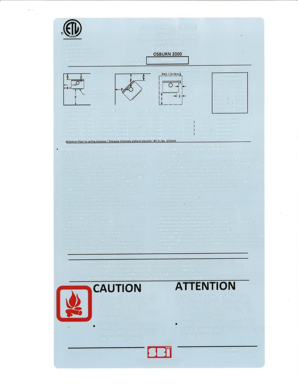
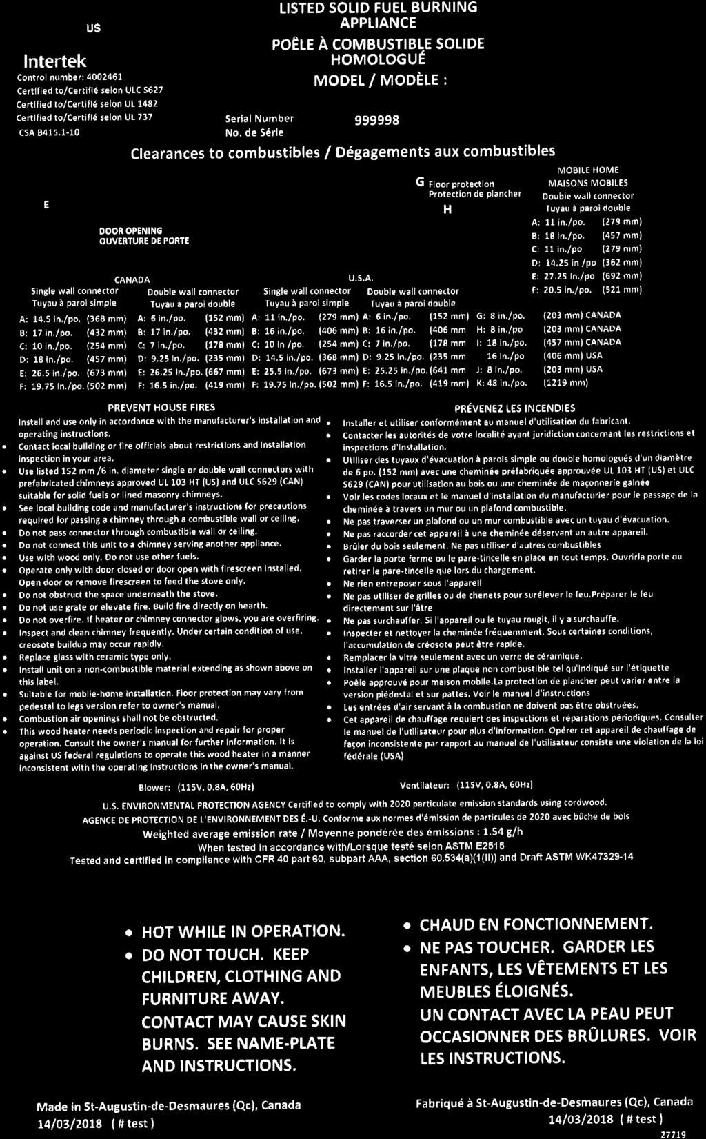
30 7. Clearances to Combustible Material The clearances shown in this section have been determined by test according to procedures set out in safety standards ULC S627 (Canada), UL 1482 (U.S.A.) and UL 737 (U.S.A.). When the stove is installed so that its surfaces are at or beyond the minimum clearances specified, combustible surfaces will not overheat under normal and even abnormal operating conditions. No part of the stove or flue pipe may be located closer to combustibles than the minimum clearance figures given. 7.1 Location of the Certification Label Since the information given on the certification label affixed to the appliance always overrides the information published, in any other media (owner s manual, catalogues, flyers, magazines and web sites) it is important to refer to it in order to have a safe and compliant installation. In addition, you will find information about your stove (model, serial number, etc.). You can find the certification label on the back of the stove. We recommend that you note the stove serial number on page 5 of this manual since it will be needed to precisely identify the version of the appliance in the event you require replacement parts or technical assistance. It is also recommended to register your warranty online. 7.2 Clearances to Combustible Materials The clearances to combustible walls may be slightly different in Canada and the U.S.A. and may also differ depending on whether you use single or double wall flue pipe. Please be sure to choose the correct clearance for your location and type of flue pipe. The clearances of the appliance and the flue pipes must be met individually, meaning the appliance can not be installed closer to the combustible materials than the single or double wall pipe allows. For a safe way to reduce clearances refer to section «7.4 Reducing Wall and Ceiling Clearances Safely» Page 30 Installation and Operation Manual
31 Figure 21: Clearances - Top Figure 22: Clearances - Side Figure 23: Clearances - Corner Installation and Operation Manual Page 31
32 APPLIANCE CLEARANCES (INSTALLATION WITH SINGLE WALL PIPE CONNECTOR) APPLIANCE CLEARANCES (INSTALLATION WITH DOUBLE WALL PIPE CONNECTOR) Canada USA Canada USA A 14 ½" (368 mm) 11" (279 mm) A 6" (152 mm) 6" (152 mm) B 17" (432 mm) 16" (406 mm) B 17" (432 mm) 16" (406 mm) C 10" (254 mm) 10" (254 mm) C 7" (178 mm) 7" (178 mm) K 48" (122 cm) 48" (122 cm) K 48" (122 cm) 48" (122 cm) L 84" (213 cm) 84" (213 cm) L 84" (213 cm) 84" (213 cm) If the above clearances are met, then the distances measured from the flue outlet will be: DISTANCES 1 FROM PIPE CONNECTOR WITH SINGLE WALL PIPE CONNECTOR DISTANCES 1 FROM PIPE CONNECTOR WITH DOUBLE WALL PIPE CONNECTOR Canada USA Canada USA D 18" (457 mm) 14 ½" (368 mm) D 9 ¼" (235 mm) 9 ¼" (235 mm) E 26 ½" (673 mm) 25 ½" (648 mm) E 26 ¼" (667 mm) 25 ¼" (641 mm) F 19 ¾" (502 mm) 19 ¾" (502 mm) F 16 ½" (419 mm) 16 ½" (419 mm) Clearances with heat shield AC02710 Note that to reduce the clearances of an appliance using a single wall pipe connector, the use of a heat shield certified with the single wall pipe connector to be used as close as 6" from combustible materials must be used. Only in this case, the same clearances as a certified double wall pipe connector can be used. APPLIANCE CLEARANCES (INSTALLATION WITH DOUBLE WALL PIPE CONNECTOR) DISTANCES 1 FROM DOUBLE WALL PIPE CONNECTOR Canada USA Canada USA A 3" (76 mm) 3" (76 mm) D 6 ¼" (159 mm) 6 ¼" (159 mm) B 4" (102 mm) 4" (102 mm) E 13 ¼" (337 mm) 13 ¼" (337 mm) C 3" (76 mm) 3" (76 mm) F 12 ½" (318 mm) 12 ½" (318 mm) K 48" (122 cm) 48" (122 cm) L 84" (213 cm) 84" (213 cm) 1 The pipe distances listed in this table refer to the distances obtained when the stove is installed in accordance with the appliance clearances above mentioned. Page 32 Installation and Operation Manual
33 7.2.2 Clearances With Ceiling (L) Lowered to 77" (196 cm) APPLIANCE CLEARANCES (INSTALLATION WITH SINGLE WALL PIPE CONNECTOR) APPLIANCE CLEARANCES (INSTALLATION WITH DOUBLE WALL PIPE CONNECTOR) Canada USA Canada USA A 14 ½" (368 mm) 11" (279 mm) A 9" (229 mm) 9" (229 mm) B 19" (483 mm) 18" (457 mm) B 19" (483 mm) 19" (483 mm) C 10" (254 mm) 10" (254 mm) C 7" (178 mm) 7" (178 mm) K 48" (122 cm) 48" (122 cm) K 48" (122 cm) 48" (122 cm) L 77" (196 cm) 77" (196 cm) L 77" (196 cm) 77" (196 cm) If the above clearances are met, then the distances measured from the flue outlet will be: DISTANCES FROM PIPE CONNECTOR WITH SINGLE WALL PIPE CONNECTOR DISTANCES 2 FROM PIPE CONNECTOR WITH DOUBLE WALL PIPE CONNECTOR Canada USA Canada USA D 18" (457 mm) 14 ½" (368 mm) D 12 ¼" (311 mm) 12 ¼" (311 mm) E 28 ½" (724 mm) 27 ½" (699 mm) E 28 ¼" (718 mm) 28 ¼" (718 mm) F 19 ¾" (502 mm) 19 ¾" (502 mm) F 16 ½" (419 mm) 16 ½" (419 mm) Clearances with heat shield (AC02710) and ceiling lowered to 77" (196 cm) Note that to reduce the clearances of an appliance using a single wall pipe connector, the use of a heat shield certified with the single wall pipe connector to be used as close as 6" from combustible materials must be used. Only in this case, the same clearances as a certified double wall pipe connector can be used. APPLIANCE CLEARANCES (INSTALLATION WITH DOUBLE WALL PIPE CONNECTOR) DISTANCES 2 FROM DOUBLE WALL PIPE CONNECTOR Canada USA Canada USA A 5" (127 mm) 5" (127 mm) D 8 ¼" (210 mm) 8 ¼" (210 mm) B 6" (152 mm) 6" (152 mm) E 15 ¼" (387 mm) 15 ¼" (387 mm) C 5" (127 mm) 5" (127 mm) F 14 ½" (368 mm) 14 ½" (368 mm) K 48" (122 cm) 48" (122 cm) L 80" (203 cm) 80" (203 cm) 2 The pipe distances listed in this table refer to the distances obtained when the stove is installed in accordance with the appliance clearances above mentioned. Installation and Operation Manual Page 33
34 7.2.4 Clearances in an alcove MOBILE HOME CLEARANCES (INSTALLATION WITH DOUBLE WALL PIPE CONNECTOR) DISTANCES 3 FROM PIPE CONNECTOR WITH DOUBLE WALL PIPE CONNECTOR Canada USA Canada USA A 9" (229 mm) 9" (229 mm) D 12 ¼" (311 mm) 12 ¼" (311 mm) B 19" (483 mm) 19" (483 mm) E 28 ¼ (718 mm) 28 ¼ (718 mm) K 48" (122 cm) 48" (122 cm) L 77" (196 cm) 77" (196 cm) Clearances For Mobile Homes It is strictly forbidden to install a unit with single wall pipe in a mobile home. MOBILE HOME CLEARANCES (INSTALLATION WITH DOUBLE WALL PIPE CONNECTOR) DISTANCES 3 FROM PIPE CONNECTOR WITH DOUBLE WALL PIPE CONNECTOR Canada USA Canada USA A 11" (279 mm) 11" (279 mm) D 14 ¼" (362 mm) 14 ¼" (362 mm) B 18" (457 mm) 18" (457 mm) E 27 ¼" (692 mm) 27 ¼" (692 mm) C 11" (279 mm) 11" (279 mm) F 20 ½" (521 mm) 20 ½" (521 mm) K 48" (122 cm) 48" (122 cm) L 84" (213 cm) 84" (213 cm) Clearances with heat shield AC02710 in a mobile home MOBILE HOME CLEARANCES (INSTALLATION WITH DOUBLE WALL PIPE CONNECTOR) DISTANCES 3 FROM PIPE CONNECTOR WITH DOUBLE WALL PIPE CONNECTOR Canada USA Canada USA A 3" (76 mm) 3" (76 mm) D 6 ¼" (159 mm) 6 ¼" (159 mm) B 6" (152 mm) 6" (152 mm) E 15 ¼" (387 mm) 15 ¼" (387 mm) C 3" (76 mm) 3" (76 mm) F 12 ½" (318 mm) 12 ½" (318 mm) K 48" (122 cm) 48" (122 cm) L 84" (213 cm) 84" (213 cm) 3 The pipe distances listed in this table refer to the distances obtained when the stove is installed in accordance with the appliance clearances above mentioned. Page 34 Installation and Operation Manual
35 7.3 Floor Protector If the stove is to be installed on top of a combustible floor, it must be guarded by a non combustible material as shown on figure Clearances to combustible materials and floor protection (see the dotted line area). Table 2 : Floor Protection* FLOOR PROTECTION Canada USA G 8" (203 mm)1 Note 1 N/A H 8" (203 mm) N/A I 18" (457 mm) From door opening 16" (406 mm) From door opening J N/A 8" (203 mm) N N/A Note 2 Figure 24: Floor Protection Important Note: Addition required to the floor protection when the stove is installed in a mobile home and assembled on legs version only: In addition to meeting the minimum size of the floor protection, the stove must be placed on a podium having a maximum dimension of 30 (762 mm) x 24 (610 mm) and a minimum height of 2 (51 mm). This podium can be constructed of combustible materials as long as it is covered of non-combustible materials. See figure beside. Figure 25: Floor protection for a mobile home *Steel with a minimum thickness of 0.015" (0.38 mm) or ceramic tiles sealed together with grout. No protection is required if the unit is installed on a non-combustible floor (ex: concrete). Note 1: The floor protection at the back of the stove is limited to the stove s required clearance if such clearance is smaller than 8 inches (203 mm). Note 2: Only required under the horizontal section of the connector. Must exceed each side of the connector by at least 2 inches (51 mm). See «Figure 22: Clearances - Side» Installation and Operation Manual Page 35

36 7.4 Reducing Wall and Ceiling Clearances Safely It is often desirable to reduce the minimum installation clearances by placing the stove closer to walls so the installation takes up less floor space. You can safely reduce the minimum clearances by permanently installing a shield between the stove and combustible material. The rules for safe shields can be complicated, so read them carefully and follow them exactly. Note that there may be minor regional differences in clearance reduction rules so be sure to check with your building or fire inspector before proceeding. Figure 26: Heat shield Shield Construction Rules See figures 26, 27 and 28 for shield construction to match each letter to a clearance. Adhesives used in shield construction must not ignite or lose adhesive qualities at temperatures likely to be encountered. Mounting hardware which extends from the shield surface into combustibles may be used only at the edges of the shield. Mounting hardware must allow full vertical ventilation. A) Minimum clearance between the appliance top and an unshielded combustible ceiling: 1181 mm (46 ½"). B) Shield extension above appliance: 500 mm (20"). C) Minimum space behind shield: 25 mm (1"). In Canada 21 mm (⅞"). D) Clearance along the bottom of shield: minimum: 25 mm (1") and maximum: 75 mm (3"). E) Minimum clearance along the top of shield at ceiling: 75 mm (3"). F) Mounting hardware must not be located closer than 200 mm (8") from the vertical centre line of the appliance. G) Edge clearance for ceiling shields to side and back walls: 75 mm (3"). H) Shield extension beyond each side of appliance: 450 mm (18"). Page 36 Installation and Operation Manual


37 Figure 27: Heat shield clearances Figure 28: Heat shield clearances Figure 29: Heat shield clearances Installation and Operation Manual Page 37
38 CLEARANCES MAY BE REDUCED BY THESE PERCENTAGES TYPE OF SHIELD SIDES AND REAR TOP (CEILING) CAN /USA (%) USA MIN. CAN /USA (%) USA MIN. Sheet metal, a minimum of 24 gauge (0.61 mm) in thickness, spaced out at least 25 mm (1 in)* by non-combustible spacers in in Ceramic tiles, or equivalent non-combustible material, on non-combustible board spaced out at least 25 mm (1 in)* by non-combustible spacers in in Ceramic tiles, or equivalent non-combustible material, on non-combustible board, with a minimum of 24 gauge (0.61 mm) sheet metal backing spaced out at least 25 mm (1 in)* by non-combustible spacers in in Brick, spaced out at least 25 mm (1 in)* by non-combustible spacers in N/A N/A Brick, with a minimum of 24 gauge (0.61 mm) sheet metal backing, spaced out at least 25 mm (1 in)* by non-combustible spacers in N/A N/A Page 38 Installation and Operation Manual
39 8. The Venting System 8.1 General The venting system, made up of the chimney and the connecting pipe between the stove and the chimney, acts as the engine that drives your wood heating system. Even the best stove will not function safely and efficiently as intended if it is not connected to a suitable chimney. The heat in the flue gases that pass from the stove and chimney connector into the chimney is not waste heat. This heat is what the chimney uses to make the draft that draws in combustion air, keeps smoke inside the stove and safely vents exhaust to outside. You can think of heat in the flue gas as the fuel the chimney uses to make draft. 8.2 Suitable Chimneys Your wood stove will provide optimum efficiency and performance when connected to a 6-inch diameter chimney flue system. The connection to a chimney having a diameter of at least 5 inches (Canada only) or no more than 7 inches is permitted, if it allows the proper venting of combustion gases and that such application is verified and authorized by a qualified installer. Otherwise, the diameter of the flue should be 6 inches. To be suitable, a factory-built metal chimney must comply with UL 103HT (U.S.A.) or ULC S629 (Canada) Factory-Built Metal Chimneys These are sometimes referred to as high temp chimneys because they have the special characteristics to withstand the temperatures that can be created by wood burning stoves. Factory-built chimneys are tested as a system with all the necessary components for installation. The instructions provided with the chimney by its manufacturer are the only reliable source of installation guidelines. To be safe and effective, the chimney must be installed exactly in accordance with the manufacturer s instructions. Use only components intended for the brand and model of chimney you are using. Never substitute parts from other chimney brands or fabricate your own components. The chimney must be a type suitable for solid fuel. Installation and Operation Manual Page 39
40 8.2.2 Factory-Built Metal Chimneys in Mobile Homes For use in a mobile home, this stove is to be connected to a 6 in diameter double wall factory built chimney conforming to CAN/UCL-S629, Standards for 650 C Factory-built chimney. The total length of the flue system should be at least 12 feet including elbows, from the top of the stove. To maintain an effective vapour barrier, insulation and waterproof at the chimney and outside flue pipe, install a mobile home roof flashing and seal it with silicone Masonry Chimneys The stove may also be connected to a masonry chimney, provided the chimney complies with the construction rules found in the building code enforced locally. The chimney must have either a clay liner or a suitably listed stainless steel liner. If the masonry chimney has a square or rectangular liner that is larger in cross sectional area than a round 6 flue, it should be relined with a suitably listed 6 stainless steel liner. Do not downsize the flue to less than 6 unless the venting system is straight and exceeds 25 feet in height. When passing through a combustible wall, the use of an insulated listed thimble is required. Page 40 Installation and Operation Manual
41 8.3 Minimum Chimney Height The top of the chimney should be tall enough to be above the air turbulence caused when wind blows against the house and its roof. The chimney must extend at least 1 m (3 ft.) above the highest point of contact with the roof, and at least 60 cm (2 ft.) higher than any roof line or obstacle within a horizontal distance of 3 m (10 ft.). 8.4 The Relationship Between the Chimney and the House Because the venting system is the engine that drives the wood heating system, it must have the right characteristics. The signs of bad system design are cold backdrafting when there is no fire in the stove, slow kindling of new fires, and smoke roll-out when the door is opened for loading. There are two guidelines to follow. First, the chimney should be installed up through the heated space of the house, not out and up an outside wall. Second, the chimney should penetrate the top of the building at or near the highest heated space Why Inside Chimneys Are Preferred Venting systems that rise straight up from the stove flue collar provide the best performance. Chimneys that rise inside the warm space of the house tend to provide a small amount of draft even when there is no fire burning. This means that when you light a fire, the initial smoke goes up the chimney and strong draft builds quickly as the chimney flue warms up. Although they are common in North America, chimneys that exit a house wall and run up outside can cause problems. Figure 30: Good System Design Figure 31: Inferior System Design Installation and Operation Manual Page 41

42 8.4.2 Why the Chimney Should Penetrate the Highest Heated Space When it is cold outside, the warm air in the house is buoyant so it tends to rise. This tendency of warm air to rise creates a slight pressure difference in the house. Called stack effect, it produces a slightly negative pressure low in the house (relative to outside) and a slightly positive pressure zone high in the house. If there is no fire burning in a heater connected to a chimney that is shorter than the warm space inside the house, the slight negative pressure low in the house will compete against the desired upward flow in the chimney. There are two reasons why the chimney in the house at right will cold backdraft when it is cold outside and there is no fire burning in the stove. First, the chimney runs up the outside of the house, so the air in it is colder and denser than the warm air in the house. And second, the chimney is shorter than the heated space of the house, meaning the negative pressure low in the house will pull outside air down the chimney, through the stove and into the room. Even the finest stove will not work well when connected to this chimney. Figure 32: Chimney location in the house 8.5 Supply of Combustion Air In Canada, wood stoves are not required to have a supply of combustion air from outdoors because research has shown that these supplies do not give protection against house depressurization and may fail to supply combustion air during windy weather. However, to protect against the risk of smoke spillage due to house depressurization, a carbon monoxide (CO) detector/alarm is required in the room in which the stove is installed. The CO detector will provide warning if for any reason the wood stove fails to function correctly Combustion Air Supply in Mobile Homes Only a wood stove certified and labelled as mobile home approved may be installed in a mobile home. This Osburn 2000 stove is mobile home approved. Wood stoves installed in mobile homes must have a ducted supply of combustion air from outdoors. This air supply should be routed down through the house floor into the vented crawl space under the mobile home. The air supply duct should be non-combustible aluminum flex duct with a screened weatherhood on the outside end. Note: Fabric duct may also be used, provided it is suitable for HVAC use and meets the requirements of ULC-S110 or UL-181 Class 1 standards. It must have a non-combustible insulation and be corrosion resistant. Where a mobile home has been converted to a standard house by mounting it on a permanent basement foundation, the supply of outdoor air is not required. Page 42 Installation and Operation Manual
Installation and Operation Manual HT-2000 (DB07200 model)
") Installation and Operation Manual HT-2000 (DB07200 model) US ENVIRONMENTAL PROTECTION AGENCY PHASE II CERTIFIED WOOD STOVE Safety tested according to ULC S627 and UL 1482 Standards by an accredited laboratory.
Installation and Operation Manual HT-2000 (DB07200 model) US ENVIRONMENTAL PROTECTION AGENCY PHASE II CERTIFIED WOOD STOVE Safety tested according to ULC S627 and UL 1482 Standards by an accredited laboratory.
Installation and Operation Manual S244 (CB00001 model)
") Installation and Operation Manual S244 (CB00001 model) US ENVIRONMENTAL PROTECTION AGENCY PHASE II CERTIFIED WOOD STOVE Safety tested according to ULC S627, UL 737 and UL 1482 Standards by an accredited
Installation and Operation Manual S244 (CB00001 model) US ENVIRONMENTAL PROTECTION AGENCY PHASE II CERTIFIED WOOD STOVE Safety tested according to ULC S627, UL 737 and UL 1482 Standards by an accredited
Installation and Operation Manual Deco (DB03200 model)
") Installation and Operation Manual Deco (DB03200 model) US ENVIRONMENTAL PROTECTION AGENCY PHASE II CERTIFIED WOOD STOVE Safety tested according to ULC S627, UL 737 and UL 1482 Standards by an accredited
Installation and Operation Manual Deco (DB03200 model) US ENVIRONMENTAL PROTECTION AGENCY PHASE II CERTIFIED WOOD STOVE Safety tested according to ULC S627, UL 737 and UL 1482 Standards by an accredited
INSTALLATION AND OPERATION MANUAL.
 INSTALLATION AND OPERATION MANUAL 2200 (OB02211 model) US ENVIRONMENTAL PROTECTION AGENCY PHASE II CERTIFIED WOOD STOVE Safety tested according to ULC S627 and UL 1482 Standards by an accredited laboratory
Installation and Operation Manual Rocket (DB03185 model)
") Installation and Operation Manual Rocket (DB03185 model) US ENVIRONMENTAL PROTECTION AGENCY PHASE II CERTIFIED WOOD STOVE Safety tested according to ULC S627, UL 737 and UL 1482 Standards by an accredited
Installation and Operation Manual Rocket (DB03185 model) US ENVIRONMENTAL PROTECTION AGENCY PHASE II CERTIFIED WOOD STOVE Safety tested according to ULC S627, UL 737 and UL 1482 Standards by an accredited
Installation and Operation Manual HT-2000 (DB07200 Model)
") Installation and Operation Manual HT-2000 (DB07200 Model) US ENVIRONMENTAL PROTECTION AGENCY PHASE II CERTIFIED WOOD STOVE Safety tested according to ULC S627, and UL 1482 Standards by an accredited laboratory.
Installation and Operation Manual HT-2000 (DB07200 Model) US ENVIRONMENTAL PROTECTION AGENCY PHASE II CERTIFIED WOOD STOVE Safety tested according to ULC S627, and UL 1482 Standards by an accredited laboratory.
INSTALLATION AND OPERATION MANUAL Solution 1.3 (EB00011 model)
") INSTALLATION AND OPERATION MANUAL Solution 1.3 (EB00011 model) US ENVIRONMENTAL PROTECTION AGENCY PHASE II CERTIFIED WOOD STOVE Safety tested according to ULC S627, UL 737 and UL 1482 Standards by an accredited
INSTALLATION AND OPERATION MANUAL Solution 1.3 (EB00011 model) US ENVIRONMENTAL PROTECTION AGENCY PHASE II CERTIFIED WOOD STOVE Safety tested according to ULC S627, UL 737 and UL 1482 Standards by an accredited
INSTALLATION AND OPERATION MANUAL
 INSTALLATION AND OPERATION MANUAL 2300 (OB02302 model) US ENVIRONMENTAL PROTECTION AGENCY PHASE II CERTIFIED WOOD STOVE Safety tested according to ULC S627 and UL 1482 Standards by an accredited laboratory
Installation and Operation Manual Escape 1800 (DB03102, DB03111 & DB03112 models)
") Installation and Operation Manual Escape 1800 (DB03102, DB03111 & DB03112 models) US ENVIRONMENTAL PROTECTION AGENCY PHASE II CERTIFIED WOOD STOVE Safety tested according to ULC S627, UL 737 and UL 1482
Installation and Operation Manual Escape 1800 (DB03102, DB03111 & DB03112 models) US ENVIRONMENTAL PROTECTION AGENCY PHASE II CERTIFIED WOOD STOVE Safety tested according to ULC S627, UL 737 and UL 1482
INSTALLATION AND OPERATION MANUAL.
 INSTALLATION AND OPERATION MANUAL OSBURN 2000 US ENVIRONMENTAL PROTECTION AGENCY PHASE II CERTIFIED WOOD STOVE Safety tested according to ULC S627, UL 737 and UL 1482 Standards by Intertek Testing Services
Installation and Operation Manual Baltic II (DB03041 model)
") Installation and Operation Manual Baltic II (DB03041 model) US ENVIRONMENTAL PROTECTION AGENCY PHASE II CERTIFIED WOOD STOVE Safety tested according to ULC S627 and UL 1482 Standards by an accredited laboratory
Installation and Operation Manual Baltic II (DB03041 model) US ENVIRONMENTAL PROTECTION AGENCY PHASE II CERTIFIED WOOD STOVE Safety tested according to ULC S627 and UL 1482 Standards by an accredited laboratory
INSTALLATION AND OPERATION MANUAL. mfg.com
 INSTALLATION AND OPERATION MANUAL SOHO US ENVIRONMENTAL PROTECTION AGENCY PHASE II CERTIFIED WOOD STOVE Safety tested according to ULC S627, UL 737 and UL 1482 Standards by an accredited laboratory www.osburn
Installation and Operation Manual S244
 Installation and Operation Manual S244 US ENVIRONMENTAL PROTECTION AGENCY PHASE II CERTIFIED WOOD STOVE Safety tested according to ULC S627, UL 737 and UL 1482 Standards by Intertek Testing Services www.century-heating.com
Installation and Operation Manual Austral II (DB03031 model)
") Installation and Operation Manual Austral II (DB03031 model) US ENVIRONMENTAL PROTECTION AGENCY PHASE II CERTIFIED WOOD STOVE Safety tested according to ULC S627 and UL 1482 Standards by an accredited
Installation and Operation Manual Austral II (DB03031 model) US ENVIRONMENTAL PROTECTION AGENCY PHASE II CERTIFIED WOOD STOVE Safety tested according to ULC S627 and UL 1482 Standards by an accredited
INSTALLATION AND OPERATION MANUAL Solution 2.3 (EB00012 model)
") INSTALLATION AND OPERATION MANUAL Solution 2.3 (EB00012 model) US ENVIRONMENTAL PROTECTION AGENCY PHASE II CERTIFIED WOOD STOVE Safety tested according to ULC S627, UL 737 and UL 1482 Standards by an accredited
INSTALLATION AND OPERATION MANUAL Solution 2.3 (EB00012 model) US ENVIRONMENTAL PROTECTION AGENCY PHASE II CERTIFIED WOOD STOVE Safety tested according to ULC S627, UL 737 and UL 1482 Standards by an accredited
Installation and Operation Manual Escape 1800 DB03101, DB03102, DB03111, DB03112 & DB03113 models
 Installation and Operation Manual Escape 1800 DB03101, DB03102, DB03111, DB03112 & DB03113 models US ENVIRONMENTAL PROTECTION AGENCY PHASE II CERTIFIED WOOD STOVE Safety tested according to ULC S627, UL
Installation and Operation Manual Blackcomb
 Installation and Operation Manual Blackcomb US ENVIRONMENTAL PROTECTION AGENCY PHASE II CERTIFIED WOOD STOVE Safety tested according to ULC S627 and UL 1482 Standards by Intertek Testing Services www.drolet.ca
Savannah (DB03025 model)
") Installation and Operation Manual Savannah (DB03025 model) US ENVIRONMENTAL PROTECTION AGENCY PHASE II CERTIFIED WOOD STOVE Safety tested according to ULC S627, UL 737 and UL 1482 Standards by an accredited
Installation and Operation Manual Savannah (DB03025 model) US ENVIRONMENTAL PROTECTION AGENCY PHASE II CERTIFIED WOOD STOVE Safety tested according to ULC S627, UL 737 and UL 1482 Standards by an accredited
Installation and Operation Manual Eastwood 1800 (DB03161 model)
") Installation and Operation Manual Eastwood 1800 (DB03161 model) US ENVIRONMENTAL PROTECTION AGENCY PHASE II CERTIFIED WOOD STOVE Safety tested according to ULC S627 and UL 1482 Standards by an accredited
Installation and Operation Manual Eastwood 1800 (DB03161 model) US ENVIRONMENTAL PROTECTION AGENCY PHASE II CERTIFIED WOOD STOVE Safety tested according to ULC S627 and UL 1482 Standards by an accredited
Installation and Operation Manual XVR-II SE (FL023W model)
") Installation and Operation Manual XVR-II SE (FL023W model) US ENVIRONMENTAL PROTECTION AGENCY PHASE II CERTIFIED WOOD STOVE Safety tested according to ULC S627, UL 737 and UL 1482 Standards by an accredited
Installation and Operation Manual XVR-II SE (FL023W model) US ENVIRONMENTAL PROTECTION AGENCY PHASE II CERTIFIED WOOD STOVE Safety tested according to ULC S627, UL 737 and UL 1482 Standards by an accredited
Figure 1:This chimney and flue pipe arrangement gives the best performance
 A bout your HOUSE Efficient, Convenient wood heating CE 57 Introduction More than one million Canadian families heat their homes at least partly with wood. For these households wood is an important energy
For Outdoor Use Only!
 ITEM NAME: Red Ember 4 ft. Smokestack Rubbed Bronze Fireplace with Cover SKU: ALZ655-1 For Outdoor Use Only! 1. Improper installation, adjustment, alteration, service or maintenance can cause injury or
Please read this manual before installation and use. We wish you many years of pleasure and warmth.
 Thank you for purchasing this product. This multi fuel burning stove is compliant with the EN13240 Please read this manual before installation and use. We wish you many years of pleasure and warmth. Manufactured
Installation & User Manual EW5000 Outdoor Cooking Fire
 Installation & User Manual EW5000 Outdoor Cooking Fire IMPORTANT: Please read this manual before installing and using the ESCEA EW5000 Cooking fire. Failure to follow these instructions may lead to a possible
For Outdoor Use Only!
 ITEM NAME: Red Ember Bronze Crossweave Firebowl Fire Pit with Free Cover and Fire Tool with Optional Grill Grate SKU: ALZ109 For Outdoor Use Only! 1. Improper installation, adjustment, alteration, service
EXCEL ULTRABlack FS 6 Clearance Connector INSTALLATION AND MAINTENANCE INSTRUCTIONS
 EXCEL ULTRABlack FS 6 Clearance Connector INSTALLATION AND MAINTENANCE INSTRUCTIONS A MAJOR CAUSE OF CHIMNEY RELATED FIRES IS FAILURE TO MAINTAIN REQUIRED CLEARANCES (AIR SPACE) TO COMBUSTIBLE MATERIALS.
Alma Mons EN Owners s manual INSTALATION, ADJUSTMENT AND OPERATING INSTRUCTION
 Alma Mons Owners s manual INSTALATION, ADJUSTMENT AND OPERATING INSTRUCTION EN 12815 1 INTRODUCTION Congratulations! You have invested in energy efficient and high quality product-alma Mons wood burning
HARVIA IRON STOVE Instructions for installation and use
 HARVIA IRON STOVE EN Instructions for installation and use Harvia 10 08012014VTT Congratulations on a good choice of fireplace and thank you for your confidence in Harvia s products. Read these instructions
MODEL DCC DOUBLE WALL CHIMNEY CONNECTOR
 Installation & Maintenance LISTED Tested to *UL 103HT & ULC-S641 Instructions MODEL DCC DOUBLE WALL CHIMNEY CONNECTOR A MAJOR CAUSE OF CHIMNEY RELATED FIRES IS FAILURE TO MAINTAIN REQUIRED CLEARANCES (AIR
MODEL DCC DOUBLE WALL CHIMNEY CONNECTOR
 Installation & Maintenance LISTED Tested to *UL 103HT & ULC-S641 Instructions MODEL DCC DOUBLE WALL CHIMNEY CONNECTOR A MAJOR CAUSE OF CHIMNEY RELATED FIRES IS FAILURE TO MAINTAIN REQUIRED CLEARANCES (AIR
Assembly Instructions & User s Manual 26 Florence Folding Leg Fire Pit
 Assembly Instructions & User s Manual 26 Florence Folding Leg Fire Pit FSMVPT6022 Please keep this instruction manual for future reference Customer Service: (888) 922-2336 7:00 am to 2:00 am CST (daily)
Inspecting your combustor
 Inspecting your combustor Ash, a fluffy light grey powder, and soot, a darker granular material, accumulate on the combustor surfaces in normal use. Ashes accumulate both as a result of the smoke being
Tips For Using a Catalytic Woodstove
 5555 Pleasantdale Road Doraville, GA 30340 678-735-4937 Tips For Using a Catalytic Woodstove By Mike Preetorius, Customer Service A model of your stove was sent to Environmental Protection Agency for testing
Studio stove, Studio oven and Oh-Ah
 Studio stove, Studio oven and Oh-Ah Maintenance and Operating Instructions Visit www.warmington.co.nz for specs, DWG s and PDF uploads of fires Fire, flue system and instructions to comply with AS/NZS
OSBURN MODEL 1000 FREESTANDING STOVE (OB01010)
") OWNER S MANUAL OSBURN MODEL 1000 FREESTANDING STOVE (OB01010) Distributed by Glen Dimplex Australasia NEW ZEALAND 38 Harris Road, East Tamaki, Auckland Ph: 09 274 8265 Fax 09 274 8472 Email:sales@glendimplex.co.nz
OWNER S MANUAL OSBURN MODEL 1000 FREESTANDING STOVE (OB01010) Distributed by Glen Dimplex Australasia NEW ZEALAND 38 Harris Road, East Tamaki, Auckland Ph: 09 274 8265 Fax 09 274 8472 Email:sales@glendimplex.co.nz
How to use a multi fuel stove
 How to use a multi fuel stove Important!! When lighting the stove for the first time only a small fire should be lit. Too hot a fire will result in the paint emitting smoke - not necessarily bad but unpleasant.
MODEL DL INSTALLATION AND OPERATING INSTRUCTIONS 2100º F 1150º C
 6", 7" & 8" dia. MODEL DL DOUBLE WALL CONNECTOR INSTALLATION AND OPERATING INSTRUCTIONS THIS STOVE CONNECTOR HAS BEEN LISTED AT 2100º F 1150º C LISTED ACCORDING TO: ULC-S641 WH-PN-016 SECURITY CHIMNEYS
DIANA EN Owners s manual INSTALATION, ADJUSTMENT AND OPERATING INSTRUCTION. Available in ceramic and metalsheet version.
 DIANA Owners s manual INSTALATION, ADJUSTMENT AND OPERATING INSTRUCTION Available in ceramic and metalsheet version. EN 13240 1 INTRODUCTION Congratulations! You have invested in energy efficient and high
Seasoning Your Stove. Starting a Fire And Establishing Proper Draft
 OPERATION Seasoning Your Stove Both soapstone and steel need to be seasoned. The seasoning can be accomplished through a series of small to moderate fires. Your Woodstock Soapstone Stove is an easy stove
OSBURN 900 WOOD STOVE
 OWNER S MANUAL OSBURN 900 WOOD STOVE Distributed by Glen Dimplex Australasia NEW ZEALAND 38 Harris Road, East Tamaki, Auckland Ph: 09 274 8265 Fax 09 274 8472 Email: sales@glendimplex.co.nz www.glendimplex.com.au
Installation and Operating. Instructions. Multifuel Stove. Salamander. Model Lighting a solid fuel fire. 6.5 De-ashing the stove
 Installation and Operating Instructions Salamander Model 0901 Multifuel Stove Section Contents Page 1 Important information about installing and 3 using the Salamander stove 2 Unpacking the Salamander
THE INSTALLATION MANUAL FOR GEMINI 1200 AND GEMINI 1500 WOODSTOVES. Manufactured by DROLET STOVES & FIREPLACES INC.
 THE INSTALLATION MANUAL FOR GEMINI 1200 AND GEMINI 1500 WOODSTOVES Manufactured by DROLET STOVES & FIREPLACES INC. Rev 07/96 45041a THE INSTALLATION MANUAL FOR GEMINI 1200 ET GEMINI 1500 WOODSTOVES DROLET
USAGE AND MAINTENANCE MANUAL FOR A SOLID FUEL STOVE
 PREDUZEĆE ZA PROIZVODNJU, PROJEKTOVANJE I PROMET BELOŠEVAC BB, 14000 VALJEVO, SRBIJA USAGE AND MAINTENANCE MANUAL FOR A SOLID FUEL STOVE DEAR CUSTOMER, Congratulations on your purchase of BLIST solid fuel
Seasoning Your Stove. Starting a Fire And Establishing Proper Draft
 OPERATION Seasoning Your Stove Both soapstone and steel need to be seasoned. The seasoning can be accomplished through a series of small to moderate fires. Your Woodstock Soapstone Stove is an easy stove
MULTI-FUEL STOVE INSTALLATION AND USER INSTRUCTIONS
 PRIORY MULTI-FUEL STOVE INSTALLATION AND USER INSTRUCTIONS The Priory stove has a nominal heat output of 8Kw. and a weight of 80 kg. The flue gas mass flow is 5.4g/s for mineral fuel and 6.3g/s for wood
INSTALLATION AND OPERATIONS GUIDE FOR GRAND CANYON GAS JUMBO/JUMBO SLIMLINE LOG SYSTEMS
 Burner Systems: JUMBOSLIMBRNR-24 JUMBOSLIMBRNR-30 JUMBOBRNR-36 / JUMBOSLIMBRNR-36 JUMBOBRNR-42 / JUMBOSLIMBRNR-42 JUMBOBRNR-48 / JUMBOSLIMBRNR-48 JUMBOBRNR-60 / JUMBOSLIMBRNR-60 INSTALLATION AND OPERATIONS
A carbon monoxide detector has been supplied with your stove. You must plug it in. Burn Nut and Pea anthracite coal only
 70,000 & 90,000 Hand Fired Deep Box Operating instructions and maintenance enclosed Thoroughly read and understand instructions Always leave this manual with stove owner Follow the instructions within
Mod. MONTANA WOOD BURNING STOVE USAGE AND MAINTENANCE INSTRUCTIONS
 Mod. MONTANA WOOD BURNING STOVE USAGE AND MAINTENANCE INSTRUCTIONS Nutrients Ashes Fertilizer Wood: an ecological fuel Wood is a renewable source of energy which answers the energy and environmental demands
TWO BURNER STAINLESS STEEL PROPANE STOVE
 ROTATE TO LIGHT 842-A250-0_SSCmpStove.qxd 11/26/03 2:59 PM Page 1 OWNER S MANUAL FAILURE TO FOLLOW ALL S AND INSTRUCTIONS IN THIS MANUAL COULD LEAD TO PERSONAL INJURY, INCLUDING DEATH. RETAIN THIS MANUAL
Installation Instructions
 Installation Instructions For use in and IE only C i4 FS www.contura.eu 2 CERTIFICATE DECLARATION OF PERFORMANCE No. Ci4FS-CPR-130619-SE-1 PRODUCT Product type Type designation Manufacturing number Intended
SHERWOOD INDUSTRIES IS AN ENVIRONMENTALLY RESPONSIBLE COMPANY. THIS MANUAL IS PRINTED ON RECYCLED PAPER. OWNER S MANUAL
 SHERWOOD INDUSTRIES IS AN ENVIRONMENTALLY RESPONSIBLE COMPANY. THIS MANUAL IS PRINTED ON RECYCLED PAPER. PLEASE KEEP THESE INSTRUCTIONS FOR FUTURE REFERENCE PELLET STOVE Windsor OWNER S MANUAL PLEASE READ
INSTRUCTIONS FOR INSTALLATION, USE AND MAINTENANCE YSEN
 INSTRUCTIONS FOR INSTALLATION, USE AND MAINTENANCE YSEN READ THE INSTRUCTION BOOKLET AND THESE SUPPLEMENTARY INSTRUCTIONS CAREFULLY BEFORE INSTALLATION These instructions together with those in the instruction
Care and Replacement Manual for Woodstove Catalytic Combustors
 Care and Replacement Manual for Woodstove Catalytic Combustors A good combustor is designed to withstand approximately 12,000 hours of continuous use. For most people, this will translate into two to five
BRANDON PIZZA OVEN INSTALLATION GUIDE AND OWNER S MANUAL
 BRANDON PIZZA OVEN INSTALLATION GUIDE AND OWNER S MANUAL TABLE OF CONTENTS COMPONENTS... 3 OVERALL DIMENSIONS.... 4 POSITIONING REFERENCE PER LAYER... 5 CONCRETE PAD PREPARATION... 5 INSTALLATION OF BLOCKS...
Harrie Leenders Fuga el - Instructions for Installation, Use and Maintenance INSTRUCTIONS FOR INSTALLATION, USE AND MAINTENANCE
 INSTRUCTIONS FOR INSTALLATION, USE AND MAINTENANCE FUGA el 1 2 1. Flue 2. Case 3. Ceramic glass 4. Aeration slide 5. Convection fins 6. Door handle 7. Base 3 4 READ THE INSTRUCTION BOOKLET AND THESE SUPPLEMENTARY
Setting Up Your Stove
 OPERATION Setting Up Your Stove 11. Your Palladian/Keystone has been shipped fully assembled except for three parts: 1) The bottom heat shield, 2) The flue collar/cover plate, and 3) the knob for the bypass
How to Use and Enjoy your New Stove
 How to Use and Enjoy your New Stove Welcome to Your New Stove Now that you re the proud owner of a new stove, we felt it would be a good idea to offer some advice on how to keep safe and achieve the best
INSTALLATION AND OPERATIONS GUIDE FOR GRAND CANYON GAS LOG FIRE PIT SERIES ONLY
 INSTALLATION AND OPERATIONS GUIDE FOR GRAND CANYON GAS LOG FIRE PIT SERIES ONLY Installation and service must be provided by a qualified installer, service agency or gas supplier Grand Canyon Gas Logs,
You recognize it immediately. The shape, the name, the quality. The Harman. P-Series gives you the heat you want when you want it.
 P - S E R I E S P e l l e t S t o v e s The Smartest pellet stoves on the market Decorative plated or brushed air grilles (optional) Sealed hopper holds up to 76 pounds of pellets State-of-the-art, whisperquiet,
OPERATING INSTRUCTIONS
 OPERATING INSTRUCTIONS SCANDIA 6304 2015 www.heta.dk UK 1 Congratulations on your new stove. We are sure that you will be happy with your investment, especially if you follow the advice and instructions
IN THE EVENT OF CHIMNEY FIRE, EVACUATE THE PROPERTY AND CALL THE EMERGENCY SERVICES.
 EKOL INSET 8 INSTALLATION AND OPERATING INSTRUCTIONS INTRODUCTION. SAFETY Safety is the most important consideration when using and installing your stove. If not installed and used correctly, a house fire
17500 VRANJE, SRBIJA Radnička 1, Tel.: 017/ INSTRUCTIONS FOR INSTALLATION, ADJUSTMENT AND USE
 17500 VRANJE, SRBIJA Radnička 1, Tel.: 017/421-121 STOVE OF THICK METAL SHEETS PREMIJER PREMIJER K INSTRUCTIONS FOR INSTALLATION, ADJUSTMENT AND USE 1.Technical data about continuously burning stove of
Model 205 Fireview Maintenance Kit
 Model 205 Fireview Maintenance Kit Please read all of the instructions before you begin the procedure. Confirm that you have all the necessary tools and parts required. Allow about one hour to complete
Wood as Fuel. Chimney sweeps in particular have a unique opportunity to deliver information on good burning habits to their customers.
 Wood as Fuel This document is intended to supply additional background information to compliment the consumer awareness information in Burn Right We all breathe the same air Chimney sweeps in particular
Wood Burning Stove Safety Tips
 Why a Stove Burner? & Wood vs Multi Fuel Stove Wood Burning Stove Safety Tips Nothing creates the perfect ambiance on a cold winter s day than the warmth from a wood burner. The popularity of burning wood
Installation Instructions
 Installation Instructions C 710 www.contura.eu 50 CERTIFICATE Declaration of performance according to Regulation (EU) 305/2011 No. C710-CPR-160329-SE-1 PRODUCT Product type Stove lit with solid biofuels
INSTALLATION/OWNERS MANUAL for. Kodiak HAND FIRED GRAVITY FED COAL STOVE Columbia Blvd. Bloomsburg PA Fuel: Nut or Pea Coal
 INSTALLATION/OWNERS MANUAL for Kodiak HAND FIRED GRAVITY FED COAL STOVE 3162 Columbia Blvd. Bloomsburg PA 17815 Fuel: Nut or Pea Coal Caution Fossil fuel burning can create lethal doses of carbon monoxide
TCWS.38NG03.C BLACK DIAMOND BURNER KIT INSTRUCTIONS
 IMPORTANT: THESE INSTRUCTIONS ARE TO REMAIN WITH THE HOMEOWNER These instructions are supplementary to the Installation and Operating Instructions supplied with the fireplace and should be kept together.
SINGLE BURNER STOVE IMPORTANT OPERATING INSTRUCTIONS COOKING & STORAGE POSITION PARTS IDENTIFICATION
 SINGLE BURNER STOVE OPERATING INSTRUCTIONS PARTS IDENTIFICATION Electronic Lighter Ignites the burner. Liquid Guard Holds liquid overflow. Windshield Prevents flame from being extinguished by wind. Ensures
Installation and Operating Instructions
 Installation and Operating Instructions Wood-burning Stove Model: Ottawa 7kw INTRODUCTION Wood-burning Stove Item No.: Ottawa 7kw SAFETY Safety is the most important consideration when using and installing
OWNER`S MANUAL 2400 MODEL STOVE
 OWNER`S MANUAL 2400 MODEL STOVE US ENVIRONMENTAL PROTECTION AGENCY PHASE II CERTIFIED WOODSTOVE Verified and tested following ULC S627 and UL 1482 Standards by: Manufactured by: STOVE BUILDER INTERNATIONAL
TCWS54 SEE THRU DIAMOND BURNER INSTALLATION KIT INSTRUCTIONS
 INSTALLER: Leave this manual with the appliance. CONSUMER: Retain this manual for future reference. These instructions are supplementary to the Installation and Operating Instructions supplied with the
CONTENTS. INSTALLATION INSTRUCTIONS Building regulations 4 Positioning and Clearances 4 Chimney 4 Flue connection 5 Problem solving 6 PRODUCT DATA
 PRODUCT DATA MODEL WEIGHT NOMINAL HEAT OUTPUT FB1 DS 80KG 6KWs CONTENTS OPERATING INSTRUCTIONS Lighting the fire 2 Firebox linings and baffle 2 Wood burning tips & theory 2 Running temperatures 3 Cleaning
Installation instruction
 Installation instruction C 35T-Low www.contura.eu 82 CERTIFICATE PERFORMANCE DECLARATION No. C35TL-CPR-130618-SE-1 PRODUCT Product type Type designation Manufacturing number Intended area of use Fuel Stove
Outdoor Fireplace. Model No. WAD906SP. Table of Contents
 OWNER S MANUAL Outdoor Fireplace Model No. WAD906SP For Outdoor Use Only (outside any enclosure) WARNING FOR YOUR SAFETY: Table of Contents Important Safeguards...........................................
Installation Instructions
 Installation Instructions C 780 www.contura.eu 50 CERTIFICATE PERFORMANCE DECLARATION No. C780-CPR-130612-SE-1 PRODUCT Product type Stove lit with solid biofuels Type designation Contura 780 Manufacturing
APPENDIX TO THE INSTALLATION AND OPERATING MANUAL OF STOVEMAN SAUNA STOVE
 APPENDIX TO THE INSTALLATION AND OPERATING MANUAL OF STOVEMAN SAUNA STOVE Technical data of the sauna stove Sauna stove type Stoveman 16 Model Stoveman 16 Nominal heat capacity, i.e. ability to 17 kw heat
CERO Instructions for use and safety
 CERO Instructions for use and safety READ CAREFULLY BEFORE USE Please store these safety warnings in a safe place for future reference. NOTICE: BUYER ASSUMES ALL RESPONSIBILITY FOR SAFETY AND USE THAT
Lit Table Top Firepit Bio-Ethanol Fireplace. User Manual. Model: GF301650
 Lit Table Top Firepit Bio-Ethanol Fireplace User Manual Model: GF301650 1 Moda Flame Lit Table Top Firepit Bio-Ethanol Fireplace Included in delivery (Parts List): A. Fireplace body 1pc B. Glass 1pc C.
made by made by NEW UK 17/18
 NEW made by A true Viking Raw strength and strong family ties are classic symbols of the Scandinavian Vikings. These symbols also provide the foundation for our WIKING stoves, which radiate high quality
Installation Instructions
 Installation Instructions C750 C750A www.contura.eu 50 CERTIFICATE EC Declaration of conformity www.contura.eu Manufacturer name address Place of manufacture NIBE AB/NIBE STOVES Box 134, Skulptörvägen
Installation Instructions
 Installation Instructions C810 www.contura.eu 50 CERTIFICATE Declaration of performance according to Regulation (EU) 305/2011 No. C810-CPR-130610-SE-1 PRODUCT Product type Stove lit with solid biofuels
Installation Instructions. Woolly Mammoth Stoves Albert Road, Braintree, Essex, CM7 3JQ
 Installation Instructions Woolly Mammoth Stoves 20-28 Albert Road, Braintree, Essex, CM7 3JQ INSTALLATION INSTRUCTIONS TO BE READ IN CONJUNCTION WITH THOSE IN THE INSTRUCTION BOOKLET These instructions
O P E R A T I O N AND INST A L L A T I O N M A N U A L
 O P E R A T I O N AND INST A L L A T I O N M A N U A L OPUS TEMPO FIRED BY DESIGN Contents Disposal of packaging 3 Introduction 3 1 Description 3 2 General 3 3 Installation of the Stove 4 3.1 Flue pipe
Saltfire ST1 INSTALLATION AND OPERATING INSTRUCTIONS.
 Saltfire ST1 INSTALLATION AND OPERATING INSTRUCTIONS. INTRODUCTION SAFETY Safety is the most important consideration when using and installing your stove. If not installed and used correctly, a house fire
Sirocco 30.1 / Chinook 30.1 / Ashford 30.1 BLAZE KING. Sirocco 30.1 Chinook 30.1 Ashford 30.1 Free Standing Wood Stoves.
 Sirocco 0. / Chinook 0. / Ashford 0. BLAZE KIN Sirocco 0. Chinook 0. Ashford 0. Free Standing Wood Stoves www.blazeking.com Sirocco 0. with Pedestal, Ash Drawer, painted Cast Iron Door and optional Convection
Installation Instructions
 Installation Instructions C 880 www.contura.eu 50 CERTIFICATE EC Declaration of conformity www.contura.eu Manufacturer name address Place of manufacture NIBE AB/NIBE STOVES Box 134, Skulptörvägen, SE-285
Installation and Operation Instructions for USA only Model: HF-737U Cast Iron Freestanding Stove
 Installation and Operation Instructions for USA only Model: HF-737U Cast Iron Freestanding Stove (EPA Approved) Conform to UL 1482-2010 Tested by Intertek KINDLY SAVE THESE INSTRUCTIONS FOR FUTURE REFERENCE
Installation Instructions
 Installation Instructions C 556 www.contura.eu 50 CERTIFICATE PERFORMANCE DECLARATION No. C556-CPR-130601-SE-2 PRODUCT Product type Stove lit with solid biofuels Type designation Contura 556 Manufacturing
Gas Conversion Kits and Instructions
 Gas Conversion Kits and Instructions INSTALLATION FORM RGM 432/433-GC (Version D.1) Obsoletes Form RGM 432/433-GC (Version D) APPLIES TO: Model FT and Model SFT All gas conversion must be done by a qualified
Saltfire ST4 INSTALLATION AND OPERATING INSTRUCTIONS.
 Saltfire ST4 INSTALLATION AND OPERATING INSTRUCTIONS. INTRODUCTION SAFETY Safety is the most important consideration when using and installing your stove. If not installed and used correctly, a house fire
Installation and Operating Instructions
 Installation and Operating Instructions Wood-burning Stove Model: Ottawa 5kw INTRODUCTION Wood-burning Stove Item No.: Ottawa 5kw curve SAFETY Safety is the most important consideration when using and
TC36 CHALET BURNER KIT INSTALLATION INSTRUCTIONS
 INSTALLER: Leave this manual with the appliance. CONSUMER: Retain this manual for future reference. These instructions are supplementary to the Installation and Operating Instructions supplied with the
IN THE EVENT OF CHIMNEY FIRE, EVACUATE THE PROPERTY AND CALL THE EMERGENCY SERVICES.
 Ekol Clarity 12 INSTALLATION AND OPERATING INSTRUCTIONS. INTRODUCTION SAFETY Safety is the most important consideration when using and installing your stove. If not installed and used correctly, a house
OWNER`S MANUAL 1800 MODEL STOVE
 OWNER`S MANUAL 1800 MODEL STOVE US ENVIRONMENTAL PROTECTION AGENCY PHASE II CERTIFIED WOODSTOVE Verified and tested following ULC S627 and UL 1482 Standards by: Manufactured by : STOVE BUILDER INTERNATIONAL
ENERZONE E.P.A. WOOD STOVE MANUAL
 ENERZONE E.P.A. WOOD STOVE MANUAL Verified and tested following ULC S627 and UL 182 Standards by: Solution 1.6 Solution 1.8 US ENVIRONMENTAL PROTECTION AGENCY PHASE II CERTIFIED WOOD STOVE Solution 2.3
INSTANT GARAGE MODEL NO: CIG81224 ASSEMBLY INSTRUCTIONS PART NO: ORIGINAL INSTRUCTIONS
 INSTANT GARAGE MODEL NO: CIG81224 PART NO: 3503578 ASSEMBLY INSTRUCTIONS ORIGINAL INSTRUCTIONS GC1117 INTRODUCTION Thank you for purchasing this CLARKE Instant Garage. When erected, the CIG81224 garage
OWNER S MANUAL OSBURN 1600 FREESTANDING WOOD STOVE
 OWNER S MANUAL OSBURN 1600 FREESTANDING WOOD STOVE US ENVIRONMENTAL PROTECTION AGENCY PHASE II CERTIFIED WOOD INSERT Verified and tested following ULC S627 and UL 1482 Standards by: Manufactured by : STOVE
INSTRUCTIONS & OPERATIONS MANUAL DROLET COMPAK EPA EXEMPT
 INSTRUCTIONS & OPERATIONS MANUAL DROLET COMPAK EPA EXEMPT US ENVIRONMENTAL PROTECTION AGENCY 28A CERTIFIED WOODSTOVES Verified and tested following UL 1482 Standards by: Manufactured by : STOVE BUILDER
INSTRUCTIONS MANUAL CAST IRON STOVE
 INSTRUCTIONS MANUAL CAST IRON STOVE CA-SGB06 Warning: Use outdoors only Read the instructions before using the appliance and retain for future reference. 1 These instructions give some important information