INSTALLATION MANUAL PLEASE KEEP THIS MANUAL FOR FUTURE REFERENCE
|
|
|
- Avice White
- 5 years ago
- Views:
Transcription
1 INSTALLER: LEAVE THESE INSTRUCTIONS WITH THE APPLIANCE INSTALLATION MANUAL Gas 30-inch Wide Free-Standing Range PLEASE KEEP THIS MANUAL FOR FUTURE REFERENCE THE MANUAL IS INTENDED TO ASSIST IN THE INITIAL INSTALLATION AND ADJUSTMENTS OF THE RANGE. SPECIAL WARNING Only qualified personnel should install or service this range. Read Safety Instructions in the Use & Care book before using range. Improper installation, adjustment, alteration, service, maintenance or use of range can result in serious injury or property damage. ALL RANGES CAN TIP AND CAUSE INJURIES TO PERSONS. INSTALL ANTI-TIP DEVICES PACKED WITH RANGE. FOLLOW ALL INSTALLATION INSTRUCTIONS. Your range may not be equipped with some of the features referred to in this manual. CLEARANCE DIMENSIONS Range may be installed with zero inches clearance adjacent to (against) combustible construction at the rear and on the sides below the cooktop. For complete information in regard to the installation of wall cabinets above the range and clearances to combustible wall above the cooking top see the installation drawings. For SAFETY CONSIDERATIONS do not install a range in any combustible cabinetry which is not in accord with the installation drawings. * NOTE: The 30 inch (76.2 cm) dimension may be reduced to not less than 24 inches (61 cm) when the wall cabinets in a domestic home are protected with fireproof materials in accordance with American National Standards -- National Fuel Gas Code or in mobile homes when they are protected with fireproof materials in accordance with the Federal Standard for Mobile Home Construction and Safety. To eliminate the risk of burns or fire by reaching over heated surface units, cabinet storage space located above the surface units should be avoided. If cabinet storage is to be provided, the risk can be reduced by installing a range hood that projects horizontally a minimum of 5 inches (13 cm) beyond the bottom of the cabinets. CAUTION: This range has been designed in accordance with the requirements of various safety agencies and complies with the maximum allowable wood cabinet temperatures of 194 F. If this range is installed with cabinets that have a lower working temperature than 194 F, discoloration, delamination or melting may occur. Contact Customer Service for associated cabinet dimensions and installation accessories. 8101P ( )
2
3
4 ANTI-TIP DEVICE INSTALLATION INSTRUCTIONS NOTE: A risk of range tip over exists if the appliance is not installed in accordance with the installation instructions provided. The proper use of this device minimizes the risk of TIP-OVER. In using this device the consumer must still observe the safety precautions as stated in the USE and CARE MANUAL and avoid using the oven door and/or lower drawer as a step stool. Installation instructions are provided for wood and cement in either floor or wall. Any other type of construction may require special installation techniques as deemed necessary to provide adequate fastening of the ANTI-TIP bracket to the floor or wall. STEP 1 - Locating The Bracket (see figure 1) A. Determine where either the right or left rear edge of the range will be located and mark the floor or wall. B. Place the BRACKET 9/16 (14.5 mm) from the marked EDGE toward center of opening and against the back wall as shown in figure 1, with orientation hole against wall. C. Use the bracket as a template and mark the required holes, as shown in figure 1 for the type of construction you will be using. STEP 2 - Anti-Tip Bracket Installation A. Wood Construction: 1. Floor: Locate the center of the two holes identified in figure 1 as HOLES FOR FLOOR. Drill a 1/8 (3 mm) pilot hole in the center of each hole (a nail or awl may be used if a drill is not available). Secure the ANTI-TIP bracket to the floor with the two screws provided. Proceed to STEP Wall: Locate the center of the two holes identified in figure 1 as HOLES FOR WALL. Drill an angled 1/8 (3 mm) pilot hole in the center of each hole as shown in figure 2. (A nail or awl may be used if a drill is not available). Secure the ANTI-TIP bracket to the wall with the two screws provided as shown in figure 2. Proceed to STEP 3. B. Cement or Concrete Construction: 1. Suitable screws for concrete construction can be obtained at a hardware store. Drill the required size hole for the screws obtained into the concrete at the center of the holes identified in figure 1 as HOLES FOR FLOOR. Secure the ANTI-TIP bracket to the floor. Proceed to STEP 3. STEP 3 - Range Installation A. For safety considerations as well as optimum performance, adjust the range so it is level and to desired height prior to installing in cabinet opening. NOTE: Cooktop MUST be flush or above countertop. Levelness may be checked by placing a spirit level or a large pan of water on the cooktop or oven rack. Adjust the range by tipping it forward or back and rotate the leveling feet as required. NOTE: A minimum clearance of 1/4 (6 mm) is required between the range and the leveling foot that will engage the anti-tip bracket, (see figure 2). CAUTION: Damage to the range may occur if range is moved or lifted by grasping the main top, backguard or door handles. B. Align the range to its designated location and prepare to slide it back into position. Connect gas line and plug in power cord to outlet following guidelines outlined in connecting the range and remainder of installation instructions. C. Slide range in place visually inspecting to verify that power cord and gas line are freely routed and contained within recessed area of back panel. D. To check the range for proper installation of the anti-tip bracket, use a flashlight and look underneath the bottom of the range to see that one of the rear leveling feet is engaged in the bracket slot. NOTE: USE A MINIMUM OF (2) SCREWS TO INSTALL ANTI-TIP BRACKET TO THE WALL OR FLOOR. 9/16 (14.5 mm) FROM EDGE OF RANGE MARKED EDGE OF RANGE ORIENTATION HOLE HOLES FOR WALL HOLES FOR FLOOR (EACH SIDE) ANTI-TIP BRACKET ATTACH ANTI-TIP BRACKET WITH A MINIMUM OF TWO (2) LONG SCREWS TO THE WALL OR FLOOR. LEVELING FOOT SCREWS MUST ENTER WOOD OR METAL. WALL PLATE ANTI-TIP BRACKET SCREW BRACKET TO WALL SLIDE IN TO SECURE RANGE BOTTOM 1/4 (6mm) MIN. FIGURE 1 FIGURE
5 CONNECTING THE RANGE Electric Supply The appliance, when installed, must be electrically grounded in accordance with local codes or, in the absence of local codes, with the National Electrical Code, ANSI/NFPA 70. In Canada the range must be installed in accordance with the current CSA Standard C Canadian Electrical Code Part 1. Electrical Supply Connection The range requires 120 volts, 60 cycle alternating current from a grounded outlet with a 15 amp circuit breaker. See serial plate for rating, located on lower surface of front frame. User may experience occasional circuit tripping if Ground Fault Circuit Interrupter (GFCI) outlet or breaker is in use. Gas leaks may occur in your system and result in a dangerous situation. Gas leaks may not be detected by smell alone. Gas suppliers recommend you purchase and install an UL approved gas detector. Install and use in accordance with the manufacturer s instructions. Checking Pressure Of House Piping System 1. The appliance and its individual shutoff valve must be disconnected from the gas supply piping system during any pressure testing of that system at test pressures in excess of 1/2 lbs./sq. in. (3.5 kpa) (13.8 in. water column). Electrical Grounding Instructions This appliance is equipped with a (three-prong) grounding plug for your protection against shock hazard and should be plugged directly into a properly grounded receptacle. Do not cut or remove the grounding prong from this plug. DISCONNECT ELECTRICAL SUPPLY BEFORE SERVICING THE APPLIANCE. Gas Supply Installation of this range must conform with local codes or, in the absence of local codes, with the National Fuel Gas Code, ANSI Z223.1-latest edition. In The Commonwealth Of Massachusetts This product must be installed by a licensed plumber or gas fitter when installed within the Commonwealth of Massachusetts. A T handle type manual gas valve must be installed in the gas supply line to this appliance. A flexible gas connector, when used, must not exceed a length of three (3) feet / 36 inches. In Canada the range must be installed in accordance with the current CGA Standard CAN/CGA--B Installation Codes for Gas Burning Appliances and Equipment and/or local codes The appliance must be isolated from the gas supply piping system by closing its individual manual shutoff valve during any pressure testing of the gas supply piping system at test pressures equal to or less than 1/2 lbs./sq. in. (3.5 kpa) (13.8 in. water column). Gas Supply Connection (See figure 3) A QUALIFIED SERVICEMAN OR GAS APPLIANCE INSTALLER MUST MAKE THE GAS SUPPLY CONNECTION. Leak testing of the appliance shall be conducted by the installer according to the instructions given in section h. NATURAL GAS SUPPLY LINE MUST HAVE A NATURAL GAS SERVICE REGULATOR. INLET PRESSURE TO THIS APPLIANCE SHOULD BE REDUCED TO A MAXIMUM OF 14 INCHES WATER COLUMN (0.5 POUNDS PER SQUARE INCH (P.S.I.). LIQUEFIED PETROLEUM (L.P.)/PROPANE GAS SUPPLY LINE MUST HAVE A L.P. GAS PRESSURE REGULATOR. INLET PRESSURE TO THIS APPLIANCE SHOULD BE REDUCED TO A MAXIMUM OF 14 INCHES WATER COLUMN (0.5 P.S.I.). INLET PRESSURES IN EXCESS OF 0.5 P.S.I. CAN DAMAGE THE APPLIANCE PRESSURE REGULATOR AND OTHER GAS COMPONENTS IN THIS APPLIANCE AND CAN RESULT IN A GAS LEAK. NOTE: This range is shipped from the factory set for Natural Gas at 4 water column pressure. Gas supply pressure for testing regulator must be at least 1 water column pressure above manifold pressure shown on serial plate. If conversion to LP Gas is required, convert appliance before installation.
6 Recommended Gas Supply Connections FLEXIBLE SUPPLY LINE ADAPTER 1/2 NPT MALE TO 3/8 NPT FEMALE ADAPTER BUSHING REGULATOR ON REGULATOR SHUT-OFF VALVE OFF 3/8 NPT STREET ELBOW FLEXIBLE SUPPLY LINE a. A GAS CUTOFF VALVE SHOULD BE PUT IN AN ACCESSIBLE LOCATION IN THE SUPPLY LINE AHEAD OF THE RANGE, FOR TURNING ON AND TURNING OFF GAS SUPPLY. If range is to be connected to house piping with flexible or semi-rigid metal connectors for gas appliances, CONNECTOR NUTS MUST NOT BE CONNECTED DIRECTLY TO PIPE THREADS. THE CONNECTORS MUST BE INSTALLED WITH ADAPTORS PROVIDED WITH THE CONNECTOR. b. The house piping and/or range connector used to connect the range to the main gas supply must be clean, free of metal shavings, rust, dirt and liquids (oil or water). Dirt, etc. in the supply lines can work its way into the range manifold and in turn cause failure of the gas valves or controls and clog burners and/or pilot orifices. CAUTION: DO NOT LIFT OR MOVE RANGE BY DOOR HANDLES, OR BACKGUARD. c. Turn off all pilots and main gas valve of other gas appliances. d. Turn off main gas valve at meter. e. Before connecting range, apply pipe thread compound approved for LPG to all threads. 1/2 NPT MALE TO 3/8 NPT FEMALE ADAPTER BUSHING REGULATOR ADAPTER f. Use only a flexible connector to connect range to gas supply at appliance pressure regulator using adaptors supplied with connector. Regulator supplied with range has 1/2 NPT female connection. NOTE: It is recommended to use a CSA certified flexible connector no longer than 36 (91.4 cm) with a minimum BTU/HR rating of 88,200, and in accordance with local codes. ON REGULATOR SHUT-OFF VALVE OFF FIGURE 3 WHEN THE INSTALLER HAS COMPLETED INSTALLATION OF THE APPLIANCE, LEAVE THE APPLIANCE PRESSURE REGULATOR SHUT-OFF VALVE IN THE ON POSITION. See serial plate for type of gas range has been manufactured for. g. Turn on main gas valve at meter, and relight pilots at other gas appliances. h. Apply a non-corrosive leak detection fluid to all joints and fittings in the gas connection between the supply line shut-off valve and the range. Include gas fittings and joints in the range if connections were disturbed during installation. Check for leaks! Bubbles appearing around fittings and connections will indicate a leak. If a leak appears, turn off supply line gas shut-off valve, tighten connections, turn on the supply line gas shut off valve, and retest for leaks. CAUTION: NEVER CHECK FOR LEAKS WITH A FLAME. WHEN LEAK CHECK IS COMPLETE, WIPE OFF ALL RESIDUE
7 RANGE ADJUSTMENTS Top Section - Electric Ignition To operate, push and turn top burner knob to the LITE position. The top burner will light. To turn OFF spark after the top burner has ignited, turn knob to HI setting. GAS CONVERSION SEE INSTRUCTIONS FOR GAS CONVERSION LOCATED ON THE BACK OF THE RANGE. NOTE: Top burners are not adjustable. Air Shutter - Bake/Broil Burner NOTE: If oven burner does not ignite, check oven gas shut-off position at the regulator. a. The approximate length of the flame of oven burner is a 1/2 inch distinct inner blue flame, figure 4. FIGURE 4 b. Bake/broil burner flame can be checked as follows: 1. Yellow flame on burner -- open burner air shutter to the widest opening that will not cause the flame to lift or blow off the burner when cold. (See #2 on figure 5). Some yellow tipping on LP is normal. 2. Distinct blue flame but lifting -- close burner air shutter to the point where it will not cause the flame to lift or blow off the burner when cold. (See #2 on figure 5). FIGURE
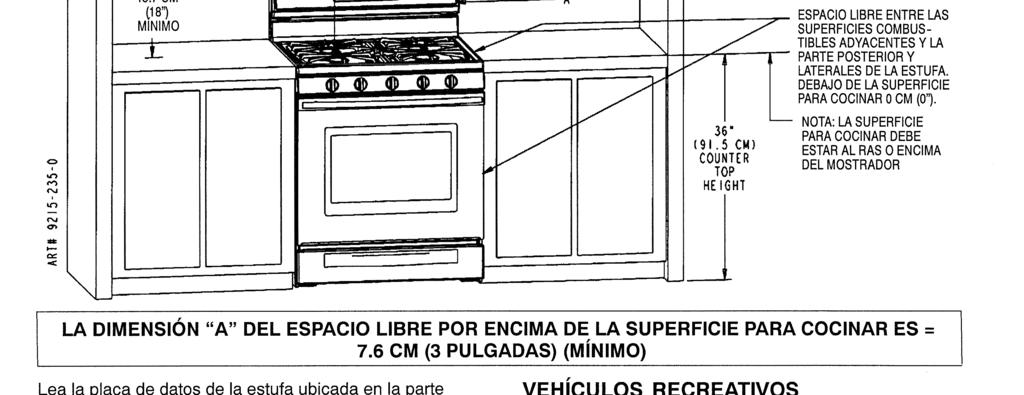
8 INSTALADOR: DEJE ESTAS INSTRUCCIONES CON EL ELECTRODOMÉSTICO MANUAL DE INSTALACIÓN Estufa independiente convencional de 76 cm (30 pulgadas) de ancho CONSERVE ESTE MANUAL COMO REFERENCIA FUTURA EL MANUAL TIENE LA FINALIDAD DE AYUDARLE EN LA INSTALACIÓN Y LOS AJUSTES INICIALES DE LA ESTUFA. ADVERTENCIA ESPECIAL Solamente el personal calificado deberá instalar o dar servicio a esta estufa. Lea las Instrucciones de seguridad en el libro de Uso y cuidado antes de usar la estufa. La instalación, los ajustes, el servicio, el mantenimiento o el uso incorrectos, así como las alteraciones de la estufa pueden causar lesiones graves o daños materiales. ADVERTENCIA TODAS LAS ESTUFAS PUEDEN VOLTEARSE Y CAUSAR LESIONES A LAS PERSONAS. INSTALE LOS DISPOSITIVOS ESTABILIZADORES EMPACA- DOS CON LA ESTUFA. SIGA TODAS LAS INSTRUC- CIONES DE INSTALACIÓN. Su estufa podría no estar equipada con algunas de las características mencionadas en este manual. DIMENSIONES DEL ESPACIO LIBRE La estufa puede instalarse con un espacio libre de cero centímetros adyacente (contra) a la construcción combustible en la parte posterior y en los lados debajo de la superficie para cocinar. Para obtener la información completa relacionada con la instalación de gabinetes de pared encima de la estufa y los espacios libres a las paredes combustibles por encima de la parte superior de la superficie para cocinar, vea los dibujos de instalación. Por MOTIVOS DE SEGURIDAD no instale la estufa en ningún gabinete combustible que no esté de acuerdo con los dibujos de instalación. * NOTA: La dimensión de 76.2 cm (30 ) no puede redu-- cirse a menos de 61 cm (24 ) cuando los gabinetes de pared en una casa están protegidos con materiales contra incendios de acuerdo con las Normas Nacionales Esta-- dounidenses el Código Nacional de Gas Combustible o en casas móviles cuando están protegidas con materiales contra incendios de acuerdo con la Norma Federal para Construcción y Seguridad de Casas Móviles. Para eliminar el riesgo de quemaduras o incendios al atravesarse por encima de las unidades calientes de la superficie, debe evitarse el almacenaje en los gabinetes por encima de las unidades de la superficie. Si se va a proporcionar almacenaje, puede reducirse el riesgo instalando una campana de estufa que sobresalga horizontalmente cuando menos 12.7 cm (5 ) más que los gabinetes inferiores. PRECAUCIÓN: Esta estufa ha sido diseñada de acuerdo con los requisitos de varias agencias de seguridad y cumple con las temperaturas máximas permitidas para los gabinetes de madera de 90 C (194 F). Si esta estufa se instala en gabinetes que tienen una tolerancia más baja a las temperaturas, podría ocurrir decoloración, pérdida del laminado o derretimiento. Póngase en contacto con el servicio de atención al cliente para obtener las dimensiones del gabinete asociado y los accesorios de instalación.
9
10
11 INSTRUCCIONES DE INSTALACIÓN DEL DISPOSITIVO ESTABILIZADOR NOTA: Existe el riesgo de que la estufa se voltee si el electrodoméstico no se instala de acuerdo con las instrucciones de instalación provistas. El uso correcto de este dispositivo reduce el riesgo de VOLTEO. Cuando se use este dispositivo el propietario debe aún observar las precauciones de seguridad según se indican en el MANUAL DE USO Y CUIDADO y evitar usar la puerta del horno o el cajón inferior como banquillo. Se proporcionan las instrucciones para madera y cemento tanto para piso como para pared. Cualquier otro tipo de construcción podría requerir técnicas de instalación especiales según se determine necesario para proporcionar un anclaje adecuado del soporte ESTABILIZADORalpisooalapared. PASO 1 Ubicación del soporte (vea la figura 1) C. Determine la ubicación del borde derecho o izquierdo de la estufa y marque el piso o la pared. D. Coloque el SOPORTE a 2.4 cm (9/16 ) del BORDE marcado hacia el centro del hueco y contra la pared posterior, según se muestra en la figura 1, con el orificio de orientación contra la pared. E. Use el soporte como plantilla y marque los orificios necesarios, según se muestra en la figura 1, para el tipo de construcción que usará. PASO 2 Instalación del soporte estabilizador I. Construcción de madera: 1. Piso: Ubique el centro de los dos orificios que se identifican en la figura 1 como ORIFICIOS PARA EL PISO. Taladre un orificio piloto con una broca de 3 mm (1/8 ) en el centro de cada orificio (puede usar un clavo o un punzón si no tiene un taladro disponible). Asegure el soporte ESTABILIZADOR al piso con los dos tornillos provistos. Continúe con el paso Pared: Ubique el centro de los dos orificios que se identifican en la figura 1 como ORIFICIOS PARA LA PARED. Taladre un orificio piloto en ángulo con una broca de 3 mm (1/8 ) en el centro de cada orificio como se muestra en la figura 2. (Puede usar un clavo o un punzón si no tiene disponible un taladro.) Asegure el soporte ESTABILIZADOR a la pared con los dos tornillos provistos según se muestra en la figura 2. Continúe con el PASO 3. J. Construcción de cemento o concreto: 1. Puede obtenerse tornillos apropiados para la construcción de concreto en una ferretería. Con el taladro haga el orificio del tamaño requerido para el tipo de tornillos que haya obtenido, en el concreto, en el centro de los orificios identificados en la figura 1 como ORIFICIOS PARA EL PISO. Asegure el soporte ESTABILIZADOR al piso. Continúe con el paso 3. PASO 3 Instalación de la estufa A. Por motivos de seguridad así como para obtener el desempeño óptimo, ajuste la estufa de manera que esté bien nivelada y a la altura deseada antes de instalarla en el hueco del gabinete. NOTA: La superficie para cocinar DEBE estar al ras o por encima del mostrador. La nivelación puede revisarse colocando un nivel de burbuja de aire o un recipiente grande con agua en la superficie para cocinar o en la parrilla del horno. Ajuste la estufa ladeándola hacia delante o hacia atrás y girando la pata niveladora según sea necesario. NOTA: Se requiere un espacio libre de cuando menos 6 mm (1/4 ) entre la estufa y la pata niveladora que se enganchará al soporte estabilizador, vea la figura 2. PRECAUCIÓN: La estufa puede dañarse si se mueve o levanta tomándola por la parte superior principal o por el protector posterior o por las asas de la puertas. B. Alinee la estufa en su ubicación final y prepárela para deslizarla hacia atrás en su lugar. Conecte la tubería de gas y enchufe el cordón eléctrico a un tomaco-- rrinte siguiendo las normas indicadas en la conexión y el resto de las instrucciones de instalación. C. Deslice la estufa en su lugar inspeccionando visual-- mente para comprobar que el cordón eléctrico y la tubería de gas estén libremente colocadas y conteni-- das dentro del área ahuecada del panel posterior. D. Para revisar que el soporte estabilizador de la estufa esté bien instalado, use una linterna y vea por debajo de la estufa para comprobar que una de las patas niveladoras esté enganchada en la hendidura del soporte. NOTA: USE CUANDO MENOS DOS (2) TORNILLOS PARA INSTALAR EL SOPORTE ESTABILIZADOR A LA PARED O AL PISO. ORIFICIO DE ORIENTACIÓN ORIFICIOS PARA LA PARED SUJETE EL SOPORTE ESTABILIZADOR CON UN MÍNIMO DE DOS (2) TORNILLOS LARGOSALAPAREDOALPISO. SOPORTE ESTABILIZADOR LOS TORNILLOS DEBEN PENETRAR EN LA MADERA O EL METAL. PLACA DE PARED SOPORTE ESTABILIZADOR ATORNILLE EL SOPORTE A LA PARED DESLICE PARA ASEGURAR FONDO DEL HORNO 6MM (1/4 ) MÍN MM (9/16 ) DEL BORDE DE LA ESTUFA BORDE MARCADO DE LA ESTUFA ORIFICIOS PARA EL PISO (EN CADA LADO) PATA NIVELADORA FIGURA 1 FIGURA
12 CONEXIÓN DE LA ESTUFA Suministro de energía eléctrica El electrodoméstico, cuando se instala, debe conectarse a tierra de acuerdo con los códigos locales o, si no exis-- tieran, con el Código Nacional Eléctrico, ANSI/NFPA 70. En Canadá la estufa debe instalarse de acuerdo con la Norma actual C22.1 de CSA Código Eléctrico Canadiense Parte 1. Conexión del suministro eléctrico La estufa requiere una corriente alterna de 60 ciclos, 120 voltios de un tomacorriente conectado a tierra con un cortacircuitos de 15 amperios. Vea la placa de datos para encontrar la clasificación, que se encuentra ubicada en la superficie inferior del bastidor del frente. Es posible que en ocasiones el usuario experimente desconexiones del circuito si el tomacorriente del interruptor del circuito contra fallas de conexión a tierra (GFCI) o el disyuntor están en uso. ADVERTENCIA Instrucciones eléctricas de conexión a tierra Este electrodoméstico está equipado con una clavija de conexión a tierra (de tres puntas) para protegerlo contra el peligro de descargas eléctricas y debe conectarse directamente en un receptáculo debidamente conectado a tierra. No corte ni quite la punta de conexión a tierra de esta clavija. ADVERTENCIA DESCONECTE EL SUMINISTRO ELÉCTRICO ANTES DE DAR SERVICIO AL ELECTRODOMÉSTICO. Suministro de gas La instalación de esta estufa debe estar en conformidad con los códigos locales o, si no existieran, con la última edición del Código Nacional de Gas Combustible, ANSI Z223.1 En el estado de Massachusetts Este producto debe instalarlo un plomero certificado o un ajustador de gas cuando se instale dentro del estado de Massachusetts. Debe instalarse una válvula manual con asa tipo T en la tubería de suministro de gas al electrodoméstico. Los conectores flexibles de gas, cuando se usen, no deben sobrepasar una longitud de cm (36 pulg). En Canadá la estufa debe instalarse de acuerdo con la Norma actual CAN/CGA--B149 de CGA Códigos de instalación para electrodomésticos y equipos que queman gas y con los códigos locales. ADVERTENCIA Podrían ocurrir fugas de gas en el sistema y causar una situación peligrosa. Las fugas de gas podrían no detectarse sólo por el olor. Los proveedores de gas recomiendan que compre e instale un detector de gas aprobado por UL. Instale y use de acuerdo con las instrucciones del fabricante. Para revisar la presión del sistema de presión de la casa 1. El electrodoméstico y su válvula de cierre individual deben estar desconectados del sistema de suministro de gas durante las pruebas de presión de ese sistema a presiones que sobrepasen 3.5 kpa (1/2 libra por pulgada cuadrada) (35 cm (13.8 pulgadas) de columna de agua). 2. El electrodoméstico debe estar aislado del sistema de suministro de gas cerrando la válvula de cierre individual durante las pruebas de presión de ese sistema a presiones iguales o menores de 3.5 kpa (1/2 libra por pulgada cuadrada) (35 cm (13.8 pulgadas) de columna de agua). Conexión del suministro de gas (vea la figura 3) LA CONEXIÓN DE GAS DEBE REALIZARLA UN TÉCNICO CALIFICADO DE SERVICIO O UN INSTALADOR DE ELECTRODOMÉSTICOS DE GAS. Las pruebas de fugas del electrodoméstico debe realizarlas el instalador de acuerdo con las instrucciones indicadas en la sección h. LA TUBERÍA DE SUMINISTRO DE GAS DEBE TENER UN REGULADOR DE SERVICIO DE GAS NATURAL. LA PRESIÓN DE ENTRADA A ESTE ELECTRODOMÉSTICO DEBE REDUCIRSE A UN MÁXIMO DE 35.5 cm (14 PULGADAS) DE COLUMNA DE AGUA (0.5 LIBRAS POR PULG CUADRADA (PSI). LA TUBERÍA DE SUMINISTRO DE GAS PROPANO/PETRÓLEO LÍQUIDO (LP) DEBE TENER UN REGULADOR DE PRESIÓN DE GAS LP. LA PRESIÓN DE ENTRADA A ESTE ELECTRODOMÉSTICO DEBE REDUCIRSE A UN MÁXIMO DE 35.5 cm (14 PULGADAS) DE COLUMNA DE AGUA (0.5 PSI). LAS PRESIONES DE ENTRADA SUPERIORES A 0.5 PSI PUEDEN DAÑAR EL REGULADOR DE PRESIÓN Y OTROS COMPONENTES DE GAS DEL ELECTRODOMÉSTICO Y PROVOCAR FUGAS DE GAS. NOTA: Esta estufa se embarca de fábrica lista para usarse con gas natural a una presión de cm (4 ) de columna de agua. La presión del suministro de gas para probar el regulador debe ser de cuando menos 2.54 cm (1 ) de presión de columna de agua por encima de la presión del múltiple que se indica en la placa de datos. Si se necesita la conversión a gas LP, convierta el electrodoméstico antes de iniciar la instalación
13 Conexiones recomendadas del suministro de gas TUBERÍA FLEXIBLE DE SUMINISTRO DE ADAPTADOR CASQUILLO ADAPTADOR MACHO DE 1.27 cm (1/2 ) NPT A HEMBRA DE.95 cm (3/8 )NPT REGULADOR ON (encendido) VÁLVULA DE CIERRE DEL REGULADOR CASQUILLO ADAPTADOR MACHO DE 1.27 cm (1/2 ) NPT A HEMBRA DE.95 cm (3/8 )NPT CASQUILLO ADAPTADOR REGULADOR ON (encendido) VÁLVULA DE CIERRE DEL REGULADOR OFF (apagado) FIGURA 3 CODO ROSCADO NPT DE.95 cm (3/8 ) OFF (apagado) TUBERÍA FLEXIBLE DE SUMINISTRO DE ADAPTADOR CUANDO EL INSTALADOR HAYA TERMINADO LA INSTALACIÓN DEL ELECTRODOMÉSTICO, DEJE LA VÁLVULA DE CIERRE DEL REGULADOR DE PRESIÓN EN LA POSICIÓN ABIERTA ON a. DEBE INSTALARSE UNA VÁLVULA DE CIERRE DE GAS EN UN LUGAR ACCESIBLE EN LA TUBERÍA DE SUMINISTRO MÁS ADELANTE DE LA ESTUFA, PARA CERRAR Y ABRIR EL SUMINISTRO DE GAS. Si la estufa se conectará a la tubería de la casa con conectores flexibles o semirrígidos de metal para el electrodoméstico de gas, LAS TUERCAS DE CONEXIÓN NO DEBEN CONECTARSE DIRECTAMENTE EN LAS ROSCAS DE LA TUBERÍA. LOS CONECTORES DEBEN INSTALARSE CON LOS ADAPTADORES PROVISTOS CON EL CONECTOR. b. La tubería de la casa y el conector de la estufa que se use para conectar la estufa al suministro principal de gas, deben estar limpios, sin desechos de metal, sin corrosión, tierra ni líquidos (aceite o agua). La suciedad, etc., en las tuberías de suministro pueden llegar hasta el múltiple de la estufa y causar fallas en las válvulas de gas o en los controles y obstruir los quemadores o los orificios de los pilotos. PRECAUCIÓN: NO LEVANTE NI MUEVA LA ESTUFAPORLASASASDELAPUERTANIPOR EL PROTECTOR POSTERIOR. c. Apague todos los pilotos y la válvula principal de gas de los demás electrodomésticos de gas. d. Cierre la válvula principal de gas en el medidor. e. Antes de conectar la estufa, aplique en todas las roscas compuesto para roscas de tuberías que esté aprobado para de gas LP. f. Use sólo conectores flexibles para conectar la estufa al suministro de gas en el regulador de presión usando los adaptadores provistos con el conector. El regulador provisto con la estufa tiene una conexión hembra de 1.27 cm (1/2 ) NPT. NOTA: Se recomienda que se use un conector flexible certificado por CSA que no sea más largo de 91.4 cm (36 ) con una clasificación mínima de BTU/HR, de acuerdo con los códigos locales. Vea la placa de datos para conocer el tipo de gas para el que se fabricó la estufa. g. Abra la válvula principal de gas al medidor, y vuelva a encender los pilotos de los otros electrodomésticos de gas. h. Aplique un líquido de detección de fugas que sea anticorrosivo en todas las uniones y accesorios de la conexión de gas entre la válvula de cierre de la tubería de suministro y la estufa. Incluya los acce-- sorios y las uniones de gas en la estufa si se alte-- raron las conexiones durante la instalación. Revise si existen fugas! Si aparecen burbujas alrededor de los accesorios y las conexiones significará que hay una fuga. Si aparece una fuga, cierre la válvula de suministro de la tubería de gas, apriete las conexiones, abra la válvula de cierre de la tubería de suministro de gas y vuelva a revisar las fugas. PRECAUCIÓN: NUNCA USE LLAMAS PARA REVISAR SI EXISTEN FUGAS. CUANDO TERMINE DE REVISAR LAS FUGAS, LIMPIE TODOS LOS RESIDUOS.
14 AJUSTES DE LA ESTUFA Sección superior Encendido electrónico Para que funcione, empuje y gire la perilla del quemador superior a la posición de encender LITE. El quemador superior se encenderá. Para APAGAR la chispa después de que se haya encendido el quemador superior, gire la perilla al ajuste alto HI. NOTA: Los quemadores superiores no se ajustan. Obturador de aire Quemador de horneado/asado NOTA: Si no se enciende el quemador, revise la posición de la válvula de cierre del gas del horno en el regulador. a. La longitud aproximada de la llama del quemador del horno es una llama cónica con el interior azul, bien definida de 1.27 cm ( 1/2 ), figura 4. CONVERSIÓN DE GAS CONSULTE LAS INSTRUCCIONES PARA LA CONVERSIÓN DE GAS QUE SE ENCUENTRA EN LA PARTE POSTERIOR DE LA ESTUFA. FIGURA 4 LLAMA CON CONO INTERNO DE 1.27 CM (1/2 ) b. La llama del quemador de horneado/asado puede revisarse de la manera siguiente: 2. Llama amarilla en el quemador abra el obturador de aire del quemador a la posición más abierta que no cause que se apague ni levante la llama cuando el quemador esté frío. (Vea el número 2 de la figura 5.) Las puntas algo amarillentas en el gas LP son normales. 3. Llama azul bien definida pero se levanta -- cierre el obturador de aire hasta el punto en donde no cause que se levante o apague la llama cuando el quemador esté frío. (Vea el número 2 de la figura 5.) OBTURADOR DE AIRE CAMPANA DE ORIFICIO TORNILLO DE SEGURIDAD FIGURA
15 INSTALLATEUR: VEUILLEZ LAISSER CES INSTRUCTIONS AVEC L APPAREIL MANUEL DE MISE EN SERVICE Cuisinière à gaz amovible de 76,2 cm (30 pouces) VEUILLEZ CONSERVER CE MANUEL POUR RÉFÉRENCE ULTÉRIEURE CE MANUEL EST DESTINÉ À FACILITER LA MISE EN SERVICE ET LE RÉGLAGE INITIAUX DE LA CUISINIÈRE. AVERTISSEMENT SPÉCIAL La mise en service et le dépannage de cette cuisinière doivent être réalisés uniquement par du personnel qualifié. Lire les «Mesures de sécurité» dans le manuel de l utilisateur avant de l utiliser. Une mauvaise réalisation de la mise en place, du réglage, de toutes modifications ou réparations ou de l entretien de la cuisinière ou son usage incorrect peuvent entraîner des blessures ou des dégâts graves. AVERTISSEMENT TOUTES LES CUISINIÈRES PEUVENT BASCULER ET PROVOQUER DES BLESSURES. POSER LES DISPOSITIFS DE STABILISATION FOURNIS AVEC CETTE CUISINIÈRE. SUIVRE TOUTES LES CON- SIGNES DE MISE EN SERVICE. Votre cuisinière peut ne pas être dotée de toutes les fonctions mentionnées dans ce manuel. DÉGAGEMENT NÉCESSAIRE La cuisinière peut avoir un dégagement nul (0 po/cm) par rapport aux parois en matériaux combustibles à l arrière et sur les côtés au--dessous de la surface de cuisson (elle peut être contre ces parois). Pour tous renseignements concernant la pose d armoires murales au--dessus de la cuisinière et des dégagements à respecter par rapport aux parois combustibles se trouvant au--dessus de la surface de cuisson, se reporter aux schémas d installation. Pour des RAISONS DE SÉCURITÉ, ne pas monter la cuisinière dans une armoire en matériau combustible non conforme aux schémas d installation. *REMARQUE : La dimension de 76,2 cm (30 po) peut être réduite à 61 cm (24 po) si les armoires murales d un logement sont pro-- tégées par des matériaux ininflammables conformément aux normes American National Standards -- National Fuel Gaz Code ou, dans le cas de maisons mobiles, si les armoires murales sont protégées par des matériaux ininflammables conformément aux règlements du Federal Standard for Mobile Home Construction and Safety. Pour éliminer tout risque de brûlure ou d incendie en essayant d atteindre un objet placé au--dessus d éléments brûlants, éviter d avoir un espace de rangement au--dessus de la surface de cuisson. S il doit y avoir une armoire au--dessus de la table de cuisson, l installation d une hotte dépassant d au moins 13 cm (5 po) de sa partie inférieure réduira les risques liés à ce type d entreposage. ATTENTION : Cette cuisinière satisfait aux règles de divers organismes de protection et aux normes relatives à la température maximum permise de 90 C (194 F) pour les armoires en bois. Si cette cuisinière est adjacente à des armoires pouvant supporter une température inférieure à 90 C (194 5 F) seulement, celles--ci peuvent se décolorer, se délaminer ou fondre. Prenez contact avec le service à la clientèle pour obtenir les dimensions de l armoire et les accessoires d installation.
16

17
18 ANTI-MISE EN PLACE DU SUPPORT DE STABILISATION REMARQUE : La cuisinière risque de basculer si elle n est pas mise en place conformément aux instructions fournies. Si le dispositif de stabilisation est utilisé correctement, il réduit le risque que la cuisinière ne - BASCULE. Même si le dispositif est utilisé correctement, le consommateur doit observer les précautions indiquées dans le MANUEL D UTILISATION ET D ENTRETIEN et éviter d utiliser la porte du four et/ou le tiroir inférieur comme un tabouret. Les instructions sont prévues pour un plancher ou un mur en bois ou en ciment. Un autre matériau pourra requérir des techniques spéciales, qu il conviendra de déterminer, pour assurer la fixation du SUPPORT DE STABILISATION au mur ou au plancher. ÉTAPE 1 - Emplacement du support (voir figure 1) A. Déterminer où le «bord» gauche ou droit de la cuisinière se trouvera une fois celle--ci en place et le marquer d un repère sur le plancher. B. Placer le SUPPORT à 14 mm (9/16 po) de la marque «BORD» en allant vers le centre de l ouverture et contre le mur arrière tel qu indiqué à la figure 1, le trou d orientation étant contre le mur. C. Utiliser le support comme gabarit et marquer l emplacement de tous les trous pour le type de matériau sur lequel le support doit être fixé, tel qu indiqué à la figure 1. ÉTAPE 2 - Pose du support de stabilisation A. Bois : 1. Plancher : Déterminer le centre des deux trous identifiés par «TROUS POUR PLANCHER» à la figure 1. Percer un trou de positionnement de 3 mm (1/8 po) au centre de chaque trou (un clou ou un poinçon peut également être utilisé si une perceuse n est pas disponible). Fixer le support de STABILISATION au plancher à l aide des deux vis fournies. Passer à l ÉTAPE Mur : Déterminer le centre des deux trous identifiés par «TROUS POUR MUR» à la figure 1. Percer un trou de positionnement de 3 mm (1/8 po) au centre de chaque trou (un clou ou un poinçon peut également être utilisé si une perceuse n est pas disponible) tel qu indiqué à la figure 2. Fixer le support de STABILISATION au mur à l aide des deux vis fournies tel qu indiqué à la figure 2. Passer à l ÉTAPE 3. B. Ciment ou béton : 1. On trouve des vis convenant au ciment ou au béton dans les quincailleries. Percer les trous de positionnement de la grandeur correspondant à celle des vis obtenues en quincaillerie au centre des trous identifiés «TROUS POUR PLAN-- CHER» à la figure 1. Fixer le support de STABI-- LISATION au plancher. Passer à l ÉTAPE 3. ÉTAPE 3 - Mise en place de la cuisinière A. Pour des raisons de sécurité et pour obtenir des résultats optimums à la cuisson, régler la cuisinière de façon à ce qu elle soit de niveau et à la hauteur voulue avant de la mettre en place dans l ouverture. REMARQUE : La surface de cuisson DOIT être au même niveau que le comptoir ou légèrement plus haute. Pour vérifier le niveau, mettre un niveau à bulle ou une grande casserole d eau sur la surface de cuisson ou sur la grille du four. Régler le niveau en la basculant vers l avant ou l arrière et en tournant les pieds de mise à niveau autant que nécessaire. REMARQUE : Un dégagement minimum de 6 mm (1/4 po) est exigé entre la cuisinière et le pied de mise à niveau qui va s insérer dans le support de stabilisation (voir figure 2). ATTENTION : La cuisinière peut être abîmée si elle est déplacée et soulevée par le dessus, à l aide du dosseret ou par les poignées de porte. B. Placer la cuisinière de façon à ce qu elle puisse entrer dans l ouverture où elle sera encastrée et se préparer à la pousser en place. Raccorder au gaz et brancher le cordon d alimentation dans la prise en suivant les indications fournies pour le raccordement de la cuisinière et dans le reste des consignes de mise en service. C. Glisser la cuisinière en place en l inspectant visuellement pour s assurer que le cordon d alimentation et la conduite de gaz ne se trouvent pas coincés et qu ils s insèrent dans la partie en creux du panneau arrière. D. Pour vérifier si le support de stabilisation est correctement en place, regarder sous la cuisinière et s assurer qu un des pieds arrière est bien inséré dans la fente du support. REMARQUE: UTILISER UN MINIMUM DE DEUX (2) VIS POUR FIXER LE SUPPORT AU MUR OU AU PLANCHER. 14,5 MM [9/16 PO] DU BORD DE LA CUISINIÈRE REPÈRE DU BORD DE LA CUISINIÈRE TROU D ORIENTATION TROUS POUR MUR TROUS POUR LE PLANCHER (DE CHAQUE CÔTÉ) FIXER LE SUPPORT DE STABILISATION AU PLANCHER OU AU MUR AVEC UN MINIMUM DE DEUX (2) LONGUES VIS. SUPPORT DE STABILISATION PIED DE RÉGLAGE LES VIS DOIVENT PÉNÉTRER DANS LE BOIS OU LE MÉTAL. PLAQUE MURALE SUPPORT DE STABILISATION FIXER LE SUPPORT AU MUR GLISSER DANS LE SUPPORT POUR STABILISER BAS DE LA CUISINIÈRE 6MM (1/4 PO) MIN. FIGURE 1 FIGURE
19 RACCORDEMENT DE LA CUISINIÈRE Alimentation électrique Une fois en place, l appareil doit être relié à la terre conformément aux codes locaux ou, en l absence de codes locaux, aux normes ANSI/NFPA 70 du National Electrical Code. Au Canada, le raccordement de la cuisinière doit être conforme à la norme ACN C22.1 du Code d électricité canadien partie 1. Raccordement à l alimentation électrique La cuisinière exige une alimentation en courant alternatif 120 V et 60 Hz par prise de courant raccordée à la terre et équipée d un disjoncteur de 15 A. Vérifier la puissance électrique de l appareil sur la plaque signalétique, située dans la partie inférieur du bâti avant. L utilisateur pourra occasionnellement avoir des problè-- mes de panne de courant si une prise avec disjoncteur de prise à la terre ou un disjoncteur sont utilisés. AVERTISSEMENT Miseàlaterre Cet appareil est muni d une fiche à trois broches avec mise à la terre pour assurer la protection contre les risques d électrocution et doit être branché directement dans une prise de courant correctement reliée à la terre. Ne pas enlever ni couper la broche de terre de cette fiche électrique. AVERTISSEMENT DÉBRANCHER L APPAREIL DE L ALIMENTATION ÉLECTRIQUE AVANT TOUT DÉPANNAGE. Alimentation en gaz La mise en service de cette cuisinière doit être conforme aux codes locaux ou, en l absence de tels codes, avec la norme ANSI Z223.1, dernière édition, du National Fuel Gas Code. Dans le «Commonwealth of Massachusetts» Ce produit doit être mis en service par un plombier ou un monteur d installations au gaz porteur d une licence pour toute mise en service à l intérieur du «Commonwealth of Massachusetts». Un robinet d arrêt de gaz manuel de type à poignée en T doit être posé sur la conduite de gaz de cet appareil. Un raccord de gaz flexible devra, s il est utilisé, ne pas être d une longueur supérieure à 91,4 cm (3 pi/36 po). Au Canada, la mise en service de la cuisinière doit être conforme à la norme ACG CAN/ACG--B149 en vigueur relative aux codes de mise en service d appareils à gaz et/ou aux codes locaux. AVERTISSEMENT Des fuites de gaz peuvent se produire et aboutir à une situation dangereuse. Les fuites de gaz ne peuvent pas être détectées simplement à l odeur. Les fournisseurs de gaz recommandent d acheter et de poser un détecteur de gaz homologué UL. Le poser et l utiliser conformément aux consignes du fabricant. Vérification de la pression des conduites du logis 1. L appareil à gaz et son robinet d alimentation doivent être désolidarisés des conduites de gaz pendant toute vérification de la pression à des pressions supérieures à 0,5 lb/po 2 /3,5 kpa (13,8 po de colonne d eau). 2. L appareil à gaz doit être coupé des conduites de gaz en fermant son robinet de gaz individuel pendant toute vérification de la pression dans les conduites de gaz à des pressions égales ou inférieures à 0,5 lb/po 2 /3,5 kpa (13,8 po de colonne d eau). Raccordement à l alimentation au gaz de réseau (voir la figure 3) LE RACCORDEMENT AU GAZ DOIT ÊTRE EFFECTUÉ PAR UN TECHNICIEN AYANT REÇU LA FORMATION APPROPRIÉE OU PAR UN INSTALLATEUR D APPAREILS À GAZ. La vérification de l absence de fuites sera effectuée par l installateur conformément aux directives fournies à la section h. LA CONDUITE DE GAZ NATUREL DOIT ÊTRE ÉQUIPÉE D UN DÉTENDEUR POUR GAZ NATUREL. LA PRESSION À L ARRIVÉE DE CET APPAREIL DOIT ÊTRE DÉTENDUE DE FAÇON À NE PAS ÊTRE SUPÉRIEURE À 0,5 LB/PO 2 /3,5KPA(14PODE COLONNE D EAU). LA CONDUITE DE GAZ DE PÉTROLE LIQUÉFIÉ (GPL)/PROPANE DOIT ÊTRE ÉQUIPÉE D UN DÉTENDEUR POUR GPL. LA PRESSION À L ARRIVÉE DE CET APPAREIL DOIT ÊTRE DÉTENDUE DE FAÇON À NE PAS ÊTRE SUPÉRIEURE À 0,5 LB/PO 2 /3,5KPA(14PODE COLONNE D EAU). UNE PRESSION À L ARRIVÉE SUPÉRIEURE À 3,5 KPA (0,5 LB/PO 2 ) PEUT ENDOMMAGER LE DÉTENDEUR DE L APPAREIL ET LES AUTRES COMPOSANTS DE CET APPAREIL ET POURRAIT PROVOQUER DES FUITES DE GAZ. REMARQUE : La cuisinière est réglée au gaz naturel pour une pression de gaz naturel de 1,25 kpa (4 po de colonne d eau) en usine. La pression de gaz nécessaire pour vérifier le détendeur doit être au moins 0,25 kpa (1 po de colonne d eau) au -dessus de la pression de rampe indiquée sur la plaque signalétique. Si la conversion au gaz GPL est nécessaire, convertir l appareil avant la mise en place
20 Raccordement à l alimentation en gaz recommandé CONDUITE D ALIMENTATION FLEXIBLE DE ADAPTATEUR DOUILLE DE RÉDUCTION 1/2 PO NPT MÂLE À 3/8 PO NPT FEMELLE DÉTENDEUR MARCHE DÉTENDEUR ROBINET D ARRÊT ARRÊT DOUILLE DE RÉDUCTION 1/2 PO NPT MÂLE À 3/8 PO NPT FEMELLE DÉTENDEUR MARCHE DÉTENDEUR ROBINET D ARRÊT ARRÊT FIGURE 3 COUDE MÂLE--FEMELLE DE 3/8 PO NPT CONDUITE D ALIMENTATION FLEXIBLE DE ADAPTATEUR UNE FOIS LA MISE EN SERVICE DE LA CUISINIÈRE TERMINÉE PAR L INSTALLATEUR, LAISSER LE ROBINET DU DÉTENDEUR DE L APPAREIL SUR LA POSITION DE «MARCHE». a. UN ROBINET D ARRÊT DEVRA ÊTRE POSÉ DANS UN ENDROIT ACCESSIBLE DE LA CONDUITE DE GAZ EN AMONT DE LA CUISINIÈRE POUR PERMETTRE D OUVRIR ET DE FERMER L ALIMENTATION EN GAZ. Si la cuisinière doit être raccordée à des conduites à l aide de raccords métalliques flexibles ou semi--rigides pour appareils à gaz, LES ÉCROUS DES RACCORDS NE DOIVENT PAS ÊTRE VISSÉS DIRECTEMENT SUR LE FILETAGE DES CONDUITES. LES RACCORDS DOIVENT ÊTRE RACCORDÉS À LA CONDUITE À L AIDE DES ADAPTATEURS FOURNIS. b. La conduite de gaz du logis et/ou le raccord de la cuisinière à gaz utilisés pour raccorder la cuisinière à l alimentation en gaz doivent être propres, libres de toutes rognures de métal, rouille ou saleté et de tout liquide (huile ou eau). La saleté qui se trouve dans les conduites peut se trouver emportée vers la rampe à gaz et entraîner des problèmes au niveau des robinets de gaz ou des commandes et boucher les orifices des brûleurs et/ou des veilleuses. ATTENTION : NE PAS SOULEVER NI DÉPLACER LA CUISINIÈRE EN LA PRENANT PAR LES POIGNÉES DE PORTE OU LE DOSSERET. c. Éteindre toutes les veilleuses et le robinet d arrêt de tous autres appareils à gaz. d. Fermer le gaz au robinet principal du compteur de gaz. e. Avant de raccorder la cuisinière au gaz, enduire tous les filetages de pâte à filetage convenant au GPL. f. Raccorder la cuisinière à l alimentation en gaz au niveau du détendeur uniquement à l aide des adaptateurs fournis avec le raccord. Le détendeur fourni avec la cuisinière est équipé d un raccord femelle de 1/2 po NPT. REMARQUE : Il est recommandé d utiliser un raccord flexible homologué CSA d une longueur maximum de 91,4 cm (36 po) et une puissance nominale minimum de BTU/h, conformément aux codes locaux. Voir sur la plaque signalétique le type de gaz pour lequel la cuisinière est prévue. g. Ouvrir le robinet de gaz au niveau du compteur et rallumer la veilleuse de tous autres appareils à gaz. h. Appliquer du liquide de détection de fuites non corrosif sur tous les joints et raccords entre le robinet de la conduite de gaz et l appareil. Inclure les joints et raccords de l appareil si ceux--ci ont pu se trouver desserrés pendant la mise en service. Vérifier les fuites! Si des bulles apparaissent autour des joints et des raccords, il y a une fuite. En cas de fuite, fermer le robinet d alimentation de gaz, serrer les raccords, puis ouvrir le robinet de gaz et revérifier s il y a des fuites. ATTENTION : NE JAMAIS VÉRIFIER LA PRÉSENCE DE FUITES À L AIDE D UNE FLAMME. UNE FOIS LA VÉRIFICATION DE LA PRÉSENCE DE FUITES TERMINÉE, ESSUYER TOUT RÉSIDU DE PRODUIT
21 RÉGLAGES DE LA CUISINIÈRE Partie supérieure - Allumage électrique Pour allumer un brûleur de la surface de cuisson, pousser sur le bouton de commande correspondant et le mettre sur la position LITE. Le brûleur s allume. Pour CESSER la production d étincelles une fois le brûleur allumé, tourner le bouton sur le réglage HI. REMARQUE : Les brûleurs de la surface de cuisson ne sont pas réglables. Obturateur d air - Brûleur du four et du gril REMARQUE : Si le brûleur du four ne s allume pas, vérifier la position du robinet d arrêt. a. La hauteur approximative de la flamme d un brûleur du four doit présenter une partie bleue distincte de 13 mm (1/2 po) (voir la figure 4). CONVERSION À UN GAZ DIFFÉRENT VOIR LES CONSIGNES DE CONVERSION À UN TYPE DE GAZ DIFFÉRENT À L ARRIÈRE DE LA CUISINIÈRE. FIGURE 4 CÔNE INTÉRIEUR DE LA FLAMME DE 1,3 CM (1/2 PO) b. Pour vérifier la flamme du brûleur du four/gril : 1. Flamme jaune -- ouvrir l obturateur d air afin d assurer son ouverture maximum tout en ayant une flamme qui ne se soulève pas du brûleur ou qui s éteigne lorsque le brûleur est froid. (Voir l élément 2 de la figure 5.) Il est normal que la flamme présente une pointe légèrement jaune avec le GPL. 2. Flamme avec partie bleue distincte mais qui se soulève du brûleur -- fermer l obturateur d air jusqu à ce qu il produise une flamme qui ne se soulève pas du brûleur ou s éteigne lorsque le brûleur est froid. (Voir l élément 2 de la figure 5.) OBTURATEUR D AIR CAPUCHON D ORIFICE VISDEBLOCAGE FIGURE
GUIDE D INSTALLATION PVC CELLULAIRE
 GUIDE D INSTALLATION PVC CELLULAIRE 7 5 3 4 1 2 6 8 NOTES IMPORTANTES Travailler toujours de gauche à droite, de bas en haut. Utiliser des vis en acier inoxidable #8 x 1.5 (3,8 cm) à tous les 16 /40,64
Middle Panel Panneau du milieu Panel medio 1
 A Desktop Dessus de bureau Tapa del escritorio B Left Panel Panneau gauche Costado izquierdo C Middle Panel Panneau du milieu Panel medio D Right Panel Panneau droit Costado derecho E Back Panel Panneau
1. Configurez votre Stick Up Cam Wired dans l application Ring.
 Stick Up Cam Wired 1. Configurez votre Stick Up Cam Wired dans l application Ring. Téléchargez l application Ring. L application vous guide dans la configuration et l utilisation de votre Stick Up Cam
SEALED GAS COOKTOPS JGC WEST FOURTH STREET, NORTH NEWTON, IA 50208
 INSTALLATION MANUAL SEALED GAS COOKTOPS JGC8645 403 WEST FOURTH STREET, NORTH NEWTON, IA 50208 IMPORTANT: Dimensions Shown in Both Inches and Centimeters. IMPORTANT: Be sure the appliance being installed
LP/High Altitude LP/High Altitude Natural Gas Conversion Kit For United States Installations
 LP/High Altitude LP/High Altitude Natural Gas Conversion Kit For United States Installations Installation Instructions For Model Series G Furnaces, P(G,N) Gas/Electric Appliances, and R Gas/Electric Appliances
TC42 CHALET II BURNER KIT INSTALLATION INSTRUCTIONS
 INSTALLER: Leave this manual with the appliance. CONSUMER: Retain this manual for future reference. These instructions are supplementary to the Installation and Operating Instructions supplied with the
Gas Conversion Kits and Instructions
 Gas Conversion Kits and Instructions INSTALLATION FORM RGM 432/433-GC (Version D.1) Obsoletes Form RGM 432/433-GC (Version D) APPLIES TO: Model FT and Model SFT All gas conversion must be done by a qualified
INSTALLATION INSTRUCTIONS FRONT CONTROL FREESTANDING GAS RANGE
 INSTALLATION INSTRUCTIONS FRONT CONTROL FREESTANDING GAS RANGE INSTALLATION AND SERVICE MUST BE PERFORMED BY A QUALIFIED INSTALLER. IMPORTANT: SAVE FOR LOCAL ELECTRICAL INSPECTOR'S USE. READ AND SAVE THESE
kurt versen INSTALLATION INSTRUCTIONS-L342/4/6 SURFACE MOUNTED LED SQUARE CYLINDER
 INSTALLATION INSTRUCTIONS-L342/4/6 SURFACE MOUNTED LED SQUARE CYLINDER MODEL: 1100/1500/2100 LUMEN : L342/4/6 (WIDE, MEDIUM, & NARROW DISTRIBUTION) Fig. 1 MOUNTING YOKE J-BOX (BY OTHERS) HOUSING J-BOX
Roll Up 28. Ref A. DE Anleitung FR Notice ES Manual PT Instruções PL Instrukcja RU Руководство CS Návod
 Roll Up 28 WT Ref. 5122117A DE Anleitung FR Notice ES Manual PT Instruções PL Instrukcja RU Руководство CS Návod Copyright 2013 Somfy SAS. All rights reserved - V1-02/2013 1 Sommaire 1. Informations préalables
TC30 BLACK DIAMOND BURNER KIT INSTRUCTIONS
 IMPORTANT: THESE INSTRUCTIONS ARE TO REMAIN WITH THE HOMEOWNER These instructions are supplementary to the Installation and Operating Instructions supplied with the fi replace and should be kept together.
TG 304 (IX) GH NA TG 365 (IX) GH NA. Installation Instructions. Instructions d Installation. Intrucciones de Installación
 GH NA TG 365 (IX) GH NA. Installation Instructions. Instructions d Installation. Intrucciones de Installación") EN English 3 FR Français 21 ES Español 39 Installation Instructions Instructions d Installation Intrucciones de Installación GAS COOKTOP TABLE GAZ ENCIMERA DE GAS TG 304 (IX) GH NA TG 365 (IX) GH NA 2
EN English 3 FR Français 21 ES Español 39 Installation Instructions Instructions d Installation Intrucciones de Installación GAS COOKTOP TABLE GAZ ENCIMERA DE GAS TG 304 (IX) GH NA TG 365 (IX) GH NA 2
TCWS.54NG03C2 BLACK DIAMOND BURNER KIT INSTRUCTIONS
 IMPORTANT: THESE INSTRUCTIONS ARE TO REMAIN WITH THE HOMEOWNER These instructions are supplementary to the Installation and Operating Instructions supplied with the fi replace and should be kept together.
PRO-RANGE FULL GAS INSTALLATION INSTRUCTIONS INSTRUCTIONS D INSTALLATION INSTRUCCIONES PARA LA INSTALACIÓN
 PRO-RANGE 30-36 FULL GAS INSTALLATION INSTRUCTIONS INSTRUCTIONS D INSTALLATION INSTRUCCIONES PARA LA INSTALACIÓN Dear Customer, Thank you for purchasing one of our Sofia ranges. This range was conceived,
Installation Instructions Free-Standing and Front Control Electric Ranges
 Installation Instructions Free-Standing and Front Control Electric Ranges BEFORE YOU BEGIN Read these instructions completely and carefully. IMPORTANT Save these instructions for local inspector s use.
30" GAS SLIDE-IN RANGE INSTALLATION INSTRUCTIONS (Models with Sealed Top Burners)
") 30" GAS SLIDE-IN RANGE INSTALLATION INSTRUCTIONS (Models with Sealed Top Burners) INSTALLATION AND SERVICE MUST BE PERFORMED BY A QUALIFIED INSTALLER. IMPORTANT: SAVE FOR LOCAL ELECTRICAL INSPECTOR'S USE.
30" GAS SLIDE-IN RANGE INSTALLATION INSTRUCTIONS (Models with Sealed Top Burners) INSTALLATION AND SERVICE MUST BE PERFORMED BY A QUALIFIED INSTALLER. IMPORTANT: SAVE FOR LOCAL ELECTRICAL INSPECTOR'S USE.
TC42 TRANQUILITY BURNER KIT INSTRUCTIONS
 IMPORTANT: THESE INSTRUCTIONS ARE TO REMAIN WITH THE HOMEOWNER These instructions are supplementary to the Installation and Operating Instructions supplied with the fi replace and should be kept together.
INSTALLER: LEAVE THESE INSTRUCTIONS WITH THE APPLIANCE INSTALLATION MANUAL. Gas 24-inch Built-In Ovens PLEASE KEEP THIS MANUAL FOR FUTURE REFERENCE
 INSTALLER: LEAVE THESE INSTRUCTIONS WITH THE APPLIANCE INSTALLATION MANUAL Gas 24-inch Built-In Ovens PLEASE KEEP THIS MANUAL FOR FUTURE REFERENCE THE MANUAL IS INTENDED TO ASSIST IN THE INITIAL INSTALLATION
TC36 SEE-THRU CHALET BURNER KIT INSTRUCTIONS
 IMPORTANT: THESE INSTRUCTIONS ARE TO REMAIN WITH THE HOMEOWNER These instructions are supplementary to the Installation and Operating Instructions supplied with the fi replace and should be kept together.
Instructions for Converting Range to Operate on Liquefied Petroleum Gas
 INSTALLATION AND SERVICES MUST BE PERFORMED BY A QUALIFIED INSTALLER IMPORTANT: SAVE INSTRUCTION MANUAL FOR THE LOCAL INSPECTOR S USE. READ AND SAVE THESE INSTRUCTIONS FOR FUTURE REFERENCE This conversion
TC42 CHALET BURNER KIT INSTALLATION INSTRUCTIONS
 INSTALLER: Leave this manual with the appliance. CONSUMER: Retain this manual for future reference. These instructions are supplementary to the Installation and Operating Instructions supplied with the
FITTING INSTRUCTIONS FOR CP0368BL AERO CRASH PROTECTORS DUCATI MONSTER
 FITTING INSTRUCTIONS FOR CP0368BL AERO CRASH PROTECTORS DUCATI MONSTER 1200 14- Picture A Picture B THIS KIT CONTAINS THE ITEMS PICTURED AND LABELLED BELOW. DO NOT PROCEED UNTIL YOU ARE SURE ALL PARTS
Electric 30-inch Wide Free-standing Double Oven Range
 INSTALLER: LEAVE THESE INSTRUCTIONS WITH THE APPLIANCE INSTALLATION MANUAL Electric 30-inch Wide Free-standing Double Oven Range PLEASE KEEP THIS MANUAL FOR FUTURE REFERENCE THE MANUAL IS INTENDED TO ASSIST
Installation Instructions
 Instructions et instruction e instrucción Dual-F uel Slide-In Range fr es Cuisinièr e mixt e El combus tible doble liber ta las gamas paradas Table of Contents Safety.....................................................
2015 The Outdoor Plus
 2015 The Outdoor Plus Safety Instructions... 3 Gas Requirements... 5 Liquid Propane... 5 Natural Gas... 7 Set-Up... 8 1. Place the fire pit in a desired location.... 9 2. Connect the gas line... 11 3.
Installation Instructions Electric Slide-In Ranges
 Installation Instructions Electric Slide-In Ranges 2 PREPARE THE OPENING (FOR INDOOR USE ONLY) See illustrations for all rough-in and spacing dimensions. The range may be placed with 0 clearance (flush)
INSTALL/REMOVAL INSTRUCTIONS: EVAP CANISTER VENT VALVE
 REMOVAL/INSTALL OF EVAP CANISTER VENT VALVE 2008 1999 Chevrolet Silverado, 2008 1999 GMC Sierra INSTALACIÓN/EXTRACCIÓN DE VÁLVULA DE VENTILACIÓN DEL RECIPIENTE EVAP 2008 1999 Chevrolet Silverado, 2008
2 PREPARE THE OPENING (FOR INDOOR USE ONLY)
") Installation Instructions Free-Standing and Front Control Electric Ranges Questions? Call 1.800.GE.CARES (1.800.432.2737) or visit www.geappliances.com In Canada, call 1.800.561.3344 or visit www.geappliances.ca
Installation Instructions Free-Standing and Front Control Electric Ranges Questions? Call 1.800.GE.CARES (1.800.432.2737) or visit www.geappliances.com In Canada, call 1.800.561.3344 or visit www.geappliances.ca
Household Appliances Over-the-Range Microwave
 Household Appliances Over-the-Range Microwave Installation Instructions For Models: HMV9302, HMV9303, HMV9305, HMV9306, HMV9307 PLEASE READ ENTIRE INSTRUCTIONS BEFORE PROCEEDING IMPORTANT: Save these instructions
TC36 CHALET II BURNER KIT INSTALLATION INSTRUCTIONS
 INSTALLER: Leave this manual with the appliance. CONSUMER: Retain this manual for future reference. These instructions are supplementary to the Installation and Operating Instructions supplied with the
RD903612A. Figure / Figura A SEE / VOIR / VEA FIG. C FIG. B FIG. D
 RD0A Figure / Figura A 5 0 SEE / VOIR / VEA FIG. C SEE / VOIR / VEA FIG. B 5 0 5 5 55 5 5 5 5 5 5 5 5 55 55 5 5 0 5 5 SEE / VOIR / VEA FIG. D 50 0 5 55 5 5 RD0A Figure / Figura A KEY P/N DESCRIPTION QTY
WE5910S01. 30" Acero Inoxidable. Capacidad Color. Especificaciónes. Whirlpool Mexico S.A de C.V. 1/13 JAS
 Especificaciónes Whirlpool Mexico S.A de C.V. 1/13 JAS Cubierta, Quemadores, Parrillas, Panel s Whirlpool Mexico S.A de C.V. 2/13 JAS Descripción Cubierta, Quemadores, Parrillas, Panel s C a Numero de
TC36 CHALET BURNER KIT INSTALLATION INSTRUCTIONS
 INSTALLER: Leave this manual with the appliance. CONSUMER: Retain this manual for future reference. These instructions are supplementary to the Installation and Operating Instructions supplied with the
Index. TerraPorte 7600 & accessable
 TerraPorte 7600 & accessable Out-Swing / Ouverture Extérieure Thermally broken frame with superior air / water performance. Rain screen design and multi-point locking ideal for residential and condominium
GRLP4 CONVERSION KiT APPLiCATiON instructions
 GRLP4 CONVERSION KiT APPLiCATiON instructions INSTALLATION AND SERVICE MUST BE PERFORMED BY A QUALIFIED INSTALLER. IMPORTANT: SAVE FOR LOCAL ELECTRICAL INSPECTOR'S USE. READ AND SAVE THESE INSTRUCTIONS
, & Series Nested Hardware
 RECORD THIS INFORMATION FOR FUTURE REFERENCE BEFORE INSTALLING THE UNIT: Model Number Serial Number Date Purchased Place of Purchase USA SERVICE OFFICE Dometic Corp. 509 So. Poplar St. LaGrange, IN 46761
30" ELECTRIC SLIDE-IN RANGE INSTALLATION INSTRUCTIONS
 30" ELECTRIC SLIDE-IN RANGE INSTALLATION INSTRUCTIONS INSTALLATION AND SERVICE MUST BE PERFORMED BY A QUALIFIED INSTALLER. IMPORTANT: SAVE FOR LOCAL ELECTRICAL INSPECTOR'S USE. READ AND SAVE THESE INSTRUCTIONS
ThermaWall XTRM2600 Unitized Curtain Wall
 ThermaWall XTRM2600 Unitized Curtain Wall Unitized thermally broken curtain wall - Capped and SSG, 2 1/2" (63.5mm) and 3" (76.2mm) profile widths, various system depths. Mur-rideau à bris thermique unitisé
TC30 HEARTWOOD BURNER INSTALLATION INSTRUCTIONS
 INSTALLER: Leave this manual with the appliance. CONSUMER: Retain this manual for future reference. These instructions are supplementary to the Installation and Operating Instructions supplied with the
Apliques A BL
 Apliques A06 23 30 BL 45 Apliques A06 23 30 BL Apliques A06 14 30 Ne, A06 23 30 BL 48 LUMIK. IP40 Rectangular y estilizada. Gracias a su delicada luz esta luminaria de diseño sobrio envuelve los espacios
ASSEMBLY GUIDE. Customer Service: INCH² 2-BURNER & 864 INCH² 2-BURNER
 ASSEMBLY GUIDE 688 INCH² 2-BURNER & 864 INCH² 2-BURNER DANGER If you smell gas: 1. Shut off gas to the appliance. 2. Extinguish any open flames. 3. Open lid. 4. If odor continues, keep away from the appliance
MASTERPIECE SERIES GAS COOKTOPS
 MASTERPIECE SERIES GAS COOKTOPS MASTERPIECE SERIES GAS COOKTOPS Model: SGS SGSX SGSL Table of Contents Safety......................................1 IMPORTANT SAFETY INSTRUCTIONS..............................
CONVERSION INSTRUCTIONS
 CONVERSION INSTRUCTIONS Natural Gas to Propane Gas Conversion Kit For Thermador Professional Cooktops and Ranges Model STARLPKIT Part No. 35-00-682 Contains 7mm Hex Main Orifices This kit is used to convert
Instructions for Converting Range to Operate on Liquefied Petroleum Gas
 INSTALLATION AND SERVICES MUST BE PERFORMED BY A QUALIFIED INSTALLER IMPORTANT: SAVE INSTRUCTION MANUAL FOR THE LOCAL INSPECTOR S USE. READ AND SAVE THESE INSTRUCTIONS FOR FUTURE REFERENCE This conversion
INSTALLER: LEAVE THESE INSTRUCTIONS WITH THE APPLIANCE. Electric 30-inch Wide
 INSTALLER: LEAVE THESE INSTRUCTIONS WITH THE APPLIANCE IN ON MANUAl Electric 30-inch Wide Free-stand" e PLEASE KEEP THIS MANUAL FOR FUTURE REFERENCE THE MANUAL IS INTENDED TO ASSIST IN THE INITIAL INSTALLATION
TC36 SEE-THRU LODGEWOOD BURNER AND PANEL KIT INSTRUCTIONS
 IMPORTANT: THESE INSTRUCTIONS ARE TO REMAIN WITH THE HOMEOWNER These instructions are supplementary to the Installation and Operating Instructions supplied with the fi replace and should be kept together.
CG CA. Gaggenau Installation instructions Instructions d installation Instrucciones de instalación
 Gaggenau Installation instructions Instructions d installation Instrucciones de instalación CG 280 210CA Gas cooktop Table de cuisson gaz Encimera a gas Table of Contents IMPORTANT SAFETY INSTRUCTIONS
WARNING IMPORTANT. C11810, C11811, C11812, C11813 Sedona Fire Table NG Conversion Kit SAVE THESE INSTRUCTIONS
 C11810, C11811, C11812, C11813 Sedona Fire Table NG Conversion Kit C! US IMPORTANT SAVE THESE INSTRUCTIONS! DANGER If you smell gas: 1. Shut off gas to the appliance. 2. Extinguish any open flame. 3. If
TCWS54 BLACK DIAMOND BURNER KIT INSTRUCTIONS
 INSTALLER: Leave this manual with the appliance. CONSUMER: Retain this manual for future reference. These instructions are supplementary to the Installation and Operating Instructions supplied with the
Installation Guide. Vibracoustic Bath E
 Installation Guide Vibracoustic Bath Retain serial number for reference: Conserver le numéro de série pour référence: Guarde el número de serie para referencia: Français, page Français-1 Español, página
Index. TerraPorte 7600 & accessable
 TerraPorte 7600 & accessable Out-Swing / Ouverture Extérieure Thermally broken frame with superior air / water performance. Rain screen design and multi-point locking ideal for residential and condominium
ASSEMBLY GUIDE. Customer Service: INCH² 3-BURNER & 545 INCH² 3-BURNER
 ASSEMBLY GUIDE 455 INCH² 3-BURNER & 545 INCH² 3-BURNER DANGER If you smell gas: 1. Shut off gas to the appliance. 2. Extinguish any open flames. 3. Open lid. 4. If odor continues, keep away from the appliance
RT2N Thermostat compact
 aractéristiques Excellente répétabilité Réglage de l'écart pour la régulation orrection de l'écart pour le contrôle et l'alarme Résistant à la surpression accidentelle Léger pplications Équipement de sécurité
Installation Instructions
 HOME APPLIANCES Installation Instructions Part No. 9752179 WARNING Injury Hazard Injury from ranges tipping could result. See Installation Instructions. IMPORTANT: Read and save these instructions. IMPORTANT:
FITTING INSTRUCTIONS FOR CP0364BL AERO CRASH PROTECTORS TRIUMPH TIGER 800 / 800XC 11-
 FITTING INSTRUCTIONS FOR CP0364BL AERO CRASH PROTECTORS TRIUMPH TIGER 800 / 800XC 11- Picture A Picture B THIS KIT CONTAINS THE ITEMS PICTURED AND LABELLED BELOW. DO NOT PROCEED UNTIL YOU ARE SURE ALL
Proyectores P NE
 Proyectores P05 01 36 NE 91 Proyectores P05 01 36 NE 92 LUMIK. IP20 Base circular y cuerpo tubular. Este proyector montado en superficie es compacto y potente, a la vez que discreto y de líneas limpias.
TCWS54 SEE THRU DIAMOND BURNER INSTALLATION KIT INSTRUCTIONS
 INSTALLER: Leave this manual with the appliance. CONSUMER: Retain this manual for future reference. These instructions are supplementary to the Installation and Operating Instructions supplied with the
30" ELECTRIC SLIDE-IN RANGE INSTALLATION INSTRUCTIONS
 30" ELECTRIC SLIDE-IN RANGE INSTALLATION INSTRUCTIONS INSTALLATION AND SERVICE MUST BE PERFORMED BY A QUALIFIED INSTALLER. IMPORTANT: SAVE FOR LOCAL ELECTRICAL INSPECTOR'S USE. READ AND SAVE THESE INSTRUCTIONS
Thermostatic Griddle Field Service Kit Instructions
 Thermostatic Griddle Field Service Kit Instructions The following document provides instructions on how to install a Garland Thermostatic Griddle Field Kit and is applicable to each 2 section of a Garland
36-INCH FREE- STANDING GAS RANGE. Model No. PLGF659E F50S2
 " Product No. 30857636F50S2 Series 36" f/s gas Color stainless Market North America Wiring Diagram 318045813 Owner's Guide 318200763 Installation Instructions 318201760 Service Data Sheet 318127026 Timer
INSTALLATION AND OPERATIONS GUIDE FOR GRAND CANYON GAS JUMBO/JUMBO SLIMLINE LOG SYSTEMS
 Burner Systems: JUMBOSLIMBRNR-24 JUMBOSLIMBRNR-30 JUMBOBRNR-36 / JUMBOSLIMBRNR-36 JUMBOBRNR-42 / JUMBOSLIMBRNR-42 JUMBOBRNR-48 / JUMBOSLIMBRNR-48 JUMBOBRNR-60 / JUMBOSLIMBRNR-60 INSTALLATION AND OPERATIONS
P10SC01 900x2000 MANUEL D INSTALLATION / INSTALLATION MANUAL. 80"(2030mm) 78 3/4"(2000mm)
 78 3/4(2000mm)") Update: 000 P0SC0 900x000 ( /"~ ") (8.mm~8.mm) Le micro film protecteur formé lors de son application,fera perler l'eau sur le verre afin d'en faciliter l'entretien. II est recommandé de passer la raclette
Update: 000 P0SC0 900x000 ( /"~ ") (8.mm~8.mm) Le micro film protecteur formé lors de son application,fera perler l'eau sur le verre afin d'en faciliter l'entretien. II est recommandé de passer la raclette
Thermographie, pourquoi l utiliser?
 Thermographie, pourquoi l utiliser? Manny Alsaid FLIR Systems Jacques Wagner MultiPro Plus = 3,600 Thermomètre IR Thermometre IR La zone de mesure Distance au cible Ce quoi l infrarouge? Voir la réalité
Style # Laguna Propane Tank Cover Owner s Manual
 Style # 26100117 Laguna Propane Tank Cover Owner s Manual Warning: For outdoor use only DO NOT use for cooking DO NOT use under any overhead enclosure Manufactured as Model # 6561 in China for: Restoration
FITTING INSTRUCTIONS FOR LP0186BK LICENCE PLATE BRACKET KAWASAKI VULCAN S 15-
 FITTING INSTRUCTIONS FOR LP0186BK LICENCE PLATE BRACKET KAWASAKI VULCAN S 15- THIS KIT CONTAINS THE ITEMS PICTURED AND LABELLED BELOW. DO NOT PROCEED UNTIL YOU ARE SURE ALL PARTS ARE PRESENT. Please note
HOLA SAFETY RING PLAN
 FRENCH VERSION ON PAGE 3 HOLA SAFETY RING PLAN PRICE: $50.00 per person EFFECTIVE FEBRUARY 01, 2019 The Hola Safety Ring Plan allows you to cancel your trip with a refund up to 3 days before departure
AMPLIFICADOR PARA MÁSTIL AMPLIFIER FOR MAST AMPLIFICATEUR POUR MÂT CÓDIGOCODECODE MODELOMODELMODELE 900 AM AM AM07 Número de entradas
 AMPLIFICADORES PARA MÁSTIL Y ALIMENTADORES AMPLIFIERS FOR MAST AND POWER SUPPLIES AMPLIFICATEURS POUR MÂT ET ALIMENTATIONS SERIE 903 SERIES AMPLIFICADOR PARA MÁSTIL AMPLIFIER FOR MAST AMPLIFICATEUR POUR
INS #Shaper IL525013N WARNING WARNING WARNING WARNING WARNING
 IL525013N INS #Shaper Make Certain Power is OFF before starting installation or attempting any maintenance. Risk of Fire/Electric Shock. If not qualified, consult an electrician. Risk of Electric Shock
PRD486WDHU 48-INCH DUAL-FUEL PRO HARMONY RANGE WITH GRIDDLE PROFESSIONAL SERIES, STANDARD-DEPTH, PORCELAIN COOKTOP SURFACE RANGETOP
 RANGETOP 1 3 6 5 2 4 7 FEATURES & BENEFITS - The Star Burner delivers superior flame spread for more even heating - ExtraLow, the widest simmer temperature control as low as 100 F - Superfast 2.5-hour
TCWS.38NG03.C BLACK DIAMOND BURNER KIT INSTRUCTIONS
 IMPORTANT: THESE INSTRUCTIONS ARE TO REMAIN WITH THE HOMEOWNER These instructions are supplementary to the Installation and Operating Instructions supplied with the fireplace and should be kept together.
INSTALLATION INSTRUCTIONS 30" ELECTRIC SLIDE-IN RANGE
 INSTALLATION INSTRUCTIONS 30" ELECTRIC SLIDE-IN RANGE INSTALLATION AND SERVICE MUST BE PERFORMED BY A QUALIFIED INSTALLER. IMPORTANT: SAVE FOR LOCAL ELECTRICAL INSPECTOR'S USE. READ AND SAVE THESE INSTRUCTIONS
INDOOR COOKING. Radiant Cooktop. Installation Manual
 INDOOR COOKING Radiant Cooktop KEC Installation Manual IF THE INFORMATION IN THIS MANUAL IS NOT FOLLOWED EXACTLY, A FIRE OR EXPLOSION MAY RESULT CAUSING PROPERTY DAMAGE, PERSONAL INJURY, OR DEATH. Do not
INSTRUCTIONS D INSTALLATION
 INSTRUCTIONS D INSTALLATION Cossu MC s à montage mural, tà colonne et en surface Nous vous remercions d avoir choisi la marque DXV. Afin de vous assurer que le produit est installé correctement, veuillez
DDS Series IMPORTANT SAFEGUARDS READ AND FOLLOW ALL SAFETY INSTRUCTIONS SAVE THESE INSTRUCTIONS FOR FUTURE REFERENCE. LED Disk Light TO INSTALL:
 DDS Series LED Disk Light IMPORTANT SAFEGUARDS When using electrical equipment, basic safety precautions should always be followed including the following. READ AND FOLLOW ALL SAFETY INSTRUCTIONS DANGER-
Installation Instructions
 Installation Instructions 36 Vent Hood ZV750, ZV755 Hotte Aspirante 36 po Instructions d installation La section française commence à la page 19 Campana de ventilación de 36 Instrucciones de instalación
Chevrolet Impala Grille Replacement - Front Lower
 Chevrolet Impala Kit: Contents Quantity Lower Grille... Required Tools: Flathead Screwdriver 7mm, 0mm Socket J 39544-KIT Complete Torque Socket Set 0 pieces Fastener Caution: Caution: Use the correct fastener
TUBULAR BURNER CONVERSION KIT AGCK-TBXX / AECK-UBXX
 TUBULAR BURNER CONVERSION KIT AGCK-TBXX / AECK-UBXX IMPORTANT - READ ALL INSTRUCTIONS BEFORE YOU BEGIN THE INSTRUCTIONS HEREIN SHOULD BE PERFORMED BY A QUALIFIED SERVICE TECHNICIAN. THE GRILL MUST BE COMPLETELY
I We reserve the right to modify or attar Instructions. No modification or
 INSTALLATION INSTRUCTION VLFS3265 Floor Stand TV Mobile Cart For TV panels: 32"-65" Maximum load capacity: 100 lbs/ 45.5 kg AV shelf max load: 10 lbs/ 4.5 kg Video tray max load: 10 lbs/ 4.5 kg VESA: 100x100-600x400mm
MODEL DCC DOUBLE WALL CHIMNEY CONNECTOR
 Installation & Maintenance LISTED Tested to *UL 103HT & ULC-S641 Instructions MODEL DCC DOUBLE WALL CHIMNEY CONNECTOR A MAJOR CAUSE OF CHIMNEY RELATED FIRES IS FAILURE TO MAINTAIN REQUIRED CLEARANCES (AIR
WET LOCATION INSTALL INSTALACIÓN DE LUGARES HÚMEDOS EMPLACEMENT HUMIDE INSTALLER. Max Continuous Run: 30ft
 SUPER 1 This product must be installed in accordance with the applicable installation code, by a person familiar with the construction and operation of the product and the hazards involved. Ensure power
Assembly/Installation/Use Instructions:
 IMPORTANT We highly recommend that our products be installed and serviced by professionals who are certified in the U.S. by NFI (National Fireplace Institute) or in Canada by WETT (Wood Energy Technical
Installation Instructions
 Installation Instructions 30 Chimney Vent Hood For Model: ZV830 30 (76,2 cm) Hotte aspirante Instructions d installation Pour la Modèle : ZV830 La section française commence à la page 21 Campana de ventilación
! IMPORTANT! SAVE THESE INSTRUCTIONS
 Lot: P.O.! IMPORTANT! SAVE THESE INSTRUCTIONS! WARNING For outdoor use only. DO NOT use for cooking. DO NOT use under any overhead enclosure. C US T9650 LP Square Fire Table Owner s Manual! DANGER If you
MODEL DCC DOUBLE WALL CHIMNEY CONNECTOR
 Installation & Maintenance LISTED Tested to *UL 103HT & ULC-S641 Instructions MODEL DCC DOUBLE WALL CHIMNEY CONNECTOR A MAJOR CAUSE OF CHIMNEY RELATED FIRES IS FAILURE TO MAINTAIN REQUIRED CLEARANCES (AIR
Installation Instructions
 Installation Instructions Dual-Fuel Slide-In Range Notice d'installation Surface de cuisson à bi-combustible INSTRUCCIONES DE INSTALACIÓN Estufa deslizante de doble combustible Table of content Important
INSTALLATION MANUAL For THERMADOR PROFESSIONAL PRO GRAND Dual Fuel Ranges
 INSTALLATION MANUAL For THERMADOR PROFESSIONAL PRO GRAND Dual Fuel Ranges MANUEL D'INSTALLATION Pour cuisinières mixtes PROFESSIONAL PRO GRAND mc de THERMADOR Models/ Modèles/ Modelos: PRD36 PRD48 MANUAL
PRD366GHU 36-INCH DUAL-FUEL PRO HARMONY RANGE PROFESSIONAL SERIES, STANDARD-DEPTH, PORCELAIN COOKTOP SURFACE
 FEATURES & BENEFITS - Exclusive, patented Star Burner most even heating, unsurpassed flame coverage - QuickClean Base designed for easy surface cleaning - Precision simmering capabilities as low as 100
Operator's Manual. Model: RY10MK-PRO MPN: RA-MLT Gallon Direct Fire Melter Kettle Burner Model with Adjustable Flame-Out Valve
 Operator's Manual Model: RY10MK-PRO MPN: RA-MLT-0009 10 Gallon Direct Fire Melter Kettle Burner Model with Adjustable Flame-Out Valve U.S. Patent No. 9,739,021 For Technical Support Please Visit www.rynoworx.com
Genesis. Side Burner Accessory Installation. Step 3. Step 1. Step 2. For use with Genesis Gas Barbecues Only
 Genesis Side Burner Accessory Installation For use with Genesis Gas Barbecues Only Step 1 WARNING: All gas controls and supply valves should be in the OFF position. You will need: Side burner assembly
Installation Instructions
 Installation Instructions Island Vent Hood ZV850, ZV855 Hotte Aspirante Îlot Instructions d installation La section française commence à la page 22 Campana de ventilación en isla Instrucciones de instalación
DRY/DAMP LOCATION INSTALL INSTALACIÓN DE LUGARES SECOS/HÚMEDOS INSTALLATION EMPLACEMENT SEC/HUMIDE. Max Continuous Run: See Section 12
 1 This product must be installed in accordance with the applicable installation code, by a person familiar with the construction and operation of the product and the hazards involved. Ensure power is off
NATURAL GAS CONVERSION KIT
 Model #: 85-2261-4 / G501-0057-03 NATURAL GAS CONVERSION KIT ONLY Compatible with barbecues that bear this SYMBOL: 04-14-17 FOR YOUR SAFETY CAUTION: Read and follow all safety statements, assembly instructions,
Table of Contents/Table des matières. IMPORTANT: Save for local electrical inspector's use.
 INSTLLTION INSTRUTIONS 30" (76.2 M) ELETRI SINGLE N OULE UILT-IN OVEN INSTRUTIONS INSTLLTION ES FOURS ENSTRÉS SIMPLE ET OULE E 30 PO (76,2 M) UILT-IN OVEN SFETY...2 INSTLLTION REQUIREMENTS...2 Tools and
Installation Instructions
 Installation Instructions Custom Hood Inserts Hotte Encastrable sur Mesure Instructions d installation La section française commence à la page 23 Encastres de campana a medida Instrucciones de instalación
Installer: Leave This Manual with Consumer Consumer: Save this Manual for Future Reference
 California Outdoor Concepts, Inc. 17671 Irvine Blvd., Suite 108 Tustin, CA 92780 Telephone 877-274-6773 Fax 877-274-0017 Monterey, Tradewinds Elegant, Carmel OWNER S MANUAL Del Mar, Palm OUTDOOR LIVING
Installation Guide. LPKPDR - Universal LP Conversion Kit for Professional & Designer Ranges/Rangetops. Viking Range, LLC.
 Installation Guide Viking Range, LLC 111 Front Street Greenwood, Mississippi 38930 USA (662) 455-1200 For product information, call 1-888-845-4641 LPKPDR - Universal LP Conversion Kit for Professional
ELECTRIC COOKTOP INSTALLATION INSTRUCTIONS
 ELECTRIC COOKTOP INSTALLATION INSTRUCTIONS INSTALLATION AND SERVICE MUST BE PERFORMED BY A QUALIFIED INSTALLER. IMPORTANT: SAVE FOR LOCAL ELECTRICAL INSPECTOR'S USE. READ AND SAVE THESE INSTRUCTIONS FOR
DRY/DAMP LOCATION INSTALL INSTALACIÓN DE LUGARES SECO/HÚMEDOS INSTALLATION EMPLACEMENT SEC/HUMIDE. Max Continuous Run: /10 (10m)
") 1 This product must be installed in accordance with the applicable installation code, by a person familiar with the construction and operation of the product and the hazards involved. Ensure power is off
1 This product must be installed in accordance with the applicable installation code, by a person familiar with the construction and operation of the product and the hazards involved. Ensure power is off
BUILT-IN OVEN SAFETY
 UILT-IN OVN SFTY Your safety and the safety of others are very important. We have provided many important safety messages in this manual and on your appliance. lways read and obey all safety messages.