tritontools.com Dual Mode Precision Plunge Router 2¼ hp Operating & Safety Instructions MOF 001 Instructions d utilisation et consignes de sécurité
|
|
|
- Moris Young
- 5 years ago
- Views:
Transcription
1 Dual Mode Precision Plunge Router 2¼ hp MOF 001 Operating & Safety Instructions Instructions d utilisation et consignes de sécurité Instrucciones de uso y de seguridad Instruções de Operação e Segurança Version date: tritontools.com


2 A B C D 2


3 E F G H I J K L M N O P Q R S T U V 3
4 Original Instructions Introduction Thank you for purchasing this Triton tool. This manual contains information necessary for safe and effective operation of this product. This product has unique features and, even if you are familiar with similar products, it is necessary to read this manual carefully to ensure you fully understand the instructions. Ensure all users of the tool read and fully understand this manual. Description of Symbols The rating plate on your tool may show symbols. These represent important information about the product or instructions on its use. Wear hearing protection Wear eye protection Wear breathing protection Wear head protection Wear hand protection Technical Abbreviations Key V Volts ~ Alternating current A Ampere n 0 Hz Specification No load speed Hertz W, kw Watt, kilowatt /min or min -1 (revolutions or reciprocation) per minute Read instruction manual DO NOT use in rain or damp environments! Model no: Voltage: Power: No-load speed: MOF V~ 60Hz, 13A 2 1/4 peak hp 8000 to 21,000 min -1 variable Collet: 1/2" & 1/4" WARNING: Moving parts can cause crush and cut injuries Maximum cutter diameter: 2 3/16" / 2" (When used with WX7RT001) Caution! Plunge adjustment: 1) Free Plunge 2) Table Height Winder 3) Micro Winder Be aware of kickback Class II construction (double insulated for additional protection) Conforms to relevant legislation and safety standards. Plunge Range: 2-5/16" Insulation class: Net weight: 13.16lb As part of our ongoing product development, specifications of Triton products may alter without notice Environmental Protection Waste electrical products should not be disposed of with household waste. Please recycle where facilities exist. Check with your local authority or retailer for recycling advice. WARNING: Always wear ear protection where the sound level exceeds 85dB(A) and limit the time of exposure if necessary. If sound levels are uncomfortable, even with ear protection, stop using the tool immediately and check the ear protection is correctly fitted and provides the correct level of sound attenuation for the level of sound produced by your tool. WARNING: User exposure to tool vibration can result in loss of sense of touch, numbness, tingling and reduced ability to grip. Long-term exposure can lead to a chronic condition. If necessary, limit the length of time exposed to vibration and use anti-vibration gloves. Do not operate the tool with hands below a normal comfortable temperature, as vibration will have a greater effect. Use the figures provided in the specification relating to vibration to calculate the duration and frequency of operating the tool. A poorly maintained, incorrectly assembled, or misused tool, may produce increased levels of noise and vibration. GB 4
5 General & Electrical Safety In the event of a malfunction or breakdown, grounding provides a path of least resistance for the electric current to reduce the risk of electric shock. This tool is equipped with an electric cord with an equipment-grounding conductor and a grounding plug. The plug must be plugged into a matching outlet that is properly installed and grounded in accordance with all local codes and ordinances. Do not modify the plug provided if it will not fit the outlet, have the proper outlet installed by a qualified electrician. Improper connection of the equipment-grounding conductor can result in a risk of electric shock. The conductor with green insulation - with or without yellow stripes - is the equipment-grounding conductor. If repair or replacement of the electric cord or plug is necessary, do not connect the equipment-grounding conductor to a live terminal. Check with a qualified electrician or service personnel if the grounding instructions are not clear, or if in doubt as to whether the tool is properly grounded. Use only 3-wire extension cords with 3-prong grounding plugs and 3-pole receptacles that accept the tool s plug. Repair or replace damaged or worn cord immediately. 1. KEEP GUARDS IN PLACE and in working order. 2. REMOVE ADJUSTING KEYS AND WRENCHES. Form a habit of checking to see that keys and adjusting wrenches are removed from the tool before switching it on. 3. KEEP WORK AREA CLEAN. Cluttered areas and benches invite accidents. 4. DON T USE IN DANGEROUS ENVIRONMENTS. Don t use power tools in damp or wet locations, or expose them to rain. Keep work area well illuminated. 5. KEEP CHILDREN AWAY. All visitors should be kept a safe distance from work area. 6. MAKE THE WORKSHOP CHILD-PROOF with padlocks, master switches, or by removing starter keys. 7. DON T FORCE THE TOOL. It will perform more efficiently and safely when working at the rate for which it was designed. 8. USE THE CORRECT TOOL. Don t force the tool or attachment to perform a task for which it was not designed. 9. USE THE CORRECT EXTENSION CORD. Make sure the extension cord is in good condition. When using an extension cord, be sure to use one heavy enough to carry the current your product will draw. An undersized cord will cause a drop in line voltage, resulting in loss of power and overheating. The table below shows the correct size to use depending on cord length and the nameplate ampere rating. If in doubt, use the next heavier gauge. The smaller the gauge number, the heavier the cord. Total length of cord in feet 25 feet 18 AWG 50 feet 16 AWG 100 feet 14 AWG 150 feet 12 AWG Gauge number of the cord 10. WEAR CORRECT APPAREL. Do not wear loose clothing, gloves, neckties, rings, bracelets, or other jewelry which may get caught in moving parts. Non-slip footwear is recommended. Wear protective hair covering to contain long hair. 11. ALWAYS USE SAFETY GLASSES. Also use a face or dust mask if the cutting operation is dusty. Everyday eyeglasses only have impact-resistant lenses; they are NOT safety glasses. 12. SECURE WORK. Use clamps or a vise to hold work when practical. It is safer than using hands and also it frees both hands to operate tool. 13. DON T OVERREACH. Keep proper footing and balance at all times. 14. MAINTAIN TOOLS WITH CARE. Keep tools sharp and clean for best and safest performance. Follow instructions for lubricating and changing accessories. 15. DISCONNECT TOOLS before servicing, and when changing accessories, such as blades, bits, cutters etc. 16. REDUCE THE RISK OF UNINTENTIONAL STARTING. Make sure switch is in off position before plugging in. 17. USE RECOMMENDED ACCESSORIES. Consult the owner s manual for recommended accessories. The use of incorrect accessories may create a risk of injury to persons. 18. NEVER STAND ON TOOL. Serious injury could occur if the tool is tipped or if the cutting tool is unintentionally contacted. 19. CHECK DAMAGED PARTS. Before further use of the tool, a guard or other part that is damaged should be carefully checked to determine that it will operate properly and perform its intended function. Check for alignment of moving parts, binding of moving parts, breakage of parts, mounting, and any other conditions that may affect its operation. A guard or other part that is damaged should be properly repaired or replaced. 20. DIRECTION OF FEED. Feed work into a blade or cutter against the direction of rotation of the blade or cutter only. 21. NEVER LEAVE THE TOOL RUNNING UNATTENDED. SWITCH THE POWER OFF. Do not leave the tool unattended until it comes to a complete stop. WARNING! Some dust created by power sanding, sawing, grinding, drilling and other construction activities contains chemicals known to the State of California to cause cancer, birth defects or other reproductive harm. Some examples of these chemicals are: Lead from lead-based paints Crystalline silica from bricks and cement and other masonry products, and Arsenic and chromium from chemically-treated rubber Your risk from these exposures varies, depending on how often you do this type of work. To reduce your exposure to these chemicals: work in a well-ventilated area, and work with approved safety equipment, such as those dust masks that are specially designed to filter out microscopic particles. Additional Safety for Routers WARNING! Hold the power tool by insulated gripping surfaces only, because the cutter may contact its own cord. Cutting a live wire may make exposed metal parts of the power tool live and could give the operator an electric shock. Use clamps or another practical way to secure and support the workpiece to a stable platform. Holding the work by your hand or against the body leaves it unstable and may lead to loss of control. If the replacement of the supply cord is necessary, this has to be done by the manufacturer or his agent in order to avoid a safety hazard. It is strongly recommended that the tool always be supplied via a residual current device with a rated residual current of 30 ma or less. a) Use safety equipment including safety goggles or shield, ear protection, dust mask and protective clothing including safety gloves b) Cloths, cord, string etc should never be left around the work area c) Ensure the mains supply voltage is the same as the tool rating plate voltage d) Ensure any cable extensions used with this tool are in a safe electrical condition, and have the correct ampere rating for the tool e) Completely unwind cable drum extensions to avoid potential overheating f) Use appropriate detectors to determine if utility cables or pipes are below the surface of the work area. Consult utility companies for assistance if necessary. Contact with electric cables can lead to electric shock and fire. Damaging a gas pipe can lead to explosion. Contact with water lines can lead to major property damage g) Ensure embedded objects such as nails and screws have been removed from the workpiece before commencing operation h) Handle router bits with care as they can be extremely sharp i) Before use, check the bit carefully for signs of damage or cracks. Replace damaged or cracked bits immediately j) Ensure router cutters/bits are sharp and maintained correctly. Dull cutting edges can lead to uncontrolled situations including stalling, increased heat and possible injury k) ALWAYS use both handles and maintain a firm grip on the router before proceeding with any work l) Keep handles and gripping surfaces dry, clean and free of oil and grease to ensure the tool can be securely held in use m) Before using the tool to make a cut, switch on and let it run for a while. Vibration could indicate an improperly installed bit n) Take notice of the direction of rotation of the bit and the direction of feed o) Keep your hands away from the routing area and router bit cutter. Hold the auxiliary handle or an insulated gripping surface with your second hand p) NEVER start the router while the cutter is touching the workpiece q) Ensure the plunge spring is always fitted when using hand-held r) Ensure the cutter has completely stopped before plunging to the collet lock position s) The maximum speed of the router bit/cutter must be at least as high as the maximum speed of the power tool t) Parts of the router bits may become hot during operation. Do not handle immediately after use to avoid risk of burns u) Do not allow parts to come into contact with combustible materials v) The shank size of the router cutter/bit must be matched to the exact same size collet fitted to the router. Incorrectly fitted router cutter/bits will rotate irregularly and have increased vibration that could lead to loss of control w) DO NOT press the spindle lock button, or attempt to switch the tool into bit change mode while the router is operating x) Keep pressure constant while cutting into the workpiece, allowing the router bit cutter to dictate the speed of cut. DO NOT force the tool and overload the motor y) Ensure rating labels and safety warnings on the tool remain clear to read and are replaced if marked or damaged z) When operating the router, be prepared for the router bit cutter stalling in the workpiece and causing loss of control. Always ensure the router is firmly held and the on/off switch is immediately released in such circumstances After switching on the router, check the router bit is rotating evenly (not wobbling ) and there is no additional vibration due to the router bit being incorrectly fitted. Operating the router with an incorrectly fitted router bit can lead to loss of control and severe injury EXTREME care must be taken when using cutters with a diameter greater than 2 (50mm). Use very slow feed rates and/or multiple shallow cuts to avoid overloading the motor 5 GB
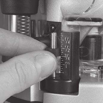
6 GB ALWAYS switch off and wait until the bit has come to a complete standstill before removing the machine from the workpivvece Disconnect from the power supply before carrying out any adjustment, servicing or maintenance WARNING: Dust generated by using power tools can be toxic. Some materials may be chemically treated or coated and be a toxic hazard. Some natural and composite materials may contain toxic chemicals. Some older paints may contain lead and other chemicals. Avoid prolonged exposure to dust generated from operating a router. DO NOT allow dust to get onto skin or eyes and do not allow the dust to enter your mouth to prevent absorption of harmful chemicals. Where possible, work in a well-ventilated area. Use a suitable dust mask and dust extraction system where possible. Where there is a higher frequency of exposure, it is more critical that all safety precautions are followed and a higher level of personal protection is used. Product Familiarisation 1. Turret Stops 2. Chuck 3. Shaft Lock Pin 4. Depth Stop 5. Depth Stop Lock Knob 6. Plunge Selection Button 7. Winder Handle 8. Winder Handle Clutch Ring 9. Brush Access Covers 10. Micro Winder 11. Motor 12. Power Switch 13. Retracting Power Switch Cover 14. Plunge Spring Access Cap 15. Speed Controller 16. Plunge Lock Lever 17. Safety Guards 18. Dust Extraction Port 19. Circle Cutting Pivot Mount 20. Baseplate Mounting Knobs 21. Fence 22. Collet (see specification table for sizes) 23. Spanner 24. Extended Baseplate 25. Table Height Winder 26. Table Height Winder Connection Point Intended Use Hand-held, mains-powered plunge router used for cutting profiles, grooves, edges and elongated holes in natural and composite wood, and also stationary installation in the Triton Precision Router Table, the Triton Workcentre, and other suitable table systems. Unpacking Your Tool Carefully unpack and inspect your new plunge router. Familiarise yourself with all its features and functions Ensure that all parts of the tool are present and in good condition If any parts are missing or damaged, have such parts replaced before attempting to use this tool Before Use WARNING: Ensure the tool is disconnected from the power supply before attaching or changing any accessories, or making any adjustments. Collet and cutter installation Note: Wear protective gloves when inserting and removing router bits due to the sharp edges of the cutters. 1. Place the router upside down on a secure flat surface, with the motor completely stationary and the power cable removed from the mains 2. Plunge the router to its maximum depth by pressing the Winder Handle Clutch Ring (8) inwards, and turning the Winder Handle (7) clockwise until the Collet (22) is protruding the base (Image C) Note: Ensure the Depth Stop (4) is fully retracted (see Depth stop and turret ). The Collet (22) should be protruding through the base, allowing easy spanner access. 3. Using the Spanner (23) provided, loosen the Collet by turning it anti-clockwise until removal (Image D) 4. Select the desired Collet, and install into the Chuck (2) by screwing the Collet in clockwise 5. Insert the router cutter into the Collet ensuring that at least 20mm or half of the shaft (whichever is greater) is inserted into the Collet, then use the Spanner (23) to turn the Collet slightly, allowing the collet lock to engage. Once engaged, turn the spanner clockwise to tighten the cutter 6. Return the router to a normal operating depth. This will disengage the collet lock and release the retracting switch shutter, enabling access to the Power Switch (12) Dust extraction port Note: The Triton Router is equipped with a Dust Extraction Port (18) for chip extraction above the cut. The Dust Extraction Port accepts 38mm (1½ ) outer-diameter hose. It is also compatible with the Triton Dust Collector (DCA300) and the Triton Dust Port Adaptor (TDPADIN) which allows for third-party hoses to be attached. The dust extraction hose screws into position via a left-hand thread (anti-clockwise) Extended baseplate and fence installation Note: When using the router with the baseplate fitted, place one hand on the long end of the base, holding it down onto your work, and grip the router handle, furthest away, with your other hand. 1. Locate the two Baseplate Mounting Knobs (20) and loosen them entirely. This permits the mounting studs to engage the router securing holes on the Extended Baseplate (24) 2. Turn both the plunge router and the Extended Baseplate upside down 3. Press the Baseplate Mounting Knobs on the plunge router inwards, to expose the mounting studs 4. Align the mounting studs with the router securing holes on the Extended Baseplate (24), and slide into the keyhole slots (image E). Note: The extended baseplate orientation is dependent on where the support is required. For edge work, locate the Power Switch (12) on the short overhang side of the base 5. Tighten the Baseplate Mounting Knobs on the plunge router firmly to secure the plunge router to the Extended Baseplate 6. To fit the Fence (21) loosen the fence knobs, and slide the fence along the tracks on the Extended Baseplate (Image F). Lock at the required setting by tightening both fence knobs Note: When routing trenches at distance from an edge, fit the fence to the long end of the baseplate. Note: When performing edge work with a non-bearing guided cutter, fit the fence to the short end of the baseplate (Image G) Note: If using a very large diameter cutter it may be necessary to fix wooden blocks to the fence faces via the screw holes, to ensure the cutter does not contact the fence. Operation WARNING: ALWAYS wear eye protection, adequate respiratory and hearing protection, as well as suitable gloves, when working with this tool. Switching on and off Note: When the router is connected to the power source, the Power Switch (12) will illuminate in both On and Off positions. Note: The Retracting Power Switch Cover (13) prevents accidental starting of the router. It must be retracted before the router can be switched on (Image A). The cover will remain open until the router is switched off. 1. Ensure that the plunge router is at the maximum extension of its travel, and that the cutter will not conflict with any foreign objects when it is powered on 2. Connect the power cord to the mains, and slide the Retracting Power Switch Cover back to reveal the Power Switch 3. Press the Power Switch in the I position to turn the plunge router ON (Image B). Whilst the Power Switch is in this position, the Retracting Power Switch Cover will be prevented from re-covering the Power Switch 4. To turn OFF, press the Power Switch in the O position. The Retracting Power Switch Cover will slide back to its original position Variable speed control Note: Router speed settings are not critical. Generally the highest speed which does not result in burn marks on the workpiece should be used. Where stated, always follow the cutter manufacturers maximum speed limitations. Operating at reduced speed increases the risk of damage to the router as a result of overload. Use very slow feed rates and/or multiple shallow cuts. The Speed Controller (15) is marked 1 to 5, corresponding approximately with the speeds and cutter diameters below. Turn the dial to select the required speed (image H) 6
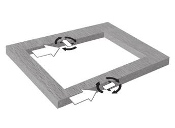
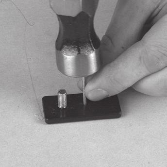
7 Setting RPM Cutter Diameter 5 21,000 Up to 1" 4 18,000 1" - 2" 3 14,500 2" - 2½" 2 11,000 Over 2½" 1 8,000 Use only if burning Cutting depth adjustment Note: To lock the router at a particular depth of cut, plunge the router head down and rotate the Plunge Lock Lever (16) to its lower position. This will hold the router head in this position There are three methods of cut depth adjustment, depending on the accuracy and control required: Free plunge 1. Free plunge depth adjustments can be made with the Plunge Selection Button (6) engaged. Press the Plunge Selection Button deep inside the handle until it engages inward (image I) 2. Release the Plunge Lock Lever (16) and push the body of the router until the required depth is reached. Re-lock the Plunge Lock Lever Note: The position of the Plunge Lock Lever can be altered by removing its retaining screw and repositioning the lever on the bolt. Re-tighten firmly. Winder handle adjustment 1. Plunge depth adjustments can be made by turning the Winder Handle (7) 2. Disengage the Plunge Selection Button (6) and ensure that the button is flush with the Winder Handle (Image J) 3. To release the handle, pull the Winder Handle Clutch Ring (8) inwards 4. Release the Plunge Lock Lever (16) and twist the Winder Handle until the desired depth of cut is reached. Release the Winder Handle Clutch Ring, and lock the Plunge Lock Lever Micro Winder Note: For use in Winder Handle (7) plunge mode only. 1. Disengage the Plunge Selection Button (6), and ensure that the Plunge Lock Lever (16) is unlocked Note: If the Micro Winder (10) is turned with the Plunge Lock Lever engaged, the Micro Winder will start clicking and the cut depth will remain unchanged. 2. Turn the Micro Winder clockwise to increase cut depth and anti-clockwise to reduce cut depth. Adjust the cut depth until the desired height is reached (Image K) Note:When the end of the depth adjustment range is reached, the Micro Winder will offer greater resistance and will begin to click. 3. Engage the Plunge Lock Lever, particularly for heavy cuts Depth stop and turret 1. The Depth Stop (4) and Turret Stops (1) are used to accurately pre-set up to three different cut depths 2. Loosen the Depth Stop Lock Knob (5) and retract the Depth Stop (4) fully, then retighten (Image L) 3. Set the turret posts to the required plunge depths using the scales on the stationary turret post (Image M) Note: To change turret posts, rotate the entire turret assembly to align with the Depth Stop (Image N) 4. With the desired cutter installed into the Collet (22), adjust the plunge depth until the tip of the cutter touches the workpiece 5. Rotate the turret until the fixed turret post is in line with the Depth Stop. Release the stop, allowing it to spring onto the post, then retighten the Depth Stop Lock Knob. The plunge depth is now set at zero (Image O) 6. Rotate the Turret Stops until the turret post with the desired plunge depth is aligned with the Depth Stop Making a cut Note: NEVER operate the router freehand without some form of guide. Guidance can be provided by a bearing guided router bit cutter, the supplied guides, or a straight edge (Image P) 1. ALWAYS hold the router using both hands, on the handles provided. Ensure that the workpiece will not move. Use clamps wherever possible 2. Allow the motor to reach its full operating speed 3. Lower the router bit cutter into the workpiece whilst moving the router slowly, keeping the base plate held flat against the workpiece 4. If edge cutting, the cutting of the workpiece should be on the left side relative to the cutting direction (Image Q). Keep the pressure constant and allow the cutter to work steadily through the material. Be aware that knots, and other variations, will slow the rate of progress Note: To avoid 'bit chatter', direct the cut anti-clockwise for external cuts, and clockwise for internal cuts. Note: Moving the router too fast can result in a poor quality finish, and overloading of the motor. Moving the router too slowly can result in overheating the workpiece. Note: Normal operation of a router is to plunge the head after the router has been switched on. Note:Do not operate the router upside down unless securely mounted in a well-guarded router table (eg. Triton brand). Making multiple pass cuts 1. The Turret Stops (1) allow the maximum depth of cut to be achieved in an operatordetermined number of steps. Each step of the turret can be preset by adjusting the thumbwheel on the turret post 2. Rotate the Turret Stops so that the Depth Stop will contact the highest pre-set turret post when the router is plunged. The first pass of the cut can now be made 3. Continue to make passes, rotating the Turret Stops and adjusting the turret post depth for each pass when necessary until the full depth of cut has been achieved Circle cutting 1. Fit the Extended Baseplate (24), without the Fence (21) attachment, to the router 2. Remove the Circle Cutting Pivot Mount (19) from the Extended Baseplate and fix it to the centre of the workpiece, using a small nail or screw, through one of the holes in the pivot mount (Image R). Leave the pivot mount bolt in position 3. Lower the router and base over the pivot mount and refit the washer and wing-nut (Image S) 4. With the power switched Off, rotate the router along the intended path to check the circle, and make any necessary adjustments 5. Cut the circle in several passes, lowering the cut depth by approximately 2mm (1 13") each pass (Image T). Do not attempt to cut deeply in one pass Through cuts: If cutting all the way through the material, fix a sacrificial board to the underneath of the workpiece. Cut the circle oversize, then when the cut is all the way through, reduce the diameter and work back to the required size, using light, full depth passes Table-mounted operation WARNING: When in use with the Triton Workcentre Router Table Module WX7RT001, the maximum cutter diameter is ". This is constrained by the Workcentre specification. Note: Fitting and operating this router on a router table should be carried out in accordance with the literature supplied with the router table. Note: Whilst this product was designed for efficient and convenient operation on most router tables, it is particularly suited for use with the Triton Router Table RTA300. Note: The plunge spring MUST be removed before this router is fitted into a router table: 1. Set the router at the top of its plunge range and engage the Plunge Lock Lever (16) 2. Loosen the small screw next to the Plunge Spring Access Cap (14) a few turns. 3. Holding the Plunge Spring Access Cap firmly so that the spring will not shoot upwards when released, twist the cap anti-clockwise to remove it (image U) 4. Remove the spring and store in a safe place. 5. Replace the Plunge Spring Access Cap and re-tighten the screw. Note: Be sure to re-fit the plunge spring before using the router freehand. The Table Height Winder (25) engages with the Table Height Winder Connection Point (26) for quick and easy above-the-table height adjustment when the router is table-mounted (image V) Accessories A wide range of suitable accessories for this tool are available from your Triton stockist, including a large selection of cutter/router bits. Spares including carbon brushes, guide bushes and collets are available from your Triton stockist or Maintenance WARNING: ALWAYS disconnect from the power supply before carrying out any inspection, maintenance or cleaning. General inspection Regularly check that all the fixing screws are tight Inspect the supply cord of the tool, prior to each use, for damage or wear. Repairs should be carried out by an authorised Triton service centre. This advice also applies to extension cords used with this tool Cleaning WARNING: ALWAYS wear protective equipment including eye protection and gloves when cleaning this tool. Keep your tool clean at all times. Dirt and dust will cause internal parts to wear quickly, and shorten the device s service life Clean the body of your machine with a soft brush, or dry cloth Never use caustic agents to clean plastic parts. If dry cleaning is not sufficient, a mild detergent on a damp cloth is recommended 7 GB
8 Water must never come into contact with the tool Ensure the tool is thoroughly dry before using it If available, use clean, dry, compressed air to blow through the ventilation holes (where applicable) Lubrication Slightly lubricate all moving parts at regular intervals with a suitable spray lubricant Brushes Over time the carbon brushes inside the motor may become worn Excessively worn brushes may cause loss of power, intermittent failure, or visible sparking To replace the brushes, remove the two Brush Access Covers (9). Remove the worn brushes and ensure the sockets are clean. Carefully replace with new brushes and then replace the Brush Access Covers After fitting run the router without load for 2-3 minutes to help the brushes bed in. The process of the brushes fully bedding in may take repeated uses. Motor sparking may continue until new carbon brushes have bedded in Alternatively, have the machine serviced at an authorised service centre Storage Store this tool carefully in a secure, dry place out of the reach of children Disposal Always adhere to national regulations when disposing of power tools that are no longer functional and are not viable for repair. Do not dispose of power tools, or other waste electrical and electronic equipment (WEEE), with household waste Contact your local waste disposal authority for information on the correct way to dispose of power tools Troubleshooting Problem Possible cause Solution No function when Power Switch (12) is operated No power Check power supply Defective On/Off Power Switch Replace the Power Switch at an authorised Triton service centre Inaccurate cutting profile Depth Stop (4) not correctly adjusted Ensure that the Depth Stop corresponds to the maximum amount of cut permitted by the Turret Stops (1) Incorrectly fitted or loose router bit/collet (22) Tighten router bit/collet and cutter assembly Router will not operate No supply of power Check that power is available at source Brushes worn or sticking Power Switch (12) is faulty Motor components faulty or short circuited Disconnect power, open Brush Access Covers (9) and ensure brushes are not damaged or heavily worn Have the tool serviced by an authorised Triton service centre Have the tool serviced by an authorised Triton service centre Router runs or cuts slowly Blunt or damaged cutter Re-sharpen or replace cutter Speed Controller (15) set low Motor is overloaded Increase variable speed setting Reduce pushing force on router GB Excessive vibration Incorrectly fitted or loose router bit Refit or tighten router bit Bent or damaged router bit Replace router bit Heavy sparking occurs inside motor housing Brushes not moving freely Disconnect power, remove brushes, clean or replace Damaged or worn motor Have the tool serviced by an authorised Triton service centre Micro Winder (10) clicks or not adjusting Plunge Lock Lever (16) engaged Release Plunge Lock Lever (16) Reached end of adjustment range Reset Micro Winder (10) and set depth with the Depth Stop (4) Makes an unusual sound Mechanical obstruction Have the tool serviced by an authorised Triton service centre Damage to internal windings Have the tool serviced by an authorised Triton service centre 8
9 Guarantee To register your guarantee visit our web site at and enter your details. Your details will be included on our mailing list (unless indicated otherwise) for information on future releases. Details provided will not be made available to any third party. Purchase Record Date of Purchase: / / Model: MOF001 Retain your receipt as proof of purchase art pr Triton Precision Power Tools guarantees to the purchaser of this product that if any part proves to be defective due to faulty materials or workmanship within 3 YEARS from the date of original purchase, Triton will repair, or at its discretion replace, the faulty part free of charge. This guarantee does not apply to commercial use nor does it extend to normal wear and tear or damage as a result of accident, abuse or misuse. * Register online within 30 days. Terms & conditions apply. This does not affect your statutory rights oves to be defecti GB 9
10 Traduction des instructions originales Introduction Nous vous remercions d avoir choisi cet équipement Triton. Ces instructions contiennent les informations nécessaires pour vous en garantir un fonctionnement efficace et en toute sécurité. Veuillez lire attentivement ce manuel pour vous assurer de tirer pleinement avantage des caractéristiques uniques de votre nouvel équipement. Gardez ce manuel à portée de main et assurez-vous que tous les utilisateurs l aient lu et bien compris avant toute utilisation. Conservez-le pour toute référence ultérieure. Symboles La plaque signalétique figurant sur votre outil peut présenter des symboles. Ces symboles constituent des informations importantes relatives au produit ou des instructions concernant son utilisation. Port de protection auditive Port de lunettes de sécurité Port de masque respiratoire Port de casque Abréviations pour les termes techniques V Volts ~ Courant alternatif A Ampère n0 Vitesse à vide Hz Hertz W, kw Watt, kilowatt /min or min -1 (tours) par minute Caractéristiques techniques Port de gants Lire le manuel d instructions Numéro de produit : Tension : Puissance : Régime à vide : MOF V~, 60 Hz, 13 A W / 2 ¼ ch. en crête de à tr/min NE PAS utiliser sous la pluie ou dans un environnement humide! Pince de serrage : 1/2"et 1/4" Diamètre max de coupe : 2 3/16" / 2 ", 55 mm / 50 mm (lorsqu il est utilisé avec WX7RT001) ATTENTION : les pièces mobiles peuvent engendrer des écrasements et des coupures. Réglage de la plongée 1) Libre 2) Poignée remontoir 3) Réglage micrométrique Attention! Attention à l effet de rebond! Double isolation pour une protection supplémentaire Course de plongée : 59 mm / " Classe d isolation : Poids net : 5,97 kg / 13,16 lbs Du fait de l évolution constante de nos produits, les caractéristiques des produits Triton peuvent changer sans notification préalable Conforme à la règlementation et aux normes européennes de sécurité pertinentes Protection de l environnement Les produits électriques usagés ne doivent pas être jetés avec les ordures ménagères. Veuillez les recycler dans les centres prévus à cet effet. Pour de plus amples informations, veuillez contacter votre municipalité ou point de vente. FR ATTENTION : Portez toujours des protections sonores lorsque le niveau d intensité est supérieur à 85 db(a) et limitez le temps d exposition si nécessaire. Si l intensité sonore devient inconfortable, même avec les protections, arrêtez immédiatement d utiliser l appareil, vérifiez que les protections sont bien en places et adaptés avec le niveau sonore produit par l appareil. ATTENTION : L exposition de l utilisateur aux vibrations peut engendrer une perte du toucher, des engourdissements, des picotements et ainsi réduire la capacité de préhension. De longues expositions peuvent également provoquer ces symptômes de façon chronique. Si nécessaire, limitez le temps d exposition aux vibrations et portez des gants anti-vibrations. N utilisez pas cet appareil lorsque la température de vos mains est en dessous des températures normales, car l effet vibratoire en est accentué. Référez-vous au cas de figures des caractéristiques relatives aux vibrations pour calculer le temps et fréquence d utilisation de l appareil. Un mauvais entretien, un assemblage mal réalisé ou une utilisation ne correspondant pas à l usage conforme indiqué peut avoir pour conséquence une émission sonore et vibratoire accrue. 10
11 Consignes de sécurité générales et électriques spécifiques aux USA En cas de dysfonctionnement ou de panne, la mise à la terre offre une résistance moindre au courant électrique pour réduire les risques d électrocution. Cet appareil est équipé d un cordon électrique comportant un dispositif de mise à la terre et d une prise disposant d une mise à la de terre. La fiche doit être branchée dans une prise qui a été installée et mise à la terre de façon appropriée, en accord avec les normes et lois locales. Ne modifiez pas la fiche équipant cet appareil si elle n est pas compatible avec la prise, faites installer une prise appropriée par un électricien qualifié. Un mauvais raccordement de l'appareil à la prise de terre peut entraîner un choc électrique. Le fil vert, avec ou sans rayures jaunes, est le dispositif de mise à la terre de cet appareil Si une réparation ou un remplacement du cordon électrique s'avère nécessaire, ne branchez pas le dispositif de mise à la terre de l'équipement sur la phase. Vérifiez auprès d'un électricien ou d'un technicien compétent si les instructions de mise à la terre de l'appareil ne sont pas claires, ou si vous avez des doutes sur la mise à la terre de ce produit. N'utilisez que des rallonges à fil triple ayant 3 broches dont une mise à la terre et des prises trois broches acceptant la fiche d'alimentation de ce produit. Réparez ou remplacez immédiatement un cordon endommagé 1. MAINTENEZ LES PROTECTEURS EN PLACE et en état de marche 2. ENLEVEZ LES CLÉS ET OUTILS DE RÉGLAGE. Prenez l'habitude de vérifier que les clés et outils de réglages ont été enlevés de l'outil avant de le mettre en marche 3. MAINTENEZ LA ZONE DE TRAVAIL PROPRE. Les zones et les établis encombrés peuvent être source d accidents. 4. N UTILISEZ PAS DANS DES ENVIRONNEMENTS DANGEREUX. N utilisez pas d outils électriques dans les lieux humides ou mouillés, ne les exposez pas à la pluie. Gardez la zone bien éclairée. 5. MAINTENEZ LES ENFANTS À L ÉCART. Gardez les visiteurs à une distance de sécurité suffisante de la zone de travail. 6. ASSUREZ-VOUS QUE L ATELIER EST SÛR POUR LES ENFANTS, utilisez des cadenas, des interrupteurs généraux et enlevez les clés de démarrage. 7. NE FORCEZ PAS LES OUTILS. Les outils fonctionnent mieux et de manière plus sûre lorsqu ils travaillent au rythme pour lequel ils ont été conçus. 8. UTILISEZ LE BON OUTIL. Ne forcez pas un outil ou un accessoire à effectuer une tâche pour lequel il n a pas été conçu. 9. UTILISEZ UNE RALLONGE ADAPTÉE. Vérifiez que les rallonges électriques sont en bon état. Lors de l utilisation d une rallonge, assurez-vous qu elle est adaptée au transport du courant demandé par l appareil. Un câble trop petit entraînera une baisse de tension et conduira à une perte de puissance et une surchauffe. Le tableau ci-dessous indique la taille adaptée en fonction de la longueur du câble et de son ampérage. En cas de doute, utilisez un cordon d'un calibre plus élevé. Plus la valeur du calibre est petite, plus le câble est résistant. Longueur du total du câble en pieds (ft) 25 ft 18 AWG 50 ft 16 AWG 100 ft 14 AWG 150 ft 12 AWG Calibre du câble 10. PORTEZ DES VÊTEMENTS ADAPTÉS. Ne portez pas de vêtements s amples, gants, cravates, bagues, bracelets et autres bijoux qui pourraient être happés par les parties mobiles. Le port de chaussures antidérapantes est recommandé. Couvrez et attachez les cheveux longs. 11. PORTEZ TOUJOURS DES LUNETTES DE PROTECTION. Portez également un masque antipoussière si la coupe entraîne la production de poussière. Les lunettes de vue ne disposent que de verre résistant aux impacts et ne sont PAS des lunettes de sécurité. 12. MAINTENEZ LES PIÈCES À TRAVAILLER EN PLACE. Utilisez des pinces ou un étau lorsque cela est possible. Cela rend le travail plus sûr et permet d utiliser les deux mains pour contrôler l outil. 13. NE VOUS PENCHEZ PAS TROP. Restez en équilibre en permanence. 14. ENTRETENEZ VOS OUTILS CONVENABLEMENT. Aiguisez et nettoyez vos outils pour obtenir les meilleurs résultats en toute sécurité. Suivez les instructions pour la lubrification et le changement des accessoires. 15. DÉBRANCHEZ LES OUTILS avant d effectuer l entretien, et lors du changement d accessoires tels que les lames, les embouts, etc. 16. RÉDUISEZ LE RISQUE DE DÉMARRAGE IMPRÉVU. Assurez-vous que l interrupteur est en position «arrêt» avant de brancher l appareil. 17. UTILISEZ LES ACCESSOIRES RECOMMANDÉS. Référez-vous au manuel d utilisation pour connaître les accessoires recommandés. L utilisation d accessoires non recommandés peut entraîner un risque de blessure. 18. NE VOUS APPUYEZ PAS SUR L OUTIL. Tout contact avec l outil peut causer des blessures graves. 19. VÉRIFIEZ L ÉTAT DE L OUTIL. Avant d'utiliser l'outil de nouveau, examinez soigneusement les pièces et dispositifs de protection qui semblent endommagés afin de déterminer s'ils fonctionnent correctement et s'ils remplissent les fonctions prévues. Vérifiez l'alignement des pièces mobiles, la fixation des pièces mobiles, le bris de pièces ou de montures, et toute autre condition qui pourrait affecter le bon fonctionnement. Faire réparer ou remplacer tout capot de protection ou autres pièces endommagées comme il se doit. 20. SENS DE D UTILISATION. Faites avancer la pièce dans le sens contraire à la direction de la lame. 21. NE LAISSEZ JAMAIS UN OUTIL EN FONCTIONNEMENT SANS SURVEILLANCE. Éteignez l appareil. Ne laissez pas l outil sans surveillance tant qu il n est pas complètement arrêté. AVERTISSEMENT Certaines poussières générées par le ponçage, sciage, le perçage et d autres activités de constructions électriques contiennent des substances chimiques reconnues dans l'état de la Californie comme étant une cause de cancer, de malformations congénitales et d autres problèmes reproductifs. Des exemples de ces substances chimiques sont : Le plomb, provenant des peintures à base de plomb La silice cristalline, provenant des briques, du ciment et d autre matériaux de construction L arsenic et le chrome, provenant des caoutchoucs traités chimiquement Les risques résultant de ces expositions varient en fonction de la fréquence à laquelle vous effectuez ce type de travaux. Pour réduire l exposition à ces substances chimiques : travaillez dans une zone ventilée et portez un équipement adapté, comme un masque à poussière conçu spécialement pour filtrer les particules microscopiques. Consignes de sécurité relatives à l utilisation de défonceuses AVERTISSEMENT Tenez l outil électrique par ses surfaces de préhension isolées, au cas où la fraise rentre en contact avec des câbles et fils cachés. Lorsqu ils sont en contact avec un câble sous tension, ils peuvent exposer les pièces métalliques de l outil à une tension et peuvent entraîner un choc électrique. Immobilisez la pièce de travail à l aide d un étau ou d une pince de serrage sur une surface stable. Maintenir la pièce de travail à la main ou contre le corps peut engendrer une perte de contrôle. S il est nécessaire de remplacer le cordon d alimentation, cela doit être fait par le fabricant ou un de ses agents agréés pour éviter tout danger. Il est fortement recommandé d alimenter l outil à travers un disjoncteur différentiel (RCD) dont le courant résiduel nominale est de 30 ma ou moins. a) Portez des équipements de sécurité tels que des lunettes ou une visière, des protections auditives, un masque respiratoire et des vêtements de protection tel que des gants de sécurité. b) Les chiffons, cordes, ficelles etc. ne doivent jamais être laissés dans l espace de travail. c) Assurez-vous que la tension de la source principale d alimentation soit la même que celle indiquée sur la plaque signalétique de l appareil. d) Assurez-vous que toutes les rallonges électriques utilisées avec l appareil soient électriquement sûre, et qu elles possèdent l ampérage indiqué pour l appareil. e) Déroulez complètement les rallonges de l enrouleur pour éviter toute surchauffe. f) Utilisez un détecteur approprié pour déterminer si des câbles ou conduites se trouvent sous la surface de la zone de travail. Contactez les sociétés des services publiques appropriées si nécessaire. Un contact avec des câbles électriques peut engendrer des chocs électriques et des incendies. Endommager une conduite de gaz peut engendrer une explosion. Un contact avec une conduite d eau peut provoquer des dommages matériels importants. g) Assurez-vous d avoir enlevé les corps étrangers tels que les clous et les vis de la pièce de travail avant de commencer à travailler. h) Manipulez les fraises avec précaution car elles peuvent être extrêmement tranchantes. i) Avant utilisation, vérifiez avec précaution que l embout ne soit pas endommagé ou fissuré. Remplacez immédiatement les embouts endommagés ou fissurés. j) Assurez-vous que les fraises/embouts sont aiguisés et entretenus correctement. Si les tranchants son émoussés, cela peut engendrer des pertes de contrôle, le calage de l appareil, une augmentation de la chaleur et des blessures. k) Utilisez TOUJOURS les deux mains et maintenez fermement la défonceuse avant de commencer tout travail. l) Gardez les poignées et les surfaces de préhension sèches, propres et sans huile ou graisse pour assurer une prise en main sûre de l appareil pendant son utilisation. m) Avant d utiliser l appareil pour faire une coupe, mettez-le en marche et laissez-le fonctionner librement pendant quelques instants. Des vibrations peuvent indiquer un embout mal installé. n) Notez le sens de rotation de la fraise et celui du déplacement de l outil. o) Gardez vos mains éloignées de la zone de défonçage et de la fraise. Maintenez la poignée auxiliaire ou les surfaces de préhension isolantes avec votre deuxième main. p) Ne démarrez JAMAIS la défonceuse lorsque la fraise est en contact avec la pièce de travail. q) Assurez-vous toujours que le ressort de plongée est installé pendant l utilisation à la main de la défonceuse. r) Assurez-vous que la fraise est complètement arrêtée avant de plonger vers la position de verrouillage de la pince de serrage. FR 11
12 FR s) La vitesse maximale de la fraise/l embout doit être au moins aussi élevée que celle de l appareil. t) Des parties de la fraise peuvent devenir extrêmement chaudes pendant l utilisation. Ne manipulez pas immédiatement après l utilisation pour éviter le risque de brûlure. u) Ne laissez aucune pièce venir en contact avec des matériaux combustibles v) La taille de la tige de la fraise/l embout doit être exactement de la même taille de la pince de serrage installée sur la défonceuse. Une fraise/un embout incorrectement installé(e) aura un mouvement de rotation irrégulier et augmentera les vibrations, cela peut engendrer une perte de contrôle. w) N essayez JAMAIS d appuyer sur le bouton de bocage de l arbre ou de mettre l appareil en mode de changement d embout lorsque l appareil est en marche. x) Gardez une pression constante lors d une coupe dans la pièce de travail, en laissant la fraise décider de la vitesse de coupe. Ne forcez pas sur l appareil, et ne surchargez pas le moteur. y) Assurez-vous que les étiquettes et les avertissements de sécurité sur l appareil restent lisibles et remplacez-les s ils sont endommagés ou abîmés. z) Lorsque vous utilisez la défonceuse, restez sur vos garde ; la fraise pourrait caler, entrainant une perte de contrôle. Assurez-vous toujours de bien maintenir la défonceuse. Dans de telles circonstances, soyez prêt à relâcher l interrupteur de marche/arrêt immédiatement. Après avoir éteint la défonceuse, vérifiez que la fraise a un mouvement de rotation régulier (non vacillant) et qu il n y a pas de vibrations supplémentaires dues à une fraise mal installée. Faire fonctionner la défonceuse avec une fraise mal installée peut engendrer une perte de contrôle et des blessures graves. Une extrême précaution est requise lorsque vous utilisez des fraises d un diamètre supérieur à 2" (50 mm). Faites descendre la fraise lentement et/ou faites de multiples fraisages peu profonds pour éviter la surcharge du moteur. Éteignez TOUJOURS l appareil et attendez que l embout soit complètement arrêté avant de le retirer de la pièce de travail. Débranchez l appareil de sa source d alimentation avant d effectuer un réglage, l entretien ou la révision. ATTENTION : Les poussières générées par des outils électroportatifs peuvent être toxiques. Certains matériaux peuvent être traités chimiquement ou avoir un revêtement, et présenter un risque toxique. Certains matériaux naturels ou composites peuvent contenir des produits chimiques toxiques. Certaines peintures anciennes peuvent contenir du plomb et d autres produits chimiques. Évitez les longues expositions à la poussière créée par l utilisation de la défonceuse. NE laissez PAS la poussière se poser sur la peau ou les yeux, et ne laissez pas la poussière rentrer dans la bouche pour éviter l absorption de produits chimiques nocifs. Si possible, travaillez dans un endroit bien ventilé. Utilisez un masque respiratoire et un système d extraction de la poussière adéquats. Là où il y a une plus grande fréquence d exposition, il est encore plus important que toutes les précautions de sécurité soient respectées et que des protections personnelles d un niveau supérieur soient utilisées. Descriptif du produit 1. Butoir de tourelle 2. Mandrin 3. Goupille de verrouillage de l arbre 4. Butée de profondeur 5. Bouton de verrouillage de la butée de profondeur 6. Sélecteur du mode de plongée 7. Poignée du remontoir 8. Bague d embrayage de la poignée remontoir 9. Cache des balais de charbons 10. Réglage micrométrique 11. Moteur 12. Interrupteur 13. Cache rétractable de sécurité de l interrupteur 14. Cache d accès au ressort de plongée 15. Réglage de la vitesse 16. Manette de verrouillage de la plongée 17. Pare-éclats 18. Tubulure d extraction de la sciure 19. Monture-pivot/compas 20. Boutons de montage de la plaque de guidage 21. Guide parallèle 22. Pince de serrage (pour les tailles, voir caractéristiques techniques) 23. Clé 24. Plaque de guidage 25. Poignée remontoir pour le réglage de la hauteur de la table 26. Point d attache de la poignée remontoir de la table Usage conforme Défonceuse à main s utilisant avec des fraises de ¼" et 8 mm (en fonction de la pince de serrage installée). S utilise pour couper des profils, des rainures, des bords et des trous oblongs dans les bois composites et naturels. Peut aussi être utilisée de manière fixe si elle est installée sur une table à défonceuse compatible. Déballer votre produit Déballez le produit avec soin. Veillez à retirer tous les matériaux d emballage et familiarisez-vous avec toutes les caractéristiques du produit. Assurez-vous qu aucune pièce n est manquante ni endommagée. S il s avérait qu une pièce est endommagée ou manquante, faites-la réparer ou remplacer avant d utiliser l appareil. Avant utilisation ATTENTION : Assurez-vous que l outil est débranché avant d installer ou de changer un accessoire ou d effectuer des réglages. Installation de la pince de serrage et de la fraise Remarque : Portez des gants de protection lorsque vous installez ou enlevez les fraises, les tranchants sont très affûtés. 1. Placez la défonceuse dessus dessous sur une surface plane et sûre, le moteur doit être compétemment arrêté et le câble d alimentation débranché. 2. Faites descendre la défonceuse à son maximum en appuyant sur la bague d embrayage de la poignée remontoir (8) vers l intérieur, tournez la poignée du remontoir (7) dans le sens horaire jusqu à ce que la pince de serrage (22) dépasse à la base (image C). Remarque : Assurez-vous que la butée de profondeur (4) est complètement rétractée (voir «Tourelle et butée de profondeur»). La pince de serrage devrait dépasser de la base, permettant un passage facile de la clé. 3. En utilisant la clé (23) fournie, desserrez la pince de serrage en la tournant dans le sens antihoraire jusqu à l enlever (image D) 4. Installez la pince de serrage désirée dans le mandarin (2) en vissant la pince de serrage dans le sens horaire. 5. Placez la fraise dans la pince de serrage en vous assurant qu au moins 20 mm ou la moitié de la tige (le plus grand des deux) est (sont) inséré(s) dans la pince, puis utilisez la clé (23) pour tourner légèrement la pince de serrage tout en laissant le verrouillage de la pince de serrage s enclencher. Lorsqu il est enclenché, tournez la clé dans le sens horaire pour serrer la fraise. 6. Réglez de nouveau la défonceuse à une profondeur normale. Cela dégagera le verrouillage de la pince de serrage et relâchera le cache de l interrupteur (12), le rendant de nouveau accessible. Tubulure d extraction de la sciure Remarque : Cette défonceuse Triton est pourvue d une tubulure d extraction de la sciure (18) permettant l élimination de la sciure au-dessus de la coupe. Elle permet le raccord de tuyau d un diamètre extérieur de 38 mm (1/2"), tel que celui fourni avec le collecteur de sciure Triton (DCA300) et l adaptateur pour tubulure d extraction de la poussière (TDPADIN), afin de pouvoir adapter un système d aspiration. Le tuyau s adapte en le visant sur un filetage à gauche (dans le sens antihoraire). Installation du guide et de la plaque de guidage Remarque : Lors de l utilisation de la défonceuse avec la plaque de guidage, placez une main sur le côté long de la plaque, maintenez-la sur la pièce à usiner, et tenez la poignée de la défonceuse avec l autre main. 1. Desserrez les boutons de montage de la plaque de guidage (20). Cela permet aux ergots de montage de se mettre en place dans les trous de la plaque de guidage (24). 2. Mettez la défonceuse et la plaque de guidage dessus dessous. 3. Poussez les boutons de montage de la plaque de guidage sur l intérieur de la défonceuse afin de montrer les ergots de montage. 4. Alignez les ergots de montage avec les trous de montage de la défonceuse situés sur la plaque de guidage, faites les glissés dans les fentes (image E). Remarque : Le sens de la plaque de guidage dépend de l endroit où le support est nécessaire. Pour travailler sur un bord, placez l interrupteur (12) du côté de la plaque le plus court. 5. Serrez fermement les boutons de montage de la plaque de guidage sur la défonceuse afin de maintenir la défonceuse sur la plaque de guidage. (image F) 6. Verrouillez sur le réglage souhaité en vissant les deux boutons du guide Remarque : Lorsque vous effectuez un rainurage, installez le guide sur le côté long de la plaque. Remarque : Lorsque vous effectuez un travail sur le bord avec une fraise sans roulement, installez le guide sur le côté court de la plaque de guidage (image G). Remarque : Si vous utilisez une fraise de large diamètre, il peut être nécessaire d installer des pièces de bois le long du guide en utilisant les trous de vissage pour éviter que la fraise ne rentre en contact avec le guide. 12
SAFETY AND OPERATING MANUAL
 SAFETY AND OPERATING MANUAL General Safety Rules WARNING! Read all instructions. Failure to follow all instructions listed below may result in electric shock, fire and/ or serious injury. The term power
Product instruction manual Ream Cutting Systems RE3943, RE3946, RE3947, RE3971, RE3952E
 Product instruction manual Ream Cutting Systems RE3943, RE3946, RE3947, RE3971, RE3952E The Trimfast Ream Cutters are reliable, high performance cutters that will give you the results you need quickly
1. Configurez votre Stick Up Cam Wired dans l application Ring.
 Stick Up Cam Wired 1. Configurez votre Stick Up Cam Wired dans l application Ring. Téléchargez l application Ring. L application vous guide dans la configuration et l utilisation de votre Stick Up Cam
Meat Slicer INSTRUCTION MANUAL CAUTION! ONE YEAR LIMITED WARRANTY
 ONE YEAR LIMITED WARRANTY INSTRUCTION MANUAL The original registered owner of this product should contact SKYFOOD EQUIPMENT LLC at 305-868-16 for any warranty problems or service. SKYFOOD EQUIPMENT LLC
Installation and User s Manual 12 x 10 MOTORIZED AWNING
 12 x 10 MOTORIZED AWNING Installation and User s Manual 12 x 10 MOTORIZED AWNING 088-1763-0 Stop Please read and understand this manual before any assembly or use of this product. Before beginning assembly
DIAMOND TECH INTERNATIONAL Innovations For Creativity DIAMOND LASER BAND SAW OPERATIONS MANUAL
 SPEEDSTER-XL INSTRUCTION MANUAL DIAMOND TECH INTERNATIONAL Innovations For Creativity SPEEDSTER-XL DIAMOND LASER BAND SAW OPERATIONS MANUAL SPEEDSTER-XL INSTRUCTION MANUAL - PAGE 1 Before You Begin Read
Est A TRADITION OF EXCELLENCE INSTRUCTION BOOK.
 Est. 1887 A TRADITION OF EXCELLENCE INSTRUCTION BOOK www.wolseleygrooming.co.uk Stockshop (L.E.) Ltd., Lodge Trading Estate, Broadclyst, Exeter EX5 3BS Email: service@stockshop.co.uk Tel: 01392 460077
MAX Series 9514 OPERATOR S MANUAL
 MAX Series 9514 OPERATOR S MANUAL Persons under age 18 are not permitted to operate or have accessibility to operate this equipment per U.S. Dept. Of Labor Employment Standards Administration Fact Sheet
I We reserve the right to modify or attar Instructions. No modification or
 INSTALLATION INSTRUCTION VLFS3265 Floor Stand TV Mobile Cart For TV panels: 32"-65" Maximum load capacity: 100 lbs/ 45.5 kg AV shelf max load: 10 lbs/ 4.5 kg Video tray max load: 10 lbs/ 4.5 kg VESA: 100x100-600x400mm
Urea/Adblue Hose Reel
 www.scintex.com.au sales@scintex.com.au Model: SHR3408 Urea/Adblue Hose Reel Product Manual Specifications Spring driven drum: for automatic rewind. Locking ratchet: to maintain the desired length of hose
Thomas Scientific Swedesboro, NJ U.S.A.
 Thomas Scientific Swedesboro, NJ 08085-0099 U.S.A. Wiley Laboratory Mill, Model 4 3375-E10 (115 V, 50/60 HZ) USE AND CARE OF CATALOG NUMBER: 3375-E10 Wiley Laboratory Mill, Model 4 (115 V, 50/60 HZ) UNPACKING
AFC-50 Automatic French Fry Cutter Instruction Manual
 AFC-50 Automatic French Fry Cutter Instruction Manual Fry Factory Inc. 67 Watts Ave, Charlottetown, PEI, C1E 2B7, Canada Phone: 902-368-2900 Fax: 902-368-8645 Email: info@fryfactoryinc.com Website: www.fryfactoryinc.com
, & Series Nested Hardware
 RECORD THIS INFORMATION FOR FUTURE REFERENCE BEFORE INSTALLING THE UNIT: Model Number Serial Number Date Purchased Place of Purchase USA SERVICE OFFICE Dometic Corp. 509 So. Poplar St. LaGrange, IN 46761
MK3000. Operating and Calibration Instructions
 MK3000 Operating and Calibration Instructions CONTENT 1. INTRODUCTION 3 1.1. GENERAL INFORMATION. 3 1.2. WORKING PRINCIPLE. 3 1.3. SECTION THROUGH CUTTER.. 4 1.4. SPECIFICATIONS.. 5 2. INSTRUCTIONS FOR
Operator s Manual. Medium-Duty Electric Slicers ENGLISH. Item Model Description Drive Peak HP Voltage Amps Hz Plug
 Medium-Duty Electric Slicers 40950 40951 Item Model Description Drive Peak HP Voltage Amps Hz Plug 40950 SLM250/S 10 Knife Medium-Duty Slicer 1/3 2.5 Belt 120 60 5-15P 40951 SLM300P/S 12 Knife Medium-Duty
PATRIOT INSTRUCTION MANUAL SL300C 12 MEAT SLICER 1/2 HP
 INSTRUCTION MANUAL SL300C 12 MEAT SLICER 1/2 HP This manual contains important information regarding your Patriot unit. Please read this manual thoroughly prior to equipment set-up, operation and maintenance.
Bevel Buddy Instruction Manual
 Bevel Buddy Instruction Manual We at Precision Sharpening Devices Inc. believe there are two very important steps in maximizing the savings this equipment can provide your company. First, use this manual
Manual Awning. Assembly Instructions. Product No Toll-free:
 Manual Awning Product No. 088-30- Instructions Toll-free: -877-483-679 IMPORTANT: Please read this manual carefully before beginning assembly of this product. Keep this manual for future reference. 3 Table
RM4522TH Operator s Manual
 SAFETY INFORMATION CALIFORNIA PROPOSITION 65 WARNING: Battery posts, terminals and certain finished components contain lead, lead compounds and chemicals known to the State of California to cause cancer
1612P MODEL 1612P SLICER MODEL EXECUTIVE OFFICES 701 RIDGE AVENUE TROY, OHIO FORM (4-95)
") 1612P MODEL 1612P SLICER MODEL 1612P ML-104587 EXECUTIVE OFFICES 701 RIDGE AVENUE TROY, OHIO 45374-0001 FORM 19370 (4-95) Installation, Operation, and Care of MODEL 1612P SLICER SAVE THESE INSTRUCTIONS
1612P MODEL 1612P SLICER MODEL 1612P ML-104587 EXECUTIVE OFFICES 701 RIDGE AVENUE TROY, OHIO 45374-0001 FORM 19370 (4-95) Installation, Operation, and Care of MODEL 1612P SLICER SAVE THESE INSTRUCTIONS
USER MANUAL BMU WORKCAGE. CONFORM TO THE MACHINE DIRECTIVE 2006/42/EC and to EN1808 (1999)
") USER MANUAL BMU WORKCAGE CONFORM TO THE MACHINE DIRECTIVE 2006/42/EC and to EN1808 (1999) All persons operating this equipment must read and completely understand this manual. Any operation in violation
USER MANUAL BMU WORKCAGE CONFORM TO THE MACHINE DIRECTIVE 2006/42/EC and to EN1808 (1999) All persons operating this equipment must read and completely understand this manual. Any operation in violation
AUTO REWIND HOSE REEL WITH 50 FOOT HOSE. Model 46320
 AUTO REWIND HOSE REEL WITH 50 FOOT HOSE Model 46320 ASSEMBLY AND OPERATING INSTRUCTIONS 3491 Mission Oaks Blvd., Camarillo, CA 93011 Visit our Web site at http://www.harborfreight.com Copyright 2001 by
FORM (Apr. 2006)
") 2212 Slcier MODEL 2212 SLICER MODEL 2212 ML-136132 701 S. RIDGE AVENUE TROY, OHIO 45374-0001 937 332-3000 www.hobartcorp.com FORM 35215 (Apr. 2006) Installation, Operation, and Care of MODEL 2212 Slicer
2212 Slcier MODEL 2212 SLICER MODEL 2212 ML-136132 701 S. RIDGE AVENUE TROY, OHIO 45374-0001 937 332-3000 www.hobartcorp.com FORM 35215 (Apr. 2006) Installation, Operation, and Care of MODEL 2212 Slicer
INSTANT GARAGE MODEL NO: CIG81224 ASSEMBLY INSTRUCTIONS PART NO: ORIGINAL INSTRUCTIONS
 INSTANT GARAGE MODEL NO: CIG81224 PART NO: 3503578 ASSEMBLY INSTRUCTIONS ORIGINAL INSTRUCTIONS GC1117 INTRODUCTION Thank you for purchasing this CLARKE Instant Garage. When erected, the CIG81224 garage
accidents which arise due to non-observance of these instructions and the safety information herein. CAUTION:
 AUTO REWIND HOSE REEL Model: 7640 CALIFORNIA PROPOSITION 65 WARNING: You can create dust when you cut, sand, drill or grind materials such as wood, paint, metal, concrete, cement, or other masonry. This
I N ST R UC T I ON MODELS 1612E, 1712E & 1712RE SLICERS. FORM Rev. B (10-97) 1712RE 701 S. RIDGE AVENUE TROY, OHIO 45374
 1712RE 701 S. RIDGE AVENUE TROY, OHIO 45374") I N ST R UC 1712E T I ON MODELS 1612E, 1712E & 1712RE SLICERS S ML-104546 ML-104547 ML-104548 1612E 1712E 1712RE 701 S. RIDGE AVENUE TROY, OHIO 45374 FORM 19238 Rev. B (10-97) TABLE OF CONTENTS GENERAL......................................................................
I N ST R UC 1712E T I ON MODELS 1612E, 1712E & 1712RE SLICERS S ML-104546 ML-104547 ML-104548 1612E 1712E 1712RE 701 S. RIDGE AVENUE TROY, OHIO 45374 FORM 19238 Rev. B (10-97) TABLE OF CONTENTS GENERAL......................................................................
S E L E C T I O N. Abdominal Crunch. User manual
 and S E L E C T I O N T H E S T R E N G T H E V O L U T I O N User manual and and The identification plate of the and manufacturer, affixed along side the seat on the frame of the weight stack, gives the
Service Manual / Manuel de Service
 Service Manual / Manuel de Service 0 Sliding Dual Compound Miter Saw with Twin Laser Scie è Onglets Radiale 0 à Double Angles Composés avec Guide è Deux Lasers Revised/Revisé /0/06 Head Diagram / Diagramme
1000M MANUAL Signature Series Slicer OPERATORS MANUAL
 1000M MANUAL Signature Series Slicer OPERATORS MANUAL Persons under age 18 are not permitted to operate or have accessibility to operate this equipment per U.S. Dept. Of Labor Employment Standards Administration
Eaton ET Hydraulic Hose Saw INSTRUCTION MANUAL
 Eaton ET9100-07-110 Hydraulic Saw INSTRUCTION MANUAL INSTRUCTION MANUAL Eaton ET9100-07-110 Hydraulic Saw Table of Contents Introduction... 3 Old Method... 3 New Eaton Method... 3 Operation... 4 Operation
THE EDGE12 SLICER. MODEL EDGE12-2 (220/50/1 voltage) FORM (July 2012) EDGE12 SLICER
 FORM (July 2012) EDGE12 SLICER") EDGE12 SLICER THE EDGE12 SLICER MODEL EDGE12-1 (120/60/1 voltage) EDGE12-2 (220/50/1 voltage) ML-136246 ML-136247 701 S. RIDGE AVENUE TROY, OHIO 45374-0001 937 332-3000 www.hobartcorp.com FORM 35283 (July
EDGE12 SLICER THE EDGE12 SLICER MODEL EDGE12-1 (120/60/1 voltage) EDGE12-2 (220/50/1 voltage) ML-136246 ML-136247 701 S. RIDGE AVENUE TROY, OHIO 45374-0001 937 332-3000 www.hobartcorp.com FORM 35283 (July
GLM300 Semi-auto Slicer
 Frequency: Before each days use Division: Location: User: Supervisor: Preceda Code: Article Number:
Roll Up 28. Ref A. DE Anleitung FR Notice ES Manual PT Instruções PL Instrukcja RU Руководство CS Návod
 Roll Up 28 WT Ref. 5122117A DE Anleitung FR Notice ES Manual PT Instruções PL Instrukcja RU Руководство CS Návod Copyright 2013 Somfy SAS. All rights reserved - V1-02/2013 1 Sommaire 1. Informations préalables
OWNER S MANUAL. Item #14103
 TRI-BALL HITCH WITH CLEVIS OWNER S MANUAL WARNING: Read carefully and understand all INSTRUCTIONS before operating. Failure to follow the safety rules and other basic safety precautions may result in serious
Contents. Awnings USA - Full Protective Hood Manual Instructions ft 11" - 11ft 6" Awnings
 Awnings USA - Full Protective Hood Manual Instructions Contents Warning We recommend that two or more people are required to lift the awning into place. 4ft 11" - 11ft 6" Awnings 8 x Expansion bolts **
GUIDE D INSTALLATION PVC CELLULAIRE
 GUIDE D INSTALLATION PVC CELLULAIRE 7 5 3 4 1 2 6 8 NOTES IMPORTANTES Travailler toujours de gauche à droite, de bas en haut. Utiliser des vis en acier inoxidable #8 x 1.5 (3,8 cm) à tous les 16 /40,64
PATRIOT INSTRUCTION MANUAL SL300ES, 300ES MEAT SLICER
 PATRIOT INSTRUCTION MANUAL SL300ES, 300ES-12 12 MEAT SLICER This manual contains important information regarding your unit. Please read this manual thoroughly prior to equipment set-up, operation and maintenance.
INSTALLATION INSTRUCTIONS
 INSTALLATION INSTRUCTIONS WINCH MOUNTING KIT Part Number: 84155 Application: 2005-2010 Kawasaki Mule 610 Your safety, and the safety of others, is very important. To help you make informed decisions about
INSTRUCTION MANUAL Catalog Numbers TR016, TR017, HT012, HT018, HT020, HT022, HT512,
 90548247 TR016 etc htrimmers 2/19/09 9:22 AM Page 1 INSTRUCTION MANUAL Catalog Numbers TR016, TR017, HT012, HT018, HT020, HT022, HT512, TR016, TR017 HT012, HT018, HT020, HT512 HT022 Thank you for choosing
Motorized retractable awning
 Motorized retractable awning Model 95295 Set up And Operating Instructions Diagrams within this manual may not be drawn proportionally. Due to continuing improvements, actual product may differ slightly
OPERATOR S MANUAL 6-1/2 in. CIRCULAR SAW
 OPERATOR S MANUAL 6-1/2 in. CIRCULAR SAW MANUEL D UTILISATION SCIE CIRCULAIRE DE 165 mm (6-1/2 po) MANUAL DEL OPERADOR SIERRA CIRCULAR DE 165 mm (6-1/2 pulg.) R3204 To register your RIDGID product, please
JARVIS. Model 70 Airsnip Air Powered Scissors
 Air Powered Scissors EQUIPMENT SELECTION... Ordering No. Airsnip Model 70... 4019009 Air Filter/Regulator/Lubricator.. 3022003 Balancer... 1350084 Power--Pak (250 PSI)... 4026016 TABLE OF CONTENTS... Page
TELESCOPIC POLE HEDGE TRIMMER
 WHAT S IN THE BOX TELESCOPIC POLE HEDGE TRIMMER 500W 470mm INSTRUCTION MANUAL SPECIFICATIONS Power: 500W No Load Speed: 1,650/min Blade Length: 585mm Max Cutting Length: 470mm Max. Cutting Diameter: 15mm
PS-10 PS-12D PS-12. Primo Slicer Manual FOR OPERATOR-DO NOT DISCARD
 PS-10 PS-12D PS-12 Primo Slicer Manual FOR OPERATOR-DO NOT DISCARD TABLE OF CONTENTS 1. BRIEF INTRODUCTION 2. OPERATION 3. SLICING 4. MAINTENANCE AND CLEANING 5. TROUBLESHOOTING IMPORTANT The operator
FITTING INSTRUCTIONS FOR CP0368BL AERO CRASH PROTECTORS DUCATI MONSTER
 FITTING INSTRUCTIONS FOR CP0368BL AERO CRASH PROTECTORS DUCATI MONSTER 1200 14- Picture A Picture B THIS KIT CONTAINS THE ITEMS PICTURED AND LABELLED BELOW. DO NOT PROCEED UNTIL YOU ARE SURE ALL PARTS
Operator's Manual. Model: RY10MK-PRO MPN: RA-MLT Gallon Direct Fire Melter Kettle Burner Model with Adjustable Flame-Out Valve
 Operator's Manual Model: RY10MK-PRO MPN: RA-MLT-0009 10 Gallon Direct Fire Melter Kettle Burner Model with Adjustable Flame-Out Valve U.S. Patent No. 9,739,021 For Technical Support Please Visit www.rynoworx.com
Eaton ET Hydraulic Hose Saw INSTRUCTION MANUAL
 Eaton ET9200-10-220 Hydraulic Hose Saw INSTRUCTION MANUAL INSTRUCTION MANUAL Eaton ET9200-10-220 Hydraulic Hose Saw Table of Contents Introduction... 3 Old Method... 3 New Eaton Method... 3 Operation...
Primrose Awnings - Standard Manual Instructions
 Primrose Awnings - Standard Manual Instructions Contents Warning 1.5m - 3.0m Awnings 4 x Expansion bolts (2 per bracket)** 2 x brackets 1 x Awning 1 x Winder handle 3.5m - 4m Awnings 6 x Expansion bolts
4A1-114/114KR & 4A1-2 MANUAL TENSIONERS
 M L. C O O N AL TO 4A1-114/114KR & 4A1-2 W W W.T R AD IT IO MANUAL TENSIONERS READ THESE INSTRUCTIONS CAREFULLY. FAILURE TO FOLLOW THESE INSTRUCTIONS CAN RESULT IN SEVERE PERSONAL INJURY. GENERAL SAFETY
AUTO REWIND HOSE REEL USER MANUAL
 AUTO REWIND HOSE REEL USER MANUAL Models: US3025 IMPORTANT: READ BEFORE USE AND KEEP FOR FUTURE REFERENCE Welcome to trouble-free watering at its best! The Hoselink Auto Rewind Hose Reel is manufactured
Hose Reel Series L701/G701
 Hose Reel Series L70/G70.0 WARNING: Read carefully and understand all INSTRUCTIONS before operating. Failure to follow the safety rules and other basic safety precautions may result in serious personal
OPERATOR S MANUAL RECIPROCATING SAW MANUEL D UTILISATION MANUAL DEL OPERADOR R3002 SAVE THIS MANUAL FOR FUTURE REFERENCE
 OPERATOR S MANUAL MANUEL D UTILISATION MANUAL DEL OPERADOR RECIPROCATING SAW SCIE ALTERNATIVE SIERRA ALTERNATIVA DE Variable Speed À VITESSE VARIABLE VELOCIDAD VARIABLE R3002 To register your RIDGID product,
1. INTRODUCTION GENERAL INFORMATION WORKING PRINCIPLE CUTTING SECTION SPECIFICATIONS INSTRUCTIONS FOR USE 5
 MK2000 User Guide What s in this guide 1. INTRODUCTION 3 1.1. GENERAL INFORMATION. 3 1.2. WORKING PRINCIPLE. 3 1.3. CUTTING SECTION.. 4 1.4. SPECIFICATIONS.. 5 2. INSTRUCTIONS FOR USE 5 2.1. UNPACKING
Professional Mandoline Manual. Model: 90797
 Professional Mandoline Manual Model: 90797 Introduction Your MIU France Stainless Steel Mandoline features a selection of blades with variable thickness adjustments which make it one of the most versatile
ÓÔWÑRÜ
 If you have questions or comments, contact us. Pour toute question ou tout commentaire, nous contacter. Si tiene dudas o comentarios, contáctenos. 1-800-4-ÓÔWÑRÜ www.dewalt.com INSTRUCTIVO DE OPERACIÓN,
electric knife sharpener
 electric knife sharpener USER GUIDE Now that you have purchased a Kitchen Living product you can rest assured in the knowledge that as well as your year parts and labour guarantee you have the added peace
INSTRUCTION MANUAL HYDM140
 INSTRUCTION MANUAL HYDM140 INSTRUCTION MANUAL Clean-Cuts HYDM140 Hydraulic Hose Saw Table of Contents Introduction... 3 Old Method... 3 New Clean-Cuts Method... 3 Operation... 4 Operation Procedure...
LITTLE WONDER. GB OWNER S MANUAL and SAFETY INSTRUCTIONS. Electric Hedge Trimmers
 LITTLE WONDER GB OWNER S MANUAL and SAFETY INSTRUCTIONS for Single-Edged (Models 90, 40, 00, 9, 4, 0) and Double-Edged (Models 90, 40, 00, 9, 4, 0) Electric Hedge Trimmers WARNING DANGER BLADES ARE EXTREMELY
View slicer 800-S. meat pusher. handle. thumb. screw. sharpener. table release. handle. securety. screw. knifescraper
 View slicer 800-S meat pusher handle thumb screw sharpener securety screw table release handle knifescraper control on knob off knob thickness lamp regulator knob safety guard ddddddd meat table knife
SINGLE BURNER STOVE IMPORTANT OPERATING INSTRUCTIONS COOKING & STORAGE POSITION PARTS IDENTIFICATION
 SINGLE BURNER STOVE OPERATING INSTRUCTIONS PARTS IDENTIFICATION Electronic Lighter Ignites the burner. Liquid Guard Holds liquid overflow. Windshield Prevents flame from being extinguished by wind. Ensures
PRODUCT MANUAL - M096
 PRODUCT MANUAL - M096 MODEL 270 ELECTRIC CAN OPENER 1 I. LABELS L087--CAUTION 2 II. SPECIFICATIONS MODEL NO. 270 POWER 115 VOLT, 1.5 AMP, 50-60HZ REQUIREMENTS 230 VOLT, 0.8 AMP, 50-60 HZ NORMAL SPEED 200-250
kurt versen INSTALLATION INSTRUCTIONS-L342/4/6 SURFACE MOUNTED LED SQUARE CYLINDER
 INSTALLATION INSTRUCTIONS-L342/4/6 SURFACE MOUNTED LED SQUARE CYLINDER MODEL: 1100/1500/2100 LUMEN : L342/4/6 (WIDE, MEDIUM, & NARROW DISTRIBUTION) Fig. 1 MOUNTING YOKE J-BOX (BY OTHERS) HOUSING J-BOX
Meat Slicer This manual contains important information regarding your Admiral Craft
 SL300ES Meat Slicer This manual contains important information regarding your Admiral Craft unit. Please read this manual thoroughly prior to equipment set-up, operation and maintenance. Failure to comply
INSTRUCTION MANUAL ALEKO RETRACTABLE AWNING
 INSTRUCTION MANUAL for ALEKO RETRACTABLE AWNING www.alekoproducts.com FAILURE TO FOLLOW THESE INSTRUCTIONS MAY RESULT IN PERSONAL INJURY! 1 Important Safety Precautions WARNING NOTE: FOR PERSONAL SAFETY,
Electric 2-STAGE SHARPENING FEATURES: system allows for safe, easy knife sharpening - Non-slip feet allows sharpener to stay in place while in use
 Electric FEATURES: - 2-Stage electric sharpening system allows for safe, easy knife sharpening - Non-slip feet allows sharpener to stay in place while in use 2-STAGE SHARPENING IMPORTANT SAFEGUARDS SAVE
Congratulations! On the purchase of your Black & Decker saw.
 KS890GT Congratulations! On the purchase of your Black & Decker saw. To ensure the best results from your saw please read these safety and usage instructions carefully. If you have any questions or queries
Operating Instructions
 Operating Instructions SD13035 OLP SD13050 OMP SD14005 OVP SD13050 OLP SD13000 OMP FSD13035 OLP SD13000 OLP SD13035 OVP FSD13050 OLP SD14035 OLP SD13050 OVP FSD13000 OLP SD14050 OLP SD13000 OVP FSD14035
INSTRUCTION MANUAL 10 IN. PORTABLE TABLE SAW WITH STAND
 INSTRUCTION MANUAL 10 IN. PORTABLE TABLE SAW WITH STAND GUIDE D UTILISATION SCIE À TABLE PORTATIVE AVEC SUPPORT DE 10 PO (25,4 CM) MANUAL DE INSTRUCCIONES SIERRA DE MESA PORTÁTIL DE 10" CON BASE FRENCH
RAFTER VI. Installation and Operation CAREFREE WITH AUTOMATIC AWNING SUPPORT. RV Accessory PRODUCT OVERVIEW
 CAREFREE RAFTER VI RV Accessory WITH AUTOMATIC AWNING SUPPORT Installation and Operation PRODUCT OVERVIEW The gives the awning user the ability to easily tighten the center fabric when the awning is extended.
Primrose Awnings Full Cassette Manual & Electric Instructions
 Primrose Awnings Full Cassette Manual & Electric Instructions Contents for Full Cassette Awning 1 x Remote control receiver box 2 x Remote hand-held zappers 1 x 5 metre cable 1 x Template sticker **The
Primrose Awnings - Full Cassette Manual & Electric Instructions
 Primrose Awnings - Full Cassette Manual & Electric Instructions Contents Warning 2.0m - 3.5m Awnings 8 x Expansion bolts ** 2 x brackets 1 x Awning 1 x Winder 4.0m - 5.0m Awnings 12 x Expansion bolts **
1-877-SKIL-999 OR
 Owner s Manual Guide d utilisation Manual del propietario Model/ Modelo/ Modèle: OS593001 20V Multi-tool 20V Outil multifonction 20V Herramienta multiuso WARNING: To reduce the risk of injury, the user
Professional Mandoline Manual. Model: 90757
 Professional Mandoline Manual Model: 90757 Introduction Your MIU France Composite Mandoline features a selection of blades with variable thickness adjustments which make it one of the most versatile kitchen
300 ft. 5/8 Hose wagon
 300 ft. 5/8 Hose wagon Model 95956 Assembly And Operation Instructions Due to continuing improvements, actual product may differ slightly from the product described herein. (Garden hose is not included).
TN5000 Titan Manual Rotary Microtome
 User Manual TN5000 Titan Manual Rotary Microtome Read Prior to Operation! Always keep this manual near the unit! WP47617 06.02.15 User Manual TN5500: Titan 888.708.5233 Info@TannerScientific.com www.tannerscientific.com
ThermaWall XTRM2600 Unitized Curtain Wall
 ThermaWall XTRM2600 Unitized Curtain Wall Unitized thermally broken curtain wall - Capped and SSG, 2 1/2" (63.5mm) and 3" (76.2mm) profile widths, various system depths. Mur-rideau à bris thermique unitisé
Contents. AFTER SALES SUPPORT / KB-8085
 Contents 02 Introduction 03 General Information and Safety Instructions 05 Assembly and Parts List 07 Getting Started 08 Other Useful Information 10 Warranty Card Introduction 1 2 Congratulations! You
Operator s Manual. Wedgemaster 606N 808N 808SG ENGLISH
 ENGLISH Wedgemaster 606N 808N 808SG Thank you for purchasing this Vollrath Food Processing Equipment. Before operating the equipment, read and familiarize yourself with the following operating and safety
/ Tool and Equipment Safety Tether System (T.E.S.T.S)
") 20 INSTRUCTIONS FOR USE AND PRODUCT GUIDE 799953 / 799955 Tool and Equipment Safety Tether System (T.E.S.T.S) Part # T353012 Rev 2 Reliance Industries LLC 2802 East X Street Deer Park, Texas 77536 281-930-800
20 INSTRUCTIONS FOR USE AND PRODUCT GUIDE 799953 / 799955 Tool and Equipment Safety Tether System (T.E.S.T.S) Part # T353012 Rev 2 Reliance Industries LLC 2802 East X Street Deer Park, Texas 77536 281-930-800
DO NOT use Alien Flier Zip Line Products until you have read and fully understand the SAFETY WARNINGS below!
 SAFETY WARNING DO NOT use Alien Flier Zip Line Products until you have read and fully understand the SAFETY WARNINGS below! Assumption of Risk Zip line construction and use can be dangerous. Ensure you
TC42 CHALET II BURNER KIT INSTALLATION INSTRUCTIONS
 INSTALLER: Leave this manual with the appliance. CONSUMER: Retain this manual for future reference. These instructions are supplementary to the Installation and Operating Instructions supplied with the
User Guide. Tripod. flowtech 75 Tripod. Part No. V
 User Guide Tripod flowtech 75 Tripod Part No. V4150-0001 EN www.vinten.com TM Copyright 2017 All rights reserved. Original Instructions: English All rights reserved throughout the world. No part of this
Contents. Introduction...3 Description...3. Pack Contents...4. Rada Heavy Duty EV Shower Fittings Right Angled Connector (RAC)...
...") SHOWER FITTINGS PRODUCT MANUAL IMPORTANT Installer: This manual is the property of the customer and must be retained with the product for maintenance and operational purposes. Contents Introduction...3
SHOWER FITTINGS PRODUCT MANUAL IMPORTANT Installer: This manual is the property of the customer and must be retained with the product for maintenance and operational purposes. Contents Introduction...3
Instructions for use, installation, and connection. Gas Built in Hob
 Instructions for use, installation, and connection Gas Built in Hob RB3311SGBS RB3312SGBS RB3311DGBS RB3311MGBS RB3311NGBS RB6313SGBST RB6323SGBST RB6314SGBS RB6313DGBST RB6313MGBST RB7312SGBS RB7313SGBST
Advantage Plus TIM-3600 Series Reel
 Read the following precautions and instructions before you begin assembly or using. Failure to comply with these instructions could result in personal injury or property damage. Keep these instructions
INSTALLATION INSTRUCTIONS for vertical awnings
 Custom made Awnings and Blinds Item No 0759 INSTALLATION INSTRUCTIONS for vertical awnings IMPORTANT INFORMATION BEFORE INSTALLING YOUR Updated 08/09/15 AN AWNING INSTALLATION IS A HOME IMPROVEMENT PROJECT
IMPORTANT NOTICE. Professional Mandoline Manual
 IMPORTANT NOTICE PLEASE DO NOT RETURN TO STORE. If you have any problems with this unit, contact Consumer Relations for service. PHONE: 206-605-0555 Please read operating instructions before using this
FORM Rev. A (Feb. 2004)
") 2812B SLICER MODEL 2912B SLICER MODEL 2912B SLICER MODEL 2912B ML-134251 ML-134252 Previous models covered by this manual: 2912B ML-134123 701 S. RIDGE AVENUE TROY, OHIO 45374-0001 937 332-3000 www.hobartcorp.com
2812B SLICER MODEL 2912B SLICER MODEL 2912B SLICER MODEL 2912B ML-134251 ML-134252 Previous models covered by this manual: 2912B ML-134123 701 S. RIDGE AVENUE TROY, OHIO 45374-0001 937 332-3000 www.hobartcorp.com
THIS CLIPPER IS INTENDED FOR HOUSEHOLD USE ONLY.
 2. INDEX Please read all instructions carefully to familiarize yourself with the Wahl Clipper before using. THIS CLIPPER IS INTENDED FOR HOUSEHOLD USE ONLY. Save these instructions for further reference.
1-877-SKIL-999 OR
 Owner s Manual Guide d utilisation Manual del propietario Model/ Modelo/ Modèle: OS592701 Brushless Multi-Tool Outil multifonction sans balai Herramienta multiuso sin escobillas TM WARNING: To reduce the
AND LOAD CANOPY RACK SPECIFICATIONS
 8MAY15 INSTRUCTIONS for the LOCK AND LOAD CANOPY RACK SPECIFICATIONS and SAFE LOADING REQUIREMENTS The Lock and Load ladder carrier for Truck Caps is a rack designed to mount to the top of a pickup truck
HANG GLIDER (RECHARGEABLE)
") HANG GLIDER (RECHARGEABLE) 91192 ASSEMBLY AND OPERATING INSTRUCTIONS 3491 Mission Oaks Blvd., Camarillo, CA 93011 Visit our Web site at http://www.harborfreight.com IMPORTANT: If damage is caused due to
HANG GLIDER (RECHARGEABLE) 91192 ASSEMBLY AND OPERATING INSTRUCTIONS 3491 Mission Oaks Blvd., Camarillo, CA 93011 Visit our Web site at http://www.harborfreight.com IMPORTANT: If damage is caused due to
Retractable Hose Reel
 Retractable Hose Reel installation and Operation Please read before use We recommend keeping these instructions for future reference Hose Reel must be mounted before use Keep the hose retracted when not
TCO REFERENCE: BBTS-500MR RGE CODIC:
 TCO MARQUE: BRANDT REFERENCE: BBTS-500MR RGE CODIC: 1370910 Model: BBTS 500MBK BBTS 500MS BBTS 500MR BBTS 500MBU AVERTISSEMENT Cet appareil est destiné à un usage domestique uniquement. Toute utilisation
Blue Series Hot Melt Hose with RediFlext II Hanger System
 Instruction Sheet P/N 1124594_01 Blue Series Hot Melt Hose with RediFlext II Hanger System Safety WARNING! Allow only personnel with appropriate training and experience to operate or service the equipment.
RT2N Thermostat compact
 aractéristiques Excellente répétabilité Réglage de l'écart pour la régulation orrection de l'écart pour le contrôle et l'alarme Résistant à la surpression accidentelle Léger pplications Équipement de sécurité
MODEL # 1 MANUAL CAN OPENER
 REV.B SERVICE MANUAL MODEL # 1 MANUAL CAN OPENER Model #1 Can Opener Assembly Procedure The Model #1 can opener will be assembled according to the following procedure. I. Model #1 Handle and Arbor Assembly
VISIT OUR WEBSITE: OR CALL US TOLL FREE AT
 Model #710 WATH THE VIEO Owner s Manual VISIT OUR WEBSITE: WWW.LIBERTYGARENPROUTS.OM OR ALL US TOLL FREE AT 1-866-820-5805 LIBERTY GAREN PROUTS, IN. 1161 SOUTH PARK RIVE, KERNERSVILLE N 27284 IMPORTANT:
Roller Bar End Cap (w/round Drive Shaft) Replacement Instructions for Vista and Motorized Awnings * Helpers needed *
 Replacement Instructions for Vista and Motorized Awnings * Helpers needed *") RETRACTABLE AWNINGS For Technical Support visit us at www.sunsetter.com/ownerscorner or Call Toll Free 800-670-7071 Fax 877-224-4944 Roller Bar End Cap (w/round Drive Shaft) Replacement Instructions for
RETRACTABLE AWNINGS For Technical Support visit us at www.sunsetter.com/ownerscorner or Call Toll Free 800-670-7071 Fax 877-224-4944 Roller Bar End Cap (w/round Drive Shaft) Replacement Instructions for
INSTALLATION INSTRUCTIONS for automatic awnings
 Custom made Awnings and Blinds Item No 0756 INSTALLATION INSTRUCTIONS for automatic awnings AUTOMATIC AWNING IMPORTANT INFORMATION BEFORE INSTALLING YOUR AUTOMATIC AWNING Updated 08/09/15 AN AWNING INSTALLATION