FINAL SUMMARY REPORT
|
|
|
- Kristopher Jenkins
- 5 years ago
- Views:
Transcription

1 FINAL SUMMARY REPORT RUNWAY 1-19 EXTENSION ANALYSIS at MIDDLEBURY STATE AIRPORT PREPARED BY ROXBURY, VERMONT APRIL 2008
2 FINAL SUMMARY REPORT TABLE OF CONTENTS SECTION PAGE 1.1 INTRODUCTION OBSTRUCTION REMOVAL, RSA, AND OFA ANALYSIS Obstruction Removal, RSA, and OFA Alternatives RUNWAY EXTENSION ANALYSIS Runway Extension Alternatives FAA COMMENTS Aviation Forecasts Letters of Support CONCLUSION...7 APPENDIX Letters of Support Exhibit No. Title 1.1 Location Map 1.2 Vicinity Map 1.3 Existing Airport Layout Plan 2.1 Existing Runway 1 End FAR Part 77 Plan and Profile 2.2 Existing Runway 19 End Far Part 77 Plan and Profile 2.3 Alternative 1: Runway 1 RSA, OFA, and 14 CFR Part Alternative 2: Runway 1 RSA, OFA, and 14 CFR Part Alternative 1: Extend Runway 1,194 Feet 3.2 Alternative 2: Extend Runway 935 Feet 3.3 Alternative 3: Extend Runway 1,050 Feet 3.4 Alternative 4: Extend Runway 1,535 Feet 3.5 Alternative 5: Extend Runway 1,535 Feet with Declared Distances Table No. Title Page No. 1 Non-Conforming Condition 1 2 Runway Length Available (Feet) 4 3 Summary of Master Plan Forecast Data 5 4 Based Aircraft Fleet Mix Forecast 6 5 Preferred Aviation Forecasts ( ) 6 6 Airport Comparison 7 ACRONYMS ACOE ARC CFR CUD FAA FBO OFA RSA URS VASP VTrans US Army Corps of Engineers Airport Reference Code Code of Federal Regulations Conditional Use Permit Federal Aviation Administration Fixed Based Operator Runway Object Free Area Runway Safety Area URS Corporation Vermont Airport System Plan Vermont Agency of Transportation Middlebury State Airport April 2008 i Runway 1-19 Extension Analysis
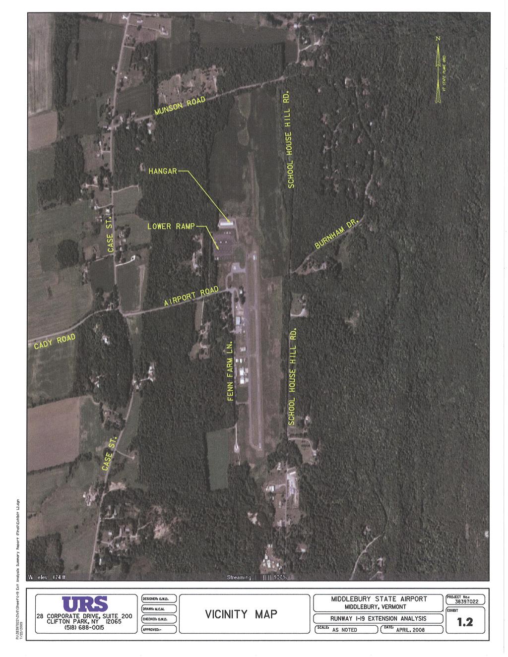
3 Final Summary Report 1.1 INTRODUCTION The Middlebury State Airport, located on the outskirts of the Village of East Middlebury, Vermont, serves the general aviation market, caters primarily to single engine aircraft, and is home to J&M Aviation, the sole Fixed Based Operator (FBO) located on the airfield (see Exhibits 1.1 and 1.2). Middlebury is a town of 8,400 people (estimated 2007 population) in Addison County. Major industries in the county include dairy farming and Middlebury College, an exclusive liberal arts college of 2,450 undergraduate students. The Middlebury Airport is located approximately 30 miles south of the Burlington International Airport and 40 miles north of the Rutland State Airport. The airfield consists of a single paved runway (1-19), which is 50 feet wide and 2,500 feet in length, approximately 87,000 square feet of apron, nine hangars, a combine terminal and maintenance building, and a full length parallel taxiway (see Exhibit 1.3). The approaches to both runways are visual. URS Corporation (URS) reviewed the Master Plan Update (2003) for the Middlebury State Airport to determine the design parameters for the proposed runway extension. Current aircraft traffic is generally small single engine aircraft, which lead to the Master Plan Update selection of the Cessna 172 as the predominant aircraft (2001). Both Federal Aviation Administration (FAA) Form and the Master Plan Update cite aviation activity in calendar year 1999 at 35,000 operations with the Master Plan forecast for moderate growth to 37,500 operations for 2004 and 40,200 operations in Historically, Middlebury State Airport has been one of the busier general aviation airports in the Vermont State System and these numbers appear reasonable. The Master Plan Update noted that the existing runway was adequate for the based aircraft. The Airport generally conforms to Aircraft Reference Code (ARC) A-I standards; however, the Master Plan noted the following non-conforming conditions: TABLE 1: NON-CONFORMING CONDITIONS EXISTING CONDITIONS ARC A-1 STANDARD Runway Width 50 feet 60 feet RSA - Runway feet wide x 150 feet beyond threshold 120 feet wide x 240 feet beyond threshold RSA - Runway feet wide x 200 feet beyond threshold 120 feet wide x 240 feet beyond ROFA - Runway feet wide x 200 feet beyond threshold 250 feet wide x 240 feet beyond threshold Source: Master Plan Update (March 2003). 2.1 OBSTRUCTION REMOVAL, RSA, AND OFA ANALYSIS The existing 14 Code of Federal Regulations (CFR) Part 77 Approach Drawings in the Master Plan Update revealed the following: RUNWAY 1: There are at least eight obstructions within the approach to Runway 1 (Exhibit 2.1). The obstructions in the Runway 1 approach appear to consist of solitary or groups of trees. Based on an understanding of the Airport property line and limits of the existing avigation easements, at least seven of these trees can be removed (cut down). Middlebury State Airport April Runway 1-19 Extension Analysis
4 Final Summary Report RUNWAY 19: The existing approach to Runway 19 was found to be clear (Exhibit 2.2). There are no obstructions on existing Airport property. RUNWAY TRANSITIONAL SURFACES: Based on a review of the 14 CFR Part 77 Surfaces Plan in the Master Plan Update, there is at least one hangar north of the existing terminal that protrudes into the Transitional Surface. RUNWAY HORIZONTAL AND CONICAL SURFACES: The 14 CFR Part 77 Imaginary Surfaces Plan in the Master Plan Update notes ground obstructions on the east side of the airfield. These ground obstructions are caused by the Green Mountains, which rise to a height of 2,000 feet MSL, approximately 1.6 miles east of the airfield. Also, the Master Plan Update revealed the following non-conforming Runway Safety Area (RSA) and Runway Object Free Area (OFA) conditions: RSA: Runway 1-19, which is included under ARC Design Group I, requires a RSA 120 feet wide (60 feet on either side of the runway centerline) and 240 feet in length beyond the runway threshold. The current RSA for Runway 1 is 120 feet in width, which meets standards, however, given the topography off the runway end and the presence of a wetland, the RSA is only 100 feet in length beyond the runway threshold. Therefore, the ALP lists the existing Runway 1 RSA as a non-conforming condition. OFA: FAA design standards require an OFA that is 250 feet wide and 240 feet beyond the runway end. As noted in the Master Plan Update, Runway 1 OFA is 250 feet in width; however it only extends 200 feet beyond the Runway 1 end due to existing obstructions (trees) OBSTRUCTION REMOVAL, RSA, AND OFA ALTERNATIVES To clear the existing obstructions to the Runway 1 14 CFR Part 77 surfaces and to provide a standard RSA and OFA for Runway 1, two alternatives were developed to determine the ideal location of the Runway 1 threshold. ALTERNATIVE 1: This alternative would relocate the Runway 1 threshold 140 feet in order to provide a RSA (120 feet by 240 feet) and OFA (250 feet by 240 feet) (see Exhibit 2.3). This alternative would not impact wetlands and, therefore, would not require wetland permitting [US Army Corps of Engineers (ACOE) or Conditional Use Determination (CUD)]; however, it will require obtaining additional easements to clear obstructions #8 and #9. ALTERNATIVE 2: This alternative would relocate the Runway 1 threshold 341 feet, which would provide a standard RSA (120 feet by 240 feet) and OFA (250 feet by 240 feet) and would clear all existing 14 CFR Part 77 obstructions off-airport property (Exhibit 2.4). This alternative would not impact wetlands or require additional easements. Middlebury State Airport April Runway 1-19 Extension Analysis
5 Final Summary Report 3.1 RUNWAY EXTENSION ANALYSIS The Master Plan Update recommended widening the existing runway from 50 feet to 60 feet and extending the runway from 2,500 feet to 3,700 feet. These parameters were selected based on the Master Plan Update forecast of the critical or design aircraft as aircraft in ARC B-I. Examples of aircraft in this ARC include: Beechcraft (King Air B-100, Baron), Cessna [Businessliner (402), Golden Eagle (421)], Mitsubishi (MU-2), Piper (Navajo, Cheyenne, Aerostar), and Rockwell (Turbo Commander). All of these aircraft are currently in use and are frequent visitors to airports in the Northeast. Many of these (or similar) aircraft are currently using the Middlebury Airport, albeit, under ideal weather conditions and at reduced weight. The FBO has indicated the larger aircraft often depart with less than a full load of fuel to reduce weight during takeoff. The Vermont Airport System Plan (VASP), which was prepared by SH&E in July 1973, designated the Middlebury State Airport as an economic development airport. Standards developed under this Plan recommended that economic development airports have a minimum length of 4,000 feet and width of 100 feet. The VASP was revised in September Middlebury State Airport is now classified as a Local Service Airport. The VASP recommends that Local Service Airports serve aircraft in ARC B-1, with minimum standards to include a runway 75 feet wide and 4,000 feet in length. Requirements for Small Airplanes with fewer than 10 Passenger Seats identified in FAA Advisory Circular 150/5325-4B (July 2005) indicate that runway length for aircraft in ARC B-1 should be between 3,100 and 3,700 feet. A length of 3,100 feet will handle approximately 95% of the aircraft feet in ARC B-1, while a runway length of 3,700 feet will handle 100% of the ARC B-I fleet. The Airport provides aeronautical services for businesses and visitors to the area, which includes the Middlebury College Campus. Based on the Master Plan Update and the VASP recommendations, the present runway length of 2,500 feet is inadequate for many aircraft operations, and does not serve the recommended role for the Airport. Both of these documents recommended widening and extending Runway RUNWAY EXTENSION ALTERNATIVES The alternatives were developed with the assumption that additional easements would not be obtained to clear obstructions (#8 and #9 cited above) within Runway 1 14 CFR Part 77 surfaces and that the Runway 1 threshold would then be relocated 341 feet at Station to provide for a standard RSA and OFA as well as clear 14 CFR Part 77 surfaces (see Exhibit 2.4). ALTERNATIVE 1: This alternative would relocate the Runway 19 threshold approximately 1,194 feet at a gradient of 0.00% (Exhibit 3.1). This alternative will require tree clearing on Airport property and acquisition of additional avigation easements to clear trees north of existing Airport property. This alternative will have a minor impact on area wetlands and will require ACOE and CUD permitting. With relocating the threshold 341 feet, the resultant runway length would be 3,359 feet. Middlebury State Airport April Runway 1-19 Extension Analysis
6 Final Summary Report ALTERNATIVE 2: This alternative would relocate the Runway 19 threshold approximately 935 feet at a gradient of 0.2% (Exhibit 3.2). This alternative will require tree clearing on Airport property, but no acquisition of additional easements or wetland impacts. With relocating the threshold 341 feet, he resultant runway length would be 3,100 feet. ALTERNATIVE 3: This alternative would relocate the Runway 19 threshold approximately 1,050 feet at a gradient of 0.7% (Exhibit 3.3). This alternative will require clearing of on Airport obstructions, but will clear the trees north of the Airport property. This alternative should have not require ACOE permits but will require a CUD from the Agency of Natural Resources for temporary work within the wetland buffer areas. With relocating the threshold 341 feet, the resultant runway length would be 3,215 feet. ALTERNATIVE 4: This alternative would relocate the Runway 19 threshold approximately 1,535 feet at a gradient of 2% (Exhibit 3.4). The 2% gradient will be required to clear the obstructions off Airport property. Note that 2% is the maximum allowable gradient for aircraft in Design Groups I and II; however, FAA Advisory Circular 150/ indicates that minimum longitudinal grades are desirable. A 2% gradient will also result in a threshold elevation approximately 45 feet above the existing ground elevation. Clearing will still be required on Airport property. With relocating the threshold 341 feet, the resultant runway length would be 3,700 feet. ALTERNATIVE 5: This alternative takes Alternative 4 above and applies the use of Declared Distances (see Exhibit 3.5). This alternative would relocate the Runway 19 threshold approximately 1,535 feet at a gradient of 2%. This option will provide 3,900 linear feet of runway pavement. Initially, the Runway 1 threshold will be placed at Station to allow a 20:1 clear approach to the south. The Runway 19 threshold will be placed at Station to provide a 20:1 clear approach to the north. Both Runways 1 and 19 will be displaced as shown on Exhibit 3.5. Displacing the thresholds as shown will provide the following usable runway lengths: TABLE 2: RUNWAY LENGTH AVAILABLE (FEET) RUNWAY 1 RUNWAY 19 LANDING 3,700 3,300 TAKEOFF 3,900 3,900 The displaced thresholds could be removed after easements are acquired and the obstructions removed. The resultant runway will be 3,900 feet in length. 4.1 FAA COMMENTS At a meeting with Vermont Agency of Transportation (VTrans) in May 2006, the FAA responded stating that extending Runway 1-19 from its current length of 2,500 feet to 3,700 feet was not satisfactorily justified in the 2003 Master Plan. Page 4-2 of this document stated: it is recommended that the necessary studies for the extension be carried out at the end of the short-term period to verify that the current aircraft fleet and operations warrant such an extension. From this statement, the FAA indicated Middlebury State Airport April Runway 1-19 Extension Analysis
7 Final Summary Report that the forecasts provided in the Master Plan do not support this proposed runway extension. In order to justify this extension, the runway length acceptable for ARC B-1 aircraft needed to be identified as well as a verification of the number of operations. As a result, action items from this meeting included the installation of acoustical (REMS) counters for Runway 1-19 by VTrans staff and the acquisition of letters of support from the community AVIATION FORECASTS As a result of the acoustical data and letters of support received, forecasts were updated prior to the preparation of the Purpose and Need and Environmental Assessment. REMS data received for the month of July 2006 recorded 483 aircraft takeoffs, which prorate to 11,592 annual operations. This number correlates reasonably with an accepted forecasting formula (based aircraft x 259 = 12,423 annual operations). Table 3 summarizes the aviation forecasts developed in the Master Plan and includes the 2006 REMS data. TABLE 3: SUMMARY OF MASTER PLAN FORECAST DATA Based Aircraft Local Operations , ,200 37,000 Itinerant Operations 7,000 7, ,000 9,200 Total Operations 35,000 37,500 11, ,200 46,200 ARC A-1 B-1 -- B-1 B-1 Sources: 1 Airport Master Plan Update- Table 3-2 and Table 3-3 (March 2003). 2 Based aircraft provided by J&M Aviation (September 2006). 3 REMS count by VTrans (483 count x 2 x 12 months = 11,592) (July 2006). J&M Aviation, the FBO, verified that there were 48 aircraft, including jet and multi-engine piston aircraft such as the Fougere Magistere, Piper Aztec, Cessna Citation and Cessna 310 based at the Airport in This number of existing based aircraft compared well with the Fleet Mix Forecasts in the Master Plan (2003), which is included in Table 4. In addition to the aircraft currently based on the airfield, other multi-engine and jet aircraft operating at Middlebury State Airport include the Piper Navaho, Piper Aztec, Piper Cheyenne, Cessna 402, and Beechcraft Baron. Middlebury State Airport April Runway 1-19 Extension Analysis
8 Final Summary Report TABLE 4: BASED AIRCRAFT FLEET MIX FORECAST Total Based Aircraft Single Engine Piston Aircraft Multi-Engine Piston Aircraft Turboprop Aircraft Jet Aircraft Rotor Aircraft Ultra-light Aircraft Glider Source: Airport Master Plan Update (March 2003) 1 Based aircraft provided by J&M Aviation (September 2006). The existing Master Plan forecasted the annual traffic growth at approximately 1.5% annually over the twenty year plan. Air traffic operations at the neighboring Rutland State Airport have increased approximately 2% annually since the year TABLE 5: PREFERRED AVIATION FORECASTS ( ) Actual Forecast Based Aircraft Local Operations 28, Itinerant Operations 7, Operations 35,000 11, Forecast Operations (Method A) ,800 14,000 Forecast Operations (Method B) ,468 14,763 Preferred Forecasts ,000 14,200 Airport Reference Code A-1 B-1 B-1 B-1 Source: URS Corporation (2007). 1 Airport Master Plan Update (March 2003). Using the 2006 data, URS developed the Aviation Forecasts cited in the Table 5 using two separate methodologies. The first methodology assumes that aviation growth at the Airport will continue at 2% annually. The second methodology assumes that the forecasts will increase in direct proportion to the based aircraft times 259. Since the results of both forecasts are similar, we are recommending the preferred forecast, as shown in Table 5. Both forecast methodologies assumed that the existing runway dimensions remain constant. These forecasts were reviewed and accepted by VTrans in February Middlebury State Airport April Runway 1-19 Extension Analysis
9 Final Summary Report LETTERS OF SUPPORT Letters in support of the recommendation for a runway extension to 3,700 feet have been received from the local community and business leaders as well as from aviation users (see Appendix). While some of these letters are of a generic content that simply imply support for the Airport; however, note that at least three of these letters are from potential Airport users, who cannot operate on the airfield due to the short runway. These operators include Worth Mountain Capital Partners, who currently charter aircraft that require a 3,700 foot runway, Eastway Aviation, a jet aircraft charter firm that serves the East coast, and Heritage Flight in Burlington, which operates King Air and Citation Aircraft. Each of these firms is unable to operate out of the Middlebury State Airport due to the limited runway length. In addition, Middlebury is home to Middlebury College, an exclusive liberal arts college. Many of its students, faculty, and trustees have access to high performance aircraft that cannot operate on the existing runway. While it is impossible to quantify this traffic potential, there would be numerous other air traffic that would use this Airport if the runway were long enough. There are many airports serving resort areas in the North Country that have better facilities and lack the traffic that currently exists at the Middlebury State Airport. Some of these airports are listed in Table 6. It would appear reasonable to expect traffic at Middlebury to mirror traffic at Morrisville-Stowe within the five to ten year time frame following construction of an extension to 3,700 feet. TABLE 6: AIRPORT COMPARISON Airport Runway Width & Length ARC Operations Based Aircraft Caledonia County State 60 x 3300 B-I 2, Parlin Field 50 x 3450 B-1 2, Middlebury State 50 x 2500 B-I 11, Morrisville-Stowe State 75 x 3701 B-II 18, Mount Washington Regional 75 x 4001 B-II 7, Lake Placid Municipal 60 x 4200 B-II 20, Ticonderoga Municipal 60 x 4040 B-I/B-II 11, Source: FAA Airport Master Record Form (1/18/07). Based on the existing traffic, potential traffic, forecast data, and support from the community, there is adequate evidence of existing unmet demand for a longer runway at the Middlebury State Airport. Construction of an extension to 3,100 feet (minimum for ARC B-I aircraft) will allow for some of the additional traffic to use this runway; however, there is doubt that this length will be sufficient to service all potential users, whereas an extension to 3,700 feet has the support of all users. 5.1 CONCLUSION The FAA indicated that they would support a 3,200 foot runway as the maximum recommended length for the Middlebury State Airport, based on the existing aviation forecasts, while both VTrans and the Middlebury Airport Committee have endorsed the Preferred Alternative (refer back to Exhibit 3.5) Middlebury State Airport April Runway 1-19 Extension Analysis
10 Final Summary Report On June 1, 2007, URS forwarded a letter to Richard Doucette requesting that the Environmental Assessment continue as originally scoped for Runway 1-19 with an ultimate length of 3,700 feet. In an response, the FAA has concurred in this request; however, the FAA has concluded that at this time they are not obligating the FAA to commit funding a runway extension beyond 3,200 feet. Middlebury State Airport April Runway 1-19 Extension Analysis
11
12
13 AIRPORT DATA EXISTING ULTIMATE EXISTING ULTIMATE BUILDINGS RUNWAY PROTECTION ZONE (RPZ) DIMENSIONS AIRPORT ELEVATION T-HANGAR 200 LENGTH AIRPORT REFERENCE POINT N 43%%d 59 08" FUEL FARM E 73%%d 05 44" HANGAR MEAN MAX. TEMP. (HOTTEST MO.) 80%%d F TERMINAL HANGAR TAXIWAY LIGHTING -- HANGARS INNER OUTER TAXIWAY MARKING -- T-HANGARS WIDTH WIDTH AIRPORT/TERMINAL NAVAIDS None DOWNEY CORP. MAINTENANCE HANGAR DOWNEY CORP. MAINTENANCE HANGAR END OF RUNWAY AIRPORT REFERENCE CODE (ARC) B-I EXISTING ULTIMATE TERMINAL AREA PAVEMENT ACREAGE OWNED IN FEE SIMPLE 156 Acres LOWER RAMP ACREAGE OWNED IN EASEMENT USE/OWNERSHIP 6 Acres General Aviation/State FUEL APRON UPPER RAMP RUNWAY APPROACH TYPE INNER WIDTH OUTER WIDTH LENGTH ACRES AUTO PARKING R/W 1 R/W 19 Visual Visual RUNWAY DATA EXISTING ULTIMATE 1 19 PAVEMENT STRENGTH 12,500 SW 12,500 SW APPROACH SURFACES Visual 20:1 Visual 20:1 NOTE: RUNWAY MARKINGS Visual Visual BUILDING RESTRICTION LINE (BRL) WAS ESTABLISHED IN RUNWAY LIGHTING None None ACCORDANCE WITH FAA DESIGN AND FAR PART 77 CRITERIA. ITS LOCATION UTILIZES A 30 FT. VERTICAL OBJECT HEIGHT. RUNWAY NAVAIDS None None THE BRL LOCATION MAY CHANGE DUE TO GROUND CONTOURS OR DIFFERENT OBJECT HEIGHTS, BUT ALWAYS IN ACCORDANCE WITH FAR PART 77 AND FAA DESIGN CRITERIA. EFFECTIVE GRADIENT 0.3%%% RUNWAY END ELEVATIONS RUNWAY END COORDINATES N 43%%d 58 55" N 43%%d 59 20" W 73%%d 05 43" W 73%%d 05 44" RUNWAY LENGTH RUNWAY WIDTH EXISTING AIRPORT PROPERTY LINE EXTENDED RSA NO YES COMPLIANCE AVIGATION EASEMENT RUNWAY PROTECTION ZONE 20:1 VISUAL APPROACH SURFACE RUNWAY PROTECTION ZONE 20:1 VISUAL APPROACH SURFACE AVIGATION EASEMENT EXISTING RUNWAY 1-19 PLAN NOTES: 1. HORIZONTAL DATUM NAD 83 (1986) INTERNATIONAL FEET. 2. VERTICAL DATUM NAVD 88 IINTERNATIONAL FEET 3. EXISTING EASEMENT AND PROPERTY LINES BASED ON "AIRPORT PROPERTY MAP" PREPARED FOR VAOT BY CLOUGH REPRINTED FROM SHEET AIRPORT MASTERPLAN UPDATE, PREPARED BY DUFRESNE-HENRY, INC. Scale: AS SHOWN Date: April, 2008 EXHIBIT Of SCALE HARBOUR ASSOCIATES, MARCH EXHIBIT 1.3
14 0 REPRINTED FROM SHEET AIRPORT MASTERPLAN UPDATE, PREPARED BY DUFRESNE-HENRY, INC Scale: AS SHOWN SCALE Date: April, 2008 EXHIBIT Of EXHIBIT 2.1
15 0 REPRINTED FROM SHEET AIRPORT MASTERPLAN UPDATE, PREPARED BY DUFRESNE-HENRY, INC Scale: AS SHOWN 100 SCALE 0 Date: April, 2008 EXHIBIT Of EXHIBIT 2.2
16 EXISTING AIRPORT PROPERTY LINE ROFA 4 RSA RSA ROFA TAXIWAY EXISTING RUNWAY 01 THRESHOLD STA , ELEV. = WETLANDS PROPOSED RUNWAY EXISTING AIRPORT PROPERTY LINE SCALE EXISTING RUNWAY PROFILE RSA PROPOSED RUNWAY 01 APPROACH PROFILE NOTES: LEGEND EXISTING AIRPORT PROPERTY LINE 100 Scale: AS SHOWN 1.) OBSTRUCTIONS 1, 2, 5 AND 7 POSSIBLY LIE WITHIN THE AVIGATION EASEMENT. LIMIT OF DELINEATED WETLANDS Date: April, ) OBSTRUCTION 3 ARE ON AIRPORT PROPERTY. 3.) OBSTRUCTION 6 ON AIRPORT PROPERTY OR AVIGATION EASEMENT. EDGE OF RUNWAY PROTECTION ZONE (RPZ) 50 EXHIBIT Of RUNWAY OBJECT FREE AREA (ROFA) 4.) OBSTRUCTIONS 8 AND 9 ARE OFF AIRPORT PROPERTY, NOT IN AVIGATION EASEMENT EXHIBIT 5.) WETLANDS DELINEATED BY THE SMART ASSOCIATES, INC. NOVEMBER 2005 RUNWAY SAFETY AREA (RSA) 2.3 SCALE
17 EXISTING AIRPORT PROPERTY LINE ROFA 4 RSA RSA ROFA TAXIWAY EXISTING RUNWAY 01 THRESHOLD STA , ELEV. = WETLANDS PROPOSED RUNWAY EXISTING AIRPORT PROPERTY LINE SCALE EXISTING RUNWAY PROFILE PROPOSED RUNWAY 01 APPROACH PROFILE NOTES: LEGEND EXISTING AIRPORT PROPERTY LINE 100 Scale: AS SHOWN 1.) OBSTRUCTIONS 1, 2, 5 AND 7 POSSIBLY LIE WITHIN THE AVIGATION EASEMENT. LIMIT OF DELINEATED WETLANDS Date: April, ) OBSTRUCTION 3 IS ON AIRPORT PROPERTY. 3.) OBSTRUCTION 6 ON AIRPORT PROPERTY OR AVIGATION EASEMENT. EDGE OF RUNWAY PROTECTION ZONE (RPZ) 50 EXHIBIT Of 4.) OBSTRUCTIONS 8 AND 9 ARE OFF AIRPORT PROPERTY, NOT IN AVIGATION EASEMENT. 5.) WETLANDS DELINEATED BY THE SMART ASSOCIATES, INC. NOVEMBER 2005 RUNWAY OBJECT FREE AREA (ROFA) RUNWAY SAFETY AREA (RSA) SCALE EXHIBIT 2.4
18 EXISTING AIRPORT PROPERTY LINE 1000 RPZ SNOW MOBILE TRAIL MARKERS EXISTING AIRPORT PROPERTY LINE WETLANDS 240 RSA HANGAR PROPOSED RUNWAY 19 PLAN LOWER RAMP SCALE LEGEND 100 Scale: AS SHOWN PROPOSED RUNWAY 19 APPROACH PROFILE EXISTING AIRPORT PROPERTY LINE NOTES: 1.) OBSTRUCTIONS 10, 11, 12 AND 13 ARE ON AIRPORT PROPERTY 2.) OBSTRUCTIONS 14 AND 15 ARE ON APPROXIMATE EDGE OF AIRPORT PROPERTY LIMIT OF DELINEATED WETLANDS EDGE OF RUNWAY PROTECTION ZONE (RPZ) 50 Date: April, 2008 EXHIBIT Of 3.) WETLANDS DELINEATED BY SMART ASSOCIATES, NOVEMBER 2005 RUNWAY OBJECT FREE AREA (ROFA) RUNWAY SAFETY AREA (RSA) SCALE 0 EXHIBIT 3.1
19 EXISTING AIRPORT PROPERTY LINE EXISTING AIRPORT PROPERTY LINE 1000 RPZ 14 ROFA RSA RSA ROFA WETLANDS RSA SNOW MOBILE TRAIL MARKERS HANGAR PROPOSED RUNWAY 19 PLAN LOWER RAMP SCALE PROPOSED RUNWAY 19 APPROACH PROFILE LEGEND EXISTING AIRPORT PROPERTY LINE 100 Scale: AS SHOWN Date: April, 2008 NOTES: 1.) OBSTRUCTIONS 10, 11, 12 AND 13 ARE ON AIRPORT PROPERTY LIMIT OF DELINEATED WETLANDS EDGE OF RUNWAY PROTECTION ZONE (RPZ) 50 EXHIBIT Of 2.) OBSTRUCTIONS 14 AND 15 ARE ON APPROXIMATE EDGE OF AIRPORT PROPERTY EXHIBIT RUNWAY OBJECT FREE AREA (ROFA) ) WETLANDS DELINEATED BY SMART ASSOCIATES, NOVEMBER RUNWAY SAFETY AREA (RSA) 3.2 SCALE
20 EXISTING AIRPORT PROPERTY LINE EXISTING AIRPORT PROPERTY LINE 1000 RPZ 14 ROFA RSA RSA ROFA WETLANDS RSA SNOW MOBILE TRAIL MARKERS HANGAR PROPOSED RUNWAY 19 PLAN LOWER RAMP SCALE PROPOSED RUNWAY 19 APPROACH PROFILE LEGEND EXISTING AIRPORT PROPERTY LINE 100 Scale: AS SHOWN Date: April, 2008 NOTES: 1.) OBSTRUCTIONS 10, 11, 12 AND 13 ARE ON AIRPORT PROPERTY LIMIT OF DELINEATED WETLANDS EDGE OF RUNWAY PROTECTION ZONE (RPZ) 50 EXHIBIT Of 2.) OBSTRUCTIONS 14 AND 15 ARE ON APPROXIMATE EDGE OF AIRPORT PROPERTY EXHIBIT RUNWAY OBJECT FREE AREA (ROFA) ) WETLANDS DELINEATED BY SMART ASSOCIATES, NOVEMBER RUNWAY SAFETY AREA (RSA) SCALE
21 EXISTING AIRPORT PROPERTY LINE EXISTING AIRPORT PROPERTY LINE 1000 RPZ 14 ROFA RSA RSA ROFA RSA WETLANDS SNOW MOBILE TRAIL MARKERS HANGAR PROPOSED RUNWAY 19 PLAN LOWER RAMP SCALE PROPOSED RUNWAY 19 APPROACH PROFILE LEGEND EXISTING AIRPORT PROPERTY LINE 100 Scale: AS SHOWN Date: April, 2008 NOTES: 1.) OBSTRUCTIONS 10, 11, 12 AND 13 ARE ON AIRPORT PROPERTY LIMIT OF DELINEATED WETLANDS EDGE OF RUNWAY PROTECTION ZONE (RPZ) 50 EXHIBIT Of 2.) OBSTRUCTIONS 14 AND 15 ARE ON APPROXIMATE EDGE OF AIRPORT PROPERTY EXHIBIT RUNWAY OBJECT FREE AREA (ROFA) ) WETLANDS DELINEATED BY SMART ASSOCIATES, NOVEMBER RUNWAY SAFETY AREA (RSA) SCALE
22 RSA RSA HANGAR LOWER RAMP EXISTING AIRPORT PROPERTY LINE RUNWAY 1-19 PLAN SCALE LEGEND EXISTING AIRPORT PROPERTY LINE LIMIT OF DELINEATED WETLANDS EDGE OF RUNWAY PROTECTION ZONE (RPZ) RUNWAY 1 (FEET) RUNWAY 19 (FEET) RUNWAY 1-19 PROFILE Scale: AS SHOWN RUNWAY PRIMARY SURFACE LANDING SCALE Date: April, 2008 RUNWAY SAFETY AREA (RSA) TAKEOFF EXHIBIT Of SLOPE LIMITS LIMITS OF IMPACTED WETLANDS EXHIBIT 3.5
23
24
25
26
27
28
29
30
31
32
33
34
35
36
37
38
39
40
41
Chapter Six ALP Drawings. Tacoma Narrows Airport. Master Plan Update
 Chapter Six ALP Drawings Master Plan Update The master planning process for the (Airport) has evolved through efforts in the previous chapters to analyze future aviation demand, establish airside and landside
Lopez Island Airport Master Plan Update. Public Meeting June 15, 2017
 Lopez Island Airport Master Plan Update Public Meeting June 15, 2017 Master Plan Update Team Reid Middleton/Everett, WA Shannon Kinsella, Project Manager Melania Haagsma, Project Engineer Mead & Hunt/Tulsa,
Chapter 4 Airport Facility Requirements
 Chapter 4 Airport Facility Requirements Introduction CHAPTER 4 AIRPORT FACILITY REQUIREMENTS MAY 2013-1 Organization of Materials CHAPTER 4 AIRPORT FACILITY REQUIREMENTS MAY 2013-2 RPZ - ROAD RPZ - NON-AIRPORT
AIRSIDE CAPACITY AND FACILITY REQUIREMENTS
 AIRSIDE CAPACITY AND FACILITY REQUIREMENTS This Section investigates the capacity of the airport, its ability to meet current demand, and the facilities required to meet forecasted needs as established
DRAFT MASTER PLAN UPDATE
 DRAFT MASTER PLAN UPDATE CHAPTER VI: AIRPORT LAYOUT PLAN NARRATIVE DRAFT REPORT APRIL 2017 PREPARED BY: Table of Contents WESTCHESTER COUNTY AIRPORT 6 AIRPORT LAYOUT PLAN NARRATIVE REPORT... 6-1 6.1 AGIS
New Opportunities PUBLIC WORKSHOP. Venice Municipal. Bringing g the pieces together
 Bringing g the PUBLIC WORKSHOP Venice Municipal Airport New Opportunities Presented for Venice City Council & Citizens of Venice September 25, 2009 Slide 1 Bringing g the Welcome & Introductions May 12th
TECHNICAL REPORT #7 Palm Beach International Airport Airport Layout Plan
 TECHNICAL REPORT #7 Palm Beach International Airport Airport Layout Plan Technical Report #7 Palm Beach International Airport Layout Plan Palm Beach International Airport Prepared for Palm Beach County
CHAPTER 1 EXECUTIVE SUMMARY
 CHAPTER 1 EXECUTIVE SUMMARY 1 1 EXECUTIVE SUMMARY INTRODUCTION William R. Fairchild International Airport (CLM) is located approximately three miles west of the city of Port Angeles, Washington. The airport
CHAPTER 1 BACKGROUND AND PROPOSED ACTION
 CHAPTER 1 BACKGROUND AND PROPOSED ACTION 1.0 INTRODUCTION An Environmental Assessment (EA) evaluates the effects of a proposed Federal action on the surrounding environment and is prepared in compliance
Technical Advisory Committee Meeting February 29, 2016
 Technical Advisory Committee Meeting February 29, 2016 Meeting Agenda Introduction Recap of Planning Process Project Status Goals and Objectives Forecasts of Aviation Demand Overview of Facility Requirements
AIRPORT LAYOUT PLAN FOR FRIEDMAN MEMORIAL REPLACEMENT AIRPORT - SITE 12 FRIEDMAN MEMORIAL AIRPORT AUTHORITY INDEX OF SHEETS SHEET TITLE
 GOODING MUNICIPAL SOURCE: JeppView 3.6.3.1 (Printed May 19, 2010) MAGIC VALLEY REGIONAL BURLEY MUNICIPAL LOCATION MAP NTS - SITE 12 AIRPORT LAYOUT PLAN FOR FRIEDMAN MEMORIAL REPLACEMENT AIRPORT - SITE
FACILITY REQUIREMENTS 5.1 Introduction
 Chapter 5 FACILITY REQUIREMENTS 5.1 Introduction The facility requirements section of this study defines the physical facilities needed to safely and efficiently accommodate the current and future aviation
CHAPTER 3 ALTERNATIVES CONSIDERED
 CHAPTER 3 ALTERNATIVES CONSIDERED 3.0 ALTERNATIVES The 2010 Stevensville Airport Master Plan contained five (5) airside development options designed to meet projected demands. Each of the options from
Appendix C AIRPORT LAYOUT PLANS
 Appendix C AIRPORT LAYOUT PLANS Appendix C AIRPORT LAYOUT PLANS Airport Master Plan Santa Barbara Airport As part of this Airport Master Plan, the Federal Aviation Administration (FAA) requires the development
Chapter 9 - AIRPORT SYSTEM DESIGN
 Chapter 9 - AIRPORT SYSTEM DESIGN 9.01 GENERAL This chapter discusses the development program for Dutchess County Airport to the year 2020. This airport system design is based upon the airport's existing
CHAPTER 3 AIRPORT FACILITY REQUIREMENTS
 CHAPTER 3 AIRPORT FACILITY REQUIREMENTS 3.1 Introduction The existing runway and taxiway system at Skyhaven Airport provides more than adequate operational capacity to accommodate future peak hour and
FACILITY REQUIREMENTS SUMMARY OF KEY ISSUES OVERVIEW
 FACILITY REQUIREMENTS SUMMARY OF KEY ISSUES OVERVIEW This summary is intended to provide a brief overview of the key issues associated with conformance to FAA standards at Methow Valley State Airport.
Table of Contents. Overview Objectives Key Issues Process...1-3
 Table of Contents Chapter One Introduction Overview...1-1 Objectives...1-1 Key Issues...1-2 Process...1-3 Chapter Two Inventory of Existing Conditions Airport Setting...2-1 Locale...2-1 Airport Surroundings...2-5
Merritt Island Airport
 TABLE OF CONTENTS CHAPTER 1 INTRODUCTION... 1-1 INTRODUCTION AND PROJECT OVERVIEW... 1-1 General Guidelines... 1-1 Prior Planning Documentation... 1-2 Key Issues... 1-2 Goals and Objectives... 1-2 Regulatory
Technical Memorandum. Synopsis. Steve Carrillo, PE. Bryan Oscarson/Carmen Au Lindgren, PE. April 3, 2018 (Revised)
") Appendix D Orange County/John Wayne Airport (JWA) General Aviation Improvement Program (GAIP) Based Aircraft Parking Capacity Analysis and General Aviation Constrained Forecasts Technical Memorandum To:
Appendix D Orange County/John Wayne Airport (JWA) General Aviation Improvement Program (GAIP) Based Aircraft Parking Capacity Analysis and General Aviation Constrained Forecasts Technical Memorandum To:
8.0 AIRPORT LAYOUT PLANS
 8.0 AIRPORT LAYOUT PLANS This chapter presents a detailed graphic and narrative description of the selected development concept for General Mitchell International Airport (MKE). The plans package presented
OVERVIEW BASIC DESIGN FACTORS. Demand Determinants
 3 Airfield Airfield Design Design OVERVIEW The basic configuration of the runway and taxiway system at Hanford Municipal Airport has changed moderately since the airport was constructed in 1950. These
Preliminary Findings of Proposed Alternative
 Preliminary Findings of Proposed Alternative The attached drawing provides a schematic layout of the proposed alternative that will be discussed on July 27, 2010. A full report will follow and should be
MASTER PLAN CONCEPT 1 DRAFT
 The Airport Master Plan Update for Dallas Executive Airport has included the development of aviation demand forecasts, an assessment of future facility needs, and the evaluation of airport development
Dallas Executive Airport Town Hall Meeting April 3, 2014
 Dallas Executive Airport Town Hall Meeting April 3, 2014 Background 1,040 acre general aviation facility owned and operated by the City of Dallas 150 based aircraft including business jets and helicopters,
Master Plan Update Technical Advisory Committee Meeting
 Nashville International Airport Master Plan Update Technical Advisory Committee Meeting February 14, 2019 Agenda Welcome and Introductions Aviation Activity Forecast Facility Requirements Alternatives
TABLE OF CONTENTS. General Study Objectives Public Involvement Issues to Be Resolved
 TABLE OF CONTENTS Description Page Number LIST OF ACRONYMS... a CHAPTER ONE INTRODUCTION General... 1-1 Study Objectives... 1-1 Public Involvement... 1-2 Issues to Be Resolved... 1-2 CHAPTER TWO EXISTING
Chapter 5. Facility Requirements
 Chapter 5 Facility Requirements Chapter 5 Facility Requirements INTRODUCTION The Baseline Forecast was used to determine facility requirements. Chapter 4 produced a forecast of traffic volumes expected
General Aviation Master Plan Update
 Peter O. Knight Airport Public Meeting #2 Peter O. Knight Airport Agenda Welcome and Introductions HCAA System of Airports Purpose of Public Meetings Master Plan Status Update Next Steps Q & A 2 Our System
Appendix C. User Survey Data
 Appendix C User Survey Data Charlevoix Municipal Airport Master Plan APPENDIX C: 2010 USER SURVEY SUMMARY In support of the 2010 Master Planning effort for Charlevoix Municipal Airport (CVX), an aviation
Background Data: Blue Canyon Airport and Environs
 5 Background Data: and Environs INTRODUCTION serves as an important emergency landing field amid mountainous terrain. The airport has existed on the site since the 1930s or 40s. The facility was operated
5. Facility Requirements
 5. Facility Requirements The purpose of this chapter is to compare existing airfield and adjacent landside facilities with the Airport operations and aircraft forecasts developed in the previous chapter
15 Precision Approach Path Indicator 33 None RSA 150 feet wide by 300 feet long 150 feet wide by 300 feet long
 The first (AMP) was completed in 1984 and updated in 2000. The current FAA approved Airport Layout Plan (ALP) is dated November 9, 2001. The FAA suggests updating the AMP every five year in accordance
Friedman Memorial Airport Authority. Regular Meeting September 4, 2012
 Friedman Memorial Airport Authority Regular Meeting September 4, 2012 UNFINISHED BUSINESS Airport Solutions Blaine County Report Airport Solutions City of Hailey Report Airport Solutions Airport Manager
APPENDIX X: RUNWAY LENGTH ANALYSIS
 APPENDIX X: RUNWAY LENGTH ANALYSIS Purpose For this Airport Master Plan study, the FAA has requested a runway length analysis to be completed to current FAA AC 150/5325-4B, Runway Length Requirements for
3 INTRODUCTION. Chapter Three Facility Requirements. Facility Requirements PEAKING CHARACTERISTICS
 Chapter Three Facility Requirements 3 INTRODUCTION This chapter identifies the long-range airfield and terminal area facilities needed to satisfy the 20-year forecast of aviation demand at Monett Municipal
1.0 Project Background Mission Statement and Goals Objectives of this Sustainable Master Plan
 TABLE OF CONTENTS CHAPTER 1 INTRODUCTION 10 Project Background 1-1 11 Mission Statement and Goals 1-1 12 Objectives of this Sustainable Master Plan 1-2 CHAPTER 2 INVENTORY 20 Airport Background 2-1 201
Chapter 4 Airport Facility Requirements
 Chapter 4 Airport Facility Requirements The evaluation of airport facility requirements uses the results of the inventory and forecasts contained in Chapters Two and Three, as well as established planning
Tallahassee International Airport Master Plan. Technical Advisory Committee Meeting #2 October 19, 2016
 Tallahassee International Airport Master Plan Technical Advisory Committee Meeting #2 October 19, 2016 Agenda Welcome / Introductions Master Plan Process and Project Status Forecast of Aviation Demand
PLU Airport Master Plan. Master Plan Advisory Committee (MPAC) Meeting #4 March 19, 2018
 Meeting #4 March 19, 2018") PLU Airport Master Plan Master Plan Advisory Committee (MPAC) Meeting #4 March 19, 2018 Meeting Agenda 1. Master Plan Status [5 Minutes] 2. Preferred Forecasts [15 Minutes] 3. Runway Length Options [45
PLU Airport Master Plan Master Plan Advisory Committee (MPAC) Meeting #4 March 19, 2018 Meeting Agenda 1. Master Plan Status [5 Minutes] 2. Preferred Forecasts [15 Minutes] 3. Runway Length Options [45
DRAFT FINAL REPORT AIRPORT MASTER PLAN. Rifle Garfield County Airport Revised May 15, 2014
 DRAFT FINAL REPORT AIRPORT MASTER PLAN Rifle Garfield County Airport Revised May 15, 2014 As required by Paragraph 425.B(4) of FAA Order 5100.38C, Airport Improvement Program (AIP) Handbook: The preparation
CHAPTER 5 - FACILITY REQUIREMENTS
 CHAPTER 5 - FACILITY REQUIREMENTS This chapter identifies the requirements for airfield and landside facilities to accommodate the forecast demand level. Facility requirements have been developed for the
Chapter 5 Airport Facility Requirements
 Chapter 5 Airport Facility Requirements Introduction The evaluation of airport facility requirements uses the results of the inventory and forecasts contained in Chapters Two and Three, as well as established
Safety, Infrastructure, and Tenant Improvement Project. Public Hearing Informational Brochure February 26, 2013
 New York State Department of Transportation Safety, Infrastructure, and Tenant Improvement Project Public Hearing Informational Brochure February 26, 2013 This DEIS/Draft EA evaluates the potential impacts
Airfield Design. Public Review Draft OVERVIEW BASIC DESIGN FACTORS. Airport Role
 Public Review Draft 3 Airfield Design OVERVIEW The Facilities Plan, Figure 3D, presents the recommended airfield improvements. The principal airfield design issues examined in this chapter are the optimal
Table of Contents. List of Tables. Cincinnati/Northern Kentucky International Airport 2035 Master Plan Update
 Table of Contents 7.1. Airport Layout Plan (Existing Conditions)... 2 7.2. Airport Layout Plan (Future Conditions)... 3 7.3. Technical Data Sheet... 5 7.4. Commercial Terminal Area Drawing... 5 7.5. East
FORT LAUDERDALE-HOLLYWOOD INTERNATIONAL AIRPORT ENVIRONMENTAL IMPACT STATEMENT DRAFT
 D.3 RUNWAY LENGTH ANALYSIS Appendix D Purpose and Need THIS PAGE INTENTIONALLY LEFT BLANK Appendix D Purpose and Need APPENDIX D.3 AIRFIELD GEOMETRIC REQUIREMENTS This information provided in this appendix
Runway Length Analysis Prescott Municipal Airport
 APPENDIX 2 Runway Length Analysis Prescott Municipal Airport May 11, 2009 Version 2 (draft) Table of Contents Introduction... 1-1 Section 1 Purpose & Need... 1-2 Section 2 Design Standards...1-3 Section
Background Data: Blue Canyon Airport and Environs
 Chapter 8 Background ata: and Environs Placer County Airport Land Use Compatibility Plan 8 Background ata: and Environs INTROUCTION serves as an important emergency landing field amid mountainous terrain.
DATE OF AERIAL PHOTOGRAPHY:
 DESCRIPTION RUNWAY SAFETY AREA RUNWAY PROTECTION ZONE TAXIWAY OBJECT FREE AREA DATE OF AERIAL PHOTOGRAPHY: 6-17-01 RUNWAY SAFETY AREA FOR PORTION OF RUNWAY 16L-34R SOUTH OF RUNWAY BRIDGE HAS A FAA WAIVER
chapter 5 Recommended Master Plan Concept airport master plan MASTER PLAN CONCEPT
 chapter 5 Recommended Master Plan Concept airport master plan The planning process for Coolidge Municipal Airport has included several analytical efforts in the previous chapters intended to project potential
Chapter 4.0 Alternatives Analysis
 Chapter 4.0 Alternatives Analysis Chapter 1 accumulated the baseline of existing airport data, Chapter 2 presented the outlook for the future in terms of operational activity, Chapter 3 defined the facilities
AIRPORT LAYOUT PLAN FUTURE LEGEND: REVISIONS BUILDING AIRPORT PROPERTY RUNWAY PROTECTION ZONE (RPZ) AIRCRAFT PAVEMENT
 AIRCRAFT PAVEMENT") AIRPORT LAYOUT PLAN STORM LAKE MUNICIPAL AIRPORT (SLB) 13 10.5 KNOTS FAA APPROVAL LETTER STORM LAKE, IA STORM LAKE MUNICIPAL AIRPORT $ LOCATION MAP $ ALL WEATHER WINDROSE STORM LAKE MUNICIPAL AIRPORT US
AIRPORT LAYOUT PLAN STORM LAKE MUNICIPAL AIRPORT (SLB) 13 10.5 KNOTS FAA APPROVAL LETTER STORM LAKE, IA STORM LAKE MUNICIPAL AIRPORT $ LOCATION MAP $ ALL WEATHER WINDROSE STORM LAKE MUNICIPAL AIRPORT US
EXHIBIT A. LOMPOC AIRPORT MASTER PLAN SCOPE OF WORK AIP Project #
 EXHIBIT A LOMPOC AIRPORT MASTER PLAN SCOPE OF WORK AIP Project # 3-06-0125-11 INTRODUCTION The following proposed work program for the Lompoc Airport Master Plan describes in detail the work which is to
Chapter 4.0 Facility Requirements
 Chapter 4.0 Facility Requirements Having inventoried the existing infrastructure and forecasted demand, determining airport facility requirements is the next essential step in the airport master planning
Airport Master Plan. Brookings Regional Airport. Runway Runway 17-35
 Runway 17-35 Airport Master Plan Runway 12-30 Brookings Regional Airport Table of Contents Table of Contents Chapter 1: Master Plan Goals... 1-1 1.1. Introduction... 1 1.2. Objective 1 Identify improvements
STUDY WORK GROUP MEETING No. 3. November 29, 2016
 STUDY WORK GROUP MEETING No. 3 November 29, 2016 Agenda Welcome and introductions Update project schedule Brief overview of previous SWG meeting Update on aviation forecasts Introduction to airfield demand/capacity
ERIE INTERNATIONAL AIRPORT MASTER PLAN TABLE OF CONTENTS
 EXECUTIVE SUMMARY ERIE INTERNATIONAL AIRPORT MASTER PLAN TABLE OF CONTENTS PAGE NO. CHAPTER 1-INTRODUCTION... 1-1 1.01 General...1-1 1.02 Purpose and Scope of Study...1-1 1.03 The Planning Process...1-2
Acronyms. Airport Layout Plan Report Appendix A A-1
 Appendix A Acronyms AC... Advisory Circular ADG... Airplane Design Group ADO... Airport District Office AGL... Above Ground Level AIM... Aeronautical Information Manual AIP... Airport Improvement Program
Document prepared by MnDOT Office of Aeronautics and HNTB Corporation. MINNESOTA GO STATE AVIATION SYSTEM PLAN
 LAST UPDATE JULY 2013 Acknowledgements The preparation of this document was financed in part by a grant from the Federal Aviation Administration (Project No: 3-27-0000-07-10), with the financial support
Chapter 4 Facility Requirements
 Chapter 4 Facility Requirements Introduction This chapter evaluates the existing airport facilities and identifies improvements needed to effectively meet the forecasted demand levels discussed in the
Chapter 4 Airport Facility Requirements. Introduction
 Chapter 4 Airport Facility Requirements Introduction The airport facility requirements analysis combines the results of the inventory and forecasts contained in Chapters Two and Three, and the applicable
Grants Pass Airport Master Plan & Airport Layout Plan Update
 Attendees: Grants Pass Airport Master Plan & Airport Layout Plan Update Meeting #3 January 26, 2010 Merlin Community Center 100 Acorn Street, Merlin 5:45 7:15 p.m. Josephine County Department of Airports:
CHAPTER 6 ALTERNATIVES ANALYSIS
 CHAPTER 6 ALTERNATIVES ANALYSIS 6 6 ALTERNATIVES ANALYSIS INTRODUCTION The purpose of this chapter is to identify and evaluate alternative development strategies for long-range development planning at
The offers operators increased capacity while taking advantage of existing airport infrastructure. aero quarterly qtr_03 10
 The 747 8 offers operators increased capacity while taking advantage of existing airport infrastructure. 14 aero quarterly qtr_03 10 Operating the 747 8 at Existing Airports Today s major airports are
Facility Requirements
 C H A P T E R T H R E E Facility Requirements 3.0 OVERVIEW Airport planning for facility requirements is based upon addressing any existing issues and accommodating the probable demand that may occur over
PORT OF PORTLAND. Chapter Four AVIATION FACILITY REQUIREMENTS
 PORT OF PORTLAND Chapter Four AVIATION FACILITY REQUIREMENTS CHAPTER FOUR PORT OF PORTLAND AVIATION FACILITY REQUIREMENTS In this chapter, existing components of the airport are evaluated to identify the
Draft Concept Alternatives Analysis for the Inaugural Airport Program September 2005
 Draft Concept Alternatives Analysis for the Inaugural Airport Program September 2005 Section 3 - Refinement of the Ultimate Airfield Concept Using the Base Concept identified in Section 2, IDOT re-examined
Appendix D Project Newsletters. Tacoma Narrows Airport. Master Plan Update
 Appendix D Project Newsletters Tacoma Narrows Airport Master Plan Update This appendix contains the newsletters distributed throughout the project. These newsletters provided updates and information on
AIRPORT MASTER PLAN UPDATE
 AIRPORT MASTER PLAN UPDATE PENSACOLA INTERNATIONAL AIRPORT Technical Advisory Committee Meeting #2 June 20, 2017 Agenda» Introduction» Facility Requirements Airside Terminal Landside General Aviation Cargo
2015 PURDUE ROAD SCHOOL March 11, 2015
 2015 PURDUE ROAD SCHOOL March 11, 2015 Runway Protection Zone (RPZ) Definition It is a trapezoidal shape formed off the end of a runway and its geometry it a function of the airport s aircraft approach
Airport Master Plan Update
 Duttchessss Countty Airrporrtt Masstterr Plan Updatte Airport Master Plan Update Final Report Dutchess County Airport Town of Wappingers, New York C&S Engineers, Inc. 499 Col. Eileen Collins Blvd. Syracuse,
APPENDIX H 2022 BASELINE NOISE EXPOSURE CONTOUR
 APPENDIX H 2022 BASELINE NOISE EXPOSURE CONTOUR This appendix sets forth the detailed input data that was used to prepare noise exposure contours for 2022 Baseline conditions. H.1 DATA SOURCES AND ASSUMPTIONS
Hartford-Brainard Airport Potential Runway Closure White Paper
 Hartford-Brainard Airport Potential Runway 11-29 Closure White Paper June 2012 In recent years there has been discussion regarding the necessity of Runway 11-29 to the Hartford- Brainard Airport (HFD)
PLU Airport Master Plan Master Plan Advisory Committee (MPAC) Meeting #4 MASTER PLAN ADVISORY COMMITTEE (MPAC) - MEETING #4
 Meeting #4 MASTER PLAN ADVISORY COMMITTEE (MPAC) - MEETING #4") MASTER PLAN ADVISORY COMMITTEE (MPAC) - MEETING #4 MASTER PLAN ADVISORY COMMITTEE (MPAC) MEETING #4 AGENDA & ACTION ITEMS Date/Time: Location: Monday, March 19, 2018 from 1:30-3:30 p.m. Thun Field Airport
MASTER PLAN ADVISORY COMMITTEE (MPAC) - MEETING #4 MASTER PLAN ADVISORY COMMITTEE (MPAC) MEETING #4 AGENDA & ACTION ITEMS Date/Time: Location: Monday, March 19, 2018 from 1:30-3:30 p.m. Thun Field Airport
The following criteria shall be applied within the boundaries of the AO District:
 Sec. 419 (a) Purpose AIRPORT OVERLAY DISTRICT (AO) The purpose of the Airport Overlay District is to regulate and restrict the height of structures, objects, or natural growth, regulate the locations of
Chapter Three AIRPORT FACILITY REQUIREMENTS/ALTERNATIVES
 Chapter Three AIRPORT FACILITY REQUIREMENTS/ALTERNATIVES Airport Layout Plan Report In this chapter, existing components of the Airport are evaluated so that the capacities of the overall system are identified.
1 DRAFT. General Aviation Terminal Services Aircraft Hangars Aircraft Parking Aprons Airport Support Facilities
 To properly plan for improvements at Dallas Executive Airport, it is necessary to translate forecast aviation demand into the specific types and quantities of facilities that can adequately serve the demand.
5.0 ALTERNATIVES ANALYSIS
 5.0 ALTERNATIVES ANALYSIS The Alternative Analysis chapter describes and evaluates the various development alternatives considered for. In addition, it presents a preferred development plan that accommodates
SECTION 4 DEMAND/CAPACITY ANALYSIS AND FACILITY REQUIREMENTS
 SECTION 4 DEMAND/CAPACITY ANALYSIS AND FACILITY REQUIREMENTS 4.1 INTRODUCTION This section provides a technical presentation of demand/capacity and facility requirements analysis for Nampa Municipal Airport.
AIRPORT MASTER PLAN. Newport State Airport. Draft. (Colonel Robert F. Wood Airpark) THE Louis Berger Group, INC. Prepared for: Prepared by:
 THE Louis Berger Group, INC. Prepared for: Prepared by:") Draft AIRPORT MASTER PLAN Newport State Airport () Prepared for: 2000 Post Road Warwick, Rhode Island 02886-1533 THE Louis Berger Group, INC. 20 Corporate Woods Boulevard Albany, New York 12211-2370 Prepared
Draft AIRPORT MASTER PLAN Newport State Airport () Prepared for: 2000 Post Road Warwick, Rhode Island 02886-1533 THE Louis Berger Group, INC. 20 Corporate Woods Boulevard Albany, New York 12211-2370 Prepared
Chapter 4 Airport Capacity Assessment and Identification of Facility Needs
 Chapter 4 Airport Capacity Assessment and Identification of Facility Needs 4.1 Introduction The purpose of the airport capacity assessment and identification of facility needs is to evaluate the single
6.1 INTRODUCTION 6.2 AIRSIDE ALTERNATIVES NORTH PERRY AIRPORT MASTER PLAN UPDATE RUNWAY LENGTH REQUIREMENTS SECTION 6: ALTERNATIVES ANALYSIS
 6.1 INTRODUCTION In the previous chapter, facility needs for the 20-year planning horizon were identified. The next step in the planning process is to identify and evaluate the various ways certain facilities
Dr. Antonio A. Trani Professor of Civil Engineering Virginia Polytechnic Institute and State University. Spring 2015 Blacksburg, Virginia
 CEE 4674 Airport Planning and Design Runway Length Calculations Addendum 1 Dr. Antonio A. Trani Professor of Civil Engineering Virginia Polytechnic Institute and State University Spring 2015 Blacksburg,
Basic Design Factors. Airfield Design. Airport Role
 Chapter 3 Airfield Design Basic Design Factors The Federal Aviation Administration (FAA) provides guidance and standards for airport design through a series of Advisory Circulars (ACs). These guidelines
Agenda: SASP SAC Meeting 3
 Agenda: SASP SAC Meeting 3 Date: 04/12/18 Public Involvement Plan Update Defining the System Recommended Classifications Discussion Break Review current system Outreach what we heard Proposed changes Classification
4.0 AIRFIELD CAPACITY & FACILITY REQUIREMENTS
 4.0 AIRFIELD CAPACITY & FACILITY REQUIREMENTS A key step in the Airport Master Plan (AMP) process is determining future requirements for airport facilities that will allow for airside and landside development
Dr. Antonio A. Trani Professor of Civil Engineering Virginia Polytechnic Institute and State University. January 27, 2009 Blacksburg, Virginia
 Dr. Antonio A. Trani Professor of Civil Engineering Virginia Polytechnic Institute and State University January 27, 2009 Blacksburg, Virginia 1 Runway Design Assumptions (FAA 150/5325-4b) Applicable to
Current Airport Roles
 Chapter Four: Current Airport Roles Introduction Current airport roles are defined differently from national, state, and local perspectives. The Federal Aviation Administration (FAA) has established two
Executive Summary. MASTER PLAN UPDATE Fort Collins-Loveland Municipal Airport
 Executive Summary MASTER PLAN UPDATE Fort Collins-Loveland Municipal Airport As a general aviation and commercial service airport, Fort Collins- Loveland Municipal Airport serves as an important niche
Punta Gorda Airport Master Plan Update
 Punta Gorda Airport Master Plan Update Draft Executive Summary Prepared for: The Charlotte County Airport Authority January 2018 Charlotte County Airport Authority James Herston, Chair Robert D. Hancik,
Airlake Airport 2035 Long Term Comprehensive Plan (LTCP)
") Airlake Airport 2035 Long Term Comprehensive Plan (LTCP) Public Informational Meetings August 9 & 10, 2017 Draft LTCP Overview Briefing Agenda Airport Role & Context Existing Conditions & Previous Plan
Airlake Airport 2035 Long Term Comprehensive Plan (LTCP) Public Informational Meetings August 9 & 10, 2017 Draft LTCP Overview Briefing Agenda Airport Role & Context Existing Conditions & Previous Plan
Kittitas County Airport Bowers Field Airport Master Plan Planning Advisory Committee Meeting #1 April 6, 2016
 Kittitas County Airport Bowers Field Airport Master Plan Planning Advisory Committee Meeting #1 April 6, 2016 Project Team Kittitas County, WA Airport Owner (Sponsor) and Operator, Land Use Century West
Chapter 1 Introduction and Project Overview
 Chapter 1 Introduction and Project Overview Kittitas County in cooperation with the Federal Aviation Administration (FAA) is updating the Airport Master Plan for Bowers Field Airport (FAA airport identifier
 BRL LEGEND Airport Property Boundary Airfield Ramp, Taiway & shoulders Runway Pavement OFA RPZ Building Restriction Line Holding Position Object Free Area Runway Protection Zone Buildings Etended Clear
Appendix D August 2001 RUNWAY SAFETY Revised March 2002 AREA DETERMINATION RUNWAY 17-35
 Appendix D August 2001 RUNWAY SAFETY Revised March 2002 AREA DETERMINATION Master Plan Update RUNWAY 17-35 Hector International Airport SUFFICIENCY ANALYSIS Near the completion of the Master Plan Update
PROPOSED HORIZONTAL LAYOUT FILLET DESIGN FOR ENTRANCE/EXIT TAXIWAYS
 PROPOSED HORIZONTAL LAYOUT FILLET DESIGN FOR ENTRANCE/EXIT TAXIWAYS INTRODUCTION The Zelienople Airport Authority (ZAA) has commenced engineering activities for the rehabilitation of Runway 17-35 to a
4.0 FACILITY REQUIREMENTS
 4.0 FACILITY REQUIREMENTS The purpose of this chapter of Master Plan is to identify the needs for additional facilities, or improvements to existing facilities over the planning period. By comparing current
TABLE OF CONTENTS CHAPTERS. INTRODUCTION... i CHAPTER ONE: FORECAST OF AVIATION DEMAND
 P r e p a r e d f o r : TABLE OF CONTENTS CHAPTER CHAPTERS PAGE NO. INTRODUCTION... i AIRPORT BACKGROUND... ii STUDY DESIGN... iii CHAPTER ONE: FORECAST OF AVIATION DEMAND... 1-1 1.1 PURPOSE... 1-2 1.2
Memorandum. Federal Aviation Administration. Date: June 19, Richard Doucette, Environmental Protection Specialist. From: To:
 Federal Aviation Administration Memorandum Date: June 19, 2008 From: To: Subject: Richard Doucette, Environmental Protection Specialist LaVerne Reid, Airports Division Manager John Donnelly, Regional Counsel