Use, Care, and Installation Guide
|
|
|
- Olivia Parrish
- 5 years ago
- Views:
Transcription


1 Use, Care, and Installation Guide Modena Island ZMD-M90AS ZMD-E42AS Model number: Serial Number: NOV Zephyr Ventilation LLC. + C Airflow Control Technology TM For use with models of serial numbers beginning with 24
2
3 SAFETY NOTICE LIST OF MATERIALS... 4 INSTALLATION Ducting Calculation Sheet... 5 Mounting Height & Clearance... 6 Ducting Options Mounting the Hood Ductless Recirculating FEATURES & CONTROLS Table of Contents Touch Controls User Interface MAINTENANCE Hood and Filter Cleaning TROUBLESHOOTING FAN CURVE DIAGRAMS WIRING DIAGRAM LIST OF PARTS AND ACCESSORIES WARRANTY PRODUCT REGISTRATION
4 READ AND SAVE THESE INSTRUCTIONS Important Safety Notice WARNING TO REDUCE THE RISK OF FIRE OR ELECTRIC SHOCK, DO NOT USE THIS FAN WITH ANY SOLID-STATE CONTROL DEVICE. WARNING TO REDUCE THE RISK OF FIRE ELECTRIC SHOCK, OR INJURY TO PERSONS, OBSERVE THE FOLLOWING: a. Use this unit only in the manner intended by the manufacturer, if you have questions, contact the manufacturer. b. Before servicing or cleaning unit, switch power off at service panel and lock panel to prevent power from being switched on accidentally. When the service disconnecting means cannot be locked, securely fasten a prominent warning device, such as a tag, to the service panel. CAUTION For general ventilating use only. Do not use to exhaust hazardous or explosive materials and vapors. Take care when using cleaning agents or detergents. Suitable for use in household cooking area. WARNING TO REDUCE THE RISK OF RANGE TOP GREASE FIRE: a. Never leave surface units unattended at high settings. Boilovers cause smoking and greasy spillovers that may ignite. Heat oils slowly on low or medium settings. d. Use proper pan size. Always use cookware appropriate for the size of the surface element. f. Use high setting on hood only when necessary. g. Don t leave hood unattended when cooking. h. Always use cookware and utensils appropriate for the type of and amount of food being prepared. WARNING TO REDUCE THE RISK OF INJURY TO PERSONS IN THE EVENT OF A RANGE TOP FIRE, OBSERVE THE FOLLOWING: b. NEVER PICK UP A FLAMING PAN You may be burned. c. DO NOT USE WATER, including wet dishcloths or towels a violent steam explosion will result. d. Use an extinguisher ONLY if: 1. You know you have a Class ABC extinguisher, and you already know how to operate it. WARNING TO REDUCE THE RISK OF FIRE, ELECTRIC SHOCK OR INJURY TO PERSONS, OBSERVE THE FOLLOWING: back-drafting. Follow the heating equipment manufacturer s guideline and safety standards such as those published by the National the local code authorities. c. When cutting or drilling into wall or ceiling, do not damage electrical wiring and other hidden utilities. d. Ducted fans must always vent to the outdoors. e. If this unit is to be installed over a tub or shower, it must be marked as appropriate for the application and be connected to a GFI g. NEVER place a switch where it can be reached from a tub or shower. h. Make sure the power is off before installing, wiring or maintenancing. 2
5 WARNING TO REDUCE THE RISK OF FIRE, USE ONLY METAL DUCTWORK. NOT FOR USE IN OUTDOOR COOKING ENVIRONMENTS. CAUTION attics, crawl spaces or garages. OPERATION and loose clothing. The manufacturer declines all responsibility in the event of failure to observe the instructions given here for installation, maintenance and suitable use of the product. The manufacturer further declines all responsibility for injury due to negligence and the warranty of the unit automatically expires due to improper maintenance. *NOTE: Please check for revisions before doing any custom work. ELECTRICAL REQUIREMENTS Important: Observe all governing codes and ordinances. It is the customer s responsibility: - To assure that the electrical installation is adequate and in conformance with National Electrical Code, ANSI/NFPA 70 latest edition* or CSA standards C , Canadian Electrical Code, Part 1 and C22.2 No.0-M91 - latest edition** and all local codes and ordinances. ground path is adequate. Do not ground to a gas pipe. Do not have a fuse in the neutral or ground circuit. *National Fire Protection Association Batterymarch Park, Quincy, Massachusetts ** CSA International 8501 East Pleasant Valley Road, Cleveland, Ohio This appliance requires a 120V 60Hz electrical supply and connected to an individual properly grounded branch circuit protected by a 15 or 20 ampere circuit breaker or time delay fuse. Wiring must be 2 wire with ground. Please also refer to Electrical Diagram on product. and install appropriate connector if necessary. ZMD-M90AS - MAX 215 Watts, 4 Amps ZMD-E42AS - MAX 215 Watts, 4 Amps Important Safety Notice 3
6 Cut-Out Shaded Area Front of Hood C L / List of Materials MODELS: ZMD-M90AS, ZMD-E42AS PARTS SUPPLIED 2 - Top duct covers 2 - Bottom duct covers A 1 - Top support frame B 1 - Paper ceiling template 1 - Support frame bracket 1 - Bottom support frame 1-8 round damper (pre-installed) 1 - Hood body w/ blower (pre-installed) 2 - Lateral support brackets 4-3W LED lights 1 - Aluminum mesh filter HARDWARE PACKAGE CONTENTS 1 - Hardware package (3) Wire Nuts (4) M6 x 1-1/2 wood screws (4)ø12 OD / ø5 ID Washers (1) M4 x 12 safety screw (4) 3/16 x 3/8 machine screws (20) M4 x 8 pan-head sheet metal screws PARTS NOT SUPPLIED - Ducting, conduit and all installation tools - Cable connector (if required by local codes) - Duct cover extension accessory - Recirculating kit accessory 4
7 Duct pieces 3-1/ 4 x 10 Rect., straight 6, 7, 8, 10 Round, straight 3-1/ 4 x 10 Rect elbow 3-1/ 4 x 10 Rect elbow 3-1/ 4 x 10 Rect flat elbow Equivalent number length x used = Tot a l 1 Ft. x ( ) = Ft. 3-1/ 4 x 10 Rect. to 6 round transition 1 Ft. x ( ) = Ft. 7 to 6 or 8 to 7 Round tapered reducer 25 Ft. x ( ) = Ft. 6, 7, 8 Round in-line damper 15 Ft. x ( ) = Ft. 9 Ft. x ( ) = Ft. 24 Ft. x ( ) = Ft. 15 Ft. x ( ) = Ft. 6, 7, 8, Ft. x ( ) = Ft. Round, 90 0 elbow 6, 7, 8, 10 9 Ft. x ( ) = Ft. Round, 45 0 elbow Subtotal column 1 = Ft. Duct pieces 3-1/ 4 x 10 Rect. to 6 round transition 90 0 elbow 6 round to 3-1/ 4 x 10 rect. transition 6 round to 3-1/ 4 x 10 rect. transition 90 0 elbow 7 round to 3 1/ 4 x 10 rect. transition 7 round to 3-1/ 4 x 10 rect. transition 90 0 elbow 3-1/ 4 x 10 Rect. wall cap with damper 6, 7, 8, 10 Round, wall cap with damper 6, 7, 8, 10 Round roof cap Equivalent number length x used = Tot a l 5 Ft. x ( ) = Ft. 20 Ft. x ( ) = Ft. 1 Ft. x ( ) = Ft. 16 Ft. x ( ) = Ft. 8 Ft. x ( ) = Ft. 23 Ft. x ( ) = Ft. 30 Ft. x ( ) = Ft. 30 Ft. x ( ) = Ft. 30 Ft. x ( ) = Ft. Installation Ducting Calculation Sheet Maximum Duct Length: For satisfactory air movement, the total duct length should not exceed 100 equivalent feet. Subtotal column 2 = Subtotal column 1 = Total ductwork = Ft. Ft. Ft. 5
8 Installation Mounting Height & Clearance min. D min. E max. F DUCTING min. 34 max. min. A min. B max. C Standard Extension Hood Heights Duct Cover Duct Cover minimum ducted (A) minimum recirculating (B) maximum (C) Ceiling Heights minimum ducted (D) 90 (7 6 ) 105 (8 9 ) minimum recirculating (E) 94 (7 10 ) 108 (9 ) maximum (F) 120 (10 ) 150 (12 6 ) A minimum of 8 round duct is recommended to Always use rigid type metal ducts only. Flexible Use calculation worksheet to compute total duct ALWAYS, when possible, reduce the number of transitions and turns. If a long duct run is required, increase duct size from 8 to 10. If turns or transitions are required: Install as far away from duct opening and as far apart between the two transitions as possible. Minimum mount height between range top to hood bottom should be no less than 26. Maximum mount height should be no higher than 34. It is important to install the hood at the proper mounting height. Hoods mounted too low could mounted too high will be hard to reach and will If available, also refer to range manufacturer s height clearance requirements and recommended hood mounting height above range. Always check your local codes for any differences. Duct cover extension kit available for ceiling heights up to 12 feet. Turn to page 21 for part number and ordering information. DAMAGE-SHIPMENT / INSTALLATION: installation. unit to the store in which it was bought for repair or replacement. or replacement is the responsibility of the customer. be made by arrangement between customer and installer. 6
9 WARNING FIRE HAZARD NEVER exhaust air or terminate duct work into spaces between walls, crawl spaces, ceiling, attics or garages. All exhaust must be ducted to the outside, unless using the recirculating option. Use single wall rigid Metal ductwork only. Some Ducting Options (blower housing) Roof Pitch w/ Flashing & Cap (blower housing) side wall cap w/ gravity damper Installation Ducting Options Soffit or crawl space (blower housing) ductless recirculating 7
10 Installation 13 11/ / /16, 41 15/16 FRONT C/L 9 11/ /8 1 3/ / /2 SIDE 11 5/8 5 7/8 STANDARD min. ducted - 28 min. recirc max Z1C-00MD min. ducted - 43 min. recirc max /4 4 1/4 AC In C/L 7 3/4 11 3/8 C/L 11 3/16 TOP of HOOD 1 7/8 1/2 5 1/4 TOP SUPPORT FRAME (top view) 8
11 ! WARNING: Electrical wiring must be done by a qualified person(s) in accordance with all applicable codes and standards. This range hood must be properly grounded. Turn off electrical power at service entrance before wiring. PAPER TEMPLATE Ceiling Joists Wood Blocking Top Support Frame Bottom Support Frame Hood Body/Canopy front A Front of Hood C L FIG. B / Cut-Out Shaded Area B Installation Mounting the Hood 4 FIG. A 1. Ceiling Preparation: 1-1/2 approx. 1/4 exposed. 2. Hood Preparation: Remove screws securing top and bottom support frames together. Adjust support frame to 9
12 Installation Mounting the Hood FRONT FRONT FIG. C FIG. D Hood heights between 40 to 50 require lateral support brackets to be installed to the two top support frame cut off arms and their corresponding 4. Hood heights between 45 to 50 require a square support bracket to be installed inside the support frame. Install square support bracket to top support frame arms extend past lower support frame bracket with shorter FIG. E 5. Lift support frame assembly up to the ceiling making sure the the word front on the top support frame faces the the wood screws previously installed in the ceiling. Slide support frame towards narrow end of key-holes to lock the frame in place. secure it to the ceiling. Tighten all screws. 10
13 ! CAUTION: At least two installers are required due to the weight and size of the hood. ELECTRONICS MOUNTING BRACKET Installation Mounting the Hood FIG. F FIG. H 9. Install electrical and duct work. Seal duct work with aluminum duct tape. 10. Power up hood, verify all functions and check for leaks around duct tape. 11
14 Installation Mounting the Hood Top Support Frame Top Duct Covers Bottom Duct Covers 1 Bottom Support Frame FIG. J by magnetic strips. Note: If using hood in ductless recirculating mode you must install the air diverter plate to the Top Support Frame prior to assembling the duct covers. Turn to page 13 for more details. 13. Assemble Bottom Duct Covers together over Top Duct Covers and secure together by magnetic strips. Bottom Duct Covers should rest on top of the Hood Body. 12
15 Ductless recirculation is intended for applications where an exhaust duct work is not possible to be installed. When converted, the hood functions as a recirculating hood rather than an exhaust hood. Fumes and exhaust back within the home. We recommend to ALWAYS exhaust air outside of the home by employing existing or installing new duct work, possible should you recourse to converting the hood into a recirculating hood. Mesh Filter set. Order according to its Part number below. The standard Aluminum Mesh Filters are intended for re-circulation. RECIRCULATING KIT (REQUIRED IF NO DUCTING IS USED) Hood Model Part No. Filters in Pkg. ZMD-M90AS ZRC-00MD 1 ZMD-E42AS ZRC-00MD 1 1. Purchase recirculating kit per the part number above from top of hood and secure to air diverter plate. Note: Refer to manual included with recirculating kit for more detailed installation instructions. Charcoal Filter Replacements Hood Model Part No. Qty to Order ZMD-M90AS Z0F-C002 1 ZMD-E42AS Z0F-C002 1 FIG. K Installation Ductless Recirculating to be changed more often depending on cooking habits. 13
16 Features & Controls - Touch Controls Power / Delay Off Display (speed level, delay off, filter clean/change,clean air) clean mesh filter clean air replace charcoal filter Adjust 6 Speed Levels Lights On/Dim/Off 1 Power / Delay Off Button Power Button Function - Button will turn power on and off for entire hood (fan and lights). - Hood will remember the last speed and light level it was turned off at. (Example: Press Button to turn off hood when on fan speed 4 and high lights. Press Button again and the hood will turn back on at speed 4 and high lights level.) Delay Off Button Function - Press and hold Button for two seconds and the fan will turn on speed 1. The Graphic will illuminate. After five minutes the fan and lights will automatically turn off. - Pressing Button while Delay Off Function is enabled will turn the hood off and cancel the Delay Off Function. ACT Verification - Airflow Control Technology (ACT) allows the installer to set the maximum blower CFM to align with local codes and regulations. - To verify the maximum blower CFM: - With hood off, hold the Button for three seconds. The blower CFM will be displayed on the LCD. 2 Speed Selection Button Fan Speed Decrease Button - Press this button to decrease fan speed. 6 (burst), 5, 4, 3, 2, 1. - If fan is On Speed 1 and this button is pressed, fan will power Off. Fan Speed Increase Button - Press this button to increase fan speed. Fan On, 1, 2, 3, 4, 5, 6 (burst). - If hood is Off and this button is pressed, fan will turn On Speed 1. Burst Mode - This speed level is intended to be used as a quick burst of air extraction when excess cooking fumes and smoke are generated. After 3 minutes the fan will automatically change to Speed 5. 3 Lights Button - Lights are two levels, High and Low. - From off, press one time for High. LCD will show the words lights hi for 2 seconds then fade away. - Press again for Low. LCD will display the words lights lo for 2 seconds then fade away. - Press again to power lights off. 14
17 Mesh Filter Clean Indicator (always enabled) - After 30 hours of fan usage the Graphic and words clean mesh filter will illuminate indicating it is time to clean the mesh filters. Graphic and words will remain illuminated until reset. - To reset: With hood off, hold the Button for three seconds, after three seconds the Graphic and words clean mesh filter will turn off and the 30 hour timer will reset. Charcoal Filter Replace Indicator (disabled by default, must be enabled if recirculating hood) - To enable Charcoal Filter Replacement Function: - With hood off, hold Button and Button simultaneously for three seconds. The Graphic will illuminate for three seconds indicating the Charcoal Filter Replacement Function is enabled. - To disable Charcoal Filter Replacement Function: - With hood off, hold Button and Button simultaneously for three seconds. The Graphic will be illuminated then turn off indicating the Charcoal Filter Replacement Function is disabled. - After 120 hours of fan usage the Graphic and words replace charcoal filter will illuminate indicating it is time to replace the charcoal filter. Graphic and words will remain illuminated until reset. - To reset: With hood off, hold the Button for three seconds, after three seconds the Graphic and words replace charcoal filter will turn off and the 120 hour timer will reset. Clean Air Indicator - Clean Air is a feature that turns the fan on every 4 hours for 10 minutes to remove stagnant air in the kitchen. - To enable Clean Air Function: - With hood off, hold the Button and Button simultaneously for three seconds. The Graphic and words clean air will illuminate and the fan will turn on speed 1 for 10 minutes. After 10 minutes the fan will turn off and the 4 hour timer will begin. - Graphic will remain on when Clean Air Function is enabled, even if fan is not on. - To disable Clean Air Function: - With hood off, hold the Button and Button simultaneously for three seconds until Graphic turns off. - When the Clean Air Function is enabled the fan will turn on speed 1 for 10 minutes every 4 hours of non fan usage. After 10 minutes the fan will turn off and the 4 hour timer will reset. - If the user changes the fan speed while the Clean Air Function is in use, the words clean air will turn off but the Graphic will remain illuminated. If the user presses the Button at any time the 4 hour clean air timer will reset. Features & Controls User Interface 15
18 Maintenance Hood and Filter Cleaning SURFACE MAINTENANCE: Do not use corrosive detergents, abrasive detergents or oven cleaners. Do not use any product containing chlorine bleach or any product containing chloride. Do not use steel wool or abrasive scrubbing pads which will scratch and damage surface. Cleaning Stainless Steel direction of the stainless steel grain. To remove heavier grease build up use a liquid degreaser detergent. After cleaning use a non-abrasive stainless steel polish/cleaners, to polish and buff out the stainless luster and steel grain. Aluminum Mesh Filters They need not be replaced on a regular basis but are required to be kept clean. be cleaned more depending on cooking habits. Remove and clean by hand or in dishwasher on low heat. Spray degreasing detergent and leave to soak if heavily soiled. Removing Aluminum Mesh Filters 1. Push in on spring loaded handle 16
19 TROUBLESHOOTING PROCEDURES FOR MODENA ISLAND Issue Cause What to do After installation, the unit doesn t work. Light works, but blower is not turning. The unit is vibrating. The unit is whistling. The LCD screen is blinking. The blower is working, but the lights are not. The speed levels of the blower sound the same. The hood is not venting out properly. Mesh Filter is vibrating. 1. The power source is not turned ON. 1. Make sure the circuit breaker and the unit s power is ON. 2. The power line and the cable locking connector is not connecting properly. 2. Check the power connection with the unit is connected properly. 3. The wires on the control board are loose. 3. Make sure the wires on the control board are connected properly. 4. The switch board and control board wirings are disconnected. 4. Make sure the wirings between the switch board and control board are connected properly. 5. The switch board or control board is defective. 5. Change the switch board or control board. 1. The blower cable is disconnected. 1. Check all wirings from the blower to be sure all cables are connected properly. 2. The blower is defective, possibly seized. 2. Change the blower. 3. The thermally protected system detects if the blower is too hot to operate and shuts the blower down. 3. The blower will function properly after the thermally protected system cool down. 4. The switch board or control board is defective. 4. Change defective part. 1. The motor is not secure in place. 1. Tighten the motor in place. 2. Damaged blower wheel. 2. Replace the blower. 3. The hood is not secured in place. 3. Check the installation of the hood. 2. The duct pipe connections are not sealed or connected properly. 1. The cable between the switch board and control board is disconnected. 2. Check the duct pipe connections to be sure all connections are sealed properly. 1. Check the cable connection between the switch board and control board. 1. Defective LED bulb. 1. Change the LED bulb. 2. The LED bulb wire is loose. 2. Check LED wire connections at the control board and the LED light bulbs. Reconnect any loose wires. 1. Using the wrong size of ducting. 1. Change the ducting to at least 8 or higher. 2. ACT enabled blower CFM set to 290 or 390 CFM. 1. The hood might be hanging too high from the cook top. 2. The wind from the opened windows or opened doors in the surrounding area are affecting the ventilation of the hood. 2. Noise level distinction between some speeds may be minimal when ACT enabled blower is set to 290 or 390 CFM. 1. Adjust the distance between the cook top and the bottom of the hood within 26 and 34 range. 2. Close all the windows and doors to eliminate 3. Blockage in the duct opening or ductwork. 3. Remove all the blocking from the duct work or duct opening. 4. The direction of duct opening is against the wind. 4. Adjust the duct opening direction. 5. Using the wrong size of ducting. 5. Change the ducting to at least 8 or higher for the internal blower. 1. Make sure the metal clips in the handle are 2. Filter spring clip is loose or broken. Troubleshooting 17


20 Fan Curve Diagrams Airflow Control Technology (ACT) Some local codes limit the maximum amount of CFM a range hood can move. ACT allows you to control the maximum blower CFM of hoods with Zephyr s DCBL Suppression System without the need for expensive make up air kits. ACT enables the installer to easily set the maximum blower speed to one of three most commonly specified CFM levels; 590, 390 or 290 CFM. The usage of ACT may not be necessary for your installation. Please check your local codes for CFM restrictions. By default the maximum blower CFM is set to 715. To verify if your installer enabled ACT; With hood off, press and hold the power button for three seconds. Blower CFM will be displayed on the LCD screen. There should also be a foil label located inside the hood body near the wiring diagram that indicates the blower CFM. 18

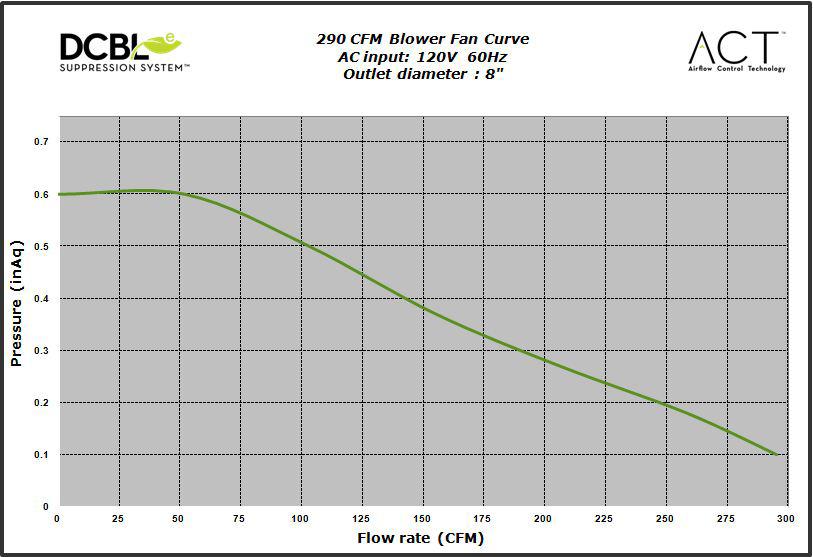
21 19 Fan Curve Diagrams
22 Wiring Diagram Model: ZMD-M90/E42AS Voltage: 120V 60Hz Power consumption Total: Max. 4 A Lamp: Max. 3Wx4 Fan: Max. 203W THERMALLY PROTECTED V W U U V W 5A 250V AC-N AC-L ON/OFF DOWN UP LAMP ACT 590 CFM - Fan Max. 1.8A ACT 390 CFM - Fan Max. 1A ACT 290 CFM - Fan Max. 20
23 DESCRIPTION PART# Replacement Parts Light Bulb, LED 3W Z0B-0032 Aluminum Mesh Filter Optional Accessories Recirculating Kit ZRC-00MD Replacement Charcoal Filter Z0F-C002 Wireless Remote Control Kit RC-0001 To order parts, visit us online at or call us at List of Parts & Accessories 21
24 Warranty from defects in materials or workmanship as follows: Three Year Limited Warranty for Parts: For three years from the date of your original purchase of the Products, we will provide, free of charge, Products or par manufacturing defects subject to the exclusions and limitations below. We may choose, in our sole discretion, to repair or replace parts before we elect to replace the Products. One Year Limited Warranty for Labor: For one year from the date of your original purchase of the Products, we will provide, free of charge, the labor cost associated with repairing the Products or parts to replace those that failed due to manufacturing defects subject to the exclusions and limitations below. After the first year from the date of your original purchase, you are responsible for all labor costs associated with this warranty. Warranty Exclusions: This warranty covers only repair or replacement, at our option, of defective Products or parts and does not cover any other costs related to required for the Products and consumable parts such as fluorescent, incandescent or halogen light bulbs, mesh and char- e been subject to freight damage, misuse, negligence, accident, faulty installation or installation contrary to recommended inst natural wear of the finish of the Products or wear caused by improper maintenance, use of corrosive and abrasive cleaning products, pads, and oven cl dents or cracks caused by abuse or mi trips to your home to teach you how to tions or alterations that impact serviceability of the Products. If you are outside our service area, additional charges may apply for shipping costs for warranty repair at our designated service locations and for the travel cost to have a service technician come to your home to repair, remove or reinstall the Products. After the first year from the date of your original purchase, you are also responsible for all labor costs associated with this warranty. All Products must be installed by a qualified professional installer to be eligible for warranty repairs or service. Limitations of Warranty. OUR OBLIGATION TO REPAIR OR REPLACE, AT OUR OPTION, SHALL BE YOUR SOLE AND EXCLUSIVE REMEDY UNDER THIS WARRANTY. WE SHALL NOT BE LIABLE FOR INCIDENTAL, CONSEQUENTIAL OR SPECIAL DAMAGES ARISING OUT OF OR IN CONNECTION WITH THE USE OR PERFORMANCE OF THE PRODUCTS. THE EXPRESS WARRANTIES IN THE PRECEDING SECTION ARE EXCLUSIVE AND IN LIEU OF ALL OTHER EXPRESS WARRANTIES. WE HEREBY DISCLAIM AND EXCLUDE ALL OTHER EXPRESS WARRANTIES FOR THE PRODUCTS, AND DISCLAIM AND EXCLUDE ALL WARRANTIES IMPLIED BY LAW, INCLUDING THOSE OF MERCHANTABILITY AND FITNESS FOR A PARTICULAR PURPOSE. Some states or provinces do not allow limitations on the duration of an implied warranty or the exclusion or limitation of incidental or consequential damages, so the above limitations or exclusions may not apply to you. To the extent that applicable law prohibits the exclusion of implied warranties, the duration of any applicable implied warranty is limited to the same three-year and one-year periods described above if permitted by applicable law. Any oral or written description of the Products is for the sole purpose of identifying the Products and shall not be construed as an express warranty. Prior to using, implementing or permitting use of the Products, you shall determine the suitability of the Products for the intended use, and you shall assume all risk and liability whatsoever in connection with such determination. We reserve the right to use functionally equivalent refurbished or reconditioned parts or Products as warranty replacements or as part of warranty service. This warranty is not transferable from the original purchaser and only applies to the consumer residence where the Product was originally installed located in the United States and Canada. This warranty is not extended to resellers. To Obtain Service Under Limited Warranty: telephone number stated below within 60 days of the discovery At the time of the request for warranty service, you must present evidence of your proof of purchase and proof of the original purchase date. If we determine that the warranty exclusions listed above apply or if you fail to provide the necessary documentation to obtain service, you will be responsible for all shipping, travel, labor and other costs related to the services. This warranty is not extended or restarted upon warranty repair or replacements. Please check our website for any additional Product information,. Zephyr Ventilation Service Department, 2277 Harbor Bay Parkway, Alameda, CA
25 23
26 PRODUCT REGISTRATION Congratulations on your Zephyr range hood purchase! Please take a moment to register your new range hood at /registration IT S IMPORTANT Prompt registration helps in more ways than one. Ensures warranty coverage should you need service. Ownership verification for insurance purposes. Notification of product changes or recalls. Zephyr Ventilation 2277 Harbor Bay Pkwy. Alameda, CA
27 Guide d utilisation, d entretien et d installation Modena Island ZMD-M90AS ZMD-E42AS Numéro de modèle : Numéro de série : NOV Zephyr Ventilation LLC. Pour une utilisation avec des modèles de numéros de série commençant par 24 + C Airflow Control Technology TM
28
29 MISE EN GARDE DE SÉCURITÉ LISTE DU MATÉRIEL... 4 INSTALLATION COMMANDES Feuille de calcul pour le conduit... 5 Espace libre et hauteur de montage... 6 Options d installation pour le conduit Montage de la hotte Reprise d air sans conduit Interface utilisateur Table des matières ENTRETIEN DÉPANNAGE TABLEAU DE RENDEMENT DU VENTILATEUR SCHÉMA DE CÂBLAGE LISTES DES ACCESSOIRES ET DES PIÈCES GARANTIE ENREGISTRMENT DU PRODUIT
30 LISEZ ET CONSERVEZ CES INSTRUCTIONS Mise en garde de sécurité AVERTISSEMENT POUR RÉDUIRE LES RISQUES D INCENDIE OU DE DÉCHARGE ÉLECTRIQUE, N UTILISEZ PAS CET APPAREIL AVEC UN TABLEAU DE COMMANDE À SEMI-CONDUCTEURS. AVERTISSEMENT POUR RÉDUIRE LES RISQUES D INCENDIE, DE DÉCHARGE ÉLECTRIQUE OU DE BLESSURE, RESPECTEZ CES CONSIGNES : a. N utilisez cet appareil que de la manière prévue par le fabricant. Si vous avez des questions, communiquez avec le fabricant. b. Avant de procéder au nettoyage ou à l entretien de l appareil, éteignez l alimentation du panneau électrique et bloquez le dispositif de déconnexion pour éviter que l alimentation électrique ne soit accidentellement rallumée. Si le dispositif de sectionnement d électricité ne peut être bloqué, attachez un avertissement (comme une étiquette) bien en vue sur le tableau électrique. ATTENTION Pour ventilation générale seulement. N utilisez pas cet appareil pour évacuer des vapeurs et des matériaux explosifs ou dangereux. Prenez garde lors de l utilisation d agents nettoyants ou de détergents. Ne devrait être utilisé que dans la cuisine de votre maison. AVERTISSEMENT POUR RÉDUIRE LES RISQUES DE FEU DE GRAISSE SUR LA SURFACE DE CUISSON : a. Ne laissez jamais l appareil sans surveillance lors de son utilisation à haute température. Les débordements par bouillonnement causent de la fumée et des déversements de graisse qui peuvent prendre feu. Faites chauffer l huile à des températures basses ou moyennes. d. Utilisez des poêlons aux dimensions adéquates. Utilisez toujours une batterie de cuisine correspondant aux dimensions de l élément. f. Utilisez le réglage haut de la hotte seulement lorsque nécessaire. g. Ne laissez pas la hotte sans surveillance lorsque vous cuisinez. h. Utilisez toujours une batterie de cuisine et des ustensiles convenant au type et à la quantité de nourriture que vous préparez. AVERTISSEMENT POUR RÉDUIRE LES RISQUES DE BLESSURE LORS D UN INCENDIE SUR LA SURFACE DE CUISSON : a. ÉTOUFFEZ LES FLAMMES avec un couvercle, une plaque à biscuits ou un plateau de métal et éteignez ensuite le brûleur. PRENEZ GARDE b. NE PRENEZ JAMAIS UN POÊLON EN FEU Vous pourriez vous brûler. c. N UTILISEZ PAS D EAU, ou un linge à vaisselle mouillé une violente explosion de vapeur s ensuivra. d. Utilisez un extincteur SEULEMENT si : 1. Vous savez que vous possédez un extincteur de classe ABC et vous savez vous en servir. 2. Le feu est faible et ne s est pas répandu depuis son point d origine. 3. Vous avez appelé le service d incendie. AVERTISSEMENT POUR RÉDUIRE LES RISQUES D INCENDIE, DE DÉCHARGE ÉLECTRIQUE OU DE BLESSURE, SUIVEZ LES CONSIGNES SUIVANTES : standards en vigueur, dont les normes des constructions ayant une cote de résistance au feu. b. Pour prévenir les contre-explosions, une certaine quantité d air est nécessaire pour la combustion et l évacuation des gaz par le carneau (cheminée) de l appareil de combustion. Respectez les directives du fabricant d outillage de chauffage et les normes de sécurité comme celles publiées par la NFPA (Association nationale des services d incendie), par la Société américaine des ingénieurs en chauffage, réfrigération et climatisation (ASHRAE) et par les normes des autorités locales. c. Lorsque vous coupez ou percez un mur ou un plafond, assurez-vous de ne pas endommager le câblage électrique ou toute autre installation technique dissimulée. d. Les ventilateurs canalisés doivent toujours évacuer l air à l extérieur. e. Si l appareil est installé près d une baignoire ou d une douche, il doit être désigné convenablement pour cette application et être branché à un disjoncteur de fuite de terre. f. N installez JAMAIS un interrupteur à une distance atteignable depuis un bain ou une douche. g. Assurez-vous que l alimentation électrique est éteinte avant de procéder à l installation, au câblage ou à l entretien de l appareil 2
31 ATTENTION POUR RÉDUIRE LES RISQUES D INCENDIE, N UTILISEZ QUE DES CONDUITS D AÉRATION EN MÉTAL. CET APPAREIL N EST PAS CONÇU POUR ÊTRE UTILISÉ À L EXTÉRIEUR. ATTENTION Pour réduire les risques d incendie et pour évacuer l air convenablement, assurez-vous de canaliser l air à l extérieur de la maison. N installez pas l échappement du conduit dans les espaces entre les murs, le plafond, le grenier, les vides sanitaires ou le garage. FONCTIONNEMENT accrocher des cheveux, des doigts ou des vêtements amples. Le fabricant se dégage de toute responsabilité dans les cas de non-respect des instructions transmises dans le présent manuel pour l installation, l entretien et l utilisation adéquate du produit. Le fabricant se dégage également de toute automatiquement lors de l entretien inapproprié de l appareil. *NOTE : Veuillez communiquer avec nous ou visitez le pour obtenir des révisions avant de procéder à des travaux sur commande. EXIGENCES ÉLECTRIQUES Important : Respectez tous les codes et règlements en vigueur. Il est de la responsabilité du client de : - S assurer que l installation électrique est adéquate et qu elle respecte le Code national de l électricité, la plus récente édition* du ANSI/NFPA 70 ou des normes du CSA C , le Code canadien de l électricité, section 1, la plus récente édition** du code C22.2 No.0-M91 ainsi que tous les codes et réglements en vigueur. N effectuez pas la mise à la terre à un tuyau de gaz. N introduisez aucun fusible dans le circuit neutre ou de mise à la terre. *National Fire Protection Association Batterymarch Park, Quincy, Massachusetts ** CSA International 8501 East Pleasant Valley Road, Cleveland, Ohio Cet appareil requiert une alimentation électrique de 120V 60Hz. Il doit être connecté à un circuit terminal individuel dûment mis à la terre, protégé par un disjoncteur de circuit ou un fusible temporisé de 15 ou 20 ampères. Le câblage doit Un raccord de câble (non inclus) pourrait également être exigé par les normes et réglementations locales. Informez-vous des exigences et des normes locales. Achetez et installez le connecteur approprié si nécessaire. ZMD-M90AS MAX 215 Watts, 4 Ampères ZMD-E42AS MAX 215 Watts, 4 Ampères Mise en garde de sécurité pour plus d informations. 3
32 Zone de découpage ombragée Devant de la hotte L C / Liste du matériel MODÈLES : ZMD-M90AS, ZMD-E42AS PIÈCES FOURNIES 2 - Pièces de recouvrement supérieures pour le conduit 2 - Pièces de recouvrement inférieures pour le conduit A 1 - Cadre de fixation supérieur B 1 - Gabarit de plafond en papier 1 - Support de cadre de fixation 1 - Cadre de fixation inférieur 1 - Registre circulaire de 8 (préinstallé 1 - Boîtier de la hotte avec ventilateur (préinstallé) 2 - Support de fixation 4 - Ampoules DEL 3W 1 - Trousse de quincaillerie 1 - Filtres à tamis en aluminium CONTENU DE LA TROUSSE DE QUINCAILLERIE (3) Capuchons de connexion (4) M6 x 1-1/2 (vis à bois) (4) rondelles ø12 OD / ø5 ID (1) M4 x 12 (vis de sûreté) (4) 3/16 x 3/8 (20) M4 x 8 PIÈCES NON FOURNIES - Conduit et tous les outils d installation - Raccord de câble (si exigé par les codes en vigueur) - Accessoire prolongement pour recouvrement de conduit - Accessoire reprise d air 4
33 Pièces de conduit = Tot a l 3-1/ 4 x 10 1 pi x ( ) = pi 6 circ. à 5 pi x ( ) = pi rect., droit rect. de 3-1/4" x 10" 6, 7, 8, 10 1 pi x ( ) = pi circ., droit 3-1/ 4 x pi x ( ) = pi rect., coude à 90º 3-1/ 4 x 10 9 pi x ( ) = pi rect., coude à 45º 3-1/ 4 x pi x ( ) = pi rect., coude plat à 90º 7 to 6 or 8 to 7 circ. reducteur conique 6, 7, 8 circ. bouchone de l air Longueur x Nombre utilisé 25 pi x ( ) = pi 15 pi x ( ) = pi 6, 7, 8, pi x ( ) = pi circ., coude à 90º 6, 7, 8, 10 9 pi x ( ) = pi coude à 45º Sous-total - colonne 1= Longueur maximale du conduit d aération : Pour un mouvement d air convenable, la longueur totale d un conduit d aération ne devrait pas compter plus que l équivalent de 100 pieds. pi Pièces de conduit 6 circ. à rect. de 3-1/4" x 10", coude à 90º 6 circ. à rect. de 3-1/4" x 10" 6 circ. à rect. de 3-1/4" x 10", coude à 90º 7 circ. à rect. de 3-1/4" x 10" 7 circ. à rect. de 3-1/4" x 10", coude à 90º 3-1/ 4 x 10 embout mural rect./registre Longueur x Nombre utilisé Tot a l 20 pi x ( ) = pi 1 pi x ( ) = pi 16 pi x ( ) = pi 8 pi x ( ) = pi 23 pi x ( ) = pi 30 pi x ( ) = pi 6, 7, 8, pi x ( ) = pi embout mural circ./registre 6, 7, 8, pi x ( ) = pi chapeau de toiture circ. = Sous-total - colonne 2 = Sous-total - colonne 1 = Total du conduit = pi pi pi Installation Feuille de calcul pour le conduit d aération 5
34 Installation Espace libre et hauteur de montage min. D min. E max. F Hauteur de la hotte CONDUIT D AÉRATION Un conduit circulaire de 8 doit être utilisé pour assurer une circulation d air maximale. N utilisez que des conduits en métal rigide. Les conduits souples pourraient réduire la circulation d air jusqu à 50 %. Utilisez la feuille de calcul pour obtenir la longueur totale du conduit (page 5). Lorsqu il est possible de le faire, diminuez TOUJOURS le nombre de pièces et de changements de direction. Si un long tronçon de conduit est nécessaire, augmentez le diamètre du conduit de 8 à Recouvrement de conduit standard 26 min. 34 max. minimum avec conduit (A) minimum avec reprise d air (B) maximum (C) min. A min. B max. C Prolongement de recouvrement de conduit Hauteur de plafond minimum avec conduit (D) 90 (7 6 ) 105 (8 9 ) minimum avec reprise d air (E) 94 (7 10 ) 108 (9 ) maximum (F) 120 (10 ) 150 (12 6 ) La hauteur de montage minimale ne devrait pas être moins de 26. La hauteur de montage maximale ne devrait pas outrepasser 34. Il est important d installer la hotte à la hauteur de montage adéquate. Les hottes installées trop basses pourraient être endommagées par la chaleur en plus de présenter des risques d incendie plus élevés tandis que les hottes installées trop Si elles sont disponibles, consultez les exigences de hauteur d espace libre requise par le fabricant de la cuisinière ainsi que la hauteur recommandée de montage de la hotte au-dessus de la surface de cuisson. Informez-vous toujours des normes et des réglementations locales en vigueur pour toute différence par rapport aux normes du fabricant. Ensemble de recouvrement de conduit disponible pour les plafonds atteignant 12 pieds. Numéro de pièce et information pour commander disponibles à la page 21. ENDOMMAGEMENT LORS DE LA LIVRAISON/ INSTALLATION : de l appareil ne sont pas endommagées avant l installation. acheté pour réparation ou remplacement. réparation ou le remplacement est à la charge du client. (si autre que le client), le client et l installateur doivent en venir à une entente pour la réparation ou le remplacement. Si des changements de direction ou des adaptateurs sont nécessaires, installez-les le plus loin possible de l ouverture et le plus éloigné possible l un de l autre. 6
35 AVERTISSEMENT DE RISQUE D INCENDIE N évacuez ou ne terminez JAMAIS l échappement du conduit dans les espaces entre les murs, les vides sanitaires, le plafond, le grenier, ou le garage. Tous les échappements doivent être dirigés à l extérieur de la maison, à moins que l option de reprise d air ne soit utilisée. N utilisez que des conduits en métal pour cloison simple. Fixez toutes les pièces du conduit avec des vis à tôle et isolez tous les joints avec du ruban adhésif en toile ou du (Boîtier de ventilateur) Pente de la toiture avec solin et chapeau (Boîtier de ventilateur) Retombée de plafond ou vide sanitaire Bouche d aération de mur latéral avec clapet antirefoulement Installation Options pour le conduit d aération (Boîtier de ventilateur) Reprise d air sans conduit 7
36 Installation 1 1/4 4 1/ / / /16, 41 15/16 DEVANT L/C Entrée CA 9 11/ /8 L/C 7 3/4 1 3/ / /2 CÔTÉ 11 3/8 11 5/8 5 7/8 L/C STANDARD Min. avec conduit - 28 Min. avec reprise d air - 32 Max Z1C-00MD Min. avec conduit - 43 Min. avec reprise d air - 46 Max /16 1 7/8 DESSUS de la HOTTE 1/2 5 1/4 CADRE DE FIXATION SUPÉRIEUR (vue du dessus) 8

37 ! AVERTISSEMENT : Le câblage électrique doit être effectué par une ou des personnes qualifiées selon les stipulations de tous les normes et standards en vigueur. Éteignez l alimentation électrique à l entrée de service avant de procéder au câblage. Solives de plafond Bloc de bois Cadre de fixation supérieur Cadre de fixation inférieur Boîtier/pavillon de la hotte front GABARIT EN PAPIER Devant de la hotte Installation 1. Déterminez l emplacement pour l installation de la hotte et collez temporairement le gabarit en papier (inclus avec la hotte) au plafond. Dans le plafond, faites un trou correspondant à la zone interne ombragée du gabarit. C est là que passeront le conduit et les câbles électriques. Ajoutez les blocs de bois (min. 2 x 4 ) aux solives de plafond, sur la cloison sèche, pour renforcer le plafond (FIG. A#1). Fixez deux vis à bois 1-1/2 aux points A et B du gabarit en papier (FIG. B). Ne serrez pas les vis jusqu au bout et laissez dépasser environ 1/
38 Installation FRONT FRONT pouces. Fixez les pattes de support latérales à l aide de douze vis à tôle M4 x 8. (FIG. C) 50 pouces. Fixez les pattes de support carrées aux bras du cadre hauteur moindre (FIG. E, no 2). solidement au plafond. Serrez les vis. 10
39 ! ATTENTION : Compte tenu du poids et des dimensions de la hotte, au moins deux installateurs sont nécessaires. SUPPORT DE MONTAGE DU DISPOSITIF ÉLECTRONIQUE Installation 7. Enlevez le ruban qui retient le support de montage du dispositif électronique à la hotte (FIG. F#1). Enlevez les trois vis du dessus du boîtier de la hotte et laissez-les de côté. Placez le support de montage du dispositif préalablement enlevées. 8. Soulevez le boîtier de la hotte et alignez les quatre vis de montage préinstallées sur le dessus du boîtier du 9. Installez l électricité et le conduit d aération. Scellez le conduit avec du ruban à conduit en aluminium. des fuites d air autour du ruban à conduit. 11
40 Installation Top Support Frame Top Duct Covers Bottom Duct Covers 1 Bottom Support Frame cadre du support supérieur à l aide des bandes magnétiques. Note : Si vous utilisez la hotte en mode de reprise d air, de recouvrement de conduit. Consultez la page 13 pour plus de détails. J1). ensemble à l aide des bandes magnétiques. 12
41 un conduit d aération. Lorsque transformée, la hotte fonctionne comme une hotte de reprise d air plutôt que Nous recommandons de TOUJOURS évacuer l air à l extérieur de la maison en utilisant le conduit en place ou, d installer un conduit d aération. ENSEMBLE DE REPRISE D AIR (REQUIS SI AUCUN CONDUIT N EST UTILISÉ ZMD-M90AS ZRC-00MD 1 ZMD-E42AS ZRC-00MD 1 1. Procurez-vous l ensemble de reprise d air en utilisant le numéro de pièce ci-dessus de conduit (FIG. K). Installez le conduit de 8 à la partie supérieure sont préinstallées dans la hotte et doivent d abord être enlevées. K). panneau indicateur (consultez la page 15 pour plus de détails). Le microprocesseur des commandes vous indiquera le moment consultant la liste ci-dessous. Note : Consultez le manuel compris avec l ensemble de reprise d air pour obtenir des instructions d installation plus détaillées ZMD-M90AS Z0F-C002 1 ZMD-E42AS Z0F-C002 1 Installation Reprise d air sans conduit NE NETTOYEZ PAS LES FILTRES À CHARBON. Vous pourriez avoir à 13
42 Commandes - Touche de mise en marche/arrêt automatique Affichage (vitesse, arrêt automatique, nettoyage/changement des filtres, purification d air) clean mesh filter clean air replace charcoal filter Choix de six vitesses Lumières : Allumer/Veilleuse/Éteindre 1-Touche de mise en marche/arrêt automatique Fonction de mise en marche - La touche permet d allumer et d éteindre la hotte (ventilateur et lumières). - Lorsqu elle est éteinte, la hotte garde en mémoire la dernière vitesse et le dernier niveau d éclairage (Exemple : Vous appuyez sur la touche lorsque le ventilateur est à la vitesse 4 et que les lumières sont à haute intensité. Si vous appuyez de nouveau sur la touche pour allumer la hotte, le ventilateur se remet en marche à la vitesse 4 et les lumières s allument à haute intensité). Fonction d arrêt automatique - Appuyez sur le bouton et tenez-le enfoncé pendant deux secondes pour que le ventilateur s allume à la vitesse 1. Le symbole s illumine. Après cinq minutes, le ventilateur et les lumières s éteignent automatiquement. - Si vous appuyez sur le bouton lorsque la fonction d arrêt automatique est activée, la hotte s éteint et annule la fonction d arrêt automatique. Débit d'air contrôle de la technologie (ACT) - ACT permet à l'utilisateur de contrôler le maximum CFM de la ventilateur. - Pour vérifier le CFM du vos ventilateur: - Avec la hotte désactivé, maintenez le bouton pendant trois secondes. Le CFM de la ventilateur sera affiché sur l'écran LCD. 2-Touche de choix de vitesse Touche de réduction de la vitesse du ventilateur - Appuyez sur ce bouton pour réduire la vitesse du ventilateur. 6 (Rafale), 5, 4, 3, 2, 1. - Si le ventilateur est à la vitesse 1 lorsque vous appuyez sur cette touche, il s éteint. Touche d augmentation de la vitesse du ventilateur - Appuyez sur ce bouton pour augmenter la vitesse du ventilateur. 1, 2, 3, 4, 5, 6 (Rafale). - Si la hotte est éteinte lorsque vous appuyez sur cette touche, le ventilateur s allume à la vitesse 1. Mode Rafale - Cette vitesse est conçue pour changer l air intensément et rapidement lorsqu une grande quantité de fumée est générée. Après trois minutes, le ventilateur passe automatiquement à la vitesse 5. 3-Touche des lumières - Il y a deux intensités pour les lumières : haute et basse. - Lorsqu elles sont éteintes, appuyez une fois pour allumer les lumières à haute intensité. Les mots «lights hi» apparaissent pendant deux secondes à l écran LCD. - Appuyez de nouveau pour les mettre à basse intensité. Les mots «lights lo» apparaissent pendant deux secondes sur l écran LCD. - Appuyez encore une fois pour éteindre les lumières. 14
43 Indicateur de nettoyage des filtres à tamis (toujours en fonction) - Après 30 heures d utilisation du ventilateur, le symbole et les mots «clean mesh filter» s illuminent, indiquant qu il est temps de nettoyer les filtres à tamis. Le symbole et les mots restent illuminés jusqu à la réinitialisation de la fonction. - Pour réinitialiser : Lorsque la hotte est éteinte, appuyez et tenez la touche enfoncée pendant trois secondes. Après trois secondes, le symbole et les mots «clean mesh filter» s éteignent et le temporisateur de 30 heures est réinitialisé. Indicateur de remplacement du filtre à charbon (désactivé par défaut, doit être activé avec le mode de reprise d air) - Pour activer la fonction de remplacement du filtre à charbon : - Lorsque la hotte est éteinte, appuyez et tenez simultanément les touches et pendant trois secondes. Le symbole s illumine pendant trois secondes, indiquant que la fonction de remplacement des filtres est activée. - Pour désactiver la fonction de remplacement du filtre à charbon : - Lorsque la hotte est éteinte, appuyez et tenez simultanément les touches et pendant trois secondes. Le symbole s illumine pendant trois secondes puis s éteint, indiquant que la fonction de remplacement des filtres est désactivée. - Après 120 heures d utilisation du ventilateur, le symbole et les mots «replace charcoal filter» s illuminent, indiquant qu il est temps de remplacer les filtres à charbon. Le symbole et les mots resteront illuminés jusqu à la réinitialisation de la fonction. - Pour réinitialiser : Lorsque la hotte est éteinte, appuyez et tenez la touche enfoncée pendant trois secondes. Après trois secondes, le symbole et les mots «replace charcoal filter» s éteignent et le temporisateur de 120 heures est réinitialisé. Indicateur de purification d air - La fonction de purification d air allume le ventilateur pour une période de dix minutes toutes les quatre heures pour enlever l air stagnant qui flotte dans la cuisine. - Pour activer la fonction de purification d air : - Lorsque la hotte est éteinte, appuyez et tenez simultanément les touches et pendant trois secondes. Le symbole et les mots «clean air» s illuminent et le ventilateur se met en marche à la vitesse 1 pendant dix minutes. Après dix minutes, le ventilateur s éteint et le temporisateur de quatre heures est réinitialisé. - Le symbole reste illuminé lorsque la fonction de purification d air est activée, même si le ventilateur n est pas allumé. - Pour désactiver la fonction de purification d air : - Lorsque la hotte est éteinte, appuyez et tenez simultanément les touches et pendant trois secondes jusqu à ce que le symbole s éteigne. - Lorsque la fonction de purification d air est activée, le ventilateur fonctionne à la vitesse 1 pendant dix minutes toutes les quatre heures, lorsque le ventilateur n est pas utilisé. Après dix minutes, le ventilateur s éteint et le temporisateur de quatre heures est réinitialisé. - Si l utilisateur change la vitesse du ventilateur lorsque la fonction de purification d air est en cours de marche, les mots «clean air» s éteignent, mais le symbole reste illuminé. Si l utilisateur appuie sur la touche, la période de quatre heures est réinitialisée. Commandes 15
44 Entretien - ENTRETIEN DES SURFACES: Nettoyez régulièrement les surfaces de la hotte avec de l eau savonneuse chaude et un chiffon de coton propre. N utilisez pas de détergent abrasif ou corrosif, de laines d acier ou de tampons à récurer; ils égratigneront et endommageront les surfaces. Pour les taches plus tenaces, utilisez du produit dégraissant liquide. Après le nettoyage, vous pouvez polir les surfaces avec des produits de polissage à acier inoxydable non abrasifs pour redonner de l éclat et du lustre aux surfaces. Frottez toujours doucement, avec un chiffon de coton propre, et dans le sens du grain. de cuisson. Ils ne nécessitent aucun remplacement sur une base régulière, mais doivent être gardés propres. culinaires. Enlevez-les et nettoyez-les à la main ou au lave-vaisselle avec de l eau tiède. Vaporisez avec du détergent pour graisse et laissez tremper pour éliminer la saleté accumulée. hotte. 1. Poussez sur les poignées à ressort 16
45 PROCÉDURES DE DÉPANNAGE POUR LA HOTTE MODENA ISLAND Problème Cause Solution Après l installation, l appareil ne fonctionne pas. Les lumières fonctionnent, mais le moteur ne tourne pas. 1. Le bloc d alimentation n est pas allumé 1. Assurez-vous que l alimentation du disjoncteur et de l appareil est allumée 2. La ligne électrique et le raccord de câble ne sont pas correctement branchés commande sont débranchés fait correctement tableaux de contrôle et de commande sont branchés convenablement 4. Tableau de contrôle/commande défectueux 4. Remplacez le tableau de contrôle/commande 1. Le moteur est défectueux, possiblement bloqué 1. Remplacez le moteur 2. Le système de protection thermale détecte que le moteur est trop chaud pour fonctionner et l éteint. 2. Le moteur fonctionnera normalement lorsque le système de protection thermale aura refroidi 3. Tableau de contrôle/commande défectueux 3. Remplacez la pièce défectueuse L appareil vibre. 1. Fixez solidement le moteur en place 2. La roue du ventilateur est endommagée 2. Remplacez le ventilateur 4. Tableau de contrôle/commande défectueux 4. Remplacez la pièce défectueuse Les niveaux de vitesse de même son. Le moteur fonctionne, mais pas les lumières. La hotte ne fonctionne pas bien. vibre. 1. Utilisation de la mauvaise taille de canalisation. 1. Changer le conduit à au moins 8 ou plus. 2. Le niveau de bruit distinction entre certains des vitesses peut être minime quand ACT permis ventilateur est réglé à 290 ou 390 CFM. 1. L ampoule DEL est défectueuse 1. Remplacez l ampoule DEL 1. La hotte est possiblement installée trop haut par rapport à la cuisinière 2. Du vent provenant d une fenêtre ou d une porte ouverte avoisinante nuit à la ventilation 3. L ouverture du conduit ou le conduit lui-même est bloqué 1. Ajustez la distance entre la surface de la cuisinière et la base de la hotte entre 26 et Fermez toutes les portes et fenêtres pour éliminer les courants d air 3. Enlevez tout ce qui bloque l ouverture ou le conduit d aération 4. L ouverture du conduit est contre le vent 4. Ajustez l orientation de l ouverture du conduit 5. Mauvaises dimensions de conduit d aération 5. Remplacez le conduit par un conduit adéquat de 6 de diamètre ou plus pour le ventilateur interne 1. Assurez-vous que les attaches métalliques de la poignée ne sont pas bloquées. Ou Dépannage 17


46 Tableau De Rendement Du Ventilateur Débit d air contrôle de la technologie (ACT) Certains codes locaux de limiter le montant maximum de CFM qu une hotte de cuisinière peut se déplacer. ACT vous permet de contrôler le maximum CFM de les hottes avec le système de répression DCBL à partir de Zephyr sans avoir besoin de coûteux kits pour l air de remplacement. ACT permet à l installateur de régler facilement la vitesse maximale du ventilateur à l un des trois les plus couramment prescrits niveaux de CFM; 590, 390 ou 290 CFM. L utilisation de l ACT peut-être pas nécessaire pour votre installation. S il vous plaît vérifiez vos codes locaux pour connaître les restrictions des CFM. Par défaut, le CFM maximale du le ventilateur est réglé à 715. Pour vérifier si votre installateur a permis ACT; Avec le hotte désactivé, appuyez et maintenez le bouton d alimentation pendant trois secondes. Le CFM du le ventilateur sera affiché sur l écran LCD. Il y a devrait également être une étiquette feuille d aluminium situé à l intérieur du corps de la hotte à proximité de la schéma de câblage qui indique le CFM du le ventilateur. 18
 Tableau De Rendement Du Ventilateur")
47 Pression (en TQ) Courbe de rendement du ventilateur, 390 CFM Entree en CA: 120V, 60 Hz Diametre du conduit de sortie : 8 Debit (pi3/min) Tableau De Rendement Du Ventilateur 19
Use, Care, and Installation Guide
 www.zephyronline.com Use, Care, and Installation Guide Napoli ZNA-M90CS ZNA-E42CS Model number: Serial Number: SEP14.0101 Zephyr Ventilation LLC. + C Airflow Control Technology TM www.zephyronline.com
Use, Care, and Installation Guide
 Use, Care, and Installation Guide Titan AK7636AS AK7642AS AK7648AS AK7654AS AK7660AS Model number: Serial Number: NOV18.0301 Zephyr Ventilation LLC. READ AND SAVE THESE INSTRUCTIONS SAFETY NOTICE... 2-3
1. Configurez votre Stick Up Cam Wired dans l application Ring.
 Stick Up Cam Wired 1. Configurez votre Stick Up Cam Wired dans l application Ring. Téléchargez l application Ring. L application vous guide dans la configuration et l utilisation de votre Stick Up Cam
Use, Care, and Installation Guide
 www.zephyronline.com Use, Care, and Installation Guide Breeze I AK1124x, AK1100x, AK1136x Breeze II AK1200x, AK1236x Model number: Serial Number: Date of Purchase: Sales Dealer: MAY13.0501 Zephyr Corporation
Installation Instructions
 Installation Instructions Island Vent Hood ZV850, ZV855 Hotte Aspirante Îlot Instructions d installation La section française commence à la page 22 Campana de ventilación en isla Instrucciones de instalación
Installation Instructions
 Installation Instructions 36 Vent Hood ZV750, ZV755 Hotte Aspirante 36 po Instructions d installation La section française commence à la page 19 Campana de ventilación de 36 Instrucciones de instalación
HOLA SAFETY RING PLAN
 FRENCH VERSION ON PAGE 3 HOLA SAFETY RING PLAN PRICE: $50.00 per person EFFECTIVE FEBRUARY 01, 2019 The Hola Safety Ring Plan allows you to cancel your trip with a refund up to 3 days before departure
GUIDE D INSTALLATION PVC CELLULAIRE
 GUIDE D INSTALLATION PVC CELLULAIRE 7 5 3 4 1 2 6 8 NOTES IMPORTANTES Travailler toujours de gauche à droite, de bas en haut. Utiliser des vis en acier inoxidable #8 x 1.5 (3,8 cm) à tous les 16 /40,64
Installation Instructions
 Installation Instructions 30 Chimney Vent Hood For Model: ZV830 30 (76,2 cm) Hotte aspirante Instructions d installation Pour la Modèle : ZV830 La section française commence à la page 21 Campana de ventilación
Roll Up 28. Ref A. DE Anleitung FR Notice ES Manual PT Instruções PL Instrukcja RU Руководство CS Návod
 Roll Up 28 WT Ref. 5122117A DE Anleitung FR Notice ES Manual PT Instruções PL Instrukcja RU Руководство CS Návod Copyright 2013 Somfy SAS. All rights reserved - V1-02/2013 1 Sommaire 1. Informations préalables
I We reserve the right to modify or attar Instructions. No modification or
 INSTALLATION INSTRUCTION VLFS3265 Floor Stand TV Mobile Cart For TV panels: 32"-65" Maximum load capacity: 100 lbs/ 45.5 kg AV shelf max load: 10 lbs/ 4.5 kg Video tray max load: 10 lbs/ 4.5 kg VESA: 100x100-600x400mm
Fire's Edge Fire Pit/Fire Pit Inserts For (Automated) Model 100-A
 Model 100-A") Fire's Edge Fire Pit/Fire Pit Inserts For (Automated) Model 100-A OWNER S MANUAL / OPERATING AND MAINTENANCE INSTRUCTIONS For your safety: If you smell gas: 1. Shut off gas to the appliance 2. Extinguish
Fire's Edge Fire Pit/Fire Pit Inserts For (Automated) Model 100-A OWNER S MANUAL / OPERATING AND MAINTENANCE INSTRUCTIONS For your safety: If you smell gas: 1. Shut off gas to the appliance 2. Extinguish
WC35 Series. In USA - BEST Hartford, Wisconsin In CANADA - BEST Drummondville, QC, Canada ENGLISH...2 FRANÇAIS...24 ESPAÑOL... 47
 WC35 Series ENGLISH...2 FRANÇAIS...24 ESPAÑOL... 47 In USA - BEST Hartford, Wisconsin In CANADA - BEST Drummondville, QC, Canada REGISTER YOUR PRODUCT ONLINE AT : www.bestrangehoods.com/register For additional
Installation Instructions
 Installation Instructions Custom Hood Inserts Hotte Encastrable sur Mesure Instructions d installation La section française commence à la page 23 Encastres de campana a medida Instrucciones de instalación
Index. TerraPorte 7600 & accessable
 TerraPorte 7600 & accessable Out-Swing / Ouverture Extérieure Thermally broken frame with superior air / water performance. Rain screen design and multi-point locking ideal for residential and condominium
Cast Iron Cookware Ustensiles de cuisson en fonte Utensilios de cocina de hierro fundido INSTRUCTIONS INSTRUCTIONS INSTRUCCIONES
 Cast Iron Cookware Ustensiles de cuisson en fonte Utensilios de cocina de hierro fundido INSTRUCTIONS INSTRUCTIONS INSTRUCCIONES WELCOME TO THE WORLD OF KITCHENAID. We re committed to helping you create
ThermaWall XTRM2600 Unitized Curtain Wall
 ThermaWall XTRM2600 Unitized Curtain Wall Unitized thermally broken curtain wall - Capped and SSG, 2 1/2" (63.5mm) and 3" (76.2mm) profile widths, various system depths. Mur-rideau à bris thermique unitisé
TWO BURNER STAINLESS STEEL PROPANE STOVE
 ROTATE TO LIGHT 842-A250-0_SSCmpStove.qxd 11/26/03 2:59 PM Page 1 OWNER S MANUAL FAILURE TO FOLLOW ALL S AND INSTRUCTIONS IN THIS MANUAL COULD LEAD TO PERSONAL INJURY, INCLUDING DEATH. RETAIN THIS MANUAL
Safety instructions and warnings Package contents and parts Tool requirements Product features... 5
 Door Awning : PA Series Owner s Manual For safety reasons, please carefully read and understand all written instructions and warnings in this manual prior to assembling or installing this product. Table
, & Series Nested Hardware
 RECORD THIS INFORMATION FOR FUTURE REFERENCE BEFORE INSTALLING THE UNIT: Model Number Serial Number Date Purchased Place of Purchase USA SERVICE OFFICE Dometic Corp. 509 So. Poplar St. LaGrange, IN 46761
MARQUE: PROLINE REFERENCE: CHP60SS CODIC:
 MARQUE: PROLINE REFERENCE: CHP60SS CODIC: 4139151 NOTICE CHP60SS CHP90SS Hotte décorative Range hood Afzuigkap MANUEL D UTILISATION OPERATING INSTRUCTIONS HANDLEIDING MISES EN GARDE IMPORTANTES Cet appareil
85 Heart Lake Road South Brampton, Ontario, Canada L6W 3K2 Phone: Fax:
 Big Joe by Blue Giant Warranty AC Power Drive Straddle Trucks (PDS) AC Power Pallet Trucks (WPT45, D40) AC Power Rider Trucks (WRT-60) AC Power Counterbalanced Truck (CB-22) AC Power Task Support Vehicle
TANK MONITOR MODEL # (12V DC) (24V DC) (32V DC) OPERATION AND INSTALLATION INSTRUCTIONS
 (24V DC) (32V DC) OPERATION AND INSTALLATION INSTRUCTIONS") TANK MONITOR MODEL # 1510012 (12V DC) - 1510024 (24V DC) - 1510032 (32V DC) OPERATION AND INSTALLATION INSTRUCTIONS WARNING: Raritan Engineering Company,Inc.recommends that a qualified person install this
TANK MONITOR MODEL # 1510012 (12V DC) - 1510024 (24V DC) - 1510032 (32V DC) OPERATION AND INSTALLATION INSTRUCTIONS WARNING: Raritan Engineering Company,Inc.recommends that a qualified person install this
Models IC35I90B & IC35I90W
 Models IC35I90B & IC35I90W ENGLISH... 2 FRANÇAIS...25 ESPAÑOL... 49 In USA - BEST Hartford, Wisconsin In CANADA - BEST Drummondville, QC, Canada REGISTER YOUR PRODUCT ONLINE AT : www.bestrangehoods.com/register
SMART BIO-ETHANOL ELECTRONIC BURNER
 SMART BIO-ETHANOL ELECTRONIC BURNER User s Manual What s in the box: Smart Burner Remote Control AC Adapter Filling Hose User s Manual 1pc 1pc 1pc 1pc 1pc Preparations Remove all packaging materials prior
Index. TerraPorte 7600 & accessable
 TerraPorte 7600 & accessable Out-Swing / Ouverture Extérieure Thermally broken frame with superior air / water performance. Rain screen design and multi-point locking ideal for residential and condominium
INDOOR COOKING. Radiant Cooktop. Installation Manual
 INDOOR COOKING Radiant Cooktop KEC Installation Manual IF THE INFORMATION IN THIS MANUAL IS NOT FOLLOWED EXACTLY, A FIRE OR EXPLOSION MAY RESULT CAUSING PROPERTY DAMAGE, PERSONAL INJURY, OR DEATH. Do not
TC42 CHALET II BURNER KIT INSTALLATION INSTRUCTIONS
 INSTALLER: Leave this manual with the appliance. CONSUMER: Retain this manual for future reference. These instructions are supplementary to the Installation and Operating Instructions supplied with the
Installation Instructions Part # 2784 Awning
 Please read instructions entirely before installing this product. Parts Included Qty Parts Included Qty 1 Flat Washer (U-Bolt) 4 L Bracket 2 Nylock Nut ( U-Bolt) 4 Stake with Cord 2 6mm x 1 Bolt/Nut 10
Safety instructions and warnings Package contents and parts Tool requirements Product features... 4
 Door Awning : PN Series Owner s Manual For safety reasons, please carefully read and understand all written instructions and warnings in this manual prior to assembling or installing this product. Table
Viking Use/Installation Guide
 Viking Use/Installation Guide Viking Range Corporation 111 Front Street Greenwood, Mississippi 38930 USA (662) 455-1200 For more product information, call 1-888-VIKING1 (845-4641) or visit the Viking Web
Instructions for use, installation, and connection. Gas Built in Hob
 Instructions for use, installation, and connection Gas Built in Hob RB3311SGBS RB3312SGBS RB3311DGBS RB3311MGBS RB3311NGBS RB6313SGBST RB6323SGBST RB6314SGBS RB6313DGBST RB6313MGBST RB7312SGBS RB7313SGBST
IMPORTANT INSTRUCTIONS - OPERATING MANUAL
 IMPORTANT INSTRUCTIONS - OPERATING MANUAL Models: AS50, AS60, AS70, AS54 Exhaust Fan READ AND SAVE THESE INSTRUCTIONS READ CAREFULLY BEFORE ATTEMPTING TO ASSEMBLE, INSTALL, OPERATE OR MAINTAIN THE PRODUCT
PLEASE READ BEFORE USE AND SAVE THESE INSTRUCTIONS
 Sauce Flip Pan PLEASE READ BEFORE USE AND SAVE THESE INSTRUCTIONS Thank you for purchasing Cook s Companion Sauce Flip Pan. This pan is designed to be one of the most used pans in your kitchen. The Fusion
User Manual. 1000W Stackable 1.2 Cu. Ft. Commercial Microwave. Model: 180MW112T 05/2017. Please read and keep these instructions. Indoor use only.
 1000W Stackable 1.2 Cu. Ft. Commercial Microwave Model: 180MW112T 05/2017 Please read and keep these instructions. Indoor use only. IMPORTANT SAFETY INSTRUCTIONS When using electrical equipment, basic
Thermographie, pourquoi l utiliser?
 Thermographie, pourquoi l utiliser? Manny Alsaid FLIR Systems Jacques Wagner MultiPro Plus = 3,600 Thermomètre IR Thermometre IR La zone de mesure Distance au cible Ce quoi l infrarouge? Voir la réalité
Toyostove Error Code EE 2 (EE 6)
") Toyostove Error Code EE 2 (EE 6) WARNING Rural Energy Enterprises, Inc. does not accept liability for the improper use of this information. Installation, service, and maintenance of heating equipment should
Toyostove Error Code EE 2 (EE 6) WARNING Rural Energy Enterprises, Inc. does not accept liability for the improper use of this information. Installation, service, and maintenance of heating equipment should
! FOR DOMESTIC COOKING ONLY!!
 WARNING TO REDUCE THE RISK OF FIRE, ELECTRIC SHOCK, OR INJURY TO PERSONS, OBSERVE THE FOLLOWING: 1. Use this unit only in the manner intended by the manufacturer. If you have questions, contact the manufacturer
kurt versen INSTALLATION INSTRUCTIONS-L342/4/6 SURFACE MOUNTED LED SQUARE CYLINDER
 INSTALLATION INSTRUCTIONS-L342/4/6 SURFACE MOUNTED LED SQUARE CYLINDER MODEL: 1100/1500/2100 LUMEN : L342/4/6 (WIDE, MEDIUM, & NARROW DISTRIBUTION) Fig. 1 MOUNTING YOKE J-BOX (BY OTHERS) HOUSING J-BOX
TCO REFERENCE: BBTS-500MR RGE CODIC:
 TCO MARQUE: BRANDT REFERENCE: BBTS-500MR RGE CODIC: 1370910 Model: BBTS 500MBK BBTS 500MS BBTS 500MR BBTS 500MBU AVERTISSEMENT Cet appareil est destiné à un usage domestique uniquement. Toute utilisation
USER MANUAL PLEASE READ AND UNDERSTAND THIS MANUAL COMPLETELY BEFORE USE.
 Adventure Kings Roof Top Tent USER MANUAL PLEASE READ AND UNDERSTAND THIS MANUAL COMPLETELY BEFORE USE. Warning Improper installation or use of your Roof Top Tent may result in serious injury or death.
EB300. Ethanol Burner. User s Manual Installation Instructions
 EB300 Ethanol Burner User s Manual Installation Instructions EB300 Burner Burner Lid User s Manual What s in the box: 1pc 1pc 1pc Installation Instructions EB300 - User s Manual The Ignis Ethanol Burner
Cordless Electric Teakettle. Model 685
 Cordless Electric Teakettle Model 685 Important Safeguards When using electrical appliances, basic safety precautions should always be followed, including the following: 1. Read all instructions. 2. Do
Lit Table Top Firepit Bio-Ethanol Fireplace. User Manual. Model: GF301650
 Lit Table Top Firepit Bio-Ethanol Fireplace User Manual Model: GF301650 1 Moda Flame Lit Table Top Firepit Bio-Ethanol Fireplace Included in delivery (Parts List): A. Fireplace body 1pc B. Glass 1pc C.
RT2N Thermostat compact
 aractéristiques Excellente répétabilité Réglage de l'écart pour la régulation orrection de l'écart pour le contrôle et l'alarme Résistant à la surpression accidentelle Léger pplications Équipement de sécurité
Stilo Isola Island Mount Canopy Rangehood
 Stilo Isola Island Mount Canopy Rangehood Installation Instructions Use and Care Information READ AND SAVE THESE INSTRUCTIONS The Installer must leave these instructions with the homeowner. The homeowner
BUILT-IN OVEN SAFETY
 UILT-IN OVN SFTY Your safety and the safety of others are very important. We have provided many important safety messages in this manual and on your appliance. lways read and obey all safety messages.
AFC-50 Automatic French Fry Cutter Instruction Manual
 AFC-50 Automatic French Fry Cutter Instruction Manual Fry Factory Inc. 67 Watts Ave, Charlottetown, PEI, C1E 2B7, Canada Phone: 902-368-2900 Fax: 902-368-8645 Email: info@fryfactoryinc.com Website: www.fryfactoryinc.com
Read all instructions and warnings before using this fireplace. WARNING
 Frame User Manual 1 Operating Manual Thank you for purchasing this Signi Fires product. Signi Fires is very safety conscious, we have taken every care in designing, manufacturing and assembling your Signi
INTENDED FOR DOMESTIC COOKING ONLY READ AND SAVE THESE INSTRUCTIONS
 INSTALLATION INSTRUCTIONS HB00 WT2I SERIES INTENDED FOR DOMESTIC COOKING ONLY!! READ AND SAVE THESE INSTRUCTIONS INSTALLER: LEAVE THIS MANUAL WITH HOMEOWNER. HOMEOWNER: USE AND CARE INFORMATION ON PAGES
IMPORTANT INSTRUCTIONS - OPERATING MANUAL
 IMPORTANT INSTRUCTIONS - OPERATING MANUAL Models: AK917, AK927 Bulb Heat Lamp with Fan READ AND SAVE THESE INSTRUCTIONS READ CAREFULLY BEFORE ATTEMPTING TO ASSEMBLE, INSTALL, OPERATE OR MAINTAIN THE PRODUCT
1946 READ AND SAVE THESE INSTRUCTIONS!
 EasyAwn Installation, Care and Maintenance Manual EasyAwn Quality, Since 1946 EasyAwn, LLC Toll Free: 877-EasyAwn http://www.easyawn.com READ AND SAVE THESE INSTRUCTIONS! EasyAwn Quarter Round Awning Installation
CERO Instructions for use and safety
 CERO Instructions for use and safety READ CAREFULLY BEFORE USE Please store these safety warnings in a safe place for future reference. NOTICE: BUYER ASSUMES ALL RESPONSIBILITY FOR SAFETY AND USE THAT
MODEL K210A INTENDED FOR DOMESTIC USE ONLY READ AND SAVE THESE INSTRUCTIONS
 INSTALLATION INSTRUCTIONS HB0029 MODEL K210A INTENDED FOR DOMESTIC USE ONLY!! READ AND SAVE THESE INSTRUCTIONS INSTALLER: LEAVE THIS MANUAL WITH HOMEOWNER. HOMEOWNER: USE AND CARE INFORMATION ON PAGES
MODEL 412-3PC, RISING DOUGH PIZZA OVEN
 PIZZA OVEN MODEL 412-3PC, RISING DOUGH PIZZA OVEN This oven was designed expressly for baking rising dough pizzas. This counter top oven has dual position elements which are designed to cook quickly and
READ AND SAVE THESE INSTRUCTIONS! EasyAwn Spear Awning Installation
 EasyAwn Installation, Care and Maintenance Manual EasyAwn Quality, Since 1946 EasyAwn, LLC Toll Free: 877-EasyAwn http://www.easyawn.com READ AND SAVE THESE INSTRUCTIONS! EasyAwn Spear Awning Installation
PATRIOT INSTRUCTION MANUAL SL300C 12 MEAT SLICER 1/2 HP
 INSTRUCTION MANUAL SL300C 12 MEAT SLICER 1/2 HP This manual contains important information regarding your Patriot unit. Please read this manual thoroughly prior to equipment set-up, operation and maintenance.
READ AND SAVE THESE INSTRUCTIONS! EasyAwn Standard Awning Installation
 EasyAwn Installation, Care and Maintenance Manual EasyAwn Quality, Since 1946 EasyAwn, LLC Toll Free: 877-EasyAwn http://www.easyawn.com READ AND SAVE THESE INSTRUCTIONS! EasyAwn Standard Awning Installation
Operator s Manual. Medium-Duty Electric Slicers ENGLISH. Item Model Description Drive Peak HP Voltage Amps Hz Plug
 Medium-Duty Electric Slicers 40950 40951 Item Model Description Drive Peak HP Voltage Amps Hz Plug 40950 SLM250/S 10 Knife Medium-Duty Slicer 1/3 2.5 Belt 120 60 5-15P 40951 SLM300P/S 12 Knife Medium-Duty
TUCSON PATIO AWNING INSTALLATION MANUAL
 TUCSON PATIO AWNING INSTALLATION MANUAL Toll Free 877-792-1775 Fax 877-792-0031 swsuncontrolpro.com sales@swsuncontrol.com 1 INTRODUCTION...3 1.1 Symbols used in this manual... 3 1.2 Personnel requirements...
accidents which arise due to non-observance of these instructions and the safety information herein. CAUTION:
 AUTO REWIND HOSE REEL Model: 7640 CALIFORNIA PROPOSITION 65 WARNING: You can create dust when you cut, sand, drill or grind materials such as wood, paint, metal, concrete, cement, or other masonry. This
Oletto Single Handle Commercial Style Kitchen Faucet
 INSTALLATION MANUAL Oletto Single Handle Commercial Style Kitchen Faucet KPF-2631 www.kraususa.com I Toll Free: 1.800.775.0703 I 2017 Kraus USA Inc. I REV. November 20, 2017 Congratulations on the purchase
FITTING INSTRUCTIONS FOR CP0368BL AERO CRASH PROTECTORS DUCATI MONSTER
 FITTING INSTRUCTIONS FOR CP0368BL AERO CRASH PROTECTORS DUCATI MONSTER 1200 14- Picture A Picture B THIS KIT CONTAINS THE ITEMS PICTURED AND LABELLED BELOW. DO NOT PROCEED UNTIL YOU ARE SURE ALL PARTS
TC30 BLACK DIAMOND BURNER KIT INSTRUCTIONS
 IMPORTANT: THESE INSTRUCTIONS ARE TO REMAIN WITH THE HOMEOWNER These instructions are supplementary to the Installation and Operating Instructions supplied with the fi replace and should be kept together.
BURNER MANUAL Read and understand the entire Burner Manual prior to use. Please store these safety warnings in a safe place for future reference.
 BURNER MANUAL Read and understand the entire Burner Manual prior to use. Please store these safety warnings in a safe place for future reference. BURNER PARTS LIST A. Burner Tray B. Stainless Outer Burner
HARD DOOR UPGRADE KIT
 RV Accessories OWNER'S MANUAL HARD DOOR UPGRADE KIT FOR ADD-A-ROOM & BREEZEWAY SCREEN ROOMS THIS MANUAL SUPPLEMENTS THE ADD-A-ROOM INSTRUCTIONS TABLE OF CONTENTS First Time Assembly... 2 Assembling the
P10SC01 900x2000 MANUEL D INSTALLATION / INSTALLATION MANUAL. 80"(2030mm) 78 3/4"(2000mm)
 78 3/4(2000mm)") Update: 000 P0SC0 900x000 ( /"~ ") (8.mm~8.mm) Le micro film protecteur formé lors de son application,fera perler l'eau sur le verre afin d'en faciliter l'entretien. II est recommandé de passer la raclette
Update: 000 P0SC0 900x000 ( /"~ ") (8.mm~8.mm) Le micro film protecteur formé lors de son application,fera perler l'eau sur le verre afin d'en faciliter l'entretien. II est recommandé de passer la raclette
READ AND SAVE THESE INSTRUCTIONS! EasyAwn Dome Awning Installation
 EasyAwn Installation, Care and Maintenance Manual EasyAwn Quality, Since 1946 EasyAwn, LLC Toll Free: 877-EasyAwn http://www.easyawn.com READ AND SAVE THESE INSTRUCTIONS! EasyAwn Dome Awning Installation
ACCENDA Instructions for use and safety
 ACCENDA Instructions for use and safety READ CAREFULLY BEFORE USE Please store these safety warnings in a safe place for future reference. NOTICE: BUYER ASSUMES ALL RESPONSIBILITY FOR SAFETY AND USE THAT
INS #Shaper IL525013N WARNING WARNING WARNING WARNING WARNING
 IL525013N INS #Shaper Make Certain Power is OFF before starting installation or attempting any maintenance. Risk of Fire/Electric Shock. If not qualified, consult an electrician. Risk of Electric Shock
Air Mattress. Model No.: EAM-DQ1 & EAM DT1. Questions or Concerns? (855)
") Air Mattress Model No.: EAM-DQ1 & EAM DT1 Questions or Concerns? (855) 686-3835 support@etekcity.com Thank You. Thank you for purchasing the EAM-DQ1/EAM-DT1 Air Mattress by Etekcity. We are dedicated to
Air Mattress Model No.: EAM-DQ1 & EAM DT1 Questions or Concerns? (855) 686-3835 support@etekcity.com Thank You. Thank you for purchasing the EAM-DQ1/EAM-DT1 Air Mattress by Etekcity. We are dedicated to
LDR Brachytherapy Seed Sterilization and Sorting Tray
 LDR Brachytherapy Seed Sterilization and Sorting Tray Table of Contents General Precautions... 2 Customer Responsibility... 3 Description... 4 Features and Specifications... 5 Operation... 6 Changing Covers
Kontrol Kube Advanced Owners Manual
 Mobile Containment. Simplified. TM Kontrol Kube Advanced Owners Manual KONTROL KUBE www.kontrolkube.com 800.343755 1 IMPORTANT SAFETY INFORMATION SAVE THESE INSTRUCTIONS. CAREFULLY READ AND FOLLOW THESE
IMPORTANT INSTRUCTIONS - OPERATING MANUAL
 IMPORTANT INSTRUCTIONS - OPERATING MANUAL Models: AK55L, AKF55 Exhaust Fan READ AND SAVE THESE INSTRUCTIONS READ CAREFULLY BEFORE ATTEMPTING TO ASSEMBLE, INSTALL, OPERATE OR MAINTAIN THE PRODUCT DESCRIBED.
IRRADIA Instructions for use and safety
 IRRADIA Instructions for use and safety READ CAREFULLY BEFORE USE Please store these safety warnings in a safe place for future reference. NOTICE: BUYER ASSUMES ALL RESPONSIBILITY FOR SAFETY AND USE THAT
PS-10 PS-12D PS-12. Primo Slicer Manual FOR OPERATOR-DO NOT DISCARD
 PS-10 PS-12D PS-12 Primo Slicer Manual FOR OPERATOR-DO NOT DISCARD TABLE OF CONTENTS 1. BRIEF INTRODUCTION 2. OPERATION 3. SLICING 4. MAINTENANCE AND CLEANING 5. TROUBLESHOOTING IMPORTANT The operator
Electric 2-STAGE SHARPENING FEATURES: system allows for safe, easy knife sharpening - Non-slip feet allows sharpener to stay in place while in use
 Electric FEATURES: - 2-Stage electric sharpening system allows for safe, easy knife sharpening - Non-slip feet allows sharpener to stay in place while in use 2-STAGE SHARPENING IMPORTANT SAFEGUARDS SAVE
EXCEL ULTRABlack FS 6 Clearance Connector INSTALLATION AND MAINTENANCE INSTRUCTIONS
 EXCEL ULTRABlack FS 6 Clearance Connector INSTALLATION AND MAINTENANCE INSTRUCTIONS A MAJOR CAUSE OF CHIMNEY RELATED FIRES IS FAILURE TO MAINTAIN REQUIRED CLEARANCES (AIR SPACE) TO COMBUSTIBLE MATERIALS.
MODEL DL INSTALLATION AND OPERATING INSTRUCTIONS 2100º F 1150º C
 6", 7" & 8" dia. MODEL DL DOUBLE WALL CONNECTOR INSTALLATION AND OPERATING INSTRUCTIONS THIS STOVE CONNECTOR HAS BEEN LISTED AT 2100º F 1150º C LISTED ACCORDING TO: ULC-S641 WH-PN-016 SECURITY CHIMNEYS
MODEL DCC DOUBLE WALL CHIMNEY CONNECTOR
 Installation & Maintenance LISTED Tested to *UL 103HT & ULC-S641 Instructions MODEL DCC DOUBLE WALL CHIMNEY CONNECTOR A MAJOR CAUSE OF CHIMNEY RELATED FIRES IS FAILURE TO MAINTAIN REQUIRED CLEARANCES (AIR
OPERATING MANUAL Pure Air Whirlpool Salon Spa Jacuzzi Luxury Bath
 OPERATING MANUAL Pure Air Whirlpool Salon Spa Jacuzzi Luxury Bath 14525 Monte Vista Avenue Chino, CA 91710 1-800-288-4002 LG74000C 08/2017 English Operating Manual Table of Contents General Operation Information...
2015 The Outdoor Plus
 2015 The Outdoor Plus Safety Instructions... 3 Gas Requirements... 5 Liquid Propane... 5 Natural Gas... 7 Set-Up... 8 1. Place the fire pit in a desired location.... 9 2. Connect the gas line... 11 3.
Thermal King Blankets and Storage Reels 7100 Spectrum Lane Missoula MT EverActive Brands
 Thermal King Blankets and Storage Reels 7100 Spectrum Lane Missoula MT 59808 800.791.8056 www.spectrumproducts.com 2012 EverActive Brands Rev 3/18/16 Contents Blanket Specifications. 1 Pool Blanket Cleaning
Table of Contents. Safety... 2 Specifications... 4 Assembly Maintenance... 6 Parts List... 7 Warranty... 8
 Table of Contents Safety... Specifications... 4 Assembly... 4 Maintenance... 6 Parts List... 7 Warranty... 8 WARNING SYMBOLS AND DEFINITIONS This is the safety alert symbol. It is used to alert you to
Rooftop Tent Owners Manual
 WWW.SMITTYBILT.COM Installation Instructions Part # 2783 Overlander Tent Rooftop Tent Owners Manual Read instruction manual entirely before assembling and installing this product. The Smittybilt Overlander
Installation & User Manual EW5000 Outdoor Cooking Fire
 Installation & User Manual EW5000 Outdoor Cooking Fire IMPORTANT: Please read this manual before installing and using the ESCEA EW5000 Cooking fire. Failure to follow these instructions may lead to a possible
STRATUS WH 36" - STRATUS WH
 STRATUS WH 36" - STRATUS WH 48" Installation Instructions Use and Care Information Instructions d'installation Utilisez et d'entretien STRTIS36WH400-B STRTIS48WH400-B READ AND SAVE THESE INSTRUCTIONS BEFORE
Natural Himalayan Salt Lamp
 Model: Elora Natural Himalayan Salt Lamp Questions or Concerns? Please contact us Monday - Friday 9:00am - 5:00pm PST at (888) 726-8520 or email support@levoit.com Thank You. Thank you for purchasing your
Operator's Manual. Model: RY10MK-PRO MPN: RA-MLT Gallon Direct Fire Melter Kettle Burner Model with Adjustable Flame-Out Valve
 Operator's Manual Model: RY10MK-PRO MPN: RA-MLT-0009 10 Gallon Direct Fire Melter Kettle Burner Model with Adjustable Flame-Out Valve U.S. Patent No. 9,739,021 For Technical Support Please Visit www.rynoworx.com
Gaggenau. Operating and installation instructions Mode d emploi et notice de montage Instrucciones de uso y de montaje AI
 Gaggenau en fr es Operating and installation instructions Mode d emploi et notice de montage Instrucciones de uso y de montaje AI 400720 en page 03 19 fr page 20 36 es página 37 53 Fig. 1 GAZ Abb. 1 ELECTRO
WARNING! Style Number: STQ30013 Primed 12x6L Steel Soccer Goal
 WARNING! To avoid injury during assembly, disassembly, use, adjustment and/or location of the Primed Steel Soccer Goal, please observe the following WARNINGS: Two competent adults are required to assemble,
TC42 CHALET BURNER KIT INSTALLATION INSTRUCTIONS
 INSTALLER: Leave this manual with the appliance. CONSUMER: Retain this manual for future reference. These instructions are supplementary to the Installation and Operating Instructions supplied with the
CRD120SC TUBING CUTTER
 CRD120SC TUBING CUTTER OPERATIONS MANUAL 1 VERSION 2.1 LAST EDITED 05.01.2018 cleanroomdevices.com Table of Contents Table of Contents....2 1.0 General Product & Safety Information... 3 1.1 Product Information
INSTALLATION AND OPERATIONS GUIDE FOR GRAND CANYON GAS JUMBO/JUMBO SLIMLINE LOG SYSTEMS
 Burner Systems: JUMBOSLIMBRNR-24 JUMBOSLIMBRNR-30 JUMBOBRNR-36 / JUMBOSLIMBRNR-36 JUMBOBRNR-42 / JUMBOSLIMBRNR-42 JUMBOBRNR-48 / JUMBOSLIMBRNR-48 JUMBOBRNR-60 / JUMBOSLIMBRNR-60 INSTALLATION AND OPERATIONS
FITTING INSTRUCTIONS FOR LP0187SS LICENCE PLATE BRACKET DUCATI SCRAMBLER CLASSIC 15-
 FITTING INSTRUCTIONS FOR LP0187SS LICENCE PLATE BRACKET DUCATI SCRAMBLER CLASSIC 15- THIS KIT CONTAINS THE ITEMS PICTURED AND LABELLED BELOW. DO NOT PROCEED UNTIL YOU ARE SURE ALL PARTS ARE PRESENT. Please
TC36 SEE-THRU CHALET BURNER KIT INSTRUCTIONS
 IMPORTANT: THESE INSTRUCTIONS ARE TO REMAIN WITH THE HOMEOWNER These instructions are supplementary to the Installation and Operating Instructions supplied with the fi replace and should be kept together.
GAS STOVE GUARD for natural gas and propane stoves
 GAS STOVE GUARD for natural gas and propane stoves OPERATING INSTRUCTIONS September 18, 2017 STOVE GUARD is not designated for use with gas stoves with pilot light. STOVE GUARD is an electronic safety
Corn Flame Energy Corn Stove Model 5000
 Corn Flame Energy Corn Stove Model 5000 Installation and Operation Guide Read thoroughly before starting installation Save this manual for future reference SAFETY NOTICE If this stove is not properly installed,
OSTRO. Installation Instructions Use and Care Information Instructions d'installation Utilisez et d'entretien OSTR30SS400 OSTR36SS400
 OSTRO Installation Instructions Use and Care Information Instructions d'installation Utilisez et d'entretien OSTR30SS400 OSTR36SS400 READ AND SAVE THESE INSTRUCTIONS BEFORE YOU START INSTALLING THIS RANGEHOOD
Motorized retractable awning
 Motorized retractable awning Model 95295 Set up And Operating Instructions Diagrams within this manual may not be drawn proportionally. Due to continuing improvements, actual product may differ slightly