AB KNOCK-DOWN WATER BOILER
|
|
|
- Benedict Gaines
- 5 years ago
- Views:
Transcription
1 FORM /25/2004 AB KNOCK-DOWN WATER BOILER TABLE OF CONTENTS Description Page KNOCK-DOWN TYPES AND DEFINITIONS 1 BOILER FOUNDATION 1 BOILER FRAME & TUBE INSTALLATION 2 BASE PAN INSULATION 4 TUBE BAFFLE LOCATION 5 BOILER FLUE COLLECTOR INSTALLATION 7 BOILER JACKET INSTALLATION 9 FINAL ASSEMBLY 11 CONNECTIONS 12 CLEANING THE BOILER & SYSTEM 12 START-UP & OPERATION 12 TOOLS NEEDED FOR ASSEMBLY 12
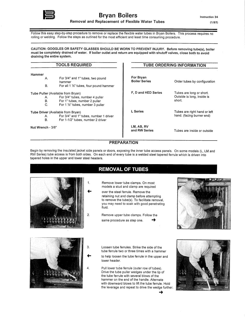
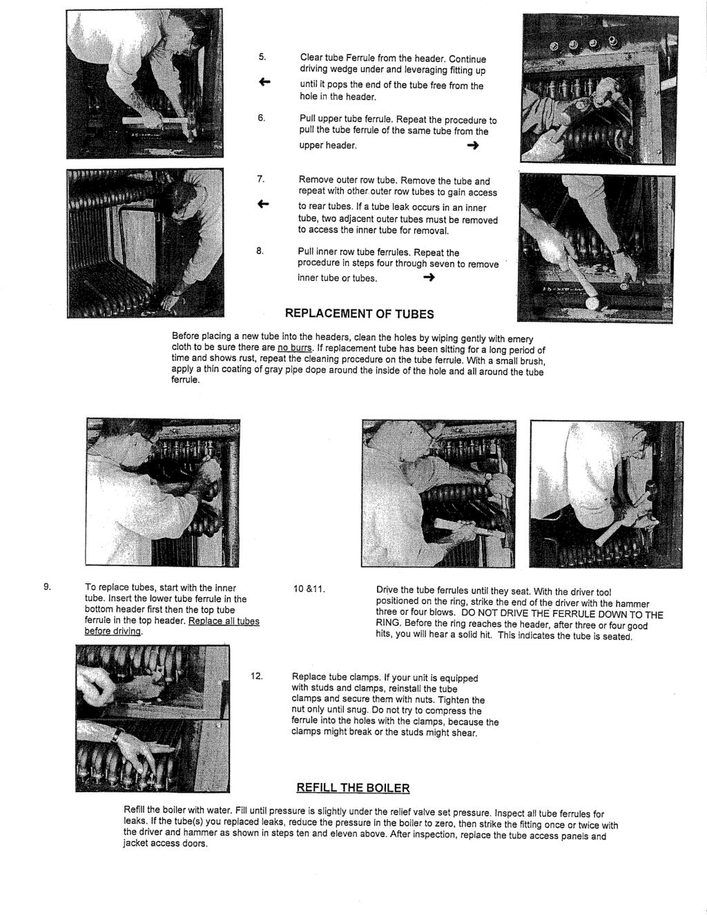
2 ASSEMBLY INSTRUCTIONS FOR BRYAN KNOCKDOWN BOILER AB SERIES BOLT TOGETHER WATER BOILERS FORM /29/2005 KD-1 Indicates the boiler is shipped completely assembled but constructed to be knocked down as necessary. Boiler bolted to base, to reassemble on job site. Care should be taken to observe disassembly procedure, since reassembly is exact reverse procedure. Consult instructions for reassembly. KD-2 Indicates the boiler partially disassembled after inspection, with controls, jacket and flue collector removed. The vessel has tubes installed, with the base and gas burners (atmospheric) installed. Each is crated separately and shipped for job site reassembly. (Boiler bolted to base.) Consult instructions for reassembly. KD-3 Indicates the boiler completely disassembled after inspection, with jacket and flue collector removed. The vessel has tubes removed. The base has gas burners (atmospheric) installed. Each is crated separately and shipped for job site reassembly. (Boiler bolted to base.) Consult instructions for reassembly. FOR REFERENCED ITEM # INDENTIFICATION, SEE DISASSEMBLED VIEW INCLUDED WITH THESE INSTRUCTIONS AB-BT Series, Forced Draft, Water Boilers Form 2346 Refer to section 8 for tools needed to complete assembly BOILER FOUNDATION Before uncrating, the boiler location should be prepared. The boiler should be set upon a good, level concrete floor. If the floor is not level or in good condition, a concrete foundation should be built, the dimensions to be slightly larger than the outside dimensions of the boiler. IMPORTANT: If the boiler is installed directly on a concrete floor where it is important that the floor be kept particularly cool, such as an upper floor or mezzanine, set the boiler up on insulating tile or steel framework, so air can circulate underneath. DO NOT INSTALL BOILER ON COMBUSTIBLE FLOORING. CAUTION DO NOT INSTALL BOILER ON CARPETING. CAUTION DO NOT RUN WIRING IN CONCRETE FLOOR UNDERNEATH BOILER. 1
 in place on cement pad.")


3 NOTICE BEFORE BOILER IS SET IN PLACE CONSULT INSTALLATION, OPERATION & MAINTENANCE MANUAL FOR PROPER CLEARANCES. 1.0 BOILER FRAME & TUBE INSTALLATION 1.1 Set boiler base assembly (Figure #1) in place on cement pad. Make sure that the base is properly positioned on the pad to assure the correct orientation of the Pressure Vessel assembly. NOTE: Boiler foundation information on page 1. Tube Access Rear 1.2 Position Pressure Vessel assembly onto the boiler base assembly. Steel brackets are welded onto Pressure Vessel to assist alignment of mating parts. When bolt alignment is complete, bolt the Pressure Vessel to base assembly. Do not tighten. See Figure 2. Front Side Figure 1 Alignment Bracket Bolt Figure 2 2

. Note: Tube holes must be lubricated before tubes are installed.")
4 1.3 Shipping braces shipped loose for KD-1, used only if needed. See Figure Next place a 24 long level across the top of the boiler outlet nozzle and make sure it is level on both X and Y axis. Tighten bolts from paragraph 1.2 after leveling is complete. The shipping braces are for shipping purposes only. Please remove after Pressure Vessel is positioned. 1.5 Bolt Base Pan onto Pressure Vessel assembly. Make sure Base Pan is setting level on Base assembly. NOTE: If boiler tubes are already installed, go to paragraph 2.0. Pressure Vessel Assembly Base Assembly Shipping Braces Base Pan Assembly 1.6 BOILER TUBE INSTALLATION - Applies only to KD-3 Construction (See attached instruction #34-3 tube replacement). Note: Tube holes must be lubricated before tubes are installed. It is recommended that a mixture of pipe dope and machine oil be mixed together and applied with a small paintbrush to each hole. X-Axis Y-Axis Figure 3 Inside Tube Outside Tube Outside Tube Inside Tube Front/Burner End Figure 4 3
 Square up the tube bank in order to assemble flue collector ends without difficulty. 1.9 (KD-3 only) Using a 2lb.")
 NOTE: Your state boiler inspector may require inspection of the boiler tubes under a hydrostatic test pressure of 1.")
5 1.7 (KD3 only) Next, install an inside tube (long neck down). Then install an outside boiler tube (short neck down.) Repeat this process until all boiler tubes are installed. See Figure (KD-3 only) Square up the tube bank in order to assemble flue collector ends without difficulty. 1.9 (KD-3 only) Using a 2lb. Hammer and tube driver tool, drive each tube into Pressure Vessel assembly. After all tubes have been driven, install tube clamps and nuts as required (KD-3 only) NOTE: Your state boiler inspector may require inspection of the boiler tubes under a hydrostatic test pressure of 1.5 times the maximum working pressure of the boiler (or 60 psig for boilers of 40 psig or less maximum working pressure.) If this inspection is required, it should be done now. CAUTION DO NOT DRIVE THE TAPERED TUBE FITTING EXCESSIVELY DEEP. THIS IS NOT UIRED TO ACHIEVE A GOOD SEAL. CAUTION THE HYDROSTATIC TEST PRESSURE MUST NOT EXCEED THE PRESSURE RATING OF THE TRIM AND CONTROLS ON THE BOILER. CHECK THESE RATINGS CAREFULLY. 2.0 INSULATION & TUBE BAFFLE INSTALLATION 2.1 Cut 2 monoblock insulation to tightly fit inside Base Pan. The Base Pan will need one layer of monoblock insulation (bottom) and one layer of white blanket insulwool insulation with the intention of filling the Base Pan cavity. 2.2 After monoblock and insulwool is placed inside Base Pan, cut 1 white blanket insulwool insulation to fit over the Base Pan and wrap over the stud sides. See Figure 5. Note: Flue collector will hold white blanket in place. Tube Access Side Boiler Base Pan 2 Monoblock Insulwool White Blanket Insulwool Cut white blanket to wrap over Base Pan Figure 5 4


 of the boiler. The flange on the upper baffle must be hooked over the endmost tube.")
6 2.3 Cut 1 Insulwool white blanket to tightly fit around down comers. Fold insulation to overlap a small amount around down comer. Construct insulation to come together inside combustion chamber toward front end therefore flue Collector front will hold insulation in position when bolted into place. Use tape to hold white blanket stationary until Flue Front is in position. See Fig 6 & 7. Down Comer Lower Saddle Bracket Upper Saddle Bracket Down Comer Tape Make insulation come together inside combustion chamber toward front or rear end. Figure 6 Figure Cut 1 Insulwool white blanket to closely fit around upper and lower drum saddle bracket. See Figures 6 & 7. Push studs through insulation in order to hold insulation in place. Upper Baffle 2.5 Place the upper tube baffle in position on top of the tubes at the rear end (opposite the burner end) of the boiler. The flange on the upper baffle must be hooked over the endmost tube. See Figure Place the lower tube baffle in position on the last pass of tubes at the front end (burner end) of the boiler. The flange on the lower baffle must be hooded over the front tube. See Figure 8. Vertical Baffle Burner End Lower Baffle Figure 8 5
7 2.7 See Figure 8 & 9 for vertical baffle location. Figure 9 also displays all AB Series baffle placement. The arrows indicate the path of flue gas through the boiler. 3.0 BOILER FLUE COLLECTOR INSTALLATION Figure 9 6


8 3.1 Arrange Flue Collector Front end onto Pressure Vessel and Base Pan Assembly. See figure 10. Do not tighten nuts until the whole flue collector is assembled with all nuts and bolts in place. 3.2 Install Flue Collector Rear end onto Pressure Vessel and Base Pan Assembly. See figure 10. Do not tighten nuts until the whole flue collector is assembled with all nuts and bolts in place. Top Panel Front End Rear End Side Panel Figure 10 Figure Install flue collector side panel/panels starting with panel closest to the front end. Place all nuts and bolts in place but do not tighten. 3.4 After front end, rear end, and side panel/panels are positioned, situate top panel in order for boltholes to line up. See figure 11. Install all nuts and bolts. After every nut and bolt is set, tighten all nuts and bolts. Note: Flue collector should be square with the Pressure Vessel. 3.5 Wrap Burner Plug flange with rope gasket. Place burner plug into Front End opening with the pressure tapping orientated to the top left corner. Figure 12 displays a Gordon Piatt burner plug. The burner plug MUST be properly packed with white blanket insulation or the manufacturers warranty is null and void. Figure 12 displays the proper procedure for packing a square opening. The easiest way to center burner plug in opening is to situate the bottom insulation into opening before the burner plug and then place burner plug on top of insulation. There must be no opening in the corners where the insulation intersects. After burner plug is in place, position clips to hold plug stationary. 3.6 Place peep site plug into Rear End of the flue collector. The peep site plug MUST be properly packed with white blanket insulation or the manufacturers warranty is null and void. Figure 12 displays the proper procedure for packing a square opening. The easiest way to center peep site plug in opening is to situate the bottom insulation into opening before the peep site plug and then place peep site plug on top of insulation. There must be no opening in the corners where the insulation intersects. See Figure 12. After peep sight plug is in place, position clips to hold plug stationary. 7
9 Fold 1 white blanket Insulation and pack on all sides of plug. Sheet metal guides Place both guides along side of plug. STEP 1 STEP 2 STEP 3 Remove all guides from plug. STEP 4 STEP 5 STEP 6 Use another sheet metal guide to drive insulation between the first two guides. NOTE: Repeat step 1-6 for all sides. Figure 12 8


10 3.7 Assemble the jacket top supports by screwing the supports to the ears welded on top of pressure vessel. Next, screw at least two sheet metal screws into the 5-1/4 long angles on the opposite end of jacket top support. The jacket top support and 5-1/4 angle will not be attached to the flue collector, but will rest on top. Note: Make sure 5-1/4 long angles do not interfere with nuts and bolts. See Figure 13. Weld Ear 5-1/4 Angle Jacket Support Figure Wrap Pressure Vessel and Flue Collector with yellow John s Mannsville insulation. The purpose of this insulation (not shown) is to guard the outside jacket from getting warm to the touch. Make sure the entire Pressure Vessel and Flue Collector is covered. 3.9 Cut yellow insulation for the top of boiler first. Allow the insulation to overlap the upper drum enough to almost touch the tubes. The jacket Door Bar panel will press the overlap against upper drum Starting on the Front End (Burner End), wrap yellow insulation horizontally around boiler. Start with Front End, then the Side, and then the Rear End. Do not wrap tube access side. Permit 6-10 to extend beyond the top. This overlap will be folded under the Jacket Top to ensure there is no open area in the corner. Punch welded sheet metal tabs (not shown) through yellow insulation and then bend tabs over to hold insulation in place. 4.0 BOILER JACKET INSTALLATION 4.1 Arrange boiler jacket top panel in place. Do not screw. 4.2 Place Jacket Side panel/panels upon the edge of the boiler base assembly. Position the flange of the Jacket Side to overlay Jacket Top. Align Jacket Side with the base assembly Jacket Front and Rear angles. See Figure 14. If boiler uses multiple Side panels, the panels should overlap one another. Use a pipe clamp to hold the top of the Side panel in position. See figure 15. Once alignment is complete, screw the bottom of the Side panel into the base assembly Jacket Side angle. Side overlay Top Jacket Front End Angle Jacket Rear End Angle Jacket Side Angle Figure 14 9


11 4.3 Situate Jacket Rear in place. The Rear End should slide over Jacket Top and Jacket Side. Make sure Rear is vertically level by using at least a 24 long level. Once jacket Rear is level, place one sheet metal screw in both top corners. Jacket Top Jacket Rear 4.4 Situate jacket Front in place. The Front should slide over Jacket Top and Jacket Side. Make sure Front is vertically level by using at least a 24 long level. Once jacket Front is level, place one sheet metal screw in both top corners. Align Side Panel w/ Base front angle Pipe Clamp Side Panels should overlap one another 4.5 Make sure again that jacket Front and Rear is level. Screw in the bottom of jacket Front and Rear about every 8. Next, screw along the rest of the top of jacket Front and Rear. Finally, screw in the top of jacket Side Panel. See figure 15. Jacket Side Figure Start inserting the Tube Access door closest to the Rear and insert doors working toward the Front. Now, fasten the Tube Access doors in place with the tube clamps and nuts. 4.7 Install Door Bar by sliding it between the yellow insulation wrap and jacket Top, Front and Rear. Secure Door Bar in place with provided sheet metal screws. See Figure Install both Jacket Door Filler bars but do not screw into place. Install all jacket Doors with a 1/16 gap and lock door latches. Square door Filler Bars by means of the door side in addition to about a 1/16 gap and screw Filler bars into place. Unlock door and confirm doors can be removed smoothly and easily. See Figure 16. Jacket Door Bar Door Latch Door Filler Bar 1/16 Gap Figure 16 10
 and pipe nipple(s). Rope FIGURE 17 4.")
12 4.0 FINAL ASSEMBLY 4.1 Install low water cut-off(s) and wire to control box. 4.2 Install heat transfer paste and low fire start aquastat sensor bulb (if provided) into immersion well. Replace retaining clops. Install any remaining wire moldings as required. 4.3 Install relief valve(s) and pipe nipple(s). Rope FIGURE Align the top of the burner control housing parallel with the floor going from left to right. Once the burner has been rotated to the correct position, check to see that the rope gasket on the plug is correctly positioned. Secure the burner assembly in position and clamp in place with the clamps and nuts provided. 4.5 Wire the forced draft burner, gas valves, and high/low gas pressure switches or any other components as required. Refer to the wiring diagram(s) provided with the boiler. 11
13 5.0 CONNECTIONS 5.1 Refer to Form IM-8: Installation, Operation and Service Manual. 5.2 Connect all fuel and water (or steam) piping and electrical connections as required. Refer to Form IM-7R for recommended practice. 5.3 Perform hydrostatic test of boiler and pressure test of fuel piping as directed in Form IM Be certain that proper provision has been made for combustion air and flue gas venting as directed in IM Make certain that the boiler room is always at a neutral or positive pressure relative to outdoors and that the stack is properly installed and designed to avoid downdrafts. The Boiler cannot function in a negative pressure room or under conditions of sustained downdraft without the use of carefully designed and selected mechanical draft equipment. 6.0 CLEANING THE BOILER AND SYSTEM 6.1 Refer to Section 3 of Form IM Care must be taken on old systems to clean all piping and system components to remove all sediment. Be certain that there are no leaks and that the air removal and expansion tank system are functional. Install a cartridge filter and inspect it frequently for debris. 7.1 Refer to section 2 of IM START-UP AND OPERATION IMPORTANT THIS EQUIPMENT SHOULD BE STARTED AND ADJUSTED BY A QUALIFIED BURNER TECHNICIAN. COMBUSTION DATA SHOULD BE TAKEN AND RECORDED ON THE START-UP REPORT FORM SUPPLIED IN THE BOILER MANUAL. THIS IS ESSENTIAL FOR SAFE AND PROPER OPERATION OF THIS BOILER. 8.0 TOOLS NEEDED FOR ASSEMBLY 1.) ¼ Nut Driver 7.) 24" Level 2.) #26 Drill Bit 8.) 2 Pound Hammer 3.) Electric Drill 9.) Tube Driver 4.) Adjustable Wench 10.) Tube Puller 5.) Ratchet Wench 11.) 35" Pipe Clamp 6.) 9/16" Deep Socket 12
14
15 EFF DATE: 3/26/05 REPL.: NEW AB BOLT TOGETHER FORCED DRAFT - WATER FORM: 2346 PAGE: AB - BT - FD - W - 1 PARTS LIST AB90-W AB120-W AB150-W AB200-W AB250-W AB300-W DESCRIPTION PART PART PART PART PART PART NO. NO. NO. NO. NO. NO. 1 PRESSURE VESSEL - (With Tubes) Pressure Vessel Downcomer Insulation ITEM BOILER TUBE ASSEMBLY 3 Boiler Outside Tube Boiler Inside Tube Boiler Tube Studs (3/8"-16 x 2-3/8") Tube Clamp Tube Clamp Nut (3/8") BOILER BASE 5 Boiler Base Assembly Floor Pan Assembly FLUE COLLECTOR PANELS 7 Flue Collector - Front Assembly Flue Collector - Rear Assembly Flue Collector - Side Starter Panel Assembly S S S S S 10 Flue Collector - Side Center Panel Assembly C C 11 Flue Collector - Side End Panel Assembly E E E E E 12 Flue Collector - Top Front Assembly Flue Collector - Top Rear Flue Collector - Outside Wrap Insulation Flue Collector - Peep Site Plug Flue Collector - Peep Site Plug Insulation TUBE BAFFELS 17 Upper Horizontal Tube Baffel Lower Horizontal Tube Baffel Upper Vertical Tube Baffel Lower Vertical Tube Baffel TUBE ACCESS PANELS 21 Tube Access Starter Panel Assembly Tube Access Filler Panel Assembly Tube Access Burner Panel Assembly
16 EFF DATE: 3/26/05 REPL.: NEW ITEM AB BOLT TOGETHER FORCED DRAFT - WATER FORM: 2346 PAGE: AB - BT - FD - W - 2 PARTS LIST AB90-W AB120-W AB150-W AB200-W AB250-W AB300-W DESCRIPTION PART PART PART PART PART PART NO. NO. NO. NO. NO. NO. 24 JACKET DOOR Jacket Access Door Assembly (#1) Jacket Access Door Assembly (#2) Jacket Access Door Assembly (#3) Jacket Access Door Assembly (#4) Jacket Access Door Assembly (#5) Jacket Access Door Assembly (#6) JACKET PANELS 25 Jacket Front (Burner End) Jacket Rear (Peep Site End) Jacket Side (First Panel) Jacket Side (Second Panel) Jacket Top Jacket Door Filler Strip Jacket Door Bar Jacket Peep Site Overlay Jacket Peep Site Ovservation Port Overlay Jacket Support Jacket Support Bracket BURNER ASSEMBLY BURNER - See Burner Parts Data Sheet REFER TO EQUIPMENT LIST 36 Burner Plug Contact Bryan Steam with burner model and manufacture information 37 Burner Plug Filler Insulation Rope Gasket (Ft.) CONTROL EQUIPMENT LIST Junction Box w/cover or Control Box Terminal Strip * Aquastat - Operator CONSULT EQUIPMENT LIST Aquastat - High Limit Aquastat Well Low Water Cut Off Wire Molding WATER TRIM Comb.Temp/Press.Gauge Pressure Relief Valve CONSULT EQUIPMENT LIST
17 EFF DATE: 3/26/05 REPL.: NEW ITEM FORM: 2346 FORCED DRAFT - WATER PAGE: AB - BT - FD - W - 2 PARTS LIST AB90-W AB120-W AB150-W AB200-W AB250-W AB300-W DESCRIPTION PART PART PART PART PART PART NO. NO. NO. NO. NO. NO. AB BOLT TOGETHER INDIRECT WATER HEATER Heat Exchanger Gasket 8" Indirect Heat Exchanger Expansion Tank Boiler Fill Valve CONSULT EQUIPMENT LIST Heat Exchanger Relief Valve (WT ONLY) Pool Water Temperature Control (WP ONLY) SERVICE TOOLS Tube Puller ** Tube Driver ** Tube Brush ** * Depends on Number of Terminals Required ** Not Standard. Available Upon Request.
18
19
20


 previously used to drive 1 tubes will adequately drive 1 end-formed tubes only.")

21 Bryan Boilers Installation and Operating Service Manual Supplement Form # 2390 Date: 04/10/12 Replaces: 11/06/09 Bryan Boilers is currently supplying boilers with product enhancements to our flexible tubes. Most flexible tubes will no longer have a separate ferrule welded to each end. We have developed a way to form the ferrule from the tube material directly on the bent tube see figure 1. We will identify these tubes as End-Formed. Patent Pending A B C A B The new driver and current tube pullers will work for all tubes regardless if end-formed or welded ferrule. We have changed to end-formed tubes for the following boilers, DR, AB, RV, and RW. The Triple-Flex boiler has shipped with endformed tubes since introduction. The table below is provided as a crossreference until the parts list can be revised with the new numbers. A. 1 End-Formed Tube. B. Triple-Flex End-Formed Tube. C. 1-1/2 End-Formed Tube. These tubes will require a specific driver to install the tubes into the boiler vessel. The tube driver required is shown in Figure 2. This driver is required to drive all endformed tubes. The driver (see Figure 3) previously used to drive 1 tubes will adequately drive 1 end-formed tubes only. If you have a driver that looks like Figure 4 B, your driver will need to be modified by grinding to match Figure 4 A. NOTE: If you order tubes with old part number, you will receive end-formed tube replacements. End-Formed Tube Cross Reference Boiler Series Outside or Inside With Fittings (Old Part#) End-Formed (New Part#) DR Outside DR Inside CLM N/A CL N/A AB Outside AB Inside RV Outside RV Inside RW Outside RW Inside K Outside N/A K Inside N/A Tube Driver
22
TITAN Fuel Tanks. INSTALLATION INSTRUCTIONS G e n e r a t i o n V
 TITAN pt. no.: 02 0000 0128 Important: Please read these instructions carefully and completely before starting the installation. TITAN Fuel Tanks INSTALLATION INSTRUCTIONS G e n e r a t i o n V Extended
Uptown Fire Pit Table
 Uptown Fire Pit Table Installation Instructions 1 P a g e Contents Contents..2 Required Tools..3 Placing and assembling the Table. 4 Gas Connection..5 Igniter Installation....6 Locating Propane tank 8
Otter Pro X-Over Lodge Installation and Set-Up Instructions
 Otter Pro X-Over Lodge Installation and Set-Up Instructions Otter Pro X-Over Lodge Fits Magnum Otter II & Pro Sled Only Parts Identification and Check List MODEL NUMBERS: Complete Pkg Pro X-Over Lodge
Napa Valley Fire Pit Table
 Napa Valley Fire Pit Table 48 x48 Model Installation Instructions For Models: NAPA-VALLEY-2424-K, NV-2424-BRN-K, NV-2424-BLK-K, NV-2424-GRY-K, NV-2424-BLK-W-K 1 P a g e Contents Contents..2 Required Tools..3
Colonial and Grand Colonial Fire Pit Tables. Installation Instructions for
 Colonial and Grand Colonial Fire Pit Tables Installation Instructions for Colonial-48-M-K, Col-48-MNB-K, Grand-Colonial-48-K, CM-48-DIN-K, MNB-48-DIN-K, GC-48-DIN-K, CM-48-PUB-K, MNB-48-PUB-K, GC-48-PUB-K
Otter Pro XT Cabin Installation and Set-Up Instructions
 Otter Pro XT Cabin Installation and Set-Up Instructions Otter Pro XT Cabin Fits Medium Otter Pro and Otter II Sled Only Parts Identification and Check List MODEL NUMBERS: Complete Pkg Pro XT Thermal Cabin
TCWS54 SEE THRU DIAMOND BURNER INSTALLATION KIT INSTRUCTIONS
 INSTALLER: Leave this manual with the appliance. CONSUMER: Retain this manual for future reference. These instructions are supplementary to the Installation and Operating Instructions supplied with the
DO NOT USE WITH CROSSBAR SPREAD LESS THAN 24.
 TM Please read all instructions carefully before assembly, installation and/or use of this product. DO NOT USE WITH CROSSBAR SPREAD LESS THAN 24. WARNING: Do not exceed the weight limit of your vehicle
Thermostatic Griddle Field Service Kit Instructions
 Thermostatic Griddle Field Service Kit Instructions The following document provides instructions on how to install a Garland Thermostatic Griddle Field Kit and is applicable to each 2 section of a Garland
User s Manual Trampoline 8
 User s Manual Trampoline 8 Model! WARNING Read all precautions and instructions in this manual before using this equipment. Save this manual for future reference. Maximum user weight 17 lbs. ASSEMBLY IMPORTANT
Gas Conversion Kits and Instructions
 Gas Conversion Kits and Instructions INSTALLATION FORM RGM 432/433-GC (Version D.1) Obsoletes Form RGM 432/433-GC (Version D) APPLIES TO: Model FT and Model SFT All gas conversion must be done by a qualified
TCWS.38NG03.C BLACK DIAMOND BURNER KIT INSTRUCTIONS
 IMPORTANT: THESE INSTRUCTIONS ARE TO REMAIN WITH THE HOMEOWNER These instructions are supplementary to the Installation and Operating Instructions supplied with the fireplace and should be kept together.
14' x 32' x 12' Round Top Round Style Shelter Assembly Instructions
 14' x 32' x 12' Round Top Round Style Shelter Assembly Instructions Description Model # 14' x 32' x 12' RoundTop Garage - Gray 62669 Recommended Tools Please read instructions COMPLETELY before assembly.
Standard Awning Installation Instructions
 Standard Awning Installation Instructions Important Note: Please become familiar with this entire document BEFORE beginning your installation. The time you spend doing this is well spent and will make
INSTALLATION INSTRUCTIONS
 INSTALLATION INSTRUCTIONS KR54, KR1654, & KR4954 Keyed Removable Mullion NOT FOR USE ON ELECTRIC OR FIRE RATED MULLIONS. This kit includes the following parts: (Not to scale) WARNING Remove key, reinstall,
TC36 CHALET BURNER KIT INSTALLATION INSTRUCTIONS
 INSTALLER: Leave this manual with the appliance. CONSUMER: Retain this manual for future reference. These instructions are supplementary to the Installation and Operating Instructions supplied with the
MYRIAD Banner Stand is a trademark of Skyline Exhibits. Patent Pending PN32294-B. MYRIAD Banner Stand
 is a trademark of Skyline Exhibits Patent Pending 1.1 1. Banner Stand Setup 1.1 Remove banner stand from standard case or Arrive Portable Display & Workstation and assemble pole. 1.2 Insert pole into base
Door Bushing Replacement & Latch Adjustment Monaco Group Coaches
 Door Bushing Replacement & Latch Adjustment Monaco Group Coaches Contents Door Latch Adjustment & Repair... 1 Symptoms:... 1 Replacing the bushing VS. Adjusting the latch rods.... 1 How the bushing works....
BERYL Service Guide. Travel Adjust OTT Change
 BERYL Service Guide Travel Adjust OTT Change SERVICE OVERVIEW This manual will guide you step by step performing a travel adjust and OTT setting change to your Beryl suspension fork. Please follow each
Shut off combine and remove key before installing the hopper extension. Make sure the combine is on a level surface. Engage parking brake.
 ASSEMBLY INSTRUCTIONS CASE IH 5088, 6088/7088, 7010/8010 & 7120/8120/9120 Series NEW HOLLAND CR STD Series Combines (Large) big top 26301(service only), 29976 (service only), 53408, 53543 & 54274 The Crary
TC30 HEARTWOOD BURNER INSTALLATION INSTRUCTIONS
 INSTALLER: Leave this manual with the appliance. CONSUMER: Retain this manual for future reference. These instructions are supplementary to the Installation and Operating Instructions supplied with the
TC36 CHALET II BURNER KIT INSTALLATION INSTRUCTIONS
 INSTALLER: Leave this manual with the appliance. CONSUMER: Retain this manual for future reference. These instructions are supplementary to the Installation and Operating Instructions supplied with the
AND LOAD CANOPY RACK SPECIFICATIONS
 8MAY15 INSTRUCTIONS for the LOCK AND LOAD CANOPY RACK SPECIFICATIONS and SAFE LOADING REQUIREMENTS The Lock and Load ladder carrier for Truck Caps is a rack designed to mount to the top of a pickup truck
INSTRUCTIONS FOR MVK-NQM PILOT KIT
 MVK-NQM IMPORTANT READ AND UNDERSTAND THESE INSTRUCTIONS BEFORE INSTALLING These instructions must be used as a supplement to the instructions supplied with your gas log set. Follow the Gas Log Set instructions
Advantage Plus TIM-3600 Series Reel
 Read the following precautions and instructions before you begin assembly or using. Failure to comply with these instructions could result in personal injury or property damage. Keep these instructions
* * KR54-F, KR9854 & KR9954 Installation Instructions. Read All Warnings Before Starting Installation! Index:
 *941061-00* 941061-00 Keyed Removable Mullion KR54-F, KR9854 & KR9954 Installation Instructions CLASSIFIED CLASSIFIED C Read All Warnings Before Starting Installation! Index: General Information ----------------
Otter XT 650 Cabin Installation and Set-Up Instructions
 Otter XT 650 Cabin Installation and Set-Up Instructions Otter XT 650 Cabin Fits Medium Otter Wild Sled Only Parts Identification and Check List MODEL NUMBERS: Complete Pkg Otter XT 650 Cabin 200891 2 1
CONVEX Awning Instructions
 CONVEX Awning Instructions IMPORTANT NOTE: Please take a few minutes to become familiar with this entire document BEFORE beginning your installation. The time you spend doing this is well spent and will
Model 205 Fireview Maintenance Kit
 Model 205 Fireview Maintenance Kit Please read all of the instructions before you begin the procedure. Confirm that you have all the necessary tools and parts required. Allow about one hour to complete
SERVICE MANUAL V-SERIES HEAVY DUTY BROILERS, DOUBLE DECK AND RANGE MATCH MODELS - NOTICE - For a complete listing of models, see the MODELS section.
 SERVICE MANUAL V-SERIES HEAVY DUTY BROILERS, DOUBLE DECK AND RANGE MATCH MODELS For a complete listing of models, see the MODELS section. - NOTICE - This Manual is prepared for the use of trained Vulcan
For converting 72 PKN for use with (LP) propane gas.
 propane gas.") IMPORTANT READ AND UNDERSTAND THESE INSTRUCTIONS BEFORE INSTALLING These instructions must be used as a supplement to the instructions supplied with your gas log set. Follow the Gas Log Set instructions
IMPORTANT READ AND UNDERSTAND THESE INSTRUCTIONS BEFORE INSTALLING These instructions must be used as a supplement to the instructions supplied with your gas log set. Follow the Gas Log Set instructions
LITE Spear Awning Instructions
 LITE Spear Awning Instructions IMPORTANT NOTE: Please take a few minutes to become familiar with this entire document BEFORE beginning your installation. The time you spend doing this is well spent and
WARNING Do not obstruct the flow of combustion and ventilation air to and from your oven. There must be no obstructions around or underneath the oven.
 SECTION 2 SECTION 2 WARNING Do not obstruct the flow of combustion and ventilation air to and from your oven. There must be no obstructions around or underneath the oven. CAUTION For additional installation
Otter XT Cabin Installation and Set-Up Instructions
 Otter XT Cabin Installation and Set-Up Instructions Otter XT Cabin Fits Medium Otter Wild Sled Only Parts Identification and Check List MODEL NUMBERS: Complete Pkg Otter XT Cabin 200962 2 1 PARTS LIST
Key Largo Fire Pit. Installation Instructions. 1 P a g e. NorthlineExpress.com. Toll-Free
 Key Largo Fire Pit Installation Instructions 1 P a g e Contents Contents..2 Required Tools..3 Placing and assembling the Table. 4 Gas Connection..5 Igniter Installation....6 Locating Propane tank 8 Finishing
Otter Pro XT 1200 Cottage Installation and Set-Up Instructions
 Otter Pro XT 1200 Cottage Installation and Set-Up Instructions Otter Pro XT 1200 Cottage Fits Small Ultra-Wide Otter Pro and Otter II Sled Only Parts Identification and Check List MODEL NUMBERS: Complete
BILLY GOAT KV HOSE KIT (P/N ) PURPOSE: To allow for vacuuming in hard to reach places.
 PURPOSE: To allow for vacuuming in hard to reach places.") BILLY GOAT KV HOSE KIT (P/N 891125) PURPOSE: To allow for vacuuming in hard to reach places. Part No 891061-1 - Form No F052209A INSTALLATION: Step 1. Attach nozzle wear guards. 1. Disconnect spark plug
BILLY GOAT KV HOSE KIT (P/N 891125) PURPOSE: To allow for vacuuming in hard to reach places. Part No 891061-1 - Form No F052209A INSTALLATION: Step 1. Attach nozzle wear guards. 1. Disconnect spark plug
* * 4023 KR. Step 1 Prepare the Keyed Removable Unit. Not for use on electric or fire rated removable mullions
 condition. *64009-00* 64009-00 Keyed Removable Mullions 403 KR Installation Instructions Not for use on electric or fire rated removable mullions This kit includes the following parts: (Not to scale) 5/6
An Improved Pedestal To A Version One Worksurface
 Steelcase, Inc. Grand Rapids, MI 49501 U.S.A. 1-888-783-3522 An Improved Pedestal To A Version One Worksurface NOTE: This installation applies to 25, 30, and 35 deep worksurfaces with lock rail only. VERSION
Solar Power Shade INSTRUCTION MANUAL
 INSTRUCTION MANUAL 20 June 2006, Revision Initial Release 26 September 2006, version 2 Powerfilm, Inc. 2337 230th Street Ames, IA 50014 (515) 292-7606 Web Site: www.powerfilmsolar.com Table of Contents
ASSEMBLY GUIDE. Customer Service: INCH² 2-BURNER & 864 INCH² 2-BURNER
 ASSEMBLY GUIDE 688 INCH² 2-BURNER & 864 INCH² 2-BURNER DANGER If you smell gas: 1. Shut off gas to the appliance. 2. Extinguish any open flames. 3. Open lid. 4. If odor continues, keep away from the appliance
300 ft. 5/8 Hose wagon
 300 ft. 5/8 Hose wagon Model 95956 Assembly And Operation Instructions Due to continuing improvements, actual product may differ slightly from the product described herein. (Garden hose is not included).
Boardwalk Fire Pit Table
 Boardwalk Fire Pit Table Installation Instructions 1 P a g e Contents Required Tools....3 Placing the Table 5 Gas Connection..6 Igniter Installation (pt 1)...7 Fire Pit Assembly....8 Igniter Installation
SOLHARO ASSEMBLY & INSTALLATION INSTRUCT IONS
 A. Introduction: SOLHARO ASSEMBLY & INSTALLATION INSTRUCT IONS Rev. 01/30/2012 The Solharo is an external, retractable, tensioned sun shading system designed to fit over a sunroom or wood pergola. The
r e - p a r t s. c o m
 Owner s Manual SPK3E - Manual EASY Control General Assembly, Installation, and Operation Instructions for use with Natural Gas Burners; F, FX, CS, CXF, TNA or Propane Gas Burners: FA, FAX, CA, CXFA, TNA/LP
Auxiliary 63.5l Fuel Tank Ford/Mazda Pick-up Truck 2012-Current READ ME! IMPORTANT WARNING!
 Auxiliary 63.5l Fuel Tank Ford/Mazda Pick-up Truck 2012-Current ENG FTFM006 90 min READ ME! Thank you for purchasing a Front Runner Ford/Mazda Pick-Up Truck 2012 - Current Fuel Tank. Before you start,
ELECTRA MAGIC RV and Marine Recirculating Toilets
 ELECTRA MAGIC RV and Marine Recirculating Toilets Because We Take Your Leisure Seriously Electrical Hookup RV and Marine Models Connect your 12-Volt or 24-Volt model Electra Magic directly to the appropriate
CONVERSION INSTRUCTIONS
 CONVERSION INSTRUCTIONS Natural Gas to Propane Gas Conversion Kit For Thermador Professional Cooktops and Ranges Model STARLPKIT Part No. 35-00-682 Contains 7mm Hex Main Orifices This kit is used to convert
HARD DOOR UPGRADE KIT
 RV Accessories OWNER'S MANUAL HARD DOOR UPGRADE KIT FOR ADD-A-ROOM & BREEZEWAY SCREEN ROOMS THIS MANUAL SUPPLEMENTS THE ADD-A-ROOM INSTRUCTIONS TABLE OF CONTENTS First Time Assembly... 2 Assembling the
SPK3E - Manual EASY Control
 SPK3E - Manual EASY Control General Assembly, Installation, and Operation Instructions for use with Natural Gas Burners; F, FX, CS, CXF, TNA or Propane Gas Burners: FA, FAX, CA, CXFA, TNA/LP LISTED BY
Solera Classic Awning OEM INSTALLATION MANUAL
 Solera Classic Awning OEM INSTALLATION MANUAL TABLE OF CONTENTS System and Safety Information 2 Preparation 3 Resources Required 3 Installation 3 Installing the Awning Rail (If Necessary) 3 Assembling
APPENDIX A LIGHT SOURCE
 APPENDIX A LIGHT SOURCE GASOLINE LANTERN One source of artificial light for the field kitchen is the gasoline lantern (NSN 6260-00-170-0430). It is a one-mantle lantern with a heat-resistant globe or globe
JOINING MULLION (DIRECT MULL) ASSEMBLY INSTRUCTIONS FOR 3-WAY OR 4-WAY JOINTS FOR IMPERVIA AWNING, CASEMENT AND LARGE AWNING
 ASSEMBLY INSTRUCTIONS FOR 3-WAY OR 4-WAY JOINTS FOR IMPERVIA AWNING, CASEMENT AND LARGE AWNING") 2014 Pella Corporation JOINING MULLION (DIRECT MULL) ASSEMBLY INSTRUCTIONS FOR 3-WAY OR 4-WAY JOINTS FOR IMPERVIA AWNING, CASEMENT AND LARGE AWNING For Additional Mullion Assembly Information; Visit www.installpella.com/mullions,
2014 Pella Corporation JOINING MULLION (DIRECT MULL) ASSEMBLY INSTRUCTIONS FOR 3-WAY OR 4-WAY JOINTS FOR IMPERVIA AWNING, CASEMENT AND LARGE AWNING For Additional Mullion Assembly Information; Visit www.installpella.com/mullions,
Product instruction manual Ream Cutting Systems RE3943, RE3946, RE3947, RE3971, RE3952E
 Product instruction manual Ream Cutting Systems RE3943, RE3946, RE3947, RE3971, RE3952E The Trimfast Ream Cutters are reliable, high performance cutters that will give you the results you need quickly
INSTANT GARAGE MODEL NO: CIG81224 ASSEMBLY INSTRUCTIONS PART NO: ORIGINAL INSTRUCTIONS
 INSTANT GARAGE MODEL NO: CIG81224 PART NO: 3503578 ASSEMBLY INSTRUCTIONS ORIGINAL INSTRUCTIONS GC1117 INTRODUCTION Thank you for purchasing this CLARKE Instant Garage. When erected, the CIG81224 garage
Tank. Part B, Section 1. This section covers the following unit configurations. Pump Piston Pump (E or G)
") Part B, ection Model Voltage This section covers the following unit configurations. 3400V All Pump Piston Pump (E or G) Manifold Control 4-Port (A) Vista tandard (V) Vista Pattern (PC) Vista Temperature
Part B, ection Model Voltage This section covers the following unit configurations. 3400V All Pump Piston Pump (E or G) Manifold Control 4-Port (A) Vista tandard (V) Vista Pattern (PC) Vista Temperature
TCWS54 SEE THRU LONG BEACH LOG INSTALLATION INSTRUCTIONS
 INSTALLER: Leave this manual with the appliance. CONSUMER: Retain this manual for future reference. These instructions are supplementary to the Installation and Operating Instructions supplied with the
Assembly/Installation/Use Instructions:
 IMPORTANT We highly recommend that our products be installed and serviced by professionals who are certified in the U.S. by NFI (National Fireplace Institute) or in Canada by WETT (Wood Energy Technical
Urea/Adblue Hose Reel
 www.scintex.com.au sales@scintex.com.au Model: SHR3408 Urea/Adblue Hose Reel Product Manual Specifications Spring driven drum: for automatic rewind. Locking ratchet: to maintain the desired length of hose
General Purpose Shelter
 General Purpose Shelter 0' x 0' x ' ( x x. m) ASSEMBLY MANUAL Model NO.: - Tools required for assembly (not included) TM TABLE OF CONTENTS Important safety instructions... Intended use... Parts list......
Gas Go Anywhere /23/01
 Gas Go Anywhere 55014 02/23/01 FOR OUTDOOR USE ONLY This grill does not include an LP fuel tank. Check Package Contents You should have received the parts listed below. While we give much attention to
TC42 CHALET II BURNER KIT INSTALLATION INSTRUCTIONS
 INSTALLER: Leave this manual with the appliance. CONSUMER: Retain this manual for future reference. These instructions are supplementary to the Installation and Operating Instructions supplied with the
NEWMAR SERVICE SCHOOL
 NEWMAR SERVICE SCHOOL TRAINING INFORMATION GUIDELINE FOR FEBRUARY 2013 OUR PRODUCTS: NOVA DUAL PITCH AWNING G-2000/ G-1500 2 P a g e G-2085 G-5000 3 P a g e G-LINKS 4 P a g e NOVA/ G-2000/ G-1500 BASIC
Installation Instructions for. Thrifty King CT Series Fountains
 Installation Instructions for Thrifty King CT Series Fountains Congratulations, you have just purchased the finest watering fountain on the market. This unit is built to give you excellent service when
Installation Instructions for. Thrifty King CT Series Fountains
 Installation Instructions for Thrifty King CT Series Fountains Congratulations, you have just purchased the finest watering fountain on the market. This unit is built to give you excellent service when
Therme storage water heater. Table of contents. Symbols used. Symbols used Symbol indicates a possible hazard. Installation instructions
 Therme storage water heater Table of contents Symbols used... 8 Installation instructions Water supply... 9 Choice of location... 9 Installation of the Therme... 9 Fitting the draining and venting valve...
INSTALLATION INSTRUCTIONS for vertical awnings
 Custom made Awnings and Blinds Item No 0759 INSTALLATION INSTRUCTIONS for vertical awnings IMPORTANT INFORMATION BEFORE INSTALLING YOUR Updated 08/09/15 AN AWNING INSTALLATION IS A HOME IMPROVEMENT PROJECT
The Cove Fire Pit. Installation Instructions for CV-30
 The Cove Fire Pit Installation Instructions for CV-30 1 2 IMPORTANT Contents Please consult your Crystal Fire Burner Owner s instruction manual for detailed instructions and important information related
Maintenance 45 Serie CAUTION. Before resetting your electronic card that displays an error code.
 29-10-2013 CAUTION Before resetting your electronic card that displays an error code. Error Code H Service the stove COMPLETELY as described in this manual. Check the chimney pipe. Error Code O Service
S E L E C T I O N. Abdominal Crunch. User manual
 and S E L E C T I O N T H E S T R E N G T H E V O L U T I O N User manual and and The identification plate of the and manufacturer, affixed along side the seat on the frame of the weight stack, gives the
Thomas Scientific Swedesboro, NJ U.S.A.
 Thomas Scientific Swedesboro, NJ 08085-0099 U.S.A. Wiley Laboratory Mill, Model 4 3375-E10 (115 V, 50/60 HZ) USE AND CARE OF CATALOG NUMBER: 3375-E10 Wiley Laboratory Mill, Model 4 (115 V, 50/60 HZ) UNPACKING
INSTALLATION INSTRUCTIONS
 INSTALLATION INSTRUCTIONS Pictures in this manual are shown with the optional visual display indicator installed on the filter. BLUE FLAME & BLUE FLAME II MAXX LP FILTER KIT (423-375-001A) SHIVVERS SHIVVERS
INSTALLATION INSTRUCTIONS for folding arm awnings
 Custom made Awnings and Blinds Item No 0757 INSTALLATION INSTRUCTIONS for folding arm awnings IMPORTANT INFORMATION BEFORE INSTALLING YOUR Updated 08/09/15 AN AWNING INSTALLATION IS A HOME IMPROVEMENT
Kontrol Kube Advanced Owners Manual
 Mobile Containment. Simplified. TM Kontrol Kube Advanced Owners Manual KONTROL KUBE www.kontrolkube.com 800.343755 1 IMPORTANT SAFETY INFORMATION SAVE THESE INSTRUCTIONS. CAREFULLY READ AND FOLLOW THESE
Stonefire Fire Pit Table. Installation Instructions for SF-32-K
 Stonefire Fire Pit Table Installation Instructions for SF-32-K / 1 2 IMPORTANT Please consult your Crystal Fire instruction manual for detailed instructions and important information related to the burner
RMC1E - Variable Flame Height EASY Control
 Owner s Manual RMC1E - Variable Flame Height EASY Control General Assembly, Installation, and Operation Instructions for use with Natural Gas Burners; F, FX, CS, CXF, TNA or Propane Gas Burners: FA, FAX,
DIAMOND TECH INTERNATIONAL Innovations For Creativity DIAMOND LASER BAND SAW OPERATIONS MANUAL
 SPEEDSTER-XL INSTRUCTION MANUAL DIAMOND TECH INTERNATIONAL Innovations For Creativity SPEEDSTER-XL DIAMOND LASER BAND SAW OPERATIONS MANUAL SPEEDSTER-XL INSTRUCTION MANUAL - PAGE 1 Before You Begin Read
Installation and operation instructions for KINEMAX burners
 -. - Installation and operation instructions for KINEMAX burners Application requirements View port A view port to observe burner flame is essential to inspect the flame aspect. Locate the view port downstream
Mazdaspeed6 Stage 1 Location 2 OCC Kit Install guide
 1 Mazdaspeed6 Stage 1 Location 2 OCC Kit Install guide WARNING: By installing this Product, you understand that: The buyer/user assumes all risk as to quality, performance and use of these products and
Capacity kw. Thermal turndown from specified maximum capacity 8:1 8:1
 3-18.3-5 Specifications of OXY-THERM TITAN burners Typical burner data Fuel: natural gas at 15 C with 10.9 kwh/nm 3 HHV - sg = 0.6 Oxygen: 90-100% purity Stated pressures are indicative. Actual pressures
Brooks Fire Pit Table. Installation Instructions for Brooks Fire Pit Table BRK-1224
 Brooks Fire Pit Table Installation Instructions for Brooks Fire Pit Table BRK-1224 1 IMPORTANT Contents Please consult your Crystal Fire instruction manual for detailed instructions Required and important
ASSEMBLY GUIDE. Customer Service: INCH² 3-BURNER & 545 INCH² 3-BURNER
 ASSEMBLY GUIDE 455 INCH² 3-BURNER & 545 INCH² 3-BURNER DANGER If you smell gas: 1. Shut off gas to the appliance. 2. Extinguish any open flames. 3. Open lid. 4. If odor continues, keep away from the appliance
Genesis. Side Burner Accessory Installation. Step 3. Step 1. Step 2. For use with Genesis Gas Barbecues Only
 Genesis Side Burner Accessory Installation For use with Genesis Gas Barbecues Only Step 1 WARNING: All gas controls and supply valves should be in the OFF position. You will need: Side burner assembly
FLEX KEY ASSEMBLY. ..._ o RAFTER ARM TUBE MAIN ARM TUBE CAP NUT CLAW HINGE
 ZIP DEE Inc. 96 Crossen Ave. Elk Grove Village, IL 60007(847)437-0980 (800)338-2378 HEAD CASTING AWNING RAIL FLEX KEY ASSEMBLY..._ o GM1 Installation Instruction GMC Motorhome RAFTER ARM TUBE MAIN ARM
BR B Bike Rack Instructions
 IMPORTANT NOTE: It is common that vehicles with lids and hatches have a single rear wiper. It is important that you make yourself aware that the wiper cannot be used while the rack is attached to the vehicle.
Fire Pit Tables. Installation Instructions. Sierra, San Juan, Grandstone, Rivers Edge, Pike s Peak. 1 P a g e
 Fire Pit Tables Sierra, San Juan, Grandstone, Rivers Edge, Pike s Peak Installation Instructions 1 P a g e Contents Contents..2 Required Tools...3 Placing the Table.. 4 Gas Connection..5 Igniter Installation....6
Installation Instructions
 Installation Instructions C 710 www.contura.eu 50 CERTIFICATE Declaration of performance according to Regulation (EU) 305/2011 No. C710-CPR-160329-SE-1 PRODUCT Product type Stove lit with solid biofuels
Installation Guide. LPKPDR - Universal LP Conversion Kit for Professional & Designer Ranges/Rangetops. Viking Range, LLC.
 Installation Guide Viking Range, LLC 111 Front Street Greenwood, Mississippi 38930 USA (662) 455-1200 For product information, call 1-888-845-4641 LPKPDR - Universal LP Conversion Kit for Professional
Installation instruction
 Installation instruction Ci51 116 FACTS Technical specifications Model i51 Log box (option) Output 6-11 kw Nominal output 8 kw Efficiency 80 % Weight (kg) 215 50 Powerstone (option): + 100 kg Width (mm)
FORCE 10 MARINE BARBEQUES
 FORCE 10 MARINE BARBEQUES PROPANE MODELS Model 3500 % Large Propane Model 3550 % Small Propane OWNER S MANUAL AND WARRANTY FORCE 10 MARINE LTD. 23080 Hamilton Road, Richmond, B.C. Canada V6V 1C9 Telephone
Key Largo Fire Pit. Installation Instructions for Key Largo, all base materials and top styles. 1 P a g e
 Key Largo Fire Pit Installation Instructions for Key Largo, all base materials and top styles 1 P a g e Contents Contents 2 Required Tools...3 Placing and assembling the Table. 4 Gas Connection..5 Igniter
Getting Started Guide
 Getting Started Guide Assembly Instructions User Guide Table Top Maintenance Warranty Information (800) 445-4559 www.designingfire.com Fax: 651-305-6347 @designingfire.com #253915-2528907 Installers: Please
INFRARED BURNER KIT INSTRUCTIONS
 6 4 3 2 INFRARED BURNER KIT INSTRUCTIONS 1 Model # 3049 (A790, A660, & A530) Model # 3051 (A540, & A430) Included parts 5 NOTE: This unit has been retrofi tted with an infrared burner. PARTS INCLUDED 1.
TC36 SEE-THRU LODGEWOOD BURNER AND PANEL KIT INSTRUCTIONS
 IMPORTANT: THESE INSTRUCTIONS ARE TO REMAIN WITH THE HOMEOWNER These instructions are supplementary to the Installation and Operating Instructions supplied with the fi replace and should be kept together.
12 Cage Installation Instructions
 Important Notes 12 Cage Installation Instructions 1) The long pipes are the for vertical sections only. The cage is 10 tall. 2) The cross fittings should be oriented with the slide through running front
Manufactured in New Zealand Metal Fab Industries Ltd PO Box Greenmount Auckland
 Manufactured in New Zealand Metal Fab Industries Ltd PO Box 58-473 Greenmount Auckland Www.metalfab.co.nz LOGAIRE STAINLESS STEEL BBQ 2,3 & 4 Burner Models IMPORTANT Please read all instructions before
Corn Flame Energy Corn Stove Model 5000
 Corn Flame Energy Corn Stove Model 5000 Installation and Operation Guide Read thoroughly before starting installation Save this manual for future reference SAFETY NOTICE If this stove is not properly installed,
--- BIG LEAGUE BATTING CAGE ---
 --- BIG LEAGUE BATTING CAGE --- BGLC-7500 Call Jaypro Sports Equipment at 1-800-243-0533 during regular business hours for technical support. www.jaypro.com Rev-B Page 1 of 22 IMPORTANT NOTICE: 1. BEFORE
INSTALLATION INSTRUCTIONS AND OWNER'S MANUAL AWNINGS. For trailers & motor homes with straight sides TOOLS REQUIRED
 AWNINGS INSTALLATION INSTRUCTIONS AND OWNER'S MANUAL For trailers & motor homes with straight sides TOOLS REQUIRED 1/4" electric drill Ratchet handle kit 3/8" & 7/16" socket No. 1 and No. 2 screwdriver
EXPLOSIONADO DE PARTES
 EXPLOSIONADO DE PARTES LAVADORA FRONTAL Modelo: Marca TOP AND CABINET PARTS Mexico S.A de C.V. 1/12 CJG R e f Marca Descripción TOP AND CABINET PARTS C a n t Numero de Parte 2 Top 1 8540716 3 Cabinet 1