HVAC Products for Better Ductwork Product Overview
|
|
|
- Vanessa Phelps
- 5 years ago
- Views:
Transcription

1 HVAC Products for Better Ductwork Product Overview for better ductwork
2 TABLE OF CONTENTS ACCESS DOORS For Rectangular Duct and Other Flat Surfaces RD Access Doors Page 1 RD Access Door Adapter Kit for Grease Applications Page 5 GX Access Doors Page 6 LX Access Doors (with lever) Page 9 IRD Access Doors Page 12 IRD-3PL Access Doors Page 16 For Round and Oval Duct RRD Round Access Doors Page 20 IRRD-3PL Access Doors Page 26 IRRD-DW Access Doors Page 31 DRAIN FITTINGS ST-G Drain Fittings with Wide Funnel Page 32 ST-K Drain Fittings with Narrow Funnel Page 33 ST-R Drain Fittings for Round Ducts Page 34 HANGERS & DUCT SUPPORTS AL Support Brackets Page 36 MB Angle Brackets Page 37 BA Circular Duct Supports Page 38 SI Isolation Hangers Page 39 CIRCULAR CONNECTORS MF Flange System Page 40 MFH Flange System Page 42 SR Joining Clips Page 44 MU Overcollar Page 46 ACCESSORIES DuctShield Page 48 SE Nut Runner Page 49 Exclusively manufactured and distributed in the United States through: METU-STREIMER 740 North Knott Street Portland, Oregon Phone: Fax: info@metu-streimer.com


3 ACCESS DOORS RD GX IRD-3PL LX IRD RRD IRRD-DW IRRD-3PL I
4 RD ACCESS DOORS RD ACCESS DOORS FOR RECTANGULAR DUCT AND OTHER FLAT SURFACES Easy and rapid installation. Duct opening is reinforced by being clamped between two metal covers. Two knobs enable the easy handling of the door. Available in (11) sizes and multiple versions. Illustration: Standard RD Access Door with Polyethylene Gasket The doors are press formed, strong and clean in appearance. Locking nuts prevent the knobs from being removed Polyamide corrosion-free knobs give years of trouble-free operation For safety reasons and to prevent the loss of the door, retaining cables are available as an option Galvanized springs Polyethylene gasket Galvanized cup square bolts with gasket ring 1
5 RD ACCESS DOORS AVAILABLE OPTIONS Standard version: RD Access Door with polyethylene (PE) gasket and polyamide knobs Operating temperature from -94 F (-70 C) to +158 F (+70 C) Grease and oil resistant Additional Safety: Also available is the special version with self-adhesive rubber edge molding which protects from possible injuries due to the sharp edges of the opening: RD Access Door with SKK with self-adhesive rubber edge molding and polyamide knobs Operating temperature from -94 F (-70 C) to +212 F (+100 C) For operating temperatures above +158 C (+70 C) version: RD Access Door HT (High Temperature and grease duct applications) with ceramic wool gasket that is bonded to top plate of access door steel knobs and 16 gauge black iron backing plate Resists temperatures up to approx F (+1100ºC) Note: Ceramic wool gaskets should be inspected after each opening, and replaced if damaged. All versions are available in galvanized steel, stainless steel and aluminum. In case of higher requirements regarding the resistance to abrasion (dust collection systems for instance) or for improved aerodynamic properties, we also offer access doors with a 3rd plate which is welded to the inside panel of the door. Since this 3rd plate also serves insulation purposes, this access door is described as IRD-3PL under IRD-3PL Access Doors. - More information about the rubber edge molding (SKK), other gasket materials, water-tightness, knobs, and fire resistance can be provided upon request. 2
6 RD ACCESS DOORS INSTALLATION 1 Apply the self-adhesive template on the duct wall at the desired position. INSTALLATION DIMENSIONS: Please be aware of the following opening position limitations: A B 2 Cut the opening following the edge of the template. For Standard Installation Proceed to Step 6... A = min. 2.0 B = min. 2.0 C = min D = min D C 3 Only for access doors ordered with SKK rubber edge molding: The SKK molding is fitted with pre-injected glue. It can be applied on duct walls up to 14 Gauge. Distance between ductwall and knob when Access Door knobs are tightened: Only for access doors ordered with SKK rubber edge molding: The thicker lip of the SKK must be inside the duct. Only for access doors ordered with SKK rubber edge molding: Apply the SKK molding so that the duct wall enters as deeply as possible into the pocket. Both ends should meet at a straight section, pressing slightly against each other but without overlapping. Door installation: turn the knobs until they hit the stops and insert the inner door panel inside the opening at an angle. Then straighten the door, pull it lightly to center it and tighten the knobs. RD-84 = approx. 1-3/8 RD-128 = approx. 1-3/8 RD-126 = approx. 2 RD-128 = approx. 2 RD-168 = approx. 2 RD-1612 = approx. 2-1/4 RD-2012 = approx. 2-1/4 RD-2016 = approx. 2-5/8 RD-2416 = approx. 2-5/8 RD-2420 = approx. 2-7/8 RD-2820 = approx. 2-7/8 AIR-TIGHTNESS: Correctly installed RD Access Doors are air-tight up to 20 w.g. Template cut-out dimensions are available upon request. 3
7 RD ACCESS DOORS ORDER RANGE RD Access Doors (Standard versions) RD Access Doors with SKK (With SKK rubber edge molding) RD Access Doors HT (For operating temp. above +158 F) Catalog No. Description (7 x 3 in) RD-73GA Galvanized RD-73T304 Stainless Type 304 RD-73AL Aluminum (8 x 4 in) RD-84GA Galvanized RD-84T304 Stainless Type 304 RD-84AL Aluminum RD-84T316 Stainless Type 316 (12 x 6 in) RD-126GA Galvanized RD-126T304 Stainless Type 304 RD-126AL Aluminum (12 x 8 in) RD-128GA Galvanized RD-128T304 Stainless Type 304 RD-128AL Aluminum RD-128T316 Stainless Type 316 (16 x 8 in) RD-168GA Galvanized RD-168T304 Stainless Type 304 RD-168AL Aluminum (16 x 12 in) RD-1612GA Galvanized RD-1612T304 Stainless Type 304 RD-1612AL Aluminum RD-1612T316 Stainless Type 316 (20 x 12 in) RD-2012GA Galvanized RD-2012T304 Stainless Type 304 RD-2012AL Aluminum (20 x 16 in) RD-2016GA Galvanized RD-2016T304 Stainless Type 304 RD-2016AL Aluminum RD-2016T316 Stainless Type 316 (24 x 16 in) RD-2416GA Galvanized RD-2416T304 Stainless Type 304 RD-2416AL Aluminum (24 x 20 in) RD-2420GA Galvanized RD-2420T304 Stainless Type 304 RD-2420AL Aluminum RD-2420T316 Stainless Type 316 (28 x 20 in) RD-2820GA Galvanized RD-2820T304 Stainless Type 304 RD-2820AL Aluminum RD-2820T316 Stainless Type 316 Catalog No. Description (7 x 3 in) RDSKK-73GA Galvanized RDSKK-73T304 Stainless Type 304 RDSKK-73AL Aluminum (8 x 4 in) RDSKK-84GA Galvanized RDSKK-84T304 Stainless Type 304 RDSKK-84AL Aluminum RDSKK-84T316 Stainless Type 316 (12 x 6 in) RDSKK-126GA Galvanized RDSKK-126T304 Stainless Type 304 RDSKK-126AL Aluminum (12 x 8 in) RDSKK-128GA Galvanized RDSKK-128T304 Stainless Type 304 RDSKK-128AL Aluminum RDSKK-128T316 Stainless Type 316 (16 x 8 in) RDSKK-168GA Galvanized RDSKK-168T304 Stainless Type 304 RDSKK-168AL Aluminum (16 x 12 in) RDSKK-1612GA Galvanized RDSKK-1612T304 Stainless Type 304 RDSKK-1612AL Aluminum RDSKK-1612T316 Stainless Type 316 (20 x 12 in) RDSKK-2012GA Galvanized RDSKK-2012T304 Stainless Type 304 RDSKK-2012AL Aluminum (20 x 16 in) RDSKK-2016GA Galvanized RDSKK-2016T304 Stainless Type 304 RDSKK-2016AL Aluminum RDSKK-2016T316 Stainless Type 316 (24 x 16 in) RDSKK-2416GA Galvanized RDSKK-2416T304 Stainless Type 304 RDSKK-2416AL Aluminum (24 x 20 in) RDSKK-2420GA Galvanized RDSKK-2420T304 Stainless Type 304 RDSKK-2420AL Aluminum RDSKK-2420T316 Stainless Type 316 (28 x 20 in) RDSKK-2820GA Galvanized RDSKK-2820T304 Stainless Type 304 RDSKK-2820AL Aluminum RDSKK-2820T316 Stainless Type The RD access doors made of aluminum are fitted with Stainless Type 304 bolts, nuts and springs. - The RD access doors made of Type 316 are fitted with Type 304 bolts, nuts and springs. - The high temperature aluminum versions are fitted with Stainless Type 304 steel knobs. - All imperial units are approximations. Catalog No. Description (7 x 3 in) RDHT-73GA Galvanized RDHT-73T304 Stainless Type 304 RDHT-73AL Aluminum (8 x 4 in) RDHT-84GA Galvanized RDHT-84T304 Stainless Type 304 RDHT-84AL Aluminum RDHT-84T316 Stainless Type 316 (12 x 6 in) RDHT-126GA Galvanized RDHT-126T304 Stainless Type 304 RDHT-126AL Aluminum (12 x 8 in) RDHT-128GA Galvanized RDHT-128T304 Stainless Type 304 RDHT-128AL Aluminum RDHT-128T316 Stainless Type 316 (16 x 8 in) RDHT-168GA Galvanized RDHT-168T304 Stainless Type 304 RDHT-168AL Aluminum (16 x 12 in) RDHT-1612GA Galvanized RDHT-1612T304 Stainless Type 304 RDHT-1612AL Aluminum RDHT-1612T316 Stainless Type 316 (20 x 12 in) RDHT-2012GA Galvanized RDHT-2012T304 Stainless Type 304 RDHT-2012AL Aluminum (20 x 16 in) RDHT-2016GA Galvanized RDHT-2016T304 Stainless Type 304 RDHT-2016AL Aluminum RDHT-2016T316 Stainless Type 316 (24 x 16 in) RDHT-2416GA Galvanized RDHT-2416T304 Stainless Type 304 RDHT-2416AL Aluminum (24 x 20 in) RDHT-2420GA Galvanized RDHT-2420T304 Stainless Type 304 RDHT-2420AL Aluminum RDHT-2420T316 Stainless Type 316 (28 x 20 in) RDHT-2820GA Galvanized RDHT-2820T304 Stainless Type 304 RDHT-2820AL Aluminum RDHT-2820T316 Stainless Type 316 4

8 RD ACCESS DOORS ADAPTER KIT FOR GREASE DUCT APPLICATIONS Provides needed visible access to grease duct. Presized to fit standard fire wrap. Oversized cover panel insures adequate fire wrap coverage. Kit provides for quick access to grease duct. Illustration: GD Adaptor Kit Cover Panel for Fire Wrapped Duct Metal knobs for high temp application Bolts are pre-cut to accomodate exterior fire wrap Over-sized cover panel to ensure coverage of fire wrap Standard HT Grease Duct Door 5
9 GX ACCESS DOORS FOR RECTANGULAR DUCT AND OTHER FLAT SURFACES new! Newly designed knobs eliminate the hazard associated with brushing up against protruding bolts inherent with most typical doors. Special groove significantly improves installation by self centering door over the opening. Illustration: Standard GX Access Door with Polyethylene Gasket International Ideal when space is restricted, or when a smoother exterior look is desired as the door sits deeper in the duct reducing exterior protrusions. Smooth interior surface. Patents The door sits deeper in the duct wall for a lower profile, eliminating dangerous protrusions. A new, more ergonomical knob design. A special groove selfcenters the access door into the opening. As standard, the doors are fitted with a polyethylene gasket. Operating temperature from -94 F (-70 C) to +158 F (+70 C). The inner part of the door is characterized by a smooth convex surface. This translates to less turbulence to the air-flow, a dirt-retardant surface and, at the same time, an easily cleanable duct. 6
10 GX ACCESS DOORS AVAILABLE OPTIONS Standard version: GX Access Door with polyethylene (PE) gasket and POM-C* knobs Operating temperature from -94 F (-70 C) to +158 F (+70 C) Grease and oil resistant Additional Safety: Also available is the special version with self-adhesive rubber edge molding which protects from possible injuries due to the sharp edges of the opening. GX Access Door with SKK with self-adhesive rubber edge molding and POM-C* knobs Operating temperature from -94 F (-70 C) to +212 F (+100 C) Oiltight Access Doors: GX Access Doors fitted with NBR rubber are oil-tight up to + 20 w.g. The oil-tightness is not guaranteed for negative pressures! The NBR (Nitrile NBR Rubber) is generally resistant to oils. We however recommend that you check for compatibility with the oils you will be using. GX Access Door with NBR with NBR rubber gasket and POM-C* knobs NBR Profile Operating temperature from -13 F (-25 C) to +212 F (+100 C) NBR O-Ring * POM-C = polyoxymethylene copolymer ORDER RANGE GX Access Doors (Standard versions) GX Access Doors with SKK (With SKK rubber edge molding) GX Access Doors with NBR (oil-tight) Catalog No. Description (8 x 4 in) Catalog No. Description (8 x 4 in) Catalog No. Description (8 x 4 in) GX-84GA Galvanized (12 x 8 in) GXSKK-84GA Galvanized with SKK (12 x 8 in) GXNBR-84GA Galvanized with NBR (12 x 8 in) GX-128GA Galvanized (16 x 12 in) GXSKK-128GA Galvanized with SKK (16 x 12 in) GXNBR-128GA Galvanized with NBR (16 x 12 in) GX-1612GA Galvanized GXSKK-1612GA Galvanized with SKK GXNBR-1612GA Galvanized with NBR 7
11 GX ACCESS DOORS INSTALLATION 1 Apply the self-adhesive template on the duct wall at the desired position. INSTALLATION DIMENSIONS Please be aware of the following opening position limitations: B 2 Cut the opening following the edge of the template. For Standard Installations Proceed to Step 4... A D A = min. 2.0 B = min. 2.0 C = min D = min C 3a Only for access doors ordered with SKK rubber edge molding: The SKK molding is fitted with pre-injected glue. It can be applied on duct walls up to 14 Gauge. Distance between duct-wall and the upper edge of the knob when the door is closed: 3b 3c The thicker lip of the SKK must be inside the duct. Apply the SKK molding so that the duct wall enters as deeply as possible into the pocket. Both ends should meet at a straight section, pressing slightly against each other but without overlapping. GX-84 = approx. 7/8 GX-128 = approx. 7/8 GX-1612= approx. 5/8 4 Door installation: turn the knobs until they hit the stops and insert the inner door panel inside the opening at an angle. Then straighten the door and push it lightly against the duct wall: It will automatically position itself correctly. Then tighten the knobs. AIR-TIGHTNESS Correctly installed GX Access Doors are air-tight up to 20 w.g. 8

12 LX QUICK ACCESS DOORS FOR RECTANGULAR DUCT AND OTHER FLAT SURFACES new! The addition of two levers insure fast and easy removal and installation. A special groove automatically positions the door. Ideal when space is restricted, or when safety concerns require a flush mount. Illustration: Standard LX Access Door with Polyethylene Gasket International Security-locks eliminate the risk of accidental opening. Patents The pressure exerted by the levers can be adjusted by rotating them. Comfortable POM-C* levers for a quick time-saving operation. A special groove automatically positions the access door into the opening. When the levers are closed you have no dangerous protrusions, such as bolts etc. Security-locks mounted on each lever locks them in the closed position, eliminating the risk of accidental opening. Lever location and dimensions change according to door dimensions. Standard doors are fitted with a polyethylene gasket. Operating temperature from -94 F (-70 C) to +158 F (+70 C). The inner part of the door is characterized by a smooth convex surface. This translates to less turbulence to the air-flow, a dirt-retardant surface and, at the same time, an easily cleanable duct. 9

13 LX QUICK ACCESS DOORS AVAILABLE OPTIONS Standard version: LX Access Door with polyethylene (PE) gasket and POM-C* levers Operating temperature from -94 F (-70 C) to +158 F (+70 C) Grease and oil resistant Additional Safety: Also available is the special version with self-adhesive rubber edge molding which protects from possible injuries due to the sharp edges of the opening: LX Access Door with SKK with self-adhesive rubber edge molding and POM-C* levers Operating temperature from -94 F (-70 C) to +212 F (+100 C) * POM-C = polyoxymethylene copolymer PERFORMANCE OF LX ACCESS DOORS Aerodynamics The inner part of the door is characterized by a smooth convex surface. This translates to less turbulence to the air-flow, a dirt-retardant surface and an easily cleanable duct (picture on the right). Air-tightness: Correctly installed LX Access Doors are air-tight up to 20 w.g. ORDER RANGE LX Access Doors (Standard versions) LX Access Doors with SKK (With SKK rubber edge molding) Catalog No. LX-128GA LX-1612GA Description (12 x 8 in) Galvanized (16 x 12 in) Galvanized Catalog No. Description (12 x 8 in) LXSKK-128GA Galvanized with SKK (16 x 12 in) LXSKK-1612GA Galvanized with SKK 10
14 LX QUICK ACCESS DOORS INSTALLATION 1 Apply the self-adhesive template on the duct wall at the desired position. INSTALLATION DIMENSIONS Please be aware of the following opening position limitations: B A 2 Cut the opening following the edge of the template. D C For Standard Installation Proceed to Step 4... A = min. 2.0 B = min. 2.0 C = min D = min a Only for access doors ordered with SKK rubber edge molding: The SKK molding is fitted with pre-injected glue. It can be applied on duct walls up to 14 Gauge. Distance between duct-wall and the upper edge of the lever when the door is closed: 3b The thicker lip of the SKK must be inside the duct. 3c Apply the SKK molding so that the duct wall enters as deeply as possible into the pocket. Both ends should meet at a straight section, pressing slightly against each other but without overlapping. LX-128 = approx. 3/4 LX-1612 = approx. 9/ Door installation: Open both levers and insert the inner door panel inside the opening at an angle. Then straighten the door and push it lightly against the duct wall: it will automatically position itself correctly. Close levers simultaneously until they lock. If the levers can be closed too easily (the gasket is not compressed enough), open the levers and turn them once 360 clockwise. If the levers are hard to close (they do not lock completely), open the levers and turn them once 360 counterclockwise. Then switch both security locks (refer to picture 5) into the locked position. AIR-TIGHTNESS Correctly installed LX Access Doors are air-tight up to 20 w.g. 11

15 IRD ACCESS DOORS FOR FLAT SURFACES WITH EXTERNAL INSULATION Quick and easy installation. Sturdy cover plate covers the cut edge of external insulation. The cover plate is secured by an easy to install gasket designed to provide a thermal break. An air pocket between the outer and inner plates provides thermal insulation. Illustration: Standard IRD Type Access Door with EPDM Rubber Molding. Locking nuts prevent the knobs from being removed Polyamide corrosion-free knobs give years of trouble-free operation The doors are press formed, strong and clean in appearance. The cover plate protects the cut edge of the insulation and prevents the shedding of loose fibers Insulation Duct wall The air pocket between the outer and inner plates provides thermal insulation Special rubber profile holds the cover plate to the duct while providing a thermal break Galvanized cup square bolts with gasket ring Galvanized springs 12
16 IRD ACCESS DOORS IRD VERSIONS Standard version: IRD-1 Insulated Access Doors For 1 thick external insulation Clearance = 3/4 1/4 Standard version: IRD-1.5 Insulated Access Doors Clearance = 1-1/8 For 1-1/2 thick external insulation 1/4 Standard version: IRD-2 Insulated Access Doors For 2 thick external insulation Clearance = 1-1/2 1/2 All IRD versions have an operating temperature range between -94 F (-70 C) and +158 F (+70 C). All versions are available in galvanized steel, stainless steel and aluminum. - More information about the rubber profile and the polyamide knobs provided upon request. 13
17 IRD ACCESS DOORS INSTALLATION 1 2 3/4 Cover plate Cut the insulation according to the depicted illustration. If the insulation is relatively dense, the cut edge should be tapered approximately 3/8. Insulation 3/8 Duct wall 2-3/4 Cut edge aligned To cut the insulation use the cover plate as a template and mark around the outer edge. Then cut out the insulation approximately 3/4 inside the mark. 3 Use the cover plate to make the 4 duct opening by marking around the inner edge and cutting carefully following this mark. The cover plate is secured by a rubber profile. Begin fitting at a straight section, the duct wall in one groove of the rubber and the cover plate in the other. 5 The rubber profile is supplied at the 6 correct length for each door size. Join the rubber ends as illustrated, and push them into place. To install the Access Door unscrew both knobs fully and, using both hands, place the door in the opening at an angle. 7 Then turn it straight and pull it 8 slightly out to align. Finish by tightening the knobs. 3-7/16 14
18 IRD ACCESS DOORS ORDER RANGE IRD-1 Access Door IRD-1.5 Access Door IRD-2 Access Door SKU Catalog No. Description (8 x 4 in) D02A-1001 IRD-84GA-1 Galvanized D02B-1001 IRD-84T304-1 Stainless* D02C-1001 IRD-84AL-1 Aluminum (12 x 8 in) D02A-1004 IRD-128GA-1 Galvanized D02B-1004 IRD-128T304-1 Stainless* D02C-1004 IRD-128AL-1 Aluminum (16 x 8 in) D02A-1007 IRD-168GA-1 Galvanized D02B-1007 IRD-168T304-1 Stainless* D02C-1007 IRD-168AL-1 Aluminum (16 x 12 in) D02A-1010 IRD-1612GA-1 Galvanized D02B-1010 IRD-1612T304-1 Stainless* D02C-1010 IRD-1612AL-1 Aluminum (20 x 12 in) D02A-1013 IRD-2012GA-1 Galvanized D02B-1013 IRD-2012T304-1 Stainless* D02C-1013 IRD-2012AL-1 Aluminum (20 x 16 in) D02A-1016 IRD-2616GA-1 Galvanized D02B-1016 IRD-2616T304-1 Stainless* D02C-1016 IRD-2616AL-1 Aluminum (24 x 16 in) D02A-1019 IRD-2416GA-1 Galvanized D02B-1019 IRD-2416T304-1 Stainless* D02C-1019 IRD-2416AL-1 Aluminum (24 x 20 in) D02A-1022 IRD-2420GA-1 Galvanized D02B-1022 IRD-2420T304-1 Stainless* D02C-1022 IRD-2420AL-1 Aluminum (28 x 20 in) D02A-1025 IRD-2820GA-1 Galvanized D02B-1025 IRD-2820T304-1 Stainless* D02C-1025 IRD-2820AL-1 Aluminum SKU Catalog No. Description (8 x 4 in) D02A-1002 IRD-84GA-1.5 Galvanized D02B-1002 IRD-84T Stainless* D02C-1002 IRD-84AL-1.5 Aluminum (12 x 8 in) D02A-1005 IRD-128GA-1.5 Galvanized D02B-1005 IRD-128T Stainless* D02C-1005 IRD-128AL-1.5 Aluminum (16 x 8 in) D02A-1008 IRD-168GA-1.5 Galvanized D02B-1008 IRD-168T Stainless* D02C-1008 IRD-168AL-1.5 Aluminum (16 x 12 in) D02A-1011 IRD-1612GA-1.5 Galvanized D02B-1011 IRD-1612T Stainless* D02C-1011 IRD-1612AL-1.5 Aluminum (20 x 12 in) D02A-1014 IRD-2012GA-1.5 Galvanized D02B-1014 IRD-2012T Stainless* D02C-1014 IRD-2012AL-1.5 Aluminum (20 x 16 in) D02A-1017 IRD-2016GA-.15 Galvanized D02B-1017 IRD-2016T Stainless* D02C-1017 IRD-2016AL-1.5 Aluminum (24 x 16 in) D02A-1020 IRD-2416GA-1.5 Galvanized D02B-1020 IRD-2416T Stainless* D02C-1020 IRD-2416AL-1.5 Aluminum (24 x 20 in) D02A-1023 IRD-2420GA-1.5 Galvanized D02B-1023 IRD-2420T Stainless* D02C-1023 IRD-2420AL-1.5 Aluminum (28 x 20 in) D02A-1026 IRD-2820GA-1.5 Galvanized D02B-1026 IRD-2820T Stainless* D02C-1026 IRD-2820AL-1.5 Aluminum SKU Catalog No. Description (8 x 4 in) D02A-1003 IRD-84GA-2 Galvanized D02B-1003 IRD-84T304-2 Stainless* D02C-1003 IRD-84AL-2 Aluminum (12 x 8 in) D02A-1006 IRD-128GA-2 Galvanized D02B-1006 IRD-128T304-2 Stainless* D02C-1006 IRD-128AL-2 Aluminum (16 x 8 in) D02A-1009 IRD-168GA-2 Galvanized D02B-1009 IRD-168T304-2 Stainless* D02C-1009 IRD-168AL-2 Aluminum (16 x 12 in) D02A-1012 IRD-1612GA-2 Galvanized D02B-1012 IRD-1612T304-2 Stainless* D02C-1012 IRD-1612AL-2 Aluminum (20 x 12 in) D02A-1015 IRD-2016GA-2 Galvanized D02B-1015 IRD-2016T304-2 Stainless* D02C-1015 IRD-2016AL-2 Aluminum (20 x 16 in) D02A-1018 IRD-2016GA-2 Galvanized D02B-1018 IRD-2016T304-2 Stainless* D02C-1018 IRD-2016AL-2 Aluminum (24 x 16 in) D02A-1021 IRD-2416GA-2 Galvanized D02B-1021 IRD-2416T304-2 Stainless* D02C-1021 IRD-2416AL-2 Aluminum (24 x 20 in) D02A-1024 IRD-2420GA-2 Galvanized D02B-1024 IRD-2420T304-2 Stainless* D02C-1024 IRD-2420AL-2 Aluminum (28 x 20 in) D02A-1027 IRD-2820GA-2 Galvanized D02B-1027 IRD-2820T304-2 Stainless* D02C-1027 IRD-2820AL-2 Aluminum *The IRD Stainless access doors are Type The IRD access doors made of aluminum are fitted with Stainless Type 304 bolts, nuts and springs. - All imperial units are approximations. 15

19 IRD-3PL ACCESS DOORS FOR SINGLE WALL RECTANGULAR DUCT AND OTHER FLAT SURFACES Illustration: Standard IRD-3PL Access Door with Polyethylene Gasket Easy and rapid installation. Duct opening is reinforced by being clamped between two metal covers. Insulation provides thermal protection. 3rd plate provides resistance to abrasion when used in material conveyance systems. 3rd plate improves aerodynamic properties. The doors are press formed, strong and clean in appearance. Locking nuts prevent the knobs from being removed Polyamide corrosion-free knobs give years of trouble-free operation Glass wool insulation Galvanized springs Polyethylene gasket Insulating 3rd plate provides extra resistance against abrasion and a smooth aerodynamic surface Galvanized cup square bolts with gasket ring 16
20 IRD-3PL ACCESS DOORS AVAILABLE OPTIONS Standard version: IRD-3PL Access Door with polyethylene (PE) gasket and polyamide knobs Operating temperature from -94 F (-70 C) to +158 F (+70 C) Grease and oil resistant Additional Safety: Also available is the special version with self-adhesive rubber edge molding which protects from possible injuries due to the sharp edges of the opening: IRD-3PL Access Door with SKK with self-adhesive rubber edge molding and polyamide knobs Operating temperature from -94 F (-70 C) to +212 F (+100 C) All versions are available in galvanized steel, stainless steel and aluminum. 17
21 IRD-3PL ACCESS DOORS INSTALLATION 1 Apply the self-adhesive template on the duct wall at the desired position. INSTALLATION DIMENSIONS: Please be aware of the following opening position limitations: A B 2 Cut the opening following the edge of the template. For Standard Installation Proceed to Step 6... D A = min. 2.0 B = min. 2.0 C = min D = min C 3 Only for access doors ordered with SKK rubber edge molding: The SKK molding is fitted with pre-injected glue. It can be applied on duct walls up to 14 Gauge. Distance between ductwall and knob when Access Door knobs are tightened: 4 5 Only for access doors ordered with SKK rubber edge molding: The thicker lip of the SKK must be inside the duct. Only for access doors ordered with SKK rubber edge molding: Apply the SKK molding so that the duct wall enters as deeply as possible into the pocket. Both ends should meet at a straight section, pressing slightly against each other but without overlapping. IRD3PL-73 = approx. 1-3/8 IRD3PL-84 = approx. 1-3/8 IRD3PL-126 = approx. 2 IRD3PL-128 = approx. 2 IRD3PL-168 = approx. 2 IRD3PL-1612 = approx. 2-1/4 IRD3PL-2012 = approx. 2-1/4 IRD3PL-2016 = approx. 2-5/8 IRD3PL-2416 = approx. 2-5/8 IRD3PL-2420 = approx. 2-7/8 IRD3PL-2820 = approx. 2-7/8 6 Door installation: turn the knobs until they hit the stops and insert the inner door panel inside the opening at an angle. Then straighten the door, pull it lightly to center it and tighten the knobs. AIR-TIGHTNESS: Correctly installed IRD-3PL Access Doors are air-tight up to 20 w.g. 18
22 IRD-3PL ACCESS DOORS ORDER RANGE IRD-3PL Access Doors (Standard versions) Catalog No. Description (7 x 3 in) IRD3PL-73GA Galvanized IRD3PL-73T304 Stainless Type 304 IRD3PL-73AL Aluminum (8 x 4 in) IRD3PL-84GA Galvanized IRD3PL-84T304 Stainless Type 304 IRD3PL-84AL Aluminum IRD3PL-84T316 Stainless Type 316 (12 x 6 in) IRD3PL-126GA Galvanized IRD3PL-126T304 Stainless Type 304 IRD3PL-126AL Aluminum (12 x 8 in) IRD3PL-128GA Galvanized IRD3PL-128T304 Stainless Type 304 IRD3PL-128AL Aluminum IRD3PL-128T316 Stainless Type 316 (16 x 8 in) IRD3PL-168GA Galvanized IRD3PL-168T304 Stainless Type 304 IRD3PL-168AL Aluminum (16 x 12 in) IRD3PL-1612GA Galvanized IRD3PL-1612T304 Stainless Type 304 IRD3PL-1612AL Aluminum IRD3PL-1612T316 Stainless Type 316 (20 x 12 in) IRD3PL-2012GA Galvanized IRD3PL-2012T304 Stainless Type 304 IRD3PL-2012AL Aluminum (20 x 16 in) IRD3PL-2016GA Galvanized IRD3PL-2016T304 Stainless Type 304 IRD3PL-2016AL Aluminum IRD3PL-2016T316 Stainless Type 316 (24 x 16 in) IRD3PL-2416GA Galvanized IRD3PL-2416T304 Stainless Type 304 IRD3PL-2416AL Aluminum (24 x 20 in) IRD3PL-2420GA Galvanized IRD3PL-2420T304 Stainless Type 304 IRD3PL-2420AL Aluminum IRD3PL-2420T316 Stainless Type 316 (28 x 20 in) IRD3PL-2820GA Galvanized IRD3PL-2820T304 Stainless Type 304 IRD3PL-2820AL Aluminum IRD3PL-2820T316 Stainless Type 316 IRD-3PL Access Doors with SKK (With SKK rubber edge molding) Catalog No. Description (7 x 3 in) IRDSKK3PL-73GA Galvanized IRDSKK3PL-73T304 Stainless Type 304 IRDSKK3PL-73AL Aluminum (8 x 4 in) IRDSKK3PL-84GA Galvanized IRDSKK3PL-84T304 Stainless Type 304 IRDSKK3PL-84AL Aluminum IRDSKK3PL-84T316 Stainless Type 316 (12 x 6 in) IRDSKK3PL-126GA Galvanized IRDSKK3PL-126T304 Stainless Type 304 IRDSKK3PL-126AL Aluminum (12 x 8 in) IRDSKK3PL-128GA Galvanized IRDSKK3PL-128T304 Stainless Type 304 IRDSKK3PL-128AL Aluminum IRDSKK3PL-128T316 Stainless Type 316 (16 x 8 in) IRDSKK3PL-168GA Galvanized IRDSKK3PL-168T304 Stainless Type 304 IRDSKK3PL-168AL Aluminum (16 x 12 in) IRDSKK3PL-1612GA Galvanized IRDSKK3PL-1612T304 Stainless Type 304 IRDSKK3PL-1612AL Aluminum IRDSKK3PL-1612T316 Stainless Type 316 (20 x 12 in) IRDSKK3PL-2012GA Galvanized IRDSKK3PL-2012T304 Stainless Type 304 IRDSKK3PL-2012AL Aluminum (20 x 16 in) IRDSKK3PL-2016GA Galvanized IRDSKK3PL-2016T304 Stainless Type 304 IRDSKK3PL-2016AL Aluminum IRDSKK3PL-2016T316 Stainless Type 316 (24 x 16 in) IRDSKK3PL-2416GA Galvanized IRDSKK3PL-2416T304 Stainless Type 304 IRDSKK3PL-2416AL Aluminum (24 x 20 in) IRDSKK3PL-2420GA Galvanized IRDSKK3PL-2420T304 Stainless Type 304 IRDSKK3PL-2420AL Aluminum IRDSKK3PL-2420T316 Stainless Type 316 (28 x 20 in) IRDSKK3PL-2820GA Galvanized IRDSKK3PL-2820T304 Stainless Type 304 IRDSKK3PL-2820AL Aluminum IRDSKK3PL-2820T316 Stainless Type 316 The IRD-3PL access doors made of aluminum are fitted with Stainless Type 304 bolts, nuts and springs. The IRD-3PL access doors made of Type 316 are fitted with Type 304 bolts, nuts and springs. All imperial units are approximations. 19
23 RRD ACCESS DOORS FOR ROUND AND OVAL DUCT Easy and rapid installation. Duct opening is reinforced by being clamped between two metal covers. Two knobs allow the easy handling of the doors. Available in several sizes and multiple versions. Illustration: Standard RRD Access Door with Polyethylene Gasket Locking nuts prevent the knobs from being removed For safety reasons and to prevent loss of the door, retaining cables are available as an option Doors are press formed, strong and clean in appearance. Polyamide corrosion-free knobs give years of trouble-free operation Galvanized springs Polyethylene gasket Galvanized cup square bolts with gasket ring 20
24 RRD ACCESS DOORS AVAILABLE OPTIONS Standard version: RRD Access Door with polyethylene (PE) gasket and polyamide knobs Operating temperature from -94 F (-70 C) to +158 F (+70 C) Grease and oil resistant Additional Safety: Also available is the special version with self-adhesive rubber edge molding which protects from possible injuries due to the sharp edges of the opening: RRD Access Door with SKK with self-adhesive rubber edge molding and polyamide knobs Operating temperature from -94 F (-70 C) to +212 F (+100 C) For operating temperatures above +158 F (+70 C) version: RRD Access Door HT (High Temperature and grease duct applications) with ceramic wool gasket, steel knobs and 16 gauge black iron backing plate Resists temperatures up to approx F (1100 C) Note: Ceramic wool gaskets should be inspected after each opening, and replaced if damaged. All versions are available in galvanized steel, stainless steel and aluminum. In case of higher requirements regarding the resistance to abrasion (dust collection systems for instance) or for improved aerodynamic properties, we also offer access doors with a 3rd plate which is welded to the inside panel of the door. Since this 3rd plate also serves insulation purposes, this access door is described as IRRD-3PL under IRRD-3PL Insulated Access Doors. - More information about the rubber edge molding (SKK), other gasket materials, water-tightness, knobs, and fire resistance can be provided upon request. 21
25 RRD ACCESS DOORS RRD INSTALLATION 1 Apply the self-adhesive template on the duct wall at the desired position. 2 Cut the opening following the edge of the template. 3 For Standard Installation Proceed to Step 6... Only for access doors ordered with SKK rubber edge molding: The SKK molding is fitted with pre-injected glue. It can be applied on duct walls up to 14 Gauge. Distance between ductwall and knob when Access Door knobs are tightened: 4 5 Only for access doors ordered with SKK rubber edge molding: The thicker lip of the SKK must be inside the duct. Only for access doors ordered with SKK rubber edge molding: Apply the SKK molding so that the duct wall enters as deeply as possible in the pocket. Both ends should meet at a straight section, pressing slightly against each other but without overlapping. RRD-84 = approx. 1-3/8 RRD-128 = approx. 1-3/8 RRD-126 = approx. 2 RRD-128 = approx. 2 RRD-168 = approx. 2 RRD-1612 = approx. 2-1/4 RRD-2012 = approx. 2-1/4 RRD-2016 = approx. 2-5/8 RRD-2416 = approx. 2-5/8 RRD-2420 = approx. 2-7/8 RRD-2820 = approx. 2-7/8 6 Door Installation: Turn the knobs until they hit the stops and insert the inner door panel inside the opening at an angle. Then straighten the door, pull it lightly to center it and tighten the knobs. AIR-TIGHTNESS: Correctly installed RRD Access Doors are air-tight up to 20 w.g. Template cut-out dimensions are available upon request. 22
26 RRD ACCESS DOORS ORDER RANGE (RRD access doors for larger duct Ø available upon request) Catalog No. Description for duct-ø in inches Standard (7 x 3 in) RRD-73GA-5 Galvanized 5 RRD-73T304-5 Stainless Type RRD-73AL-5 Aluminum 5 (8 x 4 in) RRD-84GA-6 Galvanized 6 RRD-84GA-7 Galvanized 7 RRD-84GA-8 Galvanized 8 RRD-84GA-10 Galvanized 10 RRD-84T304-6 Stainless Type RRD-84T304-7 Stainless Type RRD-84T304-8 Stainless Type RRD-84T Stainless Type RRD-84AL-6 Aluminum 6 RRD-84AL-7 Aluminum 7 RRD-84AL-8 Aluminum 8 RRD-84AL-10 Aluminum 10 (12 x 8 in) RRD-128GA-12 Galvanized 12 RRD-128GA-14 Galvanized 14 RRD-128GA-16 Galvanized 16 RRD-128T Stainless Type RRD-128T Stainless Type RRD-128T Stainless Type RRD-128AL-12 Aluminum 12 RRD-128AL-14 Aluminum 14 RRD-128AL-16 Aluminum 16 (16 x 12 in) RRD-1612GA-18 Galvanized 18 RRD-1612GA-20 Galvanized 20 RRD-1612T Stainless Type RRD-1612T Stainless Type RRD-1612AL-18 Aluminum 18 RRD-1612AL-20 Aluminum 20 RRD Access Doors (Standard versions) Catalog No. Description for duct-ø in inches Standard (20 x 16 in) RRD-2016GA-22 Galvanized 22 RRD-2016GA Galvanized RRD-2016GA-28 Galvanized 28 RRD-2016GA Galvanized RRD-2016GA Galvanized RRD-2016GA Galvanized RRD-2016GA Galvanized RRD-2016GA Galvanized RRD-2016GA Galvanized RRD-2016GA Galvanized RRD-2016T Stainless Type RRD-2016T Stainless Type RRD-2016T Stainless Type RRD-2016T Stainless Type RRD-2016T Stainless Type RRD-2016T Stainless Type RRD-2016T Stainless Type RRD-2016T Stainless Type RRD-2016T Stainless Type RRD-2016T Stainless Type RRRD-2016AL-22 Aluminum 22 RRD-2016AL Aluminum RRD-2016AL-28 Aluminum 28 RRD-2016AL Aluminum RRD-2016AL Aluminum RRD-2016AL Aluminum RRD-2016AL Aluminum RRD-2016AL Aluminum RRD-2016AL Aluminum RRD-2016AL Aluminum The RRD access doors made of aluminum are fitted with Stainless Type 304 bolts, nuts and springs. - All imperial units are approximations 23
27 RRD ACCESS DOORS ORDER RANGE (RRD access doors for larger duct Ø available upon request) RRD Access Doors with SKK (With SKK rubber edge molding) Catalog No. Description for duct-ø in inches Standard (7 x 3 in) RRDSKK-73GA-5 Galvanized 5 RRDSKK-73T304-5 Stainless Type RRDSKK-73AL-5 Aluminum 5 (8 x 4 in) RRDSKK-84GA-6 Galvanized 6 RRDSKK-84GA-7 Galvanized 7 RRDSKK-84GA-8 Galvanized 8 RRDSKK-84GA-10 Galvanized 10 RRDSKK-84T304-6 Stainless Type RRDSKK-84T304-7 Stainless Type RRDSKK-84T304-8 Stainless Type RRDSKK-84T Stainless Type RRDSKK-84AL-6 Aluminum 6 RRDSKK-84AL-7 Aluminum 7 RRDSKK-84AL-8 Aluminum 8 RRDSKK-84AL-10 Aluminum 10 (12 x 8 in) RRDSKK-128GA-12 Galvanized 12 RRDSKK-128GA-14 Galvanized 14 RRDSKK-128GA-16 Galvanized 16 RRDSKK-128T Stainless Type RRDSKK-128T Stainless Type RRDSKK-128T Stainless Type RRDSKK-128AL-12 Aluminum 12 RRDSKK-128AL-14 Aluminum 14 RRDSKK-128AL-16 Aluminum 16 (16 x 12 in) RRDSKK-1612GA-18 Galvanized 18 RRDSKK-1612GA-20 Galvanized 20 RRDSKK-1612T Stainless Type RRDSKK-1612T Stainless Type RRDSKK-1612AL-18 Aluminum 18 RRDSKK-1612AL-20 Aluminum 20 Catalog No. Description for duct-ø in inches Standard (20 x 16 in) RRDSKK-2016GA-22 Galvanized 22 RRDSKK-2016GA Galvanized RRDSKK-2016GA-28 Galvanized 28 RRDSKK-2016GA Galvanized RRDSKK-2016GA Galvanized RRDSKK-2016GA Galvanized RRDSKK-2016GA Galvanized RRDSKK-2016GA Galvanized RRDSKK-2016GA Galvanized RRDSKK-2016GA Galvanized RRDSKK-2016T Stainless Type RRDSKK-2016T Stainless Type RRDSKK-2016T Stainless Type RRDSKK-2016T Stainless Type RRDSKK-2016T Stainless Type RRDSKK-2016T Stainless Type RRDSKK-2016T Stainless Type RRDSKK-2016T Stainless Type RRDSKK-2016T Stainless Type RRDSKK-2016T Stainless Type RRDSKK-2016AL-22 Aluminum 22 RRDSKK-2016AL Aluminum RRDSKK-2016AL-28 Aluminum 28 RRDSKK-2016AL Aluminum RRDSKK-2016AL Aluminum RRDSKK-2016AL Aluminum RRDSKK-2016AL Aluminum RRDSKK-2016AL Aluminum RRDSKK-2016AL Aluminum RRDSKK-2016AL Aluminum The RRD access doors made of aluminum are fitted with Stainless Type 304 bolts, nuts and springs. - All imperial units are approximations 24
28 RRD ACCESS DOORS ORDER RANGE (RRD access doors for larger duct Ø available upon request) RRD Acess Doors HT (High Temperature) (With ceramic wool gasket, metal knobs and 16 gauge black iron backing plate for operating temperatures up to F) Catalog No. Description for duct-ø in inches Standard (7 x 3 in) RRDHT-73GA-5 Galvanized 5 RRDHT-73T304-5 Stainless Type RRDHT-73AL-5 Aluminum 5 (8 x 4 in) RRDHT-84GA-6 Galvanized 6 RRDHT-84GA-7 Galvanized 7 RRDHT-84GA-8 Galvanized 8 RRDHT-84GA-10 Galvanized 10 RRDHT-84T304-6 Stainless Type RRDHT-84T304-7 Stainless Type RRDHT-84T304-8 Stainless Type RRDHT-84T Stainless Type RRDHT-84AL-6 Aluminum 6 RRDHT-84AL-7 Aluminum 7 RRDHT-84AL-8 Aluminum 8 RRDHT-84AL-10 Aluminum 10 (12 x 8 in) RRDHT-128GA-12 Galvanized 12 RRDHT-128GA-14 Galvanized 14 RRDHT-128GA-16 Galvanized 16 RRDHT-128T Stainless Type RRDHT-128T Stainless Type RRDHT-128T Stainless Type RRDHT-128AL-12 Aluminum 12 RRDHT-128AL-14 Aluminum 14 RRDHT-128AL-16 Aluminum 16 (16 x 12 in) RRDHT-1612GA-18 Galvanized 18 RRDHT-1612GA-20 Galvanized 20 RRDHT-1612T Stainless Type RRDHT-1612T Stainless Type RRDHT-1612AL-18 Aluminum 18 RRDHT-1612AL-20 Aluminum 20 Catalog No. Description for duct-ø in inches Standard (20 x 16 in) RRDHT-2016GA-22 Galvanized 22 RRDHT-2016GA Galvanized RRDHT-2016GA-28 Galvanized 28 RRDHT-2016GA Galvanized RRDHT-2016GA Galvanized RRDHT-2016GA Galvanized RRDHT-2016GA Galvanized RRDHT-2016GA Galvanized RRDHT-2016GA Galvanized RRDHT-2016GA Galvanized RRDHT-2016T Stainless Type RRDHT-2016T Stainless Type RRDHT-2016T Stainless Type RRDHT-2016T Stainless Type RRDHT-2016T Stainless Type RRDHT-2016T Stainless Type RRDHT-2016T Stainless Type RRDHT-2016T Stainless Type RRDHT-2016T Stainless Type RRDHT-2016T Stainless Type RRDHT-2016AL-22 Aluminum 22 RRDHT-2016AL Aluminum RRDHT-2016AL-28 Aluminum 28 RRDHT-2016AL Aluminum RRDHT-2016AL Aluminum RRDHT-2016AL Aluminum RRDHT-2016AL Aluminum RRDHT-2016AL Aluminum RRDHT-2016AL Aluminum RRDHT-2016AL Aluminum The RRD access doors made of aluminum are fitted with Stainless Type 304 bolts, nuts and springs. - All imperial units are approximations 25

29 IRRD-3PL ACCESS DOORS FOR SINGLE WALL ROUND AND OVAL DUCT Illustration: Standard IRRD-3PL Access Door with Polyethylene Gasket Easy and rapid installation. Duct opening is reinforced by being clamped between two metal covers. Insulation provides thermal protection. 3rd plate provides resistance to abrasion when used in material conveyance systems. 3rd plate improves aerodynamic properties. Doors are press formed, strong and clean in appearance. Locking nuts prevent the knobs from being removed For safety reasons and to prevent loss of the door, retaining cables are available as an option. Polyamide corrosion-free knobs give years of trouble-free operation Glass wool insulation Insulating 3rd plate provides extra resistance against abrasion and a smooth aerodynamic surface Polyethylene gasket. Galvanized springs Galvanized cup square bolts with gasket ring. 26
30 IRRD-3PL ACCESS DOORS AVAILABLE OPTIONS Standard version: IRRD-3PL Access Door with polyethylene (PE) gasket and polyamide knobs Operating temperature from -94 F (-70 C) to +158 F (-70 C) Grease and oil resistant Additional Safety: Also available is the special version with self-adhesive rubber edge molding which protects from possible injuries due to the sharp edges of the opening: IRRD-3PL Access Door with SKK with self-adhesive rubber edge molding and polyamide knobs Operating temperature from -94 F (+70 C) to +212 F (+100 C) All versions are available in galvanized steel, stainless steel and aluminum. 27
31 IRRD-3PL ACCESS DOORS IRRD-3PL INSTALLATION 1 Apply the self-adhesive template on the duct wall at the desired position. 2 Cut the opening following the edge of the template. 3 For Standard Installation Proceed to Step 6... Only for access doors ordered with SKK rubber edge molding: The SKK molding is fitted with pre-injected glue. It can be applied on duct walls up to 14 Gauge. Distance between ductwall and knob when Access Door knobs are tightened: 4 Only for access doors ordered with SKK rubber edge molding: The thicker lip of the SKK must be inside the duct. 5 Only for access doors ordered with SKK rubber edge molding: Apply the SKK molding so that the duct wall enters as deeply as possible in the pocket. Both ends should meet at a straight section, pressing slightly against each other but without overlapping. IRRD3PL-73 = approx. 1-3/8 IRRD3PL-84 = approx. 1-3/8 IRRD3PL-126 = approx. 2 IRRD3PL-128 = approx. 2 IRRD3PL-168 = approx. 2 IRRD3PL-1612 = approx. 2-1/4 IRRD3PL-2012 = approx. 2-1/4 IRRD3PL-2016 = approx. 2-5/8 IRRD3PL-2416 = approx. 2-5/8 IRRD3PL-2420 = approx. 2-7/8 IRRD3PL-2820 = approx. 2-7/8 6 Door Installation: Turn the knobs until they hit the stops and insert the inner door panel inside the opening at an angle. Then straighten the door, pull it lightly to center it and tighten the knobs. AIR-TIGHTNESS: Correctly installed IRRD-3PL Access Doors are air-tight up to 20 w.g. 28
32 IRRD-3PL ACCESS DOORS ORDER RANGE Catalog No. Description for duct-ø in inches Standard (7 x 3 in) IRRD3PL-73GA-5 Galvanized 5 IRRD3PL-73T304-5 Stainless Type IRRD3PL-73AL-5 Aluminum 5 (8 x 4 in) IRRD3PL-84GA-6 Galvanized 6 IRRD3PL-84GA-7 Galvanized 7 IRRD3PL-84GA-8 Galvanized 8 IRRD3PL-84GA-10 Galvanized 10 IRRD3PL-84T304-6 Stainless Type IRRD3PL-84T304-7 Stainless Type IRRD3PL-84T304-8 Stainless Type IRRD3PL-84T Stainless Type IRRD3PL-84AL-6 Aluminum 6 IRRD3PL-84AL-7 Aluminum 7 IRRD3PL-84AL-8 Aluminum 8 IRRD3PL-84AL-10 Aluminum 10 (12 x 8 in) IRRD3PL-128GA-12 Galvanized 12 IRRD3PL-128GA-14 Galvanized 14 IRRD3PL-128GA-16 Galvanized 16 IRRD3PL-128T Stainless Type IRRD3PL-128T Stainless Type IRRD3PL-128T Stainless Type IRRD3PL-128AL-12 Aluminum 12 IRRD3PL-128AL-14 Aluminum 14 IRRD3PL-128AL-16 Aluminum 16 (16 x 12 in) IRRD3PL-1612GA-18 Galvanized 18 IRRD3PL-1612GA-20 Galvanized 20 IRRD3PL-1612T Stainless Type IRRD3PL-1612T Stainless Type IRRD3PL-1612AL-18 Aluminum 18 IRRD3PL-1612AL-20 Aluminum 20 IRRD-3PL Access Doors (Standard Version with PE Gasket) Catalog No. Description for duct-ø in inches Standard (20 x 16 in) IRRD3PL-2016GA-22 Galvanized 22 IRRD3PL-2016GA Galvanized IRRD3PL-2016GA-28 Galvanized 28 IRRD3PL-2016GA Galvanized IRRD3PL-2016GA Galvanized IRRD3PL-2016GA Galvanized IRRD3PL-2016GA Galvanized IRRD3PL-2016GA Galvanized IRRD3PL-2016GA Galvanized IRRD3PL-2016GA Galvanized IRRD3PL-2016T Stainless Type IRRD3PL-2016T Stainless Type IRRD3PL-2016T Stainless Type IRRD3PL-2016T Stainless Type IRRD3PL-2016T Stainless Type IRRD3PL-2016T Stainless Type IRRD3PL-2016T Stainless Type IRRD3PL-2016T Stainless Type IRRD3PL-2016T Stainless Type IRRD3PL-2016T Stainless Type IRRD3PL-2016AL-22 Aluminum 22 IRRD3PL-2016AL Aluminum IRRD3PL-2016AL-28 Aluminum 28 IRRD3PL-2016AL Aluminum IRRD3PL-2016AL Aluminum IRRD3PL-2016AL Aluminum IRRD3PL-2016AL Aluminum IRRD3PL-2016AL Aluminum IRRD3PL-2016AL Aluminum IRRD3PL-2016AL Aluminum IRRD-3PL access doors made of aluminum are fitted with Stainless Type 304 bolts, nuts and springs. - IRRD-3PL access doors for larger duct Ø available upon request. - All imperial units are approximations. 29
33 IRRD-3PL ACCESS DOORS ORDER RANGE Catalog No. Description for duct-ø in inches Standard (7 x 3 in) IRRDSKK3PL-73GA-5 Galvanized 5 IRRDSKK3PL-73T304-5 Stainless Type IRRDSKK3PL-73AL-5 Aluminum 5 (8 x 4 in) IRRDSKK3PL-84GA-6 Galvanized 6 IRRDSKK3PL-84GA-7 Galvanized 7 IRRDSKK3PL-84GA-8 Galvanized 8 IRRDSKK3PL-84GA-10 Galvanized 10 IRRDSKK3PL-84T304-6 Stainless Type IRRDSKK3PL-84T304-7 Stainless Type IRRDSKK3PL-84T304-8 Stainless Type IRRDSKK3PL-84T Stainless Type IRRDSKK3PL-84AL-6 Aluminum 6 IRRDSKK3PL-84AL-7 Aluminum 7 IRRDSKK3PL-84AL-8 Aluminum 8 IRRDSKK3PL-84AL-10 Aluminum 10 (12 x 8 in) IRRDSKK3PL-128GA-12 Galvanized 12 IRRDSKK3PL-128GA-14 Galvanized 14 IRRDSKK3PL-128GA-16 Galvanized 16 IRRDSKK3PL-128T Stainless Type IRRDSKK3PL-128T Stainless Type IRRDSKK3PL-128T Stainless Type IRRDSKK3PL-128AL-12 Aluminum 12 IRRDSKK3PL-128AL-14 Aluminum 14 IRRDSKK3PL-128AL-16 Aluminum 16 (16 x 12 in) IRRDSKK3PL-1612GA-18 Galvanized 18 IRRDSKK3PL1612GA-20 Galvanized 20 IRRDSKK3PL-1612T Stainless Type IRRDSKK3PL-1612T Stainless Type IRRDSKK3PL-1612AL-18 Aluminum 18 IRRDSKK3PL-1612AL-20 Aluminum 20 IRRD-3PL Access Doors with SKK (With SKK rubber edge molding) Catalog No. Description for duct-ø in inches Standard (20 x 16 in) IRRDSKK3PL-2016GA-22 Galvanized 22 IRRDSKK3PL-2016GA Galvanized IRRDSKK3PL-2016GA-28 Galvanized 28 IRRDSKK3PL-2016GA Galvanized IRRDSKK3PL-2016GA Galvanized IRRDSKK3PL-2016GA Galvanized IRRDSKK3PL-2016GA Galvanized IRRDSKK3PL-2016GA Galvanized IRRDSKK3PL-2016GA Galvanized IRRDSKK3PL-2016GA Galvanized IRRDSKK3PL-2016T Stainless Type IRRDSKK3PL-2016T Stainless Type IRRDSKK3PL-2016T Stainless Type IRRDSKK3PL-2016T Stainless Type IRRDSKK3PL-2016T Stainless Type IRRDSKK3PL-2016T Stainless Type IRRDSKK3PL-2016T Stainless Type IRRDSKK3PL-2016T Stainless Type IRRDSKK3PL-2016T Stainless Type IRRDSKK3PL-2016T Stainless Type IRRDSKK3PL-2016AL-22 Aluminum 22 IRRDSKK3PL-2016AL Aluminum IRRDSKK3PL-2016AL-28 Aluminum 28 IRRDSKK3PL-2016AL Aluminum IRRDSKK3PL-2016AL Aluminum IRRDSKK3PL-2016AL Aluminum IRRDSKK3PL-2016AL Aluminum IRRDSKK3PL-2016AL Aluminum IRRDSKK3PL-2016AL Aluminum IRRDSKK3PL-2016AL Aluminum IRRDSKK-3PL access doors made of aluminum are fitted with Stainless Type 304 bolts, nuts and springs. - IRRDSKK-3PL access doors for larger duct Ø available upon request. - All imperial units are approximations. 30
34 IRRD-DW ACCESS DOORS IRRD-DW Access Doors For double wall insulated round and oval duct. Locking nuts prevent the knobs from being removed The outer panel is one size larger than the inner one Outer duct Cut the insulation and cover with edge nosing or butter with adhesive. Standard version with polyethylene gasket Inner panel Insulation Inner duct IMPORTANT INFORMATION In view of the numerous requirements and applications, all Double-Wall doors are custom made. Please complete the following form and fax it to us. Upon receipt we will contact you to further discuss your requirements. FILL OUT AND FAX TO From Company: Contact: Phone: A B Required door opening: x inches Outer duct-ø (A): inches Ø Inner duct-ø (B): inches Ø Insulation thickness: inches Operating temperature: F Quantity required: Piece(s) Remarks: 31

35 DRAIN FITTINGS II
.")
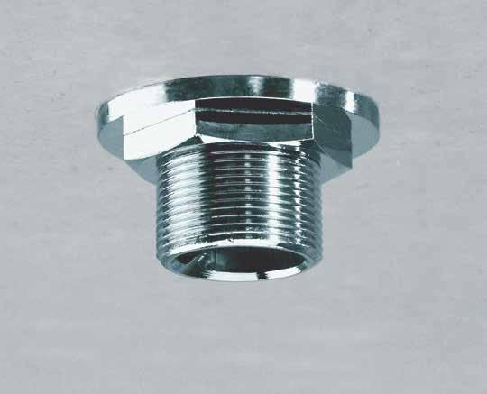
36 ST DRAIN FITTINGS TYPE ST-G: DRAIN FITTINGS WITH WIDE FUNNEL Special fittings to drain condensation from rectangular ductwork or other equipment. The duct wall is swaged to form a funnel-like drainage basin. A water-tight seal is created at the thread connection. Easy installation (just drill a hole and screw in the drain fitting). All parts are protected against corrosion. The duct wall is pressed tightly against the rim of the fitting to form a water-tight (*) seal as the duct is swaged. A large duct area is drawn into the funnel-like shape. Duct wall. The funnel is made of a sturdy 1/8 galvanized plate. Fittings, nuts and caps are all made of corrosion resistant chrome-plated brass. (*) Normally no sealant is required. Only when the surface of the duct is damaged or rough, mastic should be applied around the rim. INSTALLATION 1. Drill a hole in the duct wall. 2. Insert the fitting into the hole, slide on the funnel plate and tighten the nut until the duct wall is drawn into the funnel. 3. The cap is only necessary if no connection to a drain pipe is foreseen. ORDER RANGE ST-G Drain Fitting with Wide Funnel Catalog No. Description Material ST-G ½ ½ Drain with Wide Funnel Galv. steel / chrome-plated brass ST-G ¾ ¾ Drain with Wide Funnel Galv. steel / chrome-plated brass ST-G 1 1 Drain with Wide Funnel Galv. steel / chrome-plated brass ST-G 1 ½ 1 ½ Drain with Wide Funnel Galv. steel / chrome-plated brass Drain Fitting Caps (suitable for all drain fittings) Catalog No. Description Material STCAP- ½ Drain Fitting Cap Chrome-plated brass STCAP ¾ Drain Fitting Cap Chrome-plated brass STCAP 1 Drain Fitting Cap Chrome-plated brass STCAP 1 ½ Drain Fitting Cap Chrome-plated brass Bold = In stock 32
37 ST DRAIN FITTINGS TYPE ST-K: DRAIN FITTINGS WITH NARROW FUNNEL Special fittings to drain condensation from rectangular ductwork or other equipment. The duct wall is swaged to form a funnel-like drainage basin. A water-tight seal is created at the thread connection. Easy installation (just drill a hole and screw in the drain fitting). All parts are protected against corrosion. The duct wall is pressed tightly against the rim of the fitting to form a water-tight (*) seal as the duct is swaged. The duct wall ist drawn into a funnel-like shape. Duct wall. Fittings, nuts, funnels and caps are all made of corrosion resistant chrome-plated brass. (*) Normally no sealant is required. Only when the surface of the duct is damaged or rough, mastic should be applied around the rim. INSTALLATION 1. Drill a hole in the duct wall. 2. Insert the fitting into the hole, slide on the funnel plate and tighten the nut until the duct wall is drawn into the funnel. 3. The cap is only necessary if no connection to a drain pipe is foreseen. ORDER RANGE ST-K Drain Fittings with Narrow Funnel Catalog No. Description Material ST-K ½ ½ Drain Chrome-plated brass ST-K ¾ ¾ Drain Chrome-plated brass ST-K 1 1 Drain Chrome-plated brass ST-K 1½ 1½ Drain Chrome-plated brass Bold = In stock Drain Fitting Caps (suitable for all drain fittings) Catalog No. Description Material STCAP-½ Drain Fitting Cap Chrome-plated brass STCAP-¾ Drain Fitting Cap Chrome-plated brass STCAP-1 Drain Fitting Cap Chrome-plated brass STCAP-1½ Drain Fitting Cap Chrome-plated brass 33
.")
38 ST DRAIN FITTINGS TYPE ST-R: DRAIN FITTINGS FOR ROUND DUCTS Special fittings to drain condensation from round ductwork or other curved surfaces. The duct wall is swaged to form a funnel-like drainage basin. A water-tight seal is created at the thread connection. Easy installation (just drill a hole and screw in the drain fitting). All parts are protected against corrosion. The funnel is made of a sturdy 14 gauge galvanized plated. A large duct area is drawn into a funnel-like shape. Duct wall. The duct wall is pressed tightly against the rim of the fitting to form a watertight (*) seal as the duct is swaged. Fittings, nuts and caps are all made of corrosion resistant chrome-plated brass. (*) Normally no sealant is required. Only when the surface of the duct is damaged or rough, mastic should be applied around the rim. INSTALLATION 1. Drill a hole in the duct wall. 2. Insert the fitting into the hole, slide on the funnel plate and tighten the nut until the duct wall is drawn into the funnel. 3. The cap is only necessary if no connection to a drain pipe is foreseen. ORDER RANGE Please refer to next page 34
39 ST DRAIN FITTINGS TYPE ST-R: DRAIN FITTINGS FOR ROUND DUCTS ORDER RANGE ST-R Drain Fittings for Round Ducts Catalog No. Description for duct-ø Material ST-R ½ - 8 Drain Fitting with Galvanized Saddle 8 galv. steel / chrome-plated brass ST-R ¾ - 8 Drain Fitting with Galvanized Saddle 8 galv. steel / chrome-plated brass ST-R 1-8 Drain Fitting with Galvanized Saddle 8 galv. steel / chrome-plated brass ST-R ½ - 10 Drain Fitting with Galvanized Saddle 10 galv. steel / chrome-plated brass ST-R ¾ - 10 Drain Fitting with Galvanized Saddle 10 galv. steel / chrome-plated brass ST-R 1-10 Drain Fitting with Galvanized Saddle 10 galv. steel / chrome-plated brass ST-R ½ - 12 Drain Fitting with Galvanized Saddle 12 galv. steel / chrome-plated brass ST-R ¾ - 12 Drain Fitting with Galvanized Saddle 12 galv. steel / chrome-plated brass ST-R 1-12 Drain Fitting with Galvanized Saddle 12 galv. steel / chrome-plated brass ST-R ½ Drain Fitting with Galvanized Saddle galv. steel / chrome-plated brass ST-R ¾ Drain Fitting with Galvanized Saddle galv. steel / chrome-plated brass ST-R Drain Fitting with Galvanized Saddle galv. steel / chrome-plated brass ST-R ½ Drain Fitting with Galvanized Saddle galv. steel / chrome-plated brass ST-R ¾ Drain Fitting with Galvanized Saddle galv. steel / chrome-plated brass ST-R Drain Fitting with Galvanized Saddle galv. steel / chrome-plated brass ST-R ½ Drain Fitting with Galvanized Saddle galv. steel / chrome-plated brass ST-R ¾ Drain Fitting with Galvanized Saddle galv. steel / chrome-plated brass ST-R Drain Fitting with Galvanized Saddle galv. steel / chrome-plated brass ST-R ½ Drain Fitting with Galvanized Saddle galv. steel / chrome-plated brass ST-R ¾ Drain Fitting with Galvanized Saddle galv. steel / chrome-plated brass ST-R Drain Fitting with Galvanized Saddle galv. steel / chrome-plated brass ST-R ½ Drain Fitting with Galvanized Saddle galv. steel / chrome-plated brass ST-R ¾ Drain Fitting with Galvanized Saddle galv. steel / chrome-plated brass ST-R Drain Fitting with Galvanized Saddle galv. steel / chrome-plated brass Drain Fitting Caps (suitable for all drain fittings) Catalog No. Description for duct-ø Material STCAP-½ Drain Fitting Cap 8-40 chrome-plated brass STCAP-¾ Drain Fitting Cap 8-40 chrome-plated brass STCAP-1 Drain Fitting Cap 8-40 chrome-plated brass STCAP-1½ Drain Fitting Cap 8-40 chrome-plated brass NOTE: For duct-ø larger than 40, the drain fittings for flat duct walls ST-K and ST-G can be used. Bold = In stock METU-SYSTEM Catalog Drain Fittings - Rev


40 HANGERS & DUCT SUPPORTS III

41 AL SUPPORT BRACKETS For the suspension of rectangular ductwork and/or equipment using 3/8 threaded rod. Sturdy construction with loadbearing capacity up to 300 lbs. Large supporting surface area prevents the edge of the duct from being deformed. Easy installation. Duct wall. The large surface area prevents the edge of the duct from being deformed. The shape of the Support Bracket is designed to distribute the load on the threaded rod and to hold it tight against the duct wall in order to ensure that the nut provides the main support. Two rivets or self-tapping screws are used to secure the AL Support Bracket. The nut is partly under the edge of the duct and therefore supports the main load while reducing the strain on the threaded rod. DIMENSIONS AND LOAD-BEARING CAPACITY The AL Support Brackets have a height of 1-1/2 inches, a width of 2 and an overall depth of 1-1/2 inches (approximately). The load-bearing capacity is mainly limited to the strength of the ductwork, since the duct wall will buckle before the bracket deforms. With a duct wall thickness equal to 20 Gauge for instance the AL Support Bracket loading capacity is 300 pounds per bracket. The breaking load is three times higher. INSTALLATION Press the AL Support Bracket tight against the duct wall and drill through the 3/16 guide holes to accomodate rivets or install self-tapping screws. The threaded rod can be positioned either before or after the fixing of the Support Bracket on the duct wall. Sound isolation: If sound isolation is required, we recommend the use of SI Isolation Hangers. DESIGNATION Catalog No. Description for threaded rod Ø AL-3/8GA Galvanized AL Support Bracket 3/8 36
42 MB ANGLE BRACKETS Rugged 1/8 galvanized steel brackets. Used for the suspension of rectangular ductwork and equipment. Available in three different lengths to accomodate varying load requirements. The included Rubber Isolator provides good sound and vibration isolation. Threaded Rod 3/8 DIMENSIONS MB Angle Brackets (data in inches) 1 1-3/16 1-1/2 Ø 3/16 11/16 Ø 1/2 without rubber isolator (Ø 3/8 with rubber isolator Two-part Rubber Isolator with moulded-on washer provides good sound and vibration isolation. 2-1/8 2-1/8 2-1/8 Length of leg (values under Designation ) 1/2 1/8 DESIGNATION AND LOAD-BEARING CAPACITY SKU Catalog No. Isolated with Length of leg No. of holes Loading capacity F06V-1001 MB-3/8GA-4 Rubber Isolator lbs* F06V-1002 MB-3/8GA-6 Rubber Isolator lbs* F06V-1003 MB-3/8GA-8 Rubber Isolator lbs* * The indicated maximum load-bearing capacity is dependent upon use of #10 screws for fastening into minimum 22 gauge material for the 260 lb. rating, 20 gauge material for the 320 lb. rating and 18 gauge material for the 420 lb. rating. 37

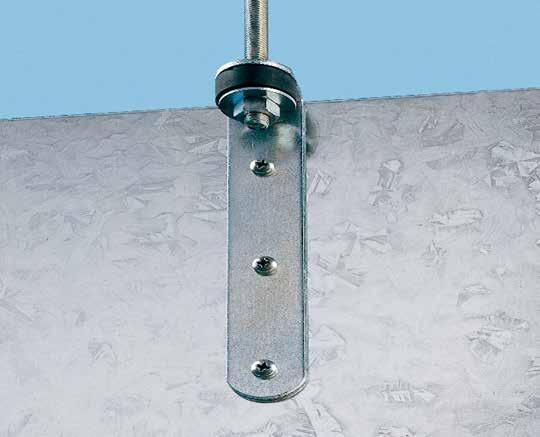
43 BA CIRCULAR DUCT SUPPORTS For the suspension of circular ductwork using 3/8 threaded rod. Standard 1 hanger strap encircles the duct. A press-formed steel bracket joins the two ends of the steel strap and provides a suspension point for the threaded rod. The steel strap is hand-formed into the bracket, requires no tools and is self-locking. High load-bearing capacity. Galvanized coiled strap or strips cut from waste material may be used. Heavy galvanized steel bracket for rigidity. At this point the fixture is secured by its own weight. GP Rubber Isolator with integrated metal washer. (only with BA3S and BA4S). INSTALLATION Both ends of the strap are bent over approximately 1-2 inches. Be sure to protect your hands with gloves! Hook the ends through the slots in the bracket. Suspend the assembly from a threaded rod DESIGNATION AND FIELD OF APPLICATION SKU Catalog No. Description F09A-1001 BA3-1-3/8GA Galvanized BA Support Bracket for 1 strap and 3/8 rod F09V-1004 BA3S-1-3/8GA Galvanized BA Support Bracket with Isolator for 1 strap and 3/8 rod F09A-1002 BA /8GA Galvanized BA Support Bracket for 1-1/2 strap and 3/8 rod F09V-1005 BA4S-1.5-3/8GA Galvanized BA Support Bracket with Isolator for 1-1/2 strap and 3/8 rod F09A-1003 BA5-2-3/8GA Galvanized BA Support Bracket with Isolator for 2 strap and 3/8 rod F09V-1006 BA5S-2-1/2GA Galvanized BA Support Bracket with Isolator for 2 strap and 1/2 rod *The indicated maximum load-bearing capacity has a breaking load of approximately three times higher. 38

44 SI ISOLATION HANGERS For the sound isolated suspension of ductwork and equipment using 1/4, 3/8 and 1/2 threaded rods. A rubber isolator is placed between two 12 gauge tension brackets eliminating the transmission of sound and vibrations. Available in three different sizes to accomodate varying load requirements. Built-in scale allows actual load to be read. The 12 gauge tension brackets have a much greater load-bearing capacity than the corresponding threaded rods. The load can be read-off this scale. The rubber isolator prevents vibrations from being transmitted. The dimension on the outside corresponds to a standard openended wrench. The open space corresponds to the width of common square nuts to prevent the nut from turning. LOAD-BEARING CAPACITY AND DIMENSIONS Type Loading capacity* Threaded rod Overall length max. width Rubber thickness SI-1/4 880 lbs 1/4 5-1/2 1-9/16 x 1-9/16 1-3/4 SI-3/ lbs 3/8 5-7/8 1-3/4 x 1-3/4 2 SI-1/ lbs 1/2 6-1/4 2 x 2 2-3/16 * Loading capacity is limited to rating of threaded rod being used. DESIGNATION SKU Catalog No. Description F02V-1001 SI-1/4 1/4 Isolator F02V-1002 SI-3/8 3/8 Isolator F02V-1003 SI-1/2 1/2 Isolator 39
45 CIRCULAR CONNECTORS IV

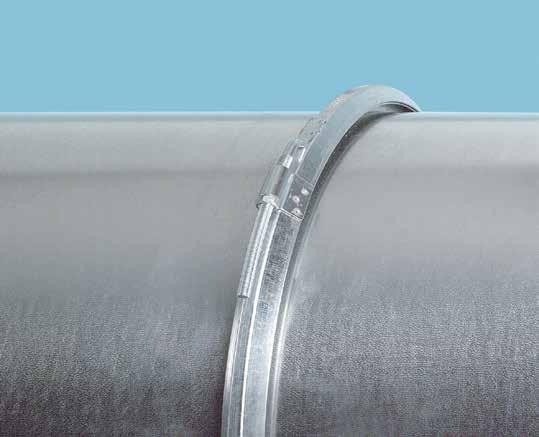
46 MF FLANGE SYSTEM Premier flange connection. 3-piece connection system with SR joining clips reduces installation costs. Suitable for both spiral seam and longitudinal seam ductwork. System design benefits for both positive and negative pressure systems. SR joining clips are used to assemble the ducts. For round ducts 8 to 118 in diameter. International Patents When tightening the SR Joining Clip two forces come into play: a radial force centering the flanges, and an axial force pushing the flanges against one another. Air-tightness is achieved through a mastic strip in which the end of the duct imbeds When SR Joining Clips with gasket are used, no gasket application on the flange face is necessary. This prevents the gasket from being damaged during installation and speeds up assembly. The flange is secured in the duct by either spot-welding, riveting or self-tapping screws As an alternative the mastic can be applied inside the duct between the circular flange and the duct wall. 40
47 MF FLANGE SYSTEM BENEFITS - Makes installation more efficient and reduces field labor costs - Enables lighter gage metal to be used for spiral pipe - Provides additional stiffness and rigidity to your duct system - Lets you use round pipe in conditions you couldn t before FEATURES One connection is made of: 2 MF Circular Flanges and 1 SR Joining Clip Suitable for: duct-ø Not suitable for: stiffening ribs spirally wound straight seam turned out edge fittings with turned out edge Dimensions: (galvanized version) A There are three MF Circular Flange profile sizes: MF 45 for duct-ø 8 18 MF 90 for duct-ø MF 160 for duct-ø B A B D C E C D E

48 MFH FLANGE SYSTEM Cost effective flange connection. Simple profile that provides additional duct reinforcement. Stiff sealing surfaces provide great surface for gaskets, reducing the need for external sealants. Suitable for both spiral seam and longitudinal seam duct work. Connection without the use of an SR joining clip. For round ducts 20 to 60 in diameter. Flange Stiff flange surfaces allow for easy gasket installation for sealing. Leg Pre-punched pilot hole facilitates self-drilling screw installation. 42
49 MFH FLANGE SYSTEM BENEFITS - Provides additional stiffness and rigidity to your duct system - Lets you use round pipe in conditions you couldn t before - Enables connection without the use of an SR joining clip FEATURES - Available in 18 gage galvanized steel - Assembled using #10 TEK screws - Pre-punched pilot holes in one layer of the hem aid in installation - This product is suitable for pipes ranging in diameter from 20 to 60 Dimensions: Two flange sizes available: MFH 45 for duct-ø MFH 160 for duct-ø Flange Height Leg Length Material Thickness

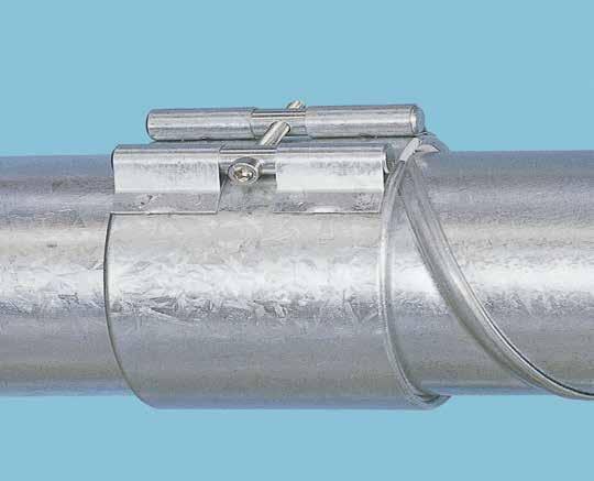
50 SR JOINING CLIPS Joining Clips enable the assembly of MF Circular Flanges. Allows considerable cost savings thanks to the one-bolt system. Available with and without gasket. For round duct 8 to 118 in diameter. SR-Shell SR-Curved Bolt The ends of the Joining Clip overlap and compress the selfadhesive gasket (only on Joining Clips with gasket) A SE Nut Runner fitted on a drill motor allows rapid tightening of the nut. 1 2 When tightening the SR Joining Clip two forces apply: 1. a radial force centering the flanges, and 2. an axial force pushing the flanges against one another. 44
51 SR JOINING CLIPS INSTRUCTIONS FOR JOINING (2) MF FLANGES 1 Only when SR Joining Clips without gasket are used, apply the gasket in the middle of the flange face as depicted on one of the mating flanges. The end of the gasket should butt up to the beginning. Gasket comes in three sizes to accomodate round diameters from 8-18, and and is available by the roll. 2 Take SR Joining Clip in your hand and back off nut until you are able to hang the SR Joining Clip over the flange. Note: Do not remove nut completely. 3 Insert the next duct section into the lower half of the SR Joining Clip. Continue to raise the opposite end of the duct joint until both flanges are parallel. If needed, METU- SYSTEM alignment grips can be used to assist in this alignment process, particularly handy in vertical duct runs. 4 Finally tighten the SR Joining Clip using the correctly sized SE Nut Runner fitted on a drill motor. Interrupt the tightening process several times and hammer the Joining Clip slightly with a rubber hammer to ensure a tight fit on the flanges. Please note the max. torque figures of the nut: SR 8-18 Galv.: 3-5 ft/lb Stainless: 5 ft/lb SR Galv.: 12 ft/lb Stainless: 14 ft/lb SR Galv.: 39 ft/lb Stainless: 45 ft/lb 5 BA Duct Hanger Brackets enable secure and economical duct hanging using a single 3/8 rod and 1 hanger strap. This product meets SMACNA standards for use on ducts up through 36 round when installed at a maximum of 12 spacing. This product is also available with and without sound isolation. 45

52 MU OVERCOLLAR Economical connection for small duct diameters. Great device for connecting to terminal units and exhaust air valves. No projections inside the duct. A one-bolt attachment system ensures a rapid and troublefree assembly. Can be easily disassembled. No preparation of the duct ends necessary. For duct diameters from 3 to 16 *. Standard gasket made of polyethylene foam. Other gaskets for special requirements are available upon request The rounded ends and the angled gasket facilitate the insertion of the duct. The gasket s elasticity completely seals even the external seam of spirally wound ductwork When the MU Overcollar is tightened, the two ends of the ducting are clamped metal against metal. (*) 14 and 16 Overcollars must only be used with heavy gauge duct systems as the tightening force of the Overcollar can cause the duct to collapse if the tightening torque is not closely adhered to. 46
53 MU OVERCOLLAR APPLICATIONS Suitable for: Duct-Ø Not suitable for: Spirally wound Straight seam Fittings 3 up to 16 * Turned out edge Fittings with turned out edge Stiffening ribs (*) 14 and 16 Overcollars must only be used with heavy gage duct systems as the tightening force of the Overcollar can cause the duct to collapse if the tightening torque is not closely adhered to. Stability: When the Overcollar is fully tightened, the ductwork is held rigid, both longitudinally as well as to impede deflection or bending. The tensile strength in the axial direction is very high. On a smooth duct wall of 4 duct-ø for instance, 250 lbs. are necessary to separate the ducts. The separation force required is much higher for larger diameter ductwork and spirally wound ductwork. This rigidity is a fundamental benefit when compared with simple push-in connectors. It simplifies the installtion of the ductwork while enabling considerable cost and time savings! Air-tightness: Overcollars provide a simple, leak-free* connection for round ducts. (*) There is a very small gap along one side of the duct seam on spirally wound ductwork which cannot be fully sealed by the gasket. To achieve higher air-tightness requirements just apply some mastic at this point along the seam. Drag and noise: Because the duct ends are embedded in the gasket there are no projections inside the duct which could hinder the air flow. Therefore noise and dirt accumulations are avoided. INSTALLATION INSTRUCTIONS Fitting the MU Overcollar is very simple: Push both duct sections inside the Overcollar making sure that a distance between 1/4 (min.) and 1 (max.) is left between the duct ends. The insertion depth should be approximately the same for each duct section. The Overcollar can be rotated before tightening the clamping bolt for esthetical or practical purposes. Tighten the clamping bolt forcefully using a drill motor, power screwdriver or hand socket wrench until the peened over ends of the Overcollar are tight to the duct, metal to metal. The overcollar edges should be embedded into the duct seams. Maximum torque: 4 ft/lbs 47

54 ACCESSORIES METU-SYSTEM E Catalog 2009 Rev. 00 V
55 DUCTSHIELD FOR THE PROTECTION OF DUCTWORK DURING STORAGE, TRANSPORT AND BUILDING CONSTRUCTION Works well on galvanized steel, stainless steel and aluminum. Withstands temperatures up to 140 F. Does not leave sticky residue on ductwork after removal. Available in three sizes, including extra wide 48. Environmentally friendly and fully recyclable! Illustration: DuctShield comes in prepackaged 2, 3 and 4 rolls to make the most effective use of the protective material. Contact local authorities for conditions or restrictions regarding proper disposal of PE film DuctShield is a high strength, full release, adhesive backed polyethylene film designed specifically for the HVAC Industry. Although it s uses are unlimited, its primary purpose is to protect the open ends of ductwork, fittings, and other HVAC products from hard to remove dirt and debris, which often accumulates prior to final installation DuctShield has been tested to withstand a variety of weather conditions, and will not blow off during transportation to the job site Tensile strength: > lb/in² (Additional technical specifications available upon request). For best results, duct surfaces should be clean and dry before application PRODUCT INFORMATION A full 3.2 mil in thickness, it outclasses the competition in gauge and strength, yet is still soft and easy to apply LIMITED PRODUCT WARRANTY METU-STREIMER warrants DuctShield to be free from defects in materials or workmanship, under normal use and service only at the time of shipment from our facility. If the material is shown to be defective at the time of shipment, METU-STREIMER will replace or issue credit for the original purchase price. This limited warranty supersedes and is in lieu of all other warranties or guarantees whether written or oral, express or implied, including, without limitation, warranties for merchantability and fitness for a particular purpose. Because of the possibility of surface variances, quality, structural movement or externally caused damage, METU-STREIMER shall not be liable for any consequential, special, incidental or other damage including, but not limited to, loss of profits or damage to any surface to which DuctShield is applied. This limited warranty cannot be amended, altered or modified in any way except in writing signed by an authorized officer of METU-STREIMER. No other person has any authority to bind METU-STREIMER with any representation or warranty whether oral or written. Catalog No. Name Description Unit Width Length Cartons PE G DuctShield Polyethylene Film 24 x 200 x.0032 x Green Rolls / Per PE G DuctShield Polyethylene Film 36 x 200 x.0032 x Green Rolls / Per PE G DuctShield Polyethylene Film 48 x 200 x.0032 x Green Rolls / Per METU-SYSTEM E Catalog 2009 Rev

56 SE NUT RUNNER For the tightening of the SR Joining Clip bolt in a few seconds. The hollow body of the SE Nut Runner provides sufficient clearance for the curved SR Joining Clip bolt. Suitable for all commonly used electric and pneumatic tools. The nut can be tightened continuously to the end of the thread. The body is made of galvanized steel to prevent corrosion. Different SE Nut Runners versions are available for a range of standard square drive socket sets. The body is hollow to accommodate the curved SR Joining Clip bolt. The radius is formed to the SR Joining Clip radius ranges. ROUND CONNECTOR ACCESSORIES ORDER RANGE SKU Catalog No. Description G0A3A-1002 SENTUTRUNNER-SM3/8 Nut Runner to Tighten SR Joining Clips Small 8-18 Round 3/8 Chuck G0A3A-1005 SENTUTRUNNER-MD3/8 Nut Runner to Tighten SR Joining Clips Medium Round 3/8 Chuck G0A3A-1008 SENTUTRUNNER-LG/38 Nut Runner to Tighten SR Joining Clips Large Round 3/8 Chuck METU-SYSTEM E Catalog 2009 Rev
WIDESPREAD LAVATORY MODELS WITH HI-ARC SPOUT
 5951, 5961, 5981, 5983, 5993 SERIES MT122B INSTALLATION INSTRUCTIONS THESE INSTRUCTIONS MUST BE LEFT WITH HOMEOWNER WIDESPREAD LAVATORY MODELS WITH HI-ARC TRADITIONAL CROSS NOTE: Handle Inserts are not
Spiral Duct. Contents. Introduction 1. Duct & Fitting Range 2. Duct Sizes 3. Fittings 5. Round Duct Connector 7. Installation 8
 Contents Introduction 1 Duct & Fitting Range 2 Duct Sizes 3 Fittings 5 Round Duct Connector 7 Installation 8 Celmec International Pty Ltd ACN 005 850 546 Melbourne Tel: +61 3 8552 8200 Fax: +61 3 9555
Installation instruction
 Installation instruction Ci51 116 FACTS Technical specifications Model i51 Log box (option) Output 6-11 kw Nominal output 8 kw Efficiency 80 % Weight (kg) 215 50 Powerstone (option): + 100 kg Width (mm)
Glass Door Fittings Glass Door Accessories
 Angled striking plate Aluminium stainless steel coloured 981.27.983 Recess striking plate DIN left DIN right Steel nickel plated matt 911.39.285 911.39.28 WC thumbturn cylinder Area of application: For
Door Bushing Replacement & Latch Adjustment Monaco Group Coaches
 Door Bushing Replacement & Latch Adjustment Monaco Group Coaches Contents Door Latch Adjustment & Repair... 1 Symptoms:... 1 Replacing the bushing VS. Adjusting the latch rods.... 1 How the bushing works....
I- 39. Liquidtight Connectors and Hubs for Liquidtight Flexible Metal Conduit General Information and special features.
 Liquidtight Connectors and Hubs for Liquidtight Flexible Metal Conduit General nformation and special features. - 39 Seal out oil, water, dirt, dust and fumes wherever liquidtight flexible metal conduit
Tank. Part B, Section 1. This section covers the following unit configurations. Pump Piston Pump (E or G)
") Part B, ection Model Voltage This section covers the following unit configurations. 3400V All Pump Piston Pump (E or G) Manifold Control 4-Port (A) Vista tandard (V) Vista Pattern (PC) Vista Temperature
Part B, ection Model Voltage This section covers the following unit configurations. 3400V All Pump Piston Pump (E or G) Manifold Control 4-Port (A) Vista tandard (V) Vista Pattern (PC) Vista Temperature
4-foot Economy Sign Post. 4-foot post is rated at 2 pounds per foot. 7-foot Economy Sign Post
 Introduction: ComplianceSigns.com offers a variety of sign posts, sign mounting hardware, sign bases, mounting tape and more to mount your safety signs indoors or out. We offer three styles of sign posts,
Section 11 Workstation Components
 1 Section Quick and easy access to parts is made possible by the wide variety of trays, bins, and framing components available from Bosch. Individual workstation grab trays, containers, and ledges place
TITAN Fuel Tanks. INSTALLATION INSTRUCTIONS G e n e r a t i o n V
 TITAN pt. no.: 02 0000 0128 Important: Please read these instructions carefully and completely before starting the installation. TITAN Fuel Tanks INSTALLATION INSTRUCTIONS G e n e r a t i o n V Extended
The Contractor s Choice / America s Choice Corporate: (800) Fax: (201)
 Fax: (201)") The Contractor s Choice / America s Choice Corporate: (800) 503-9805 Fax: (201) 964-9030 www.elgenmfg.com MISSION STATEMENT Striving to become the #1 single source solutions provider, serving sheet metal
The Contractor s Choice / America s Choice Corporate: (800) 503-9805 Fax: (201) 964-9030 www.elgenmfg.com MISSION STATEMENT Striving to become the #1 single source solutions provider, serving sheet metal
Wire and Cable Holders
 WIRE MANAGEMENT Wire and able Holders For low cost wire management. The push-mount style comes in vertical orientation for top entry and narrow width, and horizontal orientation for side entry and low
* * 4023 KR. Step 1 Prepare the Keyed Removable Unit. Not for use on electric or fire rated removable mullions
 condition. *64009-00* 64009-00 Keyed Removable Mullions 403 KR Installation Instructions Not for use on electric or fire rated removable mullions This kit includes the following parts: (Not to scale) 5/6
Tuf-Lite and Tuf-Lite II Fans 6000M Series Hub
 Tuf-Lite and Tuf-Lite II Fans 6000M Series Hub INSTALLATION MANUAL Adjustable Pitch Fan Assembly 32.8 or 10 Meter Diameter Hudson Tuf-Lite and Tuf-Lite II fan blades Hudson Tuf-Lite (black) fan blades
HANDWHEELS.
 HANDWHEELS 5 Handwheels Aluminum Angular Solid Handwheel...5.2 Aluminum Angular Spoked Handwheel... 5.2 Aluminum Finger Wheel... 5.10 Cast Angular Spoked Handwheel... 5.3 Cast Iron Angular Spoked Handwheel...
Product instruction manual Ream Cutting Systems RE3943, RE3946, RE3947, RE3971, RE3952E
 Product instruction manual Ream Cutting Systems RE3943, RE3946, RE3947, RE3971, RE3952E The Trimfast Ream Cutters are reliable, high performance cutters that will give you the results you need quickly
Model 205 Fireview Maintenance Kit
 Model 205 Fireview Maintenance Kit Please read all of the instructions before you begin the procedure. Confirm that you have all the necessary tools and parts required. Allow about one hour to complete
HANDLES, LE VERS & CR ANKS
 Handles, Levers & Cranks Plastic Pull/Lift Handle...112 Plastic Revolving Fold-Away Handle... 95 Plastic Revolving Heavy Duty Handle With Steel Shank... 92 Plastic Revolving Handle With Steel Through Shank...
Clay Adaptors & Insert Stove Kits
 Clay Adaptors & Insert Stove Kits September 2014 Tel: +353 46 95 58030 Fax: +353 46 95 58034 Email: sales@miflues.ie Web: www. miflues.ie INTRODUCTION CLAY ADAPTORS Mi-Flues Clay Adaptors are specially
RTA flexible conduits
 [ PROTETION OF LES ] Products and systems RT flexible conduits For each application and environmental stress there is a corresponding polyamide, PV or metal-plastic flexible conduit solution, ideal for
Tuf-Lite and Tuf-Lite II Fans 6000 Series Hub
 Tuf-Lite and Tuf-Lite II Fans 6000 Series Hub INSTALLATION MANUAL Adjustable Pitch Fan Assembly 32 and 33 Diameter Hudson Tuf-Lite and Tuf-Lite II fan blades Hudson Tuf-Lite (black) fan blades are made
SECTION I-1. Type: 1812-AC. Fuel: Air-Gas.
 RADIANT LINE BURNER. SECTION I-1. Type: 1812-AC. Manufactured from a heat resisting cast alloy with a ceramic front face, this radiant burner type is ideally suited for use in Infrared Heating production
Installation Instructions
 THE COLLECTION by Installation Instructions 0 BIDET FITTING Thank you for selecting American-Standard...the benchmark of fine quality for over 00 years. To ensure that your installation proceeds smoothly--please
INSTALLATION GUIDE INTRODUCTION
 INSTALLATION GUIDE for for HotEdge Rail Rail INTRODUCTION HotEdge Rail is a patent pending one-piece roof edge ice melt systems engineered to easily install on standing seam, pro panel, and corrugated
DOOR - Single Leaf, Premium Duty, Quick-Acting Model 1430 Features 1
 DOOR - Single Leaf, Premium Duty, Quick-Acting Model Features 1 FREEMAN MARINE Quick-Acting doors feature patented chain-drive, single actuation dogging. This design feature allows for quick-acting doors
INSTALLATION INSTRUCTIONS
 INSTALLATION INSTRUCTIONS KR54, KR1654, & KR4954 Keyed Removable Mullion NOT FOR USE ON ELECTRIC OR FIRE RATED MULLIONS. This kit includes the following parts: (Not to scale) WARNING Remove key, reinstall,
Amphenol RF Interconnects TNC 31 Series Threaded Lock RF Connector System Materials
 TNC 31 Series Threaded Lock RF Connector System Materials Body/Finish Contacts Centre MALE Centre FEMALE Insulator Gasket Crimp Ferrules* *Metal finishes Durability Brass/Nickel Brass/Gold Plated (Au)
Advantage Plus TIM-3600 Series Reel
 Read the following precautions and instructions before you begin assembly or using. Failure to comply with these instructions could result in personal injury or property damage. Keep these instructions
American Classic Rear Terrain Hub Bearing Change, Cassette Body Swap and Overhaul Instructions.
 12 x 142mm Thru Axle Retrofit Page 1 IDENTIFY YOUR TERRAIN HUB To identify, see the non-drive side of the hub (side without the cassette). Terrain hubs are in Terrain, Terrain Tubeless, and TCX Trekking
Installation instruction
 Installation instruction C 35T-Low www.contura.eu 82 CERTIFICATE PERFORMANCE DECLARATION No. C35TL-CPR-130618-SE-1 PRODUCT Product type Type designation Manufacturing number Intended area of use Fuel Stove
Urea/Adblue Hose Reel
 www.scintex.com.au sales@scintex.com.au Model: SHR3408 Urea/Adblue Hose Reel Product Manual Specifications Spring driven drum: for automatic rewind. Locking ratchet: to maintain the desired length of hose
Cassette-folding arm-awning markilux 990
 Cassette-folding arm-awning markilux 990 Mounting instructions 1. Overview 1 Projection profile 2 Folding arm 3 Fabric 4 Console 5 Cassette 6 Covering cap 7 Wall bracket 2. Mounting brackets 2.1 Overview
Contents. Introduction...3 Description...3. Pack Contents...4. Rada Heavy Duty EV Shower Fittings Right Angled Connector (RAC)...
...") SHOWER FITTINGS PRODUCT MANUAL IMPORTANT Installer: This manual is the property of the customer and must be retained with the product for maintenance and operational purposes. Contents Introduction...3
SHOWER FITTINGS PRODUCT MANUAL IMPORTANT Installer: This manual is the property of the customer and must be retained with the product for maintenance and operational purposes. Contents Introduction...3
PINS & BUSHINGS INCH
 www.danly.com TRUSTED SOLUTIONS AND INNOVATION PINS & BUSHINGS INCH Steel, Bronze & Self-Lubricating Friction & Ball Bearing Components www.danly.com PINS & BUSHINGS INCH Strategically located to serve
IB 7/40 Classic. Automatic residual ice discharge. Outstanding mobility. Efficient airflow in the device. Clear display
 IB 7/40 Classic Thanks to airflow optimisations, our Ice Blaster IB 7/40 impresses with excellent results during dry ice cleaning, even when working with low air pressures. Compact device. 1 Automatic
CONVEX Awning Instructions
 CONVEX Awning Instructions IMPORTANT NOTE: Please take a few minutes to become familiar with this entire document BEFORE beginning your installation. The time you spend doing this is well spent and will
P3000 UNIVERSAL Clamp-On
 IHI INSTRUCTION MANUAL Required Tools P3000 UNIVERSAL Clamp-On Wrench Allen Key P3001 65 ENDCAPS P3011 65 BLACK P300 7 ENDCAPS P301 7 WHITE P3003 ENDCAPS P3013 SILVER PART# DESCRIPTION ENDCAPS SIDE SUPPORTS
The safe & affordable install
 QSLG1000 Quick-Sling SPECS QSLG1000 Each arm attaches to wood using 2 zip screws for stability & a 4 through bolt & wing nut for security. Installs to steel using steel beam adapters. 28 points of anti-vibration
WALLCOVERING TOOLS MORE ON PAGES 22-23
 Producing high quality work is easy when you use the Paste-mate from Advance Equipment. 62 in. & 40 in. heavy duty paste machines the name in paste machines Manual, gear driven pasting machine for heavier
markilux 780 / 880 Remarkably compact yet strong conservatory awnings for small glass areas both on the interior and the exterior
 VERTICAL BLINDS AND CONSERVATORY AWNINGS safe timeless beautiful markilux 780 / 880 Remarkably compact yet strong conservatory awnings for small glass areas both on the interior and the exterior rated
Thermostatic Griddle Field Service Kit Instructions
 Thermostatic Griddle Field Service Kit Instructions The following document provides instructions on how to install a Garland Thermostatic Griddle Field Kit and is applicable to each 2 section of a Garland
RAFTER VI. Installation and Operation CAREFREE WITH AUTOMATIC AWNING SUPPORT. RV Accessory PRODUCT OVERVIEW
 CAREFREE RAFTER VI RV Accessory WITH AUTOMATIC AWNING SUPPORT Installation and Operation PRODUCT OVERVIEW The gives the awning user the ability to easily tighten the center fabric when the awning is extended.
PARTS LIST COLT COLT HEPA
 PARTS LIST COLT 800-1250 - 1450 COLT HEPA - 1250-1450 MOTOR / LID ITEM PART NO. PART DESCRIPTION QTY. 101 0891201 TOP COVER 1 102 0294341 TOP MOTOR SEAL 1 103 0299861 STRAIN RELIEF CORD CLAMP 1 104 0891131
Table Legs & Extensions 7.1
 .0 Table Legs & Extensions.1 Installation example: With end frame and bracket ( 633.13.200) With visible lifting column With concealed/invisible lifting column Installation example: With two brackets (
Reverse Osmosis system 50 GPD Instruction manual EN
 Reverse Osmosis system 50 GPD Instruction manual EN Contents 1. Unpacking 2. Scope of supply 3. Insertion of the membranes 4. Connecting the lines 5. Installation 6. First commissioning 7. Consumables
Thomas Scientific Swedesboro, NJ U.S.A.
 Thomas Scientific Swedesboro, NJ 08085-0099 U.S.A. Wiley Laboratory Mill, Model 4 3375-E10 (115 V, 50/60 HZ) USE AND CARE OF CATALOG NUMBER: 3375-E10 Wiley Laboratory Mill, Model 4 (115 V, 50/60 HZ) UNPACKING
* * KR54-F, KR9854 & KR9954 Installation Instructions. Read All Warnings Before Starting Installation! Index:
 *941061-00* 941061-00 Keyed Removable Mullion KR54-F, KR9854 & KR9954 Installation Instructions CLASSIFIED CLASSIFIED C Read All Warnings Before Starting Installation! Index: General Information ----------------
S E L E C T I O N. Abdominal Crunch. User manual
 and S E L E C T I O N T H E S T R E N G T H E V O L U T I O N User manual and and The identification plate of the and manufacturer, affixed along side the seat on the frame of the weight stack, gives the
Tarp Return. Questions? Contact Customer Or Parts Diagrams see Parts and Diagrams section on web at
 Roll Rite, LLC and its entire staff would like to not only Thank You but congratulate you on your purchase of one of what we feel to be the finest line of tarping systems in the industry. Tarp Return RR
VALORE SEVEN. Serial Number. Pacific) Version No.:V
 Version No.:V") VALORE SEVEN Version No.:V.206222 Serial Number Pacific) 7 9 8 " 5 8 " " 7 2 8 " 26 2 " 7 8 " 9" 2 8 " 2 8 " (H) 26.9" x (W) 8.26" x (D) 8.85" Hand shower hose: 59.05" Weight: Net: 0 lbs /Gross: 2 lbs
VALORE SEVEN Version No.:V.206222 Serial Number Pacific) 7 9 8 " 5 8 " " 7 2 8 " 26 2 " 7 8 " 9" 2 8 " 2 8 " (H) 26.9" x (W) 8.26" x (D) 8.85" Hand shower hose: 59.05" Weight: Net: 0 lbs /Gross: 2 lbs
Installation Guide. Single-Control Kitchen Sink Faucets
 Installation Guide Single-Control Kitchen Sink Faucets K-6352 K-6353 M product numbers are for Mexico (i.e. K-12345M) Los números de productos seguidos de M corresponden a México (Ej. K-12345M) Français,
CROSS HANDLE 5-HOLE BATH SET & PULL-OUT BLACK HAND SHOWER WITH DECK DIVERTER TRIM ONLY, TO SUIT R ROUGH M1-2202
 INSTALLATION INSTRUCTIONS M-00 CROSS HANDLE -HOLE BATH SET & PULL-OUT BLACK HAND SHOWER WITH DECK DIVERTER TRIM ONLY, TO SUIT R-00 ROUGH M-0 LEVER -HOLE BATH SET & PULL-OUT BLACK HAND SHOWER WITH CROSS
Tuf-Lite III Fans 4000KW Series Hub
 Tuf-Lite III Fans 4000KW Series Hub INSTALLATION MANUAL Hudson Tuf-Lite III fan blades Adjustable Pitch Fan Assembly 11 through 20 Diameter Hudson Tuf-Lite III fan blades are of single piece fiberglass
ELECTRA MAGIC RV and Marine Recirculating Toilets
 ELECTRA MAGIC RV and Marine Recirculating Toilets Because We Take Your Leisure Seriously Electrical Hookup RV and Marine Models Connect your 12-Volt or 24-Volt model Electra Magic directly to the appropriate
Tuf-Lite II Fans 7000 Series Hub
 Tuf-Lite II Fans Series Hub INSTALLATION MANUAL Hudson Tuf-Lite II fan blades Adjustable Pitch Fan Assembly 34 & 3 Diameter Hudson Tuf-Lite II (white, prev. blue***) fan blades are made from fiberglass
Perrin & Rowe Kitchen ROHL Pull-Out/Pull-Down COLORS/FINISHES. Polished Chrome Polished Nickel Satin Nickel English Bronze Inca Brass* 9 1/4
 PERRIN & ROWE TRADITIONAL PULL-DOWN FAUCET Perrin & Rowe Kitchen ROHL Pull-Out/Pull-Down U.4744 FEATURES Brass construction Metal lever CNC machined Dual spray with lock in modes 1 3/4 max installation
get connected with Bradford fittings & valves Bradford Company, Inc
 get connected with Bradford fittings & valves Bradford Company, Inc. 800.789.1718 www.bradfordfittings.com Bradford your top quality, sanitary stainless steel fittings & valves manufacturer serving you
2016 PRODUCTS & PRICES
 2016 PRODUCTS & PRICES LENGTH STOPS THAT ARE USER FRIENDLY Orders 1-800-821-3491 Phone 1-717-484-0230 Fax 1-717-484-0933 E-mail mayaposi@att.net Web mayaposi-stop.com MAYA POSITIONING EQUIPMENT MFG CO.
TRUSTED SOLUTIONS AND INNOVATION PINS & BUSHINGS INCH
 www.danly.com TRUSTED SOLUTIONS AND INNOVATION PINS & BUSHINGS INCH www.danly.com PINS & BUSHINGS INCH Service We Deliver and Quality You Can Depend On DANLY IEM is a leading manufacturer of die sets and
style vision & quarter turns quarter turns section section INDUSTRIAL, VEHICULAR & SPECIALTY SYSTEMS
 quarter turns vision & style quarter turns INDUSTRIAL, VEHICULAR & SPECIALTY SYSTEMS WE RE CHANGING THE FUTURE EBERHARD INDUSTRIAL, VEHICULAR & SPECIALTY SYSTEMS 3 quarter turns No. 626-PK Patent Pending
KAWNEER 1786 RIM EXIT DEVICE
 FEBRUARY, 2015 1 DOOR STILE Device C L 40" 41-9/32" Cylinder C L Bottom of door RIM EXIT DEVICE LOCATION DOGGING KEY EXIT DEVICE FILLER PLATE CYLINDER & CYLINDER RING HOUSING COVER CYLINDER INSTALLATION
IMPORTANT OWNER-OPERATOR INSTALLATION INSTRUCTIONS C2204A
 IMPORTANT OWNER-OPERATOR INSTALLATION INSTRUCTIONS C2204A Warnings Truck Bed and Camper Protection Torklift does not recommend installing your camper on top of a plastic bed liner (or other compressible
INSTALLATION INSTRUCTIONS TOWNSEND
 INSTALLATION INSTRUCTIONS TOWNSEND.00 DECK MOUNT BATH FILLER.0 Thank you for selecting American Standard... the benchmark of fine quality for over 00 years. To ensure that your installation proceeds smoothly-please
Arsen FAN COIL HOSES WITH BRAIDING AND WITHOUT BRAIDING EN ISO PRODUCED AND TESTED ISO 9001:2008 OHSAS 18001
 QUALITY MANAGEMENT SYSTEM CERTIFIED HEALTH & SAFETY MANAGEMENT SYSTEM Arsen FAN COIL HOSES WITH BRAIDING AND WITHOUT BRAIDING ISO 9001:2008 REGISTERED COMPANY EN ISO 10380 PRODUCED AND TESTED OHSAS 18001
GoBidet Bidet Attachment
 GoBidet Bidet Attachment 151 Ruths Place #5 Sequim, WA 98382 Tel 1-800-681-0753 Fax +1 360-681-4029 www.go-bidet.com MODEL #2003C In this box: 1 User Manual 1 GoBidet Unit w/ mounting bracket, nut, rubber
Couplings for Gates Hoses 7 Combination Nipple
 Supersedes 1 Long Shank Couplings for Gates Hoses 7 Combination Nipple Description: Cast brass, serrated shank, set has hex male and hex swivel female couplings, with a washer seal. Threads are GHT or
IB 15/120. Nozzle case holder. Automatic residual ice discharge. Glass-fibre reinforced plastic dry ice container. Outstanding mobility
 IB 15/120 The Ice Blaster IB 15/120 is one of the most powerful dry ice blasting machines on the market. It impresses with its robustness, highly reliable technology and the best results in dry ice cleaning.
 4567890123456789012345678901212345678901234567890123456789012123456789012345678901234567890121234567890123456789012345678901212345678901 23456789012345678901234567890121234567890123456789012345678901212345678901234567890123456789012123456789012345678901234567890121234567890123
IMPORTANT OWNER-OPERATOR INSTALLATION INSTRUCTIONS. Part # A7006
 IMPORTANT OWNER-OPERATOR INSTALLATION INSTRUCTIONS Part # A7006 Parts List Wobble Stopper Body Wobble Stopper Shaft Camper Bracket Lower Bracket Assembly Upper Bracket Upper Bracket Clamp 3/8 SAE Flat
Operation, Cleaning & Maintenance. For Aluminium Secondary
 , Cleaning & Maintenance For Aluminium Secondary Contents Horizontal Sliders 3 Vertical Sliders - Non-Balanced 4 Vertical Sliders - Balanced 5 Vertical Sliders - Tilt Back 6-7 Lift Outs 8 Hinged Units
Section B 5 Parts. 1. Introduction. Using the Illustrated Parts List. Parts B 5-1
 Parts B - Section B Parts. Introduction To order parts, call the Nordson Customer Service Center or your local Nordson representative. Use the parts list, and the accompanying illustration, to describe
/ Tool and Equipment Safety Tether System (T.E.S.T.S)
") 20 INSTRUCTIONS FOR USE AND PRODUCT GUIDE 799953 / 799955 Tool and Equipment Safety Tether System (T.E.S.T.S) Part # T353012 Rev 2 Reliance Industries LLC 2802 East X Street Deer Park, Texas 77536 281-930-800
20 INSTRUCTIONS FOR USE AND PRODUCT GUIDE 799953 / 799955 Tool and Equipment Safety Tether System (T.E.S.T.S) Part # T353012 Rev 2 Reliance Industries LLC 2802 East X Street Deer Park, Texas 77536 281-930-800
Retractable Hose Reel
 Retractable Hose Reel installation and Operation Please read before use We recommend keeping these instructions for future reference Hose Reel must be mounted before use Keep the hose retracted when not
ASSEMBLY GUIDE. Customer Service: INCH² 2-BURNER & 864 INCH² 2-BURNER
 ASSEMBLY GUIDE 688 INCH² 2-BURNER & 864 INCH² 2-BURNER DANGER If you smell gas: 1. Shut off gas to the appliance. 2. Extinguish any open flames. 3. Open lid. 4. If odor continues, keep away from the appliance
Therme storage water heater. Table of contents. Symbols used. Symbols used Symbol indicates a possible hazard. Installation instructions
 Therme storage water heater Table of contents Symbols used... 8 Installation instructions Water supply... 9 Choice of location... 9 Installation of the Therme... 9 Fitting the draining and venting valve...
PROFILE SYSTEM HANDLES, LOCKS, STOPS HANDLE, LOCKS, STOPS 108 MINITEC PROFILE SYSTEM
 PROFILE SYSTEM HANDLES, LOCKS, STOPS s pot S, s k c ol, s e l dnah HANDLE, LOCKS, STOPS 108 MINITEC PROFILE SYSTEM HANDLE AL Part. N 21.1138/0 - Aluminium, natural anodized - Weight 0,050 kg - Show cases
Stainless Steel Combined Drinking Fountain With Bottle Filler
 Stainless Steel Combined Drinking Fountain With Bottle Filler Product Code WH-DFBF-WRAS Stainless steel wall mounted drinking fountain with bottle filler spout. WRAS approved drinking water bubbler (tap)
CABLE CUTTING, STRIPPING AND CRIMPING TOOLS
 Cutting 38-39 Stripping 39 0 - CBE CUTTING, STRIPPING ND CRIMPING TOOS Ergonomic handles Surface protection High precision Flexibility With ergonomic handles and a specially The pliers are made of excellent
Installation and Maintenance Manual
 Freestanding Gas Stove MODEL: PGS2005 GPEBB20R GPEBW20R Installation and Maintenance Manual Warning Maintenance products should be carried out by professional and technical personnel with relevant qualification,
Southco 64 Push-to-Close Latch Visible, Locking, Slide Bolt
 Southco 64 Push-to-Close Latch, Locking, Slide olt 139.7 (5.50) 10.2 (.40) 108 (4.25) 4X Ø H RIVET LTCHES ONLY 22.6 (.89) Push-to-Close Latches 1.2 (.05) 45.1 (1.78) NON-LOCKING LOCKING* 23.4 (.92) TYPE
42-YP Series. Serie 42-YP Série 42-YP. Single Control Lavatory Faucet Grifo Monomando para el Baño Mitigeur de Robinet pour Lavabo
 42-YP Series Serie 42-YP Série 42-YP Single Control Lavatory Faucet Grifo Monomando para el Baño Mitigeur de Robinet pour Lavabo 07-28-05 EO6852C 30022-0100 Copyright 2005, Price Pfi ster, Inc. A COMPANY
INSTALLATION INSTRUCTIONS AND OWNER'S MANUAL AWNINGS. For trailers & motor homes with straight sides TOOLS REQUIRED
 AWNINGS INSTALLATION INSTRUCTIONS AND OWNER'S MANUAL For trailers & motor homes with straight sides TOOLS REQUIRED 1/4" electric drill Ratchet handle kit 3/8" & 7/16" socket No. 1 and No. 2 screwdriver
Section B 5 Parts. 1. Introduction. Using the Illustrated Parts List. Parts B 5-1
 Parts B - Section B Parts. Introduction To order parts, call the Nordson Customer Service Center or your local Nordson representative. Use the parts list, and the accompanying illustration, to describe
Tuf-Lite II Fans 8000 Series Hub
 Tuf-Lite II Fans 8000 Series Hub INSTALLATION MANUAL Hudson Tuf-Lite II fan blades Adjustable Pitch Fan Assembly 34 through 40 Diameter Hudson Tuf-Lite II (white, prev. blue**) fan blades are made from
NEWMAR SERVICE SCHOOL
 NEWMAR SERVICE SCHOOL TRAINING INFORMATION GUIDELINE FOR FEBRUARY 2013 OUR PRODUCTS: NOVA DUAL PITCH AWNING G-2000/ G-1500 2 P a g e G-2085 G-5000 3 P a g e G-LINKS 4 P a g e NOVA/ G-2000/ G-1500 BASIC
LITE Spear Awning Instructions
 LITE Spear Awning Instructions IMPORTANT NOTE: Please take a few minutes to become familiar with this entire document BEFORE beginning your installation. The time you spend doing this is well spent and
Page: HRSO-1
 PROJECT: LOCATION: ARCHITECT: ENGINEER: SALES ENGINEER: DATE: www.fumeavent.com info@fumeavent.com 866-794-1000 Page: HRSO-1 SPRING RETRACTABLE HOSE REEL SPECIFICATION SERIES HRS The vehicle exhaust extraction
Training Manual. Hand Rope Pump, P Model. Module 1: Production
 Training Manual PI-Model Rope Pump, Module 1, Production Training Manual Hand Rope Pump, P Model Module 1: Production June 2006, Chibombo, Zambia July 2006, Chimoio, Mozambique Arrakis September 2006 Arrakis
1946 READ AND SAVE THESE INSTRUCTIONS!
 EasyAwn Installation, Care and Maintenance Manual EasyAwn Quality, Since 1946 EasyAwn, LLC Toll Free: 877-EasyAwn http://www.easyawn.com READ AND SAVE THESE INSTRUCTIONS! EasyAwn Quarter Round Awning Installation
BROEN UNIFLEX FITTINGS FOR WATER BROEN UNIFLEX TM FITTINGS FOR WATER
 BROEN UNIFLEX FITTINGS FOR WATER TABLE OF CONTENTS Content Page Table of Contents 2 BROEN UniFlex TM BASIC 4 Product Overview 5 Water Fittings Bench Mounted Fitting with Swivel Spout... 6 Single Handle
Integrated Process Solutions
 Integrated Process Solutions w w w. m k s i n s t. c o m Series 31 ISO-KF fittings Sizes to 0 ( to 4'') Series 31 is a line of ISO-KF standard vacuum components. The ISO-KF system refers to the family
READ AND SAVE THESE INSTRUCTIONS! EasyAwn Spear Awning Installation
 EasyAwn Installation, Care and Maintenance Manual EasyAwn Quality, Since 1946 EasyAwn, LLC Toll Free: 877-EasyAwn http://www.easyawn.com READ AND SAVE THESE INSTRUCTIONS! EasyAwn Spear Awning Installation
Standard Awning Installation Instructions
 Standard Awning Installation Instructions Important Note: Please become familiar with this entire document BEFORE beginning your installation. The time you spend doing this is well spent and will make
4A1-114/114KR & 4A1-2 MANUAL TENSIONERS
 M L. C O O N AL TO 4A1-114/114KR & 4A1-2 W W W.T R AD IT IO MANUAL TENSIONERS READ THESE INSTRUCTIONS CAREFULLY. FAILURE TO FOLLOW THESE INSTRUCTIONS CAN RESULT IN SEVERE PERSONAL INJURY. GENERAL SAFETY
The Groomers Scissor Guide
 The Groomers Scissor Guide Anatomy of A Scissor Finger rest Scissors have multiple finger rests, removable finger rests or none at all. Finger inserts Some scissors come without, while others come with
Hammer, Discus, Shot Put, Javelin
 Hammer, Discus, Shot Put, Javelin Competition Aluminium Discus And Hammer Cage 7/10 M Order No. 30290 Order No. 30290 D (Double Net) Order No. 30290 DS (Dismantle to fit a 20 container) Competition aluminium
Closet and Specialty Hardware
 Closet and Specialty Hardware Door & Mirror Hardware...100 Magnetic and Bullet Catches... 100 Sliding Door Pulls........................................ 100 Mirror Clips/Glass Clips, Fittings and Latches...
I N ST R UC T I ON MODELS 1612E, 1712E & 1712RE SLICERS. FORM Rev. B (10-97) 1712RE 701 S. RIDGE AVENUE TROY, OHIO 45374
 1712RE 701 S. RIDGE AVENUE TROY, OHIO 45374") I N ST R UC 1712E T I ON MODELS 1612E, 1712E & 1712RE SLICERS S ML-104546 ML-104547 ML-104548 1612E 1712E 1712RE 701 S. RIDGE AVENUE TROY, OHIO 45374 FORM 19238 Rev. B (10-97) TABLE OF CONTENTS GENERAL......................................................................
I N ST R UC 1712E T I ON MODELS 1612E, 1712E & 1712RE SLICERS S ML-104546 ML-104547 ML-104548 1612E 1712E 1712RE 701 S. RIDGE AVENUE TROY, OHIO 45374 FORM 19238 Rev. B (10-97) TABLE OF CONTENTS GENERAL......................................................................
Hose Reel Series L701/G701
 Hose Reel Series L70/G70.0 WARNING: Read carefully and understand all INSTRUCTIONS before operating. Failure to follow the safety rules and other basic safety precautions may result in serious personal
Parts Catalog T7/T71/T73 M40000/M40001/M40003
 T7/T71/T73 M40000/M40001/M40003 REPAIR PARTS CATALOG NO. For machines starting with Serial No. T10001 ISSUED August 2010 ORDERS Please use Part Numbers when ordering and include the machine Serial Number