UNION STATION ACCESS AND CAPACITY IMPROVEMENT STUDY PROJECT REPORT
|
|
|
- Stewart Clark
- 6 years ago
- Views:
Transcription

1 UNION STATION ACCESS AND CAPACITY IMPROVEMENT STUDY PROJECT REPORT Washington Metropolitan Area Transit Authority Department of Planning and Joint Development In Association with District of Columbia Department of Transportation February 18, 2011
2 Table of Contents Executive Summary... 5 Union Station Introduction Study Overview Study Purpose...11 Scope and Methodology...13 Union Station Metrorail Station North Mezzanine...17 Present Demand and Performance Present Demand...19 Present Performance...20 Future Demand Future Rail Operating Plan and Implications...26 Proposed Access and Capacity Improvements Partial Build Scenario...28 Full Build Scenario...38 Conceptual Cost Estimate...42 Assessment of Future Station Performance Metrorail Mezzanine...43 Amtrak Concourse Approach...44 Metrorail Platform...46 Other Project Impacts Conclusion Appendices Appendix 1 Union Station Metrorail Ridership Characteristics...53 Appendix North Mezzanine Performance...54 Appendix 3 - Alternative Design Concept for the North Mezzanine...55 Appendix 4 - Performance of Alternative Design Concept...58 Appendix 5 - Design Drawings for the Full Build Scenario P a g e
3 Table of Figures Figure 1: Union Station and Associated Transportation Services...12 Figure 2: Existing Conditions North Mezzanine...15 Figure 3: Historical Ridership Growth at Union Station...16 Figure 4: Percentage Distribution of Hourly Volume at Metrorail Station...17 Figure 5: Study Zones at North Mezzanine of Metrorail Station (Union Station)...18 Figure 6: Performance of Metrorail Mezzanine...21 Figure 7: Performance of Amtrak Concourse Approach...22 Figure 8: Performance of Metrorail Platform...23 Figure 9: Location of Burnham Development...25 Figure 10: First Street NE Station Entrance...29 Figure 11: Relocated First Street NE Station Entrance...29 Figure 12: Proposed Partial Build Mezzanine Improvements...31 Figure 13: Proposed Partial Build Concourse Improvements...32 Figure 14: Proposed Partial Build H Street Passageway Entrance at H Street Tunnel...35 Figure 15: Proposed Partial Build H Street Passageway Entrance at H Street...36 Figure 16: Cross Section Through Passageway Tunnel Looking East...37 Figure 17: Garage Platform at H Street...37 Figure 18: Passageway Elevators at H Street...38 Figure 19: Proposed Full Build Mezzanine Improvements...40 Figure 20: Proposed Full Build Platform Concourse Improvements...41 Figure 21: Performance of Mezzanine...44 Figure 22: Performance of Amtrak Concourse Approach...45 Figure 23: Performance of Amtrak Concourse Approach...46 Figure 24: Alternative North Mezzanine Improvements...56 Figure 25: Alternative Amtrak Concourse Improvements...57 Figure 26: Performance of North Mezzanine...58 Figure 27: Performance of Amtrak Concourse Approach P a g e
4 Table of Tables Table 1: Annual Station Boardings (in thousands)...16 Table 2: 2009 Pedestrian Traffic within the North Mezzanine...19 Table 3: 2009 Average Travel Time for Metrorail Passengers...24 Table 4: 2009 Escalator Average Clearance Time (Peak Hour)...24 Table 5: 2030 Pedestrian Traffic within the North Mezzanine...27 Table 6: Summary of Conceptual Cost Estimates for Full Build...42 Table 7: Travel Time Saving Per Person (seconds)...47 Table 8: 2030 Average Escalator Clearance Time (Peak Hour)...47 Table 9: Comparison of Partial Build and Full Build Table 10: Comparison of Full and Alternative Build Scenarios P a g e
5 Executive Summary Union Station is the largest intermodal transportation center in the Washington metropolitan region, hosting Metrorail, Amtrak, commuter rail from Maryland and Virginia, intercity and local bus services and other transportation modes. The Metrorail station at Union Station is the busiest station in the Metrorail system and serves the commute and leisure travel needs of thousands of residents and visitors from DC, Virginia, Maryland and the entire East Coast. Built in the 1970s, this Metrorail station is reaching capacity and passengers experience crowding throughout the station on a daily basis. As travel demand at Union Station continues to grow from increased regional and local transit services, expanded intercity travel and the renewal of adjoining DC neighborhoods, enhancements to the Metrorail station are urgently needed, not only to relieve today s congestion but also to accommodate passenger growth in the years to come. The Washington Metropolitan Area Transit Authority ( Metro ) undertook the Union Station Access and Capacity Improvement Study in partnership with the District of Columbia Department of Transportation (DDOT) and Union Station stakeholders. This study focused on the north mezzanine of the Metrorail station, where passengers experience serious congestion in the peak hours and large-scale development is planned for the areas to the north. The purpose of the study was to define improvements that would increase the station s capacity and accessibility and move passengers quickly and safely. It also recognized that reducing crowding and delay would enhance customers experience and make public transportation pleasant and convenient. This study applied innovative techniques in the identification of existing station conditions and development of capacity expansion alternatives. Metro combined engineering and architectural design with dynamic pedestrian simulation, which resulted in the identification of improvements that would fit compatibly with Union Station and benefit all transportation service providers and customers. Highlights of the study results and impacts are provided below. Current Demand and Condition The Metrorail station at Union Station is one of the oldest stations within the Metrorail system. Since its opening in 1976, the surrounding areas have undergone extensive transformation as manifested in the Metrorail daily boardings which went from 5,000 at opening to 35,000 today. However, this station has not received major capacity expansion except for the rehabilitation that occurred in the late 1980s and the planned rehabilitation in the next few years as part of the Red Line Rehabilitation Program. Presently, more than 5,000 pedestrians use the north mezzanine in the morning rush hour and 6,000 in the evening rush hour. Pedestrian traffic within the north mezzanine is highly mixed the unpaid space in the mezzanine, between the entrance door and Amtrak concourse escalators, accommodates sixteen pedestrian paths at any moment. More than 50% of the pedestrians experience severe congestion and delay at the north mezzanine in the peak hours. The narrow First Street entrance is crowded with mixed flows in and out of the station; approaches to escalators at mezzanine, platform and concourse are packed with passengers waiting to move from one level to the other delaying travel time and raising safety concerns in the event of emergency. 5 P a g e


6 Figure ES-1: Current Conditions at North Mezzanine (Peak Hour) Mezzanine Metrorail Platform Future Development and Impact Area growth remains strong for the next twenty years. The 2009 DDOT Union Station Intermodal Transportation Center Feasibility Study identified major development within the Union Station complex and adjacent areas, including: A H Street pedestrian passageway connecting the north mezzanine of Metrorail station with H Street A new intercity bus terminal on the parking deck and a streetcar terminal located in the unused H Street underpass The planned development to the north totaling five-million square feet within half-a-mile of Union Station, including the entire Burnham development and part of redevelopment north of Massachusetts Avenue. The proposed development and facilities would directly impact Metrorail s north mezzanine, with 60% increase in pedestrian traffic. Without major capacity enhancements, Metrorail s north mezzanine at Union Station would be unable to accommodate the anticipated growth, leading to congested travel conditions for customers and impacting all transportation services at Union Station Metrorail, intercity rail and bus, commuter rail, local bus and streetcar. Proposed Improvements and Future Performance In consideration of right-of-way constraints, WMATA worked closely with DDOT and Union Station stakeholders and developed two potential improvement alternatives for 2030: Partial Build and Full Build (illustrated in Figures 12 and 19). Partial Build. This alternative presented moderate expansion of access and capacity at the north mezzanine. It focused on improvements at the mezzanine level, including relocation of the First Street entrance, completion of the H street pedestrian passageway behind the mezzanine wall, addition of new Metrorail fare gates and ticketing machines and addition of two elevators to the Amtrak concourse. Figure 12 illustrates the proposed Partial Build. 6 P a g e
7 Full Build. This alternative introduced significant expansion of access and capacity. It included all improvements in the Partial Build and added vertical connections among the three levels of mezzanine Metrorail platform, mezzanine and Amtrak concourse. The addition of a stairway between the mezzanine and Metrorail platform and two new escalators between the mezzanine and Amtrak concourse intended to provide multiple path choices for pedestrians traveling across three levels. Figure 19 illustrates the proposed Full Build. Figure ES-2: Architectural Rendering of Relocated First Street Entrance (Partial Build and Full Build) Based on the pedestrian simulation, the Partial Build improvements would greatly reduce crowding at the First Street entrance and shorten the path to the Amtrak concourse. The opening of the pedestrian walkway under H Street would offer a direct connection to new development, streetcar and intercity bus terminal, divert new pedestrian traffic away from the First Street entrance and provide quick access to Metrorail and Amtrak. However, this alternative would not provide any capacity expansion to address the critical constraints of pedestrian movements from platform to mezzanine and concourse. The sheer increase in the vertical movements of pedestrians would intensify the mix and conflicts of pedestrian flows throughout the north mezzanine. The Full Build alternative, on the other hand, would achieve significant relief of pedestrian crowding and conflicts at the mezzanine level and provide additional capacity for ridership growth beyond The expanded vertical capacity connecting the three levels in the Full Build would greatly alleviate peak crowding in the unpaid area, allowing pedestrians from the First Street entrance to walk smoothly toward their destinations with far less obstruction and delay. The new escalator set connected to the concourse would divert a large volume of passengers traveling to and from the north mezzanine. The existing escalators would accommodate fewer passengers and thus achieve reductions in passenger queues and clearance time during the peak hours. The addition of a new stair and new elevators on the Metrorail platform would speed up the exiting traffic, clearing up the platform in time for the next train to arrive. 7 P a g e
8 Figure ES-3: Comparison of Partial Build and Full Build Partial Build Alternative Full Build Alternative North Mezzanine (Mezzanine Level) Reduced crowding at the First Street entrance New connection to the north via the H St. passageway Severe congestion in the unpaid area Reduced crowding at the First Street entrance New connection to the north via the H St. passageway Significant crowding reduction in the unpaid area Metrorail Platform No improvements Severe crowding and delay for exiting passengers on platform Amtrak Concourse No relief to escalator congestion Severe crowding at the escalator approaches on both mezzanine and concourse levels Travel Time Little time savings for passengers accessing the First Street entrance Significant travel time savings for riders using the H. Street passageway Other Benefits Modest improvements in safety and security at the mezzanine level Direct link to communities and new development to the north and surface transit in the H Street corridor Alternative connections to main level with a stair and two elevators Reduction in passenger delay to and from platform and reduction in platform crowding Safely improvements on platform Doubled escalator capacity for passengers reaching concourse Significant reduction of crowding at the escalator approaches on both mezzanine and concourse levels Moderate time savings for all users through north mezzanine Significant travel time savings for riders using the H. Street passageway Significant improvements in safety and security at all three levels, in particular the Metrorail platform Direct link to communities and new development to the north and surface transit in the H Street corridor Conclusions and Benefits The Union Station Access and Capacity Study found that the proposed capacity improvements in both build alternatives would be compatible with the existing building aesthetic and historic qualities and provide more connections to the existing and planned development and transportation services at Union Station. The proposed Full Build alternative would provide effective congestion relief within the entire north mezzanine and accommodate future ridership growth. These improvements are anticipated to improve accessibility to adjacent facilities and development and expand capacity across three levels of the north mezzanine to move customers quickly and safely. 8 P a g e
9 All users traveling through the north mezzanine regional and local transit passengers and intercity travelers are expected to benefit from the proposed north mezzanine access and capacity improvements. Travel time savings is a direct economic benefit from the proposed access and capacity improvements and contributes to the economic competitiveness of the region and nation. It is estimated that by 2030, annual travel time savings for the Full Build alternative would reach 133,000 person-hours, including 33,500 person-hours saved for travelers going through the mezzanine itself and 99,500 person-hours for those using the H Street passageway. Additionally, the proposed improvements would potentially shift more local and intercity travelers from automobiles to public transportation as the inter-city and local transit services expand over time, reducing vehicles miles traveled and bringing in numerous secondary benefits including reduced greenhouse gas emissions, a sustainability benefit. Other benefits include increased evacuation capacity at Union Station in the event of an emergency with the expansion of the egress capacity from the Amtrak concourse and Metrorail platform. The surrounding areas would benefit from the improved transit connection to Union Station, energizing the continuing renewal of neighborhoods and transit oriented development. 9 P a g e
10 Union Station Introduction Union Station is the largest intermodal transportation center in the Washington metropolitan area and the mid-atlantic region. Located just east of Washington s central business district and blocks from the U.S. Capitol, Union Station plays a major role in the travel and commuting needs of thousands of residents and visitors to the national capital region from DC, Virginia, Maryland and the entire East Coast. The original train station was completed in Designed by noted architect Daniel Burnham, Union Station is listed on the National Register of Historic Places. Many modifications have been made over the years, with the most recent major upgrade and rehabilitation of Union Station s rail station occurred in the late 1980s. The Metrorail station at Union Station opened in 1976 and has undergone no major upgrade or renewal beyond routine maintenance projects and the addition of one mezzanine escalator and stair. Union Station is a complex of several structures and serves multiple functions, as illustrated in Figure 1. In addition to the Metrorail station, it is Washington's Amtrak intercity passenger rail station, the terminal for MARC and Virginia Railway Express commuter rail services, a bus terminal serving intercity and local buses, a retail center of shops and restaurants, a community gathering place with meeting rooms and public spaces, and a tourist attraction. Each weekday 23,000 commuters and intercity rail riders make 45,000 trips through the station on 229 Amtrak, MARC and VRE trains and 35,000 passengers enter and leave the adjoining Metrorail station. The Metrorail Station at Union Station is the busiest station in the Metrorail system, with close to 70,000 passengers entering and exiting daily including 18,000 passengers transferring between Metrorail and railway services (Amtrak, MARC and VRE). These travelers are joined by 350 intercity bus passengers served by three different bus companies, 200 to 1,000 tour bus passengers depending on the season, hundreds of individuals parking at the station s parking garage and over 150 bicycle commuters and renters at the bike station. The Metrorail station is located within and beneath the west side of Union Station and extends southward under Columbus Plaza. The space in which the Metrorail station was constructed is physically constrained; the arched ceiling in the train room is lower than the typical Metrorail station configuration, and other station components were designed to fit within this space. There are two station mezzanines that also function as entrances to Union Station, so they must accommodate more people than just transit riders. As Union Station continues to experience growth from expanded intercity travel, commuter rail s growing popularity and the renewal of adjoining DC neighborhoods, improvements are needed to expand station access and capacity and enhance passenger experience. But designing these improvements is challenging. Space in Union Station is limited, and there are multiple functions that must be accommodated within this space. In addition, Union Station is physically complex, consisting of several structures built at different times to serve different purposes. The original passenger railroad station building is an architectural gem and a significant element in Washington s historic core; any changes must respect the station s design integrity and its location facing the United States Capitol. 10 P a g e
11 Study Overview Study Purpose The Washington Metropolitan Area Transit Authority ( Metro ) conducted the Metro Union Station Access and Capacity Study in partnership with the District Department of Transportation (DDOT) to identify improvements that would enhance the Metrorail station s performance. The study s primary purpose was to define improvements that would increase the Metrorail station s capacity and accessibility, especially for vertical circulation. This purpose focused on the functional need to move people quickly and safely. It also recognized that conditions in the station are an important element of customers experience, and that reducing crowding and delay will contribute to making public transportation pleasant and convenient. The study recognized that because the Metrorail station is an integral part of Union Station, Metrorail improvements should be designed where possible to benefit not only transit riders but also other people who use Union Station. A key consideration of the design improvements was the ability to fit compatibly within the existing building and respect adjacent functions. The design process took into account Union Station s aesthetic and historic qualities. Finally, improvements were designed to be constructed without undue disruption to Union Station s daily operation and to be maintainable over their service lives. To better assess the performance of alternative designs, this study applied dynamic pedestrian simulation to identify and compare the effectiveness of individual improvements. At Union Station there are multiple stakeholders with many parallel initiatives underway and stakeholder involvement was a key component of this study. The Union Station Redevelopment Corporation (USRC) assisted in facilitating coordination on this study since USRC was developing its own master plan and USRC represents several of the stakeholders. Four consulting firms Parsons Brinkerhoff (PB), KGP, AECOM and Legion provided technical support for this study, with PB assisting in project coordination, KGP in design, and AECOM and Legion in pedestrian simulation. 11 P a g e

12 Figure 1: Union Station and Associated Transportation Services Source: DDOT 12 P a g e
13 Scope and Methodology In 2009, the District Department of Transportation (DDOT) completed the Union Station Intermodal Transportation Center Feasibility Study (USITC). The study recommended a variety of improvements to address railroad, traffic, transit, and pedestrian conditions, including potential improvements related to the Metrorail station. The study recommended that a Metrorail station access study should be performed to develop these improvements in more detail including a pedestrian passageway connecting the north mezzanine of Metrorail station with H Street, new streetcar and intercity bus termini and millions of square feet from planned area development adjacent to the north of Union Station. Because nearly all of the identified development will occur at or around the north mezzanine of Metrorail station at Union Station, Metro initiated this Station Access and Capacity Improvement Study taking into consideration the planned development and expansion at Union Station. Improvements to the south mezzanine were initially explored; but given the pressing crowding issues at the north mezzanine the focus of the study shifted solely to the north mezzanine where large-scale development is planned. The objective of this study is to assess capacity deficiencies and develop alternative architectural and engineering solutions to enhance pedestrian access, increase station capacity, reduce travel time and improve connectivity to the other transportation modes. Alternative improvements were developed at a conceptual level in accordance with Metro s design standards and evaluated for their appropriateness. To provide a basis for concept development, as-built drawings of the existing Union Station building and Metrorail facilities were obtained where possible. Extensive data collection was performed, including visual inspection, photo recording, and field measurement of existing conditions. Concurrent with the developing the physical improvements this study evaluated the flow of people through the Union Station Metrorail station. A pedestrian simulation model, using Legion pedestrian simulation software, was developed to calculate measures of effectiveness for pedestrian flow in both the existing station and the station with potential improvements. The study applied the following combination of methodologies and techniques to assist in the identification of present and future station conditions and the assessment of alternative access and capacity improvements. Engineering feasibility assessment and design to identify areas where proposed improvements are structurally feasible across multi-levels within the station. Architectural design and rendering to provide visual illustration of the physical improvements, ensure compatibility with and improvements to existing station architectural style, and facilitate communications with stakeholders. Dynamic pedestrian simulation to provide vivid graphical illustrations of station performance at all levels including current station and proposed improvements, pinpoint critical deficiencies within the station through graphics, and facilitate communications with stakeholders. Measures of Effectiveness (MOE) to quantify the station capacity performance and generate ways to capture the benefits of the proposed improvements, including travel time savings, queue clearance time and pedestrian level of service. WMATA ridership projection tool to capture the development of planned transit facilities and land use in the station area and build a demand projection for pedestrian traffic in and out off the study area. Stakeholder involvement throughout the study to identify limited available right-of-way belonging to individual stakeholders, eliminate proposals interfering with structures at the 13 P a g e
14 very early stage, and reach agreement on the recommended improvements. Key stakeholder consists of DDOT, USRC, Amtrak, and different departments within Metro. Union Station Metrorail Station The Metrorail station at Union Station is among the first five stations Metro built and opened for service. On March 29, 1976, Metro opened the first segment on Red Line from Rhode Island to Farragut North. The station has two entrances. The south entrance is larger and can be accessed from the Union Station west portico using two escalators and directly from the Union Station lower level using stairs. The south mezzanine does not have any elevators and is not accessible to people in wheelchairs. There are 15 faregates, one of which is ADA accessible. The north entrance is more confined with limited space and can be accessed directly from First Street, NE and from the Amtrak concourse using two escalators. There are two sets of escalators and one elevator connecting the three vertical levels: Amtrak concourse, Metrorail mezzanine and Metrorail platform. Figure 2 illustrates the current configuration at the north mezzanine. Over the years, Metro kept up with operating maintenance at Union Station to ensure state of good repair and provide reliable customer service. This year, Metro s FY11-FY16 Capital Improvement Program provided funding for major rehabilitation on the oldest Red Line segment, including Union Station. As a result of Metro s commitment to maintenance, most of the current facilities are still serving passengers, even though they already exceeded the designed life cycle. In the case of escalators and elevators, industrial standards define a life cycle of years; however these facilities at Union Station are still transporting millions of riders after 34 years in service. Nonetheless, these old facilities, no matter how well they are maintained, must be eventually replaced with new systems equipped with advanced technology and energy efficiency. With Metro s co-location with Amtrak and commuter rail, Metrorail ridership experienced substantial growth in the past three decades, as shown in Figure 3. More than 9 million passengers boarded Metrorail at Union Station during FY2010 (July 1, 2009 thru June 30, 2010) (Table 1). 14 P a g e
15 Figure 2: Existing Conditions North Mezzanine 15 P a g e
16 Figure 3: Historical Ridership Growth at Union Station (Average Weekday Daily Boardings) 40,000 35,000 30,000 25,000 20,000 15,000 10,000 5, Table 1: Annual Station Boardings (in thousands) North Mezzanine South Mezzanine Subtotal All Weekdays 3,585 4,391 7,976 All Sundays All Saturdays Total 3,991 5,095 9,086 Ridership at the Metrorail station peaks during the morning and evening rush hours (8am - 9am and 4pm 5pm), each of which generates about 13% of the daily passenger volume inclusive of entries and exits (Figure 3). Entry and exit volumes exhibit identical peaking patterns throughout the day at this station. 16 P a g e
17 Figure 4: Percentage Distribution of Hourly Volume at Metrorail Station (Exits and Entries Combined) 16% 14% 12% North Mezzanine South Mezzanine 10% 8% 6% 4% 2% 0% North Mezzanine The north mezzanine, as shown in Figure 2, can be entered from First Street NE through a small opening in the stone wall, called the Burnham Wall, on Union Station s west side; inside the wall a ramp connects the street level with the higher mezzanine level. The north mezzanine can also be entered by escalators and an elevator from the Amtrak concourse level. The north mezzanine is accessible to people in wheelchairs. There are 11 faregates, one of which is handicapped-accessible. The north mezzanine includes the portal to an interior pedestrian passageway that runs northward toward H Street NE. The passageway was built at the same time as the Metrorail line, but was not completed and is not open for use. Its entrance from the mezzanine is blocked by a temporary wall, and its interior is an unfinished concrete shell. The passageway does not extend all the way to H Street; it ends 91 feet short. At its north end, the passageway is at about the same elevation as the original H Street, which passed under the railroad tracks. When the H Street overpass was built, this original H Street segment was blocked off with stone to complement the Burnham Wall and is not open to public access. For the evaluation purpose, the north mezzanine is spatially divided into three study zones: Metrorail mezzanine on the ground level consisting of the First Street entrance, faregates and areas in between, Amtrak concourse approach to the Metrorail mezzanine on the upper level, and Metrorail platform on the lower level. The three zones are illustrated in Figure 5. Metro 17 P a g e


 Zone 1: Metrorail Mezzanine Zone 2:")
18 performed pedestrian simulations to assess existing conditions and performance in each of the three component zones as well as connections between any of the two adjacent zones. Figure 5: Study Zones at North Mezzanine of Metrorail Station (Union Station) Zone 1: Metrorail Mezzanine Zone 2: Amtrak Concourse Approach Zone 3: Metrorail Platform 18 P a g e
19 Present Demand and Performance To understand the capacity constraints, the study assessed current ridership and pedestrian flows at the north mezzanine and developed projections for ridership and pedestrian volume for the year of 2030, consistent with the region s long-range planning horizon. In consideration of the peak surge during rush hours, the demand analysis concentrated on the peak pedestrian movement pattern and volume through the north mezzanine during 8am-9am and 5pm-6pm. Metro collected present pedestrian traffic data and developed a model to estimate future demand. All results presented are based on peak hours, unless otherwise noted. Present Demand Based on the September 2009 field counts, more than 5,000 pedestrians passed through the north mezzanine in the morning rush hour and 6,000 in the evening rush hour. The morning rush hour carries mostly commuters and light retail traffic, whereas the evening rush hour adds a high volume of tourists and business travelers. Pedestrian traffic within the north mezzanine is highly directional and mixed. Metrorail and Amtrak/commuter rail generate the majority (95%) of pedestrian traffic, with streams of passengers from the Amtrak concourse and Metrorail exiting the First Street entrance throughout the morning peak and returning to the Amtrak concourse and Metrorail in the afternoon. The confined unpaid space at the mezzanine, between the entrance door and Amtrak concourse escalators, accommodates 16 pedestrian paths at any moments as passengers head to destinations (Table 2). Table 2: 2009 Pedestrian Traffic within the North Mezzanine 8AM - 9AM ORIGIN DESTINATION Total Amtrak Concourse Amtrak Elevator 1st St. Entrance Metro Platform EB Metro Platform WB Amtrak Concourse Amtrak Elevator 1st St. Entrance Metro Platform EB Metro Platform WB Total P a g e

20 5PM 6PM ORIGIN DESTINATION Total Amtrak Concourse Amtrak Elevator 1st St. Entrance Metro Platform EB Metro Platform WB Amtrak Concourse Amtrak Elevator 1st St. Entrance Metro Platform EB Metro Platform WB Total Present Performance Under the current travel demand and operating condition, the north mezzanine experiences congested conditions on various circulation paths. The summary here uses the Level-of-Service (LOS) measure for pedestrian walking space density and corresponding heat maps to illustrate the overall peak hour performance. The pedestrian Level-of- Service, named as Fruin s LOS, is applied in the analysis of pedestrian facilities. LOS E and F depict severe congestion with tight space among pedestrians. Other measures of effectiveness, including travel time and queue clearance time, are referenced in this report and summarized in Appendix 2. Travel time is the amount of time for a passenger to walk from origin to destination within the study zone, a measure to reflect user experience. Queue clearance time is the amount of time for an escalator or stair to dissipate passengers waiting to board, a measure to analyze the ability of vertical connections in meeting passenger demand. Zone 1 - Metrorail Mezzanine. The unpaid area, between the 1 st Street entrance, Metrorail faregates and Amtrak concourse escalators, is where multiple pedestrian paths converge. In the evening, the unpaid area essentially exists as a bottleneck. More than 50% of the pedestrians traveling through this area experienced LOS E or F, with spill-over of congestion all the way to the First Street entrance. Figure 6 identified continuous congestion and delay in the evening in Orange and Red, which represent conditions reaching LOS E and F. 20 P a g e

.")
21 Figure 6: Performance of Metrorail Mezzanine Unpaid Area (AM Hour) Unpaid Area (PM Hour) Zone 2 Amtrak Concourse Approach. This area consists of escalators between the mezzanine and Amtrak concourse and the approach to escalators on the concourse. The heavy flow from the concourse to Metrorail and the 1 st Street entrance causes congestion on the down-moving escalator in the morning (Red color in Figure 6 s AM map) and the up-moving escalator in the afternoon (Red color in Figure 7 s PM map). In addition, the concourse approach presents extended queuing condition in the morning with commuter rail passengers waiting to depart the concourse (see picture in Figure 7). In the afternoon, the queuing formed by those returning to Amtrak concourse spreads inside the Metrorail mezzanine zone as shown in Zone P a g e
 Amtrak Concourse Approach (PM Hour) Zone 3 Metrorail")


22 Figure 7: Performance of Amtrak Concourse Approach Amtrak Concourse Approach (AM Hour) Amtrak Concourse Approach (PM Hour) Zone 3 Metrorail Platform. Severe platform congestion occurs continuously throughout most of the peak period when Metrorail Red Line is on a 3-minute headway. In reality, trains traveling in the same direction can arrive just one minute apart and both eastbound and westbound trains often arrive simultaneously. 22 P a g e

 Travel Time. Travel time measures the amount of time for a passenger to walk from origin to destination within the study area.")

23 Under such constrained operating conditions, the platform has to accommodate a surge of arriving passengers before it is able to clear residual queues from the previous train, resulting in delays to exiting passengers and potential safety hazards on the platform. Figure 8 illustrates the conditions on the platform and LOS graphics. Figure 8: Performance of Metrorail Platform Metrorail Platform (AM Hour) Westbound Platform Eastbound Platform Westbound Platform Eastbound Platform Metrorail Platform (PM Hour) Travel Time. Travel time measures the amount of time for a passenger to walk from origin to destination within the study area. Metrorail passengers leaving platform experienced noticeable trip time delay in the evening rush hour, as compared to the morning. The mean trip time in Table 3 averages variations in the flows and conditions during the peak hours; however very often, individual passengers use up to 4 minutes to complete a trip that would otherwise take less than 2 minutes in the morning. 23 P a g e
24 Table 3: 2009 Average Travel Time for Metrorail Passengers (unit: mm:ss) Origin Zone Destination Zone AM PM Metrorail EB Platform Amtrak Concourse Entrance 1:24 2:01 Metrorail EB Platform First Street Entrance 1:22 1:57 Metrorail WB Platform Amtrak Concourse Entrance 1:26 2:01 Metrorail WB Platform First Street Entrance 1:24 1:50 Queue Clearance Time. Queue clearance time measures the amount of time for an escalator or stair to dissipate passengers waiting to board. It is used to analyze how well the capacity of escalators and elevators meets passenger demand. In 2009, passenger volume already exceeded the existing vertical capacity, with the worst queuing condition at the bottom of the escalator in the Mezzanine s unpaid area. This condition leads to extended clearance time exceeding five minutes in the PM peak, inconveniencing passengers, delaying travel time and raising safety concerns. Table 4 presents average clearance time at these facilities. Table 4: 2009 Escalator Average Clearance Time (Peak Hour) AM (mm:ss) PM (mm:ss) Metrorail Platform Down Escalator 00:20 00:27 Up Escalator 00:47 01:09 Amtrak Concourse Approach Down Escalator 00:59 00:49 Up Escalator 00:21 05:35 In summary, the base year performance pinpoints serious capacity constraints in all three zones, including: More than 50% of the pedestrians experience severe congestion and delay at the north mezzanine during the peak hours; The narrow First Street entrance was crowded with flows in and out of the station; The confined unpaid area between faregates and escalators to the Amtrak concourse is mixed with 16 pedestrian paths at any moment; and Approaches to escalators at mezzanine, concourse and platform are packed with passengers waiting to move from one level to the other. Today s congested conditions at north mezzanine cause inconvenience and delay to all users Metrorail and commuter rail passengers, intercity travelers from bus and rail, local transit passengers and people going to retail on the concourse level at Union Station. On the Metrorail platform, the crowded condition in front of the only up-moving escalator raises safety concerns and calls for actions to eliminate potential safety hazards. ` 24 P a g e

25 Future Demand The 2009 DDOT Union Station Intermodal Transportation Center Feasibility Study (USITC) identified major development within the Union Station complex and surrounding areas, including a pedestrian passageway connecting the north mezzanine of Metrorail station with H Street, a new intercity bus terminal, and the planned development to the north totaling five-million square feet within half-a-mile of Union Station. Nearly all of the identified development would directly impact Metrorail s north mezzanine; it is anticipated that ridership at the Union Station Metrorail would grow substantially once the planned facilities and development are completed. To assess the future station performance, Metro developed projections for future-year demand using 2030 which is the same as the region s long-range planning year. The demand projection took into account Metrorail ridership generated by the planned area development, transfers from new transportation facilities terminating at Union Station and trend-based ridership growth on Metrorail, Amtrak and commuter rail. This study projected future ridership and pedestrian traffic using a disaggregated approach, by separating the growth impact of land use development and transportation projects identified in the DDOT study. The individual projections were then assigned to respective pedestrian paths by identifying the shortest and/or least obstructed paths. Planned area development at NOMA and Burnham Place would exceed 5 million square feet upon completion. All of the planned development is within 2,500 feet from the north mezzanine, which would attract high Metrorail usage. Metro uses a Metrorail trip generation application to estimate transit demand from each of the planned development. The site-based projection is then assigned to individual paths. The Burnham Place, to be built above the Amtrak railway tracks, could generate about 800 Metrorail trips in the peak hour and the part of NOMA development close to Union Station (within half-a-mile of the north mezzanine) would generate about 600 Metrorail trips in the peak hour. Figure 9: Location of Burnham Development (Burnham Place illustrated in red above railway tracks) 25 P a g e
26 New transportation facilities identified in the 2009 DDOT study consists of H St pedestrian passageway connecting the north mezzanine with H Street, a new streetcar terminal and a new intercity bus facility. The projection assumes all these facilities would be completed by 2030 and derives Metrorail transfer estimates from the streetcar and intercity bus termini, which will be connected to Metrorail through the H St passageway. The intercity bus terminal is assumed to have three buses arriving and three buses departing in the peak hour, with 80% of bus passengers transferring to Metrorail. The streetcar terminal is assumed to generate transfers to Metrorail and Amtrak/commuter rail. Existing transportation facilities. Due to the lack of specific forecasts from railway services, Metro assigned trend-based growth factors to the 2009 Metrorail and Amtrak/commuter passenger traffic in the study zone to derive the 2030 projection. Based on a review of recent commuter rail ridership and access trends from the 2007 Metrorail Survey, the projection applies a compound annual growth rate of 1.5% for Amtrak and commuter rail trips within the study zone. Similarly, Metrorail s ridership is assigned an annual growth rate of 1% for the peak hours based on the results of the 2002 and 2007 Metrorail surveys. With the above assumptions and methods, pedestrian traffic within the north mezzanine study zone is anticipated to increase by more than 60% from 2009 to This overall growth rate was then validated against the regional land use forecasts (Round 7.2), which projected a job growth of 59% from 2010 to 2030 in the transportation analysis zones surrounding the station. Table 5 presents pedestrian traffic projections within the study area. Future Rail Operating Plan and Implications Red Line trains presently operate every 3 minutes during the peak. With new railcars being gradually added to existing fleet, Metro will be operating 50% of 8-car consists before 2015 and is planning to implement 100% 8-car trains by The eventual 100% 8-car operations would help spread passenger loads on the platform, which is designed for 8-car trains. At this peak train frequency, the surge exit effect, currently experienced by riders on a daily basis would intensify due to a growing volume of exiting riders and would further aggravate today s platform crowding and extend queues at escalators. In the meantime, new passengers, coming from railway services and new residential and hotel development around Union Station, would occupy the platform to wait for the arriving Metrorail trains. The two-directional passenger movements on the platform will lead to an increased level of conflicts inside this constrained platform space. 26 P a g e
27 Table 5: 2030 Pedestrian Traffic within the North Mezzanine 8AM - 9AM ORIGIN DESTINATION Total Amtrak Concourse Amtrak Elevator 1st St. Entrance H St. Passageway Metro Platform EB Metro Platform WB Amtrak Concourse Amtrak Elevator 1st St. Entrance H St. Passageway Metro Platform EB Metro Platform WB Total PM 6PM ORIGIN DESTINATION Total Amtrak Concourse Amtrak Elevator 1st St. Entrance H St. Passageway Metro Platform EB Metro Platform WB Amtrak Concourse Amtrak Elevator 1st St. Entrance H St. Passageway Metro Platform EB Metro Platform WB Total P a g e
28 Proposed Access and Capacity Improvements The study identified and evaluated potential capacity and accessibility improvements for the north mezzanine. Improvements focused on expanding vertical circulation, reducing conflicting pedestrian flows. and enhancing connectivity to other transportation modes. The following discussions provide detailed descriptions and conceptual designs for the partial build and full build scenarios for each of the three zones in the study. Figures 12 through 18 illustrate the improvements for the north mezzanine, H Street entrance and passageway that define the partial build scenario. Figures 19 and 20 illustrate additional north mezzanine and platform improvements that in combination with the partial build define the full build scenario. An alternative conceptual design was developed and assessed after the completion of this study and results were included in the Appendix. Partial Build Scenario The partial build scenario includes moderate expansion for capacity and access improvements. This scenario focuses on the north mezzanine improvements, and completion of the H Street passageway and elevator access to H Street. Specifically the partial build scenario includes: North Mezzanine and Platform Relocated First Street entrance Expanded fare collection system o Five new faregates o Four new fare vending machines Expanded Mezzanine to Amtrak Concourse access o Two elevators between mezzanine and Amtrak concourse Excavation for future mezzanine to platform vertical access H Street Passageway and Entrance Completion of passageway Three new elevators and emergency stairs to H Street/Intercity bus terminal Figures 11 and 12 depict the proposed partial build improvements at the Metrorail north mezzanine and Amtrak concourse. North Mezzanine and Platform Relocated First Street Entrance The First Street station entrance could be improved by replacing the existing opening (Figure 10) in the Burnham Wall with a new larger opening north of the existing one, shown in Figure 11. This new opening would be directly opposite the existing escalators, increasing the entrance capacity and creating a more-direct path for people bound for other parts of Union Station and the Metrorail station. 28 P a g e

29 Figure 10: First Street NE Station Entrance Figure 11: Relocated First Street NE Station Entrance With the relocated entrance the pedestrian ramp between the street level and the mezzanine level would not fit inside the station. A new ramp would have to be built outside the station on the sidewalk, requiring the sidewalk to be widened. A new entrance opening would have a canopy to reinforce the Metrorail station identity and to provide weather protection. Improved signs and lighting should be installed. The existing entrance opening could be filled in with stone blocks removed from the new opening or could be left open to introduce more light into the mezzanine. This portion of the Burnham Wall is not original; it was reconstructed when the Metrorail Red Line was built. Further design development would be needed to advance the 29 P a g e
30 design that would be functionally effective and respectful of the Burnham Wall and its relationship to Union Station. Relocating the entrance opening and the pedestrian ramp would provide additional mezzanine space, Faregates could be added, and the paid area could be enlarged into the area now occupied by the ramp. The enlarged entrance would resolve many of the conflicting movements between the Metrorail traffic and pedestrians traveling between the First Street entrance and Union Station concourse. Expand Fare Collection Systems The ramp from the existing entrance opening to the station mezzanine would become part of the Paid Area of the mezzanine and would provide space for additional fare collection systems. Four additional fare vendors and five additional faregates would be provided including two additional ADA-accessible faregates to improve access for customers using wheelchairs, carrying luggage or pushing strollers. The existing fare vending machines located at the bottom of the existing escalators could be shifted northward into space now occupied by a fresh-air intake shaft to provide additional queue space in front of these vending machines minimizing conflicts. This would require reconfiguration of the intake shaft. Expand Vertical Access The north mezzanine could be expanded to provide vertical circulation between the Amtrak concourse and mezzanine with a new set of elevators, as shown in Figures 12 and 13. The new elevators could be installed next to the H Street passageway connecting the Amtrak concourse and mezzanine. Several possible locations for these elevators were considered; others were ruled out because of their impacts on existing uses. The location shown for the elevators was designed to allow them to extend to the upper deck of the parking garage to provide access to intercity buses. The structural framing for the parking garage has one widerthan-typical bay that originally accommodated escalators. The elevator location shown aligns with this wider bay. At the Amtrak concourse level, the elevators would be in the corridor leading to the MARC and Amtrak gates. The elevator opening should face south so that elevator queuing would not block the corridor. Accommodating elevators facing this direction would require modification to an existing facilities maintenance office and some mechanical space located on the corridor. At the mezzanine level, the new elevators would be in an area next to the south end of the H Street passageway. This area is unexcavated and probably consists of fill deposited when Union Station was built. The existing wall of the H Street passageway would need to be removed and the fill excavated. The fill supports the Amtrak concourse floor, so a temporary floor structure would be necessary to bridge over this area during the excavation to allow people to continue to walk through the Amtrak concourse and Union Station corridor above. With the new elevators, the existing elevator between the Amtrak concourse and the mezzanine and elevator machine room would be removed opening up space for better pedestrian flow to the H Street passageway. 30 P a g e

31 Figure 12: Proposed Partial Build Mezzanine Improvements 31 P a g e
32 Figure 13: Proposed Partial Build Concourse Improvements 32 P a g e
33 H Street Entrance and Passageway A new H Street entrance would allow completion of the H Street passageway and provide direct station access to the developing NOMA neighborhood and the planned 2.4 million square foot air rights development above the Union Station tracks (Burnham Place). Creating the entrance would require opening the connection to the north mezzanine building the final segment of the passageway to reach H Street, finishing the passageway interior and providing vertical circulation between the passageway to the H Street overpass and Burnham Place development. The connection of the H Street passageway to the Metrorail north mezzanine should be through two openings to provide sufficient pedestrian circulation. One opening already exists but is blocked by a temporary wall that would be removed. This opening is directly opposite the faregates, and it would not provide adequate capacity, so a second opening could be created by removing the elevator machine room. Figures 13 and 14 illustrate the proposed improvements at both ends of the H Street passageway. The existing H Street passageway from the north mezzanine would need to be extended to the H Street tunnel to provide a direct connection between the Metro station and the planned interim DC streetcar platform. To connect to the inter-city bus terminal in the Union Station parking garage and Burnham Place vertical circulation would be required up to the parking garage and to H Street. Building the final segment to H Street would require relocating the Amtrak satellite commissary, which sits at track level above the passageway alignment. Coordination with Amtrak would be necessary to ensure the continued function of Amtrak s food services. The existing passageway is a concrete box structure which has not been outfitted with appropriate finishes or electrical, mechanical or other systems needed to make it usable as a pedestrian passageway. The design intention is to line the interior with new finishes such as a perforated metal panel system that would allow space for acoustic treatment, mechanical ducts required for ventilation, lighting and the public address system. The walls would be designed to display art, information and entertainment as people walk through the space. Backlit panels would provide an opportunity for displays plus advertising space that could generate revenue for Metro. The existing flooring was designed for a moving walkway and would need to be replaced, The passageway floor slopes down as it moves north and some transition would be needed at the existing elevator machine room which would be the future new passageway entrance A cast stone floor finish that would reflect more light, be easier to install and not be slippery when wet is recommended. A joint exists at the mezzanine entrance where a transition from the existing quarry tile to cast stone could be made. Indirect lighting as in most Metro public areas is recommended for the new passageway. Security cameras will be located along the passageway as needed for observation. Each end of the passageway would have fire doors to provide a separation between spaces and control smoke. At the north mezzanine doors would separate the passageway from the mezzanine and would be automatic sliding glass panels similar to the ones separating Union Station and the Metro entrance at the Amtrak Concourse level. At the north end similar doors would be used to separate the passageway and the new streetcar platform area in the existing H Street tunnel. A smoke exhaust system or pressurization of the passageway may be necessary to prevent smoke from collecting in the tunnel. A mechanical room would be located at each end of the tunnel for this purpose. The one next to the north mezzanine would be located in the newly excavated space to the south between the existing loading dock and the passageway. The 33 P a g e
34 mechanical room at the north end would be located above the tunnel in the space created by the open-cut excavation and would be accessed from the Amtrak level above. At the H Street end of the passageway new elevators and a stair would provide access up to H Street. The elevators may need to be designed to come up in the center of a proposed new Amtrak platform (a replacement of what was once in this location). The new platform would need to have adequate width for elevators and clearances for patrons. A new stair would also need to work with the Amtrak platforms and tracks. The exact location of this stair has not been determined at this time. Additional coordination with Amtrak is required. This stair will likely be required due to the length of the passageway (approximately 600 feet which equals the limit of a space without an exit under NFPA 130). The H Street tunnel may be considered an exit, but the streetcar platform would also need a means of egress from that area. The stair can serve both as a means of egress. The new Amtrak platform may also cause the elevators to move out of the existing right-of-way which was set aside for WMATA. This would need to be discussed and worked out with Amtrak. A new entrance would be built at H Street the end of the passageway including pedestrian connections to both the lower 1st Street level and the upper H Street overpass-union Station parking garage bus deck levels. At the lower 1st Street level, a new entrance, shown in Figure 16 would be created by removing part of the wall that now blocks off the original H Street underpass from 1st Street. This could be done in conjunction with construction of the H Street- Benning Road streetcar line or as a separate project and would require careful design development to ensure compatibility with the Burnham Wall. At the upper level, vertical circulation would be required to connect to the Union Station overpass and parking garage bus deck. This bus deck is several feet higher than the H Street overpass, and elevator access to both is desirable. Elevators could be designed to stop at both levels, but this would require doors on two sides of the elevator cabs, complicating the design. Instead, the proposed design would have only a single elevator lobby midway between the bus deck and the overpass levels and connected to both by ramps. This configuration would allow three high-speed elevators to provide the needed capacity. The precise location of the elevators must be coordinated with Amtrak, as their plans for Union Station include the reconstruction of additional tracks in the area where the elevators would be located. 34 P a g e

35 Figure 14: Proposed Partial Build H Street Passageway Entrance at H Street Tunnel 35 P a g e

36 Figure 15: Proposed Partial Build H Street Passageway Entrance at H Street 36 P a g e


37 Figure 16: Cross Section Through Passageway Tunnel Looking East Existing Union Station Garage H Street Bridge Existing Amtrak Platform Existing H Street Tunnel Elevators to H Street Bridge Passageway Extension to North Mezzanine Figure 17: Garage Platform at H Street 37 P a g e

38 Figure 18: Passageway Elevators at H Street Full Build Scenario The Full Build scenario consists of significant expansion of the north mezzanine and platform for improved capacity and access improvements. This scenario includes all the elements of the Partial Build scenario plus significant expansion of vertical circulation between the mezzanine and platform: Expanded Mezzanine to Platform access o New passageway and two new mezzanine to platform elevators o New mezzanine to platform stairway Expanded Mezzanine to Concourse access o Two escalators between mezzanine and Union Station retail corridor (i.e., bookstore, post office and liquor store) Mezzanine to Platform Access The Full Build scenario improves the vertical access between the north mezzanine and platform, as shown in Figure 19. One of the most important improvements to the north mezzanine is the addition of a stairway between the mezzanine and the platform. Adding a stairway is consistent with current WMATA design philosophy and would provide greater vertical access to relieve the crowding during the PM peak and also in the event of an emergency. Space constraints limit the possible locations for a new stairway; the logical location is in the center of the existing escalators where the existing elevator is now. Adding a stairway would require relocation of the platform to mezzanine elevator. Potential new elevator locations are limited by the need to center the elevators on the platform and the need to provide access to them at the mezzanine level. Figure 14 shows the potential location for an elevator pair. At the platform level, the elevators would have to open on opposite sides to avoid opening toward the platform edge. At the mezzanine level, the elevators would be located in what is now the Amtrak package express loading dock. A new passageway would have to be built in unexcavated area 38 P a g e
39 to provide access from the mezzanine to the elevators. The loading dock would have to be modified to preserve its function the edge of the loading dock would be moved toward the exterior of the building and a new package express office built. The security office that faces the Union Station loading area would be relocated and could have windows into the new passageway to the elevators. Mezzanine to Concourse Access A new set of escalators or an escalator and stairway could be provided in the corridor between the bookstore and the liquor store, as shown in Figure 19. Although the escalators would narrow this corridor, most people using the corridor are coming from or going to the Metrorail mezzanine or the First Street entrance. These people would use the new escalators instead of continuing to use the existing escalators, diverting pedestrian volumes through the corridor. An alternative would be to add a third escalator to the existing escalator bank (refer to Appendix 1). To avoid narrowing the clearance between the kiosk and this third escalator, the kiosk could be relocated in the expanded paid area of the mezzanine. This would provide some additional capacity without impacting the corridor between the bookstore and liquor store above; however this design would provide less capacity than the preferred alternative and thus is less effective in alleviating congestion at north mezzanine. 39 P a g e
40 Figure 19: Proposed Full Build Mezzanine Improvements 40 P a g e

41 Figure 20: Proposed Full Build Platform Concourse Improvements 41 P a g e
42 Conceptual Cost Estimate The estimated cost of the recommended improvements for the Full Build scenario is approximately $36 Million (estimated in 2010 dollars) and includes the proposed full-build improvements for the north mezzanine, platform, and the H Street passageway. This represents an order of magnitude cost estimate based on conceptual designs. As the design development process advances these estimates will be further refined. Table 6: Summary of Conceptual Cost Estimates Partial Build Full Build H Street Entrance and Passageway $11,048,000 $11,048,000 North Mezzanine and Entrance $11,784,000 $17,559,000 Total Estimated Construction Costs $22,832,000 $28,607,000 Soft Costs (25% of Construction Costs) Design and Engineering (11%) $ 2,512,000 $ 3,147,000 Design Management (7%) $ 1,598,000 $ 2,003,000 Construction Management (7%) $ 1,598,000 $ 2,003,000 Total Estimated Soft Costs $ 5,708,000 $ 7,153,000 Total Estimated Costs $28,540,000 $35,760, P a g e
43 Assessment of Future Station Performance The study uses the same measures of effectiveness for 2009 and 2030 in assessing the performance of various station circulation elements in the AM and PM peak hours. In addition, the study computes travel time savings for individual pedestrian paths and compares the results between the 2030 Partial Build and Full Build scenarios. The 2030 Partial Build scenario assumes the relocation of the First Street door to provide direct access to the unpaid mezzanine area, and the opening of the H Street passageway to connect with the planned development, new transportation termini to the north, and two new elevators at the end of passageway to connect with the Amtrak concourse. However, the 2030 Partial Build does not have major capacity expansion for vertical circulation that connects platform, mezzanine and concourse. The 2030 Full Build not only inherits the improvements in the Partial Build, but also expands the vertical capacity across the three levels (Figures 21-23) and creates alternative paths from those traveling between Amtrak concourse and Metrorail mezzanine. Metrorail Mezzanine The 2030 Partial Build would provide modest expansion and capacity at the mezzanine level and improve access to the north. The relocation and widening of the First Street entrance would allow direct connection to the Amtrak concourse and alleviate pedestrian conflicts in the unpaid area. The H Street passageway would connect Metrorail with DC s interim streetcar terminal and new development, and divert pedestrian traffic from the First Street entrance. However, congestion is anticipated to be severe in the unpaid mezzanine area during the PM peak hour (Figure 21). Despite the realigned entrance door on the First St., the sheer increase in pedestrian volume in the next 20 years would intensity the mix and conflict of pedestrian traffic within this confined space. The crowding, started at the approach to the Amtrak concourse escalator, is anticipated to spill over to the outside of the entrance door, impacting pedestrian movements on the sidewalk. With the proposed improvements in the Full Build scenario, the mezzanine would experience significant improvements. The expanded vertical capacity in the 2030 Full Build would reduce the crowding in the unpaid area, allowing pedestrians from the First Street entrance to walk smoothly toward their destinations with far less obstruction and delay. The newly added escalator set connected to the concourse would also divert a large volume of passengers going up and down the Amtrak concourse; the existing escalators would accommodate less passengers and achieve reductions in passenger queues and clearance time in the morning and evening peak periods. 43 P a g e


44 Figure 21: Performance of Mezzanine AM Peak Hour 2030 Partial Build 2030 Full Build PM Peak Hour 2030 Partial Build 2030 Full Build Amtrak Concourse Approach Similar to the performance at the Mezzanine level, the Partial Build would not be able to relieve the peak pedestrian congestion going up and down the existing escalator set on the Amtrak 44 P a g e


45 concourse, raising the congestion level to LOS F in the peak direction in the PM (Figure 22). The addition of one ADA elevator adds very limited capacity in the peak hour. With the proposed Full Build, congestion at the level of LOS F as observed in the Partial Build would be eliminated from the concourse approach, except for occasional moments on the upmoving escalator to the concourse. Besides, the concourse approach would offer a new set of alternative escalators to the left in a new corridor, effectively diverting passenger flows from the existing escalator set. Figure 22: Performance of Amtrak Concourse Approach AM Peak Hour 2030 Partial Build 2030 Full Build PM Peak Hour 2030 Partial Build 2030 Full Build 45 P a g e
, would be significantly")


46 Metrorail Platform The 2030 Partial Build and Full Build also performed differently on the platform. As shown in the figures below, in the PM peak, heavy queuing on the platform approach to escalators, as found in both 2009 Base and 2030 Partial Build in LOS E (orange color), would be significantly reduced to LOS D in the 2030 Full Build. The additions of a new stairway and two elevators in the 2030 Full Build would greatly enhance the capacity in the peak direction. Timely clearance of escalator queues and the Full Build would also help relieve current and future platform crowding. Figure 23: Performance of Amtrak Concourse Approach AM Peak Hour 2030 Partial Build 2030 Full Build PM Peak Hour 2030 Partial Build 2030 Full Build Travel Time Savings. Compared with the 2030 Partial Build, the proposed capacity improvements in the 2030 Full Build would benefit all users by reducing walking time and enhance passenger experience within the three zones of north mezzanine. Table 7 presents travel time savings for selected paths carrying high volume of pedestrian traffic. Detailed average travel time for individual pedestrian path is summarized in Appendix 2. Numbers in black indicate reductions in travel time in the 2030 Full Build in comparison with the 2030 Partial Build, and numbers in red indicate increases in travel time. Among the widespread travel time gains on multiple pedestrian paths, Metrorail passengers exiting Union Station and pedestrians accessing the north mezzanine from outside would have the most travel time savings, ranging from 7 to 25 seconds per person. The only minor travel time increases (in red) are observed at three locations, two of which are considered as within acceptable margins of error in the simulation. One location, identified for 46 P a g e
47 having a 4-second increase, is located in a newly opened space in the Partial Build and Full Build. This new space would expect increased pedestrian activities from the H St. passageway, new concourse elevator and escalators and Metrorail exit faregates. It is anticipated this area would carry less traffic in 2030, mainly those access from the development to the north; therefore it would not incur pedestrian conflicts. Table 7: Travel Time Saving Per Person (seconds) Amtrak Concourse Amtrak Concourse AM Peak Hour First Street Entrance Metrorail Platform H Street Passageway Amtrak Concourse PM Peak Hour First Street Entrance Metrorail Platform H Street Passageway First Street Entrance Metrorail Platform H Street Passageway Queue Clearance Time. Queue clearance times for the existing escalators are also reduced, as shown in Table 8. In the 2030 Full Build, escalators moving in the peak direction would not only operate smoothly but also outperform the today s conditions on the Amtrak concourse approach. In contrast, without the new stairway and new elevators, the 2030 Partial Build yields significant congestion. Table 8: 2030 Average Escalator Clearance Time (Peak Hour) AM: 2009 Current AM: 2030 Partial Build AM: 2030 Full Build PM: 2009 Current PM: 2030 Partial Build PM: 2030 Full Build Metrorail Platform Down Escalator 00:20 00:45 00:27 00:27 19:42 02:02 Up Escalator 00:47 07:10 01:34 01:09 02:08 00:59 Amtrak Concourse Approach Down Escalator 00:59 02:37 00:39 00:49 00:40 00:27 Up Escalator 00:21 01:02 00:24 05:35 07:53 01:18 Note: number represents mm:ss In summary, the proposed Full Build improvements are anticipated to significantly outperform the 2030 Partial Build scenario in all measures and would significantly expand access and capacity at Metrorail s north mezzanine, in particular the capacity for vertical pedestrian movements. The addition of a new stairway and two elevators on the Metrorail platform would offer multiple travel path choices and alleviate the pressure on each single path, allowing the platform to quickly clear arriving passengers before the arrival of next train. The relocation and widening of 47 P a g e
48 the First Street entrance would help reduce traffic conflicts in the unpaid area, eliminate spillover of crowding to the outside of the First Street entrance, and shorten the path to the Amtrak concourse. The opening of the pedestrian walkway under H Street would offer a direct connection to new development, streetcar and intercity bus terminal, divert new pedestrian traffic away from the First Street entrance and provide quick access to Metrorail and Amtrak. The cost difference between the two build scenarios is approximately $7.2 million (Partial Build Scenario - $28,540,000 and Full Build Scenario - $35,760,000). The additional 25% in project costs to implement the 2030 Full Build would provide significant additional benefits in performance. 48 P a g e
49 Other Project Impacts Community Benefits Improvements identified by the Union Station Metrorail Station Access and Capacity Improvement Study would provide the transportation and access links to tie the surrounding DC neighborhoods together and greatly expand transit connectivity in these neighborhoods. Union Station sits between two redeveloping DC neighborhoods divided by railroad tracks and a grade separation. H Street, NE is a growing fifteen block stretch of entertainment and arts venues, restaurants and shops running directly east of the project area. The North of Massachusetts Ave. neighborhood or NOMA is a high density, mixed-use redevelopment area, and is home to federal agencies. The southeast corner of the NOMA district abuts the Union Station project area and the project s planned H Street passageway to Metrorail and elevators to H Street will directly benefit the neighborhood. Poised to further bridge the physical divide between neighborhoods is the Burnham Place air rights development to be built on a platform over railway tracks. The illustration shows the planned Burnham Place development in red and NOMA neighborhood to the northwest. The H Street elevators will connect to the bridge on the north side of the parking garage shown behind Union Station. Surface Transit Connectivity Benefits The H Street Benning Road corridor is home to a transit-riding collection of neighborhoods currently served by the X1 and X2 WMATA bus routes. Combined these routes carry an average of 312,000 riders a month, which makes it one of the five most popular bus corridors in the WMATA system. When the H Street elevators are constructed X route bus riders will have direct access to Union Station and the Metrorail Red line for the first time ever. The connection will allow transfer options to Metrorail and access to Amtrak, MARC, and VRE trains and intercity buses that are now hard to reach from stops several blocks away from the station to the east and west on H Street. As the transit-oriented development projects of NOMA and Burnham Place open streetcar, bus, Metrorail, Amtrak and commuter rail options will all be a convenient, relatively short walk away along landscaped, well-lighted streets and climatecontrolled passageways. Residents and office workers will have many of their retail shopping needs within a short walk or bus ride either in Union Station or the retail space in NOMA or Burnham Place. DC s interim streetcar terminal is located in the unused H Street underpass, adjacent to the Metrorail H Street passageway and planned elevators. Safety and Security Benefits By expanding the egress capacity of the Metrorail station as well as Union Station, the proposed Partial Build and Full Build alternatives improve the evacuation capacity of both stations in the event of an emergency. The Metrorail platform would greatly enhance safety performance in daily operations. The proposed stairway would reduce the length and duration of passenger queues in front of the up-moving escalator on the platform, allowing exiting passengers to leave the platform quickly before the arrival of next train. Additionally, the proposed improvements would shift more local, regional and intercity travelers from automobiles to safer methods of travel such as Metrobus, streetcar, commuter rail and intercity bus. 49 P a g e
50 Economic Benefits Travel time savings is a direct economic benefit from the proposed access and capacity improvements and contributes to the economic competitiveness of the region and nation. It is estimated that by 2030, annual travel time savings would reach 133,000 person-hours, including 33,500 person-hours saved for travelers going through the mezzanine itself and 99,500 personhours for those using H Street passageway. As the intercity bus becomes a more attractive option due to better connections between the Metrorail and the bus terminal, it is anticipated more intercity travelers are likely to switch modes from auto to bus to take advantage of smooth modal transfer at Union Station. This shift would result in reduced vehicles miles traveled (VMT) on roads, bringing in numerous secondary benefits including a reduction in the cost of auto operation and usage for travelers who switch modes (an economic competitiveness benefit), a reduction in society s accident-related costs (a safety benefit), and a reduction in society s environmental costs (a sustainability benefit). 50 P a g e
51 Conclusion The Union Station Access and Capacity Study found that the proposed capacity improvements in both build alternatives would be compatible with the existing building aesthetic and historic qualities and provide more connections to the existing and planned development and transportation services at Union Station. The proposed capacity improvements in the 2030 Full Build are effective in relieving congestion of pedestrian traffic and accommodating future ridership growth. Table 9 compares the impacts between Partial Build and Full Build. The proposed Full Build improvements are anticipated to significantly expand access and capacity at Metrorail s north mezzanine, in particular the capacity for vertical pedestrian movements. The addition of a new stairway and two elevators on the Metrorail platform would offer multiple travel path choices and alleviate the pressure on each single path, allowing the platform to quickly clear arriving passengers before the arrival of next train. The relocation and widening of the First Street entrance would help reduce traffic conflicts in the unpaid area, eliminate spill-over of crowding to the outside of the First Street entrance, and shorten the path to the Amtrak concourse. The opening of the pedestrian walkway under H Street would offer a direct connection to new development, divert new pedestrian traffic away from the First Street entrance and provide quick access to Metrorail and Amtrak. All users traveling through the north mezzanine regional and local transit passengers and intercity travelers are expected to benefit from the proposed north mezzanine circulation improvements. The time savings is an economic benefit for facility users and contributes to the economic competitiveness of the region and nation. It is estimated that by 2030, annual travel time savings for the Full Build would reach 133,000 person-hours, including 33,500 personhours saved for travelers going through the mezzanine itself and 99,500 person-hours for those using the H Street passageway. 51 P a g e
52 Figure 9: Comparison of Partial Build and Full Build Partial Build Alternative Full Build Alternative North Mezzanine (Mezzanine Level) Reduced crowding at the First Street entrance New connection to the north via the H St. passageway Severe congestion in the unpaid area Reduced crowding at the First Street entrance New connection to the north via the H St. passageway Significant crowding reduction in the unpaid area Metrorail Platform No improvements Severe crowding and delay for exiting passengers on platform Amtrak Concourse No relief to escalator congestion Severe crowding at the escalator approaches on both mezzanine and concourse levels Travel Time Little time savings for passengers accessing the First Street entrance Significant travel time savings for riders using the H. Street passageway Other Benefits Modest improvements in safety and security at the mezzanine level Direct link to communities and new development to the north and surface transit in the H Street corridor Alternative connections to main level with a stair and two elevators Reduction in passenger delay to and from platform and reduction in platform crowding Safely improvements on platform Doubled escalator capacity for passengers reaching concourse Significant reduction of crowding at the escalator approaches on both mezzanine and concourse levels Moderate time savings for all users through north mezzanine Significant travel time savings for riders using the H. Street passageway Significant improvements in safety and security at all three levels, in particular the Metrorail platform Direct link to communities and new development to the north and surface transit in the H Street corridor 52 P a g e
53 Appendices Appendix 1 Union Station Metrorail Ridership Characteristics Current Ridership Characteristics North Mezzanine South Mezzanine Ridership Annual Boardings 4 million 5 million Average Daily Boardings 15,200 18,800 Average PM Peak Hour Boardings 2,100 2,500 Daily Mode of Access to Metrorail Walk 60% Rail (Amtrak/MARC/VRE) 27% Metrobus/DC Circulator/Other Bus 6% Driving/Kiss&Ride/Taxi 5% Bike 0.4% Others 1.6% Residential Distribution of Metrorail Ridership DC Residents 30% Maryland Residents 46% Virginia Residents 17% Others 8% Note: Ridership: May 2009 System Ridership Report Mode of access and residential distribution: 2007 Metrorail Survey 53 P a g e
54 Appendix North Mezzanine Performance Station Performance (North Mezzanine) Current 2030 Partial Build 2030 Full Build Peak Hour Average Travel Time (Seconds) AM Peak Hour First Street Entrance to Metrorail Platform 2:30 2:50 2:48 First Street Entrance to Amtrak Concourse 1:00 0:45 0:46 H Street Passageway to Metrorail Platform NA 2:50 2:54 H Street Passageway to Amtrak Concourse NA 0:48 0:44 Metrorail Platform to First Street Entrance 2:14 2:13 2:03 Metrorail Platform to Amtrak Concourse 2:43 2:39 2:32 PM Peak Hour First Street Entrance to Metrorail Platform 2:31 3:11 2:56 First Street Entrance to Amtrak Concourse 1:15 1:12 0:47 H Street Passageway to Metrorail Platform NA 3:15 2:57 H Street Passageway to Amtrak Concourse NA 0:57 0:46 Metrorail Platform to First Street Entrance 2:21 1:57 1:59 Metrorail Platform to Amtrak Concourse 3:45 2:40 2:28 Peak Hour Average Space Density AM Peak Hour Mezzanine's Unpaid Area LOS A LOS A LOS A Mezzanine Paid Area (within Faregates) LOS A LOS A LOS A Metrorail Platform LOS A LOS C LOS B PM Peak Hour Mezzanine's Unpaid Area LOS D LOS B LOS A Mezzanine Paid Area (within Faregates) LOS A LOS B LOS A Metrorail Platform LOS A LOS C LOS C Note: Both travel time and space density measures reflect the average performance over the entire peak hour. Riders traveling during the peak of peak hour would experience a higher level of congestion than presented by both measures. Travel time increases observed in the Full Build are caused by the increased pedestrian traffic in the newly added unpaid area located between the south end of the H St. passageway and the new escalators to the Amtrak concourse. This area in the Partial Build would have much lower traffic volume due to the absence of the escalator set to the concourse. Space density is a simplified density for the defined space; however pedestrian distribution is not equal even within the same defined space. This measure could underestimate the effect of the distribution of people in a space. Heat map used in the summary report captures the moment of highly congested condition and is considered a better representation of the peak of peak condition than space density. 54 P a g e
55 Appendix 3 - Alternative Design Concept for the North Mezzanine In order to minimize the impact to the concourse level, an alternative concept to the Full Build was developed. As shown in Figure 24, a third escalator could be added to the existing bank (that runs from mezzanine to concourse level). The escalator would operate in the peak direction (down in the AM peak, up in the PM peak) providing some relief to the congestion that develops during the rush hours. However, a drawback of this design is that the escalator would have to be located on the outside of the existing escalator bank, meaning that the clearance between these escalators and the control line would be reduced significantly. Therefore, the control line would have to be reconfigured with this option. As shown in Figure 24, the kiosk would be relocated to the area adjacent to the First Avenue entrance in order to free-up space next to the new escalator. This option would have the same paid-zone improvements as the Full Build, as the new mezzanine to platform stair and elevators are included in this concept. As with the Full Build, all improvements included in the Partial Build scenario would also be a part this alternative. 55 P a g e

56 Figure 24: Alternative North Mezzanine Improvements 56 P a g e
57 Figure 25: Alternative Amtrak Concourse Improvements 57 P a g e


58 Appendix 4 - Performance of Alternative Design Concept This alternative was analyzed by the pedestrian simulation during the PM peak hour to see how effective the third escalator would be at alleviating congestion in the north mezzanine. The following sections summarize the results. Zone 1: Metrorail Mezzanine As discussed in the main body of the document, the 2030 Partial Build shows severe congestion in the unpaid mezzanine during the PM Peak hour. As shown in Figure A.3, the addition of a third escalator greatly reduces this congestion. In the Partial Build condition, the average queue lasted over seven minutes, with one queue modeled to last over twenty minutes (shown by the orange LOS E on the diagram). Under the alternative concept, the average queue cleared in less than a minute, resulting in a much improved level of service in the mezzanine over the PM peak hour. The relocation of the kiosk provides for more space between the turnstiles and the new escalator. However, the Full Build option is preferred for two reasons. First, by not adding the third escalator, it does NOT impact the clearance in front of the turnstiles. Second, by providing a separate escalator bank, it splits up the flow traveling between the Metrorail platform and the concourse level. This, in turn, lowers the density of people in front of the turnstiles and at the base of the existing escalators, which improves the level of service in the mezzanine as a whole. Figure 26: Performance of North Mezzanine PM Peak Hour 2030 Partial Build 2030 Alternative Build 58 P a g e

59 Zone 2: Amtrak Concourse Approach The additional escalator will reduce queuing on the concourse level during the AM peak, as arriving commuter rail volumes can overload the existing single escalator. However, this condition was not modeled in the simulation, as the focus was on the PM condition. During the PM peak, two escalators traveling up instead of one will relieve congestion in the mezzanine; however, this will increase the density of people arriving on the concourse level at any given time. This does result in an increase in the number of passengers experiencing LOS E/F in this analysis zone from 3% in the Partial Build scenario to approximately 12% under the Alternative concept. However, much of this crowding is momentary in nature as people alight from the escalators. As shown on Figure A.4, the condition over the peak hour remains acceptable. Figure 27: Performance of Amtrak Concourse Approach PM Peak Hour 2030 Partial Build 2030 Alternative Build Zone 3: Metrorail Platform The Alternative Build scenario would have the same paid-zone improvements as the Full Build, as the new mezzanine to platform stair and elevators are included in this concept. Therefore, there is no difference in the analysis of the Metrorail platform than what is already discussed in the main body of the report. 59 P a g e
60 Comparison of Full and Alternative Build Scenarios The following table summarizes the differences and similarities between the model results for the Full Build and Alternative Build scenarios. Table 10: Comparison of Full and Alternative Build Scenarios Full Build Alternative Build Platform Congestion Mezzanine Congestion Platform congestion greatly improved, especially at northern end of the platform Much less congestion. Better unpaid circulation with two sets of escalators Same as Full Build Overall reduction in congestion, though unpaid area at base of escalators remains crowded Vertical Circulation to Amtrak Level Significant reduction in escalator queues Significant reduction in escalator queues. However, only one escalator available for off-peak direction Travel Time Savings Moderate savings in the AM; significant in the PM Time savings in PM condition is 1/2 of the Full Build 60 P a g e
61 Appendix 5 - Design Drawings for the Full Build Scenario The following drawings expand on the design concept for the Full Build scenario. 61 P a g e
62
63
64
65
66
67
68
69
70
71
72
73
74

75 Parking Garage Level H Street Bus Garage Level Amtrack Level Amtrack Level Existing H Street Tunnel Proposed Passageway Proposed Passageway H Street Entry and Passageway Cross Section (NTS)

76 Perspective from H Street


77 Aerial Perspective Perspective from H Street Perspective from H Street Hoistway at Platform Level


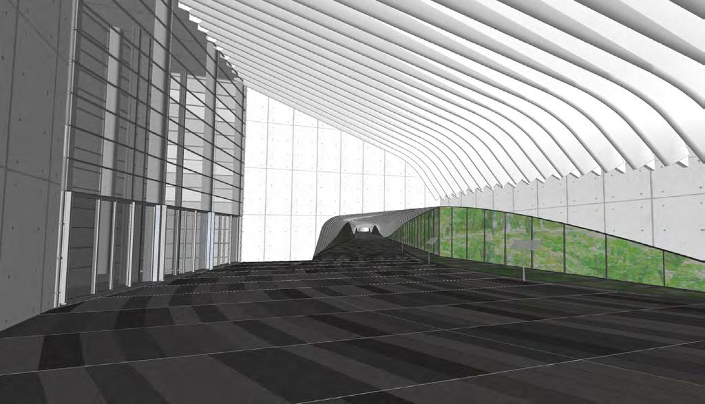
78 1st Street Entry Perspective 1st Street Entry Perspective Perspective from Elevator Bay Passageway Concept


79 Perspective from H Street Perspective of Passageway Entry on 1st Street Perspective of New North Mezzanine Entry
A. CONCLUSIONS OF THE FGEIS
 Chapter 11: Traffic and Parking A. CONCLUSIONS OF THE FGEIS The FGEIS found that the Approved Plan will generate a substantial volume of vehicular and pedestrian activity, including an estimated 1,300
CHAPTER 4: ALTERNATIVES
 MSP Long Term Comprehensive Plan Update Metropolitan Airports Commission 4.1 INTRODUCTION CHAPTER 4: ALTERNATIVES Several alternatives were developed and evaluated based on their capability to meet the
Appendix B Ultimate Airport Capacity and Delay Simulation Modeling Analysis
 Appendix B ULTIMATE AIRPORT CAPACITY & DELAY SIMULATION MODELING ANALYSIS B TABLE OF CONTENTS EXHIBITS TABLES B.1 Introduction... 1 B.2 Simulation Modeling Assumption and Methodology... 4 B.2.1 Runway
Arlington County Board Meeting Project Briefing. October 20, 2015
 Arlington County Board Meeting Project Briefing October 20, 2015 Project Map 2 Project Context Only Interstate in the Country limited to HOV only traffic during rush hours Stoplight at the end of I-66
Interstate 90 and Mercer Island Mobility Study APRIL Commissioned by. Prepared by
 Interstate 90 and Mercer Island Mobility Study APRIL 2017 Commissioned by Prepared by Interstate 90 and Mercer Island Mobility Study Commissioned by: Sound Transit Prepared by: April 2017 Contents Section
7272 WISCONSIN AVENUE LOCAL AREA TRANSPORTATION REVIEW
 7272 LOCAL AREA TRANSPORTATION REVIEW AND TRANSPORTATION POLICY AREA REVIEW MONTGOMERY COUNTY, MARYLAND Submitted on behalf of Carr Properties Prepared by: Wells + Associates, Inc. Submission: July 1,
5 Rail demand in Western Sydney
 5 Rail demand in Western Sydney About this chapter To better understand where new or enhanced rail services are needed, this chapter presents an overview of the existing and future demand on the rail network
TORONTO TRANSIT COMMISSION REPORT NO.
 Revised: March/13 TORONTO TRANSIT COMMISSION REPORT NO. MEETING DATE: November 18, 2013 SUBJECT: YONGE-EGLINTON AND EGLINTON WEST INTERCHANGE STATIONS METROLINX EGLINTON CROSSTOWN LIGHT RAIL TRANSIT PROJECT
5.1 Traffic and Transportation
 5.1 When it opens in 2009, the Bellevue Nickel Improvement Project will increase the number of vehicles able to travel through the study area, improve travel speeds, and improve safety by reducing the
Oakland A s Gondola Economic Impact
 January 2019 Oakland A s Gondola Economic Impact KEY FINDING: The proposed gondola system, which will connect the A s planned stadium to downtown Oakland, will generate $685 million in total economic benefit
Washington Metropolitan Area Transit Authority Services Utilization Study
 Washington Metropolitan Area Transit Authority Services Utilization Study Maryland House Bill 300 Table of Contents Page 2 Executive Summary Slide 3 Notes Slide 4 Metro Systemwide Fact Sheet Slide 5 How
McLean Citizens Association Transportation Committee Project Briefing
 McLean Citizens Association Transportation Committee Project Briefing November 10, 2015 Project Map 2 Project Context Only Interstate in the Country limited to HOV only traffic during rush hours Stoplight
NORTH FRASER PERIMETER ROAD WEST CORRIDOR DEFINITION STUDY
 NORTH FRASER PERIMETER ROAD WEST CORRIDOR DEFINITION STUDY MAY 2011 SW1132SWD NORTH FRASER PERIMETER ROAD WEST CORRIDOR DEFINITION STUDY TABLE OF CONTENTS 1.0 INTRODUCTION... 1 2.0 CURRENT TRAVEL PATTERNS
Appendix F International Terminal Building Main Terminal Departures Level and Boarding Areas A and G Alternatives Analysis
 Appendix F International Terminal Building Main Terminal Departures Level and Boarding Areas A and G Alternatives Analysis ITB MAIN TERMINAL DEPARTURES LEVEL & BOARDING AREAS A & G ALTERNATIVES ANALYSIS
Mount Pleasant (42, 43) and Connecticut Avenue (L1, L2) Lines Service Evaluation Study Open House Welcome! wmata.com/bus
 and Connecticut Avenue (L1, L2) Lines Service Evaluation Study Open House Welcome! wmata.com/bus") Mount Pleasant (42, 43) and Connecticut Avenue (L1, L2) Lines Service Evaluation Study Open House Welcome! Study Overview and Timeline Phase 1: Collect and Analyze Data Project Kickoff, September 2017
Mount Pleasant (42, 43) and Connecticut Avenue (L1, L2) Lines Service Evaluation Study Open House Welcome! Study Overview and Timeline Phase 1: Collect and Analyze Data Project Kickoff, September 2017
APPENDIX B. Arlington Transit Peer Review Technical Memorandum
 APPENDIX B Arlington Transit Peer Review Technical Memorandum Arlington County Appendix B December 2010 Table of Contents 1.0 OVERVIEW OF PEER ANALYSIS PROCESS... 2 1.1 National Transit Database...2 1.2
Union Station Queens Quay Transit Link Study
 Welcome Union Station in 1899. Image: City of Toronto Archives Union Station today. Image: Camil Rosiak Activity along Queens Quay. Image: Waterfront Toronto For more information or to comment, visit toronto.ca/waterfronttransit
Silver Line Operating Plan
 Customer Service and Operations Committee Information Item IV-A December 6, 2012 Silver Line Operating Plan Washington Metropolitan Area Transit Authority Board Action/Information Summary Action Information
3. Proposed Midwest Regional Rail System
 3. Proposed Midwest Regional Rail System 3.1 Introduction The proposed Midwest Regional Rail System (MWRRS) will operate in nine states, encompass approximately 3,000 route miles and operate on eight corridors.
Treasure Island Supplemental Information Report Addendum
 1 1 1 1 0 1 0 1 0 1 Treasure Island Supplemental Information Report Addendum Introduction Purpose The purpose of this Supplemental Information Report (SIR) Addendum is to determine if the current land
TORONTO TRANSIT COMMISSION REPORT NO.
 Form Revised: February 2005 TORONTO TRANSIT COMMISSION REPORT NO. MEETING DATE: SUBJECT: Resubmitted December 19, 2012 November 21, 2012 MODERNIZING THE TTC A NEW APPROACH TO COMMUNICATIONS, COMMUNITY
Crystal City Station Improvements. Project Overview. Table 2: North Entrance. Table 1: South Entrance. 20th St. S 18th St. S.
 Table 1: South Entrance Table 2: North Entrance 20th St. S 18th St. S Proposed Second Entrance Crystal Drive Existing Station Location Platform Future 4 th Track Future New Airport Connection (by others)
SRTA Year End Fixed Route Ridership Analysis: FY 2018
 SRTA Year End Fixed Route Ridership Analysis: FY 2018 2018 Contents Introduction... 1 A. Key Terms Used in this Report... 1 Key Findings... 2 A. Ridership... 2 B. Fare Payment... 4 Performance Analysis
SR 934 Project Development And Environment (PD&E) Study
 Study") SR 934 Project Development And Environment (PD&E) Study Project Advisory Group Meeting March 1, 2018 State Road 934/NE/NW 79th Street from west of I-95 (NW 13th CT) to N. Bayshore Drive PD&E STUDY SR 934/NE/NW
SR 934 Project Development And Environment (PD&E) Study Project Advisory Group Meeting March 1, 2018 State Road 934/NE/NW 79th Street from west of I-95 (NW 13th CT) to N. Bayshore Drive PD&E STUDY SR 934/NE/NW
APPENDIX H MILESTONE 2 TRAFFIC OPERATIONS ANALYSIS OF THE AT-GRADE CROSSINGS
 Draft Environmental Impact Statement/Environment Impact Report Appendix H Milestone 2 Traffic Operations Analysis of the At-Grade Crossings APPENDIX H MILESTONE 2 TRAFFIC OPERATIONS ANALYSIS OF THE AT-GRADE
EXHIBIT 1. BOARD AUTHORIZATION FOR PUBLIC HEARING AND SUBSEQUENT ISSUANCE OF A JOINT DEVELOPMENT SOLICITATION
 EXHIBIT 1. BOARD AUTHORIZATION FOR PUBLIC HEARING AND SUBSEQUENT ISSUANCE OF A JOINT DEVELOPMENT SOLICITATION Washington Metropolitan Area Transit Authority Board Action/Information Summary @Action O Information
TransAction Overview. Introduction. Vision. NVTA Jurisdictions
 Introduction Vision NVTA Jurisdictions In the 21 st century, Northern Virginia will develop and sustain a multimodal transportation system that enhances quality of life and supports economic growth. Investments
According to FAA Advisory Circular 150/5060-5, Airport Capacity and Delay, the elements that affect airfield capacity include:
 4.1 INTRODUCTION The previous chapters have described the existing facilities and provided planning guidelines as well as a forecast of demand for aviation activity at North Perry Airport. The demand/capacity
Capital & Counties. October 2007
 Capital & Counties October 2007 Contents!" # $ % % $ & ' "&( # Appendix 1 Appendix 2 1 Introduction 1.1.1 Wincheap regeneration scheme proposes a 600 space Park and Ride facility to replace the existing
Section 106 Update Memo #1 Attachment D. Traffic Diversion & APE Expansion Methodology & Maps
 Section 106 Update Memo #1 Attachment D Traffic Diversion & APE Expansion Methodology & Maps I-65/I-70 North Split Interchange Reconstruction Project (Des. Nos. 1592385 & 1600808) Traffic Diversion and
SAMTRANS TITLE VI STANDARDS AND POLICIES
 SAMTRANS TITLE VI STANDARDS AND POLICIES Adopted March 13, 2013 Federal Title VI requirements of the Civil Rights Act of 1964 were recently updated by the Federal Transit Administration (FTA) and now require
Bloor Street West Rezoning Application for a Temporary Use By-law Final Report
 STAFF REPORT ACTION REQUIRED 3741 3751 Bloor Street West Rezoning Application for a Temporary Use By-law Final Report Date: June 12, 2007 To: From: Wards: Reference Number: Etobicoke York Community Council
KING STREET TRANSIT PILOT
 KING STREET TRANSIT PILOT Update toronto.ca/kingstreetpilot #kingstreetpilot HIGHLIGHTS TRANSIT RIDERSHIP TRANSIT CAPACITY To respond to this growth in ridership, the TTC has increased the capacity of
Madison Metro Transit System
 Madison Metro Transit System 1101 East Washington Avenue Madison, Wisconsin, 53703 Administrative Office: 608 266 4904 Fax: 608 267 8778 TO: FROM: SUBJECT: Plan Commission Timothy Sobota, Transit Planner,
MEMORANDUM. Open Section Background. I-66 Open Section Study Area. VDOT Northern Virginia District. I-66 Project Team. Date: November 5, 2015
 MEMORANDUM To: VDOT Northern Virginia District From: I-66 Project Team Date: November 5, 2015 Subject: Open Section Background The purpose of this technical memorandum is to provide narrative and technical
Public Information Meetings. October 5, 6, 7, and 15, 2015
 Public Information Meetings October 5, 6, 7, and 15, 2015 Project Map 2 Project Context Only Interstate in the Country limited to HOV only traffic during rush hours Stoplight at the end of I-66 eastbound
Appendix 4.1 J. May 17, 2010 Memorandum from CTPS to the Inter Agency Coordinating Group
 Appendix 4.1 J May 17, 2010 Memorandum from CTPS to the Inter Agency Coordinating Group CTPS CENTRAL TRANSPORTATION PLANNING STAFF Staff to the Boston Region Metropolitan Planning Organization MEMORANDUM
DEVELOPMENT OF TOE MIDFIELD TERMINAL IROJECT CAPACITY ENHANCEMENT REPORT DEPARTMENT OF AVIATION TOM FOERSTER CHAIRMAN BARBARA HAFER COMMISSIONER
 PETE FLAHERTY COMMISSIONER TOM FOERSTER CHAIRMAN DEPARTMENT OF AVIATION BARBARA HAFER COMMISSIONER STEPHEN A. GEORGE DIRECTOR ROOM M 134, TERMINAL BUILDING GREATER PITTSBURGH INTERNATIONAL AIRPORT PITTSBURGH,
Addendum - Airport Development Alternatives (Chapter 6)
") Bowers Field Addendum - Airport Development Alternatives (Chapter 6) This addendum to the Airport Development Alternatives chapter includes the preferred airside development alternative and the preliminary
Bowers Field Addendum - Airport Development Alternatives (Chapter 6) This addendum to the Airport Development Alternatives chapter includes the preferred airside development alternative and the preliminary
WESTERN EL DORADO COUNTY SHORT AND LONG-RANGE TRANSIT PLAN Executive Summary
 WESTERN EL DORADO COUNTY SHORT AND LONG-RANGE TRANSIT PLAN Executive Summary Prepared for the El Dorado County Transportation Commission Prepared by The El Dorado County Transportation Commission (EDCTC)
Executive Summary. See Figure ES-5 on page 9. Figure ES-6: Typical At-Grade Alignment. Figure ES-7: Typical Underground Alignment
 Figure ES-5 shows all of the possible LRT routes and stations identified for study in the Draft EIS/EIR. The features and impacts of each of the build alternatives are described in the following section.
CHAPTER 5: Operations Plan
 CHAPTER 5: Operations Plan Report Prepared by: Contents 5 OPERATIONS PLAN... 5-1 5.1 Proposed Service Changes... 5-2 5.1.1 Fiscal Year 2017... 5-2 5.1.2 Fiscal Year 2018... 5-6 5.1.3 Fiscal Year 2019...
All Door Boarding Title VI Service Fare Analysis. Appendix P.3
 All Door Boarding Title VI Service Fare Analysis Appendix P.3 Metro Board Report Los Angeles County Metropolitan Transportation Authority One Gateway Plaza 3rd Floor Board Room Los Angeles,
KING STREET TRANSIT PILOT
 KING STREET TRANSIT PILOT Update toronto.ca/kingstreetpilot #kingstreetpilot UPDATE Average streetcar travel times in continued to show similar trends as first observed in November. The most significant
HOV LANE PERFORMANCE MONITORING: 2000 REPORT EXECUTIVE SUMMARY
 Final Report Research Project Agreement No. T1803, Task 4 HOV Monitoring V HOV LANE PERFORMANCE MONITORING: 2000 REPORT EXECUTIVE SUMMARY by Jennifer Nee TRAC Research Engineer John Ishimaru TRAC Senior
Table of Contents. List of Tables
 Table of Contents 1. Introduction... 1 2. Service Recommendations... 1 A. Extend Service on Fort Belvoir to New Post Exchange/Commissary Complex... 1 B. Improve Service Frequencies on Sunday from Current
Airport Planning Area
 PLANNING AREA POLICIES l AIRPORT Airport Planning Area LOCATION AND CONTEXT The Airport Planning Area ( Airport area ) is a key part of Boise s economy and transportation network; it features a multi-purpose
12, 14 and 16 York Street - Amendments to Section 16 Agreement and Road Closure Authorization
 REPORT FOR ACTION 12, 14 and 16 York Street - Amendments to Section 16 Agreement and Road Closure Authorization Date: April 27, 2018 To: Toronto and East York Community Council From: Senior Strategic Director,
Draft Concept Alternatives Analysis for the Inaugural Airport Program September 2005
 Draft Concept Alternatives Analysis for the Inaugural Airport Program September 2005 Section 3 - Refinement of the Ultimate Airfield Concept Using the Base Concept identified in Section 2, IDOT re-examined
MEMORANDUM. Lynn Hayes LSA Associates, Inc.
 MEMORANDUM To: Lynn Hayes LSA Associates, Inc. Date: May 5, 217 From: Zawwar Saiyed, P.E., Senior Transportation Engineer Justin Tucker, Transportation Engineer I Linscott, Law & Greenspan, Engineers LLG
I-66 Inside the Beltway Feasibility Study
 I-66 Inside the Beltway Feasibility Study Feasibility Study Study Process Context Sensitive Dialogues Corridor Assessments / Data Collection Problem Statement Refinement Concept Development Concept Evaluation
MEMORANDUM. for HOV Monitoring on I-93 North and the Southeast Expressway, Boston Region MPO, November, 2011.
 MEMORANDUM Date: January 12, 2012 To: Congestion Management Process Files From: Seth Asante, Ryan Hicks, and Efi Pagitsas MPO Staff Re: Historical Trends: Travel Times and Vehicle Occupancy Levels for
Draft Concept Alternatives Analysis for the Inaugural Airport Program September 2005
 Section 10 Preferred Inaugural Airport Concept 10.0 Introduction The Preferred Inaugural Airport Concept for SSA was developed by adding the preferred support/ancillary facilities selected in Section 9
DISTRICT EXPRESS LANES ANNUAL REPORT FISCAL YEAR 2017 JULY 1, 2016 JUNE 30, FloridaExpressLanes.com
 DISTRICT EXPRESS LANES ANNUAL REPORT FISCAL YEAR 2017 JULY 1, 2016 JUNE 30, 2017 FloridaExpressLanes.com This page intentionally left blank. TABLE OF CONTENTS List of Figures... ii List of Tables.... ii
TERMINAL DEVELOPMENT PLAN
 5.0 TERMINAL DEVELOPMENT PLAN 5.0 TERMINAL DEVELOPMENT PLAN Key points The development plan in the Master Plan includes the expansion of terminal infrastructure, creating integrated terminals for international,
Transportation Supporting Dulles Airport
 Transportation Supporting Dulles Airport Committee for Dulles Economic Development and Transportation Committee July 12, 2018 Tom Biesiadny, Director Fairfax County Multiple Transportation Improvements
FY Transit Needs Assessment. Ventura County Transportation Commission
 FY 18-19 Transit Needs Assessment Ventura County Transportation Commission Contents List of Figures and Appendices.. 2 Appendices... 1 Chapter 1: Introduction What is the Ventura County Transportation
Dufferin Jog Elimination Project
 Project Project Status Update November 14 2007 Project History Planning Alternatives Criteria Measured Project Benefits Structural Configurations Considered Structural Design Considerations The Preferred
TABLE OF CONTENTS. Coral Springs Charter High School and Middle School Job No Page 2
 Job No. 15-019 Page 2 TABLE OF CONTENTS 1.0 INTRODUCTION... 4 2.0 EXISTING CONDITIONS... 5 3.0 TRAFFIC GENERATION... 7 4.0 TRIP DISTRIBUTION... 8 5.0 FUTURE CONDITIONS... 8 6.0 SITE ACCESS...13 7.0 CONCLUSION...13
PREFACE. Service frequency; Hours of service; Service coverage; Passenger loading; Reliability, and Transit vs. auto travel time.
 PREFACE The Florida Department of Transportation (FDOT) has embarked upon a statewide evaluation of transit system performance. The outcome of this evaluation is a benchmark of transit performance that
REAL ESTATE TRANSACTION ADVISORY SERVICES
 REAL ESTATE TRANSACTION ADVISORY SERVICES Improving Performance and Value of Amtrak-owned Assets AMTRAK STATION DEVELOPMENT 1 New York Penn Station Moynihan Train Hall Philadelphia 30 th Street Station
Why we re here: For educational purposes only
 Transportation 2050 Why we re here: For educational purposes only Transportation 2050 Bus Elements PUBLIC TRANSIT DEPARTMENT City of Phoenix Citizens Committee on the Future of Phoenix Transportation (CCFPT)
Metro ExpressLanes April 5, 2011 Community Meeting re: Adams Blvd Improvements
 Metro ExpressLanes April 5, 2011 Community Meeting re: Adams Blvd Improvements Jan Perry Councilwoman, District 9 Welcome Remarks Arthur T. Leahy Chief Executive Officer, Metro Metro ExpressLanes Overview
Lake Erie Commerce Center Traffic Analysis
 LOCATION: East of NYS Route 5 at Bayview Road Town of Hamburg Erie County, New York PREPARED BY: Wendel Companies 140 John James Audubon Parkway Suite 200 Amherst, New York 14228 January 2012 i ii Table
NFTA Access Enhancement Study for Canalside and Cobblestone Alternatives Discussion. Alternative A South Park Avenue
 Alternative A South Park Avenue Alternative A Summary Alternative A extends Metro Rail service around the foot of Main Street east along South Park Avenue to serve a new station platform located along
Restoration of Historic Streetcar Services in Downtown Los Angeles
 Restoration of Historic Streetcar Services in Downtown Los Angeles Alternatives Analysis Community Update Meeting November 3, 2011 Introduction Local lead agency: Metro Federal lead agency: Federal Transit
APPENDIX D MSP Airfield Simulation Analysis
 APPENDIX D MSP Airfield Simulation Analysis This page is left intentionally blank. MSP Airfield Simulation Analysis Technical Report Prepared by: HNTB November 2011 2020 Improvements Environmental Assessment/
This report recommends two new TTC transit services in southwest Toronto.
 Report for Action New TTC Services - Southwest Toronto Date: March 20, 2018 To: TTC Board From: Chief Customer Officer Summary This report recommends two new TTC transit services in southwest Toronto.
METROBUS SERVICE GUIDELINES
 METROBUS SERVICE GUIDELINES In the late 1990's when stabilization of bus service was accomplished between WMATA and the local jurisdictional bus systems, the need for service planning processes and procedures
Chapter 3. Burke & Company
 Chapter 3 Burke & Company 3. WRTA RIDERSHIP AND RIDERSHIP TRENDS 3.1 Service Overview The Worcester Regional Transit Authority (WRTA) provides transit service to over half a million people. The service
Memorandum. Roger Millar, Secretary of Transportation. Date: April 5, Interstate 90 Operations and Mercer Island Mobility
 Memorandum To: From: The Honorable Dow Constantine, King County Executive; The Honorable Ed Murray, City of Seattle Mayor; The Honorable Bruce Bassett, City of Mercer Island Mayor; The Honorable John Stokes,
These elements are designed to make service more convenient, connected, and memorable.
 Transit is most attractive when it is frequent enough that people don t need to consult a timetable, and can instead just go to a stop and know that the train or bus will arrive shortly. Nearly all major
 Executive Summary This document contains the Master Plan for T. F. Green Airport. The goal of a master plan is to provide a framework of potential future airport development in a financially feasible manner,
Sky Temporary Car Park Transport Statement
 001 Issue 26 August 2016 This report takes into account the particular instructions and requirements of our client. It is not intended for and should not be relied upon by any third party and no responsibility
NAIOP. Marcia McAllister Metropolitan Washington Airports Authority
 NAIOP Marcia McAllister Metropolitan Washington Airports Authority 1 The Vision Realized Northern Virginia Today Tysons Corner is the largest employment center in the Commonwealth Larger than central business
WELLINGTON $422 MILLION $614 MILLION $83 MILLION 22% SPEND $1.9 BILLION
 WELLINGTON WELLINGTON $1.9 BILLION FORECAST TOTAL WELLINGTON INVESTMENT The Wellington region s transport challenges are dominated by the region s concentration of population in the metropolitan cities,
Aviation, Rail, & Trucking 6-1
 6-1 This chapter describes the services, facilities, and condition of air, rail, and trucking as components of the transportation system. These three intermodal areas have an impact on the factors to be
ROUTE EBA EAST BUSWAY ALL STOPS ROUTE EBS EAST BUSWAY SHORT
 ROUTE EBA EAST BUSWAY ALL STOPS ROUTE EBS EAST BUSWAY SHORT The EBA East Busway All Stops and EBS East Busway Short routes provide the core Martin Luther King Jr. East Busway services. Route EBA operates
Longmont to Boulder Regional Trail Jay Road Connection DRAFT FINAL REPORT
 Longmont to Boulder Regional Trail Jay Road Connection DRAFT FINAL REPORT December 2018 Project Summary Boulder County, Colorado, in partnership with the City of Boulder, is evaluating options for multi-use
FORECASTING FUTURE ACTIVITY
 EXECUTIVE SUMMARY The Eagle County Regional Airport (EGE) is known as a gateway into the heart of the Colorado Rocky Mountains, providing access to some of the nation s top ski resort towns (Vail, Beaver
10.0 Recommendations Methodology Assumptions
 10.0 Recommendations To accommodate the projected growth of the I-526 corridor, this report has summarized potential improvement strategies that were separated into four categories, TDM, Modal, Traffic
TRANSPORTATION ELEMENT
 Transportation TRANSPORTATION ELEMENT Data, Inventory, and Analysis Prepared by Contents 1.0 INTRODUCTION... 1 2.0 EXISTING CONDITIONS... 1 2.1 Roadways... 1 2.1.1 Jurisdiction... 1 2.1.2 Functional Classification...
Follow-up to Proposed Fare Changes for FY2013
 Finance & Administration Committee Information Item I-A January 19, 2012 Follow-up to Proposed Fare Changes for FY2013 1 of 22 Washington Metropolitan Area Transit Authority Board Action/Information Summary
Potomac River Commuter Ferry Feasibility Study & RPE Results
 1.1 Introduction The Prince William County Department of Transportation conducted a route proving exercise (RPE) and feasibility study of a proposed commuter ferry service on the Potomac River between
Stage 2 ION: Light Rail Transit (LRT) from Kitchener to Cambridge
 from Kitchener to Cambridge") Stage 2 ION: Light Rail Transit (LRT) from Kitchener to Cambridge Public Consultation Centre (PCC) No. 3 Please Sign-in Cambridge City Hall November 21, 2017 2:00 to 8:00pm Preston Memorial Auditorium
Stage 2 ION: Light Rail Transit (LRT) from Kitchener to Cambridge Public Consultation Centre (PCC) No. 3 Please Sign-in Cambridge City Hall November 21, 2017 2:00 to 8:00pm Preston Memorial Auditorium
National Society of Professional Engineers. Charles S. Carnaggio, PE Project Director July 2, 2014
 National Society of Professional Engineers Charles S. Carnaggio, PE Project Director July 2, 2014 Phase 1 Opening Date: July 26, 2014 Dulles Corridor Metrorail Project At-a-Glance Seamless integration
APPENDIX J MODIFICATIONS PERFORMED TO THE TOR
 APPENDIX J MODIFICATIONS PERFORMED TO THE TOR This appendix summarizes the modifications that were performed in years 2012 and 2017 to rectify calculation errors that were observed in the data presented
PUBLIC TRANSIT IN KENOSHA, RACINE, AND MILWAUKEE COUNTIES
 PUBLIC TRANSIT IN KENOSHA, RACINE, AND MILWAUKEE COUNTIES #118404v1 Regional Transit Authority June 19, 2006 1 Presentation Overview Existing Public Transit Transit System Peer Comparison Recent Transit
APPENDIX B COMMUTER BUS FAREBOX POLICY PEER REVIEW
 APPENDIX B COMMUTER BUS FAREBOX POLICY PEER REVIEW APPENDIX B COMMUTER BUS FAREBOX POLICY PEER REVIEW The following pages are excerpts from a DRAFT-version Fare Analysis report conducted by Nelson\Nygaard
FNORTHWEST ARKANSAS WESTERN BELTWAY FEASIBILITY STUDY
 FNORTHWEST ARKANSAS WESTERN BELTWAY FEASIBILITY STUDY EXECUTIVE SUMMARY The 2030 Northwest Arkansas Regional Transportation Plan developed by the Northwest Arkansas Regional Planning Commission (NWARPC)
City of Sacramento Sacramento Intermodal Transportation Facility Draft WP # 3 Transit Operational Requirements
 Sacramento Intermodal Transportation Facility Draft WP # 3 Transit Operational Requirements Contents 1 Introduction 1 2 Capitol Corridor Rail 3 2.1 Existing Operations 3 2.2 Future Plans 6 3 Amtrak Rail
Draft Environmental Assessment and Draft Section 4(f) Determination. Appendix A Station Headhouse Alternatives Analysis
 Determination. Appendix A Station Headhouse Alternatives Analysis") South Station Expansion March 2017 This Page Intentionally Left Blank South Station Expansion March 2017 South Station Expansion Project Draft Environmental Assessment and Draft Section 4(f) Determination
South Station Expansion March 2017 This Page Intentionally Left Blank South Station Expansion March 2017 South Station Expansion Project Draft Environmental Assessment and Draft Section 4(f) Determination
Chapel Hill Transit: Short Range Transit Plan. Preferred Alternative DRAFT
 : Short Range Transit Plan Preferred Alternative August 2018 Table of Contents Executive Summary... 1 Preferred Alternative... 3 Best Practices for Route Design... 3 Project Goals... 4 Preferred Alternative...
1.2 Corridor History and Current Characteristics
 SECTION 1 Description and Background of Study Area 1.1 Introduction This preliminary engineering report was prepared for the Alaska Department of Transportation and Public Facilities (ADOT&PF). It is part
London Borough of Barnet Traffic & Development Design Team
 London Borough of Barnet Traffic & Development Design Team AERODROME ROAD PEDESTRIAN FACILITY AND BUS STOP INTRODUCTION FEASIBILITY REPORT Job Number: 60668 Doc Ref: S106/12-13/60668 Author: Manoj Kalair
Foregone Economic Benefits from Airport Capacity Constraints in EU 28 in 2035
 Foregone Economic Benefits from Airport Capacity Constraints in EU 28 in 2035 Foregone Economic Benefits from Airport Capacity Constraints in EU 28 in 2035 George Anjaparidze IATA, February 2015 Version1.1
FUTURE PASSENGER PROCESSING. ACRP New Concepts for Airport Terminal Landside Facilities
 FUTURE PASSENGER PROCESSING ACRP 07-01 New Concepts for Airport Terminal Landside Facilities In association with: Ricondo & Associates, TransSolutions, TranSecure RESEARCH Background Research Objective
Update on the Thameslink programme
 A picture of the National Audit Office logo Report by the Comptroller and Auditor General Department for Transport Update on the Thameslink programme HC 413 SESSION 2017 2019 23 NOVEMBER 2017 4 Key facts
Assessment of Travel Trends
 I - 2 0 E A S T T R A N S I T I N I T I A T I V E Assessment of Travel Trends Prepared for: Metropolitan Atlanta Rapid Transit Authority Prepared by: AECOM/JJG Joint Venture Atlanta, GA October 2011 General
TORONTO TRANSIT COMMISSION REPORT NO.
 Revised: March/13 TORONTO TRANSIT COMMISSION REPORT NO. MEETING DATE: March 26, 2014 SUBJECT: KENNEDY INTERCHANGE STATION: METROLINX EGLINTON CROSSTOWN LIGHT RAIL TRANSIT PROJECT - PRELIMINARY CONCEPT