Merritt Island Airport
|
|
|
- Lorena Thomas
- 6 years ago
- Views:
Transcription
1 APPENDIX E RUNWAY SAFETY AREA DETERMINATION The purpose of this analysis is to evaluate existing deficiencies for Runway Safety Area (RSA) at Merritt Island Airport (COI) and to propose alternatives that comply with prescribed Federal Aviation Administration (FAA) standards. Recognizing that conformity with RSA criteria may be challenging, an initial meeting between the Titusville-Cocoa Airport Authority (TICO), LPA and FAA Airport Districts Office (ADO) was held to discuss historic modifications to standards, non-standard design and RSA issues at COI. As a result of that meeting, this study was developed to evaluate the critical Airplane Design Group (ADG) and RSA requirements in order to maximize the utilization of the runway without compromising safety standards as set forth in FAA Order , Runway Safety Area Program. In order to complete this analysis of RSA, a combination of the following corrective measures must be considered: declared distances, Engineered Materials Arresting System (EMAS), cut and fill, runway relocation, shifting, or realignment, or a combination of thereof. Additional consideration was also be given to object free areas, Part 77 surfaces, and building restriction lines that are used to establish proposed development areas adjacent to Runway Further, since the airport is surrounded on three sides by the Intracoastal Waterway (Newfound Harbor), all proposed RSA improvements will include reconstruction of the seawall. RSA-RUNWAY ENVIRONMENT RELATIONSHIP The RSA is an integral part of the runway environment. RSA dimensions are established in FAA AC 150/ , Airport Design, and are based upon the Airport Reference Code (ARC). The RSA is intended to provide a measure of safety in the event of an aircraft s excursion from the runway by significantly reducing the extent of personal injury and the hazard of structural damage during aircraft overruns, undershoots and lateral veering. Many circumstances contribute to the potential for aircraft excursions including insufficient runway length, pilot error, weather conditions with low visibility, site constraints including precipitous terrain drop-offs, bodies of water, wetlands, residential or commercial development, availability of visual and electronic aids for landing, as well as runway contamination caused by rain, snow, and ice. In addition, mechanical failure may inhibit an aircraft s propensity to decelerate in time during landing or during an aborted takeoff. The function of the RSA is to create a buffer between the runway pavement and nonmovement areas. Takeoffs and landings are generally regarded as the most critical phases of flight where more than 60 percent of aircraft accidents occur. During these segments, aircraft are subject to a variety of controls and operational factors including a runway s usable operating dimensions. A growing list of RSA related accidents has contributed to E-1 RSA Determination
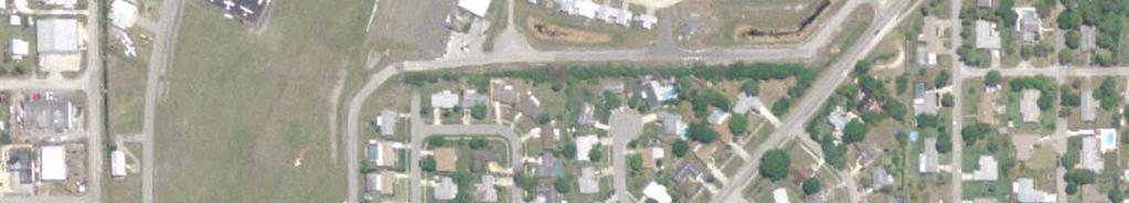
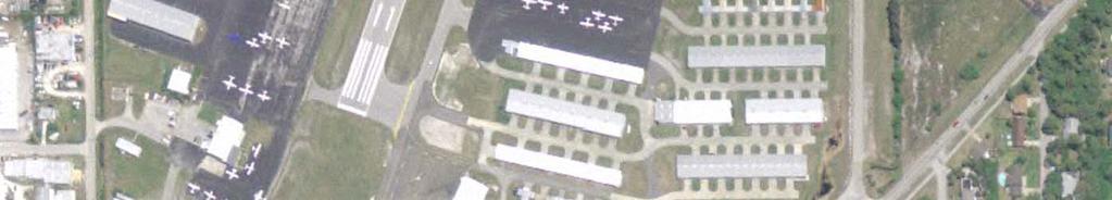
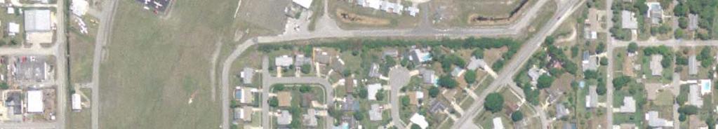
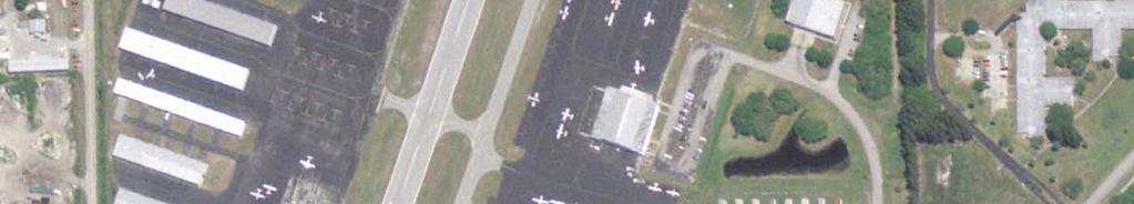
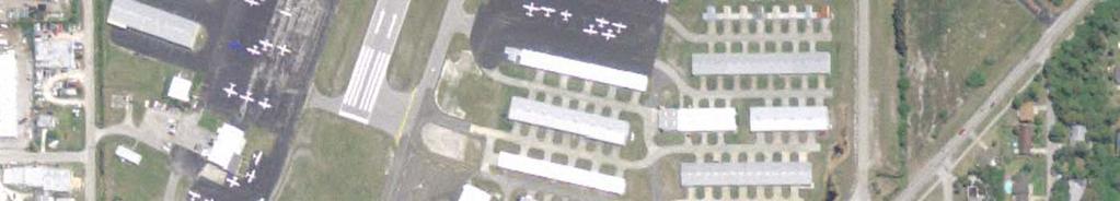
2 the mounting concern that airports do not provide adequate safety areas to reduce injury to persons and property. As a result, state and federal legislation was enacted in an effort to standardize safety area requirements. The FAA coordinated a study in 1990 which identified airports currently not in compliance with RSA design requirements. Recognizing the significant safety enhancement afforded by RSA improvements, the FAA issued Order , Runway Safety Area Program, in an effort to guide the improvement process by identifying potential alternatives to the traditional cleared and graded safety areas as illustrated in Figure E-1. Figure E-1, Standard Runway Safety Area (RSA) Profile Length Structural Pavement Width RSA RSA TORA TODA ASDA LDA Source: The LPA Group Incorporated, As shown, the RSA profile runs beyond the structural pavement of the runway along the extended runway centerline. As previously mentioned, the width and length of the RSA is dependent upon the most critical aircraft using the runway. Figure E-1 represents the traditional cleared and graded safety areas in which sufficient land can be accommodated beyond both runway ends, without the need to displace any thresholds. In this situation, the full length of the runway may be used for aircraft movement. However, as explored later in this document, alternative RSA accommodations may be achieved by employing other means if conditions permit. EXISTING CONDITIONS Airfield Overview COI s single runway system, Runway 11-29, has a published length of 3,601 feet and width of 75 feet. The runway is supplemented by two parallel taxiways Taxiway A is a full-length parallel taxiway on the southern side and Taxiway B is a 2,300 foot long partial-parallel taxiway on the northwestern side of the runway. Various connector taxiways provide access between the runway, parallel taxiways, and landside areas. As illustrated in Figure E-2, the airport property lies on a peninsular landmass, with the southeastern end of the runway (Runway 29 end) surrounded on three sides by the Intracoastal Waterway (Newfound Harbor). E-2 RSA Determination
3 FAA Advisory Circular (AC) 150/ , Airport Design, characterizes an Airport Reference Code (ARC) as a coding system used to relate airport design criteria to the operational and physical characteristics of aircraft operating or anticipated to operate at an airport. Each dimensional criterion is specified based on aircraft approach category, represented by a letter A-E corresponding to aircraft approach speed in knots, and airplane design group, represented by a Roman numeral I-VI corresponding to aircraft wingspan in feet. The alphanumeric coding system is most often used to describe the airport s capacity to handle aircraft that correspond to approach speed and wing span. It is also used to determine runway-specific handling capacity. Table E-1 summarizes the elements of these categorizations. TABLE E-1 FAA REFERENCE CODE CLASSIFICATIONS Aircraft Approach Aircraft Approach Speed Airplane Design Category (AS) in Knots Group Aircraft Wingspan (WS) A AS < 91 I WS < 49 ft B 91 < AS < 121 II 49 ft < WS < 79 ft C 121 < AS < 141 III 79 ft < WS < 118 ft D 141 < AS < 166 IV 118 ft < WS < 171 ft E 166 < AS V 171 ft < WS < 214 ft VI 214 ft < WS < 262 ft Source: The LPA Group Incorporated, In Chapter 4, Demand Capacity/Facility Requirements, the airport s existing and future ARC was identified as B-I light. The light designation is applied to airports that predominately serve small aircraft with maximum takeoff weights of 12,500 pounds or less, and coincides with the most demanding aircraft that operates and performs at least 500 operations per year at the airport. While larger category aircraft currently utilize COI on an occasional basis, such as the Beechcraft King Air 200 with an ARC of B-II, the primary operator of those aircraft, Baer Air, intends to shift operations from COI to Melbourne International and Flagler County Airports (MLB and XFL). As a result, the number of B-II aircraft operations is expected to decrease at COI. Since the airport s facilities were constructed based upon the B-I light design requirements, it was recommended by the ADO that larger aircraft, B-II or greater, provide notice to the TICO Airport Authority prior to operating at the COI. This will provide another level of safety since the airport is not currently equipped with an Air Traffic Control Tower (ATCT). E-3 RSA Determination
4
5 Existing Runway Design Specifications The FAA sets forth particular dimensional criteria for runway design and runway separation standards. These standards reflect the variation in aircraft design dimensions and provide safety clearance between taxiway and runway environments. These dimensions are fundamental components that establish an index from which RSA dimensional criteria are determined. This section will investigate the existing runway design elements at COI and will facilitate the discussion for recommending alternative modifications to RSA elements that are presented later in this appendix. Runway Runway has a weight bearing capacity of 22,000 pounds for aircraft with a singlegear configuration. Criteria outlined by the FAA state that for the ARC B-I light designation a runway width of 60 feet is required. Currently, Runway has a published width of 75 feet which exceeds FAA standards. However, no width reduction is recommended as part of the, so the airport may continue to safely accommodate B-II single and dual-wheel aircraft. The current runway centerline to parallel taxiway centerline offset between Runway and the parallel taxiways is 150 feet, which also meets FAA criteria for ARC B-I light. Table E-2 identifies various FAA design standard criteria in comparison to the existing characteristics of the airfield at COI. Runway is also served by two non-precision instrument approaches to Runway 11. These consist of straight-in approaches to the runway end via horizontal guidance to pilots only vertical guidance is only provided with a precision instrument approach. The existing approaches to Runway 11 include: Global Positioning System (GPS) based approach that provides visibility minimums as low as one-mile; and Non-Directional Beacon (NDB) based approach that also provides visibility minimums as low as onemile. No published approaches exist or are recommended for Runway 29 primarily due to controlled and restricted airspace south and east of the airport (e.g., Patrick Air Force Base and NASA restricted airspace). E-5 RSA Determination
6 TABLE E-2 EXISTING B-I DIMENSIONAL STANDARDS Design Standard Runway Existing FAA Standard B-I Dimension Runway to Taxiway A 150 ft 150 ft Runway to Taxiway B 150 ft 150 ft Runway Width 75 ft 60 ft RSA Length beyond Runway End 240 ft 60 ft 240 ft RSA Width 120 ft 120 ft 120 ft ROFA Width 250 ft 250 ft 250 ft ROFA Length beyond Runway End 240 ft 240 ft 240 ft Sources: AC 150/ and The LPA Group Incorporated, DEVELOPMENT CONSIDERATIONS Background This section presents initial development considerations assessed given the airport s operational characteristics, number of historical incidents and/or accidents, and forecast future fleet mix. Since Runway is the only available runway at COI, maintaining the current runway length for both takeoff and landing is considered of primary importance for continued operational safety and for the continued sustainability of existing based airport businesses. Because Runway is only 3,601 feet, partially surrounded by water, and regularly used by larger B-II aircraft, maintaining the current runway length is vital for maintaining the overall safety of the airfield. Further, potentially shifting operations toward the Runway 11 threshold would increase noise exposure to residential properties located approximately 400 feet north and west of the Runway 11 threshold. The FAA and National Transportation Safety Board (NTSB) maintain databases of aircraft incidents and accidents that occurred at the airport and the causes of those events. The FAA Aircraft/Incident Data System (AIDS) database contains incident records for all categories of civil aviation incidents that have been recorded at COI since November 4, 2008 as shown in Table E-3. According to the FAA, incidents are defined as events that do not meet the aircraft damage or personal injury thresholds contained in the NTSB definition of an accident. For example, the database contains reports of collisions between aircraft and birds while on approach to or departure from an airport. While such a collision may not have resulted in sufficient aircraft damage to reach the damage threshold of an NTSB accident, the fact that the collision occurred is valuable safety information that may be used in the establishment of aircraft design standards or in programs to deter birds from nesting in areas adjacent to airports. The FAA incident records in Table E-3 show several aircraft roll-outs from the runway during takeoff and E-6 RSA Determination
7 landing, thus illustrating the historical need for standard RSA at the airport. Additionally, the NTSB accident data in Table E-4 identifies known accidents that have occurred within the RSA beyond either end of Runway 11-29, including at least one that consisted of an aircraft landing short of Runway 29 and subsequently crashing in the Intracoastal Waterway (Newfound Harbor). Incidents and accidents at COI have historically ranged from minor incidents with little damage to major accidents. Most accidents were acerbated by the lack of standardized safety area beyond the Runway 29 threshold. Further, since Runway 11 is the primary takeoff runway at COI, providing standard RSA beyond Runway 29 is critical in the event of an aborted takeoff. In evaluating potential RSA options, it is necessary to identify the future fleet mix at an airport. COI as part of the TICO Aviation System will remain a general aviation (GA) airport. However, the airport is poised to attract a sizeable number of new-era micro or very light jet (VLJ) aircraft, which were introduced in part with the Small Aircraft Transportation System (SATS). For example, in Chapter 3, Aviation Activity Forecasts, the number of VLJ operations at COI is forecast to increase from zero in 2007 to 4,860 by 2027, thus presenting a whole new class of aircraft into the regular activity mix at COI. These turbine-powered aircraft are expected to serve smaller communities because of their propensity to operate on shorter runways than typical turbine powered aircraft. As a result, micro jets are anticipated to increase and bring new business activity to small GA airports around the country. These micro jets are classified by their weight and existing prototypes are less than 12,500 pounds. Accordingly, this singular operational characteristic does not require additional runway lengthening at COI to accommodate VLJ aircraft, although RSA improvements are still necessary. In FAA Order , Runway Safety Area Program, five specific alternatives are to be considered for those safety areas that are unable to meet the traditional graded area surrounding the runway. The alternatives evaluation process was resolved through a twostep process that first subjected all design options to a preliminary screening review. In order to achieve the best option for RSA improvements at COI, several alternatives were subsequently analyzed, scrutinized, and then ranked reflecting several factors including cost, environmental impact, safety, and operational efficiency. These alternatives were then refined to include design considerations identified as the most practicable for COI, which are detailed more thoroughly in the later sections of this appendix. E-7 RSA Determination
8 TABLE E-3 FAA INCIDENT DATA Event Date Airport Name Event Type Aircraft Damage Phase of Flight Aircraft Make Name Aircraft Model Name 30-Apr-08 MERRITT ISLAND INCIDENT - GENERAL AVIATION MINOR ROLL-OUT (FIXED WING) PIPER PA-28 6-Nov-07 MERRITT ISLAND INCIDENT - GENERAL AVIATION MINOR LEVEL OFF TOUCHDOWN BEECH BE-35 1-Oct-06 MERRITT ISLAND INCIDENT - GENERAL AVIATION MINOR TAKEOFF GROUND ROLL 17-Aug-05 MERRITT ISLAND INCIDENT - GENERAL AVIATION MINOR NORMAL CRUISE CESSNA CE Aug-04 MERRITT ISLAND INCIDENT - GENERAL AVIATION MINOR ROLL-OUT (FIXED WING) 8-Feb-04 MERRITT ISLAND INCIDENT - GENERAL AVIATION MINOR ROLL-OUT (FIXED WING) NAMER SNJ-4 10-Mar-03 MERRITT ISLAND INCIDENT - GENERAL AVIATION MINOR ROLL-OUT (FIXED WING) 21-Feb-03 MERRITT ISLAND INCIDENT - GENERAL AVIATION MINOR FORCED LANDING BEECH BE Jan-03 MERRITT ISLAND INCIDENT - GENERAL AVIATION MINOR ROLL-OUT (FIXED WING) BEECH BE May-02 MERRITT ISLAND INCIDENT - GENERAL AVIATION MINOR GROUND TAXI, OTHER AIRPLANE 14-Apr-02 MERRITT ISLAND INCIDENT - GENERAL AVIATION MINOR TAKEOFF GROUND ROLL 15-Aug-01 MERRITT ISLAND INCIDENT - GENERAL AVIATION MINOR ROLL-OUT (FIXED WING) PIPER PA-46 5-Aug-01 MERRITT ISLAND INCIDENT - GENERAL AVIATION MINOR LEVEL OFF TOUCHDOWN BLANCA BL-7 4-Dec-99 MERRITT ISLAND INCIDENT - GENERAL AVIATION MINOR LEVEL OFF TOUCHDOWN MOONEY M Aug-99 MERRITT ISLAND INCIDENT - AIR CARRIER MINOR GROUND TAXI, OTHER AIRPLANE PIPER PA May-99 MERRITT ISLAND INCIDENT - GENERAL AVIATION MINOR LEVEL OFF TOUCHDOWN 1-Jan-99 MERRITT ISLAND INCIDENT - GENERAL AVIATION MINOR TAKEOFF GROUND ROLL PIPER PA Oct-97 MERRITT ISLAND INCIDENT - GENERAL AVIATION MINOR LEVEL OFF TOUCHDOWN BEECH BE Mar-97 MERRITT ISLAND INCIDENT - GENERAL AVIATION MINOR ROLL-OUT (FIXED WING) CESSNA CE Jun-93 MERRITT ISLAND INCIDENT - GENERAL AVIATION MINOR ROLL-OUT (FIXED WING) PIPER PA Jul-92 MERRITT ISLAND INCIDENT - GENERAL AVIATION MINOR LEVEL OFF TOUCHDOWN GULSTM GA-AA 3-Apr-92 MERRITT ISLAND INCIDENT - GENERAL AVIATION MINOR LEVEL OFF TOUCHDOWN MOONEY M Apr-91 MERRITT ISLAND INCIDENT - GENERAL AVIATION MINOR LEVEL OFF TOUCHDOWN CESSNA CE Apr-90 MERRITT ISLAND INCIDENT - GENERAL AVIATION MINOR ROLL-OUT (FIXED WING) BLANCA BL-8 4-Nov-88 MERRITT ISLAND INCIDENT - GENERAL AVIATION MINOR FORCED/PRECAUTIONARY LANDING Sources: FAA Accident/Incident Data System, The LPA Group Incorporated, TABLE E-4 NTSB ACCIDENT DATA Event Date Phase of Flight Crash Site Fatalities Injuries Aircraft Type 21-Feb-03 Landing - RW 29 Beyond RW Beech A45 8-Aug-02 Landing - RW 11 Beyond RW Aviat Aircraft Inc. A1 17-Aug-86 Landing - RW 29 In Water Beyond RW Champion / 7KCAB Sources: NTSB Accident Database, The LPA Group Incorporated, E-8 RSA Determination
9 Runway Relocation, Shifting, or Realignment Existing RSA deficiencies at COI are a direct result of the constrained land mass on which the airport is situated. The topography and environmental habitats surrounding COI limits runway lengthening and the sensitivity of such require that RSA deficiencies be resolved by other means. The proximity of Runway to the Intracoastal Waterway (Newfound Harbor) requires RSA modifications to extend into the water, which involves dredging and filling portions of the Intracoastal to regain safety area beyond Runway 29 which has eroded over the years. As illustrated in Figure E-2 (on page E-4), the airport property line extends approximately 200 feet beyond the end of Runway 29 into the Intracoastal. As a result, an additional 40+ feet is required to accommodate the standardized safety area and associated seawall. However, according to property information, a Corrective Dedication of Clear Zone Easement No A provided by the grantor, Trustees for the Internal Improvement Fund State of Florida, issued in 1965 (Figure E-3) shows a dedicated clear zone area beyond the existing airport property boundary. This clear zone area has the following dimensions: 260 feet x feet x 350 feet. Therefore, since an easement already exists, it may be possible to obtain the additional property required to accommodate safety area and seawall requirements. Still, since this will require the cut and fill of portions of the Intracoastal Waterway, careful consideration of potential environmental impacts must be undertaken. Subsequently, due to land constraints and nearby residential properties located approximately 400 feet beyond Runway 11, no feasible alternatives were identified for relocating, shifting, or realigning Runway at COI. Specifically, no feasible development options could be identified for these alternatives which would not require significant impacts to existing airport infrastructure, large-scale dredging and filling, and/or required acquisition of residential properties. Options for such development were initially considered and dismissed, based on discussions with the TICO and FAA. Therefore, other alternatives as prescribed in FAA Order , Runway Safety Area Program, were investigated for COI. E-9 RSA Determination

10 Figure E-3 Corrective Dedication of Clear Zone Easement No A Sources: Brevard County Property Appraisers Office, 1965 and the LPA Group Incorporated, 2008 E-10 RSA Determination
11 Runway Length Reduction The consideration for runway length reduction is plausible only when existing runway length exceeds that which is required to accommodate the existing and/or projected critical design aircraft. In this regard, several factors and operational characteristics at COI make any reduction in the runway length ineffective including: In Chapter 4, Demand Capacity/Facility Requirements, the runway length requirement for COI was determined to be 3,700 feet, which is 99 feet greater than currently provided by Runway As such, many existing small aircraft users of the airport would not be able to operate with the same capability as currently provided if the runway length were further reduced. Runway length is critical to many of the businesses based at the airport, particularly those which conduct training operations. Consequently if the runway length were reduced, those businesses may not be able to offer the same types of operations, potentially resulting in relocation to another airport, financial loss, etc. Residential development is currently located approximately 400 feet beyond the end of Runway 11. Reduction in the runway length could increase the potential for an accident to occur within this residential area. Additionally, reduction in the runway length could increase aircraft noise exposure within this residential area. Therefore, if at all possible, options that included a reduction in the runway length were not recommended so that impacts to current airport users, businesses, and surrounding property owners could be avoided. Regardless, to further emphasize these potential impacts, one of the RSA alternatives, Alternative C, illustrates a runway length reduction through the relocation of the Runway 29 threshold. Combination of Runway Relocation, Shifting, or Reduction As mentioned in the sections above, alternatives that relocate, shift, realign, or reduce the length of Runway are not considered effective for COI because of land constraints and the need to maintain the current runway length to prevent serious safety threats to the residential properties currently located approximately 400 feet beyond the end of Runway 11. Declared Distances In cases where standardizing RSA is impracticable, an alternative to achieving RSA is determined through the use of declared distances. The FAA revised its standards for runway safety area and linked its design characteristics with declared distance information in AC 150/ , Airport Design. In previous versions of the advisory circular, FAA set forth precise and uniform design characteristics for RSA, which established identical dimensions beyond both runway ends. Cognizant that some airports are unable to adhere and comply with these specifications, the FAA incorporated an alternative clause that asserts RSAs may be defined within the confines of the runway E-11 RSA Determination

12 structural pavement by using declared distances. Consequently, takeoff run available (TORA) would be reduced by the same factor as the standard RSA beyond the runway threshold. The refined RSA area, therefore, would be located or overlap the runway structural pavement. As a result, the pavement area under which the relocated RSA is defined may not be used for specific operational calculations. As illustrated in Figure E-4, the declared distance alternative allows the airport to determine what portions of an operational runway can be considered to satisfy an aircraft s accelerate-stop, takeoff, and landing distance requirements while still complying with standard RSA requirements. This option allows the implementation of declared distances for those airports that cannot provide sufficient distance beyond the runway ends. A brief description of each declared distance is denoted in the following. Takeoff Run Available (TORA) the distance to accelerate from brake release to lift-off plus safety factors. Takeoff Distance Available (TODA) the distance to accelerate from brake release past lift-off to start of takeoff climb plus safety factors. Accelerate-Stop Distance Available (ASDA) the distance to accelerate from brake release to V 1 and then decelerate to a stop, plus safety factors. Landing Distance Available (LDA) the distance from the threshold to complete the approach, touchdown, and decelerate to a stop, plus safety factors. Figure E-4, Declared Distances Sample Schematic TORA Source: FAA Presentation (Airports Annual Conference), The LPA Group Incorporated, Declared distances are not currently in effect for Runway Given the property constraints of the airport and the need to maintain the full length to accommodate existing E-12 RSA Determination
13 airport users, declared distances would not be effective to implement since it would result in a permanent reduction in runway length (for either takeoff or landing, depending upon implementation). Unless the runway and associated RSA were extended in either direction through other methods such as dredge and fill and/or property acquisition, there would be no other possible way to maintain the existing runway length for both takeoff and landing. Consequently since a runway extension in either direction is infeasible at COI, declared distances are also considered infeasible. Regardless, to further emphasize these potential impacts, one of the RSA alternatives (Alternative A) illustrates the use of declared distances to correct the non-standard RSA beyond Runway 29. Engineered Materials Arresting System (EMAS) On occasion, aircraft can and do overrun the ends of runways. An overrun occurs when an aircraft surpasses the pavement confines of a runway environment and proceeds into an unpaved area of the airfield not designated for aircraft use. Aircraft overruns usually occur during landing and aborted takeoffs, during which aircraft are unable to sufficiently decelerate in time to remain on existing runway pavement. According to FAA AC 150/ , Engineered Materials Arresting Systems for Aircraft Overruns, the majority of these aircraft come to rest within 1,000 feet of the runway end and between the extended edges of the runway. Data collected by the FAA over a 12-year period between 1975 and 1987 indicate that nearly 90 percent of aircraft overruns occur at exit speeds of 70 knots or less. Based upon the potential hazards these incidents may cause, the FAA incorporated a model of RSAs into airport design standards. In compliance with these standards, the RSA must be capable, under normal (dry) conditions, of supporting aircraft that overrun the runway without causing structural damage to aircraft or injury to its occupants. However, many airports face the issue of natural obstacles, encroaching development, or environmental restrictions that prohibit the feasible development of these RSAs. Due to the difficulty associated with attaining a standard RSA at many airports, the FAA spearheaded research to explore the use of various materials for arresting systems. Commonly referred to as Engineered Materials Arresting System (EMAS), this initiative has gained widespread support. An EMAS is designed to stop an aircraft during an overrun by exerting predictable deceleration forces on its landing gear. The EMAS is considered fixed by its function and frangible by its design and is intended to fail at a specific impact load. EMAS structures are sloped and built above the existing grade to absorb the aircraft s velocity and forward movement. Centered on the extended runway centerline, the EMAS structure is located beyond the end of the runway at a distance determined by available land area and EMAS materials. COI EMAS Evaluation A core objective of any airport improvement project is balancing effectiveness and cost. The EMAS alternative would be a reasonable means of achieving RSA if the expected E-13 RSA Determination
14 level of operational activity and fleet diversity were expected to increase over the planning horizon. However, COI s role within the aviation system will remain as an important general aviation facility predominately serving the needs of aircraft with maximum certificated takeoff weights of 12,500 pounds or less. As described in the previous section, design characteristics that dictate the construction of the EMAS bed is based upon historical data formerly obtained by the FAA. The structural integrity of the EMAS is contingent upon several variables that affect the way in which the structure fails upon impact, including the impact load in terms of weight and velocity of the aircraft prior to contact with the arrestor bed. Thus, the design aircraft at COI, both existing and expected in the near term, are not compatible with the design attributes of the EMAS, which is intended to arrest heavier aircraft with greater exit speeds. Therefore, for the purposes of this analysis, further consideration was not given to the EMAS alternative as its function is infeasible for the type of operational activity at COI. ALTERNATIVES EVALUATION Compliance with FAA mandated RSA requirements may be attained via several alternatives, each having distinctive benefits and associated disadvantages. As previously emphasized, achieving these standards may be afforded by implementing non-standard substitutes to RSA dimensions published in FAA AC 150/ , Airport Design, as practicable. Additionally, the unique property of COI demands additional consideration to be given to potential environmental impacts, which are discussed later in this appendix. Therefore, based upon the four potential alternatives outlined by the FAA, three potentially viable alternatives were developed specific to COI including: Alternative A RSA Fulfillment Using Declared Distances Only Alternative B RSA Fulfillment Using Dredge and Fill Alternative C RSA Fulfillment Using Relocated Thresholds As mentioned earlier, seawall reconstruction is required no matter which preferred RSA alternative is recommended. Therefore, the preliminary environmental assessment and cost estimates include seawall improvements. E-14 RSA Determination
15 Alternative A RSA Fulfillment Using Declared Distances Only As mentioned earlier, the assimilation of declared distances resolves RSA deficiencies by diminishing runway landing and takeoff lengths independently. Airports that implement this methodology publish their declared distances in airport facility directories and other pilot resources. These resources are consulted to determine landing and departure accommodations relative to a specific runway. As shown in Figure E-5, Alternative A assumes no structural modifications to the RSA. Rather, it incorporates adjustments to the takeoff run available (TORA) and to the landing distance available (LDA) in order to meet B-II RSA criteria. Additionally, seawall improvements along the airport s coastal boundary, for a length of approximately 2,700 feet, are included in this alternative to prevent further erosion of the coast and to stabilize the RSA area beyond Runway 29. The existing available RSA length beyond the Runway 29 end is approximately 60 feet, as previously noted in Table E-2. To achieve a standard 240 foot RSA beyond this runway end for B-I light aircraft, 180 feet of usable pavement area must be sacrificed, thereby reducing the TORA to 3,421 feet for operations on Runway 11, and the LDA to 3,421 for operations on both runway ends. Table E-5 outlines the declared distances associated with Alternative A. TABLE E-5 RUNWAY DECLARED DISTANCES Declared Distance Runway 11 Runway 29 Displaced Threshold 0 ft 180 ft TORA 3,421 ft 3,601 ft TODA 3,421 ft 3,601 ft ASDA 3,421 ft 3,601 ft LDA 3,421 ft 3,421 ft Sources: The LPA Group Incorporated, Although this alternative is considered cost effective since it requires no construction to correct the RSA shortfall, it will limit aircraft use on Runway Further, the costs for seawall improvements would be substantial under any of the alternatives which are needed to stabilize the airport s coastal boundary and RSA area. Regarding Alternative A, a sizeable portion of pavement is sacrificed so that ARC B-I light RSA criterion can be achieved. While maintaining satisfactory dimensions for RSA is crucial, the reduction of runway pavement, especially at a single runway airport, as a means of doing so reduces the airport s operating capacity to serve particular aircraft and may lead to a reduction in the airport s future role within the aviation system. Specifically, the length available for aircraft landing (i.e., LDA) is permanently reduced through the use of declared distances. E-15 RSA Determination


16
17 Since aircraft landing on Runway 29 would be provided with less available landing length, the operational safety of the airport would be reduced for existing airport users potentially posing a serious safety threat to nearby residential properties. In addition considerations mentioned the relocated landing threshold would further require the relocation of the Precision Approach Path Indicator (PAPI) and Runway End Identifier Lights (REILs) associated with the Runway 29 approach. Anticipated order of magnitude costs associated with Alternative A are provided in Table E-6. TABLE E-6 ALTERNATIVE A ORDER OF MAGNITUDE COSTS Project Estimated Costs Remark Runway Markings $20,000 Relocate PAPI and REILs on Runway 29 $30,000 Seawall design and construction $4,800,000 Environmental Assessment & Permitting $500,000 Total $5,350,000 Source: The LPA Group Incorporated, Alternative B RSA Fulfillment Using Dredge and Fill In an effort to preserve the entire operating length of Runway 11-29, dredge and fill could be used to regain the runway safety area lost through erosion. Because of continued disintegration of both the seawall and safety area, only 60 feet of graded property is usable beyond the Runway 29 threshold. To obtain the safety area required, approximately 0.33 acres of land would need to be acquired, as illustrated in Figure E-6. In conjunction with the RSA, seawall improvements were also considered. Based upon structural requirements, 5,630 cubic yards (CY) of dredge and 16,889 CY of fill is required to accommodate both improvements. Further, unlike the Alternatives A and C, Alternative B does not require the remarking of the runway pavement and relocation of either the PAPI-4 or REILs. This method of attaining runway safety area requirements is costly but may qualify for FAA funding assistance. Additionally, an environmental assessment of this area is required to determine the significance and extent of environmental impacts, specifically presence of benthic invertebrate communities as required by FAA Order E, Environmental Impacts: Policies and Procedures. E-17 RSA Determination


18
19 Anticipated order of magnitude costs associated with Alternative B are shown in Table E-7. TABLE E-7 ALTERNATIVE B ORDER OF MAGNITUDE COSTS Project Estimated Costs Engineering Design $300,000 Environmental Assessment & Permitting $275,000 Environmental Mitigation $600,000 Administration & Testing $180,000 Construction (Seawall and RSA) $5,400,000 Total $6,755,000 Source: The LPA Group Incorporated, Alternative C RSA Fulfillment Using Relocated Thresholds A third alternative for providing RSA criteria is permanently relocating the Runway 29 threshold approximately 180 feet to the northwest. In relocating the threshold, unlike the use of declared distances, the pavement beyond the threshold cannot be used for aircraft operations. The relocated threshold is marked by a demarcation bar, which is a 10-footwide white-painted stripe that extends across the width of the runway. The distance between the beginning of the runway pavement and the relocated threshold will be remarked with yellow-painted chevrons, indicating that the pavement is unusable for takeoff or landing. As with the other two alternatives, Alternative C includes seawall improvements for the entire coastal boundary of the airport property, for a length of approximately 2,700 feet as illustrated in Figure E-7. Alternative C is a cost-effective means of achieving the required RSA dimensions comparable in cost to Alternative A, Declared Distances. However, unlike either Alternative A or B, Alternative C will restrict both the takeoff and landing distance to 3,421 feet for aircraft operating on either Runway 29 or 11. Since COI only has a single runway configuration, the TICO Authority stressed the need to maintain both the instrument approach to Runway 11 as well as the existing runway length of 3,601 feet. Alternative C accommodates the RSA requirements, but by limiting the runway length, negatively impacts existing and future aircraft operations and aviation business. Further, shortening the runway could increase noise impacts to residential areas surrounding the airport as well as increase potential incidents since the airport is heavily used for flight training. E-19 RSA Determination


20
21 Anticipated order of magnitude costs associated with Alternative C as shown in Table E- 8 are similar to Alternative A with the exception that Alternative C will require additional pavement markings (i.e. relocation of Runway 29 threshold, identification markings, and the addition of non-movement pavement markings (yellow chevrons)). TABLE E-8 ALTERNATIVE C ORDER OF MAGNITUDE COSTS Project Estimated Costs Remark Runway Markings $40,000 Relocate PAPI and REILs on Runway 29 $30,000 Seawall Improvements $4,800,000 Environmental Assessment & Permitting $500,000 Total $5,390,000 Source: The LPA Group Incorporated, ENVIRONMENTAL AND OPERATIONAL CONSIDERATIONS Due to the proposed seawall improvements, any of the RSA alternatives described in this appendix require the preparation of an Environmental Assessment (EA) study to investigate potential impacts that would result from the implementation of the project. Through a review of available literature, geographic information systems (GIS) data, and aerial photography, a preliminary review of the potential environmental impacts and permitting requirements for the proposed alternatives was conducted, as described in the sections below. Alternative A The corrective RSA action associated with Alternative A, RSA fulfillment using declared distances, would not result in environmental impacts by itself, since the major project components would include remarking the runway and primarily moving NAVAIDs and lighting. However, the proposed seawall improvements will likely involve some environmental impacts to the following natural resource categories which would be further investigated as part of an EA study: Federal and state jurisdictional wetlands; Other Waters of the U.S./Surface waters of the state; Seagrasses; Protected species (manatee); Mangroves; Essential fish habitat; and, Aquatic preserve impacts (Banana River). Types of environmental permitting and/or coordination that may be required would include the following: E-21 RSA Determination
22 Environmental Resource Permit (ERP) for federal and state jurisdictional wetlands and/or surface waters impacts, seagrass impacts, mangrove trimming and/or removal, and sovereign submerged lands lease/acquisition; Coordination with the U.S. Fish and Wildlife Service; National Oceanic and Atmospheric Administration, Marine Fisheries Service (NOAA Fisheries); and Florida Fish and Wildlife Conservation Commission (FFWCC) for potential protected species impacts; Coordination with NOAA Fisheries for Essential Fish Habitat impacts. Alternative B Alternative B proposes to correct the non-standard RSA beyond Runway 29 by dredging and filling a portion of the Intracoastal Waterway (Newfound Harbor). All of the potential environmental impact categories mentioned above are also applicable to this alternative, although the impacts may be greater due to the additional dredging and filling activities required to obtain the extended RSA. However, at least 120 x 140 feet of this area was previously disturbed since it consisted of the former Airport RSA property, which has been eroded over time. Alternative C Relocation of the runway threshold would result in the same potential environmental impacts as Alternative A. Regulatory Requirements Development projects that involve filling of wetlands in Brevard County may require regulatory permits and/or coordination from local, state, and federal agencies including: Florida Department of Environmental Protection Department of Community Affairs Coastal Zone Management Division Army Corps of Engineering United States Coast Guard National Marine Fisheries Services United States Fish and Wildlife Services As mentioned earlier, the EA phase of the project would determine the extent and significance of environmental impacts, which will dictate the regulatory permits required for the construction of the project. SELECTION OF PREFERRED ALTERNATIVE An evaluation matrix, which addresses the aforementioned criteria for each alternative, is presented in Table E-9. This matrix summarizes the consultant s analyses of the development concepts. The recommended RSA concept for COI was based upon E-22 RSA Determination
23 qualitative and quantitative assessment of each airfield alternative option and was carefully scrutinized to complement the recommendations of this report. The evaluation scores afford a measurable assessment of the three RSA alternative concepts with respect to the criteria described in this document. Although Alternatives A, use of displaced thresholds only, and C, permanent threshold relocation, were the least expensive of the three alternatives to implement, both alternatives recoup most of the RSA required by sacrificing runway length as denoted by their low scores under Runway Length Preservation. Alternative B was the most expensive option. This alternative maintains the entire length of Runway 11-29, and thus best serves the needs of existing airport users. Further stabilization of the coast in the near-term is considered critical for reducing future costs and environmental impacts associated with the substantial erosion issue that has and continues to occur at COI. Thus based upon preliminary discussions with both the Titusville-Cocoa Airport Authority and FAA Airport Districts Office, this appeared to be the most reasonable alternative especially since reconstruction of the seawall is required. For the reasons described in this appendix, other options that reduced the available runway length for aircraft operations were deemed infeasible due to operational safety and business concerns associated with airport users and tenants, as well as surrounding land owners. Table E-9 illustrates a comparison and relative scoring of each alternative based upon existing and future operations. The scoring is based on a 1 to 3 scale, where 1 represents the best scenario and 3 represents the worst scenario. TABLE E-9 RSA ALTERNATIVES EVALUATION Evaluation Factor Alternative A Alternative B Alternative C Implementation Cost Direct Costs Construction Indirect Costs Lost Revenue Potential Runway Length Preservation Environmental Factors Safety Factors Total Evaluation Score Average Evaluation Score Source: The LPA Group Incorporated, Preferred Alternative Cost Estimate Cost estimates are required in order to determine the magnitude of expense associated with the proposed RSA improvements. It is important to note that the final cost estimates considered the cut and fill associated with both the RSA improvements as well as the reconstruction of the seawall. Any additional fill needed to accommodate recommended development as outlined in this were not included within this report. E-23 RSA Determination
24 Based upon the recommended RSA improvements, a detailed cost estimate is provided in Table E-10. In order to develop the detailed cost estimates associated with Alternative B, The LPA Group prepared calculations based upon average unit costs for major materials, including labor plus engineering services. Engineering services include design, construction administration, inspection, testing and survey work. Environmental cost estimates were obtained based upon LPA s environmental team s knowledge of the area and airport, and include costs project assessment, permitting and mitigation. It is important to note that seawall improvements include the entire coastal boundary of the airport property. TABLE E-10 PRELIMINARY ORDER OF MAGNITUDE CONSOLIDATED COST ESTIMATES RSA and Seawall Reconstruction Environmental Project Estimated Cost Environmental Assessment & Permitting $300,000 Sea Grass Mitigation $600,000 Subtotal $900,000 Construction Costs and Engineering Fees Design Construction Cost $300,000 Administration and Testing $180,000 Clearing and Grubbing (2.07 Acres) $104,000 Demolition Items $75,000 Sheet Pile (54,000 SF) $2,700,000 Rubble RipRap (4,844 Tons) $450,000 Fill (16,889 CY) $150,000 Sod (4,288 SY) $6,500 Drainage Modifications $100,000 Dredging (5,630 CY) $125,000 Subtotal Construction $4,190,500 Mobilization (5%) $210,000 Night Work (10%) $420,000 Over Water Construction (3%) $125,000 Safety and Security (3%) $125,000 Contingency (25%) $1,050,000 Total Construction $6,120,500 Source: The LPA Group Incorporated, 2008 TOTAL $7,020,500 E-24 RSA Determination
TABLE OF CONTENTS. 1.0 PROJECT SUMMARY INTRODUCTION Scope Summary/Methodology RSA-Runway Environment Relationship...
 TABLE OF CONTENTS 1.0 PROJECT SUMMARY...1 1.1 INTRODUCTION...1 1.1.1 Scope Summary/Methodology...1 1.1.2 RSA-Runway Environment Relationship...2 1.2 EXISTING CONDITIONS...4 1.2.1 Airfield Overview...4
Dallas Executive Airport
 648 DECLARED DISTANCE OPTION 1a DISPLACE 31 THRESHOLD BY 97 Considers RSA Limiting Factor No runway extensions 13 31 TORA 6,451 6,451 TODA 6,451 6,451 ASDA 5,958 6,451 LDA 5,958 6,354 Runway 17-35 (3,8
Preliminary Findings of Proposed Alternative
 Preliminary Findings of Proposed Alternative The attached drawing provides a schematic layout of the proposed alternative that will be discussed on July 27, 2010. A full report will follow and should be
New Opportunities PUBLIC WORKSHOP. Venice Municipal. Bringing g the pieces together
 Bringing g the PUBLIC WORKSHOP Venice Municipal Airport New Opportunities Presented for Venice City Council & Citizens of Venice September 25, 2009 Slide 1 Bringing g the Welcome & Introductions May 12th
II. Purpose and Need. 2.1 Background
 II. 2.1 Background The Metropolitan Washington Airports Authority is preparing an Environmental Assessment of potential environmental impacts associated with proposed enhancements to the Runway 4-22 and
FORT LAUDERDALE-HOLLYWOOD INTERNATIONAL AIRPORT ENVIRONMENTAL IMPACT STATEMENT DRAFT
 D.3 RUNWAY LENGTH ANALYSIS Appendix D Purpose and Need THIS PAGE INTENTIONALLY LEFT BLANK Appendix D Purpose and Need APPENDIX D.3 AIRFIELD GEOMETRIC REQUIREMENTS This information provided in this appendix
MASTER PLAN CONCEPT 1 DRAFT
 The Airport Master Plan Update for Dallas Executive Airport has included the development of aviation demand forecasts, an assessment of future facility needs, and the evaluation of airport development
CHAPTER 3 ALTERNATIVES CONSIDERED
 CHAPTER 3 ALTERNATIVES CONSIDERED 3.0 ALTERNATIVES The 2010 Stevensville Airport Master Plan contained five (5) airside development options designed to meet projected demands. Each of the options from
CHAPTER 2.0 ALTERNATIVES
 CHAPTER 2.0 ALTERNATIVES 2.1 INTRODUCTION 2.1.1 SCOPE OF THE ALTERNATIVES ANALYSIS This chapter summarizes the screening analysis conducted to identify the range of reasonable and practicable alternatives
Runway Length Analysis Prescott Municipal Airport
 APPENDIX 2 Runway Length Analysis Prescott Municipal Airport May 11, 2009 Version 2 (draft) Table of Contents Introduction... 1-1 Section 1 Purpose & Need... 1-2 Section 2 Design Standards...1-3 Section
According to FAA Advisory Circular 150/5060-5, Airport Capacity and Delay, the elements that affect airfield capacity include:
 4.1 INTRODUCTION The previous chapters have described the existing facilities and provided planning guidelines as well as a forecast of demand for aviation activity at North Perry Airport. The demand/capacity
Merritt Island Airport
 TABLE OF CONTENTS CHAPTER 1 INTRODUCTION... 1-1 INTRODUCTION AND PROJECT OVERVIEW... 1-1 General Guidelines... 1-1 Prior Planning Documentation... 1-2 Key Issues... 1-2 Goals and Objectives... 1-2 Regulatory
CHAPTER FOUR AIRPORT ALTERNATIVES
 4.0 INTRODUCTION CHAPTER FOUR The goal of the master planning process is to provide the City of New Smyrna Beach with an assessment of the adequacy and capabilities of the Airport as well as to identify
FACILITY REQUIREMENTS SUMMARY OF KEY ISSUES OVERVIEW
 FACILITY REQUIREMENTS SUMMARY OF KEY ISSUES OVERVIEW This summary is intended to provide a brief overview of the key issues associated with conformance to FAA standards at Methow Valley State Airport.
Hartford-Brainard Airport Potential Runway Closure White Paper
 Hartford-Brainard Airport Potential Runway 11-29 Closure White Paper June 2012 In recent years there has been discussion regarding the necessity of Runway 11-29 to the Hartford- Brainard Airport (HFD)
STAFF REPORT. Airport Land Use Plan Consistency Review: Santa Barbara Airport Master Plan. MEETING DATE: November 19, 2015 AGENDA ITEM: 7D
 STAFF REPORT SUBJECT: Airport Land Use Plan Consistency Review: Santa Barbara Airport Master Plan MEETING DATE: AGENDA ITEM: 7D STAFF CONTACT: Peter Imhof, Andrew Orfila RECOMMENDATION: Adopt findings
CHAPTER 1 BACKGROUND AND PROPOSED ACTION
 CHAPTER 1 BACKGROUND AND PROPOSED ACTION 1.0 INTRODUCTION An Environmental Assessment (EA) evaluates the effects of a proposed Federal action on the surrounding environment and is prepared in compliance
Source: Chippewa Valley Regional Airport ASOS, Period of Record
 Chapter 1 Inventory Runway wind coverage is the percentage of time a runway can be used without exceeding allowable crosswind velocities. Allowable crosswind velocities vary depending on aircraft size
Executive Summary. MASTER PLAN UPDATE Fort Collins-Loveland Municipal Airport
 Executive Summary MASTER PLAN UPDATE Fort Collins-Loveland Municipal Airport As a general aviation and commercial service airport, Fort Collins- Loveland Municipal Airport serves as an important niche
APPENDIX X: RUNWAY LENGTH ANALYSIS
 APPENDIX X: RUNWAY LENGTH ANALYSIS Purpose For this Airport Master Plan study, the FAA has requested a runway length analysis to be completed to current FAA AC 150/5325-4B, Runway Length Requirements for
Safety, Infrastructure, and Tenant Improvement Project. Public Hearing Informational Brochure February 26, 2013
 New York State Department of Transportation Safety, Infrastructure, and Tenant Improvement Project Public Hearing Informational Brochure February 26, 2013 This DEIS/Draft EA evaluates the potential impacts
CATCODE ] CATCODE
![CATCODE ] CATCODE](/thumbs/82/85644630.jpg "CATCODE ] CATCODE") Runways. FAC: 1111 CATCODE: 111111 OPR: AFCEC/COS OCR: AF/A3O-A 1.1. Description. The runway is the paved surface provided for normal aircraft landings and take offs. Runways are classified as either Class
Runways. FAC: 1111 CATCODE: 111111 OPR: AFCEC/COS OCR: AF/A3O-A 1.1. Description. The runway is the paved surface provided for normal aircraft landings and take offs. Runways are classified as either Class
DRAFT MASTER PLAN UPDATE
 DRAFT MASTER PLAN UPDATE CHAPTER VI: AIRPORT LAYOUT PLAN NARRATIVE DRAFT REPORT APRIL 2017 PREPARED BY: Table of Contents WESTCHESTER COUNTY AIRPORT 6 AIRPORT LAYOUT PLAN NARRATIVE REPORT... 6-1 6.1 AGIS
Appendix 6.1: Hazard Worksheet
 Appendix 6.1: Appendix 6.1: Ref. Condition, real or potential; that can cause injury, illness, etc. This is a prerequisite for an Airfield Hazards 1. Taxiway Geometry Direct access to runway from ramp
The purpose of this Demand/Capacity. The airfield configuration for SPG. Methods for determining airport AIRPORT DEMAND CAPACITY. Runway Configuration
 Chapter 4 Page 65 AIRPORT DEMAND CAPACITY The purpose of this Demand/Capacity Analysis is to examine the capability of the Albert Whitted Airport (SPG) to meet the needs of its users. In doing so, this
6.1 INTRODUCTION 6.2 AIRSIDE ALTERNATIVES NORTH PERRY AIRPORT MASTER PLAN UPDATE RUNWAY LENGTH REQUIREMENTS SECTION 6: ALTERNATIVES ANALYSIS
 6.1 INTRODUCTION In the previous chapter, facility needs for the 20-year planning horizon were identified. The next step in the planning process is to identify and evaluate the various ways certain facilities
Draft Concept Alternatives Analysis for the Inaugural Airport Program September 2005
 Draft Concept Alternatives Analysis for the Inaugural Airport Program September 2005 Section 3 - Refinement of the Ultimate Airfield Concept Using the Base Concept identified in Section 2, IDOT re-examined
Facility Requirements
 C H A P T E R T H R E E Facility Requirements 3.0 OVERVIEW Airport planning for facility requirements is based upon addressing any existing issues and accommodating the probable demand that may occur over
Consideration will be given to other methods of compliance which may be presented to the Authority.
 Advisory Circular AC 139-10 Revision 1 Control of Obstacles 27 April 2007 General Civil Aviation Authority advisory circulars (AC) contain information about standards, practices and procedures that the
Chapter 4.0 Alternatives Analysis
 Chapter 4.0 Alternatives Analysis Chapter 1 accumulated the baseline of existing airport data, Chapter 2 presented the outlook for the future in terms of operational activity, Chapter 3 defined the facilities
The offers operators increased capacity while taking advantage of existing airport infrastructure. aero quarterly qtr_03 10
 The 747 8 offers operators increased capacity while taking advantage of existing airport infrastructure. 14 aero quarterly qtr_03 10 Operating the 747 8 at Existing Airports Today s major airports are
Lake Tahoe Airport Master Plan Public Meeting March 16, 2015
 Lake Tahoe Airport Master Plan Public Meeting March 16, 2015 What is an Airport Master Plan? a comprehensive study of an airport [that] usually describes the short, medium, and long term development plans
Appendix C AIRPORT LAYOUT PLANS
 Appendix C AIRPORT LAYOUT PLANS Appendix C AIRPORT LAYOUT PLANS Airport Master Plan Santa Barbara Airport As part of this Airport Master Plan, the Federal Aviation Administration (FAA) requires the development
Draft Concept Alternatives Analysis for the Inaugural Airport Program September 2005
 Section 10 Preferred Inaugural Airport Concept 10.0 Introduction The Preferred Inaugural Airport Concept for SSA was developed by adding the preferred support/ancillary facilities selected in Section 9
Appendix D August 2001 RUNWAY SAFETY Revised March 2002 AREA DETERMINATION RUNWAY 17-35
 Appendix D August 2001 RUNWAY SAFETY Revised March 2002 AREA DETERMINATION Master Plan Update RUNWAY 17-35 Hector International Airport SUFFICIENCY ANALYSIS Near the completion of the Master Plan Update
NOISE ABATEMENT PROCEDURES
 1. Introduction NOISE ABATEMENT PROCEDURES Many airports today impose restrictions on aircraft movements. These include: Curfew time Maximum permitted noise levels Noise surcharges Engine run up restrictions
ICAO Recommended Airport Signs, Runway And Taxiway Markings. COPYRIGHT JEPPESEN SANDERSON, INC., ALL RIGHTS RESERVED. Revision Date:
 ICAO Recommended Airport Signs, Runway And Taxiway Markings Revision Date: 20051230 MANDATORY INSTRUCTION SIGNS A mandatory instruction sign identifies a location beyond which an aircraft taxiing shall
Yolo County Airport. ALP Narrative Report. April Prepared by Mead & Hunt, Inc. for the County of Yolo, California
 Yolo County Airport ALP Narrative Report April 2016 Prepared by Mead & Hunt, Inc. for the County of Yolo, California Yolo County Airport ALP Narrative Report Prepared for the County of Yolo Mindi Nunes,
SECTION 5 ALTERNATIVE DEVELOPMENT CONCEPT ANALYSES
 SECTION 5 ALTERNATIVE DEVELOPMENT CONCEPT ANALYSES 5.1 INTRODUCTION This section investigates Airfield Development Alternatives, generalized Land Use Alternatives, and more detailed General Aviation Alternatives.
Chapter Six ALP Drawings. Tacoma Narrows Airport. Master Plan Update
 Chapter Six ALP Drawings Master Plan Update The master planning process for the (Airport) has evolved through efforts in the previous chapters to analyze future aviation demand, establish airside and landside
CHAPTER 1: INTRODUCTION
 CHAPTER 1: INTRODUCTION Purpose and Scope The information presented in this report represents the study findings for the 2016 Ronan Airport Master Plan prepared for the City of Ronan and Lake County, the
TANZANIA CIVIL AVIATION AUTHORITY AIR NAVIGATION SERVICES INSPECTORATE. Title: CONSTRUCTION OF VISUAL AND INSTRUMENT FLIGHT PROCEDURES
 Page 1 of 8 1. PURPOSE 1.1. This Advisory Circular provides guidance to personnel involved in construction of instrument and visual flight procedures for publication in the Aeronautical Information Publication.
1.1.3 Taxiways. Figure 1-15: Taxiway Data. DRAFT Inventory TYPICAL PAVEMENT CROSS-SECTION LIGHTING TYPE LENGTH (FEET) WIDTH (FEET) LIGHTING CONDITION
 WIDTH (FEET) LIGHTING CONDITION") 1.1.3 Taxiways EWN has an extensive network of taxiways and taxilanes connecting the terminal, air cargo, and general aviation areas with the runways as listed in Figure 1-15. A 50-foot wide parallel taxiway
1.1.3 Taxiways EWN has an extensive network of taxiways and taxilanes connecting the terminal, air cargo, and general aviation areas with the runways as listed in Figure 1-15. A 50-foot wide parallel taxiway
Tallahassee International Airport Master Plan. Technical Advisory Committee Meeting #2 October 19, 2016
 Tallahassee International Airport Master Plan Technical Advisory Committee Meeting #2 October 19, 2016 Agenda Welcome / Introductions Master Plan Process and Project Status Forecast of Aviation Demand
Aeronautical Studies (Safety Risk Assessment)
") Advisory Circular Aeronautical Studies (Safety Risk Assessment) FIRST EDITION GEORGIAN CIVIL AVIATION AGENCY Chapter LIST OF EFFECTIVE PAGES Pages Amend. No Date of Issue List of effective pages 2 0.00
Advisory Circular Aeronautical Studies (Safety Risk Assessment) FIRST EDITION GEORGIAN CIVIL AVIATION AGENCY Chapter LIST OF EFFECTIVE PAGES Pages Amend. No Date of Issue List of effective pages 2 0.00
Addendum - Airport Development Alternatives (Chapter 6)
") Bowers Field Addendum - Airport Development Alternatives (Chapter 6) This addendum to the Airport Development Alternatives chapter includes the preferred airside development alternative and the preliminary
Bowers Field Addendum - Airport Development Alternatives (Chapter 6) This addendum to the Airport Development Alternatives chapter includes the preferred airside development alternative and the preliminary
Morristown Municipal Airport Runway 5-23 Rehabilitation Environmental Assessment
 2.0 PURPOSE AND NEED The Purpose and Need Statement in a NEPA document is a formal declaration of the overall goals and objectives of a proposed project. This statement documents the justification for
5.0 ALTERNATIVES ANALYSIS
 5.0 ALTERNATIVES ANALYSIS The Alternative Analysis chapter describes and evaluates the various development alternatives considered for. In addition, it presents a preferred development plan that accommodates
Table of Contents. Overview Objectives Key Issues Process...1-3
 Table of Contents Chapter One Introduction Overview...1-1 Objectives...1-1 Key Issues...1-2 Process...1-3 Chapter Two Inventory of Existing Conditions Airport Setting...2-1 Locale...2-1 Airport Surroundings...2-5
Chapter 5 Facility Requirements
 Chapter 5 Facility Requirements 5.0 INTRODUCTION The Facility Requirements chapter of this Sustainable Master Plan Update describes airside and landside facilities, which are needed to accommodate existing
ADVISORY CIRCULAR ON CALCULATION OF DECLARED DISTANCES
 Page 1 of 6 1. PURPOSE This Advisory circular (AC) provides guidance to operators to calculated declared distances at aerodrome for safe use of runway and promulgation of aeronautical data to the aeronautical
AIRSIDE CAPACITY AND FACILITY REQUIREMENTS
 AIRSIDE CAPACITY AND FACILITY REQUIREMENTS This Section investigates the capacity of the airport, its ability to meet current demand, and the facilities required to meet forecasted needs as established
Chapter One PROJECT DESCRIPTION
 Chapter One PROJECT DESCRIPTION Environmental Impact Report Monterey Peninsula Airport 1.1 INTRODUCTION This Environmental Impact Report (EIR) analyzes and documents the potential environmental impacts
C > Capacity Analysis and Facility Requirements
 Buchanan Field Buchanan Field Airport Master Planning Program C. CAPACITY ANALYSIS & FACILITY REQUIREMENTS C > Capacity Analysis and Facility Requirements INTRODUCTION. The capacity of an airfield is primarily
Appendix A - Glossary
 Appendix A - Glossary The terms and definitions here are relevant to airport design standards and retrieved from AC 150/5300-13A, Airport Design. A Accelerate-Stop Distance Available (ASDA). See Declared
Appendix B Ultimate Airport Capacity and Delay Simulation Modeling Analysis
 Appendix B ULTIMATE AIRPORT CAPACITY & DELAY SIMULATION MODELING ANALYSIS B TABLE OF CONTENTS EXHIBITS TABLES B.1 Introduction... 1 B.2 Simulation Modeling Assumption and Methodology... 4 B.2.1 Runway
March 2016 Safety Meeting
 March 2016 Safety Meeting AC 61 98C Subject: Currency Requirements and Guidance for the Flight Review and Instrument Proficiency Check Date: 11/20/15 AC No: 61-98C Initiated by: AFS-800 Supercedes: AC
D.1 Introduction. Ronald Reagan Washington National Airport
 Appendix D. Alternatives D.1 Introduction Federal Aviation Administration (FAA) Orders 1050.1E, Environmental Impacts: Policies and Procedures, and 5050.4B, National Environmental Policy Act (NEPA) Implementing
CHAPTER 1 EXECUTIVE SUMMARY
 CHAPTER 1 EXECUTIVE SUMMARY 1 1 EXECUTIVE SUMMARY INTRODUCTION William R. Fairchild International Airport (CLM) is located approximately three miles west of the city of Port Angeles, Washington. The airport
Facility Requirements
 4. This chapter presents the airside and landside facility requirements necessary to accommodate existing and forecasted demand at Erie International Airport (ERI or the Airport) in accordance with Federal
Chapter 4 Airport Facility Requirements
 Chapter 4 Airport Facility Requirements Introduction CHAPTER 4 AIRPORT FACILITY REQUIREMENTS MAY 2013-1 Organization of Materials CHAPTER 4 AIRPORT FACILITY REQUIREMENTS MAY 2013-2 RPZ - ROAD RPZ - NON-AIRPORT
Overview ICAO Standards and Recommended Practices for Aerodrome Safeguarding
 Overview ICAO Standards and Recommended Practices for Aerodrome Safeguarding References The Convention on International Civil Aviation (Chicago Convention) ICAO SARPS Annex 14 Vol. I, 7 th Edition, July
Chapter 4 Airport Capacity Assessment and Identification of Facility Needs
 Chapter 4 Airport Capacity Assessment and Identification of Facility Needs 4.1 Introduction The purpose of the airport capacity assessment and identification of facility needs is to evaluate the single
Chippewa-Eau Claire Metropolitan Planning Area Long Range Transportation Plan
 1.2.7 2010 Eau Claire County Comprehensive Plan According to Eau Claire County s most recent comprehensive plan, the County will limit land use development adjacent to EAU in order to preserve the ability
CESSNA CITATION IIB PW JT15D-4 INTRODUCTION. Runway Analysis provides the means to determine maximum allowable takeoff and landing weights based upon:
 CESSNA CITATION IIB PW JT15D-4 INTRODUCTION Runway Analysis provides the means to determine maximum allowable takeoff and landing weights based upon: Airport characteristics consisting of airport elevation,
Lopez Island Airport Master Plan Update. Public Meeting June 15, 2017
 Lopez Island Airport Master Plan Update Public Meeting June 15, 2017 Master Plan Update Team Reid Middleton/Everett, WA Shannon Kinsella, Project Manager Melania Haagsma, Project Engineer Mead & Hunt/Tulsa,
Reliever Airports: NOISE ABATEMENT PLAN Flying Cloud Airport (FCM)
") Reliever Airports: NOISE ABATEMENT PLAN Flying Cloud Airport (FCM) INTRODUCTION The Noise Abatement Plan (FCM Plan) for the Flying Cloud Airport has been prepared in recognition of the need to make the
Reliever Airports: NOISE ABATEMENT PLAN Flying Cloud Airport (FCM) INTRODUCTION The Noise Abatement Plan (FCM Plan) for the Flying Cloud Airport has been prepared in recognition of the need to make the
Airport Obstruction Standards
 Airport Obstruction Standards Dr. Antonio Trani Department of Civil and Environmental Engineering Virginia Tech Outline of this Presentation Obstructions to navigation around airports Discussion of Federal
PUBLIC NOTICE ***************************** New Castle Airport. Intention to File a Passenger Facility Charge (PFC) Application
 Application") PUBLIC NOTICE ***************************** New Castle Airport Intention to File a Passenger Facility Charge (PFC) Application The Delaware River & Bay Authority (DRBA), the sponsor of the New Castle Airport
PUBLIC NOTICE ***************************** New Castle Airport Intention to File a Passenger Facility Charge (PFC) Application The Delaware River & Bay Authority (DRBA), the sponsor of the New Castle Airport
FACILITY REQUIREMENTS 5.1 Introduction
 Chapter 5 FACILITY REQUIREMENTS 5.1 Introduction The facility requirements section of this study defines the physical facilities needed to safely and efficiently accommodate the current and future aviation
STUDY OVERVIEW MASTER PLAN GOALS AND OBJECTIVES
 INTRODUCTION An Airport Master Plan provides an evalua on of the airport s avia on demand and an overview of the systema c airport development that will best meet those demands. The Master Plan establishes
AERONAUTICAL SURVEYS & INSTRUMENT FLIGHT PROCEDURES
 AERONAUTICAL SURVEYS & INSTRUMENT FLIGHT PROCEDURES Current as of November 2012 ALASKA AVIATION SYSTEM PLAN UPDATE Prepared for: State of Alaska Department of Transportation & Public Facilities Division
TABLE OF CONTENTS. General Study Objectives Public Involvement Issues to Be Resolved
 TABLE OF CONTENTS Description Page Number LIST OF ACRONYMS... a CHAPTER ONE INTRODUCTION General... 1-1 Study Objectives... 1-1 Public Involvement... 1-2 Issues to Be Resolved... 1-2 CHAPTER TWO EXISTING
GCAA ADVISORY CIRCULAR
 GUYANA CIVIL AVIATION AUTHORITY 73 High Street Kingston Georgetown GUYANA TEL. NOs: (592) 225 6822, 225 0778, 227 8111 FAX: (592) 225 6800 E-mail: director-general@gcaa-gy.org GCAA ADVISORY CIRCULAR AERODROME
Procedures for Air Navigation Services Aerodromes (PANS-AGA) ICAO Doc. 9981
 ICAO Doc. 9981") Procedures for Air Navigation Services Aerodromes (PANS-AGA) ICAO Doc. 9981 Introduction The First Edition of Doc. 9981 was approved by the President of the Council on 20 October 2014 The document becomes
Procedures for Air Navigation Services Aerodromes (PANS-AGA) ICAO Doc. 9981 Introduction The First Edition of Doc. 9981 was approved by the President of the Council on 20 October 2014 The document becomes
1 PURPOSE AND NEED 1.1 INTRODUCTION
 1.1 INTRODUCTION 1 PURPOSE AND NEED This Environmental Assessment (EA) addresses projects at Juneau International Airport (JIA) that are the direct outcome of a Master Plan prepared for the airport and
Advisory Circular. 1.1 Purpose Applicability Description of Changes... 2
 Advisory Circular Subject: Part Design Approvals Issuing Office: Standards Document No.: AC 521-007 File Classification No.: Z 5000-34 Issue No.: 01 RDIMS No.: 5612108-V33 Effective Date: 2012-03-16 1.1
Airfield Design. Public Review Draft OVERVIEW BASIC DESIGN FACTORS. Airport Role
 Public Review Draft 3 Airfield Design OVERVIEW The Facilities Plan, Figure 3D, presents the recommended airfield improvements. The principal airfield design issues examined in this chapter are the optimal
TABLE OF CONTENTS. Washington Aviation System Plan Update July 2017 i
 TABLE OF CONTENTS Chapter 1 Overview... 1-1 1.1 Background... 1-1 1.2 Overview of 2015 WASP... 1-1 1.2.1 Aviation System Performance... 1-2 1.3 Prior WSDOT Aviation Planning Studies... 1-3 1.3.1 2009 Long-Term
CHAPTER 1 INTRODUCTION AND BACKGROUND
 CHAPTER 1 INTRODUCTION AND BACKGROUND An Environmental Assessment (EA) evaluates the effects of a proposed Federal action on the surrounding environment and is prepared in compliance with the National
Appendix D Project Newsletters. Tacoma Narrows Airport. Master Plan Update
 Appendix D Project Newsletters Tacoma Narrows Airport Master Plan Update This appendix contains the newsletters distributed throughout the project. These newsletters provided updates and information on
PROPOSED HORIZONTAL LAYOUT FILLET DESIGN FOR ENTRANCE/EXIT TAXIWAYS
 PROPOSED HORIZONTAL LAYOUT FILLET DESIGN FOR ENTRANCE/EXIT TAXIWAYS INTRODUCTION The Zelienople Airport Authority (ZAA) has commenced engineering activities for the rehabilitation of Runway 17-35 to a
Flying Cloud Airport (FCM) Zoning Process: Informing a Mn/DOT Path Forward
 Zoning Process: Informing a Mn/DOT Path Forward") : Informing a Mn/DOT Path Forward A Review of the Flying Cloud Airport (FCM) Joint Airport Zoning Board (JAZB) Process and the Draft Airport Zoning Ordinance B A RPZ RPZ A B C Zone Chad E. Leqve Director
: Informing a Mn/DOT Path Forward A Review of the Flying Cloud Airport (FCM) Joint Airport Zoning Board (JAZB) Process and the Draft Airport Zoning Ordinance B A RPZ RPZ A B C Zone Chad E. Leqve Director
Chapter 4 AIRPORT DEVELOPMENT ALTERNATIVES
 Chapter 4 AIRPORT DEVELOPMENT ALTERNATIVES Chapter Four Airport Development Alternatives Prior to formulating a development program for Ryan Airfield, it is important to consider development potential
FUTENMA REPLACEMENT FACILITY BILATERAL EXPERTS STUDY GROUP REPORT. August 31, 2010
 FUTENMA REPLACEMENT FACILITY BILATERAL EXPERTS STUDY GROUP REPORT August 31, 2010 MANDATE AND SCOPE OF WORK: In order to achieve the earliest possible relocation of Marine Corps Air Station Futenma, the
Morristown Municipal Airport Runway 5-23 Rehabilitation Environmental Assessment
 1.0 INTRODCTION Morristown Municipal Airport (hereinafter referred to as MM or Airport ) is a busy general aviation reliever airport owned by the Town of Morristown and operated by DM AIRPORTS, LTD. (hereinafter
Lake Tahoe Airport Master Plan
 Lake Tahoe Airport Master Plan City Council Briefing October 20, 2015 What is an Airport Master Plan? a comprehensive study of an airport [that] usually describes the short, medium, and long term development
PUBLIC NOTICE. Table 1 Projects Proposed by Amendment
 PUBLIC NOTICE The Dallas Department of Aviation (the Department) intends to file an amendment application to increase the PFC amount of one previously approved project at Dallas Love Field Airport (the
Table of Contents. List of Tables. Cincinnati/Northern Kentucky International Airport 2035 Master Plan Update
 Table of Contents 7.1. Airport Layout Plan (Existing Conditions)... 2 7.2. Airport Layout Plan (Future Conditions)... 3 7.3. Technical Data Sheet... 5 7.4. Commercial Terminal Area Drawing... 5 7.5. East
Appendix F Cultural Resource Consultation
 Appendix F Cultural Resource Consultation FAA Consultation Letter to the California State Historic Preservation Officer Response Letter from the California State Historic Preservation Officer STATE
RULES OF TENNESSEE DEPARTMENT OF TRANSPORTATION AERONAUTICS DIVISION CHAPTER LICENSING AND REGISTRATION OF AIRPORTS TABLE OF CONTENTS
 RULES OF TENNESSEE DEPARTMENT OF TRANSPORTATION AERONAUTICS DIVISION CHAPTER 1680-1-2 LICENSING AND REGISTRATION OF AIRPORTS TABLE OF CONTENTS 1680-1-2-.01 Purpose 1680-1-2-.06 Repealed 1680-1-2-.02 Definitions
APPENDIX E AIRFIELD PLANNING, DESIGN, & CONSTRUCTABILITY REVIEW
 APPENDIX E AIRFIELD PLANNING, DESIGN, & CONSTRUCTABILITY REVIEW The identification, evaluation, and refinement of the airfield development alternatives were subject to a variety of planning, engineering,
STAFF REPORT. Airport Land Use Plan Consistency Review: Old Town Village Mixed Use Project City of Goleta. MEETING DATE: June 18, 2015 AGENDA ITEM: 5M
 STAFF REPORT SUBJECT: Airport Land Use Plan Consistency Review: Old Town Village Mixed Use Project City of Goleta MEETING DATE: AGENDA ITEM: 5M STAFF CONTACT: Peter Imhof, Andrew Orfila RECOMMENDATION:
FRENCH VALLEY AIRPORT (F70) Sky Canyon Dr. Murrieta, CA. Phone: Riverside FAA FSDO Complaint Line: (951)
 Sky Canyon Dr. Murrieta, CA. Phone: Riverside FAA FSDO Complaint Line: (951)") FRENCH VALLEY AIRPORT (F70) 37600 Sky Canyon Dr. Murrieta, CA Phone: 951-600-7297 Riverside FAA FSDO Complaint Line: (951) 276-6701 Visit the F70 website for additional information regarding the airport
FRENCH VALLEY AIRPORT (F70) 37600 Sky Canyon Dr. Murrieta, CA Phone: 951-600-7297 Riverside FAA FSDO Complaint Line: (951) 276-6701 Visit the F70 website for additional information regarding the airport
St. Paul Downtown Airport (STP)
") Reliever Airports: NOISE ABATEMENT PLAN St. Paul Downtown Airport (STP) 1 INTRODUCTION The noise abatement plan for the St. Paul Downtown Airport (STP) was prepared in recognition of the need to make the
Reliever Airports: NOISE ABATEMENT PLAN St. Paul Downtown Airport (STP) 1 INTRODUCTION The noise abatement plan for the St. Paul Downtown Airport (STP) was prepared in recognition of the need to make the
CEE 5614 and CEE Aircraft Classifications. Spring 2013
 CEE 5614 and CEE 4674 Aircraft Classifications Dr. Antonio A. Trani Professor Civil and Environmental Engineering Spring 2013 1 Material Presented The aircraft and the airport Aircraft classifications
4. Demand/Capacity Assessment and Facility Requirements
 4. This chapter presents an evaluation of the existing airfield facilities, buildings, and other facilities at the Airport and an assessment of their potential use under the demand scenarios defined for
Chapter Seven COST ESTIMATES AND FUNDING A. GENERAL
 Chapter Seven COST ESTIMATES AND FUNDING A. GENERAL This chapter delineates the recommended 2005 2024 Sussex County Airport Capital Improvement Program (CIP). It further identifies probable construction
The following criteria shall be applied within the boundaries of the AO District:
 Sec. 419 (a) Purpose AIRPORT OVERLAY DISTRICT (AO) The purpose of the Airport Overlay District is to regulate and restrict the height of structures, objects, or natural growth, regulate the locations of
Airfield Geometric Design Prof. Amedeo Odoni
 Airfield Geometric Design Prof. Amedeo Odoni Istanbul Technical University Air Transportation Management M.Sc. Program Air Transportation Systems and Infrastructure Module 5 May 25, 2015 Objective and