Airfield Design. Public Review Draft OVERVIEW BASIC DESIGN FACTORS. Airport Role
|
|
|
- Victor Golden
- 6 years ago
- Views:
Transcription
1 Public Review Draft 3 Airfield Design OVERVIEW The Facilities Plan, Figure 3D, presents the recommended airfield improvements. The principal airfield design issues examined in this chapter are the optimal length and alignment of the airport s single runway. Although the airport s role has been established a general aviation airport the airport s classification remains to be determined. Selection of the classification will determine the appropriate runway length, as well as optimal taxiway locations and other airfield design elements. BASIC DESIGN FACTORS The Federal Aviation Administration (FAA) provides guidance for airport design through a series of Advisory Circulars. These guidelines promote airport improvements that enhance airport safety and operational utility for the types of aircraft currently using or anticipated to use the airport on a regular basis. Major considerations include: Airport Role Airport Classification Meteorological Conditions and Prevailing Winds Airport Role South County Airport currently functions as a general aviation airport serving a variety of aeronautical purposes, including: (Public Review Draft) South County Airport Master Plan Report: August 18,
2 CHAPTER 3 AIRFIELD DESIGN recreation, flight training, and business. The mix of airplanes using the airfield range from single-engine piston aircraft to twin-engine turboprops and business jets. Its role as a general aviation airport is not proposed to be changed. Airline service is not proposed to be accommodated, nor are any military facilities anticipated to be established at the airport. AIRCRAFT APPROACH CATEGORY Category A: aircraft approach speed less than 91 knots. Category B: speed 91 knots or more but less than 121 knots. Category C: speed 121 knots or more but less than 141 knots. Category D: speed 141 knots or more but less than 166 knots. Category E: speed 166 knots or more. AIRPLANE DESIGN GROUP Group I: wingspan up to but not including 49 feet. Group II: 49 feet up to but not including 79 feet. Group III: 79 feet up to but not including 118 feet. Group IV: 118 feet up to but not including 171 feet Group V: 171 feet up to but not including 214 feet. Group VI: wingspan greater than 214 feet. Airport Classification To be useful for facility planning purposes, the broadly characterized airport role must be more precisely defined. The Federal Aviation Administration has established a set of airport classifications known as Airport Reference Codes (ARC) applicable to each airport and its individual runway and taxiway components. The primary determinants of these classifications are the operational and physical characteristics of the most demanding types of airplanes intended to use the runway and taxiway system (i.e. the design aircraft ) and the instrument approach minimums applicable to a particular runway end. Each Airport Reference Code consists of two components relating to an airport s design aircraft: Aircraft Approach Category Depicted by a letter (A-E), this component relates to aircraft approach speed, an operational characteristic that provides an indication of runway length requirements. Airplane Design Group Depicted by a Roman numeral (I-VI), this component relates to airplane wingspan, a physical characteristic that provides an indication of setback requirements (i.e. separation criteria for structures, taxiways, taxilanes etc.) In Approach Categories A and B, FAA standards distinguish between small aircraft (12,500 lbs. or less) and large aircraft (over 12,500 pounds). Above Category C, all aircraft are assumed to be large. Generally, Aircraft Approach Category applies to criteria for runways and runway related facilities. Airplane Design Group primarily relates to separation criteria involving taxiways and taxilanes. Design Aircraft In this context, the FAA defines regularly as more than 500 operations per year. For airfield planning purposes, the operational and physical characteristics of the most demanding airplane intended to regularly operate at the airport is considered the critical design aircraft. The design criteria for the length, width, and strength of 3-2 (Public Review Draft) South County Airport Master Plan Report: August 18, 2004
3 AIRFIELD DESIGN CHAPTER 3 the runways and taxiways are tied directly to the speed, wingspan, and weight of the design aircraft, respectively. In its current capacity, the airport is capable of serving most small general aviation aircraft. The majority of aircraft that operate at South County Airport are single-engine and light, twin-engine propeller-driven airplanes (e.g., Cessna Skyhawk and Beech Baron). The airport also sees limited use by turbo-props (e.g., Cessna 441 Conquest) and smaller business jet aircraft (e.g., Cessna Citation I) that operate at the airport on a transient basis. There is a range of alternative critical aircraft that would fit within the general role defined for South County Airport. The choice of critical aircraft will affect the recommended runway length and other airfield design elements. Four alternative critical aircraft have been identified that represent the range of physcially possible alternatives: 1. Beech Baron 2. Beech King Air B Cessna Citation Encore 4. Hawker 800XP Airport Classification/Design Standards A basic airfield design requirement which must be assessed is the capability of the facilities to safely accommodate the types of aircraft which seek to operate at the airport. Runway length is a key component of this assessment, but other facility dimensions such as pavement widths and the lateral clearances from the runway to adjacent taxiways and structures also are important. FAA design standards for these features are set in accordance with the Airport Reference Code (ARC) applicable to the airport as a whole or, in many cases, to individual runways or taxiways. The primary determinants of ARC classifications are: The approach speed, wingspan, and weight of the most demanding types of aircraft a runway or taxiway is intended to serve; and The existing or planned runway approach type and visibility minimums. Ideally, an airport s runway/taxiway system can be designed to conform to the standards associated with these two ARC determinants. Often, though, the ARC which may be appropriate (Public Review Draft) South County Airport Master Plan Report: August 18,


. However, some of the aircraft which occasionally operate at the airport slightly exceed these criteria.")
4 CHAPTER 3 AIRFIELD DESIGN with respect to airport usage is not consistent with the ARC which fits the existing airfield dimensions. Additionally, the opportunities to upgrade the facilities to conform to current and future operational needs may be limited by the development constraints of the site. Beech Baron Beech King Air B200 By usage and design, the current airport reference code for South County Airport falls into the B-I (small aircraft) classification for runways having approach visibility minimums of ¾ mile or more. This classification is intended to accommodate aircraft having approach speeds of less than 121 knots (Approach Category B), wingspans less than 49 feet (Design Group I), and maximum takeoff weights of 12,500 pounds or less (small airplanes). However, some of the aircraft which occasionally operate at the airport slightly exceed these criteria. The Cessna 441 Conquest, for example, has a wingspan of 49.3 feet and fits within the Design Group II specifications. Additionally, the airport s runway width of 75-feet falls under the B-II category. Despite these minor variances, if the role of the airport remains unchanged, the overall character of the airport s usage would remain within the ARC B-I (small) category. Four alternative design aircraft were identified previously in the chapter. Although there is considerable overlap in the airfield design requirements of these aircraft, each represents a distinct package of requirements. The airport reference code and descriptive name for each alternative is as follows: 1. Beech Baron: ARC B-I (small) No Change 2. Beech King Air B200: ARC B-I (small) All Small Aircraft 3. Cessna Citation Encore: ARC B-II Basic Accommodation of Business Jets 4. Hawker 800XP: ARC C-II Enhanced Accommodation of Business Jets Cessna Citation Encore All of these aircraft are in production. A brief description of each follows. Beech Baron: A twin-engine piston aircraft with six seats (including one for the pilot). It has a gross weight of 5,500 pounds and a 37.8 foot wingspan. Hawker 800XP Beech King Air B200: A twin-engine turboprop with a gross weight of 12,500 pounds. Depending upon seating configuration can accommodate between 8 and 16 seats (including one for the pilot). It has a wingspan of 54.5 feet. 3-4 (Public Review Draft) South County Airport Master Plan Report: August 18, 2004
5 AIRFIELD DESIGN CHAPTER 3 Cessna Citation Encore: A twin-engine jet aircraft with a gross weight of 16,630 pounds. Depending upon the seating configuration will have between 7 and 11 seats (including crew). This aircraft has a wingspan of 54.1 feet. It is a small-cabin jet typically not used for transcontinental flights. Hawker 800XP: A midsize corporate jet aircraft with a gross weight of 28,000 pounds. Typical seating configuration for corporate layout is 8 passengers with a flightcrew of two. The maximum seating configuration for this aircraft is 16 (including crew). This aircraft has a wingspan of 51.8 feet. Hawker 800XP is an aircraft commonly used for fractional ownership. Fractional ownership: A growing aircraft ownership arrangement in which one purchases a share of an aircraft. Much like a time-share, this purchase gives one access to an aircraft at a specified rate. Table 3A summarizes the FAA design standards associated with several ARC classifications potentially applicable to South County Airport. The significance of these standards with respect to individual components of the airfield design is discussed in subsequent sections of this chapter. RUNWAY LENGTH REQUIREMENTS Design temperature: the average high temperature for the hottest month. Runway length is a fundamental airfield design factor. Runway length requirements for specific aircraft are dependent upon airfield elevation and temperature because these variables have a direct effect on aircraft performance. The lower the elevation and temperature, the better the aircraft performance, which translates into shorter runway requirements. The length of the runway is determined by considering either the family of airplanes having similar performance characteristics or a specific airplane needing the longest runway. In either case, the choice is based upon airplanes that are forecast to use the runway on a regular basis. The FAA s computer program derived from Advisory Circular 150/5325-4A, Runway Length Requirements for Airport Design, was utilized to aid in defining the appropriate future runway length at South County Airport. This program calculates runway length for various classes of aircraft using several inputs: airport elevation, mean maximum temperature, and other factors. Runway lengths are categorized by the percentage of the aircraft fleet that can utilize the runway at a given percentage of their maximum load. An aircraft s load includes passengers and their baggage, cargo, and fuel. The results are presented in Table 3B. (Public Review Draft) South County Airport Master Plan Report: August 18,
6 CHAPTER 3 AIRFIELD DESIGN Item FAA Airport Design Standards 1 Airport Reference Code B-I (small) B-II C-II Aircraft Approach Speed <121 kts <121 kts <141 kts Aircraft Wingspan <49 ft. <79 ft. < 79 ft. Aircraft Weight Group (lbs) 12,500 >12,500 >12,500 Approach Visibility Minimums Visual or ¾ mile Visual or ¾ mile Visual or ¾ mile Runway Design Width 60 ft. 75 ft. 100 ft. Blast Pad Width 80 ft. 95 ft. 120 ft. Length beyond Runway End 60 ft. 150 ft. 150 ft. Safety Area Width 120 ft. 150 ft. 500 ft. Length beyond Runway End 240 ft. 300 ft. 1,000 ft. Obstacle Free Zone 2 Shape 3 A A A Width (W) 250 ft. 400 ft. 400 ft. Vertical Height (H) 4, 5 NA NA NA Slope (S) 6 NA NA NA Object Free Area Width 250 ft. 500 ft. 800 ft. Length beyond Runway End 240 ft. 300 ft. 1,000 ft. Gradient (maximum) 2.0% 2.0% 1.5% Runway Setbacks From Runway Centerline to: Parallel Runway Centerline ft. 700 ft. 700 ft. Hold Line 125 ft. 200 ft. 250 ft. Parallel Taxiway 150 ft. 240 ft. 300 ft. Aircraft Parking Line 125 ft. 250 ft. 400 ft. Building Restriction Line ft. 495 ft. 495 ft. Helipad for: Small Helicopters ( 6,000 lbs.) 300 ft. 500 ft. 500 ft. Medium Helicopters ( 12,000 lbs.) 500 ft. 500 ft. 500 ft. Heavy Helicopters (>12,000 lbs.) 700 ft. 700 ft. 700 ft. Taxiway Design Width 25 ft. 35 ft. 35 ft. Safety Area Width 49 ft. 79 ft. 79 ft. Taxiway and Taxilane Setbacks From Taxiway Centerline to: Parallel Taxiway/Taxilane 8 69 ft. 105 ft. 105 ft. Fixed or Movable Object 45 ft. 66 ft. 66 ft. From Taxilane Centerline to: Fixed or Movable Object 40 ft. 58 ft. 58 ft. Runway Protection Zone Width at Inner End 250 ft ft ft. 10 Width at Outer End 450 ft. 700 ft. 1,010 ft. Length 1,000 ft. 1,000 ft. 1,700 ft. Table 3A Airport Design Standards South County Airport 3-6 South County Airport Master Plan Report (August 2004)
7 AIRFIELD DESIGN CHAPTER 3 Notes to Table 3A: 1 Source: FAA Advisory Circular 150/ , Change 7, Airport Design (October 2002). 2 Obstacle Free Zone normally extends 200 feet beyond end of runway; additional length required for runways with approach lighting systems. 3 Runway Obstacle Free Zone cross-section shapes: 4 Height increases 3 feet per 1,000 feet of airport elevation. 5 Indicated dimensions for runways with approach visibility minimums <¾ mile are for Category I instrument runways. Criteria for Category II and Category III runways are more restrictive. 6 Maximum of 0.8% in first and last quarters of runway. 7 Indicated runway separation is for planning purposes. FAA air traffic control criteria permit simultaneous operations by light, single-engine propeller airplanes with runways as close as 300 feet apart and by twin-engine propeller airplanes with runway separation of 500 feet. (FAA Order ). 8 The FAA no longer has fixed-distance standards for the Building Restriction Line location. The indicated setback distances are based on providing 7:1 transitional slope clearance over a 35-foot building situated at the same base elevation as the adjacent runway and can be adjusted in accordance with local conditions. 9 Assumes same size airplane uses both taxiway and adjacent taxiway/taxilane. Distance can be reduced if secondary taxiway/taxilane is limited to use only by smaller airplanes. 10 For runways with approach visibility minimums of ¾ mile or more, but less than 1 mile, runway protection zone dimensions are 1,000 feet width at inner end, 1,510 feet width at outer end, and a length of 1,700 feet. Table 3A, continued South County Airport Master Plan Report (August 2004) 3-7
8 CHAPTER 3 AIRFIELD DESIGN Table 3 B Runway Length Requirements for South County Airport Airport Elevation 284 feet Mean daily maximum temperature of the hottest month 88 (July) Maximum difference in runway centerline elevation 20 feet Wet and slippery runways SMALL AIRPLANE WITH LESS THAN 10 PASSENGER SEATS: 75 percent of these small airplanes 95 percent of these small airplanes 100 percent of these small airplanes 2,570 feet 3,120 feet 3,720 feet LARGE AIRPLANES OF 60,000 POUNDS OR LESS: 75 percent of these large aircraft with 60 percent useful load 5,380 feet 75 percent of these large aircraft with 90 percent useful load 7,000 feet 100 percent of these large aircraft with 60 percent useful load 5,600 feet 100 percent of these large aircraft with 90 percent useful load 8,430 feet Source: Advisory Circular 150/5325-4A, Runway Length Requirements for Airport Design Runway Length Alternatives The above tabulation shows the various runway lengths required by South County Airport s 284-foot elevation and 88 F design temperature for various classes of aircraft. One may deduce from the table that runway length requirements are on a continuum determined by size of aircraft, percentage of a particular size aircraft to be accommodated and, for large aircraft, the percent maximum useful load that may be carried. This data was used to develop the following four distinct runway length alternatives: Alternative 1 No Change Drawings of each alternative are presented in Figure 3A. Currently, South County Airport s single runway (Runway 14-32) is 3,100 feet long. In this alternative the existing runway length would be retained. The Beech Baron would remain the design aircraft and the runway is designed to meet ARC B-I (small) criteria. This length is sufficient to accommodate nearly 95 percent of all small aircraft. Under almost all conditions this length is adequate for use by single-engine and light, twin-engine piston aircraft; and very limited use by light turbo-prop and the smallest business jet aircraft. Alternative 2 All Small Aircraft With minimal facility upgrades, the airport could serve 100 percent of all small general aviation aircraft. Essentially all of these airplanes have less than 10 passenger seats and fall within the ARC B-I (small) criteria. The design aircraft would be the Beech King Air B200. For the airport to fully accommodate all of these 3-8 (Public Review Draft) South County Airport Master Plan Report: August 18, 2004
9
10
11 AIRFIELD DESIGN CHAPTER 3 airplanes, a runway length of 3,700 feet would be needed. This would require lengthening the runway 600 feet. Alternative 3 Basic Accommodation of Business Jets Alternative 3 designs the runway to meet ARC B-II criteria. The design aircraft would be the Cessna Citation Encore. In order to accommodate regular use by business jets, the runway would need to be extended 1,900 feet to achieve a length of 5,000 feet. This length is slightly less than required to accommodate 75 percent of large aircraft weighing less than 60,000 pounds with 60 percent useful load. However, at airports near sea level, a length of 5,000 feet is typically the minimum length required to accommodate small and medium business jets. Many business jets will be significantly constrained by this runway length during warm weather. The runway pavement would require strengthening to accommodate the heavier aircraft loads. A pavement strength of 35,000 pounds for dual wheel aircraft would be appropriate for this length. Alternative 4 Enhanced accommodation of business jets Although South County Airport is the least constrained facility of the three County-operated airports, some site constraints do exist. Public roads located beyond each end of the runway limit the configuration of the airfield. This alternative assumes that the roads are fixed constraints. See Table 3A for a comparison of FAA standards for ARC B-II and C-II.. In this alternative, the runway is designed to accommodate ARC C-II aircraft (e.g., Hawker 800XP). The intent of this alternative is to extend the airport s runway length to accommodate faster (e.g., Category C) jets. However, in order to accommodate this class of aircraft, the runway safety area requirements and required clear areas become larger. Under this scenario, the maximum feasible length attainable for South County Airport s single runway is about 4,700 feet. This length would consequently preclude most of the higher performance aircraft the types of aircraft which this alternative is intended to accommodate from operating at the airport. This conflict indicates that the airport s runway can not be designed to meet ARC C-II criteria. Declared Distances Runways are normally fully usable in both directions. Furthermore, they normally have clear approaches to each runway (Public Review Draft) South County Airport Master Plan Report: August 18,
12 CHAPTER 3 AIRFIELD DESIGN end. The declared distances concept can come into play on runways where providing a conventional configuration is impractical for cost or other reasons. Declared distances allow portions of the runway to be counted for certain aircraft operational requirements, but not included for others. For example, an obstruction might limit the landing distance available in one direction, but not restrict takeoffs in the same direction. The resulting operational lengths must be shown on the airport layout plan and approved by the FAA. Using declared distances to provide the longest feasible runway for South County Airport was investigated. A runway length of over 6,000 feet is possible using declared distance. However, the FAA strongly discourages the use of declared distances on new runways. Typically, declared distances are used to address operational limitations of existing facilities. Therefore, declared distances were not utilized in the above runway length alternatives. Evaluating Runway Length Alternatives As stated earlier, the selection of an appropriate runway length alternative (and hence the airport s classification) depends on the family of aircraft forecast to use the runway on a regular basis. Since the existing runway is adequate for nearly 95 percent of all small aircraft, the question becomes whether future demand by larger aircraft is likely. In order to answer this question one must estimate the future level of demand by the corporate segment of general aviation, which entails an examination of the surrounding land uses and the projected level of development in the San Jose Gilroy corridor. The General Plans and relevant Specific Plans adopted by the cities of San Jose, Morgan Hill and Gilroy are a primary source of this information, as well as the Association of Bay Area Governments (ABAG) Household and Job Projections San Jose s General Plan identifies the Coyote Valley as one of the areas having the highest job growth potential. The San Jose City Council s vision and expected outcomes for the Coyote Valley Specific Plan currently under development includes a minimum of 25,000 new households and 50,000 new jobs. The 50,000 jobs are primarily to be industrial/office jobs, not including the additional retail support or public/quasi-public jobs that must also be accommodated in the Plan area. (Source: handout to Coyote Valley Specific Plan Task Force.) Gilroy and Morgan Hill s General Plans clearly state that those cities have large amounts of undeveloped land for residential, 3-10 (Public Review Draft) South County Airport Master Plan Report: August 18, 2004

13 AIRFIELD DESIGN CHAPTER 3 commercial and industrial uses. In both cities, a significant amount of undeveloped land is designated for industrial/business park use. Gilroy has 440 acres of land set aside for campus industrial use plus another business park parcel of 184 areas, altogether allowing for over 5 million square feet of growth in industrial/office uses. A primary marketing objective for two of the campus/business parks is to bring in high-tech and biotech companies. The City has the potential for some large employers and/or corporate headquarters in these industries to be added in the next 15 to 20 years. (Source: Gilroy Economic Development Corporation) Morgan Hill s General Plan identifies over 700 acres of vacant industrial land. The City seeks a diversity of uses for these industrial acres, including a variety of small businesses. However, four sites adding up to 225 acres have been identified for development of large, distinct business parks that will attract clean, high-tech businesses and have the potential for attracting large employers and/or corporate headquarters. (Source: Morgan Hill General Plan) Given the nature and extent of the development expected in the San Jose Gilroy corridor, it is reasonable to assume that a significant increase in demand by the corporate segment of general aviation will accompany the arrival of the corporate headquarters, jobs and households. These corporate aircraft will require appropriate airport facilities in order to meet the increased demand. Given the existing demand for these types of facilities at San Jose International Airport (SJC), it appears unlikely that SJC would be able to accommodate the future demand discussed here. Alternative 1 (No Change) and Alternative 2 (All Small Aircraft) do not accommodate large aircraft (i.e., those over 12,500 pounds), and would limit or exclude larger turboprops and most business jets from operating at South County Airport. As noted above, there is a paradox inherent in Alternative 4 (Enhanced Accommodation of Business Jets) that makes this alternative infeasible. Hawker 800XP Alternative 3 (Basic Accommodation of Business Jets) could serve the full range of aircraft types with some limitations for large aircraft during warmer weather and is the only one of the four alternatives that preserves the ability to accommodate future demand. Therefore, the Cessna Citation Encore will be used as the critical aircraft, the future runway length will be set at 5,000 feet, and ARC B-II design standards will apply to the runway/taxiway system. (Public Review Draft) South County Airport Master Plan Report: August 18,
14 CHAPTER 3 AIRFIELD DESIGN INSTRUMENT APPROACH CAPABILITIES Existing The Global Positioning System (GPS) is a worldwide radio-navigation system formed from a constellation of 24 satellites and their ground stations. While there are many thousands of civil users of GPS world-wide, the system was designed for and is operated by the U. S. military. GPS provides specially coded satellite signals that can be processed in a GPS receiver, enabling the receiver to compute position, velocity and time. South County Airport is presently served by a GPS-based nonprecision instrument approach to Runway 32. The lowest approach minimums for the airport are 1,040 feet above the airport elevation and 1¼ mile visibility. Runway 14 has only a visual approach procedure. Future Obtaining reduced approach minimums is one of the County s most desired facility improvements. Improved minimums would increase the utility of the airport by enabling it to be used during a wider range of weather conditions. Pilots who are instrument rated routinely want airports to have the best possible instrument approach procedures. In the past, the cost of installing on-airport navigational aids necessary for approaches with low visibility and cloud ceiling minimums often precluded establishment of these types of procedures. Airports had to have regular airline service or a high volume of general aviation aircraft operations, as well as the weather conditions under which the added approach capabilities would be beneficial. However, within the last few years, introduction of GPS as an airport navigational aid has begun to offer much lower cost opportunities for establishment of new instrument approach procedures. Now, any airport can theoretically have some type of GPS instrument approach with no need for on-ground facilities. As a practical matter, however, nearby obstructions and the design of the airfield itself often limit the approach minimums that can be obtained. For example, to obtain approach minimums lower than 3/4 mile, the FAA requires application of more stringent criteria with regard to the height and location of trees and other objects near the runway end. Also the FAA design standards indicate that a minimum runway landing length of 4,200 feet would be required for approach minimums of less than ¾ mile to be established. POTENTIAL RUNWAY REALIGNMENT TO IMPROVE INSTRUMENT APPROACH MINIMUMS The airport is constrained by State Highway 101 to the east, associated interchanges on the north and south, and a public road 3-12 (Public Review Draft) South County Airport Master Plan Report: August 18, 2004
15 AIRFIELD DESIGN CHAPTER 3 to the west. Additionally, the existing building area located in the northwesterly corner of the airport is substantially developed. For airfield planning purposes, these objects are considered fixed constraints. This discussion examines options for realigning the runway to enable the airport to achieve lower approach/visibility minimums. Three runway alignment alternatives were evaluated as part of this planning effort (See Figure 3B). All three alternatives apply ARC B-II design criteria, consistent with the recommended runway length alternative (Alternative 3 Basic Accommodation of Business Jets). Alternative 1 - Retain existing alignment In its present alignment, Runway 32 is served by both a straight-in instrument approach procedure with visibility minimums of 1 ¼ statute mile and instrument night circling procedures. As noted above, Runway 14 is currently a visual runway. Due to the proximity of an on-ramp off the end of Runway 14, the best instrument approach minimums possible would be greater than 1 statute mile, day only. In either case, these instrument procedures merely bring the aircraft to the airport vicinity, from which point they can then, under visual conditions, land on the runway. Alternative 2 - Realign Runway 160 feet to the west In this alternative, the runway would be relocated 160 feet west of the existing runway centerline. This realignment would enable Runway 32 to meet the planning criteria for instrument straight-in night operations. However, operationally, the airport already has this capability. The consequence of relocating the runway is that all of the required lateral clearances also shift. The result is that several of the buildings in the northwest corner of the property do not meet setback requirements. Specifically, one row of hangars and portions of other buildings penetrate the building restriction line. Additionally, shifting the runway/taxiway system to the west would reduce the parallel taxilane separation to 87 feet. The standard is 105 feet. Unless the FAA approved modifications to standards, these structures would need to be removed. Alternative 3 - Realign Runway 260 feet to the west The third option is to relocate the runway 260 feet west from the runway centerline. This would enable a straight-in instrument approach with visibility minimums as low as ¾ statute mile or lower (e.g., precision approach). As in alternative 2, the lateral clearances would also shift accordingly. However, this alternative (Public Review Draft) South County Airport Master Plan Report: August 18,
16
17 CHAPTER 3 AIRFIELD DESIGN is much more devastating to the building area due to more stringent criteria. Consequently, a large portion of the building area would penetrate the building restriction limit line and FAR Part 77 transitional surface. Many of the hangars and other buildings would require obstruction lighting or demolition. Additionally, property acquisition and other facility modifications would be required to make this alternative feasible. Recommended Alignment The benefit gained by realigning the runway/taxiway system, as described in the latter two alternatives, is judged to be modest. Alternative 2 (Realign Runway 160 feet) would provide no enhancement to the airport s existing instrument approach procedures. Realigning the runway 260 feet to the west (Alternative 3) to accommodate a precision approach to the airport would essentially eliminate the entire building area and require numerous facility improvements. Although airspace restrictions and physical constraints surrounding the airport limit the potential for obtaining lower instrument approach minimums, Alternative 1 (Retaining Existing Alignment) is considered the preferred alternative. Additionally, advancements in technology could possibly enable the airport to obtain reduced approach minimums in the future. OTHER AIRFIELD DESIGN ELEMENTS Runway Width Runway is currently 75 feet wide. The FAA standard for a runway accommodating aircraft in the ARC B-II design category is 75 feet. However, two factors taken together suggest that the runway should be upgraded to a width of 100 feet. First, it is expected that the airport will receive use by transient Category C aircraft as the San Jose - Gilroy corridor continues to develop. Second, corporate jets are anticipated to comprise a significant portion of the B-II aircraft using the airport a factor which is not accounted for in the FAA width standard. Jet aircraft are much more susceptible to engine damage from foreign object debris ( FOD ) on or adjacent to the runway than propeller aircraft; a wider runway reduces risk of FOD damage. For these two reasons, this plan proposes increasing the runway width to 100 feet (Public Review Draft) South County Airport Master Plan Report: August 18, 2004
18 AIRFIELD DESIGN CHAPTER 3 Pavement Strength Runway is designed to accommodate small aircraft (i.e., aircraft weighing less than 12,500 pounds). The pavement strength is 12,500 pounds for aircraft with single-wheel main landing gear. However, the design weight is insufficient to accommodate heavier aircraft, such as those in the ARC B-II category. It is recommended that the pavement strength for the entire length of the runway and all taxiways/taxilanes intended to accommodate the future design aircraft (Cessna Citation Encore) be increased to 35,000 pounds for aircraft with dual wheel configuration. This should be accomplished by the time that the proposed extension is constructed. Runway Lighting, Marking, and Visual Approach Aids Runway is equipped with medium intensity runway lighting (MIRL). This lighting is suitable for the runway s existing and future use. The lighting system will need to be extended as part of the proposed runway extension project. Runway currently has basic markings, which indicates a visual runway. As noted above, the airport currently provides a GPS-based nonprecision instrument approach to Runway 32. Additionally, a nonprecision approach to Runway 14 is anticipated in the future. Although two ends of a runway having different approach categories (e.g., visual vs. nonprecision) can have different markings, it is more common to upgrade the markings to reflect the higher approach category. Therefore, it is recommended that both ends of the runway be remarked with nonprecision markings to reflect existing and future conditions. The approach ends of Runway are equipped with a precision approach path indicator (PAPI-P2L) with an approach slope of 4.0 degrees. As nighttime operations increase at the airport, the addittion of runway end identifier lights (REILs) is proposed. These lights are useful in locating the runway threshold during hours of darkness and periods of low visibility. Runway Safety Areas Runway Safety Area (RSA): A cleared, drained, graded, and preferably stabilized surface, symmetrically located around a runway. Under dry conditions an RSA should be capable of supporting the passage of aircraft without causing major damage to the aircraft. FAA design standards for ARC B-I (small) facilities (with 3/4 mile or greater visibility minimums), such as South County Airport s Runway 14-32, specify that the runway safety area (RSA) be 120 feet wide the full length of the runway and extend 240 feet beyond each end of the runway. The runway at South County Airport currently meets or exceeds this standard. When the proposed (Public Review Draft) South County Airport Master Plan Report: August 18,
19 CHAPTER 3 AIRFIELD DESIGN 1,900-foot runway extension is constructed and the airport is upgraded to a ARC B-II facility, the RSA dimensions would increase to 150 feet wide for the full length of the runway and 300 feet beyond the ends of the runway. South County Airport has adequate space to provide full RSA requirements. Object Free Areas Object Free Area: (OFA): A twodimensional surface surrounding runways, taxiways, and taxilanes. OFA clearing standards preclude parked aircraft or other objects, except for objects that need to be located within the OFA for air navigation or aircraft ground maneuvering. The OFA should be under the direct control of the airport operator. Object Free Area (OFA) dimensions for an ARC B-I (small) facility with visibility minimums greater than ¾ mile are 250 feet wide for the full length of the runway and 240 feet beyond each runway end. The existing runway meets this design standard. When the airport becomes an ARC B-II facility, OFA dimensions would increase to 500 feet wide and 300 feet beyond the ends of the runway. There is sufficient space to accommodate these larger OFAs. Obstacle Free Zones Obstacle Free Zone (OFA): The airspace along the runway and extended runway centerline that is required to be clear of all objects, except for frangible visual NAVAIDs that need to be located in the OFZ because of function, In order to provide clearance protection for aircraft landing or taking off fro the runway, and for missed approaches The dimensions of obstacle free zones (OFZs) vary depending upon the size of aircraft served and the visibility minimums of any associated instrument approach. The design aircraft for South County Airport is in ARC B-I (small) and the airport currently has a GPS-based nonprecision approach with minimums greater than 3/4-mile to Runway 32. An OFZ for a runway with these characteristics is 250 feet wide and extends 200 feet beyond each runway end. The single runway at South County Airport currently meets this standard. The planned extension and facility upgrade to ARC B-II would increase the OFZ width to 400 feet. There is adequate space to accommodate these larger OFZs. Runway Protection Zone Runway Protection Zone (RPZ): A trapezoidal area beyond a runway end in which land uses are limited to enhance the protection of people and property on the ground. The runway protection zone (RPZ) for Runway are 250 feet wide at its inner end, 1,000 feet long, and 450 wide at its outer end. About half of the RPZ area for Runway 14 lies on airport property. The balance of the RPZ area falls within the right-of-way of the West San Martin Avenue interchange. About 90% of the RPZ area for Runway 32 is on airport property. The balance encompasses the county s animal shelter. No easements exist. The future RPZ for Runway as an ARC B-II facility will be 500 feet wide at its inner end, 1,000 feet long, and 700 feet at its outer end. About 40% of the RPZ area for Runway 14 is off airport property and encompasses the West San Martin Avenue interchange. Nearly 30% of the RPZ area for Runway 32 is off 3-16 (Public Review Draft) South County Airport Master Plan Report: August 18, 2004
20 AIRFIELD DESIGN CHAPTER 3 airport property and encompasses the Church Avenue interchange. The County of Santa Clara will need to acquire avigation easements for the portions of the future RPZ areas that extend off airport property. FAR Part 77 Imaginary Surfaces Federal Aviation Regulations (FAR) Part 77, Objects Affecting Navigable Airspace, identifies the airspace necessary to ensure the safe operation of aircraft to, from, and around airports. This airspace is defined for each airport by a series of imaginary surfaces. The dimensions and slopes of these surfaces depend on the configuration and approach categories of each airport s runway system. Generally, most critical among the FAR Part 77 surfaces are the approach surfaces. South County Airport has one published instrument approach to Runway 32 (a GPS-based nonprecision approach). Runway 14 is currently a visual runway. It is anticipated that Runway 14 will also be served by a nonprecision instrument approach in the future. Overpasses and onramps associated with Highway 101 underlie the approach surfaces for both Runway 14 and 32. Portions of these objects penetrate the the future approach surface (34:1 slope) for each runway. However, the runway ends have been set to ensure threshold siting surface clearance (20:1 slope) over these objects. Existing and future lateral clearances of 15 feet over Highway 101 is not provided. Obstruction lighting may be required if lower approach minimums are pursued. Wind Indicators and Segmented Circle There is currently one lighted wind cone on the airport. The wind cone is located at the center of the airport s segmented circle approximately 200 feet from the approach end of Runway 34 and 150 feet west of the runway centerline. A supplemental wind cone should be provided near the end of Runway 32 when the runway is extended. TAXIWAY SYSTEM Existing South County Airport is currently an ARC B-I (small) facility. The runway centerline-to-parallel taxiway centerline dimension recommended by the FAA for an ARC B-I (small) facility is 150 (Public Review Draft) South County Airport Master Plan Report: August 18,
21 CHAPTER 3 AIRFIELD DESIGN feet. The taxiway centerline-to-parallel taxiway centerline separation standard is 69 feet. The taxiway width standard is 25 feet. The taxiway system at South County Airport meets or exceeds these standards. Parallel Taxiways The centerline of the full-length parallel taxiway (Taxiway A) serving the west side of Runway is located 275 feet from the runway centerline and is 25 feet wide. Parallel Taxiway F is located 150 feet east of the runway centerline and is 30 feet wide. Taxiway E, the parallel taxiway fronting the building area on the west side of the airfield, is located 213 feet from the centerline of parallel Taxiway A (487 feet from the runway centerline). Exit Taxiways Taxiway A is also an access/exit taxiway for Runway 32. This segment of the taxiway leading up to the holding bay for Runway 32 is 35 feet wide. Exit taxiways (A, B, C, and D) are located about every 1,000 feet to expedite aircraft leaving the runway. Exit Taxiways B and C are 25 feet wide and Taxiway D narrows down from 35 feet near the runway to 25 feet past the parallel taxiway (Taxiway A). Future As discussed in the preceding sections, ARC B-II aircraft (e.g., Cessna Citation Encore) are anticipated to operate at South County Airport within the 20-year planning period. Portions of the existing taxiway system will need to be upgraded to accommodate this class of aircraft. The runway centerline-to-parallel taxiway centerline dimension recommended by the FAA for an ARC B-II facility is 240 feet. The taxiway centerline-to-parallel taxiway centerline separation standard is 69 feet. The separation standard from the taxiway centerline to a fixed or movable object is 65 feet. The taxiway width standard is 35 feet. In general, the taxiway system meets or exceeds most of these standards. However, some upgrades are required to bring the airport into full compliance with FAA design standards for an ARC B-II facility. Parallel Taxiways The full-length parallel taxiway (Taxiway A) serving the west side of Runway exceeds ARC B-II runway-to-taxiway separation 3-18 (Public Review Draft) South County Airport Master Plan Report: August 18, 2004
22 AIRFIELD DESIGN CHAPTER 3 standard by 35 feet. The existing width of Taxiway A is 10 feet less than the design standard. To minimize construction costs and to deepen the usable building area, it is recommeded that this additional width be provided on the inside portion of the taxiway (on the runway side) for the full length of Taxiway A. Additionaly, Taxiway A will need to be extended as part of the proposed runway extension project. Parallel Taxiway F is located east of the runway. There is no existing need for this parallel taxiway, as there is no building area on the east side of the airfield. Additionally crossing an active runway at a nontowered airport is a safety concern. As the volume of aircraft operations increase and the airport has an air traffic control tower, Taxiway F could potentially be of some benefit. This parallel taxiway could be used to hold and separate aircraft performing flight training operations from transient aircraft and aircraft taxiing to/from the building area. However, at the point that the airport is upgraded to an ARC B-II facility, parallel Taxiway F would no longer meet the runway-to-taxiway separation standard. Therefore, eventural closure, and physical removal, of parallel Taxiway F is recommended. However, there has been recent interest in using a portion of Taxiway F as a runway for ultralights. As ultralights have much slower cruising and landing speeds that standard aircraft, it is desirable to separate their operations. As an interim measure, use of Taxiway F would be acceptable. It would be important to ensure that no support vehicles crossed the runway to access Taxiway F. Over the longer term, if activity levels increase as forecast, Taxway F will need to be closed to all uses. The parallel taxiway fronting the building area on the west side of the airfield (Taxiway E) would not accommodate ARC B-II aircraft in its present alignment. Wingtip clearance from the taxiway centerline to existing buildings, especially those within the FBO leasehold, is insufficient. Therefore, the parallel taxiway must be realigned 105 feet west of the centerline of parallel Taxiway A. Extension of parallel Taxiway E is recommended at the time that the proposed runway extension project is constructed. Exit Taxiways When the proposed runway extension is constructed, it will become appropriate to construct at least two additional exit taxiways. These taxiways will continue to be located about every 1,000 feet. Additionally, all taxiways will need to meet the FAA s taxiway width standard of 35 feet for an ARC B-II facility. (Public Review Draft) South County Airport Master Plan Report: August 18,
23 CHAPTER 3 AIRFIELD DESIGN Existing Taxiway: None None Exit Taxiway A Exit Taxiway B Exit Taxiway C Exit Taxiway D Parallel Taxiway E None Parallel Taxiway A Parallel Taxiway F Future Taxiway: Exit Taxiway A (Future End of Runway 32) Exit Taxiway B C D E F W Parallel Taxiway X Y Z Taxiway Designation At the time that the proposed runway extension and the two additional exit taxiways are constructed, renaming the taxiway system would be appropriate. Following the present naming convention, the changes indicated in the adjacent table would apply. Aircraft Parking Limits Aircraft parking limit (APL) lines are established to define where it is appropriate to park aircraft. Depending upon the configuration of an airfield, aircraft parking limit lines are set with respect to a runway or a parallel taxiway. As South County Airport has two full-length parallel taxiways (Taxiway A and E) on the west side of the runway, the APL is established with respect to the outboard parallel taxiway (Taxiway E). The appropriate setback distance from a taxiway centerline to a parked aircraft is based upon the taxiway s object free area (OFA). Similar in concept to the runway OFA, the taxiway OFA defines an area that should be clear of objects that rise above the level of the runway. The size of the taxiway OFA is related to the wingspan of the critical aircraft. The existing APL is set in accordance with FAA design standards for ARC B-I (small) aircraft. However, when the airport is upgraded to an ARC B-II facility, the APL will need to be set 65 feet from the centerline of the realigned parallel taxiway (Future Taxiway X). This setback will provide standard wingtip clearance for the future design aircraft, the Cessna Citation Encore. Creation of this taxiway will require elimination of one row of tiedowns along existing Taxiway E. Building Restriction Line The building restriction line (BRL) defines the limits of development of all on-airport structures, except facilities required by their function to be located near runways and taxiways. Although FAA offers only limited guidance on defining the appropriate location for building restriction lines, most airports use Part 77 surfaces. In the case of South County Airport, both taxiway-to-object separation standards and Part 77 surfaces are considered. As noted above, the future taxiway-to-object separation distance for future Taxiway X is 65 feet. The future BRL is also set at this 3-20 (Public Review Draft) South County Airport Master Plan Report: August 18, 2004
24 AIRFIELD DESIGN CHAPTER 3 point and provides FAR Part 77 clearance over a structure of up to 28 feet in height. The future APL and BRL are set 445 feet from the the centerline of Runway Hold Lines The FAA requires hold lines on all taxiways intersecting with runways. The hold lines at the access/exit taxiways serving Runway are set 125 feet from the runway centerline, consistent with ARC B-I (small) standards. At an ARC B-II facility, the FAA standard for hold lines is 200 feet. At the time that the runway is extended, the hold lines will need to be relocated the additonal 75 feet. Holding Bays The approach ends of Runway 14 and 32 are adequately served by holding bays (runup aprons). When the runway is extended, a new holding bay will need to be constructed at the future end of Runway 32 and the pavement of the old holding bay will need to be striped to indicate unusable pavement. Additionally, when the airport is upgraded to an ARC B-II facility and the required clear areas increase, the new holding bays at each end of the runway will need to be constructed 200 feet from the centerline of Runway Taxiway Marking and Lighting The full-length taxiways (except for Taxiway F and portions of Taxiway E) and exit taxiways are equipped with medium intensity taxiway lighting (MITL). All taxiways are appropriately marked with centerline stripes and appropriate hold lines. Centerline stripes also exist on taxilanes throughout the building area. Striping of new taxiways should follow FAA standards. New parallel and exit taxiways should have medium intensity edge lights installed. Signing Only a few signs exist at South County Airport. It is recommended that the airport s sign system be upgraded to conform with FAA design standards as specified in Advisory Circular 150/ C, Standards for Airport Sign System. (Public Review Draft) South County Airport Master Plan Report: August 18,
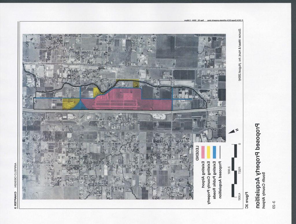
25 CHAPTER 3 AIRFIELD DESIGN PROPERTY ACQUISITION Historically airports have not acquired sufficient property to prevent development of incompatible uses in their vicinity. For most airports in the San Francisco Bay Area it is too late to rectify this problem. The cost and level of community disruption is too high. At South County Airport it remains possible to acquire sufficient property to protect approaches to the runway and buffer adjacent areas from the effects of airport operations. Figure 3C presents the parcels (totaling approximately 332 acres) that are candidates for fee simple acquisition on the open market should they become available or through the use of eminent domain. Many of these parcels could be leased back to the owners following acquisition. However, the lease period and conditions should be crafted to ensure compatible uses and prevent conflicts with planned airport uses (Public Review Draft) South County Airport Master Plan Report: August 18, 2004
26
27
28 Public Review Draft 4 Building Area Design O VERVIEW The building area of an airport encompasses all of the airport property not devoted to runways, major taxiways, required clear areas, and other airfield-related functions. This chapter examines the factors that affect the siting of future building area facilities at South County Airport and alternative ways of accommodating projected demand. The focus is on providing direction for the appropriate expansion and use of the core building areas of the airport. The various design issues associated with South County Airport are discussed in the sections that follow. The Building Area Plan (Figure 3D) provides a snapshot of the airport at the end of the 20-year planning period. Fixed Base Operator (FBO): A business that provides aviation services other than scheduled passenger service. Commonly, services provided by FBOs include: flight training, aircraft rental, fueling, maintenance, and painting. The principal building area is located west of Runway and backs to Murphy Avenue. All aircraft storage hangars and tiedown spaces, a fuel island, and fixed base operator (FBO) buildings are located within this area. Construction of 100 County-owned hangars (91 T-hangars and 9 box hangars) is currently underway in this area. The Master Plan anticipates aviation-related development on the airport property south of the current building area to accommodate additional aircraft storage hangars, transient parking, and fixed base operator (FBO) facilities. Development in this area would also include a new terminal building, maintenance building and vehicle parking. (Public Review Draft) South County Airport Master Plan Report: August 18,
29 CHAPTER 4 BUILDING AREA DEVELOPMENT Design Factors Many factors influence the planning and, later, the development decisions associated with South County s principal building area. Most of these factors can be grouped under five basic headings: Demand The demand for additional building area facilities at South County Airport is forecast to be significant over the next 20-year planning period. As documented in Chapter 2, the number of based aircraft is anticipated to increase to 418. Citation Encore Taxiway A defined path, from one part of an airport to another, selected or prepared for the taxiing of aircraft. Taxilane The portion of the aircraft parking area used for access between taxiways, aircraft parking positions, hangars, fixed base operators, etc. The types of aircraft currently based at South County Airport are primarily single-engine and piston-powered aircraft. It is anticipated that this type of aircraft will continue to be the most prevalent users of the airport. Increased use by turboprops and small to mid-sized corporate jets is also anticipated over the forecast period. Small to mid-sized corporate jets, in this context, means those weighing between 20,000 pounds and 35,000 pounds. The airport s critical aircraft, the Citation Encore, and the larger Hawker 800XP are examples of these types of aircraft. Demand for aircraft storage facilities will be market driven and therefore the timing of development is uncertain. It is anticipated that most of the demand for aircraft storage will be met by the Fixed Base Operators (FBO) on their leaseholds, but some of the demand for additional hangars may be met by the County if warranted by market conditions and consistent with the Business Plan for the airport. Setback Distances The interior boundary of the airport building area is determined in large part by the required setbacks from the nearest runway and taxiways. Based upon design criteria discussed in the preceding chapter, the following design criteria are recommended: A minimum of 445 feet from the centerline of Runway to buildings located on either side of the runway. A minimum of 66 feet from the centerline of taxiways to fixed or movable objects. A minimum of 100 feet between facing medium box hangars (60 foot depth). A minimum of 70 feet between facing T-hangars or small box hangar (50 foot depth). Existing Facilities With the exception of the County hangar project currently under construction, all existing airport 4-2 (Public Review Draft) South County Airport Master Plan Report: August 18, 2004
30 BUILDING AREA DEVELOPMENT CHAPTER 4 facilities are concentrated in the northern quadrant of the airport and provided by the sole FBO. Buildings located within the FBO area are capable of continued use throughout the 20- year time horizon of this plan. Most of the central apron will continue in its present role. Some reconfiguration will be needed to accommodate the pattern of building in adjacent areas. Accessibility An important design consideration is the ease of access to individual portions of the building areas from both the taxiway system and public roads. At South County Airport, parallel Taxiway E provides access to the core building area. Taxiway E does not accommodate ARC B-II aircraft in its present alignment; the required wingtip clearance from existing buildings is insufficient. Taxiway E will need to be realigned west of Taxiway A to provide the required setback for ARC B- II. It is also recommended that Taxiway A and E be extended when Runway 32 is extended further south. As the volume of operations grows, two parallel taxiways will be needed to accommodate the flow of arriving and departing aircraft. Vehicle access to the airport is from two entrances from Murphy Avenue. The first access point is located at the entrance to the existing FBO. The other is located midfield and connects from Murphy Avenue to the main apron. Access to new development in the southwest quadrant of the airport would be provided from Murphy Avenue. This central access point will provide access to hangars in the central section of the building area, as well as based and transient tiedowns. New FBOs will have entrances that connect directly to Murphy Avenue. Development Staging Another important factor in the preparation of a building area plan is the timing of future development. The object is to have a plan that is cost-effective and flexible enough to adapt to changes in the type and pace of facility demand. The linear configuration of the remaining developable area makes it simple for future County and private development to proceed independently. The ability to access Murphy Avenue along the entire perimeter adds to the flexibility. (Public Review Draft) South County Airport Master Plan Report: August 18,

31 CHAPTER 4 BUILDING AREA DEVELOPMENT P RINCIPAL B UILDING A REA F EATURES Aircraft Storage and Parking Pursuant to Chapter 2, Roles & Forecasts, which included demand forecasts for aircraft basing capacity at the three County airports and recommendations relating to the role and basing capacity to be assigned to each airport, South County Airport can be expected to accommodate 418 based aircraft by the year Therefore, the Building Area Plan provides for sufficient County-owned and FBOowned hangars and tiedowns for this number of based aircraft. Hangars Collectively, there are 155 hangars located within the north-side building area, 55 of which are owned by the FBO on its leasehold. The 100 County-owned hangars under construction south of the FBO area comprise the balance. About 36 box hangars (60-foot square) can be accommodated immediately south of the new Countyowned hangars and additional hangars can be accommodated on areas designated for new FBO leaseholds. Tiedowns Approximately 35 tiedowns are provided by the existing FBO. Ninety County-owned tiedown spaces are located on the main apron located west of Runway 32. However, due to weak demand, most of the existing tiedown area is being used for temporary storage of modular buildings in order to generate revenue. The proposed redesign of this central apron will provide 42 tiedowns and parking for up to eight transient business aircraft. Fixed Base Operators Fixed base operators (FBOs) constitute the commercial side of general aviation business. They may provide a wide variety of facilities and services (e.g., aircraft rental and charter, flight instruction, aircraft fueling, and based aircraft hangar and tiedown space rental) for pilots and their aircraft. Busy airports usually have multiple FBOs, while smaller ones may have only one or none. The primary FBO at an airport commonly offers many of these facilities and services; specialized FBOs may supply just one. South County Airport currently has one FBO, located in the north building area. The FBO provides flight training, fuel, aircraft parking 4-4 (Public Review Draft) South County Airport Master Plan Report: August 18, 2004
OVERVIEW BASIC DESIGN FACTORS. Demand Determinants
 3 Airfield Airfield Design Design OVERVIEW The basic configuration of the runway and taxiway system at Hanford Municipal Airport has changed moderately since the airport was constructed in 1950. These
FACILITY REQUIREMENTS SUMMARY OF KEY ISSUES OVERVIEW
 FACILITY REQUIREMENTS SUMMARY OF KEY ISSUES OVERVIEW This summary is intended to provide a brief overview of the key issues associated with conformance to FAA standards at Methow Valley State Airport.
Airfield Design OVERVIEW BASIC DESIGN FACTORS. Airport Role
 3 Airfield Design OVERVIEW Due to the presence of significant physical constraints, little change to the existing airfield is anticipated. The emphasis in this plan is on identifying airfield improvements
Basic Design Factors. Airfield Design. Airport Role
 Chapter 3 Airfield Design Basic Design Factors The Federal Aviation Administration (FAA) provides guidance and standards for airport design through a series of Advisory Circulars (ACs). These guidelines
DRAFT MASTER PLAN UPDATE
 DRAFT MASTER PLAN UPDATE CHAPTER VI: AIRPORT LAYOUT PLAN NARRATIVE DRAFT REPORT APRIL 2017 PREPARED BY: Table of Contents WESTCHESTER COUNTY AIRPORT 6 AIRPORT LAYOUT PLAN NARRATIVE REPORT... 6-1 6.1 AGIS
Chapter 4 Airport Facility Requirements
 Chapter 4 Airport Facility Requirements Introduction CHAPTER 4 AIRPORT FACILITY REQUIREMENTS MAY 2013-1 Organization of Materials CHAPTER 4 AIRPORT FACILITY REQUIREMENTS MAY 2013-2 RPZ - ROAD RPZ - NON-AIRPORT
MASTER PLAN CONCEPT 1 DRAFT
 The Airport Master Plan Update for Dallas Executive Airport has included the development of aviation demand forecasts, an assessment of future facility needs, and the evaluation of airport development
CHAPTER 1 BACKGROUND AND PROPOSED ACTION
 CHAPTER 1 BACKGROUND AND PROPOSED ACTION 1.0 INTRODUCTION An Environmental Assessment (EA) evaluates the effects of a proposed Federal action on the surrounding environment and is prepared in compliance
AIRSIDE CAPACITY AND FACILITY REQUIREMENTS
 AIRSIDE CAPACITY AND FACILITY REQUIREMENTS This Section investigates the capacity of the airport, its ability to meet current demand, and the facilities required to meet forecasted needs as established
Addendum - Airport Development Alternatives (Chapter 6)
") Bowers Field Addendum - Airport Development Alternatives (Chapter 6) This addendum to the Airport Development Alternatives chapter includes the preferred airside development alternative and the preliminary
Bowers Field Addendum - Airport Development Alternatives (Chapter 6) This addendum to the Airport Development Alternatives chapter includes the preferred airside development alternative and the preliminary
Lopez Island Airport Master Plan Update. Public Meeting June 15, 2017
 Lopez Island Airport Master Plan Update Public Meeting June 15, 2017 Master Plan Update Team Reid Middleton/Everett, WA Shannon Kinsella, Project Manager Melania Haagsma, Project Engineer Mead & Hunt/Tulsa,
CHAPTER 3 ALTERNATIVES CONSIDERED
 CHAPTER 3 ALTERNATIVES CONSIDERED 3.0 ALTERNATIVES The 2010 Stevensville Airport Master Plan contained five (5) airside development options designed to meet projected demands. Each of the options from
Source: Chippewa Valley Regional Airport ASOS, Period of Record
 Chapter 1 Inventory Runway wind coverage is the percentage of time a runway can be used without exceeding allowable crosswind velocities. Allowable crosswind velocities vary depending on aircraft size
FACILITY REQUIREMENTS 5.1 Introduction
 Chapter 5 FACILITY REQUIREMENTS 5.1 Introduction The facility requirements section of this study defines the physical facilities needed to safely and efficiently accommodate the current and future aviation
1 DRAFT. General Aviation Terminal Services Aircraft Hangars Aircraft Parking Aprons Airport Support Facilities
 To properly plan for improvements at Dallas Executive Airport, it is necessary to translate forecast aviation demand into the specific types and quantities of facilities that can adequately serve the demand.
1.1.3 Taxiways. Figure 1-15: Taxiway Data. DRAFT Inventory TYPICAL PAVEMENT CROSS-SECTION LIGHTING TYPE LENGTH (FEET) WIDTH (FEET) LIGHTING CONDITION
 WIDTH (FEET) LIGHTING CONDITION") 1.1.3 Taxiways EWN has an extensive network of taxiways and taxilanes connecting the terminal, air cargo, and general aviation areas with the runways as listed in Figure 1-15. A 50-foot wide parallel taxiway
1.1.3 Taxiways EWN has an extensive network of taxiways and taxilanes connecting the terminal, air cargo, and general aviation areas with the runways as listed in Figure 1-15. A 50-foot wide parallel taxiway
Tallahassee International Airport Master Plan. Technical Advisory Committee Meeting #2 October 19, 2016
 Tallahassee International Airport Master Plan Technical Advisory Committee Meeting #2 October 19, 2016 Agenda Welcome / Introductions Master Plan Process and Project Status Forecast of Aviation Demand
Agenda: SASP SAC Meeting 3
 Agenda: SASP SAC Meeting 3 Date: 04/12/18 Public Involvement Plan Update Defining the System Recommended Classifications Discussion Break Review current system Outreach what we heard Proposed changes Classification
According to FAA Advisory Circular 150/5060-5, Airport Capacity and Delay, the elements that affect airfield capacity include:
 4.1 INTRODUCTION The previous chapters have described the existing facilities and provided planning guidelines as well as a forecast of demand for aviation activity at North Perry Airport. The demand/capacity
Appendix C AIRPORT LAYOUT PLANS
 Appendix C AIRPORT LAYOUT PLANS Appendix C AIRPORT LAYOUT PLANS Airport Master Plan Santa Barbara Airport As part of this Airport Master Plan, the Federal Aviation Administration (FAA) requires the development
Yolo County Airport. ALP Narrative Report. April Prepared by Mead & Hunt, Inc. for the County of Yolo, California
 Yolo County Airport ALP Narrative Report April 2016 Prepared by Mead & Hunt, Inc. for the County of Yolo, California Yolo County Airport ALP Narrative Report Prepared for the County of Yolo Mindi Nunes,
Preliminary Findings of Proposed Alternative
 Preliminary Findings of Proposed Alternative The attached drawing provides a schematic layout of the proposed alternative that will be discussed on July 27, 2010. A full report will follow and should be
CHAPTER 3 FACILITY REQUIREMENTS
 CHAPTER 3 FACILITY REQUIREMENTS 3.1 INTRODUCTION To properly plan for the future requirements of Newport News/Williamsburg International Airport, it is necessary to translate the forecasts of aviation
PORT OF PORTLAND. Chapter Four AVIATION FACILITY REQUIREMENTS
 PORT OF PORTLAND Chapter Four AVIATION FACILITY REQUIREMENTS CHAPTER FOUR PORT OF PORTLAND AVIATION FACILITY REQUIREMENTS In this chapter, existing components of the airport are evaluated to identify the
The purpose of this Demand/Capacity. The airfield configuration for SPG. Methods for determining airport AIRPORT DEMAND CAPACITY. Runway Configuration
 Chapter 4 Page 65 AIRPORT DEMAND CAPACITY The purpose of this Demand/Capacity Analysis is to examine the capability of the Albert Whitted Airport (SPG) to meet the needs of its users. In doing so, this
FORT LAUDERDALE-HOLLYWOOD INTERNATIONAL AIRPORT ENVIRONMENTAL IMPACT STATEMENT DRAFT
 D.3 RUNWAY LENGTH ANALYSIS Appendix D Purpose and Need THIS PAGE INTENTIONALLY LEFT BLANK Appendix D Purpose and Need APPENDIX D.3 AIRFIELD GEOMETRIC REQUIREMENTS This information provided in this appendix
New Opportunities PUBLIC WORKSHOP. Venice Municipal. Bringing g the pieces together
 Bringing g the PUBLIC WORKSHOP Venice Municipal Airport New Opportunities Presented for Venice City Council & Citizens of Venice September 25, 2009 Slide 1 Bringing g the Welcome & Introductions May 12th
CHAPTER 3 AIRPORT FACILITY REQUIREMENTS
 CHAPTER 3 AIRPORT FACILITY REQUIREMENTS 3.1 Introduction The existing runway and taxiway system at Skyhaven Airport provides more than adequate operational capacity to accommodate future peak hour and
Runway Length Analysis Prescott Municipal Airport
 APPENDIX 2 Runway Length Analysis Prescott Municipal Airport May 11, 2009 Version 2 (draft) Table of Contents Introduction... 1-1 Section 1 Purpose & Need... 1-2 Section 2 Design Standards...1-3 Section
Hartford-Brainard Airport Potential Runway Closure White Paper
 Hartford-Brainard Airport Potential Runway 11-29 Closure White Paper June 2012 In recent years there has been discussion regarding the necessity of Runway 11-29 to the Hartford- Brainard Airport (HFD)
Appendix D Project Newsletters. Tacoma Narrows Airport. Master Plan Update
 Appendix D Project Newsletters Tacoma Narrows Airport Master Plan Update This appendix contains the newsletters distributed throughout the project. These newsletters provided updates and information on
Chapter 5. Facility Requirements
 Chapter 5 Facility Requirements Chapter 5 Facility Requirements INTRODUCTION The Baseline Forecast was used to determine facility requirements. Chapter 4 produced a forecast of traffic volumes expected
3 INTRODUCTION. Chapter Three Facility Requirements. Facility Requirements PEAKING CHARACTERISTICS
 Chapter Three Facility Requirements 3 INTRODUCTION This chapter identifies the long-range airfield and terminal area facilities needed to satisfy the 20-year forecast of aviation demand at Monett Municipal
chapter 5 Recommended Master Plan Concept airport master plan MASTER PLAN CONCEPT
 chapter 5 Recommended Master Plan Concept airport master plan The planning process for Coolidge Municipal Airport has included several analytical efforts in the previous chapters intended to project potential
APPENDIX X: RUNWAY LENGTH ANALYSIS
 APPENDIX X: RUNWAY LENGTH ANALYSIS Purpose For this Airport Master Plan study, the FAA has requested a runway length analysis to be completed to current FAA AC 150/5325-4B, Runway Length Requirements for
Executive Summary. MASTER PLAN UPDATE Fort Collins-Loveland Municipal Airport
 Executive Summary MASTER PLAN UPDATE Fort Collins-Loveland Municipal Airport As a general aviation and commercial service airport, Fort Collins- Loveland Municipal Airport serves as an important niche
The offers operators increased capacity while taking advantage of existing airport infrastructure. aero quarterly qtr_03 10
 The 747 8 offers operators increased capacity while taking advantage of existing airport infrastructure. 14 aero quarterly qtr_03 10 Operating the 747 8 at Existing Airports Today s major airports are
C > Capacity Analysis and Facility Requirements
 Buchanan Field Buchanan Field Airport Master Planning Program C. CAPACITY ANALYSIS & FACILITY REQUIREMENTS C > Capacity Analysis and Facility Requirements INTRODUCTION. The capacity of an airfield is primarily
CHAPTER 1 EXECUTIVE SUMMARY
 CHAPTER 1 EXECUTIVE SUMMARY 1 1 EXECUTIVE SUMMARY INTRODUCTION William R. Fairchild International Airport (CLM) is located approximately three miles west of the city of Port Angeles, Washington. The airport
Chapter Six ALP Drawings. Tacoma Narrows Airport. Master Plan Update
 Chapter Six ALP Drawings Master Plan Update The master planning process for the (Airport) has evolved through efforts in the previous chapters to analyze future aviation demand, establish airside and landside
Chapter 4 Airport Facility Requirements
 Chapter 4 Airport Facility Requirements The evaluation of airport facility requirements uses the results of the inventory and forecasts contained in Chapters Two and Three, as well as established planning
Appendix B Ultimate Airport Capacity and Delay Simulation Modeling Analysis
 Appendix B ULTIMATE AIRPORT CAPACITY & DELAY SIMULATION MODELING ANALYSIS B TABLE OF CONTENTS EXHIBITS TABLES B.1 Introduction... 1 B.2 Simulation Modeling Assumption and Methodology... 4 B.2.1 Runway
Grants Pass Airport Master Plan & Airport Layout Plan Update
 Attendees: Grants Pass Airport Master Plan & Airport Layout Plan Update Meeting #3 January 26, 2010 Merlin Community Center 100 Acorn Street, Merlin 5:45 7:15 p.m. Josephine County Department of Airports:
Technical Memorandum. Synopsis. Steve Carrillo, PE. Bryan Oscarson/Carmen Au Lindgren, PE. April 3, 2018 (Revised)
") Appendix D Orange County/John Wayne Airport (JWA) General Aviation Improvement Program (GAIP) Based Aircraft Parking Capacity Analysis and General Aviation Constrained Forecasts Technical Memorandum To:
Appendix D Orange County/John Wayne Airport (JWA) General Aviation Improvement Program (GAIP) Based Aircraft Parking Capacity Analysis and General Aviation Constrained Forecasts Technical Memorandum To:
1) Rescind the MOD (must meet the standard); 2) Issue a new MOD which reaffirms the intent of the previous MOD; 3) Issue a new MOD with revisions.
 Rescind the MOD (must meet the standard); 2) Issue a new MOD which reaffirms the intent of the previous MOD; 3) Issue a new MOD with revisions.") ALBUQUERQUE INTERNATIONAL SUNPORT AIRCRAFT HOLD LINE LOCATION ANALYSIS WHITE PAPER JUNE 24, 2016 HOLD LINE LOCATION ISSUE The location of many of the taxiway hold lines at the Sunport do not meet current
ALBUQUERQUE INTERNATIONAL SUNPORT AIRCRAFT HOLD LINE LOCATION ANALYSIS WHITE PAPER JUNE 24, 2016 HOLD LINE LOCATION ISSUE The location of many of the taxiway hold lines at the Sunport do not meet current
5. Facility Requirements
 5. Facility Requirements The purpose of this chapter is to compare existing airfield and adjacent landside facilities with the Airport operations and aircraft forecasts developed in the previous chapter
Chapter Three AIRPORT FACILITY REQUIREMENTS/ALTERNATIVES
 Chapter Three AIRPORT FACILITY REQUIREMENTS/ALTERNATIVES Airport Layout Plan Report In this chapter, existing components of the Airport are evaluated so that the capacities of the overall system are identified.
Chapter 4 AIRPORT DEVELOPMENT ALTERNATIVES
 Chapter 4 AIRPORT DEVELOPMENT ALTERNATIVES Chapter Four Airport Development Alternatives Prior to formulating a development program for Ryan Airfield, it is important to consider development potential
Chapter 3 FACILITY REQUIREMENTS
 Chapter 3 FACILITY REQUIREMENTS Chapter Three Facility Requirements To properly plan for the future of Ryan Airfield, it is necessary to translate forecast aviation demand into the specific types and quantities
Safety, Infrastructure, and Tenant Improvement Project. Public Hearing Informational Brochure February 26, 2013
 New York State Department of Transportation Safety, Infrastructure, and Tenant Improvement Project Public Hearing Informational Brochure February 26, 2013 This DEIS/Draft EA evaluates the potential impacts
Chapter 4 Airport Facility Requirements. Introduction
 Chapter 4 Airport Facility Requirements Introduction The airport facility requirements analysis combines the results of the inventory and forecasts contained in Chapters Two and Three, and the applicable
Chapter 4.0 Alternatives Analysis
 Chapter 4.0 Alternatives Analysis Chapter 1 accumulated the baseline of existing airport data, Chapter 2 presented the outlook for the future in terms of operational activity, Chapter 3 defined the facilities
Chapter 5 Facility Requirements
 Chapter 5 Facility Requirements 5.0 INTRODUCTION The Facility Requirements chapter of this Sustainable Master Plan Update describes airside and landside facilities, which are needed to accommodate existing
CATCODE ] CATCODE
![CATCODE ] CATCODE](/thumbs/82/85644630.jpg "CATCODE ] CATCODE") Runways. FAC: 1111 CATCODE: 111111 OPR: AFCEC/COS OCR: AF/A3O-A 1.1. Description. The runway is the paved surface provided for normal aircraft landings and take offs. Runways are classified as either Class
Runways. FAC: 1111 CATCODE: 111111 OPR: AFCEC/COS OCR: AF/A3O-A 1.1. Description. The runway is the paved surface provided for normal aircraft landings and take offs. Runways are classified as either Class
Facility Requirements
 C H A P T E R T H R E E Facility Requirements 3.0 OVERVIEW Airport planning for facility requirements is based upon addressing any existing issues and accommodating the probable demand that may occur over
4.0 AIRFIELD CAPACITY & FACILITY REQUIREMENTS
 4.0 AIRFIELD CAPACITY & FACILITY REQUIREMENTS A key step in the Airport Master Plan (AMP) process is determining future requirements for airport facilities that will allow for airside and landside development
RECOMMENDED MASTER PLAN CONCEPT
 RECOMMENDED MASTER PLAN CONCEPT Chapter Five The airport master planning process for Salina Regional Airport (SLN) has progressed through a systematic and logical process with a goal of formulating a recommended
PLU Airport Master Plan. Master Plan Advisory Committee (MPAC) Meeting #4 March 19, 2018
 Meeting #4 March 19, 2018") PLU Airport Master Plan Master Plan Advisory Committee (MPAC) Meeting #4 March 19, 2018 Meeting Agenda 1. Master Plan Status [5 Minutes] 2. Preferred Forecasts [15 Minutes] 3. Runway Length Options [45
PLU Airport Master Plan Master Plan Advisory Committee (MPAC) Meeting #4 March 19, 2018 Meeting Agenda 1. Master Plan Status [5 Minutes] 2. Preferred Forecasts [15 Minutes] 3. Runway Length Options [45
AIRPORT FACILITY REQUIREMENTS
 4.1 INTRODUCTION Chapter 4 AIRPORT FACILITY REQUIREMENTS The major elements of the Airport, which were described in Chapter 3, Existing Airport Facilities must be analyzed individually and balanced in
Draft Concept Alternatives Analysis for the Inaugural Airport Program September 2005
 Draft Concept Alternatives Analysis for the Inaugural Airport Program September 2005 Section 3 - Refinement of the Ultimate Airfield Concept Using the Base Concept identified in Section 2, IDOT re-examined
CHAPTER 1 INTRODUCTION AND BACKGROUND
 CHAPTER 1 INTRODUCTION AND BACKGROUND An Environmental Assessment (EA) evaluates the effects of a proposed Federal action on the surrounding environment and is prepared in compliance with the National
The following criteria shall be applied within the boundaries of the AO District:
 Sec. 419 (a) Purpose AIRPORT OVERLAY DISTRICT (AO) The purpose of the Airport Overlay District is to regulate and restrict the height of structures, objects, or natural growth, regulate the locations of
Dallas Executive Airport
 648 DECLARED DISTANCE OPTION 1a DISPLACE 31 THRESHOLD BY 97 Considers RSA Limiting Factor No runway extensions 13 31 TORA 6,451 6,451 TODA 6,451 6,451 ASDA 5,958 6,451 LDA 5,958 6,354 Runway 17-35 (3,8
Chapter 5 Facility Requirements
 Chapter 5 Facility Requirements 50 INTRODUCTION This chapter describes the airside and landside facility requirements necessary to accommodate existing and forecasted demand in accordance with Federal
Technical Advisory Committee Meeting February 29, 2016
 Technical Advisory Committee Meeting February 29, 2016 Meeting Agenda Introduction Recap of Planning Process Project Status Goals and Objectives Forecasts of Aviation Demand Overview of Facility Requirements
Table of Contents. List of Tables. Cincinnati/Northern Kentucky International Airport 2035 Master Plan Update
 Table of Contents 7.1. Airport Layout Plan (Existing Conditions)... 2 7.2. Airport Layout Plan (Future Conditions)... 3 7.3. Technical Data Sheet... 5 7.4. Commercial Terminal Area Drawing... 5 7.5. East
4. Demand/Capacity Assessment and Facility Requirements
 4. This chapter presents an evaluation of the existing airfield facilities, buildings, and other facilities at the Airport and an assessment of their potential use under the demand scenarios defined for
Chapter 4 Airport Capacity Assessment and Identification of Facility Needs
 Chapter 4 Airport Capacity Assessment and Identification of Facility Needs 4.1 Introduction The purpose of the airport capacity assessment and identification of facility needs is to evaluate the single
Flying Cloud Airport (FCM) Zoning Process: Informing a Mn/DOT Path Forward
 Zoning Process: Informing a Mn/DOT Path Forward") : Informing a Mn/DOT Path Forward A Review of the Flying Cloud Airport (FCM) Joint Airport Zoning Board (JAZB) Process and the Draft Airport Zoning Ordinance B A RPZ RPZ A B C Zone Chad E. Leqve Director
: Informing a Mn/DOT Path Forward A Review of the Flying Cloud Airport (FCM) Joint Airport Zoning Board (JAZB) Process and the Draft Airport Zoning Ordinance B A RPZ RPZ A B C Zone Chad E. Leqve Director
DEPARTMENT: CIVIL ENGINEERING SEMESTER: III SUBJECT CODE / Name: CE2303/ Railway, Airport and Harbors Engineering 2 MARK QUESTIONS AND ANSWERS
 DEPARTMENT: CIVIL ENGINEERING SEMESTER: III SUBJECT CODE / Name: CE2303/ Railway, Airport and Harbors Engineering 2 MARK QUESTIONS AND ANSWERS 1.Define wind Coverage (AUC NOV/DEC 2010),(AUC NOV/DEC 2011)
Thursday, May 2 nd, 2013 South St. Paul Municipal Airport Meeting Room 4:00 p.m. 5:30 p.m. MEETING NOTES
 SOUTH ST. PAUL MUNICIPAL AIRPORT FLEMING FIELD MASTER PLAN ADVISORY GROUP MEETING #2 Thursday, May 2 nd, 2013 South St. Paul Municipal Airport Meeting Room 4:00 p.m. 5:30 p.m. MEETING NOTES The purpose
6.1 INTRODUCTION 6.2 AIRSIDE ALTERNATIVES NORTH PERRY AIRPORT MASTER PLAN UPDATE RUNWAY LENGTH REQUIREMENTS SECTION 6: ALTERNATIVES ANALYSIS
 6.1 INTRODUCTION In the previous chapter, facility needs for the 20-year planning horizon were identified. The next step in the planning process is to identify and evaluate the various ways certain facilities
Facility Requirements
 4. This chapter presents the airside and landside facility requirements necessary to accommodate existing and forecasted demand at Erie International Airport (ERI or the Airport) in accordance with Federal
2015 PURDUE ROAD SCHOOL March 11, 2015
 2015 PURDUE ROAD SCHOOL March 11, 2015 Runway Protection Zone (RPZ) Definition It is a trapezoidal shape formed off the end of a runway and its geometry it a function of the airport s aircraft approach
STAFF REPORT. Airport Land Use Plan Consistency Review: Santa Barbara Airport Master Plan. MEETING DATE: November 19, 2015 AGENDA ITEM: 7D
 STAFF REPORT SUBJECT: Airport Land Use Plan Consistency Review: Santa Barbara Airport Master Plan MEETING DATE: AGENDA ITEM: 7D STAFF CONTACT: Peter Imhof, Andrew Orfila RECOMMENDATION: Adopt findings
Table of Contents. Overview Objectives Key Issues Process...1-3
 Table of Contents Chapter One Introduction Overview...1-1 Objectives...1-1 Key Issues...1-2 Process...1-3 Chapter Two Inventory of Existing Conditions Airport Setting...2-1 Locale...2-1 Airport Surroundings...2-5
Lake Tahoe Airport Master Plan Public Meeting March 16, 2015
 Lake Tahoe Airport Master Plan Public Meeting March 16, 2015 What is an Airport Master Plan? a comprehensive study of an airport [that] usually describes the short, medium, and long term development plans
Demand. Typical Building Area Functions and Facilities Commonly Found at General Aviation Airports:
 OVERVIEW The building area of an airport encompasses all of the airport property not devoted to runways, major taxiways, required clear areas, and other airfieldrelated functions. Typical facilities found
Appendix D August 2001 RUNWAY SAFETY Revised March 2002 AREA DETERMINATION RUNWAY 17-35
 Appendix D August 2001 RUNWAY SAFETY Revised March 2002 AREA DETERMINATION Master Plan Update RUNWAY 17-35 Hector International Airport SUFFICIENCY ANALYSIS Near the completion of the Master Plan Update
CHAPTER 5 - FACILITY REQUIREMENTS
 CHAPTER 5 - FACILITY REQUIREMENTS This chapter identifies the requirements for airfield and landside facilities to accommodate the forecast demand level. Facility requirements have been developed for the
15 Precision Approach Path Indicator 33 None RSA 150 feet wide by 300 feet long 150 feet wide by 300 feet long
 The first (AMP) was completed in 1984 and updated in 2000. The current FAA approved Airport Layout Plan (ALP) is dated November 9, 2001. The FAA suggests updating the AMP every five year in accordance
Chapter 9 - AIRPORT SYSTEM DESIGN
 Chapter 9 - AIRPORT SYSTEM DESIGN 9.01 GENERAL This chapter discusses the development program for Dutchess County Airport to the year 2020. This airport system design is based upon the airport's existing
CHAPTER D Capacity Analysis and Facility Requirements INTRODUCTION
 CHAPTER D Capacity Analysis and Facility Requirements INTRODUCTION The capacity of an airfield is primarily a function of the major aircraft operating surfaces that compose the facility and the configuration
BELFAST MUNICIPAL AIRPORT OVERVIEW
 BELFAST MUNICIPAL AIRPORT OVERVIEW LOCATION AND HISTORY Belfast Municipal Airport (Federal Aviation Administration (FAA) airport code BST, International Civil Aviation Organization airport code KBST, FAA
Draft Concept Alternatives Analysis for the Inaugural Airport Program September 2005
 Section 10 Preferred Inaugural Airport Concept 10.0 Introduction The Preferred Inaugural Airport Concept for SSA was developed by adding the preferred support/ancillary facilities selected in Section 9
Chapter 4 Facility Requirements
 Chapter 4 Facility Requirements Introduction This chapter evaluates the existing airport facilities and identifies improvements needed to effectively meet the forecasted demand levels discussed in the
AIRFIELD CAPACITY AND FACILITY REQUIREMENTS
 CHAPTER FOUR: AIRFIELD CAPACITY AND FACILITY REQUIREMENTS 4.1 INTRODUCTION A key step in the Airport Master Plan Update (AMPU) process is determining future requirements for airport facilities that will
5.0 ALTERNATIVES ANALYSIS
 5.0 ALTERNATIVES ANALYSIS The Alternative Analysis chapter describes and evaluates the various development alternatives considered for. In addition, it presents a preferred development plan that accommodates
CHAPTER 1: INTRODUCTION
 CHAPTER 1: INTRODUCTION Purpose and Scope The information presented in this report represents the study findings for the 2016 Ronan Airport Master Plan prepared for the City of Ronan and Lake County, the
Dr. Antonio A. Trani Professor of Civil Engineering Virginia Polytechnic Institute and State University. Spring 2015 Blacksburg, Virginia
 CEE 4674 Airport Planning and Design Runway Length Calculations Addendum 1 Dr. Antonio A. Trani Professor of Civil Engineering Virginia Polytechnic Institute and State University Spring 2015 Blacksburg,
Document prepared by MnDOT Office of Aeronautics and HNTB Corporation. MINNESOTA GO STATE AVIATION SYSTEM PLAN
 LAST UPDATE JULY 2013 Acknowledgements The preparation of this document was financed in part by a grant from the Federal Aviation Administration (Project No: 3-27-0000-07-10), with the financial support
Airport Obstruction Standards
 Airport Obstruction Standards Dr. Antonio Trani Department of Civil and Environmental Engineering Virginia Tech Outline of this Presentation Obstructions to navigation around airports Discussion of Federal
Boeing Airplane Overview
 Boeing Airplane Overview Yonglian Ding, PE Boeing Airport Compatibility Engineering Nov 29, 2016 BOEING is a trademark of Boeing Management Company. Copyright 2016 Boeing. All rights reserved. Agenda Aircraft
4.0 FACILITY REQUIREMENTS
 4.0 FACILITY REQUIREMENTS The purpose of this chapter of Master Plan is to identify the needs for additional facilities, or improvements to existing facilities over the planning period. By comparing current
Chapter 5 Facility Requirements
 Chapter 5 Facility Requirements Chapter 5 Facility Requirements INTRODUCTION Chapter 4 produced a forecast of traffic volumes estimated to be generated at the airport during the 20- year forecast period.
Notice of Extended Comment Period for an Intent to Adopt a Negative Declaration
 County of Santa Clara Department of Planning and Development Planning Office County Government Center, East Wing, 7 th Floor 70 West Hedding Street San Jose, California 95110-1705 (408) 299-5770 FAX (408)
Appendix 6.1: Hazard Worksheet
 Appendix 6.1: Appendix 6.1: Ref. Condition, real or potential; that can cause injury, illness, etc. This is a prerequisite for an Airfield Hazards 1. Taxiway Geometry Direct access to runway from ramp
SECTION 5 ALTERNATIVE DEVELOPMENT CONCEPT ANALYSES
 SECTION 5 ALTERNATIVE DEVELOPMENT CONCEPT ANALYSES 5.1 INTRODUCTION This section investigates Airfield Development Alternatives, generalized Land Use Alternatives, and more detailed General Aviation Alternatives.
AIRPORT FACILITY REQUIREMENTS
 4 AIRPORT FACILITY REQUIREMENTS AIRPORT DESIGN FACTORS This chapter identifies the long-range airfield and terminal area facilities needed to satisfy the 20-year forecast of aviation demand at the Bowers
Chapter 4.0 Facility Requirements
 Chapter 4.0 Facility Requirements Having inventoried the existing infrastructure and forecasted demand, determining airport facility requirements is the next essential step in the airport master planning