AIRPORT LAYOUT PLAN FUTURE LEGEND: REVISIONS BUILDING AIRPORT PROPERTY RUNWAY PROTECTION ZONE (RPZ) AIRCRAFT PAVEMENT
|
|
|
- Bruce Armstrong
- 5 years ago
- Views:
Transcription


 was prepared for the Storm Lake Municipal Airport")


: 1,488' 1,488' AIRPORT REFERENCE POINT (ARP) LATITUDE 42 ' 50.")
1 AIRPORT LAYOUT PLAN STORM LAKE MUNICIPAL AIRPORT (SLB) KNOTS FAA APPROVAL LETTER STORM LAKE, IA STORM LAKE MUNICIPAL AIRPORT $ LOCATION MAP $ ALL WEATHER WINDROSE STORM LAKE MUNICIPAL AIRPORT US Department of Transportation Federal Aviation Administration, AeroNav Products Copyright: 2013 National Geographic Society, i-cubed INDEX TO S 1. TITLE 2. AIRPORT LAYOUT PLAN 3. FAR PART 77 IMAGINARY SURFACES 4. & RUNWAY APPROACH PLAN & PRILE 5. & RUNWAY APPROACH PLAN & PRILE. & RUNWAY 13 APPROACH PLAN & PRILE 7. & RUNWAY APPROACH PLAN & PRILE 8. & RUNWAY / APPROACH PLAN & PRILE 9. & BUILDING AREA PLAN 10. LAND USE & ZONING. EXHIBIT A AIRPORT INVENTORY MAP BUENA VISTA COUNTY, IA SPONSOR APPROVAL STORM LAKE, IOWA APPROVED BY: DATE: TITLE On behalf of Bolton & Menk, Inc. this Airport Layout Plan (ALP) was prepared for the Storm Lake Municipal Airport according to the applicable Advisory Circulars, the current version of the ARP SOP 2.00 ALP Checklist, and accurately depicts the proposed use of airspace at the time of submittal. The ALP conforms with FAA design standards, except as noted. DATE: JAN 20, 2014 MELISSA R. UNDERWOOD FAA APPROVAL STAMP AIRPORT DATA TABLE ALL WEATHER WINDROSE / 13/ / 10.5 KNOTS ALL WEATHER WIND COVERAGE CROSSWINDS RUNWAY / RUNWAY 13/ RUNWAY / COMBINED 10.5 KNOTS INSTRUMENT FLIGHT RULES CROSSWINDS RUNWAY / RUNWAY 13/ RUNWAY / COMBINED 10.5 KNOTS SOURCE: NATIONAL CLIMATIC DATA CENTER FOR STORM LAKE, IA ( ) NPIAS SERVICE LEVEL: GENERAL AVIATION GENERAL AVIATION IA SASP SERVICE ROLE: GENERAL SERVICE GENERAL SERVICE MEAN MAXIMUM TEMPERATURE HOTTEST MONTH: 83 F 83 F AIRPORT ELEVATION (NAVD88): 1,488' 1,488' AIRPORT REFERENCE POINT (ARP) LATITUDE 42 ' 50.05" N 42 ' 44.72" N COORDINATES (NAD 83): LONGITUDE 95 14' 2.40" W 95 14' 25.25" W AIRPORT REFERENCE CODE: B-II B-II AIRPORT NAVAIDS: MISCELLANEOUS FACILITIES: NDB AWOS, MIRL, REILs, PAPIs, WIND CONE SAME INSTRUMENT FLIGHT RULES (IFR) WINDROSE / 13/ / 10.5 KNOTS 10.5 KNOTS KNOTS 10.5 KNOTS PROJECT NO: T DATE: APRIL 18, 201 TITLE DATE: JAN 18, 201

2 OOOOOOOOOOOOOOOOOOOOOOOOOOOOOOOOOOOOOOOOOOOOOOOOOOOOOOOOOOOOOOOOOOOOOOOOOOOOOOOOOOOOOOOOOOOOOOOOOOOOOOOOOOOOOOOOOOOOOOOOOOOOOOOOOOOOOOOOOOO 1,410' 1,410' 1,470' 1,410' IA 0 CH C5 30th ST. 1,390' 1,410' 1,490' 20:1 APPROACH SURFACE EXIST 20:1 APPROACH SURFACE EXIST 20:1 APDS ROW 3 EXIST 40:1 APDS ROW RWY13/ HIGH POINT RWY 13 TDZ LIMIT STA FUT APPROACH RPZ ELEV=1,477.4' EXIST RWY 13 DISPLACED THRESHOLD STA ELEV=1,47.7' FUT RWY TDZ LIMIT STA ELEV=1,475.5' 13 FUT RWY 13 DISPLACED THRESHOLD STA ELEV=1,47.1' RWY / LOW POINT STA ELEV=1,479.' EXIST NDB WIND CONE EXIST PAPI RPZ 250' X X 450' RWY HIGH POINT TDZ LIMITS STA ELEV=1,487.9' EXIST DEPATURE RPZ RWY / HIGH POINT RWY TDZ LIMIT EXIST RWY TDZ LIMIT STA ELEV=1,484.0' EXIST APPROACH RPZ EXIST PAPI OOOOOOOOOOOOOOOOOOOOOOOOOOOOOOOOOOOOOOOOOOOOOOOOOOOOOOOOOOOOOOOOOOOOOOOOOOOOOOOOOOOOOOOOOOOOOOOOOOOOOOOOOOOOOOOOOOO EXIST RWY STA ELEV=1,479.8' FUT RWY STA ELEV=1,479.8' FUT RPZ X 2,500' X EXIST RPZ OOOOOOOOOOOOOOOOOOOOOOOOOOOOOOOOOOOOOOOOOOOOOOOOOOOOOOOOOOOOOOOOOOOOOOOOOOOOOOOOOOOOOOOOOOOOOOOOOOOOOOOOOOOOOOOOOOOOOOOOOOOOOOOOOOOOOOOOOOOOOOOOOOOOOOOOOOOOOOOOOOOOOOOOOOOOOOOOOOOOOOOOOOOOO OOOOOOOOOOOOOOOOOO 800 ' 300 ' 400 ' 500 ' 150 ' 300 ' OOOOOOOOOOOOO OOOOOO O OOOOOOOOOOOOOOOOOOOOOOOOOOOOOOOOOOOOOOOOOOOOOOOOOOOOOOOOOOOOOOOOOOOOOOOOOOOOOOOOO OOOOOOOOOOOOOOOOOOOOOOOOOOOOOOOOOOOOOOOOOOOOOOOOOOOOOOOOOOOOOOOOOOOOOOOOOOOOOOOOOOOOOOOOOOOOOOOOOOOOOOOOOOOOOOOOOOOOOOO OOO ' FUT PARALLEL TAXIWAY RUNWAY 13/ 3,0X50' FUT 3,00'X75' S44 43' 51.38"E BRL 20' BRL 20' RA BRL 20' RA BRL 20' RA RA RZ RZ RUNWAY / 5,002'X75' FUT,500X75' S3 54'.48"E RZ RZ RA RA EXIST 20:1 APDS ROW 3 EXIST 34:1 APPROACH SURFACE RUNWAY / 1,92X95' N 42' 5.49"E ' FUT PARALLEL TAXIWAY EXIST RPZ FUT 50:1 APPROACH SURFACE EXIST 40:1 APDS ROW 500 ' 120 ' OOOOOOOOOOOOOOOOOOOOOOOOOOOOOOOOOOOOOOOOO OOOOOOOOOOOOOOOOOOOOOOOOOOOOOOOO EXIST AWOS CRITICAL AREA FUT RPZ X 2,500' X 250 ' EXIST 34:1 APPROACH SURFACE FUT 50:1 APPROACH SURFACE 150 ' 400 ' 500 ' 0 ' AIRPORT BEACON 100 FUEL PUMPS RPZ 250' X X 450' EXIST RPZ EXIST FUT RWY STA 9+2 ELEV=1,49.9' EXIST RWY STA 230+ ELEV=1,4.7' FUT RWY STA ELEV=1,4.7' FUT RPZ 20:1 APPROACH SURFACE 20:1 APDS ROW 2 20:1 APDS ROW 2 1,390' 1,430' 1,380' 1,390' 1,390' 80th AVE. FUT RWY TDZ LIMIT STA 1+0 ELEV=1,482.0' 50th ST. 1,490' BRL 20' BRL 20' BRL 20' BRL 20' RA RZ EXIST 20:1 APDS ROW 3 BRL 20' BRL BRL 20' BRL 20' BRL 20' BRL 20' BRL 20' BRL 20' RA EXIST 20:1 APDS ROW 3 EXIST RWY 13/ LOW POINT STA 230+ ELEV=1,4.7' FUT RWY 13/ LOW POINT STA ELEV=1,4.7' RZ BRL 20' BRL 20' BRL 20' BRL 20' BRL 20' 20' RZ FUT 40:1 APDS ROW EXIST RWY TDZ LIMIT STA 200+ ELEV=1,477.2' 1,470' EXIST 40:1 APDS ROW 1,440' CH C5 30th ST. RWY / LOW POINT STA 8+2 ELEV=1,49.5' FUT 20:1 APDS ROW 3 CH M43 90th AVE. EXIST 20:1 APPROACH SURFACE FUT 20:1 APPROACH SURFACE 1,40' 1,420' EXIST 40:1 APDS ROW FUT 40:1 APDS ROW 1,440' EXIST 20:1 APDS ROW 3 1,420' 1,40' 1,410' STONEY POINT RD. 1,420' RUNWAY DATA TABLE RUNWAY / RUNWAY LENGTH & WIDTH 5,002' X 75',500' X 75' RUNWAY GRADIENT 0.20 SAME RUNWAY TYPE OTHER-THAN-UTILITY SAME PAVEMENT TYPE CONCRETE SAME PAVEMENT STRENGTH 45,000LBS DWG; 25,000 LBS SWG SAME RUNWAY LIGHTING MIRL SAME RUNWAY MARKING NON-PRECISION SAME 14 CFR PART 77 34:1 50:1/40:1 APPROACH TYPE NON-PRECISION PRECISION RUNWAY DESIGN CODE (RDC)/RUNWAY REFERENCE CODE (RRC) C-II-5000 B-II-5000 RUNWAY NAVAIDS PAPIs, REILs, GPS, NDB SAME TYPE AERONAUTICAL SURVEY VERTICALLY GUIDED SAME VISIBILITY MINIMUMS 1 MILE SAME WIND COVERAGE FAA RUNWAY PROTECTION ZONE (RPZ) DIMENSIONS RUNWAY BASE LENGTH OUTER WIDTH EXIST FUT ' 500' 250' 2,500' 700' 700' 450' 500' 500' 250' 2,500' 700' 700' 450' RUNWAY RUNWAY SAFETY AREA () WIDTH LENGTH BEYOND RUNWAY END / 150' 300' 13/ 150' 300' / 120' 0' RUNWAY WIDTH LENGTH BEYOND RUNWAY END / 300' 00' RUNWAY OBJECT FREE AREA (RA) RUNWAY WIDTH LENGTH BEYOND RUNWAY END / 500' 300' 13/ 500' 300' / 250' 0' RUNWAY WIDTH LENGTH BEYOND RUNWAY END / 800' 00' RUNWAY OBSTACLE FREE ZONE (RZ) & RUNWAY WIDTH LENGTH BEYOND RUNWAY END / 400' 200' 13/ 400' 200' / 250' 200' TERPS DEPARTURE SURFACE RUNWAY BASE LENGTH OUTER WIDTH & / 10,200',4' 13/ 10,200',4' RUNWAY RUNWAY END COORDINATES LATITUDE LONGITUDE 42 3' 3.83" N 95 14'.89" W 42 ' 14.2" N 95 14' 25.9" W ' 12.70" N 95 14' 37.3" W 42 ' 51.85" N 95 14' 8.23" W 42 ' 54.71" N 95 14' 37.45" W 42 3' 2.74" N 95 14' 13.58" W 13 DISPLACED THRESHOLD 42 3'.57" N 95 14'.78" W RUNWAY LATITUDE LONGITUDE 42 34' 59.87" N 95 14'.19" W 42 ' 47.9" N 95 14' 2.80" W 13 DISPLACED THRESHOLD 42 3' 10.12" N 95 14' 33.7" W RUNWAY END STATION AND ELEVATION RUNWAY STATION ELEVATION ,479.' ,479.8' ,477.4' ,4.7' ,487.9' 9+2 1,49.9' 13 DISPLACED THRESHOLD ,47.7' RUNWAY STATION ELEVATION ,479.8' ,4.7' 13 DISPLACED THRESHOLD ,47.1' TOUCHDOWN ZONE (TDZ) LIMITS RUNWAY TDZ LIMITS STATION LOCATION ELEVATION TO ,484.0' TO ,484.0' TO ,477.2' 230+ TO ,477.2' TO ,49.9' 9+2 TO ,49.9' TO ,482.0' TO ,475.5' AIRPORT REFERENCE POINT (ARP) LATITUDE 42 ' 50.05" N 42 ' 44.72" N LONGITUDE 95 14' 2.40" W 95 14' 25.25" W DEVIATION FROM FAA DESIGN STANDARDS APPROVAL DATE CASE NUMBER MODIFICATION DESCRIPTION NONE REQUIRED OBSTACLE FREE ZONE (Z) OBJECT PENETRATIONS KEY DESCRIPTION PENETRATION ELEVATION NONE TAXIWAY/TAXILANE DATA TABLE TAXIWAY WIDTH ' SAME TAXIWAY SAFETY AREA WIDTH 79' SAME TAXIWAY OBJECT FREE AREA WIDTH 1' SAME TAXIWAY EDGE SAFETY MARGIN 7.5' SAME TAXIWAY SHOULDER WIDTH 15' SAME TAXILANE WIDTH ' SAME TAXILANE OBJECT FREE AREA WIDTH 5' SAME RUNWAY DATA TABLE RUNWAY 13/ RUNWAY / & 3,0' X 50' 3,00' X 50' 1,92' X 95' 0. SAME 0.99 UTILITY SAME UTILITY CONCRETE SAME TURF 4,000 LBS SWG SAME TURF MIRL SAME NONE VISUAL SAME CONES 20:1 34:1 20:1 VISUAL NON-PRECISION VISUAL C-II-5000 B-II-5000 AI-VIS CRITICAL AIRCRAFT DATA TABLE RUNWAY / ARC AIRCRAFT TYPE RUNWAY STRENGTH APPROACH SPEED C-II GULFSTREAM G150 45,000 LBS DWG; 25,000 LBS SWG < 141 KNOTS WINGSPAN 49' - < 79' TAIL HEIGHT 20' - < 30' ARC AIRCRAFT TYPE RUNWAY STRENGTH APPROACH SPEED B-II CESSNA CITATION V 45,000 LBS DWG; 25,000 LBS SWG 91 - < 121 KNOTS WINGSPAN 49' - < 79' TAIL HEIGHT 20' - < 30' ARC AIRCRAFT TYPE BEECHCRAFT SUPER KING AIR 300 RUNWAY STRENGTH APPROACH SPEED SAME RUNWAY 13/ RUNWAY / & B-II 20,000 LBS DWG; 15,000 LBS SWG 91 - < 121 KNOTS WINGSPAN < 49' TAIL HEIGHT < 20' DECLARED DISTANCES TAKEF RUN AVAILABLE (TORA) 5,002',500' TAKEF DISTANCE AVAILABLE (TODA) 5,002',500' ACCELERATE STOP DISTANCE AVAILABLE (ASDA) 5,002',500' LANDING DISTANCE AVAILABLE (LDA) 5,002',500' TAKEF RUN AVAILABLE (TORA) 3,0' 3,00' TAKEF DISTANCE AVAILABLE (TODA) 3,0' 3,00' ACCELERATE STOP DISTANCE AVAILABLE (ASDA) 3,0' 3,00' LANDING DISTANCE AVAILABLE (LDA) 13=2,870' =3,0' 13=3,225' =3,00' NONE NOT VERTICALLY GUIDED SAME NONE 1 MILE SAME VISUAL RUNWAY / RUNWAY 13/ RUNWAY / TAKEF RUN AVAILABLE (TORA) 1,92' 1,92' TAKEF DISTANCE AVAILABLE (TODA) 1,92' 1,92' ACCELERATE STOP DISTANCE AVAILABLE (ASDA) 1,92' 1,92' LANDING DISTANCE AVAILABLE (LDA) 1,92' 1,92' LEGEND: +U OOOOOOOOOOOO FENCE AIRPORT RUNWAY PROTECTION ZONE (RPZ) BUILDING RESTRICTION LINE (BRL) APPROACH SURFACE RUNWAY SAFETY AREA () OBSTACLE FREE ZONE (Z) OBJECT FREE AREA (A) APPROACH DEPARTURE SURFACE (APDS) AWOS CRITICAL AIRPORT REFERENCE POINT (ARP) 2 AIRPORT BEACON J Q õ É A AWOS BEACON PAPI REIL WIND CONE LEGEND: BUILDING AIRCRAFT PAVEMENT VEHICLE PAVEMENT RUNWAY PROTECTION ZONE (RPZ) BUILDING RESTRICTION LINE (BRL) APPROACH SURFACE RUNWAY SAFETY AREA () OBSTACLE FREE ZONE (Z) OBJECT FREE AREA (A) APPROACH DEPARTURE SURFACE (APDS) μ AIRPORT REFERENCE +U POINT (ARP) OOOOOOOOOOOO FENCE FEET ,200 1,800 MAGNETIC DECLINATION 2.0 7' E CHANGING BY 0.0 5'W/YR. MARCH 14, 201 SOURCE: NGDC DECLINATION EPOCH YEAR=2010 PROJECT NO: T DATE: APRIL 18, 201 AIRPORT LAYOUT PLAN DATE: JAN 18, 201
3 PROJECT NO: T DATE: APRIL 18, 201 DATE: JAN 18, ' 7:1 TRANSITIONAL SURFACE 1,988' 1,88' 1,721' 1,738' 1,788' 1,838' 1,888' 1,938' FAR PART 77 IMAGINARY SURFACES CONICAL SURFACE = 20:1 1,838' 5000 ' 1,88' 20:1 APPROACH SURFACE 1,38' 5000 ' 1,38' 20:1 APPROACH SURFACE ' CONICAL SURFACE = 20:1 HORIZONTAL SURFACE = 138' APPROACH ABOVE HORIZONTAL SURFACE 1,38' 1,88' APPROACH ABOVE CONICAL SURFACE 3 1,738' 1,788' 1,38' 50:1 APPROACH SURFACE 1,38' 1,988' 1,938' 1,888' 1,838' 1,788' 1,738' 1,721' 1,88' 1,38' 1,38' 13 1,38' 20:1 APPROACH SURFACE 20:1 APPROACH SURFACE 1,38' 1,38' 1,88' 1,38' 50:1 APPROACH SURFACE 1,38' 1,88' 1,738' 1,788' 1,838' μ FEET 0 2,500 5,000 7,500 MAGNETIC DECLINATION 0 28 E CHANGING BY 0 5 W/YR AUGUST 18, 2015 SOURCE: NGDC DECLINATION EPOCH YEAR: ,50' 1,00' 1,50' 1,00' 1,0' 1,50' 1,00' LEGEND APPROACH CONICAL HORIZONTAL PRIMARY 1,50' TRANSITIONAL APPROACH ABOVE HORIZONTAL SURFACE 1,00' FAA APPROACH SURFACE DIMENSIONS RUNWAY INNER WIDTH LENGTH OUTER WIDTH SLOPE 10,000' 4,000' 50:1 10,000' 4,000' 50: ' 5,000' 2,000' 20:1 500' 5,000' 2,000' 20:1 250' 5,000' 1,250' 20:1 250' 5,000' 1,250' 20:1 RUNWAY 1,50' 1,00' 50TH ST. 1,0' 0' 2,000' 3,000' 4,000' 5,000' 0' 0' 0' 0',000' 7,000' RUNWAY 2,000' 3,000' RUNWAY 2,000' 3,000' RUNWAY 13 2,000' RUNWAY 2,000' 8,000' 3,000' 3,000' 9,000' 4,000' 4,000' 4,000' 4,000' 5,000' 5,000' 5,000' 5,000' 10,000' 1,50' 1,00' 1,50' 1,00' 1,0' 1,50' 1,00' IA 0 CH C5 30TH ST. 80TH AVE. RUNWAY 1,50' 1,00' 0' 2,000' 3,000' 4,000' 5,000',000' 7,000' 8,000' 9,000' 1,50' 1,00' 1,50' 1,00' 1,0' 1,50' 1,00' 10,000' CH M43 90TH AVE. IA 0 CH C5 30TH ST. 20TH ST. 80TH AVE. CH M43 90TH AVE 0TH ST. 40TH ST. IA 0 CH C5 30TH ST.
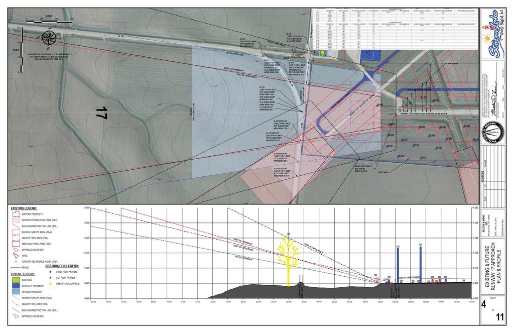
4
5
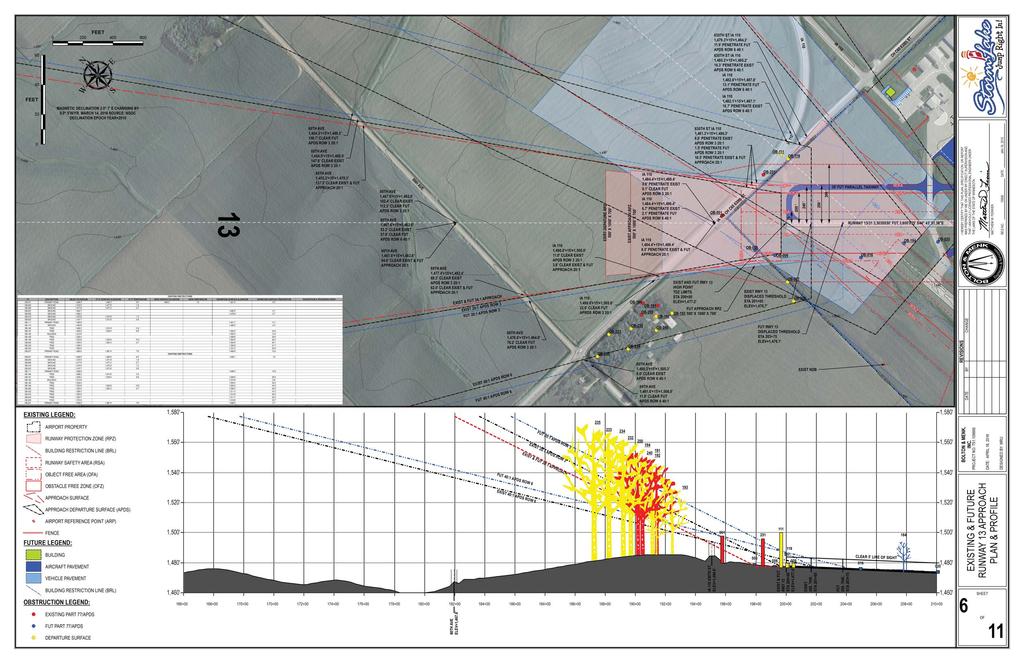
6
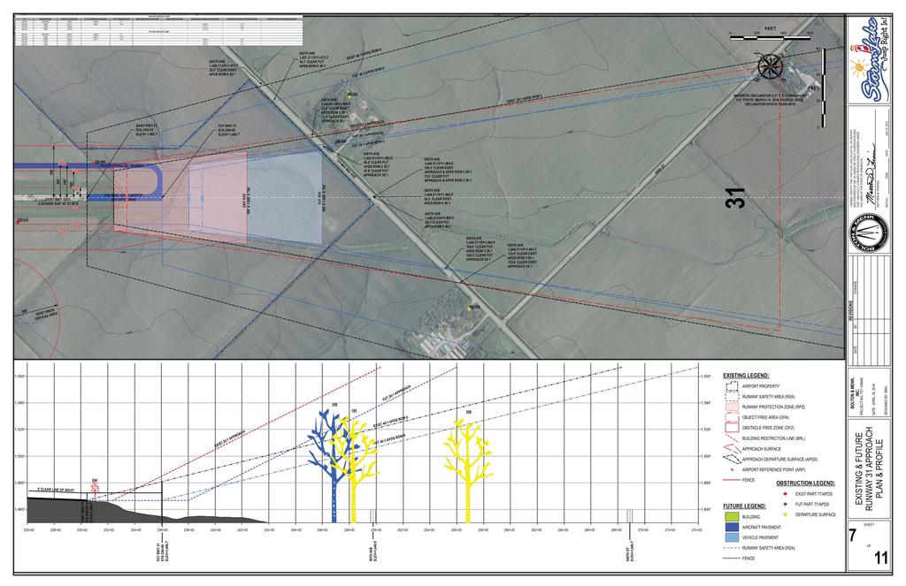
7
8
9 [ IA 0 IA 0 [ [ [ [ [ [ [ [ [ [ [ 40' TAXIWAY EXIST RUNWAY 13/ 3,0X50' S44 43' 51.38"E FUT ' PARALLEL TAXIWAY RA RA RA RA IA 0 CH C5 30th ST. WIND CONE 75 ' [ [ [ [ [ [ [ [ [ [ [ [ [ [ [ [ [ [ [ [ [ [ [ [ 200 ' AIRPORT ACCESS ROAD FUT ' PARALLEL TAXIWAY 0 ' 250 ' EXIST RUNWAY / 1,92X95' N 42' 5.49"E [ [ [ [ [ [ [ [ [ [ [ [ [ [ [ [ [ [ [ [ [ [ [ [ [ [ [ [ [ [ [ [ [ [ [ [ [ [ [ [ [ [ [ [ [ [ [ [ [ «34 «4 «5 «9 FUT AND EXIST VEHICLE PARKING CHAIN LINK FENCE 4' HIGH FUT TIE-DOWN AREA RZ RA RA RA RZ RZ 1,470' RA RZ GATE 390 ' «1 «2 «3 CHAIN LINK FENCE ' HIGH SLIDING GATE AIRPORT BEACON ELEV=1,475.' FUEL FACILITY (100LL & JET A) EXIST TIE-DOWN AREA 1,470' 25 ' 125 ' ««7 «8 0 ' 5 ' FUT APPRON «20 «21 25 ' 79 ' «22 «23 25 ' RZ RA RZ RA RZ RA CH C5 30th ST. RZ RA 84 ' ««12 «13 70 ' ««25 «2 «27 ' «14 «15 «1 «28 «29 «30 1 ' 5 ' ' ««18 «19 ««32 «33 10 ' [ [ [ [ [ [ [ [ [ [ [ [ [ [ [ [ [ [ [ [ [ [ [ [ [ [ [ [ [ [ [ [ [ [ [ [ [ [ [ [ [ [ [ [ [ [ [ [ [ [ [ [ [ [ [ [ [ [ [ [ [ [ [ 1,40' LEGEND: AIRPORT RUNWAY PROTECTION ZONE (RPZ) RUNWAY SAFETY AREA () OBSTACLE FREE ZONE (Z) OBJECT FREE AREA (A) BUILDING RESTRICTION LINE (BRL) +U AIRPORT REFERENCE POINT (ARP) [ [ [ FENCE LEGEND: BUILDING [ [ [ FENCE VEHICLE PAVEMENT AIRCRAFT PAVEMENT BUILDING RESTRICTION LINE (BRL) TIE-DOWN BUILDING TABLE ID EST. TOP ELEV. DESCRIPTION DISPOSITION ' TERMINAL FICE TO REMAIN ' FBO FICE TO REMAIN 3 1,505' MAINTENANCE EQUIPMENT STORAGE TO REMAIN 4 1,493' 4-UNIT CAROUSEL HANGAR TO REMAIN 5 1,493' 4-UNIT CAROUSEL HANGAR TO REMAIN 1,494' -UNIT TEE HANGAR TO REMAIN 7 1,49' -UNIT NESTED TEE HANGAR TO REMAIN 8 1,497' -UNIT NESTED TEE HANGAR TO REMAIN 9 1,503' PRIVATE SINGLE UNIT HANGAR TO REMAIN 10 BUILDING TABLE ID EST. TOP ELEV. DESCRIPTION DISPOSITION 45' X 45' HANGAR TO BE CONSTRUCTED 12 45' X 45' HANGAR TO BE CONSTRUCTED 13 45' X 45' HANGAR TO BE CONSTRUCTED 14 0' X 0' HANGAR TO BE CONSTRUCTED 15 0' X 0' HANGAR TO BE CONSTRUCTED 1 0' X 0' HANGAR TO BE CONSTRUCTED 0' X 0' HANGAR TO BE CONSTRUCTED 18 0' X 0' HANGAR TO BE CONSTRUCTED 19 0' X 0' HANGAR TO BE CONSTRUCTED 20 80' X 80' HANGAR TO BE CONSTRUCTED 21 80' X 80' HANGAR TO BE CONSTRUCTED 22 50' X 50' HANGAR TO BE CONSTRUCTED 23 7' X 1' HANGAR TO BE CONSTRUCTED 45' X 45' HANGAR TO BE CONSTRUCTED 25 45' X 45' HANGAR TO BE CONSTRUCTED 2 45' X 45' HANGAR TO BE CONSTRUCTED 27 45' X 45' HANGAR TO BE CONSTRUCTED 28 0' X 0' HANGAR TO BE CONSTRUCTED 29 0' X 0' HANGAR TO BE CONSTRUCTED 30 0' X 0' HANGAR TO BE CONSTRUCTED 0' X 0' HANGAR TO BE CONSTRUCTED 32 0' X 0' HANGAR TO BE CONSTRUCTED 33 0' X 0' HANGAR TO BE CONSTRUCTED 34 50' X 50' BUILDING TO BE CONSTRUCTED μ FEET MAGNETIC DECLINATION 2.0 7' E CHANGING BY 0.0 5'W/YR. MARCH 14, 201 SOURCE: NGDC DECLINATION EPOCH YEAR=2010 PROJECT NO: T DATE: APRIL 18, 201 & BUILDING AREA PLAN DATE: JAN 18, 201
10 THE CHURCH JESUS CHRIST LATTER-DAY SAINTS _ CHURCH MO SYNOD GENEALOGICAL STORM LAKE METHODIST MANOR SOCIETY LIBRARY STORM LAKE CITY LIBRARY RETIREMENT BV COUNTY COMMUNITY SCHOOLS COMMUNITY STORM LAKE BUENA VISTA UNIVERSITY ST JOHN LUTHERAN CHURCH HARKER HOUSE PRESBYTERY PROSPECT HILL ST MARY'S ST MARY'S GRADE & MIDDLE SCHOOL HEAD START COMMUNITY SCHOOLS STATE IOWA PUBLIC SAFETY COMMUNICATIONS 2003 CODE ORDINANCES, BUENA VISTA COUNTY, IOWA 3rd ST. RUSSELL ST. MEADOW LN. PIERCE DR. ONIEDA ST. GENESEO ST. MAE ST. RUSSELL ST. IOWA ST. SHOREWAY RD. 4th ST. GRAND AVE. OTSEGO ST. HUDSON ST. HIGHWAY ST. 1st ST. SENECA ST. SUPERIOR ST. 1st ST. 4th ST. BAIR ST. COLLEGE AVE. IRVING ST. LAKE AVE. MICHIGAN ST. MALLARD AVE. PHEASANT AVE. SHORE DR. SOUTH RD. SOUTH COVE STONEY POINT RD. CH C5 30th ST. 40th ST. 0th AVE. 100th AVE. 0th ST. CASINO RD. 5th ST. CLOVER LN. PRAIRIE LN. LEONA DR. KELVIN RD. PROJECT NO: T DATE: APRIL 18, 201 DATE: JAN 18, 201 LAND USE LEGEND: PRIME AG A-1 LIMITED AG A-2 MOBILE HOME MH INDUSTRIAL I-1 RESIDENTIAL SINGLE FAMILY R-1 RESIDENTIAL MULTIFAMILY R-2 SE LEGEND: Airport Tall Structure Zoning.4 SECTION 4. Use Restrictions. Notwithstanding any other provisions of Section 4, no use may be made of land or water within the City of Storm Lake, Buena Vista County, or Sac County in such a manner as to interfere with the operation of any airborne aircraft. The following special requirements shall apply to each permitted use. A. All lights or illumination used in conjunction with street, parking signs or use of land and structures shall be arranged and operated in such a manner that is not misleading or dangerous to aircraft operating from the Storm Lake Municipal Airport or in the vicinity thereof. B. No operations from any use shall produce smoke, glare, or other visual hazards within three (3) statute miles of any usable runway of the Storm Lake Municipal Airport. C. No operations from any use in the City of Storm Lake, Buena Vista County or Sac County, shall produce electronic interference with navigation signals or radio communication between airport and aircraft INSTITUTIONS AIRPORT CITY STORM LAKE RUNWAY PROTECTION ZONE (RPZ) RUNWAY PROTECTION ZONE (RPZ) PRIMARY SURFACE B-RUNWAY APPROACH SURFACE C-TRANSITIONAL SURFACE D-HORIZONTAL SURFACE E-CONICAL SURFACE PRIMARY SURFACE B-RUNWAY APPROACH SURFACE C-TRANSITIONAL SURFACE D-HORIZONTAL SURFACE E-CONICAL SURFACE LAND USE & ZONING μ FEET 0 1,500 3,000 4,500 MAGNETIC DECLINATION 2.0 7' E CHANGING BY 0.0 5'W/YR. MARCH 14, 201 SOURCE: NGDC DECLINATION EPOCH YEAR= LAKE SHORE DR. DR. PARK CHAUTAUQUA BAY VIEW ST. DR. VISTA SCOTT ST. EMERALD DR. IA 0 W MARINA RD. 0 IA RUNWAY / 1,92X95' N 42' 5.49"E RUNWAY 13/ 3,30X50' S44 43' 51.38"E RUNWAY / 5,002'X75' S3 54'.48"E CH M43 90th AVE. 50th ST. WHITE CAP RD. 80th AVE. 20th ST. IA 0 CH C5 30th ST. CH C3 10th ST. 70th AVE. 40th ST. 0th ST. 0th AVE. IA 0 0th AVE. IA 0 0th AVE. CH C5 30th ST.
11 EXHIBIT "A" AIRPORT INVENTORY MAP PROJECT NO: T DATE: APRIL 18, 201 DATE: JAN 18, 201 RA 1 2 RUNWAY / 1,92X95' N 42' 5.49"E RUNWAY 13/ 3,30X50' S44 43' 51.38"E 3 RUNWAY / 5,002'X75' S3 54'.48"E E-1 E E-5 E-4 E-3 TABLE PARCEL TYPE INTEREST ACREAGE GRANTOR AIP/STATE PROJECT # ACQUISITION DATE CONVEYANCE INSTRUMENT NOTES 1 FEE FEE 4.28 /20/ FEE S FEE S FEE S 197 FEE FEE E-1 CLEAR ZONE EASEMENT E-2 CLEAR ZONE EASEMENT E-3 CLEAR ZONE EASEMENT E-4 CLEAR ZONE EASEMENT E-5 CLEAR ZONE EASEMENT TOTAL FEE: 9.28 TOTAL EASEMENT: TOTAL: LEGEND: LEGEND: AIRPORT 1 7 PARCELS 2 E-1 RUNWAY PROTECTION ZONE (RPZ) 3 E-2 BUILDING RESTRICTION LINE (BRL) 4 E-3 RUNWAY PROTECTION ZONE (RPZ) 5 E-4 BUILDING RESTRICTION LINE (BRL) E-5 μ FEET ,200 1,800 MAGNETIC DECLINATION 2.0 7' E CHANGING BY 0.0 5'W/YR. MARCH 14, 201 SOURCE: NGDC DECLINATION EPOCH YEAR=2010 STONEY POINT RD. CH C5 30th ST. 40th ST. CH M43 90th AVE. RA RA IA 0 0 IA RA RA RA RA RA RA RA RA 50th ST. RA RA 80th AVE. IA 0 CH C5 30th ST.
TECHNICAL REPORT #7 Palm Beach International Airport Airport Layout Plan
 TECHNICAL REPORT #7 Palm Beach International Airport Airport Layout Plan Technical Report #7 Palm Beach International Airport Layout Plan Palm Beach International Airport Prepared for Palm Beach County
DATE OF AERIAL PHOTOGRAPHY:
 DESCRIPTION RUNWAY SAFETY AREA RUNWAY PROTECTION ZONE TAXIWAY OBJECT FREE AREA DATE OF AERIAL PHOTOGRAPHY: 6-17-01 RUNWAY SAFETY AREA FOR PORTION OF RUNWAY 16L-34R SOUTH OF RUNWAY BRIDGE HAS A FAA WAIVER
DRAFT MASTER PLAN UPDATE
 DRAFT MASTER PLAN UPDATE CHAPTER VI: AIRPORT LAYOUT PLAN NARRATIVE DRAFT REPORT APRIL 2017 PREPARED BY: Table of Contents WESTCHESTER COUNTY AIRPORT 6 AIRPORT LAYOUT PLAN NARRATIVE REPORT... 6-1 6.1 AGIS
Chapter Six ALP Drawings. Tacoma Narrows Airport. Master Plan Update
 Chapter Six ALP Drawings Master Plan Update The master planning process for the (Airport) has evolved through efforts in the previous chapters to analyze future aviation demand, establish airside and landside
Chapter 4 Airport Facility Requirements
 Chapter 4 Airport Facility Requirements Introduction CHAPTER 4 AIRPORT FACILITY REQUIREMENTS MAY 2013-1 Organization of Materials CHAPTER 4 AIRPORT FACILITY REQUIREMENTS MAY 2013-2 RPZ - ROAD RPZ - NON-AIRPORT
Source: Chippewa Valley Regional Airport ASOS, Period of Record
 Chapter 1 Inventory Runway wind coverage is the percentage of time a runway can be used without exceeding allowable crosswind velocities. Allowable crosswind velocities vary depending on aircraft size
AIRPORT LAYOUT PLAN FOR FRIEDMAN MEMORIAL REPLACEMENT AIRPORT - SITE 12 FRIEDMAN MEMORIAL AIRPORT AUTHORITY INDEX OF SHEETS SHEET TITLE
 GOODING MUNICIPAL SOURCE: JeppView 3.6.3.1 (Printed May 19, 2010) MAGIC VALLEY REGIONAL BURLEY MUNICIPAL LOCATION MAP NTS - SITE 12 AIRPORT LAYOUT PLAN FOR FRIEDMAN MEMORIAL REPLACEMENT AIRPORT - SITE
Chapter 9 - AIRPORT SYSTEM DESIGN
 Chapter 9 - AIRPORT SYSTEM DESIGN 9.01 GENERAL This chapter discusses the development program for Dutchess County Airport to the year 2020. This airport system design is based upon the airport's existing
Acronyms. Airport Layout Plan Report Appendix A A-1
 Appendix A Acronyms AC... Advisory Circular ADG... Airplane Design Group ADO... Airport District Office AGL... Above Ground Level AIM... Aeronautical Information Manual AIP... Airport Improvement Program
Chippewa-Eau Claire Metropolitan Planning Area Long Range Transportation Plan
 1.2.7 2010 Eau Claire County Comprehensive Plan According to Eau Claire County s most recent comprehensive plan, the County will limit land use development adjacent to EAU in order to preserve the ability
FACILITY REQUIREMENTS SUMMARY OF KEY ISSUES OVERVIEW
 FACILITY REQUIREMENTS SUMMARY OF KEY ISSUES OVERVIEW This summary is intended to provide a brief overview of the key issues associated with conformance to FAA standards at Methow Valley State Airport.
FINAL SUMMARY REPORT
 FINAL SUMMARY REPORT RUNWAY 1-19 EXTENSION ANALYSIS at MIDDLEBURY STATE AIRPORT PREPARED BY ROXBURY, VERMONT APRIL 2008 FINAL SUMMARY REPORT TABLE OF CONTENTS SECTION PAGE 1.1 INTRODUCTION...1 2.1 OBSTRUCTION
Chapter One INVENTORY
 Chapter One INVENTORY Airport Layout Plan Report The initial step in the preparation of the Airport Layout Plan Report for is the collection of information pertaining to the Airport and the area it serves.
Chapter 4 Airport Capacity Assessment and Identification of Facility Needs
 Chapter 4 Airport Capacity Assessment and Identification of Facility Needs 4.1 Introduction The purpose of the airport capacity assessment and identification of facility needs is to evaluate the single
The following criteria shall be applied within the boundaries of the AO District:
 Sec. 419 (a) Purpose AIRPORT OVERLAY DISTRICT (AO) The purpose of the Airport Overlay District is to regulate and restrict the height of structures, objects, or natural growth, regulate the locations of
FACILITY REQUIREMENTS 5.1 Introduction
 Chapter 5 FACILITY REQUIREMENTS 5.1 Introduction The facility requirements section of this study defines the physical facilities needed to safely and efficiently accommodate the current and future aviation
Chapter 4 Airport Facility Requirements. Introduction
 Chapter 4 Airport Facility Requirements Introduction The airport facility requirements analysis combines the results of the inventory and forecasts contained in Chapters Two and Three, and the applicable
Appendix C AIRPORT LAYOUT PLANS
 Appendix C AIRPORT LAYOUT PLANS Appendix C AIRPORT LAYOUT PLANS Airport Master Plan Santa Barbara Airport As part of this Airport Master Plan, the Federal Aviation Administration (FAA) requires the development
GLOSSARY A.1 ABBREVIATIONS/ACRONYMS
 Appendices Glossary A A GLOSSARY A.1 ABBREVIATIONS/ACRONYMS AC ADF ADPM AGL AIP ALP ALS ALSF-1 ARC ARFF ARP ARTCC ASDA ASO ASR ASV ATC ATCT AVGAS BLI CBP CIP - Advisory Circular - Automatic Direction
4.0 FACILITY REQUIREMENTS
 4.0 FACILITY REQUIREMENTS The purpose of this chapter of Master Plan is to identify the needs for additional facilities, or improvements to existing facilities over the planning period. By comparing current
OVERVIEW BASIC DESIGN FACTORS. Demand Determinants
 3 Airfield Airfield Design Design OVERVIEW The basic configuration of the runway and taxiway system at Hanford Municipal Airport has changed moderately since the airport was constructed in 1950. These
6.1 INTRODUCTION 6.2 AIRSIDE ALTERNATIVES NORTH PERRY AIRPORT MASTER PLAN UPDATE RUNWAY LENGTH REQUIREMENTS SECTION 6: ALTERNATIVES ANALYSIS
 6.1 INTRODUCTION In the previous chapter, facility needs for the 20-year planning horizon were identified. The next step in the planning process is to identify and evaluate the various ways certain facilities
Preliminary Findings of Proposed Alternative
 Preliminary Findings of Proposed Alternative The attached drawing provides a schematic layout of the proposed alternative that will be discussed on July 27, 2010. A full report will follow and should be
SITE ELEVATION AMSL...Ground Elevation in feet AMSL STRUCTURE HEIGHT...Height Above Ground Level OVERALL HEIGHT AMSL...Total Overall Height AMSL
 ******************************************** * Federal Airways & Airspace * * Summary Report * ******************************************** File: User Assigned File Name Latitude: NAD83 Coordinate Longitude:
Boise Municipal Code. Chapter DEFINITIONS
 Chapter 12-03 DEFINITIONS Sections: 12-03-01 ADMINISTRATOR 12-03-02 AIRPORT DESIGNATIONS 12-03-03 AIRPORT HAZARD 12-03-04 AIRPORT HEIGHT LIMITATIONS 12-03-05 AIRPORT REFERENCE POINT 12-03-06 AIRPORT INSTRUMENT
Flying Cloud Airport (FCM) Zoning Process: Informing a Mn/DOT Path Forward
 Zoning Process: Informing a Mn/DOT Path Forward") : Informing a Mn/DOT Path Forward A Review of the Flying Cloud Airport (FCM) Joint Airport Zoning Board (JAZB) Process and the Draft Airport Zoning Ordinance B A RPZ RPZ A B C Zone Chad E. Leqve Director
: Informing a Mn/DOT Path Forward A Review of the Flying Cloud Airport (FCM) Joint Airport Zoning Board (JAZB) Process and the Draft Airport Zoning Ordinance B A RPZ RPZ A B C Zone Chad E. Leqve Director
ADVISORY CIRCULAR ON CALCULATION OF DECLARED DISTANCES
 Page 1 of 6 1. PURPOSE This Advisory circular (AC) provides guidance to operators to calculated declared distances at aerodrome for safe use of runway and promulgation of aeronautical data to the aeronautical
Appendix A - Glossary
 Appendix A - Glossary The terms and definitions here are relevant to airport design standards and retrieved from AC 150/5300-13A, Airport Design. A Accelerate-Stop Distance Available (ASDA). See Declared
PLU Airport Master Plan. Master Plan Advisory Committee (MPAC) Meeting #4 March 19, 2018
 Meeting #4 March 19, 2018") PLU Airport Master Plan Master Plan Advisory Committee (MPAC) Meeting #4 March 19, 2018 Meeting Agenda 1. Master Plan Status [5 Minutes] 2. Preferred Forecasts [15 Minutes] 3. Runway Length Options [45
PLU Airport Master Plan Master Plan Advisory Committee (MPAC) Meeting #4 March 19, 2018 Meeting Agenda 1. Master Plan Status [5 Minutes] 2. Preferred Forecasts [15 Minutes] 3. Runway Length Options [45
Airfield Design. Public Review Draft OVERVIEW BASIC DESIGN FACTORS. Airport Role
 Public Review Draft 3 Airfield Design OVERVIEW The Facilities Plan, Figure 3D, presents the recommended airfield improvements. The principal airfield design issues examined in this chapter are the optimal
1.1.3 Taxiways. Figure 1-15: Taxiway Data. DRAFT Inventory TYPICAL PAVEMENT CROSS-SECTION LIGHTING TYPE LENGTH (FEET) WIDTH (FEET) LIGHTING CONDITION
 WIDTH (FEET) LIGHTING CONDITION") 1.1.3 Taxiways EWN has an extensive network of taxiways and taxilanes connecting the terminal, air cargo, and general aviation areas with the runways as listed in Figure 1-15. A 50-foot wide parallel taxiway
1.1.3 Taxiways EWN has an extensive network of taxiways and taxilanes connecting the terminal, air cargo, and general aviation areas with the runways as listed in Figure 1-15. A 50-foot wide parallel taxiway
SECTION 4: AIRPORT FACILITY NEEDS
 SECTION 4: AIRPORT FACILITY NEEDS 4.1 AIRPORT GEOMETRIC DESIGN FACTORS This section identifies airfield and terminal area facilities to satisfy the 20-year forecast of aviation demand at the Dare County
MASTER PLAN CONCEPT 1 DRAFT
 The Airport Master Plan Update for Dallas Executive Airport has included the development of aviation demand forecasts, an assessment of future facility needs, and the evaluation of airport development
Airport Layout Plan Narrative Report
 Airport Layout Plan Narrative Report Yuba County Airport Olivehurst, California Prepared for County of Yuba Prepared by Mead & Hunt, Inc. March 23, 2017 YUBA COUNTY AIRPORT AIRPORT LAYOUT PLAN NARRATIVE
Chapter 4 Airport Facility Requirements
 Chapter 4 Airport Facility Requirements The evaluation of airport facility requirements uses the results of the inventory and forecasts contained in Chapters Two and Three, as well as established planning
AIRPORT FACILITY REQUIREMENTS
 4 AIRPORT FACILITY REQUIREMENTS AIRPORT DESIGN FACTORS This chapter identifies the long-range airfield and terminal area facilities needed to satisfy the 20-year forecast of aviation demand at the Bowers
BELLINGHAM INTERNATIONAL AIRPORT. Appendix A. Glossary. Prepared by: Leibowitz & Horton AMC JUB Engineers, Inc.
 BELLINGHAM INTERNATIONAL AIRPORT MASTER PLAN UPDATE Appendix A Glossary Prepared by: Leibowitz & Horton AMC JUB Engineers, Inc. A APPENDIX A: GLOSSARY A.1 ABBREVIATIONS AC - Advisory Circular ADF - Automatic
ORDINANCE NO. _2013-
 ORDINANCE NO. _2013- AN ORDINANCE OF THE TOWNSHIP OF CONEWAGO, DAUPHIN COUNTY, PENNSYLVANIA, PROVIDING FOR AIRPORT ZONING REGULATIONS WITHIN THE AIRPORT ZONING OVERLAY DISTRICT CREATED BY THIS ORDINANCE
JANUARY 2013 Friedman Memorial Airport Pomeroy, Chris
 JANUARY 2013 Friedman Memorial Airport Pomeroy, Chris Friedman Memorial Airport / T-O Engineers Airport Alternatives Technical Analysis Table of Contents 1.0 Background and Purpose of Analysis... 1 1.1
chapter 5 Recommended Master Plan Concept airport master plan MASTER PLAN CONCEPT
 chapter 5 Recommended Master Plan Concept airport master plan The planning process for Coolidge Municipal Airport has included several analytical efforts in the previous chapters intended to project potential
Chapter 5 Airport Facility Requirements
 Chapter 5 Airport Facility Requirements Introduction The evaluation of airport facility requirements uses the results of the inventory and forecasts contained in Chapters Two and Three, as well as established
Chapter Three AIRPORT FACILITY REQUIREMENTS/ALTERNATIVES
 Chapter Three AIRPORT FACILITY REQUIREMENTS/ALTERNATIVES Airport Layout Plan Report In this chapter, existing components of the Airport are evaluated so that the capacities of the overall system are identified.
Lopez Island Airport Master Plan Update. Public Meeting June 15, 2017
 Lopez Island Airport Master Plan Update Public Meeting June 15, 2017 Master Plan Update Team Reid Middleton/Everett, WA Shannon Kinsella, Project Manager Melania Haagsma, Project Engineer Mead & Hunt/Tulsa,
C > Capacity Analysis and Facility Requirements
 Buchanan Field Buchanan Field Airport Master Planning Program C. CAPACITY ANALYSIS & FACILITY REQUIREMENTS C > Capacity Analysis and Facility Requirements INTRODUCTION. The capacity of an airfield is primarily
BELFAST MUNICIPAL AIRPORT OVERVIEW
 BELFAST MUNICIPAL AIRPORT OVERVIEW LOCATION AND HISTORY Belfast Municipal Airport (Federal Aviation Administration (FAA) airport code BST, International Civil Aviation Organization airport code KBST, FAA
Chapter 5 Facility Requirements
 Chapter 5 Facility Requirements Chapter 5 Facility Requirements INTRODUCTION Chapter 4 produced a forecast of traffic volumes estimated to be generated at the airport during the 20- year forecast period.
Grants Pass Airport Master Plan & Airport Layout Plan Update
 Attendees: Grants Pass Airport Master Plan & Airport Layout Plan Update Meeting #3 January 26, 2010 Merlin Community Center 100 Acorn Street, Merlin 5:45 7:15 p.m. Josephine County Department of Airports:
Merritt Island Airport
 TABLE OF CONTENTS CHAPTER 1 INTRODUCTION... 1-1 INTRODUCTION AND PROJECT OVERVIEW... 1-1 General Guidelines... 1-1 Prior Planning Documentation... 1-2 Key Issues... 1-2 Goals and Objectives... 1-2 Regulatory
CHAPTER D Capacity Analysis and Facility Requirements INTRODUCTION
 CHAPTER D Capacity Analysis and Facility Requirements INTRODUCTION The capacity of an airfield is primarily a function of the major aircraft operating surfaces that compose the facility and the configuration
5.0 ALTERNATIVES ANALYSIS
 5.0 ALTERNATIVES ANALYSIS The Alternative Analysis chapter describes and evaluates the various development alternatives considered for. In addition, it presents a preferred development plan that accommodates
8.0 AIRPORT LAYOUT PLANS
 8.0 AIRPORT LAYOUT PLANS This chapter presents a detailed graphic and narrative description of the selected development concept for General Mitchell International Airport (MKE). The plans package presented
Technical Advisory Committee Meeting February 29, 2016
 Technical Advisory Committee Meeting February 29, 2016 Meeting Agenda Introduction Recap of Planning Process Project Status Goals and Objectives Forecasts of Aviation Demand Overview of Facility Requirements
Chapter 5 Airport Development Alternatives
 Chapter 5 Airport Development Alternatives Introduction CHAPTER 5 AIRPORT DEVELOPMENT ALTERNATIVES JUNE 2013-1 Evaluation Process No-Action Alternative CHAPTER 5 AIRPORT DEVELOPMENT ALTERNATIVES JUNE 2013-2
SUMMARY OF QUANTITES NO. ITEM DESCRIPTION UNIT QUANTITY DRAWING NUMBER TITLE GENERAL ELECTRICAL
 SRQ-D-FOTS-G000 DRAWING NUMBER TITLE GENERAL 1 SRQ-D-FOTS-G000 COVER SHEET 2 SRQ-D-FOTS-G001 DRAWING INDEX AND SUMMARY OF QUANTITIES 3 SRQ-D-FOTS-G002 LEGEND AND ABBREVIATIONS 4 SRQ-D-FOTS-G101 OVERALL
FAA Update. Dakota-Minnesota (DMA) Airports District Office. Federal Aviation Administration. Presented to: By: Date: South Dakota Airports Conference
 Airports District Office. Federal Aviation Administration. Presented to: By: Date: South Dakota Airports Conference") FAA Update Dakota-Minnesota (DMA) Airports District Office Presented to: By: Date: South Dakota Airports Conference Chris Hugunin & Dave Anderson March 18, 2015 FY 2014 DMA ADO Total AIP Funding $107.2
FAA Update Dakota-Minnesota (DMA) Airports District Office Presented to: By: Date: South Dakota Airports Conference Chris Hugunin & Dave Anderson March 18, 2015 FY 2014 DMA ADO Total AIP Funding $107.2
Airport Obstruction Standards
 Airport Obstruction Standards Dr. Antonio Trani Department of Civil and Environmental Engineering Virginia Tech Outline of this Presentation Obstructions to navigation around airports Discussion of Federal
CHAPTER 3 AIRPORT FACILITY REQUIREMENTS
 CHAPTER 3 AIRPORT FACILITY REQUIREMENTS 3.1 Introduction The existing runway and taxiway system at Skyhaven Airport provides more than adequate operational capacity to accommodate future peak hour and
Chapter 5. Facility Requirements
 Chapter 5 Facility Requirements Chapter 5 Facility Requirements INTRODUCTION The Baseline Forecast was used to determine facility requirements. Chapter 4 produced a forecast of traffic volumes expected
Tallahassee International Airport Master Plan. Technical Advisory Committee Meeting #2 October 19, 2016
 Tallahassee International Airport Master Plan Technical Advisory Committee Meeting #2 October 19, 2016 Agenda Welcome / Introductions Master Plan Process and Project Status Forecast of Aviation Demand
Airport Master Plan. Hutchinson Municipal Airport Butler Field (HCD) Hutchinson, Minnesota. July 2015
 Hutchinson, Minnesota. July 2015") Airport Master Plan Hutchinson Municipal Airport Butler Field HCD) Hutchinson, Minnesota July 2015 Submitted by: Bolton & Menk, Inc. 12224 Nicollet Avenue Burnsville, MN 55337 P: 952-890-0509 Airport Sponsor:
Airport Master Plan Hutchinson Municipal Airport Butler Field HCD) Hutchinson, Minnesota July 2015 Submitted by: Bolton & Menk, Inc. 12224 Nicollet Avenue Burnsville, MN 55337 P: 952-890-0509 Airport Sponsor:
ABOVE GROUND LEVEL. The elevation of a point or surface above the ground. ACCELERATE STOP DISTANCE AVAILABLE (ASDA). See declared distances
. See declared distances") Appendix A Glossary of Terms Master Plan Update DEFINITIONS ABOVE GROUND LEVEL. The elevation of a point or surface above the ground. ACCELERATE STOP DISTANCE AVAILABLE (ASDA). See declared distances ADVISORY
Appendix A Glossary of Terms Master Plan Update DEFINITIONS ABOVE GROUND LEVEL. The elevation of a point or surface above the ground. ACCELERATE STOP DISTANCE AVAILABLE (ASDA). See declared distances ADVISORY
3 INTRODUCTION. Chapter Three Facility Requirements. Facility Requirements PEAKING CHARACTERISTICS
 Chapter Three Facility Requirements 3 INTRODUCTION This chapter identifies the long-range airfield and terminal area facilities needed to satisfy the 20-year forecast of aviation demand at Monett Municipal
Agenda: SASP SAC Meeting 3
 Agenda: SASP SAC Meeting 3 Date: 04/12/18 Public Involvement Plan Update Defining the System Recommended Classifications Discussion Break Review current system Outreach what we heard Proposed changes Classification
Table of Contents. Overview Objectives Key Issues Process...1-3
 Table of Contents Chapter One Introduction Overview...1-1 Objectives...1-1 Key Issues...1-2 Process...1-3 Chapter Two Inventory of Existing Conditions Airport Setting...2-1 Locale...2-1 Airport Surroundings...2-5
CHAUTAUQUA COUNTY/ DUNKIRK AIRPORT
 CHAUTAUQUA COUNTY/ DUNKIRK AIRPORT May 2017 Airport Master Plan Update FINAL Prepared For: Chautauqua County, New York Prepared By: Passero Associates FAA AIP # 3-36-0022-048-2014 NYDOT # 5905.78 Chautauqua
Appendix A GLOSSARY OF TERMS AND ACRONYMS
 Appendix A GLOSSARY OF TERMS AND ACRONYMS Airport Layout Plan Update Illinois Valley Airport DEFINITIONS ACCELERATE STOP DISTANCE AVAILABLE (ASDA). See declared distances. AIR CARRIER. An operator, which:
DRAFT FINAL REPORT AIRPORT MASTER PLAN. Rifle Garfield County Airport Revised May 15, 2014
 DRAFT FINAL REPORT AIRPORT MASTER PLAN Rifle Garfield County Airport Revised May 15, 2014 As required by Paragraph 425.B(4) of FAA Order 5100.38C, Airport Improvement Program (AIP) Handbook: The preparation
Airport Master Plan. Brookings Regional Airport. Runway Runway 17-35
 Runway 17-35 Airport Master Plan Runway 12-30 Brookings Regional Airport Table of Contents Table of Contents Chapter 1: Master Plan Goals... 1-1 1.1. Introduction... 1 1.2. Objective 1 Identify improvements
CHAPTER 3 FACILITY REQUIREMENTS
 CHAPTER 3 FACILITY REQUIREMENTS 3.1 INTRODUCTION To properly plan for the future requirements of Newport News/Williamsburg International Airport, it is necessary to translate the forecasts of aviation
4.0 FACILITY REQUIREMENTS
 4.0 FACILITY REQUIREMENTS This chapter documents the facilities needed to meet the demand requirements as described in Chapter 3, Aviation Activity Forecasts. Current facilities were examined to determine
Chapter 2: Existing Facilities
 Chapter 2: Existing Facilities This chapter describes the existing conditions at the airport and provides an inventory of existing facilities and infrastructure. It provides the baseline for future requirements,
General Aviation Master Plan Update
 Peter O. Knight Airport Public Meeting #2 Peter O. Knight Airport Agenda Welcome and Introductions HCAA System of Airports Purpose of Public Meetings Master Plan Status Update Next Steps Q & A 2 Our System
-NOTE: NOT TO BE USED FOR NAVIGATION PURPOSES-
 APPENDIX 1-B INSTRUMENT APPROACH PROCEDURES March 2010 SKYHAVEN AIRPORT -NOTE: NOT TO BE USED FOR NAVIGATION PURPOSES- -NOTE: NOT TO BE USED FOR NAVIGATION PURPOSES- -NOTE: NOT TO BE USED FOR NAVIGATION
Actual Runway Length: The length of full-width, usable runway from end to end or full strength pavement where those runways are paved
 Actual Runway Length: The length of full-width, usable runway from end to end or full strength pavement where those runways are paved ADF: Automatic Direction Finder Advisory Circular (AC): A series of
Chapter 3 FACILITY REQUIREMENTS
 Chapter 3 FACILITY REQUIREMENTS Chapter Three Facility Requirements To properly plan for the future of Ryan Airfield, it is necessary to translate forecast aviation demand into the specific types and quantities
Chapter 4 Facility Requirements
 Chapter 4 Facility Requirements Introduction This chapter evaluates the existing airport facilities and identifies improvements needed to effectively meet the forecasted demand levels discussed in the
Hartford-Brainard Airport Potential Runway Closure White Paper
 Hartford-Brainard Airport Potential Runway 11-29 Closure White Paper June 2012 In recent years there has been discussion regarding the necessity of Runway 11-29 to the Hartford- Brainard Airport (HFD)
Chapter 8 Airport Layout Plan
 Chapter 8 Airport Layout Plan Chapter 8 Airport Layout Drawings Introduction The options that were considered for the long-term development of Ken Jernstedt Airfield resulted in the selection of a preferred
AD 2. AERODROMES VAKS AD 2.2 AERODROME GEOGRAPHICAL AND ADMINISTRATIVE DATA
 AD 2-1 AD 2. AERODROMES AD 2.1 AERODROME LOCATION INDICATOR AND NAME - KESHOD / DOMESTIC AD 2.2 AERODROME GEOGRAPHICAL AND ADMINISTRATIVE DATA 1 Aerodrome reference point coordinates and its site 2 Direction
EGSL ANDREWSFIELD EGSL AD 2.1 AERODROME LOCATION INDICATOR AND NAME EGSL AD 2.2 AERODROME GEOGRAPHICAL AND ADMINISTRATIVE DATA
 UNITED KINGDOM AIP AD 2.EGSL-1 26 May 2016 EGSL ANDREWSFIELD EGSL AD 2.1 AERODROME LOCATION INDICATOR AND NAME EGSL ANDREWSFIELD EGSL AD 2.2 AERODROME GEOGRAPHICAL AND ADMINISTRATIVE DATA 1 ARP coordinates
4.0 AIRFIELD CAPACITY & FACILITY REQUIREMENTS
 4.0 AIRFIELD CAPACITY & FACILITY REQUIREMENTS A key step in the Airport Master Plan (AMP) process is determining future requirements for airport facilities that will allow for airside and landside development
Thursday, May 2 nd, 2013 South St. Paul Municipal Airport Meeting Room 4:00 p.m. 5:30 p.m. MEETING NOTES
 SOUTH ST. PAUL MUNICIPAL AIRPORT FLEMING FIELD MASTER PLAN ADVISORY GROUP MEETING #2 Thursday, May 2 nd, 2013 South St. Paul Municipal Airport Meeting Room 4:00 p.m. 5:30 p.m. MEETING NOTES The purpose
From concept through completion, CGA is your AVIATION engineering firm!
 The State of Iowa has 120 general aviation airports. Our staff specializes in serving these airports with their engineering needs. Aviation lighting and navigational aids Environmental and financial feasibility
Aerodrome Obstacle Survey Information Checks
 United Kingdom Overseas Territories Aviation Circular OTAC 139-20 Aerodrome Obstacle Survey Information Checks Issue 2.00 26 May 2017 Effective on issue GENERAL Overseas Territories Aviation Circulars
LATVIAN AIP DATA SET
 LATVIAN AIP DATA SET Interregional EUR/MID PANS AIM Workshop (Paris, France, 10-12 July 2018) Dr. Vadim Tumarkin Head of AIS Latvijas Gaisa Satiksme vadims.tumarkins@lgs.lv GENERAL PROVISION FOR DIGITAL
CHAPTER 1 BACKGROUND AND PROPOSED ACTION
 CHAPTER 1 BACKGROUND AND PROPOSED ACTION 1.0 INTRODUCTION An Environmental Assessment (EA) evaluates the effects of a proposed Federal action on the surrounding environment and is prepared in compliance
Addendum - Airport Development Alternatives (Chapter 6)
") Bowers Field Addendum - Airport Development Alternatives (Chapter 6) This addendum to the Airport Development Alternatives chapter includes the preferred airside development alternative and the preliminary
Bowers Field Addendum - Airport Development Alternatives (Chapter 6) This addendum to the Airport Development Alternatives chapter includes the preferred airside development alternative and the preliminary
CHAPTER 1 INTRODUCTION AND BACKGROUND
 CHAPTER 1 INTRODUCTION AND BACKGROUND An Environmental Assessment (EA) evaluates the effects of a proposed Federal action on the surrounding environment and is prepared in compliance with the National
AERODROME DATA KESHOD AIRPORT, KESHOD (VAKS)
") TEL: 91-11-24632950 Extn: 2219/2233 AFS: VIDDYXAX FAX: 91-11-24615508 Email: gmais@aai.aero INDIA AERONAUTICAL INFORMATION SERVICE AIRPORTS AUTHORITY OF INDIA RAJIV GANDHI BHAVAN SAFDARJUNG AIRPORT NEW
TEL: 91-11-24632950 Extn: 2219/2233 AFS: VIDDYXAX FAX: 91-11-24615508 Email: gmais@aai.aero INDIA AERONAUTICAL INFORMATION SERVICE AIRPORTS AUTHORITY OF INDIA RAJIV GANDHI BHAVAN SAFDARJUNG AIRPORT NEW
Chapter 4.0 Facility Requirements
 Chapter 4.0 Facility Requirements Having inventoried the existing infrastructure and forecasted demand, determining airport facility requirements is the next essential step in the airport master planning
STUDY WORK GROUP MEETING No. 3. November 29, 2016
 STUDY WORK GROUP MEETING No. 3 November 29, 2016 Agenda Welcome and introductions Update project schedule Brief overview of previous SWG meeting Update on aviation forecasts Introduction to airfield demand/capacity
** DETERMINATION OF NO HAZARD TO AIR NAVIGATION **
 Mail Processing Center Federal Aviation Administration Southwest Regional Office Obstruction Evaluation Group 2601 Meacham Boulevard Fort Worth, TX 76137 Issued Date: 05/16/2011 Aeronautical Study No.
Facility Requirements
 4. This chapter presents the airside and landside facility requirements necessary to accommodate existing and forecasted demand at Erie International Airport (ERI or the Airport) in accordance with Federal
Facility Requirements
 C H A P T E R T H R E E Facility Requirements 3.0 OVERVIEW Airport planning for facility requirements is based upon addressing any existing issues and accommodating the probable demand that may occur over
AD 2. AERODROMES VOAT AD 2.2 AERODROME GEOGRAPHICAL AND ADMINISTRATIVE DATA
 AD 2-1 AD 2. AERODROMES AD 2.1 AERODROME LOCATION INDICATOR AND NAME - AGATTI / DOMESTIC AD 2.2 AERODROME GEOGRAPHICAL AND ADMINISTRATIVE DATA 1 Aerodrome reference point coordinates and its site 2 Direction
CHAPTER 3 ALTERNATIVES CONSIDERED
 CHAPTER 3 ALTERNATIVES CONSIDERED 3.0 ALTERNATIVES The 2010 Stevensville Airport Master Plan contained five (5) airside development options designed to meet projected demands. Each of the options from
Table of Contents. List of Tables. Cincinnati/Northern Kentucky International Airport 2035 Master Plan Update
 Table of Contents 7.1. Airport Layout Plan (Existing Conditions)... 2 7.2. Airport Layout Plan (Future Conditions)... 3 7.3. Technical Data Sheet... 5 7.4. Commercial Terminal Area Drawing... 5 7.5. East
Wiscasset Municipal Airport Master Plan Update October 2014 Section 2 Existing Conditions
 GENERAL The first step in the airport master planning process involves gathering information about the airport and its environment. An inventory of existing conditions provides a foundation for the subsequent
AD 2. AERODROMES. For the ICAO location indicators used for Canadian aerodromes, refer to the following publications:
 AIP CANADA (ICAO) PART 3 AERODROMES (AD) AD 2. AERODROMES AD 2.1 Aerodrome Location Indicator and Name For the ICAO location indicators used for Canadian aerodromes, refer to the following publications:
East Midlands Airport 2018 Aerodrome Manual
 East Midlands Airport 2018 Aerodrome Manual Version 1.0 Not Valid after 31 st December 2018 Department Operations Document Owner Operations Director (Accountable Manager) Document Administrator Ops Development