VMS 100 Volume Measurement System
|
|
|
- Ronald Scott
- 5 years ago
- Views:
Transcription


1 VMS 100 Volume Measurement System O P E R A T I N G I N S T R U C T I O N S
2 Software version Operating Instructions VMS 100 Volume Measurement System Software versions described Software/Tool Function Version gnu960_vms100_2-21 Evaluation Software (Firmware) V VMS100_setup Commissioning Software V Windows 95 TM ; Windows 98 TM and Windows NT TM are registered trade marks or trade marks of the Microsoft Corporation in the USA and other countries. 2 SICK AG Division Auto Ident Germany All rights reserved /
3 Operating Instructions Contents VMS 100 Contents 1 About this document Function Target group Mounting, electrical installation, device replacement Commissioning, maintenance Operation Depth of information Symbology used For your safet Authorised personnel Mounting and maintenance Electrical installation and replacement of devices Commissioning, operation and parameter-setting Proper use General safety information and protective measures Quick stop and quick start Switching off the VMS Switching on the VMS Environmental friendliness Energy requirement Disposal after final decommissioning Product description System components Equipment supplied System requirements System view The operating principle of the VMS Indicators and operating elements Operating elements Functions of the LED indicators Requirements and measurement accuracy Overview of commissioning Mounting Overview of the steps involved in mounting Preparing for mounting Prepare the components for mounting Prepare the accessories Prepare mounting aids Selecting the mounting location Mounting accessories Mounting the LMS Mounting the VMC Adjusting the LMS / SICK AG Division Auto Ident Germany All rights reserved 3
4 Contents Operating Instructions VMS 100 Volume Measurement System 4.6 Dismantling the system Electrical installation Overview of the installation steps Electrical connections and cables Pin configuration for the connections LMS 200 connections VMC 100 connections Carrying out the electrical installation Commissioning and parameter-setting Starting the VM 100 Commissioning Software Setting parameters Setting measurement area parameters Setting detection zone parameters Setting velocity parameters Setting process control parameters Setting optional device parameters Data transfer Output of measurement data on the screen Completion and test measurements Maintenance Maintenance during operation Maintenance Disposal Troubleshooting Overview of possible faults and problems Mounting error Error in the electrical installation Parameterisation error Operating difficulties Monitoring signs of faults and problems Identifying faults and remedying them SICK Support Technical data Data sheet for the VMS 100 Volume Measurement System Dimensional drawings LMS Laser Measurement System dimensional drawing VMC evaluation unit dimensional drawing View of Mounting Set for LMS View of VMC Appendix Overview of the Appendix Telegram structure Telegram format VMC 100 status SICK AG Division Auto Ident Germany All rights reserved /
5 Operating Instructions Contents VMS LMS 200 device status Replacing a system or components Available accessories (order details) The complete VMS 100 systems Accessories View of the accessories Supplementary documentation The EU Declaration of Conformity The LMS 200 EU Declaration of Conformity The VMC 100 EU Declaration of Conformity Commissioning log Inde / SICK AG Division Auto Ident Germany All rights reserved 5
6 Tables and figures Operating Instructions VMS 100 Volume Measurement System Abbreviations used HD LED LMI LMS VMS VMC High density Light emitting diode Laser Measurement Interface Laser Measurement System Volume Measurement System Volume Measurement Controller Tables Table 3-1: VMC 100 LED indicators Table 3-2: LMS 200 LED indicators Table 3-3: Minimum and maximum dimensions of rectangular objects Table 3-4: Object gaps typically required Table 3-5: Typical accuracy for an object with dimensions > 200 x 200 x 200 mm³ (L x W x H) Table 3-6: Levels of accuracy for an object with dimensions > 200 x 200 x 200 mm³ (L x W x H) Table 5-1: LMS 200: pin configuration on the 9-pin D-sub device plug Table 5-2: LMS 200: pin configuration on the 9-pin D-sub device socket Table 5-3: VMC 100: Configuration of the plug-in terminal strips for VMS 100 functions Table 5-4: VMC 100: Pin configuration for the 9-pin D-sub device socket ("COM" connection) Table 5-5: LIM 200: "COM" data interface communication parameter values Table 5-6: VMC 100: pin configuration for 15-pin D-sub HD device socket ("BUS" connection) Table 6-1: Setting parameters for maximum detectable object lengths and possible speed ranges Table 7-1: LMS 200: LED error indicators on contamination of the front window Table 7-2: VMC 100: LED error indicators on contamination of the LMS front window Table 8-1: Troubleshooting table Table 9-1: Technical specifications for the VMS Table 10-1: Telegram format at the COM data interface (VMC 100) Table 10-2: Structure of external telegrams Table 10-3: Output telegram: meaning of the VMC 100 status Table 10-4: Output telegram: meaning of the LMS 200 device status Table 10-5: Order details: the complete VMS 100 system Table 10-6: Order details: optional accessories for operation Table 10-7: Order details: optional accessories for commissioning Table 10-8: Supplementary documentation SICK AG Division Auto Ident Germany All rights reserved /
7 Operating Instructions Tables and figures VMS 100 Illustrations Fig. 2-1: Laser warning plates attached to the LMS Fig. 3-1: Structure of the VMS with the VMC evaluation unit Fig. 3-2: View inside the VMC evaluation unit Fig. 3-3: The LMS Fig. 3-4: The LMI Fig Sketch of the VMS 100 with its frame above the transport system Fig. 3-6: Schematic diagram of VMS 100 components and peripheral devices...18 Fig. 3-7: Schematic diagram showing LMS 200 installation above a transport system Fig. 4-1: Dimensional drawing for Mounting Set with LMS Fig. 4-2: Mounting of the LMS 200 from above the transport system Fig. 4-3: Definition of the LMS 200 angles Fig. 4-4: View from above the LMS 200 with plumbline and measurement line Fig. 5-1: VMC 100: position of the terminal strips and D-sub plug connections on the front panel Fig. 6-2: Sketch of the measurement area and detection zone with the height of the detection line Fig. 6-3: Display of measure ent data, an example after a restart Fig. 9-1: Dimensions of the LMS Laser Measurement Syste...45 Fig. 9-2: Dimensions of the VMC evaluation unit Fig. 9-3: Structure of Mounting Set no Fig. 9-4: Dimensions of the VMC evaluation unit Fig. 10-1: Structure and electrical connection of the heating plate no Fig. 10-2: The EU Declaration of Conformity for the LMS 200, Page 3 (reduced in size) Fig. 10-3: The EU Declaration of Conformity for the LMS 200, Page 2 (reduced in size) Fig. 10-4: The EU Declaration of Conformity for the VMC 100, Page 3 (reduced in size) Fig. 10-5: The EU Declaration of Conformity for the VMC 100, Page 2 (reduced in size) / SICK AG Division Auto Ident Germany All rights reserved 7
8 Tables and figures Operating Instructions VMS 100 Volume Measurement System 8 SICK AG Division Auto Ident Germany All rights reserved /
9 Operating Instructions About this document Chapter 1 VMS About this document 1.1 Function This document provides instructions for commissioning, operating and maintaining the SICK VMS 100 Volume Measurement System. The document contains information on: mounting and electrical installation, commissioning, operation and configuration (parameter-setting), maintenance, replacing system components. The VMS 100 Volume Measurement System will simply be described as the VMS 100 in this document. 1.2 Target group The target group of this document are persons carrying out the following activities: Mounting, electrical installation, device replacement Specialist personnel such as service technicians or factory electricians Commissioning, maintenance Specialist personnel such as technicians or engineers Operation Specialist personnel for operation and parameterisation of the transport system 1.3 Depth of information This document contains all the information necessary for the mounting, electrical installation and commissioning of the VMS 100 with the basic operational settings. Step-by-step instructions are provided for all activities. Configuration (parameter-setting) of the VMS 100 for on-site application is carried out using the VMS 100 Commissioning Software. Installation of the software and interaction with the user interface is described in Chapter 6 Commissioning and parameter-setting. The document provides information on the working principle and the technical data of the VMS 100 Volume Measurement System. Details on the LMS 200 Laser Measurement System (Type 30106) and the VMC 100 evaluation unit (based on the SICK device LMI 200) can be found in the appropriate documentation, see Chapter 10.4 Supplementary documentation. Further information on Volume Measurement Systems, Laser Measurement Systems and bar-code scanners can be obtained from SICK AG, Division Auto Ident / SICK AG Division Auto Ident Germany All rights reserved 9
10 Chapter 1 About this document Operating Instructions VMS 100 Volume Measurement System 1.4 Symbology used Some information in this documentation is given particular emphasis to make it easier to find it quickly. WARNING! Warnings prevent physical injury or serious damage to the VMS 100. ATTENTION Always read warnings attentively and follow instructions carefully. Recommendation Please note A recommendation helps you carry out an activity more efficiently. Such notes provide information on special features. Font This style of writing signifies an input or term in the user interface of the VMS 100 Commissioning Software. Reference Italics are used to refer to more detailed information elsewhere. You must do something here. This symbol signifies an action comprising a single-step instruction. Instructions involving more than one step are signified by the use of successive numbers. 10 SICK AG Division Auto Ident Germany All rights reserved /
11 Ooperating Instructions For your safety Chapter 2 VMS For your safety 2.1 Authorised personnel Sufficiently qualified personnel must mount and operate the VMS 100 to ensure proper and safe function. The following qualifications are required for the various activities: Mounting and maintenance Practical technical training Knowledge of current safety regulations for the workplace Electrical installation and replacement of devices Practical training in electrical engineering Knowledge of the current electrical engineering safety regulations Knowledge on the operation and use of transport systems Commissioning, operation and parameter-setting Knowledge of the mechanical and electrical engineering parameters of transport systems and the properties of transport systems regarding their operation and use Basic knowledge of Windows NT TM /Windows 95 Basic knowledge of data transfer 2.2 Proper use The VMS 100 Volume Measurement System measures rectangular objects on transport systems. The VMS 100 determines the length, width and height of rectangular objects and transfers this information, via a data interface, to a higher-ranking computer for further processing. The measurement system is not a device for protecting persons as definded by current machine safety standards. The system consists of an LMS 200 Laser Measurement System of type (enclosure rating IP 65) and a VMC 100 Controller, also known as an evaluation unit (VMC : enclosure rating IP 20, VMC : enclosure rating IP 65). There is a switchable RS-232/RS-422 interface on the evaluation unit for data output. Devices such as a bar-code scanner or weighing machine can be connected to an RS-485 interface. A shaft encoder and photoelectric switch can be connected to the VMC 100. All warranty claims against SICK AG are forfeited in the case of any other use, or alterations being made to devices, even as part of their mounting or electrical installation / SICK AG Division Auto Ident Germany All rights reserved 11
12 Chapter 2 For your safety Operating Instructions VMS 100 Volume Measurement System 2.3 General safety information and protective measures Read the general safety information attentively and follow it carefully during all activities with the VMS 100. Similarly, pay attention to the warnings before instructions in the individual chapters of this document. Danger of injury through electrical current The VMC 100 (DC 24 V) can also be connected to the power supply network (AC 230 V 50 Hz) via a power supply unit. ATTENTION Follow the current safety regulations when working with electrical equipment. Laser radiation The LMS 200 operates using a Class 1 infrared laser. ATTEN ION Follow laser protection regulations according to DIN EN (latest version). Laser warning plate The laser warning plate and laser warning symbol (Fig. 2-1) are located on the right-hand side of the LMS 200 Laser Measurement System, as seen from the front. Fig. 2-1: Laser warning plates attached to the LMS 200. Please note: If the Laser Measurement System is installed within a machine/casing in such a way that the laser warning plates are covered up, more warning plates (not supplied) must be attached to the machine/casing next to the laser beam exit window! 12 SICK AG Division Auto Ident Germany All rights reserved /
13 Ooperating Instructions For your safety Chapter 2 VMS Quick stop and quick start Switching off the VMS 100 Switch off the VMC 100's power supply. The VMS 100 retains permanently stored parameters in its internal memory. Measurement data are lost Switching on the VMS 100 Switch on the VMC 100's power supply. The VMS 100 restarts operation with the parameters that were most recently saved. 2.5 Environmental friendliness The VMS 100 is constructed in such a way that it adversely affects the environment as little as possible Energy requirement The VMS 100, with the LMS 200 and VMC 100, has a maximum consumption of approx. 60 W Disposal after final decommissioning Dispose of unusable or irreparable devices in an environmentally friendly manner according to the particular waste disposal regulations valid in the country of use. The VMS is constructed to allow separation into recyclable secondary raw materials and special waste (electronic scrap). See Chapter 7.3 Disposal. SICK AG does not currently take back any unusable or irreparable devices / SICK AG Division Auto Ident Germany All rights reserved 13
14 Chapter 3 Product description Operating Instructions VMS 100 Volume Measurement System 3 Product description 3.1 System components Equipment supplied The VMS 100 is supplied with: one LMS Laser Measurement System, one Mounting Set for adjusting the LMS , two-axis, fine adjustment, one VMC 100 Volume Measurement Controller with VMS 100 Evaluation Software installed. VMC with Mounting Set for wall mounting. VMC with switching cabinet incl. power supply unit, one Set for the electrical connection of the LMS to the VMC 100, one diskette with VMS 100 Commissioning Software for a PC under Windows NT TM /Windows 95, one set of VMS 100 Operating Instructions Chapter 10.3 Available accessories (order details) provides an overview of the accessories for operation, installation and electrical connection, as well as supplementary documentation System requirements The following are required for commissioning and operating the VMS 100: Installation of the LMS 200 typically requires 1300 mm space above the tallest object. VMC operating voltage DC 24 V ± 15% acc. to IEC 742 (functional low voltage), consumption ca. 60 W. VMC operating voltage AC 230 V -15%/+10% 50 Hz. PC with Windows NT TM /Windows 95 operating system and RS-232 interface. RS-232 data connection cable with two 9-pin D-sub sockets, e.g. order no RS-232 or RS-422 data interface on measurement result destination computer. Connection module for bus systems available on request. Transport system: constant transport speed or shaft encoder (resolution min. 1 incr./mm, see Chapter 10.3 Available accessories) and a flat transport surface. Optional: A switch or host telegram to start the measurement process if "limited measurement readiness" is selected as the operating mode. An auxiliary device (e.g. bar-code scanner) with data output via telegram for joint output of separately determined information. 14 SICK AG Division Auto Ident Germany All rights reserved /

15 Operating Instructions Product description Chapter 3 VMS System view LMS 200 and VMC VMC LMS 200 Legend: Laser Measurement System Mounting Set Connection module LED indicators Read windo Electrical connections "COM" connection (data output) Connection for optional devices LED indicators Fig. 3-1: Structure of the system with the VMC evaluation unit / SICK AG Division Auto Ident Germany All rights reserved 15
. 3.")
 can take place.")
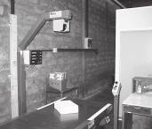
16 Chapter 3 Product description Operating Instructions VMS 100 Volume Measurement System VCM Main switch Connection for customer s Power supply VMC Fig. 3-2: View inside the VMC evaluation unit. The VMC is integrated inside a switching cabinet (not yet completely wired up in the picture). 3.2 The operating principle of the VMS 100 The VMS 100 Volume Measurement System determines the length, width and height of rectangular objects in any alignment on transport systems without contact and in real time. An optional input and output of separately determined information (e.g. bar-codes) can take place. The operating principle of the LMS The Laser Measurement System LMS scans a two-dimensional measurement area without contact. The LMS requires no reflectors or position marks. No illumination of objects is necessary as it is an active system with an infrared laser. Fig. 3-3: The LMS SICK AG Division Auto Ident Germany All rights reserved /

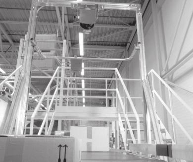
17 Operating Instructions Product description Chapter 3 VMS 100 The LMS operates according to the time-of-flight principle. The distance from the object to the system is determined from the time between the transmission of a light pulse and the reception of the light reflected by the object, as measured by the LMS. The operating principle of the VMC 100 The VMC 100 Laser Measurement Interface is based on the LMI 200. The LMI 200 is a multifunctional evaluation unit specially developed for processing LMS data. The LMI 200 can process and transmit, via digital and analogue interfaces, the process data obtained for various measurement commands. The MST 200 Measurement Software Tool is available for the development of customer-specific evaluation software. Fig. 3-4: The LMI 200. According to its configuration, the LMI 200 processes data supplied by the LMS 200 Laser Measurement System together with other information. These data are processed in real time and given out at the interfaces as measurement results. The operating principle of the VMS 100 An LMS 200 Laser Measurement System is installed above the transport system. It scans the surface of the transport system and the transported objects about every 13.3 ms. The distance data obtained by the LMS 200 are transferred to the VMC 100 in real time. The speed of the transported objects is set as a constant or can be provided using an optional shaft encoder. LMS Object Fig Sketch of the VMS 100 with its frame above the transport system / SICK AG Division Auto Ident Germany All rights reserved 17
18 Chapter 3 Product description Operating Instructions VMS 100 Volume Measurement System The three-dimensional information on the rectangular object is available after the distance data have been determined and the speed calculated in. The VMS program calculates the length, width and height of the rectangular object from the measurement data. Output of the data takes place at the VMC 100's selectable RS-232/RS-422 interface. VMS 100 layout The measurement data is made available at an RS-232/RS-422 interface. Connection to a data transfer system can take place via gateways or interface converters. A shaft encoder can be connected to the VMC 100. The VMC 100 can receive results from auxiliary devices (e.g. bar-code measurements) via the RS-485 interface and give them out in real time together with the dimensional data at the RS-232/RS-422 interface of the VMC 100. Please note: Customers require their own Windows NT/Windows 95 PC with RS-232 interface and a data cable (e.g ) for commissioning and parameter-setting. The following schematic diagram shows the components of the VMS 100. Commissionin PC + softwar VMS 100 RS-232 LMS 20 VMC software RS-232/-422 Host, converter for bus system, etc. optional RS-485 E.g. bar-code reader Switch E.g. scales Shaft encoder Fig. 3-6: Schematic diagram of VMS 100 components and peripheral devices. 18 SICK AG Division Auto Ident Germany All rights reserved /
19 Operating Instructions Product description Chapter 3 VMS Indicators and operating elements Operating elements Parameterisation of the VMS 100 takes place via the supplied VMS 100 Commissioning Software, installed on the PC by the customer. The VMS 100 can be operated with permanent or limited measurement readiness: With permanent measurement readiness objects are automatically detected and the data recorded. The object data is calculated and given out after the end of the object has been reached. - Automatic Mode With limited measurement readiness the next object is only automatically detected and the data recorded after activation. The object data is calculated and given out after the end of the object has been reached; the VMS 100 is then only ready for renewed measurement after reactivation. Activation can be carried out by: - a digital switch (falling flank), - a host telegram (renewed host request only after object measurement completed) Functions of the LED indicators Two LED indicators on the VMC 100 provide optical information on the operating state and errors. The LED indicators are located on the front panel. LED Indicator VMC 100 state POWER green switched on (DC 24V supplied) off switched off (no power supply) MODE green Measurement Mode active off Setup Mode 10% green blinking Service Mode 90% green blinking Measurement Mode is being activated red Software Download Mode (VMC 100 busy) green/red blinking Warning (e.g. front window contamination entered in error log), Measurement Mode is still acitve 1) red blinking VMC 100 error (error entered in error log) 1) 1) Run VMC 100 Diagnostics with User Software Table 3-1: VMC 100 LED indicators. Three LED indicators on the LMS 200 provide optical information on the operating state and errors. LED Normal operation Initialisation Contamination warning Contamination error Error Fatal error Green 100% on off off off off Yellow (1 Hz) off 100% on 50% on / 50% off 90% on / 10% off 10% on / 90% off 50% on / 50% off Red off 100% on on on on Table 3-2: LMS 200 LED indicators / SICK AG Division Auto Ident Germany All rights reserved 19
20 Chapter 3 Product description Operating Instructions VMS 100 Volume Measurement System 3.4 Requirements and measurement accurac Object requirements The VMS 100 is designed for determining the volumes of rectangular objects. Rectangular objects have straight sides with no curves or projections. The minimum and maximum object dimensions are summarised in the following table: Object dimension Minimum value Maximum value Length along direction of transport 200 mm 1500 mm to 7500 mm At right angles to direction of transport 200 mm 1500 mm Height on the transport system 100 mm 1500 mm Table 3-3: Minimum and maximum dimensions of rectangular objects. Please note: The maximum value for the dimension along the direction of transport is 1500 mm as standard. How the maximum value can be varied is described in Table 6-1 in 6.2 Setting para eters. The transport speed must be at least 0.1 m/s and at most 2 m/s. The time periods between objects must typically be: at least 1/10 of the maximum object dimension along the direction of transport. See following table. Object dimension along the direction of transport Gaps required between objects < 1000 mm 100 mm < 1500 mm 150 mm Table 3-4: Object gaps typically required. VMS 100 measurement accurac Typical levels of accuracy are provided in Table 3-5. Speed Speed < 1 m/s Typical accuracy ± 15 mm in length, width and height 1 m/s speed 2 m/s ± 25 mm in length ± 20 mm in width and height Table 3-5: Typical accuracy for an object with dimensions > 200 x 200 x 200 mm³ (L x W x H). The following accuracies apply at room temperature, with an object reflectivity of 10% to 1000% and for recommended device structures corresponding to SICK documentation. Restricted ranges for object reflectivity and object dimensions provide higher levels of accuracy. Highly reflective surfaces and other effects can lower accuracy. 20 SICK AG Division Auto Ident Germany All rights reserved /
21 Operating Instructions Product description Chapter 3 VMS 100 Speed Speed < 1 m/s Accuracy ± 30 mm in length, width and height 1 m/s speed 2 m/s ± 50 mm in length ± 35 mm in width ± 30 mm in height Table 3-6: Levels of accuracy for an object with dimensions > 200 x 200 x 200 mm³ (L x W x H). Transport system requirements The typical space requirement for installation of the LMS is about 1300 mm above the tallest object. The distance between the LMS and the upper surface of the tallest object must be at least about 700 mm, while a distance of about 1000 mm is recommended. Central mounting above the middle of the transport system is recommended, see Fig.3-2. If the objects are fed in at one of the transport system's sides mounting can be carried out asymmetrically above the transport system. LMS above the middle of the transport system LMS min. approx. 700 mm rec. approx mm Object maximum object height Fig. 3-7: Schematic diagram showing LMS 200 installation above a transport system. Objects can be moved using any transport system with a flat transporting surface. Rotation, vibration, rolling motion and slippage of objects on the transport system, or uneven transport surfaces, can reduce accuracy and have an adverse effect on data capture by the VMS. Curves, induction lines, start-stop sections, rising/falling sections and gaps in the transport system should be a sufficient distance from the measurement area for high accuracy and proper data capture. The LMS 200 must have a clear view of the transport system. The transport system must either have a constant transport velocity or a shaft encoder signal with a resolution of at least 1 Incr./mm must be installed, see 10.3 Available accessories (order details) / SICK AG Division Auto Ident Germany All rights reserved 21
22 Chapter 3 Product description Operating Instructions VMS 100 Volume Measurement System LMS 200 mounting requirements The LMS 200 must be mounted in such a way that it is: stable above the transport system (an LMS 200 unit weighs approx. 4.5 kg), shock-free and vibration-free, above the transport system. Fig. 3-2 shows an LMS 200 installation above the transport system with typical distances. Please note: The Mounting Set is easy to attach to an 8 mm item aluminium profile as it is designed for this profile. The dimensional drawing in Fig. 4-1 is to be complied with for mounting using other equipment. 3.5 Overview of commissioning 1. Mount the LMS 200 (see 4 Mounting). 2. Connect the LMS 200 to the VMC 100 with a data cable (see 5 Electrical installation). 3. Connect the LMS 200 to the VMC 100 with a power supply cable (see 5 Electrical installation). 4. Connect the power supply to the VMC 100 (see 5 Electrical installation). 5. Adjust the LMS 200 (see 4 Mounting). 6. Set VMS 100 parameters (see 6 Commissioning and parameter-setting). 22 SICK AG Division Auto Ident Germany All rights reserved /
23 Operating Instructions Mounting Chapter 4 VMS Mounting 4.1 Overview of the steps involved in mounting If necessary: mount the frame in the desired area of the transport system Attach the LMS Mounting Set to the frame or onto stable equipment Attach the LMS 200 to the Mounting Set Mount the VMC 100 evaluation unit 4.2 Preparing for mounting Prepare the components for mounting The LMS 200 Laser Measurement System The LMS 200 Mounting Set The VMC 100 evaluation unit Prepare the accessories The following accessories will be needed for the Mounting Set and LMS : Screws for attaching the Mounting Set to the frame or other equipment. The Mounting Set has 8xD6.6 drilled holes, see Fig The LMS 200 weighs approx. 4.5 kg Four M8x12 screws with washers (supplied) for attaching the LMS 200 to the Mounting Set Prepare mounting aids Plumbline Spirit level Measurement tape (up to 3000 mm) or folding metre-rule Scanfinder Pencil Tools, M6 screws Selecting the mounting location The VMS 100 is supplied with a power supply cable and data transfer cable that are each 10 m long. Select an appropriate mounting location for the LMS 200 and VMC / SICK AG Division Auto Ident Germany All rights reserved 23
24 Chapter 4 Mounting Operating Instructions VMS 100 Volume Measurement System Mounting accessories A Mounting Set is supplied for mounting the LMS 200. It can be finely adjusted in two axes. adjusting angle α adjusting angle β 40 Fig. 4-1: Dimensional drawing for Mounting Set with LMS 200 Measurements in mm. Total LMS 200 weight is approx. 4.5 kg. The angles are based on Fig Mounting the LMS 200 Fig. 4-2 shows the mounting of the LMS 200 from above the transport system. The angles α, β and γ are defined in Fig Direction of transport Object A LMS 200 Object B Object C Connection plug modules Fig. 4-2: Mounting of the LMS 200 from above the transport system. 24 SICK AG Division Auto Ident Germany All rights reserved /
25 Operating Instructions Mounting Chapter 4 VMS 100 LMS LMS LMS α Direction of transport Side view β Direction of transport View from above γ View in direction of transport Fig. 4-3: Definition of the LMS 200 angles During preparation ensure that the LMS 200 and the Mounting Set can be mounted horizontally to the trans- γ = 0. To align the LMS 200 above the middle of the transport area turn an M6 screw in the middle drilled hole at the base of the LMS 200 and attach the plumbline to it with the lead touching the transport system. Determine the middle of the transport area with transported objects on the transport system. Align the LMS 200 until the lead touches the middle of the transport area. 4.4 Mounting the VMC 100 The VMC 100 must be freely accessible so that the electrical supply and data cables can be connected. The VMC can be mounted on a standard mounting rail or the supplied bracket can be used. The VMC is supplied as a version with a switching cabinet. 4.5 Adjusting the LMS 200 Please note: Electrical installation (5 Electrical installation) must be completed before adjustment. Spatial alignment of the LMS Turn an M6 screw in the middle drilled hole in the base of the LMS 200. Attach the plumbline in such a way that it meets the end of the housing. 2. Turn the adjustment screw that is perpendicular to the direction of transport until the measurement line of the LMS 200 is located below the LMS 200 exactly 6.3 cm from where the plumbline meets the transport system in the direction of transport, see Fig Use the switched on Scanfinder to detect the measurement line (IR laser light). 3. Turn the adjustment screw that is in the direction of transport until the measurement line is on the transport system and perpendicular to the transport direction, see Fig For this purpose, use the switched on Scanfinder to detect the measurement line (IR laser light) on the left or right side of the transport system / SICK AG Division Auto Ident Germany All rights reserved 25
26 Chapter 4 Mounting Operating Instructions VMS 100 Volume Measurement System 63 mm Plumbline LMS 200 Measurement line Direction of transport Fig. 4-4: View from above the LMS 200 with plumbline and measurement line. Recommendation: Mount and adjust the LMS 200 carefully to achieve the highest levels of measurement value accuracy. 4.6 Dismantling the system 1. Switch off the power supply to the VMC 100 evaluation unit. 2. Remove the data cable, power supply cable and, if necessary, the clock-pulse cable from the VMC Remove the cables between the VMC 100 and the LMS 200 Laser Measurement System. 4. Remove the LMS 200 from the Mounting Set above the transport system. 5. Unscrew the VMC 100. In the final decommissioning follow the instructions in Chapter 7.3 Disposal for environmentally friendly disposal. 26 SICK AG Division Auto Ident Germany All rights reserved /
27 Operating Instructions Electrical installation Chapter 5 VMS Electrical installation 5.1 Overview of the installation steps Connect the VMC 100 to the LMS 200 (data transfer and power supply) Connect the VMC 100 with the higher-ranking destination computer (data transfer) Temporarily: connect the VMC 100 with a PC for commissioning, parameterisation and diagnostics 5.2 Electrical connections and cables The electrical connection of the VMS 100 consists of interfaces within the system and interfaces to the outside. LMS 200: Via 9-pin D-sub plug connections with plug modules: power supply (the "DC 24 V power supply" connection) a serial data interface (the "RS-422" connection) VMC 100: Via plug-in terminal strips and a 9-pin D-sub / 15-pin D-sub HD plug connection on the front panel: power supply (the "DC 24 V power IN" connection) power supply to LMS 200 (the "DC 24 V power OUT" connection) a data interface to the LMS 200 (the "RS-422 sensor" connection) four digital switching inputs (the "digital IN" connections) two inputs for shaft encoder signals (the "shaft encoder IN" connections) a data interface to higher-ranking destination computer or temporarily to PC (the "COM" connection) a data interface to connect optional devices (the "BUS" connection) The LMS 200 is connected to the VMC 100 via two pre-assembled cables each 10 m long. cable 1 (power supply): plug module with 9-pin D-sub socket (LMS 200) on 6-pin connector strip nos. 1-6 (VMC 100) cable 2 (data transfer): plug module with 9-pin D-sub plug (LMS 200) on 10-pin connector strip nos (VMC 100) / SICK AG Division Auto Ident Germany All rights reserved 27
28 Chapter 5 Electrical installation Operating Instructions VMS 100 Volume Measurement System 5.3 Pin configuration for the connections LMS 200 connections The "DC 24 V power supply" connection PIN Signal Function Cable colour 1 GND Ground Brow 2 New start - Blue 3 24 V DC Power supply Red 4 n.c OUT C Output C Grey 6 n.c n.c OUT B Output B Turquoise 9 OUT A Output A Orange Table 5-1: LMS 200: pin configuration on the 9-pin D-sub device plug. The "RS-422" connection (data interface) 5 1 PIN Signal RS-422 Function Cable colour 1 RxD- Receiver - Yello 2 RxD+ Receiver + Green TxD+ Transmitter + White 4 TxD- Transmitter - Brow 5 GND Ground/screen Black 6 n.c. - 7 bridged with PIN 8 Switches to RS bridged with PIN 7 Switches to RS n.c. - Table 5-2: LMS 200: pin configuration on the 9-pin D-sub device socket. 28 SICK AG Division Auto Ident Germany All rights reserved /

29 Operating Instructions Electrical installation Chapter 5 VMS VMC 100 connections Fig. 5-1 shows the location of the terminal strips and D-sub plug connections on the front panel. Fig. 5-1: VMC 100: position of the terminal strips and D-sub plug connections on the front panel. The VMC 100 is based on the LMI 200 and has the same plug connections. Terminal strips (functional interfaces) The terminal strips, with a total of 58 terminals, are organised in seven functional groups. Terminal VMC 100 connection VMC 100 signal Connected device signal Function 1 POWER DC 24V IN DC +24 V DC +24 V Power supply VMC POWER DC 24V IN GND GND Ground 3 POWER DC 24V OUT DC +24 V DC +24 V Power supply to LMS POWER DC 24V OUT GND GND Ground 5 POWER DC 24V OUT DC +24 V POWER DC 24V OUT GND SENSOR RS-422 (1) R+ T+ (pin 3, white) Data transfer to LMS SENSOR RS-422 (1) R- T- (pin 4, brown) Data transfer to LMS SENSOR RS-422 (1) T- R- (pin 1, yellow) Data transfer to LMS SENSOR RS-422 (1) T+ T+ (pin 2, green) Data transfer to LMS SENSOR RS-422 (1) GND GND (pin 5) Ground SENSOR RS-422 (2) ANALOGUE IN DIGITAL IN 1 (+) - - Photoelectric switch Q 22 DIGITAL IN 1 (ground) - - Ground / SICK AG Division Auto Ident Germany All rights reserved 29
30 Chapter 5 Electrical installation Operating Instructions VMS 100 Volume Measurement System Terminal VMC 100 connection VMC 100 signal Connected device signal Function 23 DIGITAL IN 2 (+) - - Photoelectric switch /Q 24 DIGITAL IN 2 (ground) DIGITAL IN 3 (+) DC +24V DC +24V Switch (optional: 'Digital Switch' Mode): measurement readiness on brief switching (falling flank min. 20 ms before object on measurement line) activate, no pallet 26 DIGITAL IN 3 (ground) GND GND Ground 27 DIGITAL IN 4 (+) DC +24V DC +24V Switch (optional: 'Digital Switch' Mode): measurement readiness on brief switching (falling flank min. 20 ms before object on measurement line), pallet height taken into account 28 DIGITAL IN 4 (ground) GND GND Ground 29 INCREMENT IN 1 (0 ) IN (+24V) +24V Shaft encoder 0 (optional) 30 INCREMENT IN 1 (90 ) IN (+24V) +24V Shaft encoder 90 (optional) 31 INCREMENT IN 1 (ground) GND GND Ground INCREMENT IN DIGITAL OUT 1 0 V bei AUS, + 24 V wenn aktiv 0 V bei AUS, + 24 V wenn aktiv Measurement readiness indicator (blinking: LMS error) 36 DIGITAL OUT 1 (ground) GND GND Ground DIGITAL OUT 2 as as DIGITAL OUT 3 as as DIGITAL OUT 4 0 V when OFF, + 24 V when active 0 V when OFF, + 24 V when active Measurement process active indicator (blinking: LMS error) 42 DIGITAL OUT 4 (ground) GND GND Ground DIGITAL OUT 5 as as DIGITAL OUT 6 as as DIGITAL OUT 7 0 V when OFF, + 24 V when active 0 V when OFF, + 24 V when active Indicator warning: object too long 48 DIGITAL OUT 7 (ground) GND GND Ground DIGITAL OUT ANALOGUE OUT 8 n.c. n.c. Table 5-3: VMC 100: Configuration of the plug-in terminal strips for VMS 100 functions. 30 SICK AG Division Auto Ident Germany All rights reserved /
31 Operating Instructions Electrical installation Chapter 5 VMS 100 "COM" connection (data interface) VMC 100 RS-232/RS-422 Connected device PIN RS-232 RS-422 RS-232 RS n.c. R- n.c. T- 2 RxD R+ TxD T+ 3 TxD T+ RxD R+ 4 n.c T- n.c. R- 5 GND GND GND GND 6 n.c. n.c. n.c. n.c. 7 n.c. Bridge to PIN 8 n.c. n.c. 8 n.c. Bridge to PIN 7 n.c. n.c. 9 n.c. n.c. n.c. n.c. Table 5-4: VMC 100: Pin configuration for the 9-pin D-sub device socket ("COM" connection). Communication parameter Baud rate Value 9600 bit/s Data bits 8 Parity none Stop bit 1 Table 5-5: LIM 200: "COM" data interface communication parameter values. Please note: After a configuration of the VMS 100 by means of the VMS 100 Commissioning Software the power supply to the VMC 100 evaluation unit must be briefly interrupted. After the restart interface parameters are set as shown in Table 5-5. The "BUS" connection (data interface) The RS-485 interface allows the input of additional information (e.g. bar-code or weight information) from the appropriate devices. Please note: The entire external telegram must be received by the VMC 100 while the object is crossing the measurement line. Table 5-6 shows the pin configuration. A termination resistance of 120 Ohms must be used on the receiver for cable lengths of more than 50 m / SICK AG Division Auto Ident Germany All rights reserved 31
32 Chapter 5 Electrical installation Operating Instructions VMS 100 Volume Measurement System VMC 100 PIN Signal RS-485 Connected device External device: e.g. bar-code scanner R- T- 12 R+ T+ 13 T- (R-) 14 T+ (R+) 15 GND GND Table 5-6: VMC 100: pin configuration for 15-pin D-sub HD device socket ("BUS" connection). The interface also operates with the communication parameters shown in Table Carrying out the electrical installation Data output takes place at the front panel via a 9-pin D-sub RS-232/RS-422 plug connection. The connection of further devices takes place at the front panel via a 15-pin D-sub RS485 plug connection. The data and power supply lines between the LMS 200 and VMC 100 are supplied with cabled LMS 200 plug modules and with VMC 100 plugs for connector strips for connecting the LMS 200 to the VMC 100. Connect the LMS 200 to VMC 100: 1. Connect data cable plug module to LMS Wire up the data cable connection strip to the connection strip and plug into the VMC 100 plug connection 3. Connect power supply plug module to LMS Wire up the power supply cable connection strip to the connection strip and plug into the VMC 100 socket Please note: Only operate the LMS 200 with correctly attached plug modules. Waterproofing is only guaranteed, with the device corresponding to IP65 and with EMC requirements (EMD) according to CE, when the plug modules have been completely mounted onto the scanner. The plug modules must be provided with locking screws or PG screws with seals and D-sub device plugs. 5. Connect the VMC according to Table 5-3 (PIN 1 and 2) or VMC to the power supply. The VMC 100 and LMS 200 commence operation after the power supply has been switched on. The start process can take a few minutes. The LMS 200 and VMC 100 are in an operating state when the green LEDs on both devices are lit. Adjustment of the LMS 200 (4.5 Adjusting the LMS 200) can take place after the electrical installation. 32 SICK AG Division Auto Ident Germany All rights reserved /
33 Operating Instructions Operation Chapter 6 VMS Commissioning and parameter-setting A PC with the Windows 95 TM or Windows NT TM operating system and an RS-232 interface and an RS-232 male/female-crossed data cable (see 10.3 Available accessories (order details)) is required for commissioning and parameter-setting. 6.1 Starting the VMS 100 Commissioning Software VMS 100 parameters are set using the VMS 100 Commissioning Software. The VMS 100 Commissioning Software is started on the PC. 1. Connect PC to the VMC 100 RS-232 COM interface with an RS-232 male/female-crossed data cable. 2. Insert the diskette with the VMS 100 Commissioning Software in diskette drive. 3. Copy files into their own directory on the PC. 4. Select and run the VMS100_Setup file using the Start menu. The VMS 100 Commissioning Software starts and opens a window labelled VMC 100 User Software for VMS 100. Recommendation: After commissioning keep the diskette with the VMS 100 Commissioning Software in a safe place to allow subsequent re-setting of parameters. 6.2 Setting parameters The VMS 100 can be parameterised after the VMS 100 Commissioning Software has been started. Click on the Parameters entry in the sub-menu VMS 100 in the Start menu. The menu window Parameters for the VMS 100 Volume Measurement System appears. The menu window is divided up into six sections and shows a schematic representation of the VMS 100. In the LMS/conveyor position Zone of detection Velocity Process Peripherics sections there are fields, some of which have pull-down menus, for entering parameter values. In the Controls section there are four buttons for operating and checking the menu window and for data exchange from the PC to VMC / SICK AG Division Auto Ident Germany All rights reserved 33

34 Chapter 6 Operation Operating Instructions VMS 100 Volume Measurement System Fig. 6-1: VMS 100 Commissioning Software: example of the Parameters for VMS 100 window. Please note: All parameters in the Parameters for the Volume Measurement System VMS 100 Vx.xx menu window must be entered as positive values. Close window with Exit. In order to achieve greater accuracy, it is recommended that parameters are reset if the LMS 200 is replaced Setting measurement area parameters Turn an M6 screw in the middle drilled hole in the base of the LMS 200 and attach the plumbline and let the lead weight touch the transport system. Note the distance to the left and right sides of the transport system from the lead weight, see Fig The measurement area is defined in the LMS/conveyor position section on the basis of the LMS 200 position. 1. Enter the distance to the left edge of the transport area from the lead weight of the LMS 200 in mm in the Left conveyor (mm) field. 34 SICK AG Division Auto Ident Germany All rights reserved /
35 Operating Instructions Operation Chapter 6 VMS Enter the distance to the right edge of the transport area from the lead weight of the LMS 200 in mm in the Right conveyor (mm) field. 3. Enter the height of the LMS 200 above the transport system in the Height LMS/conveyor (mm) field. Please note: No object other than the object to be measured may be detectable for the LMS 200 in the measurement area during Measurement Mode. LMS Detection zone Measurement area Object Height of detection line Fig. 6-2: Sketch of the measurement area and detection zone with the height of the detection line. The left/right limits of the measurement are to be entered in the Left/Right conveyor (mm) fields as seen when looking at the bottom of the LMS 200, and similarly for the detection zone Setting detection zone parameters The detection zone is defined in the Zone of Detection section. When ready for measurement a volume measurement is started as soon as an object enters the detection zone, see Fig The detection zone parameters must be at least 50 mm smaller on each side than the values of the measurement area. No objects except the target object may be present in the detection zone. 1. Enter the left limit of the detection zone in mm from the lead weight of the LMS 200 in the Left (mm) field. This value should not exceed the value in the Left conveyor (mm) field. 2. Enter the right limit of the detection zone in mm from the lead weight of the LMS 200 in the Right (mm) field. This value should not exceed the value in the Right conveyor (mm) field. 3. Enter the height of the detection line above the transport system in the Height Zo (mm) field. This switching limit allows objects with lower heights to be suppressed. The height of the detection line should be at least 50 mm and at most 200 mm / SICK AG Division Auto Ident Germany All rights reserved 35
36 Chapter 6 Operation Operating Instructions VMS 100 Volume Measurement System Setting velocity parameters Speed parameters are set are in the Velocity section. 1. Enter the transport speed in the Conveyor velocity (cm/min) field. The value is required if no shaft encoder is used. 2. Select whether a shaft encoder or a constant speed is to be used in the Incremental encoder field (the Peripherics section). 3. Enter shaft encoder resolution in the 1/1000 mm per increment field. The value is required if a shaft encoder is used. E.g., a 1000 entry means 1 mm/incr Setting process control parameters Parameters for process control are selected from pull-down menus in the Process section. Selection in the Send parcel data field is about whether the data is to be transmitted automatically at the end of every measurement and calculation (entry: End of parcel) or whether only the values for the last object are to be sent in response to a host request (entry: Host). A host telegram can call up the last measurement data repeatedly. Selection in the Trigger source field is about whether the start of a measurement should be triggered automatically (entry: Automatic), after a brief switching of the VMC 100 (entry: Digital Output), or after a host request (entry: Host). The Digital Output entry: by switching two different digital switches on the VMC 100 decisions can be made on when pallet height is to be taken into account for each object. The flanks of the switching signal must fall at least 20 ms before the object crosses the measurement line. The Host entry: the entire telegram must be received by the VMS 100 at least 20 ms before the object crosses the measurement line. A pallet height can be entered in the Spacer height field. The entry is only active with the Digital Output setting. The entry in the Scans sample field defines whether all the scans are to be used for determining volume. With the default setting All scan the maximum object length is 1500 mm at speeds of from 0.5 m/s to 2 m/s. Table 6-1 shows the possible maximum object lengths and speeds. At speeds of 0.5 m/s to 2 m/s: At maximum object lengths of 1500 mm: Entry in 'Scans sample' field Max. object length Entry in 'Scans sample' field Speed All scan 1500 mm All scan 0.50 m/s to 2.0 m/s 1/ mm ½ 0.25 m/s to 0.5 m/s 1/ mm 1/ m/s to 0.25 m/s 1/ mm ¼ 0.15 m/s to 0.25 m/s 1/ mm 1/ m/s to 0.15 m/s Table 6-1: Setting parameters for maximum detectable object lengths and possible speed ranges. If No is entered in the Length always > Width field it defines that the length along the direction of transport is provided. If Yes is entered, the length value provided is the length of the longest side of the object. Height output can be modified in the Height = Height max field. An entry of No provides the most accurate value for the height of the rectangular object. An entry of Yes can be selected to take the maxi- 36 SICK AG Division Auto Ident Germany All rights reserved /
37 Operating Instructions Operation Chapter 6 VMS 100 mum height value more into account at speeds of less than 0.5 m/s, which can result in the values provided being less accurate Setting optional device parameters The VMS 100 Commissioning Software is informed about the optional connectable devices in the Peripherics section. If a bar-code reader is connected to the RS-485 interface of the VMC 100 as an auxiliary device it must be defined in the Barcode reader field (entry of No if no bar-code reader is connected). The following time window is available for receiving bar-code telegrams: the telegram starts no earlier than 20 ms after the object has crossed the measurement line, the telegram ends no later than 20 ms after the object has left the measurement line. The Weighter type field is used to define whether one of the selectable weighing machines is connected to the RS-485 interface of the VMC 100 as an auxiliary device (the entry No Weighter is used when no scales are connected). This auxiliary device is contacted after the end of the object. Connection should be carried out by SICK Service. The Increm. encoder field is used to define whether a shaft encoder is used: No = no shaft encoder, Yes = operation with a shaft encoder. The Photocell field can be used to register an optional photoelectric switch at the VMS 100. Such a photoelectric switch should be installed perpendicular to the direction of transport directly above the measurement line of the LMS Data transfer The handling of parameterisation data is defined in the Controls section. The Get values button inserts the parameterisation data available in the VMC 100 into the menu window. Data previously entered in the menu window are deleted. The Default values button provides the fixed standard parameterisation data. These provide guidelines for a standard application. Data previously entered in the menu window are deleted. The Send values buttons transmits the data visible in the menu window to the VMC 100. Data previously available in the VMC 100 are deleted. The Exit button closes the menu window without triggering any data transfer. 6.3 Output of measurement data on the screen VMS 100 measurement values can be received on the PC in real time after starting the VMS 100 Commissioning Software. This display is useful for testing the parameterisation the display is not suitable for normal measurement operation. Click on the See Values entry in the sub-menu VMS 100 of the File menu. The Volume Measurement System 100 menu window appears. The menu window shows the measurement data and two buttons. Under Volume Measurement there is: the Length field showing the length of the object, the Width field with the width of the object, and the Height field showing object height / SICK AG Division Auto Ident Germany All rights reserved 37

38 Chapter 6 Operation Operating Instructions VMS 100 Volume Measurement System Furthermore, the results of any optional connectable devices are also displayed if available: the Weight field may show the weight of the object, the Barcode field may show the bar-code on the object. Display is limited to 15 characters. As regards the buttons: The Test Request button transmits a telegram for measurement readiness. The Exit button closes the window. Fig. 6-3: Display of measurement data, an example after a restart. 6.4 Completion and test measurements Log all the parameters in the commissioning log and save the document somewhere safe. Customers should select a typical measurement object for the test measurements, selecting the following properties: typical object surface material typical object surface colour typical object size Carry out several measurements with the object. Measure the object precisely with a measuring tape or metre-rule and note the values for its length, width and height, and compare them with the VMS 100 measurement values. If necessary, reset the parameters. The output of the object dimension along the direction of transport can be optimised with the parameters Conveyor velocity or 1/1000 mm per increment. The LMS/conveyor position parameter affects the output of the height and the object dimension across the direction of transport of the object.!!! " # re-adjusted to optimise object dimension values across the direction of transport. Recommendation: Parameterise and adjust the VMS 200 carefully to achieve high accuracies. 38 SICK AG Division Auto Ident Germany All rights reserved /
39 Operating Instructions Maintenance Chapter 7 VMS Maintenance 7.1 Maintenance during operation To retain maximum performance the LMS 200 Laser Measurement System needs a clean front window (reading window). A weekly front window contamination check is recommended in harsh operating environments (dust, grindings, damp, etc.), in particular. More frequent checks may be required depending on the conditions. Clean the LMS 200 housing every six months to ensure sufficient cooling. Contamination indicator: Depending on the degree of front window contamination the LMS 200 provides the following warnings by means of the yellow LED (middle) and red LED (left): LED behaviour Yellow LED blinks at rate of 1 Hz, 50% on and 50% off Yellow LED blinks at rate of 1 Hz, 90% on and 10% off. The red LED is continuously lit Meaning Warning: weak contamination. The LMS 200 can still be used in this condition. Contamination error: strong contamination. The LMS 200 is no longer capable of operation. Table 7-1: LMS 200: LED error indicators on contamination of the front window. Depending on the degree of front window contamination the VMC 100 also issues the following warning by means of the "MODE" LED: "MODE" LED behaviour Green / red blinking Red blinking Meaning Warning (weak contamination). Measurement Mode still active. Error (strong contamination). The VMC 100 is no longer capable of operation. Table 7-2: VMC 100: LED error indicators on contamination of the LMS front window. Cleaning the front window of the LMS 200: Damage to the front window! The front window is made of plastic. System performance can be reduced as a result of scratches and streaks on the front window. ATTENTION Use mild detergent without any powder. Avoid scratching and scouring movements. Clean the front window at regular intervals, e.g. with an anti-static glass cleaning liquid. Use a soft, nonfluffy cloth for cleaning. If necessary also clean the LED indicators of the LMS 200 and the front panel of the VMC / SICK AG Division Auto Ident Germany All rights reserved 39
40 Chapter 7 Maintenance Operating Instructions VMS 100 Volume Measurement System 7.2 Maintenance The VMS 100 operates without the need for maintenance. Any errors that crop up are reported by the system via the "MODE" LED on the front panel of the VMC 100 and by the output of the device status, separately for the LMS 200 and the VMC 100, in the measurement results. See also Table 7-2 and Chapter Functions of the LED indicators. Test measurement: A test measurement every month is recommended with a typical rectangular reference object with known dimensions. Measure the object several times with the VMS 100 and compare the values received with the known object dimensions. 7.3 Disposal Dispose of unusable or irreparable devices in an environmentally friendly manner after a final decommissioning: 1. Follow valid local waste disposal regulations. 2. Dismantle the housing. 3. Dismantle the electronic assemblies. 4. Remove the front window (LMS 200) and dispose of it for plastic recycling. 5. Remove the chassis and dispose of it for aluminium die cast recycling. 6. Dispose of the electronic assemblies as special waste. 7. Dispose of cable wiring for metal recycling SICK AG does not currently accept the return of devices that are unusable or irreparable. 40 SICK AG Division Auto Ident Germany All rights reserved /
41 Operating Instructions Troubleshooting Chapter 8 VMS Troubleshooting 8.1 Overview of possible faults and problems Mounting error The LMS 200 is not well aligned upon the object on the transport system The shaft encoder (optional) is wrongly sited Error in the electrical installation VMC 100 data interface (COM connection) wrongly wired Bad connection between LMS 200 and VMC Parameterisation error Functions not adapted to the conditions on site Trigger source wrongly selected Technical device limits not taken sufficiently into account Operating difficulties Object gap too small Device fault (hardware/software) 8.2 Monitoring signs of faults and problems The VMS 100 monitors itself during operation: After switching on the power supply the VMS 100 carries out a self-test before initialisation (loading of the parameter set and initialisation of the device functions) involving the testing of important hardware components. If the VMS 100 discovers a device fault during the self-test or during self-monitoring, the VMC 100 gives out appropriate numerical values in the measurement result output telegram for VMC 100 status and LMS 200 device status in a coded form. See Chapter VMC 100 status and LMS 200 device status. The red and yellow LEDs of the LMS 200 and the "Mode" LED of the VMC 100 signal the system's error state. See Chapter Functions of the LED indicators. 8.3 Identifying faults and remedying them The following aids are necessary for remedying the faults described in the table below: these Operating Instructions tools a measuring tape (up to 2000 mm) a digital measurement device (current / voltage measurements) a PC with VMS 100 Commissioning Software RS-232 data connection cable, e.g. order no / SICK AG Division Auto Ident Germany All rights reserved 41
42 Chapter 8 Troubleshooting Operating Instructions VMS 100 Volume Measurement System Problem Possible cause Remedial action VMC 100: "power" LED does not light VMS 100 has no power supply - Check the cables - Measure power supply VMC 100: "mode" LED blinks first green and then red/green VMC 100: "mode" LED blinks red/green Bad connection to LMS 200 The system is issuing a warning: e.g. LMS 200 front window contaminated Check cables Check the values for VMC 100 status and LMS 200 device status in the measurement results using the PC. See Chapter VMC 100 status and LMS 200 device status VMC 100: "mode" LED blinks red Device fault Run Diagnostics with software LMS 200: yellow LED blinks at rate of 1Hz (50% on and 50% off) LMS 200: yellow LED blinks at rate of 1Hz (90% on and 10% off). Red LED lit constantly Higher-ranking computer cannot receive measurement results Object is not detected Measurement result: data given out contains 9999, 9999, 9999 LMS 200 front window slightly contaminated. VMS 100 still ready for operation LMS 200 front window strongly contaminated. VMS 100 not ready for operation - VMC 100 data interface wrongly wired - Destination computer interface not adapted - Parameter value "Height above transport system selected too high - Trigger source wrongly selected - Problem with connection to LMS 200 Detection zone too large Clean LMS 200 front window. See Chapter 7.1 Maintenance during operation Clean LMS 200 front window. See Chapter 7.1 Maintenance during operation - Check wiring - Set communication parameters correctly - Enter the correct value - Select the right trigger source - Check connection Adapt detection zone Measurement result: data incorrect Object gap too small - Correct measurement area - Increase object gap Measurement result: dimension at right angles to direction of transport too small Measurement result: object height too small/large Measurement result: dimension of object along direction of transport is too small/large Measurement result: object length is always zero Table 8-1: Troubleshooting table. Parameter values for measurement area "left & right limits" too small Parameter value "height" is too large/small Parameter value "speed" or "increments/mm" is too large/small Incr. encoder option is activated, but no signal available Increase parameter values Correct the value Correct the value Deactivate Incr. encoder option or connect shaft encoder 42 SICK AG Division Auto Ident Germany All rights reserved /
43 Operating Instructions Troubleshooting Chapter 8 VMS SICK Support If a fault cannot be remedied by any of the above-mentioned measures, the VMS 100 may be defective. The system does not contain any components whose functionality can be restored by the user repairing them after a breakdown. Please contact your local SICK office or subsidary: The telephone and fax numbers are listed on the back page of these Operating Instructions. Please do not send in the device without contacting SICK Service / SICK AG Division Auto Ident Germany All rights reserved 43
44 Chapter 9 Technical data Operating Instructions VMS 100 Volume Measurement System 9 Technical data 9.1 Data sheet for the VMS 100 Volume Measurement System Type VMS 100 Read window (LMS ) Laser diode plastic, semi-circular IR light, 905 nm Laser protection class (LMS ) 1 (eye-safe), acc. to DIN EN Usable slit angle max. 180 Detectable object shape Min. object dimensions (L x B x H) Max. length x width x height Min. object gap Transport velocity Typ. accuracy (L, W, H) up to 1 m/s up to 2 m/s Optical indicators Data interface COM (VMC 100) Communication parameter Output data Data interface BUS (VMC 100) Communication parameter Functional switching inputs Functional switching outputs Electrical connections (VMC 100) rectangles 200 mm x 200 mm x 100 mm 7500 mm x 1500 mm x 1500 mm typ. > 100 ms m/s, constant or variable (shaft encoder required) with min. object size of 200 mm x 200 mm x 200 mm: ±15 mm, ±15 mm, ±15 mm ±25 mm, ±20 mm, ±20 mm LMS 200: 3 LEDs, VMC 100: 2 LEDs RS-232 or RS-422 (configurable) 9600 bits/s, 8 data bits, no parity, 1 stop bit length, width, height, optional: e.g. bar-code when bar-code scanner connected RS bits/s, 8 data bits, no parity, 1 stop bit 4 x digital DC 24 V, 2 x shaft encoder 24V / 100 max. KHz 3 x digital DC 24 V 7 connection strips, 1 x 9-pin D-sub socket, 1 x 15-pin D-sub HD socket Operating voltage/power consumption VMC : DC 24 ±15% / 56 W total VMC : AC 230 V -15%+10% / 50 Hz Housing LMS : die-cast aluminium; VMC : aluminium continuous cast profile, -0100: lacquered sheet steel, PC windo Protection class LMS : Class 2/ VMC : Class 2, acc. to DIN Enclosure rating (acc. to VDE 0106/IEC ) LMS : IP 65 VMC : IP 20, acc. to VDE 0106/IEC , VMC : IP 65 EMC test acc. to IEC 801, Part 2-4; EN / Vibration/shock tests LMS : acc. to IEC , Tab. 2c/ IEC , Tab. 2 VMC : acc. to DIN EN / DIN EN VMC : acc. to DIN EN Test FC/ DIN EN Test EA Weight LMS : ca. 4.5 kg, VMC : ca. 1.7 kg, VMC : ca. 11 kg Temperature (operating/storage) LMS : C/ C VMC : C/ C, 0100: C/ C Table 9-1: Technical specifications for the VMS SICK AG Division Auto Ident Germany All rights reserved /
45 Operating Instructions Technical data Chapter 9 VMS Dimensional drawings LMS Laser Measurement System dimensional drawing All dimensions in mm Fig. 9-1: Dimensions of the LMS Laser Measurement System / SICK AG Division Auto Ident Germany All rights reserved 45
46 Chapter 9 Technical data Operating Instructions VMS 100 Volume Measurement System VMC evaluation unit dimensional drawing max. 187 (variable distance) Mounting Set foot for standard mounting rail All dimensions in mm Fig. 9-2: Dimensions of the VMC evaluation unit 46 SICK AG Division Auto Ident Germany All rights reserved /
47 Operating Instructions Technical data Chapter 9 VMS View of Mounting Set for LMS Fig. 9-3: Structure of Mounting Set no / SICK AG Division Auto Ident Germany All rights reserved 47
48 Chapter 9 Technical data Operating Instructions VMS 100 Volume Measurement System View of VMC All dimensions in mm Fig. 9-4: Dimensions of the VMC evaluation unit. 48 SICK AG Division Auto Ident Germany All rights reserved /
49 Operating Instructions Appendix Chapter 10 VMS Appendix 10.1 Overview of the Appendix The appendix contains the following supplements and auxiliary information: Telegram structure System or component replacement Available accessories (order details) Information on supplementary documentation The EU Declaration of Conformity Index 10.2 Telegram structure Telegram format The telegram given out by the VMC 100 as the measurement result via its COM data interface, is composed as follows in Tab from the top downwards: Description Bytes Meaning Header 8 Header, beginning with ST Object length in mm 4 ASCII data Separator 1 09(hex) Object width in mm 4 ASCII data Separator 1 09(hex) Object height in mm 4 ASCII data Separator 1 09(hex) Object weight in kg 4 ASCII data Separator 1 09(hex) Bar-code length 2 ASCII data Separator 1 09(hex) Bar code n ASCII data Separator 1 09(hex) Device status 1 he VMC 100 status 1 he Checksum 2 CRC 16 Table 10-1: Telegram format at the COM data interface (VMC 100). The VMS 100 can receive an external telegram during Measurement Mode and integrate it in the output telegram. The entire external telegram must be received by the VMC 100 during the measurement of the object. A measurement is active while an object is on the measurement line. The structure of a telegram that can be sent from an auxiliary device to the RS-485 interface of the VMS 100, is defined as follows: / SICK AG Division Auto Ident Germany All rights reserved 49
50 Chapter 10 Appendix Operating Instructions VMS 100 Volume Measurement System Description Bytes Meaning Start characters 1 STX Number of characters in bar code Bar code Block check (BCC) 2 Separator, CL code length, before code (trigger for digital in: flank high) Length depending on application Block check, XOR linkage via all preceding characters (hex-ascii format) End characters 1 ETX Table 10-2: Structure of external telegrams VMC 100 status The VMC 100 device status transferred in the telegram has the following meaning: Code Meaning 0 Normal Measurement Mode 1 Warning: LMS window contaminated 2 Problem LMS Problem bar-code scanner 4 Problem weighing machine Table 10-3: Output telegram: meaning of the VMC 100 status LMS 200 device status In the LMS 200 status byte information is provided bit-wise. Bit Meaning 0-2 Classification: 0 = Normal Measurement Mode 1 = Information 2 = Warning 3 = Error 4 = Fatal error 3-4 Cause: 0 = Software VMC = Software VMS = LMS = Not used (reserved) 5 Contamination: 0 = None 1 = Contamination of LMS windo 6-7 Not used (reserved) Table 10-4: Output telegram: meaning of the LMS 200 device status. 50 SICK AG Division Auto Ident Germany All rights reserved /
51 Operating Instructions Appendix Chapter 10 VMS 100 Triggering measurement readiness with a telegram from the host: If the system is in "Limited measurement readiness" mode (Request) measurement readiness is activated by the following telegram to the VMC 100: D C F 56 See also the Test Request button in Fig. 6-3 in Chapter 6.3 Output of measurement data on the screen. The telegram shown above is sent to the VMC 100 by pressing this button. Request for measurement values with telegram from host The measurement values of the VMS 100 can be requested with the following telegram: D C A 56. The telegram can be sent to the VMS 100 several times for repeated requests Replacing a system or components Proceed as follows if the system or individual components need replacement: LMS 200: 1. Switch off VMC 100 power supply. 2. Loosen and remove the plug modules of both connection cables on the LMS Loosen and remove the Mounting Set screws on the LMS 200 and remove the device. 4. Mount and connect the replacement device appropriately. 5. Switch on the VMC 100 power supply. 6. Connect PC to the VMC 100 "COM" connection via the data cable and start up PC. 7. Start the VMS 100 Commissioning Software and completely reset the system parameters as described in Chapter 6. This ensures that a high level of measurement accuracy is also achieved with the new LMS 200. VMC 100: 1. Note all the parameters with the help of the Commissioning Software. 2. Switch off the VMC 100 power supply. 3. Remove all connection cables on the VMC Disassemble the VMC 100. Unscrew the VMC with its wall bracket from the base or unclip the VMC from the mounting rail. Or remove the VMC from the attachment equipment. 5. If necessary remove the VMC 100 from the wall bracket. 6. Mount the new device. First screw the new VMC onto the wall bracket and then together with it onto the base, or snap the device onto the mounting rail. Or mount the VMC-0100 onto the attachment equipment. 7. Re-attach all the connection cables to the VMC Switch on the VMC 100 power supply. 9. Connect the PC to the VMC 100 COM connection via the data cable and start the PC up. 10. Start the VMS 100 Commissioning Software and enter the parameters that were noted before with the parameterisation software or completely reset the system parameters as described in Chapter 6. See Chapter 7.3 Disposal for disposal of unusable or irreparable devices / SICK AG Division Auto Ident Germany All rights reserved 51
52 Chapter 10 Appendix Operating Instructions VMS 100 Volume Measurement System 10.3 Available accessories (order details) The complete VMS 100 systems Order no. Description The complete VMS system, consisting of: - 1 LMS Laser Measurement System - 1 Connection Set 2 for the LMS 200: 2 cables for electrical supply and data transfer, each 10 m long, with one connection plug module each for the LMS Mounting Set, two-axis, fine adjustment - 1 VMC evaluation unit with installed VMS 100 Evaluation Software, for clip-on mounting rail, with a mounting set for wall mounting - 1 diskette (3½ inch) with VMS 100 Commissioning Software for Windows-NT/Windows 95 Table 10-5: Order details: the complete VMS 100 system. Also available on request as a device version, with VMC in an IP 65 protective cabinet with power supply Accessories Optional accessories for operation: Order no. On request On request On request On request On request Description Photoelectric switch Shaft encoder, resolution min. 1 mm Bar-code scanner Power supply unit Adapter for connection to Bus systems Heating plate for LMS 200 for operation between 12 C C, though no LMS operation outdoors 230 VAC ± 10 %, 30 W (cyclic, thermostat-controlled), IP 65 Table 10-6: Order details: optional accessories for operation. Accessories for commissioning: Order no. Description Data cable for connection of PC/Laptop to VMC 100, with 2 x 9-pin D-sub plugs, length 3 m (RS-232 male/female-crossed) Scan finder Table 10-7: Order details: optional accessories for commissioning. 52 SICK AG Division Auto Ident Germany All rights reserved /
 Proctective conductor Connection cable (shown without terminal compartment cover with PG 9 cable) ATTENTION!")
53 Operating Instructions Appendix Chapter 10 VMS View of the accessories Heating plate Connection of the heating plate 230 V AC ± 10 % 1) Proctective conductor Connection cable (shown without terminal compartment cover with PG 9 cable) ATTENTION! Proctective conductor must be connected. 1) Connection cable: wire cross-section up to 1.5 mm 2 Fig. 10-1: Structure and electrical connection of the heating plate no Supplementary documentation Order no. Title Technical Description "LMS ", German Technical Description "LMS ", English Technical Description "LMI 200", German Technical Description "LMI 200", English Operating Instructions "LMI 200 User Software", German Operating Instructions "LMI 200 User Software", English Technical Description "MST LMI 200 version, German/English Table 10-8: Supplementary documentation / SICK AG Division Auto Ident Germany All rights reserved 53
Video Media Center - VMC 1000 Getting Started Guide
 Video Media Center - VMC 1000 Getting Started Guide Video Media Center - VMC 1000 Getting Started Guide Trademark Information Polycom, the Polycom logo design, Video Media Center, and RSS 2000 are registered
Introduction 2. Other Applicable Documents 2. Scope of Delivery 3. Attaching the Snap-on Ferrite Suppressor 4
 H-206.F2 6-Axis Precision Alignment System Contents Introduction 2 Other Applicable Documents 2 Scope of Delivery 3 Attaching the Snap-on Ferrite Suppressor 4 Connecting the Hexapod to the C-887 with the
Programmable Safety Systems PSS-Range
 Programmable Safety Systems PSS-Range PROFIBUS-DP for Compact 3rd Generation PSS Operating Manual Item No. 20 962-04 All rights to this manual are reserved by Pilz GmbH & Co. KG. Copies may be made for
Primrose Awnings Full Cassette Manual & Electric Instructions
 Primrose Awnings Full Cassette Manual & Electric Instructions Contents for Full Cassette Awning 1 x Remote control receiver box 2 x Remote hand-held zappers 1 x 5 metre cable 1 x Template sticker **The
Please read this guide carefully. It tells you how to prepare your cutting plotter for production use in a few easy steps.
 OPERATING GUIDE for Secabo mini Cutting Plotter Congratulations on purchasing your Secabo mini cutting plotter! Please read this guide carefully. It tells you how to prepare your cutting plotter for production
Primrose Awnings - Full Cassette Manual & Electric Instructions
 Primrose Awnings - Full Cassette Manual & Electric Instructions Contents Warning 2.0m - 3.5m Awnings 8 x Expansion bolts ** 2 x brackets 1 x Awning 1 x Winder 4.0m - 5.0m Awnings 12 x Expansion bolts **
Primrose Awnings Half Cassette Manual & Electric Instructions
 Primrose Awnings Half Cassette Manual & Electric Instructions Contents for 2.5m, 3m Awnings 4 x Expansion bolts (2 per bracket)** 2 x brackets 1 x Awning Contents for 3.5m, 4m Awnings 6 x Expansion bolts
Primrose Awnings Half Cassette Manual & Electric Instructions
 Primrose Awnings Half Cassette Manual & Electric Instructions Contents Contents for 2m, 2.5m, 3m Awnings 2 x wall brackets 4 x expansion bolts (2 per bracket)** 1 x Awning Contents for 3.5m, 4m and 4.5m
quick and easy installation guide
 www.directdriveopener.com quick and easy installation guide Back 2 Front. Motor Carriage 2. C-rail. Chain. Limit stops. Slide in part (tensioner) Rail assembly Insert C-rail parts () into the connecting
NORTHFIELD CORPORATION 1870 COMMERCE DR. DE PERE, WI UNITED STATES
 1 MANUFACTURER: MODEL: NORTHFIELD CORPORATION 1870 COMMERCE DR. DE PERE, WI 54115 UNITED STATES NORTHFIELD CLS SPECIFICATIONS: VOLTAGE: FREQUENCY: CURRENT: AIR: 115VAC-230VAC 50/60Hz 5 AMP 80 PSI (for
TRUMPF TRUMATIC L 3050
 TRUMPF TRUMATIC L 3050 CNC laser cutting machine Manufacturer TRUMPF Model TRUMATIC L 3050 Year of manufacture 2004 Control Machine number Travels SIEMENS SINUMERIK 840 D A0230A0580 X 3.000 mm / Y 1.500
General-Use Auto-Tuning HPX-T Series
 General-Use Auto-Tuning HPX-T Series Built-in Hyper-tuning automatically adjusts scanning characteristics. Adjustment steps, results and scanning conditions are digitally displayed by LED. Digital display
Retractable Hose Reel
 Retractable Hose Reel installation and Operation Please read before use We recommend keeping these instructions for future reference Hose Reel must be mounted before use Keep the hose retracted when not
Cassette-folding arm-awning markilux 990
 Cassette-folding arm-awning markilux 990 Mounting instructions 1. Overview 1 Projection profile 2 Folding arm 3 Fabric 4 Console 5 Cassette 6 Covering cap 7 Wall bracket 2. Mounting brackets 2.1 Overview
Quick Start Guide 3500 AquaVent
 Quick Start Guide 3500 AquaVent Please read this document carefully before using the AquaVent. High Quality Groundwater and Surface Water Monitoring Instrumentation Note: For information on using your
Product information Truma VarioHeat and E-Kit. July 2018
 Product information Truma VarioHeat and E-Kit July 018 Truma VarioHeat The new compact Truma heaters for motor homes, caravans and vans. Truma VarioHeat eco and Truma VarioHeat comfort are of an identical
Power Relay RCE. Ordering Information. A High-capacity, High-dielectric-strength Relay Compatible with Momentary Voltage Drops
 Power Relay A High-capacity, High-dielectric-strength Relay Compatible with Momentary Voltage Drops No contact chattering for momentary voltage drops up to 0% of rated voltage. Wide-range AC-activated
6275-S1 PNEUMATIC DRILL OPERATING MANUAL ORIGINAL INSTRUCTIONS. P/N November 2014 Revision 1
 6275-S1 PNEUMATIC DRILL OPERATING MANUAL ORIGINAL INSTRUCTIONS P/N 80749 November 2014 Revision 1 2014 Climax Portable Machining and Welding Systems or its subsidiaries. All rights reserved. Except as
Mounting Type Contact form Quick-connect Screw terminals PCB terminals. E-bracket SPST-NO G7L-1A-T G7L-1A-B
 A High-capacity, High-dielectricstrength Relay Compatible with Momentary Voltage Drops No contact chattering for momentary voltage drops up to 0% of rated voltage. Wide-range AC-activated coil that handles
Installation instruction
 Installation instruction Ci51 116 FACTS Technical specifications Model i51 Log box (option) Output 6-11 kw Nominal output 8 kw Efficiency 80 % Weight (kg) 215 50 Powerstone (option): + 100 kg Width (mm)
VERTICAL BLINDS AND CONSERVATORY AWNINGS safe timeless beautiful. markilux Technical Information. markilux
 VERTICAL BLINDS AND CONSERVATORY AWNINGS safe timeless beautiful markilux Technical Information www.markilux.com markilux markilux Technical Information VERTICAL BLINDS AND CONSERVATORY AWNINGS The installation
Emergency Stop Devices
 New! Selection and Application of.. 278 Emergency Stop Rope Pull Switches........... 279 New! Emergency Stop Push Buttons............... 293 Banner Engineering Corp. Minneapolis, MN U.S.A. bannerengineering.com
HardSID Uno / UPlay user s guide HardSID Uno HardSID UPlay
 HardSID Uno / UPlay user s guide HardSID Uno HardSID UPlay HardSID Uno / UPlay user s guide 2010 Hard Software, Hungary 1 Safety information... 4 Introduction:... 5 Package contents... 5 System requirements...
User manual for awning blind AMZ Z-Wave
 GB User manual for awning blind AMZ ZWave Contents 1. Safety standards...2 2. Description...3 3. Programming the appliance...4 4. Association Groups...5 5. Compatibility of other producers appliances in
jointed arm awning _EN
 jointed arm awning TRENDLINE SUNBOX MOUNTING INSTRUCTIONs 930101_EN jointed arm awning TRENDLINE SUNBOX mounting instructions Contents Page 1. Safety 1.1 Explanation of the safety notes...3 1.2 General
Maintenance Instructions and Directions for Use Wind Support
 Maintenance Instructions and Directions for Use Wind Support Attention Important guidelines for end users Please read carefully and bear in mind before using! These instructions must be kept by the end
Hiway Gateway Specification and Technical Data
 L Hiway Gateway Specification and Technical Data HG03-400 8/92 detergant coffee chocolate Page 2 TDC 3000 Hiway Gateway Specification and Technical Data Introduction This publication defines the significant
Supplementary protector S 200 MR for ring-tongue applications acc. to UL 1077
 Electrical installations in buildings for ring-tongue applications acc. to UL 1077 S 200 MR is a high-performance supplementary protector with ring cable lug connections conforming to UL, CSA, and IEC
INSTRUCTION MANUAL ALEKO RETRACTABLE AWNING
 INSTRUCTION MANUAL for ALEKO RETRACTABLE AWNING www.alekoproducts.com FAILURE TO FOLLOW THESE INSTRUCTIONS MAY RESULT IN PERSONAL INJURY! 1 Important Safety Precautions WARNING NOTE: FOR PERSONAL SAFETY,
Model Crosspoint Matrix
 Model 3000 4380 256 Crosspoint Matrix 90401270 Page 1 All technical data and specifications in this publication are subject to change without prior notice and do not represent a commitment on the part
Please read this guide carefully. It tells you how to prepare your cutting plotter for production use in a few easy steps.
 OPERATING GUIDE for Secabo C30 and C40 cutting plotters Congratulations on purchasing your Secabo cutting plotter! Please read this guide carefully. It tells you how to prepare your cutting plotter for
TUCSON PATIO AWNING INSTALLATION MANUAL
 TUCSON PATIO AWNING INSTALLATION MANUAL Toll Free 877-792-1775 Fax 877-792-0031 swsuncontrolpro.com sales@swsuncontrol.com 1 INTRODUCTION...3 1.1 Symbols used in this manual... 3 1.2 Personnel requirements...
CASM electric cylinders The modular electric cylinder system
 CASM electric cylinders The modular electric cylinder system CASM electric cylinders are ideally suited to performing fast and powerful linear movements. Unlike pneumatic or hydraulic cylinders, CASM electric
TRT800 ATC Transponder Mode A, A-C, S P/N 800ATC-(1XX)-(1XX) Operation Manual. Document No.: e Revision 1.00 Datum:
-(1XX) Operation Manual. Document No.: e Revision 1.00 Datum:") TRT800 ATC Transponder Mode A, A-C, S P/N 800ATC-(1XX)-(1XX) Operation Manual Document No.: 03.2101.010.11e Revision 1.00 Datum: 19.04.2006 Gewerbestraße 2 86875 Waal phone: 08246 / 96 99-0 fax: 08246
TRT800 ATC Transponder Mode A, A-C, S P/N 800ATC-(1XX)-(1XX) Operation Manual Document No.: 03.2101.010.11e Revision 1.00 Datum: 19.04.2006 Gewerbestraße 2 86875 Waal phone: 08246 / 96 99-0 fax: 08246
Installation and Maintenance Manual
 Freestanding Gas Stove MODEL: PGS2005 GPEBB20R GPEBW20R Installation and Maintenance Manual Warning Maintenance products should be carried out by professional and technical personnel with relevant qualification,
For full product information, visit Use the SpeedSpec Code or scan the QR Code for quick access to the specific web page.
 R Safety Interlock Switches TL4024 Safety Interlock Switch with uard Door Locking High locking force of 1,500 N (7 lb.) locks guard door shut until machine is safe to enter IP67 (NEMA 6) enclosure withstands
Therme storage water heater. Table of contents. Symbols used. Symbols used Symbol indicates a possible hazard. Installation instructions
 Therme storage water heater Table of contents Symbols used... 8 Installation instructions Water supply... 9 Choice of location... 9 Installation of the Therme... 9 Fitting the draining and venting valve...
NEWMAR SERVICE SCHOOL
 NEWMAR SERVICE SCHOOL TRAINING INFORMATION GUIDELINE FOR FEBRUARY 2013 OUR PRODUCTS: NOVA DUAL PITCH AWNING G-2000/ G-1500 2 P a g e G-2085 G-5000 3 P a g e G-LINKS 4 P a g e NOVA/ G-2000/ G-1500 BASIC
Display Systems. 1. General. A. Multi-Function Display (MFD) B. Primary Flight Display (PFD)
 B. Primary Flight Display (PFD)") CIRRUS AIRPLANE MAINTENANCE MANUAL Display Systems CHAPTER 31-60: DISPLAY SYSTEMS GENERAL 31-60: DISPLAY SYSTEMS 1. General This section covers those systems and components which give visual display of
CIRRUS AIRPLANE MAINTENANCE MANUAL Display Systems CHAPTER 31-60: DISPLAY SYSTEMS GENERAL 31-60: DISPLAY SYSTEMS 1. General This section covers those systems and components which give visual display of
C-887.MC Hexapod Control Unit
 Technical Note KSch, C-887.MC Hexapod Control Unit System Description The C-887.MC Hexapod control unit is designed to be used with Hexapod systems which comprise a C-887 Hexapod controller. Using the
Optional Controls (Depends which set was purchased) Set A (Remote control kit)
 Set A (Remote control kit)") Primrose Awnings - Full Cassette Manual & Electric Instructions Contents Warning 1.5m - 3.5m Awnings 8 x Expansion bolts ** 2 x brackets 1 x Awning 1 x Winder 4.0m - 5.0m Awnings 12 x Expansion bolts **
Primrose Awnings - Full Cassette Manual & Electric Instructions Contents Warning 1.5m - 3.5m Awnings 8 x Expansion bolts ** 2 x brackets 1 x Awning 1 x Winder 4.0m - 5.0m Awnings 12 x Expansion bolts **
Power Supplies 3. SVL Essential DIN Rail Series. Phone: Fax: Web: -
 SVL Essential DIN Rail Series SVL Series power supplies are perfect for high volume, controlled environment applications where essential features are the only requirement. When space inside an enclosure
Contents. Awnings USA - Full Protective Hood Manual Instructions ft 11" - 11ft 6" Awnings
 Awnings USA - Full Protective Hood Manual Instructions Contents Warning We recommend that two or more people are required to lift the awning into place. 4ft 11" - 11ft 6" Awnings 8 x Expansion bolts **
Blue Series Hot Melt Hose with RediFlext II Hanger System
 Instruction Sheet P/N 1124594_01 Blue Series Hot Melt Hose with RediFlext II Hanger System Safety WARNING! Allow only personnel with appropriate training and experience to operate or service the equipment.
Hammer, Discus, Shot Put, Javelin
 Hammer, Discus, Shot Put, Javelin Competition Aluminium Discus And Hammer Cage 7/10 M Order No. 30290 Order No. 30290 D (Double Net) Order No. 30290 DS (Dismantle to fit a 20 container) Competition aluminium
Installation and User s Manual 12 x 10 MOTORIZED AWNING
 12 x 10 MOTORIZED AWNING Installation and User s Manual 12 x 10 MOTORIZED AWNING 088-1763-0 Stop Please read and understand this manual before any assembly or use of this product. Before beginning assembly
TCWS54 SEE THRU DIAMOND BURNER INSTALLATION KIT INSTRUCTIONS
 INSTALLER: Leave this manual with the appliance. CONSUMER: Retain this manual for future reference. These instructions are supplementary to the Installation and Operating Instructions supplied with the
PHY 133 Lab 6 - Conservation of Momentum
 Stony Brook Physics Laboratory Manuals PHY 133 Lab 6 - Conservation of Momentum The purpose of this lab is to demonstrate conservation of linear momentum in one-dimensional collisions of objects, and to
AWNING CONTROL KIT 98GCK-33B
 AWNING CONTROL KIT 98GCK-33B REV.07282015 RV AWNING PRODUCTS 1361 CALLE AVANZADO, SAN CLEMENTE, CA 92673 (800) 382-8442 FAX (949)276-5500 www.girardrv.com AC MOTOR CONTROL MODULE GC274B INSTALLATION and
S E L E C T I O N. Abdominal Crunch. User manual
 and S E L E C T I O N T H E S T R E N G T H E V O L U T I O N User manual and and The identification plate of the and manufacturer, affixed along side the seat on the frame of the weight stack, gives the
Installation manual. Awning. V480 Cannes
 Installation manual Awning V480 Cannes Installation manual awning V480 Cannes Content 1. Awning * 2. Wall supports 3. Extra support(s) (with an awning bigger than 350 cm) 4. Mounting plates (optional)
For full product information, visit Use the SpeedSpec Code or scan the QR Code for quick access to the specific web page.
 R Courtesy of CMA/Flodyne/Hydradyne Motion Control Hydraulic Pneumatic Electrical Mechanical (800) 6-5480 www.cmafh.com Safety Interlock Switches TL19 Safety Interlock Switch with uard Door Locking High
Pelican AMR Gateway User Guide
 Pelican AMR Gateway User Guide Document Reference: 8194 June 2016 Version: 2 Version Date Author Changes Number 1 Feb 2014 Bettina Rubek-Slater 2 Jun 2016 Sam Smith Branding updated API section updated
Lab Skills: Introduction to the Air Track
 Lab Skills: Introduction to the Air Track 1 What is an air track? An air track is an experimental apparatus that allows the study of motion with minimal interference by frictional forces. It consist of
Manual for External Batch/Screw Counter (NEX-PLC) for Screw Feeder FM-36
 for Screw Feeder FM-36") Manual for External Batch/Screw Counter (NEX-PLC) for Screw Feeder FM-36 1.Summary This counter can interface with Screw Feeder FM-36 by setting the number of batches/screws, to be fed, directly into this
Manual for External Batch/Screw Counter (NEX-PLC) for Screw Feeder FM-36 1.Summary This counter can interface with Screw Feeder FM-36 by setting the number of batches/screws, to be fed, directly into this
TECHNICAL INFORMATION
 TECHNICAL INFORMATION ISO 900 Certification was achieved in December 997, and reflects the strict adherence to quality management techniques from the first day of production. This certification was given
Safety Interlock Switches
 r Safety Interlock Switches TL19 TL19 Safety Interlock Switch with uard Door Locking High locking force of 10 N (270 lb.) locks guard door shut until machine is safe to enter IP67 (NEMA 6) enclosure enables
Solera Power Awning OEM INSTALLATION MANUAL
 Solera Power Awning OEM INSTALLATION MANUAL TABLE OF CONTENTS System Information 2 Safety 2 Prior To Installation 2 Resources Required 2 Awning Rail Installation (If Needed) 3 Installation 3 Awning Installation
Conservatory awning W8 Description
 1 3 4 Application Large-area external sun shading system for shading glazed conservatories, patio roofs and pergolas with flat pitch roofs. Function principle: tensioning system via toothed belt with steel
Optional Controls (Depends which set was purchased) Set A (Remote control kit)
 Set A (Remote control kit)") Primrose Awnings - Half Cassette Manual & Electric Instructions Contents Warning 1.5m - 3.0m Awnings 4 x Expansion bolts (2 per bracket)** 2 x brackets 1 x Awning 1 x Winder handle 3.5m - 4.0m Awnings
Primrose Awnings - Half Cassette Manual & Electric Instructions Contents Warning 1.5m - 3.0m Awnings 4 x Expansion bolts (2 per bracket)** 2 x brackets 1 x Awning 1 x Winder handle 3.5m - 4.0m Awnings
USER MANUAL. Tavor 8-T Active Ceiling Speaker MODEL: P/N: Rev 4
 KRAMER ELECTRONICS LTD. USER MANUAL MODEL: Tavor 8-T Active Ceiling Speaker P/N: 2900-300343 Rev 4 Contents 1 Introduction 1 2 Getting Started 2 2.1 Achieving the Best Performance 2 2.2 Safety Instructions
markilux 8800 / 8800
 VERTICL BLINDS ND CONSERVTORY WNINGS safe timeless beautiful markilux 8800 / 8800 Form follows function the timelessly modern conservatory awning with contrasting shapes designed down to the last detail
TANK MONITOR MODEL # (12V DC) (24V DC) (32V DC) OPERATION AND INSTALLATION INSTRUCTIONS
 (24V DC) (32V DC) OPERATION AND INSTALLATION INSTRUCTIONS") TANK MONITOR MODEL # 1510012 (12V DC) - 1510024 (24V DC) - 1510032 (32V DC) OPERATION AND INSTALLATION INSTRUCTIONS WARNING: Raritan Engineering Company,Inc.recommends that a qualified person install this
TANK MONITOR MODEL # 1510012 (12V DC) - 1510024 (24V DC) - 1510032 (32V DC) OPERATION AND INSTALLATION INSTRUCTIONS WARNING: Raritan Engineering Company,Inc.recommends that a qualified person install this
630 to 1800 A. Functions. Conformity to standards. General characteristics. Fuse combination switches SIDERMAT combination.
 SIDERMAT combination 630 to 1800 A sdmat_048_a_1_cat SIDERMAT combination are manually operated tri- or tetrapolar fuse disconnecting switches which can be triggered remotely. They provide breaking and
Smallest Connector with Removable Contacts
 1 Ultra-Miniature 8STA Size 01 Connectors Smallest Connector with Removable Contacts Ultra compact design and very lightweight connector dedicated to the harshest of motorsport environments. Innovative
10 A at 100 to 240 VAC. G3NE-220T-US (20 A at 75 to 264 VAC) 5 A at 100 to 240 VAC
 5 A at 100 to 240 VAC") Solid State Relays G3NE Compact, Low-cost, SSR Switching 5to20 A Wide load voltage range: 75 to 264 VAC. Dedicated, compact aluminum PCB and power elements used. Built-in varistor effectively absorbs external
Solid State Relays G3NE Compact, Low-cost, SSR Switching 5to20 A Wide load voltage range: 75 to 264 VAC. Dedicated, compact aluminum PCB and power elements used. Built-in varistor effectively absorbs external
CASM electric cylinders
 CASM electric cylinders 2 The modular electric cylinder system CASM electric cylinders are ideally suited to performing fast and powerful linear movements. Unlike pneumatic or hydraulic cylinders, CASM
markilux 8850 Round, square, flexible the designer conservatory awning with indented guide tracks for bevel-edged conservatories
 VERTICL BLINDS ND CONSERVTORY WNINGS safe timeless beautiful markilux 8850 Round, square, flexible the designer conservatory awning with indented guide tracks for bevel-edged conservatories rated to wind
Trapped Key Transfer System SHGV SVM SVE
 Trapped Key Transfer System SHGV SVM SVE Description Area of application Cost Savings The SHGV key transfer system occurs mainly in more complex manufacturing systems and equipment. It is especially suitable
Tank. Part B, Section 1. This section covers the following unit configurations. Pump Piston Pump (E or G)
") Part B, ection Model Voltage This section covers the following unit configurations. 3400V All Pump Piston Pump (E or G) Manifold Control 4-Port (A) Vista tandard (V) Vista Pattern (PC) Vista Temperature
Part B, ection Model Voltage This section covers the following unit configurations. 3400V All Pump Piston Pump (E or G) Manifold Control 4-Port (A) Vista tandard (V) Vista Pattern (PC) Vista Temperature
INSTALLATION GUIDE INTRODUCTION
 INSTALLATION GUIDE for for HotEdge Rail Rail INTRODUCTION HotEdge Rail is a patent pending one-piece roof edge ice melt systems engineered to easily install on standing seam, pro panel, and corrugated
Primrose Awnings - Standard Manual Instructions
 Primrose Awnings - Standard Manual Instructions Contents Warning 1.5m - 3.0m Awnings 4 x Expansion bolts (2 per bracket)** 2 x brackets 1 x Awning 1 x Winder handle 3.5m - 4m Awnings 6 x Expansion bolts
RAFTER VI. Installation and Operation CAREFREE WITH AUTOMATIC AWNING SUPPORT. RV Accessory PRODUCT OVERVIEW
 CAREFREE RAFTER VI RV Accessory WITH AUTOMATIC AWNING SUPPORT Installation and Operation PRODUCT OVERVIEW The gives the awning user the ability to easily tighten the center fabric when the awning is extended.
Accessories for Central Inverters SERVICE TENT
 Accessories for Central Inverters SERVICE TENT Installation Guide SCxxxCPZelt-eng-IUS103910 98-4044710 Version 1.0 CA US Legal Restrictions Copyright 2012. All rights reserved. No part of this document
12V DIRECT RESPONSE. Installation Manual
 CAREFREE 2V DIRECT RESPSE Installation Manual AUTO-RETRACT SYSTEM The 2V Direct Response Auto-Retract System may be installed as part of the original motorized awning installation or as an upgrade to an
The MiniTower GOTO AltAz Mount with GPS and dual Mount set-up #8300
 The MiniTower GOTO AltAz Mount with GPS and dual Mount set-up #8300 FEATURES 25 lb Payload 8 lbs of additional payload on the balancing side All metal (aluminum alloy and stainless steel) heavy duty tripod
B 600. Automatic grinding and polishing machine
 B 600 Automatic grinding and polishing machine B 600 Automatic grinding and polishing machine The sharpness, cutting edge angle, shape and profile of a cutter knife have a large impact on the quality of
SPEDESTER Series QUICK REFERENCE GUIDE
 Spedester series Digital DC Drives come with an extensive range of standard software blocks, it can take control of the most demanding motion control tasks. Designed for industrial applications, Spedester
MS201E H-840 Hexapod Microrobot. User Manual. Version: Date:
 MS201E H-840 Hexapod Microrobot User Manual Version: 2.0.0 Date: 25.07.2017 This document describes the following products: H-840.G2 Hexapod Microrobot, Gearhead, 2.5 mm/s, 30 kg Load, Sub-D Connector,
Parts Catalog. Slicing Machine G10. Model:
 , 07 995079 ECN 96 Parts Catalog Slicing Machine G0 Model: G0 /8/7N Rev. E, Serial Number 4048 and Up IMPORTANT! TO EXPEDITE SHIPMENT OF PARTS, ALWAYS SPECIFY MODEL, REV, PART NUMBER, AND SERIAL NUMBER
ECLIPSE USER MANUAL AMXMAN REV 2. AUTOMETRIX, INC. PH: FX:
 ECLIPSE USER MANUAL AMXMAN-12-02 REV 2 AUTOMETRIX, INC. www.autometrix.com service@autometrix.com PH: 530-477-5065 FX: 530-477-5067 1: Concepts Awning Terminology All awnings have essential framing members:
AFC-50 Automatic French Fry Cutter Instruction Manual
 AFC-50 Automatic French Fry Cutter Instruction Manual Fry Factory Inc. 67 Watts Ave, Charlottetown, PEI, C1E 2B7, Canada Phone: 902-368-2900 Fax: 902-368-8645 Email: info@fryfactoryinc.com Website: www.fryfactoryinc.com
Roller Bar End Cap (w/round Drive Shaft) Replacement Instructions for Vista and Motorized Awnings * Helpers needed *
 Replacement Instructions for Vista and Motorized Awnings * Helpers needed *") RETRACTABLE AWNINGS For Technical Support visit us at www.sunsetter.com/ownerscorner or Call Toll Free 800-670-7071 Fax 877-224-4944 Roller Bar End Cap (w/round Drive Shaft) Replacement Instructions for
RETRACTABLE AWNINGS For Technical Support visit us at www.sunsetter.com/ownerscorner or Call Toll Free 800-670-7071 Fax 877-224-4944 Roller Bar End Cap (w/round Drive Shaft) Replacement Instructions for
NH MULTIBLOC fuse-switchdisconnector. terminal version reference no.
 NH fuse-switch-disconnector NH fuse-switchdisconnector ~ 690V screw fixing of disconnectors onto plates size rated current in A no. of poles terminal version art. group 00 160 1 screw M8 both sides F229292
markilux safe timeless beautiful markilux collection Specification markilux 1700 markilux 1700 stretch markilux markilux 1710 stretch markilux
 safe timeless beautiful Stylish and extra sturdy solar and weather protection for large areas. Large-scale solar protection for patios the proven technology of the 8800 conservatory awning slender support
30M AUTOMATIC HOSE REEL Professional Series INSTRUCTION MANUAL
 30M AUTOMATIC HOSE REEL Professional Series INSTRUCTION MANUAL 1. BEFORE USE Please read these instructions carefully Do not attempt to open the cover. Only specialized personnel who have been trained
BRAGI FUNCTIONAL LIGHT LINE FOR RETAIL, INDUSTRY AND WAREHOUSING
 Nordeon Specifications Bragi FUNCTIONAL LIGHT LINE FOR RETAIL, INDUSTRY AND WAREHOUSING BRAGI Excellent lighting performance for main applications in retail, industry and warehousing Minimized total costs
SOLHARO ASSEMBLY & INSTALLATION INSTRUCT IONS
 A. Introduction: SOLHARO ASSEMBLY & INSTALLATION INSTRUCT IONS Rev. 01/30/2012 The Solharo is an external, retractable, tensioned sun shading system designed to fit over a sunroom or wood pergola. The
Wind resistance class 0 Wind resistance class 1 Wind resistance class 2 Wind resistance class 3
 markilux Awnings Handover declaration To be passed on to the users of folding-arm awnings The European standard DIN EN 13561 establishes the requirements for the construction and fastening of awnings.
Truma inet Box. Operating instructions Page 2 To be kept in the vehicle!
 Truma inet Box Operating instructions Page 2 To be kept in the vehicle! Truma inet Box Table of Contents Symbols used... 14 Intended use... 14 Operating instructions Safety instructions... 15 Display and
PLATINUM MODEL WITH AUTO-RETRACT AND REMOTE CONTROL. Owner s Manual
 PLATINUM MODEL WITH AUTO-RETRACT AND REMOTE CONTROL Owner s Manual THIS MANUAL CONTAINS INSTRUCTIONS FOR UPGRADING BOTH THE GOLD MODEL ONE-TOUCH AND THE ONE-TOUCH MODEL WITH THE KEY SWITCH TO THE PLATINUM
212iLM Mullion (ILLUMINATED WEATHER RESISTANT) Keypad
 Keypad") International Electronics, Inc. 427 Turnpike Street Canton, Massachusetts 02021 212iLM Mullion (ILLUMINATED WEATHER RESISTANT) Keypad Stand Alone Keypad-Installation Manual Features: 120 User Capability
International Electronics, Inc. 427 Turnpike Street Canton, Massachusetts 02021 212iLM Mullion (ILLUMINATED WEATHER RESISTANT) Keypad Stand Alone Keypad-Installation Manual Features: 120 User Capability
Technical data. Patio awnings. 550 Cassette Folding Arm Awning
 Technical data Patio awnings 550 Cassette Folding Arm Awning Valid from 01.03.2017 WAREMA patio awnings for individual sun protection WAREMA awnings are an eye-catching feature for any building. The large
12V MOTION SENSOR 98GC779G INSTALLATION & PROGRAMMING GUIDE REV RV AWNING PRODUCTS
 12V MOTION SENSOR 98GC779G INSTALLATION & PROGRAMMING GUIDE REV.07242015 RV AWNING PRODUCTS 1361 CALLE AVANZADO, SAN CLEMENTE, CA 92673 (800) 382-8442 FAX (949)276-5500 www.girardrv.com Girard Systems
TN5000 Titan Manual Rotary Microtome
 User Manual TN5000 Titan Manual Rotary Microtome Read Prior to Operation! Always keep this manual near the unit! WP47617 06.02.15 User Manual TN5500: Titan 888.708.5233 Info@TannerScientific.com www.tannerscientific.com
Total solder points: 129 Difficulty level: beginner advanced LIQUID LEVEL CONTROLLER K2639 ILLUSTRATED ASSEMBLY MANUAL
 Total solder points: 129 Difficulty level: beginner 1 2 3 4 5 advanced LIQUID LEVEL CONTROLLER K2639 Forgotten to turn off the tap, leaking washing machines,... Prevention is better than cure. So use this
markilux 990 the compact markilux cassette awning slender, practical, functional PATIO AND BALCONY AWNINGS safe timeless beautiful
 PATIO AND BALCONY AWNINGS safe timeless beautiful rated to wind resistance class 2 (corresponds to Beaufort 5) the compact markilux cassette awning slender, practical, functional www.markilux.com markilux
Data Sheet for Precision Potentiometer
 AL(R)17/19 soldering lugs The AL(R)17/19 potentiometers in 22 mm housing are suitable for applications where a precise and economical multiturn potentiometer is important. Economical and precise multiturn
Wireless Wind Sensor Installation and Operation Instructions
 WARNINGS: RETRACTABLE AWNINGS For Technical Support visit us at www.sunsetter.com/ownerscorner or Call Toll Free 800-670-7071 Fax 877-224-4944 Wireless Wind Sensor Installation and Operation Instructions
C/L TIMER v4.x _
 The active timer controls the ESC actuating in the motor RPM during flight based on the data received from the accelerometer, keeping the flight speed more constant and making it possible to have flights