Operating and Installation Instruction Manual
|
|
|
- Karen Manning
- 6 years ago
- Views:
Transcription


1 Natural Draft Diesel Stove Operating and Installation Instruction Manual *KEEP THIS MANUAL FOR FUTURE REFERENCE* Bristol, Bering, Pacific, Adriatic, Atlantic & Beaufort Models ** Please read from beginning to end before installing and operating. Stove Serial #:
2 2 Table of Contents Table of Contents Pg. 2 Warnings Pg About a Natural Draft Diesel Stove Pg Important Notes... Pg Ventilation Pg How does the Chimney affect the Stove Pg. 6 - Testing your Draft Pg. 7 - Downdraft Pg Installing your Stove Pg. 7 - Location Pg. 7 - Safety Clearances Pg. 8 - Facing Direction Pg. 8 - Location Diagrams Pg. 8 - Mounting Pg. 9 - Chimney Pipe Pg. 9 - Chimney Pipe Diameter Pg. 9 - Barometric Damper Pg. 9 - Tie down Bar Pg. 9 - Deck Fitting Pg Deck Fitting Diagram Pg Exhaust Cap Pg Stove Installation Diagram Pg Stove Securing Pg Fuel System Installation Pg Fuel Supply & Overflow Pg Fuel Filter & Manual Shut-off s Pg Fuel Supply Pg Gravity Feed Pg Fuel Pump Pg Walbro Pump Installation Pg Walbro FRD-2 Pump Upgrade Pg Exploded Fuel Pump Diagram Pg Draft Assist Fan Installation Pg Fan Diagram Pg Water Coil Installation Pg Water Coil Diagrams Pg. 20
3 3 10. Stove Operation Pg Lighting Procedure Pg Approximate Valve & Fan Settings Pg Fire Diagram Pg Operation Tips Pg Oven Damper Pg Importance of the Fuel to Air Mixture Pg Flooding the Burner Pg Valve Height Requirements Diagram Pg The Oil Metering Valve & Fuel Flow Pg Safety Fuse Pg Fuel Adjustment Pg Fuel Flow Measurements Pg Fuel Variations Pg Valve Operating Ranges Pg Valve Repair Kits Pg Valve Repair Pg Exploded Valve Diagram Pg Burner Assembly Pg Burner Pg Burner Pg Maintenance Pg Fuel Checklist Pg Cleaning the Burner Pg Cleaning the Fuel Lines Pg Exterior Surface Pg Replacement Parts Pg Trouble Shooting Pg Warranty Policy Pg Registering your Warranty Pg. 43 WARNINGS - Do not operate this stove unattended. - Turn off the stove when refueling AND do not burn gasoline. - When operating the stove there MUST be an open fresh air vent. - Do not light a warm burner or it can result in an explosion. - Do not use a pressurized fuel tank. - Do not plug the overflow fitting. - Install a CO alarm AND Follow ALL installation procedures.
4 4 1. About a Natural Draft Diesel Stove A Dickinson diesel stove has many advantages to other heating appliances. They can be run on no power but has a 12v draft assist fan to provide draft assistance. Our stoves are equipped with simple but reliable internal components including a gravity feed oil metering valve to a vaporizing oil burner where the fuel vaporizes by natural draft to burn a beautiful clean fire in the viewing combustion chamber. A vaporizing oil burner is designed to transform oil to a vapor state and then burn the vapor. Vaporizing is achieved by the oil reaching 465 F. Once the oil is vaporized, it becomes flammable and an efficient and clean combustion is the result. To obtain a clean and efficient combustion, 3 factors must be in a balanced proportion. 1. Draft- the volume of air rising through the exhaust chimney. 2. Oxygen- replacement supply of fresh air. 3. Fuel- Input in proportion to the supply of draft and oxygen. Dickinson diesel stoves can also be calibrated to run kerosene (K) and stove oil (S). See Fuel Variations on Pg. 27. This code will be indicated on the side of the valve. A hot water coil can be factory installed or added later to also enjoy water heating from your Dickinson diesel stove. Hot water coils are available in a 1 turn coil for all model stoves to heat approx gallons of water. Hot water coils are also available in 2 turn coils for all models except the Bristol stove to heat approx gallons of water. 2. Important Notes Here are some important notes to remember when installing a Dickinson diesel stove: Mounting & location, 12v power hook-up, minimum 4ft and a maximum 8ft of chimney, the location of hole for the chimney & the fuel supply.
5 5 VERY IMPORTANT: Unrestricted permanent fresh air inlet required to draw in outside air needed for correct operation. Fuel must be filtered and not exceed a pressure of 4 psi or a fuel pressure regulator must be used to avoid dangerous flooding (Dickinson part# ). A barometric damper must be installed to help regulate the draft. A barometric gives you more control in the fuel to air mixture needed for correct operation. The valve controls the fuel whereas the fan increases the air and the barometric decreases the air (See Pg. 9). Install a CO alarm. ***Low Sulfur Diesel Fuel Baffle maybe needed if using low sulfur diesel. 3. Ventilation Do NOT operate this stove in an enclosed area without a permanent fresh air inlet designated for your stove. This is required to draw in outside air for correct operation. To guarantee that fresh air is available for your stove, good ventilation is essential. You MUST replace the air inside your boat at the same rate that the stove is removing it. The higher the stove s burning rate, the more air the stove will require. If the air flow is blocked or restricted, the stove will burn inefficiently, create soot, blow out and can even be a very dangerous health hazard. A permanently open fresh air inlet MUST be installed or dedicated to the stove. This inlet must be at least 3" in diameter. Ducting to the stove is also an option. It is important to create and maintain a positive pressure inside the boat. High winds can draw air out from the boat and thus create a negative pressure. This condition can result in down drafts. Ensure that when you do have windows open that they do not create a suction effect in the cabin due to the window s position and the wind direction. In a similar way, it is possible for the air intake on your engine to suck the air out of a cabin if it is not properly vented. Your stove is a natural draft appliance and it creates its draft pressure like a chimney in a wood stove. The rising, heated air in the chimney pulls fresh air into the stove as it rises up the chimney and exits the flue cap. The greater the draft pressure, the more able the stove will be to resist strong
6 6 winds, overcome flue elbows that inhibit draft and the hotter you will be able to get your stove without sooting. A CO alarm should be installed in the boat. We also recommend the Dickinson high heat shut-off # How Does the Chimney affect the Stove? The stove does not create the draft for a natural draft appliance to operate; it is the chimney that creates the draft for operation. The purpose of a chimney is to take the combustion products (smoke and gasses) from the appliance to the atmosphere outside your boat, and at the same time, to draw air in for combustion into the appliance. This movement of combustion air and exhaust is called draft. In essence, it is the difference in pressure between the air inside the chimney flue and the outside air that creates this movement. Warmer, lighter gases in the flue will move upward. To keep the pressure conditions favorable, we need a tall column of warm air inside the chimney, and cooler air outside. The warm air will tend to rise, drawing the exhaust from the appliance out. As air exits the chimney, fresh air for combustion is drawn into the appliance. The stronger the upward draft in the chimney the more likely you won t experience downdraft. Important Factors of the Chimney Since draft is a measure of pressure, chimney draft is affected by pressure conditions in the boat. Several factors come into play: 1. Adequate air. First, there must be adequate air movement into the boat to make up for the air exiting through the chimney. If the boat is very tightly insulated, the volume of air drawn up the flue will exceed the volume of air entering the boat, and the boat will gradually become depressurized. With lower pressure in the boat than outside, there will be a tendency for air to be drawn back into the boat from all available openings including down the chimney. 2. Air movement in the boat. Second, air movement in the boat must not interfere with the chimney. As air flows out through the one window, air is drawn from another to replace it. This is called the stack effect, since the boat acts like a stack, or chimney. If the stack effect is powerful enough, it will overcome the chimney's upward draft and pull replacement air (and smoke) into the boat through the chimney.
7 7 3. Competition for available air. Third, there must not be too much competition from other devices in the boat, such as exhaust fans, a large engine or air-exchange systems. If something else is sucking the air out of the boat, the chimney might not be powerful enough to overcome it, and exhaust might be drawn back into the boat from the chimney. 4. Proper chimney design. And finally, a chimney must be designed to accommodate the volume and type of exhaust being emitted by the appliances it serves. This involves correct sizing, adequate height, and proper construction. See the Chimney Pipe section on pg. 9. Since the chimney draft is affected by so many factors, draft problems can be complicated to find. Testing the Draft To find where the air is being drawn, twist a paper towel into a wick, light it and blow it out to create smoke. Placing the smoking wick near the open hatches, windows or vents will lead you to the location. Installing or opening opposing vents will allow the air to come in from a path of least resistance and not disturb the draft in the chimney. Downdraft A common reason for downdraft is burning the heater too low (too much air in the burner and not enough fuel). If the flames are burning below the top burner ring and inside the burner pot then it is burning inefficiently causing the draft to be too weak going up the chimney allowing downdraft down the chimney. When the flames are burning above the top ring then the natural draft is at its strongest so it can fight against downdraft. 5. Installing your Stove Location Plan your stoves location prior to installing to ensure the location chosen will fit the specifications and safety clearances. Combustible material closer to the stove then the specified safety clearances must be lined with insulation or cement board and a metal liner with a.5 standoff for air movement behind. Another alternative is using insulation or cement board and ceramic tile. The back of the stove and the first length of chimney pipe should also be lined with such material. See diagram below.

8 8 Safety Clearances Above- 3ft, Sides- 2, Behind- 2 *with protective material. Facing Direction The stove ideally should face the bow or stern of the boat, particularly on a sailboat. Fuel is gravity fed from the oil metering valve into the burner so if the valve should drop below the level of the burner, the fuel would not flow uphill into the burner, which will put out the fire. In a beam-facing installation, the oil metering valve may have to be relocated to the side of the stove. There are holes located on the side to hold the repositioned valve bracket. See diagram below. This can t be done on the Bristol model as it must face port or starboard only. This will allow the stove to operate up to 15 degrees. If you have any doubt regarding the need for a valve bracket, please us. info@dickinsonmarine.com Note: the stoves valve & burner should be in line with the boats keel. Mounting

9 9 There are holes provided in the side panels at the front of the stove to allow appropriate fasteners to secure it to the cutout. There is also a tie down bar supplied to fasten to the bottom back of the cutout, once fastened, side the stove into the cutout so the side panels are hooked underneath the bar. The drip tray will then fit under the bottom of the stove. **REMEMEBER: remove all protective plastic on ALL parts of the stove. Chimney Pipe The location and configuration of the chimney stack is very important to the operation of the stove. A long, straight chimney stack will ensure a strong draft for correct operation. The diameter of the chimney must be what is specified. We recommend that the length of your chimney is a straight 5-6ft run with a minimum of 4ft long and a maximum of 8ft. Avoid using elbows and if necessary, use 45 degree elbows and allow for as much straight pipe as possible with a minimum of 12 (28 cm) from the top of the heater. There is no connector to connect the chimney pipe to the stove. There is a flue collar already attached to the top of the stove and the pipe can attach by squeezing the pipe into an oval shape and fitting it over the flue collar. Chimney Pipe Diameters Bristol Stove- 4 diameter chimney (10cm) Bering, Pacific, Adriatic, Atlantic & Beaufort Stove- 5 diameter chimney (12.5cm) Barometric Damper We have 2 options for installing the barometric damper into your chimney. You can either have the barometric attached to a 22 stainless pipe to be the first piece of pipe of your chimney off the top of the stove or a 7 piece of pipe that you can fit into your chimney 12 to 24 from the top of the stove. Bristol Stove: Part# : 4 x 22 stainless pipe with barometric Part# : 4 x 7 stainless pipe with barometric Bering, Pacific, Adriatic, Atlantic & Beaufort Stove: Part# : 5 x 22 stainless pipe with barometric Part# 8-010: 5 x 7 stainless pipe with barometric
10 10 The barometric damper should be installed in oil and solid fuel stoves. The purpose is to maintain a strong draft without causing too much air to the fuel to air mixture. When the damper is adjusted, the draft is altered by allowing air to be pulled into the chimney by the air inlet on the damper and not pulled into the burner. This gives you more control. Having a barometric allows you to burn your stove at lower temperatures giving you the control to adjust the draft once the fuel is adjusted to ensure a clean burn. Install the barometric tee pipe with the front flap facing fore and aft. In order for the barometric to work efficiently it must be installed between 12 and 24 from the top of the stove. If using a flue guard, turn the barometric tee to the back as it does not have to be seen to work To adjust the flap on the barometric, back off the jam nut and turn the counterweight so the flap is standing closed. Once the stove has been burning for some time and the room temperature is starting to rise, it is a good time to do the adjustment. Adjust the counterweight so the flap starts to open (aprox 6mm or ¼ ). This will allow air to enter the barometric tee and reduce the air entering the burner. This will help the flame to burn above the top burner ring. If the flame is still burning below the ring, adjust the flap open another 3mm or 1/8. At this time, if there is flames burning below the top burner ring and the barometric flap is open aprox 9mm or 3/8, do not adjust the flap open any further and increase the valve setting until the flame is burning above the top ring. Tie Down Bar Install The tie down bar is for securing the back of the stove. Install the bar at the back of the cut-out so the stove bottom will slide under it. There are screw holes for the front of the stove.
11 11 Deck Fitting To install the thru deck fitting, a hole must be cut in your deck. Depending on the diameter of the chimney stack will depend on the size hole that needs to be cut. There should be a 1 clearance all around the chimney pipe. For example, a 5 diameter exhaust pipe would require a 7 hole drilled in the deck and a 4 pipe would have a 6 hole. Once a hole is cut, you can line the raw hole with epoxy, caulking or a metal liner to finish it off. Just ensure there is a 1 air gap between the side of the hole and the chimney pipe. The thru-deck fitting includes a stainless steel dress ring for the interior of the cabin and a neoprene rubber gasket to better seal the fitting on the deck side. Depending on the contour or the angle of the cabin top, you may need to make a hardwood spacer block. One surface of the block would be a level plane to mate to the deck cap. The other would match the angle or contour of the cabin top. A hole through the center of the block would also be 2 inches greater then the diameter of the flue pipe. *The Bristol model has a 4 diameter pipe so it would need a 6 hole. Exhaust Cap The Dickinson DP or H style exhaust caps are most recommended. The exhaust cap will fit over the crimp on the deck fitting or flue pipe. The location of the exhaust cap above deck must be clear of any immediate obstruction that may cause unusual air movement or turbulence. CAUTION: The Exhaust Cap gets hot when the stove is operating.
 instead. Firstly mark where your stove is going to be located.")
12 12 Stove Installation Diagram Securing your Stove When installing your Dickinson stove it is recommended that you bolt it down using the 4 holes provided (2 on the bottom of each leg). The rear bolt holes can be hard to reach so instead you can use the tie down bar (provided) instead. Firstly mark where your stove is going to be located. Then screw down the tiedown bar so that it allows your heater to slide with the feet sliding underneath the upraised ends. Ensure that the tie down bar contacts the stove somewhere between the middle and rear of the stove. Once in place secure the front of your stove through the bolt holes. The tie down bar alone will not secure your stove. It only prevents upward movement such as tilting. If not secured otherwise, your stove will be at risk of sliding in high seas.
13 13 6. Fuel System Installation For efficient and safe operation of the stove, follow all recommendations for properly installing the fuel system. DANGER: Never use gasoline in a heater. Use only #2 diesel, #1 stove oil or kerosene. The valves are factory calibrated to #2 diesel; if #1stove oil or kerosene is preferred you would need to order a valve stem or new valve specifically manufactured for your specific fuel viscosity. *** If in colder temperatures it may be wise to burn kerosene or add fuel additives to your fuel to keep the fuel viscosity thin for correct operation. In some cases, a valve with a higher flow rate may be needed. Fuel Supply & Overflow Feature The fuel supply fitting on the oil metering valve is a 3/8 (10mm) flare fitting and the overflow is a 1/4 (6mm) flare fitting. To make these connections you will need a flaring tool to connect the 3/8 flare nut as well as a 1/4 flare nut. ACR (refrigeration) copper tubing should be used for the first 3 feet of fuel line from the stove. Approved hose can be used for the remainder of the installation. Run the fuel lines as straight as possible to avoid air locks. Check all connections for any leaks. The overflow safety feature is designed to allow the controlled escape of fuel from the stove in case of over pressurization. If dirt, debris, or too much pressure gets into the needle and seat inside the valve, the fuel will rise and overflow out of the valve and away from the stove. It is common to get a few drips now and then from the movement in rough waters, however, more then a few drops of fuel from the overflow indicates the need to service and clean the valve. Under NO circumstances plug the overflow fitting!! A fuel line must be taken from the overflow fitting back to the main tank if the fuel is supplied from the main tank. If the fuel is supplied from a day tank, then run the overflow line to a container away from the heat source. The fuel overflow is a gravity escape. Do not install the overflow line so that is goes up or in loops as this will cause an air lock and block the fuel from escaping. Plastic, rubber or copper tubing may be used for the overflow line. Note: If the your fuel tank vent or fill tube is higher than the valve of the stove, and the overflow of the stove goes back to the main tank, there may
14 14 be a chance when re-filling that the fuel will back flow up the overflow and out of the valve. For this reason a manual shut-off will need to be teed in the overflow line and closed when refilling tanks. Do not use a check valve. Remember to re-open the shut-off valve on the overflow line. Fuel Filter & Manual Shut-off s The fuel must be filtered before the fuel pump and before the oil metering valve to prevent dirt and debris from plugging up the check valves in the pump and the needle and seat in the valve. There also must be a manual shut-off by the tank and also close to the stove as the pressure on the needle in the valve will wear it out faster. We can supply a ¼ NPT fuel filter with a shut-off for close to your stove for this purpose. (Part# ) The 15 micron stone element in the filter (part#20-020) should be replaced every 1-2 years. Fuel Supply The fuel can be supplied to your stove by either your main tank or a day tank and fed with either a fuel pump or gravity depending on your install. Gravity Feed When using a gravity tank, there should be a minimum head of 12" (30.48 cm) above the fuel level marked on the side of the oil-metering valve to operate correctly. The gravity feed tank must be vented and all fuel lines must be as straight as possible to avoid air locks. Do NOT use a pressurized tank. The oil metering valve is rated to an incoming fuel pressure of 3 psi. If the pressure exceeds 4 psi, a pressure regulator will be needed in the supply line. (Part # ) If installing a gravity tank larger then 30gal or higher than 8 feet above the valve of the stove, you will also need a pressure regulator. Fuel Pump When a low pressure fuel pump is used, a fuel line must be tee d in as close to the fuel tank as possible, not from the engine supply line or engine filter. Use a check valve in the stove fuel line to stop the engine from pulling back the fuel and starving the stove.
15 15 7. Walbro Fuel Pump Installation When installing a Walbro fuel pump you must ensure it is mounted approximately at the level of the valve on the stove. These pumps can pull fuel but have trouble pushing fuel so it must be gravity fed from the pump to the stove. The lift and the climate will then indicate if you need the standard pump (part#20-000) or the heavy duty pump (part#20-002). We highly recommend the heavy duty pump for all installs so you have the option of adjusting the pressure if needed. The standard pump Walbro s FRD-2 part# is a 12v DC pump with a pressure of 3psi. It is for a standard installation where the climate is fair and fuel run from the fuel supply to the pump is less then approx. 4ft vertical and 15ft horizontal. The heavy duty pump part# is Walbro s FRD-2 12v DC pump with a factory retrofitted pressure spring and an adjustable pressure regulator installed for a higher pressure pump for a stove installation in a colder climate and where the fuel run from the fuel supply to the pump is higher then approx. 4ft vertical and 15ft horizontal. This pressure regulator will adjust the pressure higher or lower to the oil metering valve. *If using the heavy duty fuel pump part# , the adjustable pressure regulator attached has a thread size of 1/8 NPT. It is soft die cast aluminum so use caution when connecting the fittings. The numbered settings are only for reference because depending on the fuel supply installation and the climate will depend on the pressure of each setting. Disconnect the fuel line at the valve and allow the pump to push the air out of the fuel line to see a constant flow of fuel going into a bucket. Set the regulator to the lowest setting. Watch the flow of fuel. Adjust the regulator setting until there is a constant flow of fuel pouring into the bucket. If you have adjusted the regulator to the highest setting with still no constant flow of fuel, the regulator can be adjusted. Pierce a hole in the sticker on the center of the knob with a 5/64 th Allen wrench and turn the adjusting screw clockwise ½ a turn. To prime the pump, pump fuel into a container to remove all the air in the fuel lines. After a cup of fuel has been pumped, reconnect fuel line to the valve. If there is no fuel getting to the pump or there s air in the fuel line the pump can make a chattering noise.

16 16 Once the valve is full of fuel and the pressure has been reached the fuel pump will still continue to tick, but less frequent. Once the pressure drops in the valve the pump will then begin to tick more frequent depending on the demand of fuel from the valve. To lessen the noise of the pump pulsing, a rubber backing can be installed. The pump should be included in a control circuit with a 2 amp fuse so it can be turned off when the heater is not in use. NOTE: If the power to the pump is shut off, the fuel could still flow through to the pump by way of siphon. The flow of fuel should be turned off using the shut-off valve near the stove as well as the oil metering valve. The pumps can be installed with fuel inlets and outlets up or down, however mounting the pump with the fuel inlet (spout looking side) on top will give the pump extra pressure and is easier to clean. The pump will need to be primed the first time only to remove air in the fuel line. There are 3 check valves in the pump to prevent the back flow of fuel, so the pump should stay primed. If the pump does not stay primed then 1 of the check valves in the pump needs to be cleaned The pump should be installed in a ventilated area and not near a hot exhaust. Connect the ground to a negative battery. This pump is not recommended for gasoline. Walbro FRD-2 Fuel Pump Upgrade To upgrade a Walbro FRD-2 (part#20-000) to a Heavty Duty pump (part#20-002) a factory spring & regulator must be installed. If you find you are not getting fuel to the valve with the FRD-2 standard pump you may need the stronger pump with the stronger pressure. Please contact Dickinson to order a stronger spring & regulator. info@dickinsonmarine.com Once you have received a stronger spring and regulator from Dickinson, you can upgrade your pump to a stronger pressure. Unscrew the 3 torx screws (t- 20) and with twisting the lid back and forth, pull it straight back off. Note the pump plunger, spring, check valve, and a very small amount of fuel will drop out if installed as per diagram. Place the check valve as shown in the diagram on top of the heavier replacement spring, and the spring on top of the pump plunger and push it back into the pump body holding it in with a finger. Note the magnetic part of the plunger is on the opposite end of the
17 17 spring. Replace the lid with the gasket on by lowering your finger on to the red O ring sleeve without the plunger falling out (the plunger is about 2 long so you have room to lower your finger out of the way). The red O ring sleeve will fit inside the pump tube and the black O ring will fit over the outside of the pump tube and will require twisting and pushing the lid straight back in. This is a little tight but that is what makes the seal. Rotate the gasket and replace the screws. Now that your standard pump is upgraded to a heavy duty pump it must be primed. When priming the heavy duty pump hold down the knob of the pressure regulator to prime the fuel lines to take out the air. Then turn the dial to the lowest setting on the regulator and increase the pressure one increment at a time until the pump is just delivering a constant flow at the heater.
18 18 8. Draft Assist Fan Installation The 12v draft assist is not needed for operation but highly recommended as it will help to vaporize the fuel and give more control in burning the stove as clean as possible. The fan is a 12v DC fan that the draw is.17amp. The fan is 12v and if 24v or 32v is needed, resistors are available. This fan is rated for 8000 hours and is only for start up and for higher temperature settings as using the fan all the time will burn it out prematurely and make hard carbon deposits inside your burner pot clogging up the air holes causing the stove to not operate correctly. When turning the fan on, turn it up to a faster speed first, then you can adjust it back down to a slower speed as this gets the fan blade going. Whenever possible, ensure a weatherproof connection between wires with solder or the appropriate connectors with 18awg wire. The motor mount bushing washers should be placed in between the mount bracket and the main housing NOT between the mount bracket and the head of the fastener.. During start up, operating at higher settings or during windy conditions, you want to use the combustion assist fan on your heater to artificially boost the draft. Your heater should operate without the use of the fan on lower temperature settings. Some heater installations with only the minimum flue heights or with flue elbows that inhibit the draft may need the use of the fan more often.

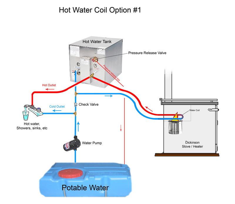
19 19 9. Optional Hot Water Coil Installation A hot water coil can be added to also enjoy water heating from your Dickinson diesel stove. You can either order your heater with one already installed in the stove or you can install the coil later yourself. Hot water coils are made of 5/8 OD stainless steel tubing and are available in a 1 turn coil for all model stoves to heat approx gallons of water. Hot water coils are also available in 2 turn coils all models except the Bristol to heat approx gallons of water. To plumb the hot water to the stove, ½ copper tubing should be used with the compression fittings provided. The coil in a stove can be used to heat the water in your existing hot water supply tank. If the tank is mounted above the lower coil, the water will circulate on its own from the tank into the hot coils and rise back into the tank by convection. If not, the water will need to be circulated by a low volume water pump. The temperature of the water will change depending on the speed of which it s circulating and the operating settings on the stove. It takes approx btu s to raise 10 gallons of water to 30 degrees in 1 hour. Most of the btu s that the stove produces is dissipated as radiant heat and is expelled through the chimney. Therefore, only a general guideline as to water heater capability can be set. WARNING: A pressure relief valve must be present or dangerous pressure buildup will occur. *See diagrams on pg. 21 It is best to order the stove with the coil already installed but follow these instructions for replacing or installing a new coil. 1. Remove the 6 screws that hold the top down onto the stove and remove the cast iron top. Save the 6 fastener clips that receive the screws underneath the stove top. Then plug the burner so debris won t clog your fuel lines. 2. Remove any old sealant away from the stove walls and underside of the cast iron top.
20 20 3. Punch 2 holes at 5/8 th in diameter in the back of the combustion chamber. Your stove may have punch-outs in the back wall of the stove for the coil. If so, remove them. Use a 5/8 drill bit and drill out the cement from the back of the stove where the coil holes are. 4. Remove the firebrick to get the coil in. Do not be too concerned with the appearance of your firebrick but if it is crumbled it s time for a new one. Install the coil so the ends of the coil stick 2 from the back of the stove. 5. Drill a hole and position the bracket that was included with the coil, to hold the coil in place with a 1/8 th drill bit. Use the #10 x 1 1/4" screw to screw down the 'L' shaped bracket. Clamp down the coil between the two bracket pieces. This bracket keeps the coil in place. It is important that the coil be installed so there is a constant rise in the tube as it goes to the back of the stove. This aids in the movement of the water or glycol. 6. Paste cement or hybond sealant around the coil ends as they exit the stove. If you are using cement then mix with water. It is not too important to get the consistency exact but oatmeal is a good consistency to aim for. Also, cement around the firebrick supports. The cement or sealant will need 24 hours to dry completely. 7. Use the left over cement or hybond sealant to repair any cracks or missing portions of the insoline cement liner as the combustion chamber needs to be air tight for the stove to work correctly. 8. Re-position the fasteners clips so they will receive the screws when screwing down the cast iron top to the stove walls. You will need 6 stainless or galvanized #10 ¾ flat head screws. 9. Apply a generous amount of hybond sealant to the top of the stove walls and over the fastener clips. 10. Re-place the cast iron top and screw down into the fasteners. Use the remaining hybond sealant to fill in any cracks between the top and the stove. The combustion chamber needs to be air tight for the stove to work correctly. *See diagrams on pg. 21
21 21
22 Operation The first time the oil-metering valve is turned on it will take 5-10 minutes for the fuel lines to fill and oil to appear in the bottom of the burner. Lighting Procedure 1. Turn on the fuel pump or open the gravity feed valve to allow fuel to flow into the oil metering valve on the stove. 2. Open the lid and twist the superheater so the bottom makes a good contact with the bottom of the burner. 3. Lift and turn the oil metering valve knob on to setting #5 for 2 minutes to accumulate 2 tablespoons of oil in the bottom of the burner pot. 4. Then turn the oil metering valve OFF. 5. Twist a piece of tissue, light it and throw it into the pool of oil in the burner pot. Use a poking tool to push the lit paper into the pool of oil. 6. Once the oil has ignited, replace the lid. 7. Turn the draft assist fan on to the medium speed (6 o clock) then turn it back down to the slowest speed (4 o clock). 8. After a few minutes, watch the flames grow above the top burner ring where they should burn at all times. 9. It will take approx minutes for the priming fuel to burn. Once the flames drop back down into the burner pot it s time to turn the oil metering valve back on. 10. Lift and turn the oil metering valve knob to setting #2.5 and turn the fan OFF and watch the flames grow back to above the top burner ring. 11. Wait 20 minutes for the heater and chimney pipe to warm up before you adjust the valve further. *NOTE: The flames must ALWAYS burn above the top burner ring regardless of the valve setting. ***DANGER: If the flames go out at any point at this stage, turn the valve off and wait 5-10 minutes for the burner to cool. Re-lighting warm diesel or a flooded burner can result in an explosion. *Do not use gasoline or any other flammable materials to light the burner. Do not operate this heater unattended.
 # 2 to # 3 4 to 5 o clock Medium # 3 to")
23 Approximate Valve & Fan Settings Heater Temperature Valve Setting Fan Knob Position Cold Start # 2 to # 3 Off Warm Low # 1 to # 2 Off Warm Low (cold or windy) # 2 to # 3 4 to 5 o clock Medium # 3 to # 4 5 to 6 o clock Medium (cold or windy) # 4 to # 5 6 to 7 o clock High # 5 7 o clock * Operating the fan can deliver too much air and cause the burner to run too lean (too much air in the fuel to air mixture). If you find that the flames start to burn below the top burner ring, turn the fan down slightly or increase the fuel slightly. * The fan has a low amperage motor and will need to have the speed control turned up to a faster speed to get the fan blade spinning, then turn it down to the appropriate setting. This also applies, should the fan blade rattle. * The best low speed setting is at the 4 to 5 o clock position on the speed control knob. The best medium setting is at the 5 to 6 o clock position and the best high setting is at the 6 to 7 o clock position. * When turning up the valve wait a minute and watch the flames react before adding air.
24 Operation Tips When operating on the lower temperature settings the burner needs less air. To reduce the air, adjust the barometric damper open wider, turn off the fan, and add more fuel even if you do not want the heat. It is better to make too much heat and dissipate it than to run the burner too lean with flames inside the burner pot as this will result in hard carbon build up and soot. The burner is designed to burn a certain amount of fuel on low and if less fuel is burned, it causes the flames to end up below the ring, inside the burner pot causing an unclean burn. Turning up the valve in small increments will help the draft to catch up with the fuel increases, keeping a good fuel to air mixture, which helps in reducing soot. When on medium to higher settings, the flames start to look orange with black tips, turn the fan on using the lowest fan speeds, increase air slowly until the flames start to turn yellow and more vibrant. If you turn the fan on too high the air will burn off all the fuel leaving the flames below the burner ring resulting in carbon soot. ***Remember, the key to burning this heater correctly is to find the right fuel to air mixture. When adjusting the fuel, you must adjust the air to find the correct balance so you have the cleanest burn. After the stove is well heated and cabin temperature is reaching comfortable temperature, the valve body and the fuel in it will start to warm up and the fuel will become thinner, flowing faster causing the heater to burn hotter. An adjustment will have to be made to turn down the fuel to a lower setting or add more air for a higher setting. Stove Damper The damper is controlled by the brass rod located to the right to the flue pipe. When the rod is up the damper is closed and when it is down the damper is open. When the damper is closed the heat is distributed more evenly around the oven and allows for more even cooking. When the damper is in the open position it allows for better draft and the flame will burn better. When lighting your stove the damper should always be in the open position.

25 25 Please visit our website and view Dickinson Marine s Operation Video

26 Flooding the Burner A vaporizing oil burner of this type can be flooded if care is not taken to prevent excess oil entering the burner when lighting. By following the lighting instructions flooding will be avoided. A flooded burner that is still burning should be turned off and the heater monitored until the oil has burned off. Use the combustion assist fan to add air to fully combust the excess fuel. Reasons that will flood your burner. Increasing the fuel supply too quickly without use of the combustion assist fan. Poor draft and/or ventilation. The suggested method to fix a flooded burner is to sacrifice a toilet paper roll as a perfectly fitted sponge and then dispose of the oil soaked roll. For this reason, always monitor the heater closely when lighting. DANGER: This oil must be removed from the pot before the heater is lit again or the stove will dangerously overheat. If the flame has extinguished, the oil metering will continue to deliver fuel to the burner causing it to accumulate fuel to a level of 5/8 from the bottom of the burner and no more for 6 burners (Bristol, Bering, Adriatic and Pacific). The 7 burners (Atlantic and Beaufort models) with a accumulate 1 of fuel from the bottom of the burner. Never relight this amount of fuel.

27 The Oil Metering Valve & Fuel Flow Safety Fuse A high temperature fuse is incorporated into the oil metering valve. The adjusting screw on the top of the knob of the oil metering valve is fitted with a fusible sleeve. This fuse will melt if the valve knob reaches a temperature of 165 degrees F. This will shut-off the flow of oil into the burner. Under normal conditions, the valve is at room temperature. If the high fire sleeve melts it indicates too much heat is by the valve compartment. Overheating of this kind is due to burning the heater too lean with the flames burning down in the burner pot and should be rectified before the heater overheats again. In case of the release of the high temperature fuse, remove the brass nut and do not move the adjusting screw. Apply heat from a lighter to re-solder the link back into its original position which was flat on the top. Once back in place the adjusting screw will not need re-adjusting. Make sure to now burn the stove correctly with ALL flames above the top of the burner. See the Operating Tips section of this Manual. Fuel Adjustment The height of the valve-adjusting knob will determine the quantity of oil exiting from the valve outlet. The height is determined by the length of the metering screw against the fuel ramp on the main casting of the valve. Remove the anti-vibration set screw (5/64 or 2.5mm Allen key) located in the center of the brass nut on top of the knob (turn counterclockwise). The adjusting screw may be (5/64 Allen) or a very small flat head. Adjust 1/8 turn at a time. After finishing the adjustments, return the set screw using needle nose pliers to hold the adjuster from turning when locking set screw in place
28 28 Fuel Flow Measurements If your heater is burning rich (making soot or smoking) or burning lean (flames not burning above the top burner ring), adjust the valve fuel flow as follows regardless of what type of fuel: 1) Unscrew the compression nut from the bottom of the valve with 2 wrenches and bend away the copper fuel line. Allow the oil to drip into a cup or container. 2) Lift and turn the valve knob to the #1 setting. Measure the quantity of oil dripping slowly from the fuel outlet. On Setting #1: All models 1 teaspoon in 60 seconds (4 c.c.'s per minute) 1.29 IMP Gal per day on low setting Atlantic 1 teaspoon in 53 seconds (5 c.c.'s per minute) 1.61 IMP Gal per day on low setting Beaufort 1 teaspoon in 45 seconds (6 c.c.'s per minute) 1.93 IMP Gal per day on low setting Fuel Variations It is unlikely that the fuel you are using is the same viscosity as the fuel used to calibrate the oil-metering valve. Diesel is one of the few fuels you can reliably get all around the world but the quality and viscosity of that fuel is variable. Fuel differs on a routine basis even though you buy the same oil from the same supplier. Factors influencing oil viscosity include: the temperature; the age and quality of the fuel; the regional differences due to local refineries; and the particular mix of certain brands of fuel. The oil metering valve is calibrated for #2 diesel, unless otherwise requested. Burning diesel #1 (stove oil) will allow 25% more fuel and burning kerosene will allow 50% more fuel to flow through the oil-metering valve. Because of this, it is important to burn the fuel for which the heater has been calibrated. Metering valves are available for diesel (D stamped on the side of the valve), kerosene (K) or stove oil (SO).
29 29 It is important to know that although you can re-calibrate your valve to each variation of fuel, you can also adjust the way you operate the stove to compensate for these variations. If the oil is thicker than usual, open the valve more or use less of the fan. If the fuel is thin, run the fan more to burn off the fuel to keep a clean burn. NOTE: Bio-Diesel is not recommended for use in Dickinson diesel stove and heaters due to the extreme viscosity changes due to temperature changes and the lack of consistency available throughout the different regions. Using Bio-Diesel in your stove/heater can result in but is not limited to clogged fuel lines and oil metering valves, inconsistent burn, lack of heat, carbon encrusted burn pot and rich sooty burn. Oil Metering Valve Operating Ranges
30 30 Oil Metering Valve Repair Kits The oil metering valves have 3 generations as the size of the inside components have changed over the years. Valves from the 2006 to present generation will have a C stamped on the side of the valve. Before 1994: No components available (must replace valve) : Repair Kit part# Present: Repair Kit part# C Includes: float, float pin, high temp screw, fuel screen, O ring, needle, seat, & washer. Oil Metering Valve Repair The repair kit has been packed with all the parts to rebuild your oil metering valve. The parts may differ in detail from what you have in your valve. This is due to changes and to the unavailability to the parts over the decades. 1. Disconnect the copper fuel lines from the valve inlet and outlet and overflow using 2 wrenches, then remove the valve from the mounting bracket, do not remove the bottom fitting or the overflow fitting from the valve. Unscrew the two retaining screws holding the valve top to the body. Note that the valve top and the valve knob are attached. 2. Remove the float from the float pin; remove the needle from the seat fitting. Using a 5/16ths socket, remove the seats fitting from the valve top casting; however leave the copper washer in. 3. Remove the fuel inlet fitting only and clean or replace the stainless screen behind the inlet fitting. Clean the threaded aperture in the top casting to remove any dirt or buildup. Perhaps use a pipe cleaner to clean the path from the inlet hole to the seat fitting aperture. 4. Remove and replace the viton o ring on the valve stem, and clean the stem groove. Clean out the stem guide in the bottom of the valve housing and the overflow tube.
31 31 5. Clean the inside of the valve housing castings, top and bottom. Replace oil inlet screen with new and replace the inlet fitting into the top casting (use teflon tape and do not over tighten). 6. In kit only, place the small adaptor in over the copper washer and place the new copper/brass washer over the adaptor, then screw in the new seat into the top casting until tight but not so tight as to damage the aluminum threads of the casting (35 inch pounds). 7. Place the new needle in the seat and slide the new float on so the flat bracket groove catches the neck of the needle. 8. Insert the float hinge pin and test the movement of the float up and down and that it moves the needle up and down in the fitting. (When held upsidedown, the bottom of the float should be parallel to the casting of the valve, in both directions). This very important to keep the float from binding on the stem guide as it moves up and down. If the float is not parallel to the casting, the float pin tabs on the float will need adjusting. Hold the float firmly and bend the tabs using needle nose pliers, being gentle to not break the float from the tabs (a small crack is acceptable). Bend both tabs down or both up to keep the float level parallel, being careful not to put pressure on the needle and seat when making the adjustments. Check the float for sitting perfectly straight as you may need to bend one tab up and the other tab down in order to achieve the bottom of the float straight in both directions. 9. Replace the top casting into the bottom casting so the metering stem slides in to the metering guide with oil inlet on the same side as the oil overflow. Replace the 2 top screws snugly, and move the control knob up and down while tightening the 2 screws. Once tight, the control knob should move up and down freely in any position. 10. Measure your fuel flow to the specifications on Pg. 27. Once you have adjusted the flow rate, check the overflow fuel line for oil drips. If the float is operating correctly and adjusted parallel to the casting, the oil level in the valve will be correct. The high fire screw inserted into the high temperature fuse can also be replaced or kept as a spare.

32 32 Oil Metering Valve Diagram
 There are two components in the 6 burner that must be correctly placed for the heater to operate properly.")

33 Burner Assembly The Bristol, Bering, Adriatic & Pacific model stoves has been equipped with a 6 Airflow burner and the Atlantic and Beaufort model stoves have a 7 Breeze burner. 6 Burner (Bristol, Bering, Adriatic & Pacific) There are two components in the 6 burner that must be correctly placed for the heater to operate properly. The burner ring must be placed at the top of the pot so the outside edge of the ring fits into the groove in the top of the pot. Ensure that the ring fits in evenly and snugly all the way around the pot and that all of the oval shaped slots are clearly visible. The second component is the superheater. The superheater is placed through the burner ring and will sit on the bottom of the burner with the round 2 disc sitting 2 up from the bottom of the burner. The bottom of the superheater should sit flat on the bottom of the burner to radiate heat to the fuel coming in through the center of the superheater washer. This will need to be kept clean to allow fuel to flow through it. The ring of the superheater will sit up above the burner ring where the flames are and radiate heat down to the vaporizing fuel. The 2 round disc sitting 2 above the bottom of the burner deflects the hot rising vapor up the sides of the burner pulling in the primary air needed to mix with the fuel.

34 34 7 Burner (Atlantic & Beaufort) There are three components in the 7 burner that must be correctly placed for the stove to operate properly. The stainless bottom ring must be placed on the three pegs that stick out from the burner wall. The second ring is the cast iron leg ring. It is placed on the stainless steel ring with the legs down. The last ring is the cast iron split rings. They are placed at the top of the burner with the two halves folded together to form a circle. It is important to install these components correctly and to inspect them periodically for warping or cracking.
35 Maintenance Fuel Maintenance Checklist (CHECK ONCE A YEAR) 1) Disconnect the fuel inlet line from the valve and place into a bucket. Turn on your pump or open your gravity feed valve to ensure there is a constant flow of fuel. This will indicate your fuel filter and fuel pump are operating correctly. 2) Remove the fuel inlet fitting from the valve and clean the screen behind. 3) Replace fuel inlet line to the fuel inlet fitting. Disconnect the fuel outlet line and place a cup or small container underneath the valve. 4) Turn the valve on to setting #1 and measure the fuel drip from the fuel outlet of the valve. It should measure 1 teaspoon per seconds. This will indicate that the valve is working correctly. 5) Before re-connecting the fuel line, put some paper towel inside the burner pot and blow into the fuel line so if any dirt is in there, it will blow into the burner onto the paper towel. 6) Re-connect the fuel line to the fuel outlet on the valve and wipe the inside of the burner clean with the paper towel. Cleaning the Burner Carbon accumulates in the burner over a period of time and it must be cleaned out or the air cannot get into the burner and the stove will not operate correctly. It is especially important to ensure the air holes are clear. If you are burning good quality fuel and the stove is burning efficiently above the top burner ring this cleaning procedure will only be required once a year. If there is rapid carbon build up in the burner pot, it indicates the stove is not being operated correctly or the need for a barometric damper adjustment. If you do not have a barometric you should install one to reduce the air in the burner that is causing the carbon build up. This must be rectified for satisfactory operation of the stove. 1) Open the lid and remove the burner ring and the superheater 2) Insert the reamer tool provided into the fuel inlet hole. This will prevent loose carbon from falling into the fuel inlet during cleaning. 3) With a wire brush, scrape any loose carbon from the sides of the burner.
Operating and Installation Instruction Manual
 Natural Draft Diesel Stove Operating and Installation Instruction Manual *KEEP THIS MANUAL FOR FUTURE REFERENCE* Sig200 & Sig250 Stove Models ** Please read from beginning to end before installing and
INSTALLATION AND OPERATING MANUAL. This manual MUST be read carefully and all requirements carried out to ensure satisfactory performance.
 INSTALLATION AND OPERATING MANUAL This manual MUST be read carefully and all requirements carried out to ensure satisfactory performance dickinson since 1932 Dickinson Marine (1997) Ltd 407-204 Cayer Street,
Pacific/Adriatic Diesel Cookstove Operator s Manual This manual must be read and the requirements carried out to ensure satisfactory performance.
 SINCE 1932 Dickinson Marine #407-204 Cayer St Coquitlam BC Canada V3K 5B1 www.dickinsonmarine.com info@dickinsonmarine.com T: 800 659 9768 F: 604 525 6417 Pacific/Adriatic Diesel Cookstove Operator s Manual
32,000 BTU INSTALLATION AND OPERATING MANUAL
 SINCE 1932 Dickinson Marine Products #407-204 Cayer St. Coquitlam B.C. Canada V3K 5B1 www.dickinsonmarine.com info@dickinsonmarine.com T: 800 659 9768 32,000 BTU INSTALLATION AND OPERATING MANUAL This
APPENDIX A LIGHT SOURCE
 APPENDIX A LIGHT SOURCE GASOLINE LANTERN One source of artificial light for the field kitchen is the gasoline lantern (NSN 6260-00-170-0430). It is a one-mantle lantern with a heat-resistant globe or globe
TITAN Fuel Tanks. INSTALLATION INSTRUCTIONS G e n e r a t i o n V
 TITAN pt. no.: 02 0000 0128 Important: Please read these instructions carefully and completely before starting the installation. TITAN Fuel Tanks INSTALLATION INSTRUCTIONS G e n e r a t i o n V Extended
Operator's Manual. Model: RY10MK-PRO MPN: RA-MLT Gallon Direct Fire Melter Kettle Burner Model with Adjustable Flame-Out Valve
 Operator's Manual Model: RY10MK-PRO MPN: RA-MLT-0009 10 Gallon Direct Fire Melter Kettle Burner Model with Adjustable Flame-Out Valve U.S. Patent No. 9,739,021 For Technical Support Please Visit www.rynoworx.com
SERVICE MANUAL V-SERIES HEAVY DUTY BROILERS, DOUBLE DECK AND RANGE MATCH MODELS - NOTICE - For a complete listing of models, see the MODELS section.
 SERVICE MANUAL V-SERIES HEAVY DUTY BROILERS, DOUBLE DECK AND RANGE MATCH MODELS For a complete listing of models, see the MODELS section. - NOTICE - This Manual is prepared for the use of trained Vulcan
INSTRUCTIONS FOR MVK-NQM PILOT KIT
 MVK-NQM IMPORTANT READ AND UNDERSTAND THESE INSTRUCTIONS BEFORE INSTALLING These instructions must be used as a supplement to the instructions supplied with your gas log set. Follow the Gas Log Set instructions
TUBULAR BURNER CONVERSION KIT AGCK-TBXX / AECK-UBXX
 TUBULAR BURNER CONVERSION KIT AGCK-TBXX / AECK-UBXX IMPORTANT - READ ALL INSTRUCTIONS BEFORE YOU BEGIN THE INSTRUCTIONS HEREIN SHOULD BE PERFORMED BY A QUALIFIED SERVICE TECHNICIAN. THE GRILL MUST BE COMPLETELY
Gas Conversion Kits and Instructions
 Gas Conversion Kits and Instructions INSTALLATION FORM RGM 432/433-GC (Version D.1) Obsoletes Form RGM 432/433-GC (Version D) APPLIES TO: Model FT and Model SFT All gas conversion must be done by a qualified
Product instruction manual Ream Cutting Systems RE3943, RE3946, RE3947, RE3971, RE3952E
 Product instruction manual Ream Cutting Systems RE3943, RE3946, RE3947, RE3971, RE3952E The Trimfast Ream Cutters are reliable, high performance cutters that will give you the results you need quickly
Model 205 Fireview Maintenance Kit
 Model 205 Fireview Maintenance Kit Please read all of the instructions before you begin the procedure. Confirm that you have all the necessary tools and parts required. Allow about one hour to complete
For converting 72 PKN for use with (LP) propane gas.
 propane gas.") IMPORTANT READ AND UNDERSTAND THESE INSTRUCTIONS BEFORE INSTALLING These instructions must be used as a supplement to the instructions supplied with your gas log set. Follow the Gas Log Set instructions
IMPORTANT READ AND UNDERSTAND THESE INSTRUCTIONS BEFORE INSTALLING These instructions must be used as a supplement to the instructions supplied with your gas log set. Follow the Gas Log Set instructions
INFRARED BURNER KIT INSTRUCTIONS
 6 4 3 2 INFRARED BURNER KIT INSTRUCTIONS 1 Model # 3049 (A790, A660, & A530) Model # 3051 (A540, & A430) Included parts 5 NOTE: This unit has been retrofi tted with an infrared burner. PARTS INCLUDED 1.
Assembly/Installation/Use Instructions:
 IMPORTANT We highly recommend that our products be installed and serviced by professionals who are certified in the U.S. by NFI (National Fireplace Institute) or in Canada by WETT (Wood Energy Technical
Genesis. Side Burner Accessory Installation. Step 3. Step 1. Step 2. For use with Genesis Gas Barbecues Only
 Genesis Side Burner Accessory Installation For use with Genesis Gas Barbecues Only Step 1 WARNING: All gas controls and supply valves should be in the OFF position. You will need: Side burner assembly
Getting Started Guide
 Getting Started Guide Assembly Instructions User Guide Table Top Maintenance Warranty Information (800) 445-4559 www.designingfire.com Fax: 651-305-6347 @designingfire.com #253915-2528907 Installers: Please
TCWS54 SEE THRU DIAMOND BURNER INSTALLATION KIT INSTRUCTIONS
 INSTALLER: Leave this manual with the appliance. CONSUMER: Retain this manual for future reference. These instructions are supplementary to the Installation and Operating Instructions supplied with the
FORCE 10 MARINE BARBEQUES
 FORCE 10 MARINE BARBEQUES PROPANE MODELS Model 3500 % Large Propane Model 3550 % Small Propane OWNER S MANUAL AND WARRANTY FORCE 10 MARINE LTD. 23080 Hamilton Road, Richmond, B.C. Canada V6V 1C9 Telephone
TCWS.38NG03.C BLACK DIAMOND BURNER KIT INSTRUCTIONS
 IMPORTANT: THESE INSTRUCTIONS ARE TO REMAIN WITH THE HOMEOWNER These instructions are supplementary to the Installation and Operating Instructions supplied with the fireplace and should be kept together.
SPK3E - Manual EASY Control
 SPK3E - Manual EASY Control General Assembly, Installation, and Operation Instructions for use with Natural Gas Burners; F, FX, CS, CXF, TNA or Propane Gas Burners: FA, FAX, CA, CXFA, TNA/LP LISTED BY
Thermostatic Griddle Field Service Kit Instructions
 Thermostatic Griddle Field Service Kit Instructions The following document provides instructions on how to install a Garland Thermostatic Griddle Field Kit and is applicable to each 2 section of a Garland
TECHNICAL SUPPORT HOT LINE HOURS: 7:30-3:30
 TECHNICAL SUPPORT HOT LINE 1-800-526-0725 HOURS: 7:30-3:30 TO: Service Providers BULLETIN No: 0102-1 FROM: SUBJECT: BOB VAN WYCK Technical Support Manager Burner Pilot Tube Replacement DATE: Feb 1, 2001
How to use a multi fuel stove
 How to use a multi fuel stove Important!! When lighting the stove for the first time only a small fire should be lit. Too hot a fire will result in the paint emitting smoke - not necessarily bad but unpleasant.
EB300. Ethanol Burner. User s Manual Installation Instructions
 EB300 Ethanol Burner User s Manual Installation Instructions EB300 Burner Burner Lid User s Manual What s in the box: 1pc 1pc 1pc Installation Instructions EB300 - User s Manual The Ignis Ethanol Burner
r e - p a r t s. c o m
 Owner s Manual SPK3E - Manual EASY Control General Assembly, Installation, and Operation Instructions for use with Natural Gas Burners; F, FX, CS, CXF, TNA or Propane Gas Burners: FA, FAX, CA, CXFA, TNA/LP
Installation and Maintenance Manual
 Freestanding Gas Stove MODEL: PGS2005 GPEBB20R GPEBW20R Installation and Maintenance Manual Warning Maintenance products should be carried out by professional and technical personnel with relevant qualification,
Corn Flame Energy Corn Stove Model 5000
 Corn Flame Energy Corn Stove Model 5000 Installation and Operation Guide Read thoroughly before starting installation Save this manual for future reference SAFETY NOTICE If this stove is not properly installed,
ASSEMBLY GUIDE. Customer Service: INCH² 2-BURNER & 864 INCH² 2-BURNER
 ASSEMBLY GUIDE 688 INCH² 2-BURNER & 864 INCH² 2-BURNER DANGER If you smell gas: 1. Shut off gas to the appliance. 2. Extinguish any open flames. 3. Open lid. 4. If odor continues, keep away from the appliance
ASSEMBLY GUIDE. Customer Service: INCH² 3-BURNER & 545 INCH² 3-BURNER
 ASSEMBLY GUIDE 455 INCH² 3-BURNER & 545 INCH² 3-BURNER DANGER If you smell gas: 1. Shut off gas to the appliance. 2. Extinguish any open flames. 3. Open lid. 4. If odor continues, keep away from the appliance
Manufactured in New Zealand Metal Fab Industries Ltd PO Box Greenmount Auckland
 Manufactured in New Zealand Metal Fab Industries Ltd PO Box 58-473 Greenmount Auckland Www.metalfab.co.nz LOGAIRE STAINLESS STEEL BBQ 2,3 & 4 Burner Models IMPORTANT Please read all instructions before
Lit Table Top Firepit Bio-Ethanol Fireplace. User Manual. Model: GF301650
 Lit Table Top Firepit Bio-Ethanol Fireplace User Manual Model: GF301650 1 Moda Flame Lit Table Top Firepit Bio-Ethanol Fireplace Included in delivery (Parts List): A. Fireplace body 1pc B. Glass 1pc C.
MODEL DCC DOUBLE WALL CHIMNEY CONNECTOR
 Installation & Maintenance LISTED Tested to *UL 103HT & ULC-S641 Instructions MODEL DCC DOUBLE WALL CHIMNEY CONNECTOR A MAJOR CAUSE OF CHIMNEY RELATED FIRES IS FAILURE TO MAINTAIN REQUIRED CLEARANCES (AIR
Installation Guide: Round Trampoline
 Trampolines & trampoline parts designed to survive in the harsh Oz climate. www.oztrampolines.com.au Installation Guide: Round Trampoline Safety Tips Here at Oz Trampolines we are passionate about your
Please read this manual before installation and use. We wish you many years of pleasure and warmth.
 Thank you for purchasing this product. This multi fuel burning stove is compliant with the EN13240 Please read this manual before installation and use. We wish you many years of pleasure and warmth. Manufactured
MODEL DCC DOUBLE WALL CHIMNEY CONNECTOR
 Installation & Maintenance LISTED Tested to *UL 103HT & ULC-S641 Instructions MODEL DCC DOUBLE WALL CHIMNEY CONNECTOR A MAJOR CAUSE OF CHIMNEY RELATED FIRES IS FAILURE TO MAINTAIN REQUIRED CLEARANCES (AIR
SMART BIO-ETHANOL ELECTRONIC BURNER
 SMART BIO-ETHANOL ELECTRONIC BURNER User s Manual What s in the box: Smart Burner Remote Control AC Adapter Filling Hose User s Manual 1pc 1pc 1pc 1pc 1pc Preparations Remove all packaging materials prior
Compact Stainless Spit Roast
 Compact Stainless Spit Roast Instructions As soon as you get the machine to your destination please start it up and make sure it works following the Instructions below. This is just in case something has
Installation and User s Manual 12 x 10 MOTORIZED AWNING
 12 x 10 MOTORIZED AWNING Installation and User s Manual 12 x 10 MOTORIZED AWNING 088-1763-0 Stop Please read and understand this manual before any assembly or use of this product. Before beginning assembly
Instructions for Converting Range to Operate on Liquefied Petroleum Gas
 INSTALLATION AND SERVICES MUST BE PERFORMED BY A QUALIFIED INSTALLER IMPORTANT: SAVE INSTRUCTION MANUAL FOR THE LOCAL INSPECTOR S USE. READ AND SAVE THESE INSTRUCTIONS FOR FUTURE REFERENCE This conversion
Studio stove, Studio oven and Oh-Ah
 Studio stove, Studio oven and Oh-Ah Maintenance and Operating Instructions Visit www.warmington.co.nz for specs, DWG s and PDF uploads of fires Fire, flue system and instructions to comply with AS/NZS
INFRARED BURNER KIT INSTRUCTIONS
 3 INFRARED BURNER KIT INSTRUCTIONS (HOT SURFACE IGNITION) 5 1 4 NOTE: This unit has been retrofi tted with an infrared burner. Model # 3050 # 3060 Included parts 2 6* PARTS INCLUDED 1. Infrared burner
RMC1E - Variable Flame Height EASY Control
 Owner s Manual RMC1E - Variable Flame Height EASY Control General Assembly, Installation, and Operation Instructions for use with Natural Gas Burners; F, FX, CS, CXF, TNA or Propane Gas Burners: FA, FAX,
HARVIA IRON STOVE Instructions for installation and use
 HARVIA IRON STOVE EN Instructions for installation and use Harvia 10 08012014VTT Congratulations on a good choice of fireplace and thank you for your confidence in Harvia s products. Read these instructions
TC36 SEE-THRU LODGEWOOD BURNER AND PANEL KIT INSTRUCTIONS
 IMPORTANT: THESE INSTRUCTIONS ARE TO REMAIN WITH THE HOMEOWNER These instructions are supplementary to the Installation and Operating Instructions supplied with the fi replace and should be kept together.
Colonial and Grand Colonial Fire Pit Tables. Installation Instructions for
 Colonial and Grand Colonial Fire Pit Tables Installation Instructions for Colonial-48-M-K, Col-48-MNB-K, Grand-Colonial-48-K, CM-48-DIN-K, MNB-48-DIN-K, GC-48-DIN-K, CM-48-PUB-K, MNB-48-PUB-K, GC-48-PUB-K
Therme storage water heater. Table of contents. Symbols used. Symbols used Symbol indicates a possible hazard. Installation instructions
 Therme storage water heater Table of contents Symbols used... 8 Installation instructions Water supply... 9 Choice of location... 9 Installation of the Therme... 9 Fitting the draining and venting valve...
INSTALLATION & OPERATING INSTRUCTIONS FOR. FIREPLACE GAS LOGS Model Numbers: MO18NG, MO24NG, SH18NG, SH24NG, CSO30NG
 INSTALLATION & OPERATING INSTRUCTIONS FOR FIREPLACE GAS LOGS Model Numbers: MO18NG, MO24NG, SH18NG, SH24NG, CSO30NG Applicable for use with all styles and sizes of Dual Burner Natural Gas Log Sets. Note:
INSTALLATION AND OPERATIONS GUIDE FOR GRAND CANYON GAS LOG FIRE PIT SERIES ONLY
 INSTALLATION AND OPERATIONS GUIDE FOR GRAND CANYON GAS LOG FIRE PIT SERIES ONLY Installation and service must be provided by a qualified installer, service agency or gas supplier Grand Canyon Gas Logs,
GoBidet Bidet Attachment
 GoBidet Bidet Attachment 151 Ruths Place #5 Sequim, WA 98382 Tel 1-800-681-0753 Fax +1 360-681-4029 www.go-bidet.com MODEL #2003C In this box: 1 User Manual 1 GoBidet Unit w/ mounting bracket, nut, rubber
TC36 CHALET BURNER KIT INSTALLATION INSTRUCTIONS
 INSTALLER: Leave this manual with the appliance. CONSUMER: Retain this manual for future reference. These instructions are supplementary to the Installation and Operating Instructions supplied with the
Eaton ET Hydraulic Hose Saw INSTRUCTION MANUAL
 Eaton ET9100-07-110 Hydraulic Saw INSTRUCTION MANUAL INSTRUCTION MANUAL Eaton ET9100-07-110 Hydraulic Saw Table of Contents Introduction... 3 Old Method... 3 New Eaton Method... 3 Operation... 4 Operation
TWO BURNER STAINLESS STEEL PROPANE STOVE
 ROTATE TO LIGHT 842-A250-0_SSCmpStove.qxd 11/26/03 2:59 PM Page 1 OWNER S MANUAL FAILURE TO FOLLOW ALL S AND INSTRUCTIONS IN THIS MANUAL COULD LEAD TO PERSONAL INJURY, INCLUDING DEATH. RETAIN THIS MANUAL
CONVERSION INSTRUCTIONS
 CONVERSION INSTRUCTIONS Natural Gas to Propane Gas Conversion Kit For Thermador Professional Cooktops and Ranges Model STARLPKIT Part No. 35-00-682 Contains 7mm Hex Main Orifices This kit is used to convert
Installation Guide. LPKPDR - Universal LP Conversion Kit for Professional & Designer Ranges/Rangetops. Viking Range, LLC.
 Installation Guide Viking Range, LLC 111 Front Street Greenwood, Mississippi 38930 USA (662) 455-1200 For product information, call 1-888-845-4641 LPKPDR - Universal LP Conversion Kit for Professional
Inspecting your combustor
 Inspecting your combustor Ash, a fluffy light grey powder, and soot, a darker granular material, accumulate on the combustor surfaces in normal use. Ashes accumulate both as a result of the smoke being
TC36 CHALET II BURNER KIT INSTALLATION INSTRUCTIONS
 INSTALLER: Leave this manual with the appliance. CONSUMER: Retain this manual for future reference. These instructions are supplementary to the Installation and Operating Instructions supplied with the
Toyostove Error Code EE 2 (EE 6)
") Toyostove Error Code EE 2 (EE 6) WARNING Rural Energy Enterprises, Inc. does not accept liability for the improper use of this information. Installation, service, and maintenance of heating equipment should
Toyostove Error Code EE 2 (EE 6) WARNING Rural Energy Enterprises, Inc. does not accept liability for the improper use of this information. Installation, service, and maintenance of heating equipment should
Instructions for Converting Range to Operate on Liquefied Petroleum Gas
 INSTALLATION AND SERVICES MUST BE PERFORMED BY A QUALIFIED INSTALLER IMPORTANT: SAVE INSTRUCTION MANUAL FOR THE LOCAL INSPECTOR S USE. READ AND SAVE THESE INSTRUCTIONS FOR FUTURE REFERENCE This conversion
300 Model 870 Four Wheel Hose Cart Owner s Manual
 300 Model 870 Four Wheel Hose Cart Owner s Manual IMPORTANT: READ THE OWNER S MANUAL BEFORE ASSEMBLING TOOLS REQUIRED: TWO ADJUSTABLE WRENCHES; HAND PUMP Estimated assembly time: 30 minutes PARTS LIST
WIDESPREAD LAVATORY MODELS WITH HI-ARC SPOUT
 5951, 5961, 5981, 5983, 5993 SERIES MT122B INSTALLATION INSTRUCTIONS THESE INSTRUCTIONS MUST BE LEFT WITH HOMEOWNER WIDESPREAD LAVATORY MODELS WITH HI-ARC TRADITIONAL CROSS NOTE: Handle Inserts are not
280 Propane Barbecue Assembly Manual
 280 Propane Barbecue Assembly Manual 85-3001-8 (G20718) Propane 1 Year limited Warranty Read and save manual for future reference. Assemble your grill immediately. Missing or damaged parts claims must
Maintenance 45 Serie CAUTION. Before resetting your electronic card that displays an error code.
 29-10-2013 CAUTION Before resetting your electronic card that displays an error code. Error Code H Service the stove COMPLETELY as described in this manual. Check the chimney pipe. Error Code O Service
OIL BURNING STOVE EVEREST
 OWNER`S MANUAL OIL BURNING STOVE EVEREST Vérified and tested following CAN/CSA B140.3 et UL 896 standards by: Intertek Testing Services Manufactured by: 1700 Léon-Harmel Québec, (Québec) G1N 4R9 www.drolet.ca
INSTALLATION/OWNERS MANUAL for. Kodiak HAND FIRED GRAVITY FED COAL STOVE Columbia Blvd. Bloomsburg PA Fuel: Nut or Pea Coal
 INSTALLATION/OWNERS MANUAL for Kodiak HAND FIRED GRAVITY FED COAL STOVE 3162 Columbia Blvd. Bloomsburg PA 17815 Fuel: Nut or Pea Coal Caution Fossil fuel burning can create lethal doses of carbon monoxide
Tuf-Lite and Tuf-Lite II Fans 6000M Series Hub
 Tuf-Lite and Tuf-Lite II Fans 6000M Series Hub INSTALLATION MANUAL Adjustable Pitch Fan Assembly 32.8 or 10 Meter Diameter Hudson Tuf-Lite and Tuf-Lite II fan blades Hudson Tuf-Lite (black) fan blades
Gas Go Anywhere /23/01
 Gas Go Anywhere 55014 02/23/01 FOR OUTDOOR USE ONLY This grill does not include an LP fuel tank. Check Package Contents You should have received the parts listed below. While we give much attention to
TC30 HEARTWOOD BURNER INSTALLATION INSTRUCTIONS
 INSTALLER: Leave this manual with the appliance. CONSUMER: Retain this manual for future reference. These instructions are supplementary to the Installation and Operating Instructions supplied with the
For Outdoor Use Only!
 ITEM NAME: Red Ember Bronze Crossweave Firebowl Fire Pit with Free Cover and Fire Tool with Optional Grill Grate SKU: ALZ109 For Outdoor Use Only! 1. Improper installation, adjustment, alteration, service
ETHANOL FIREPLACES Certified as per ULC/ORD C UL Subject
 VOLCAN B12 Trident Laguna Vesuve ETHANOL FIREPLACES Certified as per ULC/ORD C627.1-2008 UL Subject 1370-2010 Fogo Kilauea Revised May 26, 2011 Taal Designed especially for fireplace hearth 490, rue de
TC30 BLACK DIAMOND BURNER KIT INSTRUCTIONS
 IMPORTANT: THESE INSTRUCTIONS ARE TO REMAIN WITH THE HOMEOWNER These instructions are supplementary to the Installation and Operating Instructions supplied with the fi replace and should be kept together.
INSTALLATION INSTRUCTIONS TOWNSEND
 INSTALLATION INSTRUCTIONS TOWNSEND.00 DECK MOUNT BATH FILLER.0 Thank you for selecting American Standard... the benchmark of fine quality for over 00 years. To ensure that your installation proceeds smoothly-please
INSTALLATION AND OPERATIONS GUIDE FOR GRAND CANYON GAS JUMBO/JUMBO SLIMLINE LOG SYSTEMS
 Burner Systems: JUMBOSLIMBRNR-24 JUMBOSLIMBRNR-30 JUMBOBRNR-36 / JUMBOSLIMBRNR-36 JUMBOBRNR-42 / JUMBOSLIMBRNR-42 JUMBOBRNR-48 / JUMBOSLIMBRNR-48 JUMBOBRNR-60 / JUMBOSLIMBRNR-60 INSTALLATION AND OPERATIONS
Installation and Operating. Instructions. Multifuel Stove. Salamander. Model Lighting a solid fuel fire. 6.5 De-ashing the stove
 Installation and Operating Instructions Salamander Model 0901 Multifuel Stove Section Contents Page 1 Important information about installing and 3 using the Salamander stove 2 Unpacking the Salamander
Voice Mail: (815) Fax: (815) OWNERS MANUAL
 Fax: (815) OWNERS MANUAL") www.countryhomescampers.com Email: info@countryhomescampers.com Voice Mail: (815) 346 3337 Fax: (815) 346 3337 OWNERS MANUAL Introduction: Your Country Homes Camper has been engineered and built with a
www.countryhomescampers.com Email: info@countryhomescampers.com Voice Mail: (815) 346 3337 Fax: (815) 346 3337 OWNERS MANUAL Introduction: Your Country Homes Camper has been engineered and built with a
Style # Laguna Propane Tank Cover Owner s Manual
 Style # 26100117 Laguna Propane Tank Cover Owner s Manual Warning: For outdoor use only DO NOT use for cooking DO NOT use under any overhead enclosure Manufactured as Model # 6561 in China for: Restoration
Mazdaspeed6 Stage 1 Location 2 OCC Kit Install guide
 1 Mazdaspeed6 Stage 1 Location 2 OCC Kit Install guide WARNING: By installing this Product, you understand that: The buyer/user assumes all risk as to quality, performance and use of these products and
TC42 TRANQUILITY BURNER KIT INSTRUCTIONS
 IMPORTANT: THESE INSTRUCTIONS ARE TO REMAIN WITH THE HOMEOWNER These instructions are supplementary to the Installation and Operating Instructions supplied with the fi replace and should be kept together.
Professional Series Galley Range
 Professional Series Galley Range OWNER S MANUAL Read all instructions and warnings before operating. Force 10 Manufacturing Corporation Unit A 19169 21 st Ave Surrey, BC V3S 3M3 Tel: 604.536.0379 Fax:
Tuf-Lite III Fans 4000KW Series Hub
 Tuf-Lite III Fans 4000KW Series Hub INSTALLATION MANUAL Hudson Tuf-Lite III fan blades Adjustable Pitch Fan Assembly 11 through 20 Diameter Hudson Tuf-Lite III fan blades are of single piece fiberglass
Installation, Operation, & Safety Handbook
 Installation, Operation, & Safety Handbook Model 1500 Model 2500 Obadiah's Wood Stoves 1660 Whalebone Dr. Kalispell, MT 59901 www.woodstoves.net 800-968-8604 Model 2500 and 1500 Freestanding Stove or Fireplace
Burner Plumbing on the Appalachian Center for Craft Crossdraft Soda Kiln
 Tennessee Tech University Appalachian Center for Craft Clay Studio Vince Pitelka, 2014 Burner Plumbing on the Appalachian Center for Craft Crossdraft Soda Kiln This kiln is 20 cubic feet interior space,
Afton Bay Operation & Maintenance Manual
 Afton Bay Operation & Maintenance Manual Table of Contents ST. CROIX FEATURES...2 INSTALLATION... 3 PREVENTING CHIMNEY FIRES...3 SATISFACTORY PERFORMANCE... 3 APPROVED FUELS...3 Pellets, Cherry Pits &
Installation instruction
 Installation instruction Ci51 116 FACTS Technical specifications Model i51 Log box (option) Output 6-11 kw Nominal output 8 kw Efficiency 80 % Weight (kg) 215 50 Powerstone (option): + 100 kg Width (mm)
Contents. Awnings USA - Full Protective Hood Manual Instructions ft 11" - 11ft 6" Awnings
 Awnings USA - Full Protective Hood Manual Instructions Contents Warning We recommend that two or more people are required to lift the awning into place. 4ft 11" - 11ft 6" Awnings 8 x Expansion bolts **
Installation Guide. Single-Control Kitchen Sink Faucets
 Installation Guide Single-Control Kitchen Sink Faucets K-6352 K-6353 M product numbers are for Mexico (i.e. K-12345M) Los números de productos seguidos de M corresponden a México (Ej. K-12345M) Français,
INSTRUCTION MANUAL ALEKO RETRACTABLE AWNING
 INSTRUCTION MANUAL for ALEKO RETRACTABLE AWNING www.alekoproducts.com FAILURE TO FOLLOW THESE INSTRUCTIONS MAY RESULT IN PERSONAL INJURY! 1 Important Safety Precautions WARNING NOTE: FOR PERSONAL SAFETY,
t420 Barbecue Assembly Manual
 t20 Barbecue Assembly Manual 85-300-2 (G510) Propane 85-3005-0 (G5105) Natural Gas 1 Year limited Warranty Read and save manual for future reference. If pre-assembled, leave this manual with unit for consumer
Blue Series Hot Melt Hose with RediFlext II Hanger System
 Instruction Sheet P/N 1124594_01 Blue Series Hot Melt Hose with RediFlext II Hanger System Safety WARNING! Allow only personnel with appropriate training and experience to operate or service the equipment.
Instructional Booklet
 Instructional Booklet 936-894-3292 Thank you for choosing The Bathmaster! You are on your way to creating an unmatched bathing experience both for you and the lucky animal. The Bathmaster is designed to
For Outdoor Use Only!
 ITEM NAME: Red Ember 4 ft. Smokestack Rubbed Bronze Fireplace with Cover SKU: ALZ655-1 For Outdoor Use Only! 1. Improper installation, adjustment, alteration, service or maintenance can cause injury or
Kuma Stoves Rathdrum, ID. USA
 Kuma Stoves Rathdrum, ID. USA MODEL: OIL CLASSIC (OC-7, OC-8, OC-10) Fuel-oil stove Report # 123-S-01-2 Tested and listed by Omni Test Laboratories User Manual for: -Installation -Operation -Servicing
JARVIS. Model 70 Airsnip Air Powered Scissors
 Air Powered Scissors EQUIPMENT SELECTION... Ordering No. Airsnip Model 70... 4019009 Air Filter/Regulator/Lubricator.. 3022003 Balancer... 1350084 Power--Pak (250 PSI)... 4026016 TABLE OF CONTENTS... Page
Brooks Fire Pit Table. Installation Instructions for Brooks Fire Pit Table BRK-1224
 Brooks Fire Pit Table Installation Instructions for Brooks Fire Pit Table BRK-1224 1 IMPORTANT Contents Please consult your Crystal Fire instruction manual for detailed instructions Required and important
300 ft. 5/8 Hose wagon
 300 ft. 5/8 Hose wagon Model 95956 Assembly And Operation Instructions Due to continuing improvements, actual product may differ slightly from the product described herein. (Garden hose is not included).
S405 Barbecue Assembly Manual
 S405 arbecue ssembly Manual 85-02-6 (G4705) Propane Year limited Warranty Read and save manual for future reference. If pre-assembled, leave this manual with unit for consumer s future reference. For product
INSTRUCTION MANUAL HYDM140
 INSTRUCTION MANUAL HYDM140 INSTRUCTION MANUAL Clean-Cuts HYDM140 Hydraulic Hose Saw Table of Contents Introduction... 3 Old Method... 3 New Clean-Cuts Method... 3 Operation... 4 Operation Procedure...
VALORE SEVEN. Serial Number. Pacific) Version No.:V
 Version No.:V") VALORE SEVEN Version No.:V.206222 Serial Number Pacific) 7 9 8 " 5 8 " " 7 2 8 " 26 2 " 7 8 " 9" 2 8 " 2 8 " (H) 26.9" x (W) 8.26" x (D) 8.85" Hand shower hose: 59.05" Weight: Net: 0 lbs /Gross: 2 lbs
VALORE SEVEN Version No.:V.206222 Serial Number Pacific) 7 9 8 " 5 8 " " 7 2 8 " 26 2 " 7 8 " 9" 2 8 " 2 8 " (H) 26.9" x (W) 8.26" x (D) 8.85" Hand shower hose: 59.05" Weight: Net: 0 lbs /Gross: 2 lbs
Cleaning Fireside Franklin Pilot Orifice
 Cleaning Fireside Franklin Pilot Orifice Please read all the instructions before beginning the procedure. Confirm that you have all the necessary tools and materials. If you have any questions technical