GENERATION III COULTER SET-UP & PARTS MANUAL
|
|
|
- Barnard Norman
- 6 years ago
- Views:
Transcription
 Website: www.yetterco.")
1 GENERATION III COULTER MODEL 2995 SET-UP & PARTS MANUAL _REV_D 07/13 YETTER MANUFACTURING CO. FOUNDED 1930 Colchester, IL Toll free: 800/ / (Fax) Website:
2 FOREWORD You ve just joined an exclusive but rapidly growing club. For our part, we want to welcome you to the group and thank you for buying a Yetter product. We hope your new Yetter products will help you achieve both goals-increase your productivity and increase your efficiency so that you may generate more profit. This operator s manual has been designed into four major sections: Foreword, Safety Precautions, Installation Instructions and Parts Breakdown. This SAFETY ALERT SYMBOL indicates important safety messages in the manual. When you see this symbol, be alert to the possibility of PERSONAL INJURY and carefully read the message that follows. The word NOTE is used to convey information that is out of context with the manual text. It contains special information such as specifications, techniques and reference information of a supplementary nature. The word IMPORTANT is used in the text when immediate damage will occur to the machine due to improper technique or operation. Important will apply to the same information as specified by note only of an immediate and urgent nature. It is the responsibility of the user to read the operator s manual and comply with the safe and correct operating procedure and to lubricate and maintain the product according to the maintenance schedule in the operator s manual. The user is responsible for inspecting his machine and for having parts repaired or replaced when continued use of the product would cause damage or excessive wear to the other parts. It is the user s responsibility to deliver his machine to the Yetter dealer who sold him the product for service or replacement of defective parts, which are covered by the warranty policy. If you are unable to understand or follow the instructions provided in this publication, consult your local Yetter dealer or contact: YETTER MANUFACTURING CO. 309/ / / (FAX) Website: info@yetterco.com WARRANTY Yetter Manufacturing warrants all products manufactured and sold by it against defects in material. This warranty being expressly limited to replacement at the factory of such parts or products as shall appear to be defective after inspection. This warranty does not obligate the Company to bear cost of labor in replacement of parts. It is the policy of the Company to make improvements without incurring obligations to add them to any unit already sold. No warranty is made or authorized to be made, other than herein set forth. This warranty is in effect for one year after purchase. Dealer Yetter Manufacturing warrants its own products only and cannot be responsible for damages to equipment on which mounted. 2
3 SAFETY A brief description of signal words that may be used in this manual: CAUTION: practices. WARNING: DANGER: Used as a general reminder of good safety practices or to direct attention to unsafe Denotes a specific potential hazard. Denotes the most serious specific potential hazard. SAFETY PRECAUTIONS You can make your farm a safer place to live and work if you observe the safety precautions given. Study these precautions carefully and insist that they be followed by those working with you and for you. Finally, remember this: an accident is usually caused by someone s carelessness, neglect, or oversight. WARNING Never clean, lubricate or adjust a machine that is in motion. Always lower or block the implement before performing service. If machine must be serviced in the raised position, jack or block it up to prevent it from accidentally falling and injuring someone. Do not allow riders on the tractor or implement. Use speeds and caution dictated by the terrain being traversed. Do not operate on any slope steep enough to cause tipping or loss of control. Be sure all personnel are clear of the immediate area before operating. Read and understand the operator s manual and require all other persons who will operate the equipment to do the same. Be familiar with all tractor and implement controls and be prepared to stop engine and implements quickly in an emergency. CAUTION Consult your implement and tractor operator s manual for correct and safe operating practices. Beware of towed implement width and allow safe clearance. FAILURE TO HEED MAY RESULT IN PERSONAL INJURY OR DEATH. 3
4 YETTER MODEL 2995 GENERATION III COULTER FERTILIZER COULTER ASSEMBLY, RH L FERTILIZER COULTER ASSEMBLY, LH COULTER ASSEMBLY, RH L COULTER ASSEMBLY, LH CLAMPS (DIMENSIONS ARE INCHES HORIZONTAL X VERTICAL) Part No. Description Clamp Kit, 3 X 6 Bar Clamp Kit, 2 Sq. Bar Clamp Kit, 2 1/2 Sq. Bar Clamp Kit, 2 x 6 Bar Clamp Kit, 4 x 4 Bar Clamp Kit, 5 x 7 Bar Clamp Kit, 7 x 7 Bar Clamp Kit, 3 Dmd Bar Clamp Kit, 3 1/2 Dmd Bar Clamp Kit, 3 x 7 Bar Clamp Kit, 2 1/2 Sq., 1/2 Spacer Clamp Kit, 3 Sq. Bar Clamp Kit, 2 1/4,2 1/2 Dmd Bar Clamp Kit, 3 x 4 Bar Clamp Kit, 4 x 6 Bar Clamp Kit, 6 x 4 Bar Clamp Kit, 7 x 5 Bar Clamp Kit, 7 x 4 Bar Clamp Kit, 4 x 10 Special Clamp Kit, 4 x 7 Bar Clamp, Air Seeder Clamp Kit, 5 x 5 Bar SHANKS (TOTAL LENGTH OF SHANK IN INCHES) Part No. Description Shank, 12 5/8 Long, 3 Offset Shank, 27 Long, 3 Offset Shank, 12 5/ Shank, Shank, Shank, 18 Long, 3/4 Offset Shank, 27 1/ Shank, 22 Long, 3/4 Offset Shank, 18 Long, 5 1/2 Offset Shank, 30 Long, Straight Shank, 15 Long, 5 1/2 Offset Shank, 22, Straight Shank, 22 Long, 5 1/2 Offset Shank, 19 Long, 3/4 Offset 17 BLADE Dry Fertilizer Knife Liquid Fertilizer Knife Suspension Rear Fertilizer Knife Seeder Knife Liquid Side Knife, Left Liquid Side Knife, Right Dry Side Knife, Left Dry Side Knife, Right FERTILIZER KNIVES Spring Mount Liquid Fertilizer Injection Kit For 17 and 20 Spring Mount Dry Fertilizer Injection Kit For 17 and BLADE Dry Knife Liquid Knife Liquid Suspension Knife Liquid Side Knife, Left Liquid Side Knife, Right Dry Side Knife, Left Dry Side Knife, Right PART NO. DESCRIPTION /8 Wave Blade (8 Wave) /8 25 Multi-Wave Blade Bubble Flute Blade Ripple Blade Wavy Blade (8 Wave) Wave Blade Multi-Wave Blade (25 Wave) Smooth Blade Ripple Blade Notched Smooth Blade BLADES PART NO. DESCRIPTION Wavy Blade (8 Wave) Wave Blade Multi-Wave Blade (25 Wave) Smooth Blade Ripple Blade Smooth Blade Notched Blade Notched Bubble Blade Multi-Wave Blade (25 Wave) Smooth Blade-(Cutting Coulter Only) Gauge Wheel Kit Knife Scraper Knife Scraper 20 OPTIONAL EQUIPMENT V-Close Wheel Kit Press Wheel Kit Disc Sealer 4
5 SINGLE ARM COULTERS 5
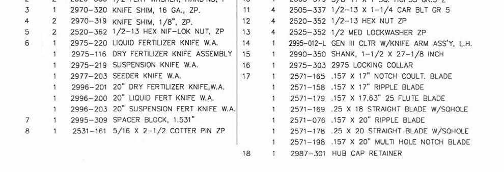
6 INSTALLATION 1. Assembly 3/8 x 2-1/2 roll pin into hole closest to end of 1-1/2 diameter shank, leaving approximately equal amount protruding out each side. Note: offset shanks require that you perform step 2 first then step Insert lock collar into pivot casting and slide shank up through casting and lock collar. If you wish to lock coulter from pivoting, slide roll pin into slots in casting. If you wish to let coulter pivot, do not align roll pin with casting slots, but slide shank up till roll pin contacts casting surface. Install and tighten 5/8 x 1 setscrew in lock collar to 110 ft. lb. torque maximum. 3. Mount 17 blade loosely to hub using four 1/2 x 1-1/2 carriage bolts, lock washers and nuts. 4. Mount fertilizer knife and spacer block to rear support arm using two 1/2 bolts lock nuts. Place shims between Spacer Block and support arm as required to align knife point with blade. 5. Center blade on hub by rotating blade and watching clearance between knife and blade. Slide blade on hub as required until clearance varies no more than 1/8 when blade is rotated one complete revolution. Tighten four 1/2 nuts. If blade-wobble is excessive, check for burrs on hub mounting surface and remove if necessary. 6. Adjust knife clearance to blade as close as possible. The high point of the blade should just clear the knife as blade is rotated. Be sure blade rotates freely then tighten two 1/2 locknuts to 120 ft. lb. Re-check clearance, by rotating blade one full revolution, after all bolts are tightened. 7. Assemble clamp components loosely to planter front bar as shown in parts view of appropriate clamp. 8. Position coulter clamps either toward the inside or outside of the planter openers on each side of the planter to equalize draft. Tighten four 1/2 nuts to secure the clamps. 9. Install coulters on planter by inserting shank up through clamps and tightening 5/8 x 1 setscrews. 10. Install 5/16 x 2-1/2 cotter pins in all vertical 1-1/2 diameter shanks. This cotter pin prevents loss of coulter should the clamp setscrews work loose. Cotter pin can be installed between clamp castings or on top, above top casting depending on the shank. 11. Set coulter depth by loosening setscrews in clamp castings. For John Deere 7000 front fold planters there may not be enough up adjustment to operate coulter at proper depth, not more than hub deep. Not all toolbars on John Deere planters operate at the same height. If necessary, cut off top of 1/12 diameter shank to allow proper adjustment. 6
7 INSTALLATION 12. On John Deere 7000 front fold planters there are two hoses that may interfere with coulter operation. Loosen hydraulic fittings and swivel hoses up out of the way to provide clearance when coulter flexes up. 13. If you have elected to let coulter swivel, set lock collar to allow swivel in one or both directions as required. If you have elected to hold coulter rigid, set coulter straight with the direction of travel. Tighten set screw to 110 ft. lb. torque maximum. 14. Set spring tension by adjusting 3/4 lock nut until 1/8 of threads are exposed above the nut. Tighten 3/4 locknut if greater spring pre-load is required. NOTE: This will reduce vertical movement of coulter. 15. NEVER mount coulters under planter drive shaft to allow coulter blades to contact shaft when an obstacle is struck. Coulters must be mounted so blade can always flex up and clear drive shaft. NOTE: Dry fertilizer must be free of chunks greater that 1/4 in size to prevent plugging. Yetter recommends using screened fertilizer or running fertilizer through screen when hoppers are filled. Clean hoppers thoroughly at the beginning of season to prevent plugging problems. The rubber dry fertilizer tube may appear to be stretched when the planter is in the transport position. This does not affect operation of the planter and should not be detrimental to the fertilizer tube. OPERATION Yetter Model Generation III fertilizer coulters are designed to apply fertilizer 3 to 5 deep. See your fertilizer dealer for recommended depth and distance away from row for your particular fertilizer. A popular placement setting is 2 below and 2 away from the seed. High deposit rates require the fertilizer to be placed farther away from the row to avoid crop burn. The coulter can be set up to swivel or not swivel as required. By not allowing the coulter to swivel, the distance between seed and fertilizer varies less when planting on contour. When mounting Model Generation III coulters on 3-point or 2-point hitch planters, the coulters should be set up to swivel, particularly if a 4-wheel drive tractor is used. This reduces the side load on the coulter during operation. It is preferable to allow the coulter to swivel. IMPORTANT: For proper operation, the planter frame must operate level and at the correct height, usually while in operation. In hard no-till conditions the desired operating depth may not be possible. Tighten spring nut to maintain depth if spring is flexing rather than lower coulter to obtain maximum depth. Planter weight may limit operating depth in hard conditions, particularly with mounted or semi-mounted planters. Be sure planter has enough weight to keep drive wheels on the ground during operation or plant populations can be drastically affected. 7
8 OPERATION 1. Set coulter blades to run vertical to ground. Operation depth and blade wear can be affected if coulter is mounted crooked. If coulters are set-up to not swivel be sure they run straight with the direction of travel. 2. After a few hours use, check all bolts and setscrews for tightness. 3. After a few days use, check coulter hubs for loose bearings. There should be no end play in the hub bearings to allow it to wobble. If necessary, remove hub cap and cotter pin, adjust slotted nut to remove wobble, re-insert cotter pin and replace hub cap. 4. KNIFE ADJUSTMENT IS CRITICAL. Adjust knife-blade clearance regularly, see page 9. An optional knife scraper, Part # or is available to reduce the frequency of adjustment on the fertilizer coulter knife. In addition this allows better operation in tough conditions such as freshly disked soils with abundant trash in the top four inches of loose soil. NOTE: A bump will appear behind knife scraper, on blade where protected, this must be ground off periodically to maintain correct knife-blade clearance. 5. BLADE WEAR can affect operation in loose trash conditions. If knife adjustment does not stop plugging problems, it may be necessary to replace blade. 6. Dry fertilizer must be free of chunks greater that 1/4 in size to prevent plugging. Yetter recommends using screened fertilizer or running fertilizer through screen when hoppers are filled. Clean hoppers thoroughly at the beginning of season to prevent plugging problems. NOTE: The rubber dry fertilizer tube may appear to be stretched when the planter is in the transport position. This does not affect operation of the planter and should not be detrimental to the fertilizer tube Knife Scraper Double Edge Knife Scraper /16-18 x 3/4 HHCS Gr. 5 ZP /16 Std. Flat washer ZP /16-18 Lock Hex Nut ZP Knife Scraper Double Edge Knife Scraper /16-18 x 3/4 HHCS Gr. 5 ZP /16 Std. Flat washer ZP /16-18 Lock Hex Nut ZP 8
9 MAINTENANCE LUBRICATION DANGER: Always install safety lock-ups or lower the planter to the ground before working on the machine. Lubricate at frequency indicated with a multi-purpose type grease. DANGER: Always install all safety lock-ups and safety lock pins before working under the toolbar. 1. Raise the toolbar until is clear off the ground. Remove the gauge wheel and the blade. Remove the hubcap, cotter pin, slotted nut and washer from the spindle shaft assembly. 2. Pull the coulter spindle shaft assembly from the hub. Remove bearing cones and cups and discard if bearings are being replaced. Clean hub and dry. Remove bearings only and not cups of re-packing. 3. Wash the old grease from the hub, bearing cups, coulter spindle shaft, seal, and bearing cones. Inspect the condition of bearing cups and cones. 4. Apply #2 multi-purpose lithium grease on each bearing. Make sure the space around each roller is filled. Lubricate the bearing cups. 5. Position the bearing in the cup and install the seal. Lubricate the seal lips and proceed with re-assembly of the removed parts including the blade. Blade bolt torque is 90 to 96 ft. lbs. 6. Install outer bearing, washer, and slotted nut. Tighten the slotted nut to 150 in. lbs. while rotating the blade or until a definite drag is felt when the blade is turned by hand. Tighten the nut one slot position to line up the cotter pin hole with a slot. Secure the nut with a new cotter pin. 9
10 KNIFE ADJUSTMENT The adjustment of knife clearance to the blade is critical to trouble free operation of the fertilizer coulter, in certain conditions the coulter can plug in just a few feet if not correctly adjusted. 1. The disc blade must run concentric. Adjust by loosening four hub nuts and centering the blade. 2. Set knife to rub slightly on blade, especially at bottom of knife. See illustrations above. Tighten lock nuts securely. 10
11 PARTS IDENTIFICATION 11
12 12 PARTS IDENTIFICATION
13 PARTS IDENTIFICATION 13
14 14 PARTS IDENTIFICATION
15 PARTS IDENTIFICATION ITEM #24 DIFFERENT BLADE OPTIONS DESCRIPTION PART NO. PART NO /8 Wave Blade (8 Wave) /8 25 Multi-Wave Blade Bubble Flute Blade Ripple Blade Wavy Blade (8 Wave) Wave Blade Multi-Wave Blade (25 Wave) Smooth Blade Ripple Blade Notched Smooth Blade DESCRIPTION Wavy Blade (8 Wave) Wave Blade Multi-Wave Blade (25 Wave) Smooth Blade Ripple Blade Smooth Blade Notched Blade Notched Bubble Blade Multi-Wave Blade (25 Wave) Smooth Blade 15
16 PARTS IDENTIFICATION SIDE KNIFE KITS Liquid Side Knife Assy., L.H Dry Side Knife Assy., L.H Liquid Side Knife Assy., R.H Dry Side Knife Assy., R.H. To be used with or blades only LH 5-1/2 Liq Side Knife Assy LH 5-1/2 Dry Side Knife Assy RH 5-1/2 Liq Side Knife Assy RH 5-1/2 Dry Side Knife Assy. To be used with blade only /2-13 x 2 HHCS Gr. 5 ZP Side Knife Shim, 1/8, ZP Side Knife Shim, 16 Ga., ZP Side Knife Brkt., /2-13 x 5 HHCS Gr. 5 ZP Liquid Side Knife Assy., R.H. (Shown) Liquid Side Knife Assy., L.H Dry Side Knife W.A., L.H Dry Side Knife W.A., R.H LH 5-1/2 Liq Side Knife S.A RH 5-1/2 Liq Side Knife S.A LH 5-1/2 Dry Side Knife W.A RH 5-1/2 Dry Side Knife W.A /2-13 Lock Hex Nut ZP /2-13 Hex Nut ZP
17 PARTS IDENTIFICATION SPRING MOUNT LIQ. FERT. INJECTOR KIT /2-13 x 1-1/2 HHCS Gr. 5 ZP /2-13 x 1 HHCS Gr. 5 ZP /2 Med. Lock washer ZP Injector Mount Plate Adjustment Plate, Injector /2-13 Hex Nut ZP Spring Injector Assembly Nipple, 1/4 NPT Stainless Steel Injector Rod W.A., 1/ /2-13 x 1-3/4 Car. Bolt Gr. 5 ZP Knife Shim, 1/8, ZP Knife Shim, 16 GA., ZP /2-13 Jam Hex Nut ZP Spacer, Injector 17
18 PARTS IDENTIFICATION SPRING MOUNT DRY INJECTOR KIT /2 Med. Lock washer ZP /2-13 Hex Nut ZP /2-13 x 1 1/2 HHCS Gr. 5 ZP /2-13 x 1 HHCS Gr. 5 ZP Injector Mount Plate Adjustment Plate, Injector Injector Spring Assembly Dry Fertilizer Adapter, PVC Spring Tine Dry Injector W.A /2-13 x 1-3/4 Car. Bolt Gr. 5 ZP Knife Shim, 1/8, ZP Knife Shim, 16 Ga., ZP /2-13 Jam Hex Nut Spacer, Injector 18
19 PARTS IDENTIFICATION Clamp Kit, 3 Diamond Bar /2-13 x 8 HHCS Gr. 5 ZP Clamp Plate, 4 Sq. or 3 Diamond Adaptor, 3 Sq. Diamond Bar Clamp Casting, Drilled /8-11 x 1 Sq. HCPSS Gr. 5 ZP /2-13 Lock Hex Nut ZP Clamp Kit, 3-1/2 Diamond Bar /2-13 x 9 HHCS Gr. 5 ZP Clamp Plate, 3-1/2 Diamond Bar Adaptor, 3-1/2 Sq. Diamond Bar Clamp Casting, Drilled /8-11 x 1 Sq. HCPSS Gr. 5 ZP /2-13 Lock Hex Nut ZP Clamp Kit, 2-1/4,2-1/2 Diamond Bar /2-13 x 7 HHCS Gr. 5 ZP Clamp Plate, 2-1/4, 2-1/2 Diamond Bar Adaptor, 2-1/4, 2-1/2 Diamond Bar Clamp Casting, Drilled /8-11 x 1 Sq. HCPSS Gr. 5 ZP /2-13 Lock Hex Nut ZP 19
20 PARTS IDENTIFICATION Clamp Kit, 2-1/2 Sq. Bar Clamp Kit, 2 x 6 Bar /2-13 x 5-1/2 HHCS GR. 5 ZP /2-13 X 5 HHCS GR. 5 ZP Clamp Plate, 2-1/2 Square Bar Clamp Plate, Universal Clamp Casting, Drilled Clamp Casting, Drilled /8-11 x 1 Sq. HCPSS Gr. 5 ZP /8-11 x 1 Sq. HCPSS Gr. 5 ZP /2-13 Hex Lock Nut ZP /2-13 Hex Lock Nut ZP Clamp Kit, 4 x 4 Bar Clamp Kit, 5 x 7 Bar /2-13 x 7 HHCS GR. 5 ZP /2-13 X 8 HHCS GR. 5 ZP Clamp Plate, 4 Sq. & 3 Diamond Bar Clamp Plate, 5 x 7 or 7x 7 Bar Clamp Casting, Drilled Clamp Casting, Drilled /8-11 x 1 Sq. HCPSS Gr. 5 ZP /8-11 x 1 Sq. HCPSS Gr. 5 ZP /2-13 Hex Lock Nut ZP /2-13 Hex Lock Nut ZP Clamp Kit, 7 x 7 Bar Clamp Kit, 3 x 7 Bar /2-13 x 10 HHCS GR. 5 ZP /2-13 X 6 HHCS GR. 5 ZP Clamp Plate, 5 x 7 or 7 x 7 Bar Clamp Plate, 5 x 7 or 7 x 7 Bar Clamp Casting, Drilled Clamp Casting, Drilled /8-11 x 1 Sq. HCPSS Gr. 5 ZP /8-11 x 1 Sq. HCPSS Gr. 5 ZP /2-13 Hex Lock Nut ZP /2-13 Hex Lock Nut ZP Clamp Kit, 3 x 3 Bar Clamp Kit, 3 x 4 Bar /2-13 x 6 HHCS GR. 5 ZP /2-13 X 6 HHCS GR. 5 ZP Clamp Plate, 3 Square Bar Clamp Plate, 4 Sq. & 3 Dmd Clamp Casting, Drilled Clamp Casting, Drilled /8-11 x 1 Sq. HCPSS Gr. 5 ZP /8-11 x 1 Sq. HCPSS Gr. 5 ZP /2-13 Hex Lock Nut ZP /2-13 Hex Lock Nut ZP 20
21 PARTS IDENTIFICATION Clamp Kit, 3 x 6 Bar Clamp Kit, 4 x 6 Bar /2-13 x 6 HHCS GR. 5 ZP /2-13 X 7 HHCS GR. 5 Zp Clamp Plate, Universal Clamp Plate, Universal Clamp Casting, Drilled Clamp Casting, Drilled /8-11 x 1 Sq. HCPSS Gr. 5 ZP /8-11 x 1 Sq. HCPSS Gr. 5 ZP /2-13 Hex Lock Nut ZP /2-13 Hex Lock Nut ZP Clamp Kit, 6 x 4 Bar Clamp Kit, 7 x 5 Bar /2-13 x 9 HHCS GR. 5 ZP /2-13 X 10 HHCS GR. 5 ZP Clamp Plate, 4 Sq. & 3 Diamond Bar Clamp Plate, 5 Sq. Bar Clamp Casting, Drilled Clamp Casting, Drilled /8-11 x 1 Sq. HCPSS Gr. 5 ZP /8-11 x 1 Sq. HCPSS Gr. 5 ZP /2-13 Hex Lock Nut ZP /2-13 Hex Lock Nut ZP Clamp Kit, 7 x 4 Bar Clamp Kit, 4 x 7 Bar /2-13 x 10 HHCS GR. 5 ZP /2-13 X 7 HHCS GR. 5 ZP Clamp Plate, 4 Sq. 3 Diamond Bar Clamp Plate, 5 x 7 or 7 x 7 Bar Clamp Casting, Drilled Clamp Casting, Drilled /8-11 x 1 Sq. HCPSS Gr. 5 ZP /8-11 x 1 Sq. HCPSS Gr. 5 ZP /2-13 Hex Lock Nut ZP /2-13 Hex Lock Nut ZP Clamp Kit, 5 x 5 Bar /2-13 x 8 HHCS GR. 5 ZP Clamp Plate, 5 Square Bar Clamp Casting, Drilled /8-11 x 1 Sq. HCPSS Gr. 5 ZP /2-13 Hex Lock Nut ZP 21
22 TROUBLESHOOTING Problem Setting coulter Trash plugging Cause Planter not set correctly Excessive knife-blade clearance Knife not correctly aligned behind blade Solution Ensure that in operation the planter frame is at correct height (20-22 ) and level the toolbar. See opposite page. Check and adjust knife-blade clearance. See page 9. Use shims to align knife behind blade Blade not penetrating Insufficient coulter spring pressure Coulter incorrectly installed Tighten coulter spring locknut down 1 further Adjust height of coulter by sliding shank down Spring not deflecting Fertilizer too deep Fertilizer too shallow Excessive spring pressure Spring not deflecting Coulter incorrectly installed Lack of depth control Planter frame too low Blade not penetrating Coulter incorrectly installed Back off coulter spring locknut to 1/8 of thread exposed Back off coulter spring locknut to 1/8 of thread exposed Adjust height of coulter by sliding shank up Install gauge wheel kit, part no Raise planter frame to correct height Tighten coulter spring locknut down 1 further Adjust height of coulter by sliding shank down Fertilizer will not flow Blade not rotating properly Plugged fertilizer tubes Loose soil Check for plugged fertilizer tube openings on knife Check for plugged fertilizer delivery tubes on planter Coulter works best in firmer soil conditions 22
23 NOTES 23
24 Our name Is getting known Just a few years ago, Yetter products were sold primarily to the Midwest only. Then we embarked on a program of expansion and moved into the East, the South, the West and now north into Canada. We re even getting orders from as far away as Australia and Africa. So, when you buy Yetter products...you re buying a name that s recognized. A name that s known and respected. A name that s become a part of American agriculture and has become synonymous with quality and satisfaction in the field of conservation tillage. Thank you. YETTER MANUFACTURING CO. Colchester, IL / Toll Free 800/ Fax 309/ Website: info@yetterco.com 07/ _REV_D 24
3000 SERIES VIPER II FERTILIZER COULTER
 3000 SERIES VIPER II FERTILIZER COULTER OPERATOR S MANUAL PART IDENTIFICATION 2565-690_REV_H 10/2013 YETTER MANUFACTURING CO. FOUNDED 1930 Colchester, IL 62326-0358 Toll free: 800/447-5777 309/776-3222
CHANGING YOUR LANDSCAPE SINCE 1945 OWNER S MANUAL. Tow Hitch Replacement Kit For Rough Cut Trailcutters. Starting Serial # L
 CHANGING YOUR LANDSCAPE SINCE 1945 OWNER S MANUAL Tow Hitch Replacement Kit For Rough Cut Trailcutters 21100 Starting Serial # L118-023001 Tools Required: Wrench/Socket Qty. Size (1) 1-1/8 (1) 1-1/16 (2)
PARTS BOOK FLAIL HEADS 90 REAR 3PT HITCH MOUNT
 PARTS BOOK FLAIL HEADS 90 REAR 3PT HITCH MOUNT 5.0.8 DIAMOND MOWERS, LLC 350 E 60 th St. North Sioux Falls, SD 5704 FOR WARRANTY CALL DIAMOND MOWERS DIRECT: 888-960-0364 OUR TECHNICIANS WILL DIAGNOSE YOUR
INSTRUCTIONS INSTALLATION UNIVERSAL SERIES PATIO AWNING HARDWARE , , ,
 RECORD THIS INFORMATION FOR FUTURE REFERENCE: Model Number Serial Number Hardware Model Number Hardware Serial Number Date Purchased Retailer / Qualified Installer INSTALLATION INSTRUCTIONS UNIVERSAL SERIES
Shut off combine and remove key before installing the hopper extension. Make sure the combine is on a level surface. Engage parking brake.
 ASSEMBLY INSTRUCTIONS CASE IH 5088, 6088/7088, 7010/8010 & 7120/8120/9120 Series NEW HOLLAND CR STD Series Combines (Large) big top 26301(service only), 29976 (service only), 53408, 53543 & 54274 The Crary
DeZURIK AM-SERIES MANUAL GEAR ACTUATOR USED ON BUTTERFLY VALVES
 AM-SERIES MANUAL GEAR ACTUATOR USED ON BUTTERFLY VALVES Instruction D10501 January 2015 Instructions These instructions provide information about AM-Series Manual Actuators used on Butterfly Valves. They
PARTS BOOK CATALOG SIDE HD FLAIL HEADS TRACTOR MID-MOUNT
 PARTS BOOK CATALOG SIDE HD FLAIL HEADS TRACTOR MID-MOUNT DIAMOND MOWERS, Inc. 350 E 60 th St. North Sioux Falls, SD 57104 FOR WARRANTY CALL DIAMOND MOWERS DIRECT: 888-960-0364 OUR TECHNICIANS WILL DIAGNOSE
UTV BLADE MOUNT HARDWARE
 1701 38TH AVE W PO BOX 257 SPENCER, IA 51301 PHONE: 712-262-4191 FAX: 712-262-0248 SERVICE: 800-841-2222 E-MAIL: ccac@cyclecountry.com UTV BLADE MOUNT HARDWARE For the KUBOTA RTV900 OWNER S MANUAL MODEL
BowDown. MiniMuM Crossbar spread 24 (61CM) Steel Hook (2X) Buckle Strap (2X) Plastic Tube (2X) Plain Strap (2X) SHORT BLACK T-BOLT (2x) BOWDOWN (2x)
 Steel Hook (2X) Buckle Strap (2X) Plastic Tube (2X) Plain Strap (2X) SHORT BLACK T-BOLT (2x) BOWDOWN (2x)") BowDown MiniMuM Crossbar spread 24 (61CM) Heavy Duty strap (2x) SHORT BLACK T-BOLT (2x) BOWDOWN (2x) Bow Stern Tie Down Buckle Strap (2X) Plastic Tube (2X) Plain Strap (2X) Steel Hook (2X) IMPORTANT WARNING
BowDown MiniMuM Crossbar spread 24 (61CM) Heavy Duty strap (2x) SHORT BLACK T-BOLT (2x) BOWDOWN (2x) Bow Stern Tie Down Buckle Strap (2X) Plastic Tube (2X) Plain Strap (2X) Steel Hook (2X) IMPORTANT WARNING
RAFTER VI. Installation and Operation CAREFREE WITH AUTOMATIC AWNING SUPPORT. RV Accessory PRODUCT OVERVIEW
 CAREFREE RAFTER VI RV Accessory WITH AUTOMATIC AWNING SUPPORT Installation and Operation PRODUCT OVERVIEW The gives the awning user the ability to easily tighten the center fabric when the awning is extended.
UTV SNOW FORCE TM PUSH TUBE KIT OWNER S MANUAL
 1701 38TH AVE W PO BOX 257 SPENCER, IA 51301 PHONE: 712-262-4191 FAX: 712-262-0248 SERVICE: 800-841-2222 E-MAIL: ccac@cyclecountry.com www.cyclecountry.com UTV SNOW FORCE TM PUSH TUBE KIT OWNER S MANUAL
Tidland Series 'C' Knifeholder MAINTENANCE MANUAL Crush Cartridge Class I, II, III Crush Slitting
 Tidland Series 'C' Knifeholder MAINTENANCE MANUAL Crush Cartridge Class I, II, III Crush Slitting Please read and understand all the instructions before you start to maintain the Tidland Series 'C' Knifeholder.
300 ft. 5/8 Hose wagon
 300 ft. 5/8 Hose wagon Model 95956 Assembly And Operation Instructions Due to continuing improvements, actual product may differ slightly from the product described herein. (Garden hose is not included).
Thomas Scientific Swedesboro, NJ U.S.A.
 Thomas Scientific Swedesboro, NJ 08085-0099 U.S.A. Wiley Laboratory Mill, Model 4 3375-E10 (115 V, 50/60 HZ) USE AND CARE OF CATALOG NUMBER: 3375-E10 Wiley Laboratory Mill, Model 4 (115 V, 50/60 HZ) UNPACKING
DC 700 Series Hose Reel - September 2010
 Instructions Parts List Service Manual DC 700 Series Hose Reel - September 2010 Suitable for dispensing, transfer and evacuation of lubricants, fuels, air & other automotive & industrial products. To be
STOP BOX SCRAPER/GRADER BLADE. Owner's Manual. Model No Safety Assembly Operation Maintenance Parts
 Owner's Manual STOP BOX SCRAPER/GRADER BLADE Model No. 486.242411 DO NOT RETURN TO STORE For Missing Parts or Assembly Questions Call 1-866-576-8388 CAUTION: Before using this product, read this manual
4A1-114/114KR & 4A1-2 MANUAL TENSIONERS
 M L. C O O N AL TO 4A1-114/114KR & 4A1-2 W W W.T R AD IT IO MANUAL TENSIONERS READ THESE INSTRUCTIONS CAREFULLY. FAILURE TO FOLLOW THESE INSTRUCTIONS CAN RESULT IN SEVERE PERSONAL INJURY. GENERAL SAFETY
READ ME! IMPORTANT WARNING! ENG. Quick Release Tent Mount Kit
 Quick Release Tent Mount Kit ENG TBMK008 READ ME! Thank you for purchasing a Front Runner Quick Release Tent Mount Kit. Before you start, take a moment to familiarize yourself with the Fitting Instructions
NS 200 Series Hose Reel January 2011
 Instructions Parts List Service Manual NS 200 Series Hose Reel January 2011 Suitable for dispensing, transfer and evacuation of lubricants, fuels, air & other automotive & industrial products. To be used
Advantage Plus TIM-3600 Series Reel
 Read the following precautions and instructions before you begin assembly or using. Failure to comply with these instructions could result in personal injury or property damage. Keep these instructions
TITAN Fuel Tanks. INSTALLATION INSTRUCTIONS G e n e r a t i o n V
 TITAN pt. no.: 02 0000 0128 Important: Please read these instructions carefully and completely before starting the installation. TITAN Fuel Tanks INSTALLATION INSTRUCTIONS G e n e r a t i o n V Extended
INSTALLATION INSTRUCTIONS AND OWNER'S MANUAL AWNINGS. For trailers & motor homes with straight sides TOOLS REQUIRED
 AWNINGS INSTALLATION INSTRUCTIONS AND OWNER'S MANUAL For trailers & motor homes with straight sides TOOLS REQUIRED 1/4" electric drill Ratchet handle kit 3/8" & 7/16" socket No. 1 and No. 2 screwdriver
INSTRUCTION SHEET DETHATCHER KIT. STS-422LX LPSTS-42JD Assembly Installation Operation Repair Parts L-1660-D. Visit us on the web!
 INSTRUCTION SHEET DETHATCHER KIT MODEL: DK-422LX FOR USE WITH SWEEPER MODEL: STS-422LX LPSTS-42JD Assembly Installation Operation Repair Parts For use with Riders and Lawn/Garden Tractors For the latest
Urea/Adblue Hose Reel
 www.scintex.com.au sales@scintex.com.au Model: SHR3408 Urea/Adblue Hose Reel Product Manual Specifications Spring driven drum: for automatic rewind. Locking ratchet: to maintain the desired length of hose
Swagelok Thermoplastic Hose Hand Swager User s Manual
 Swagelok Thermoplastic Hose Hand Swager User s Manual Thermoplastic Hose Hand Swager User s Manual Contents Hand Swager Components....................... 2 Setup Swager.......................................
SPIRAL SLICER Instruction Manual Model #5280 & 5280M. Part No Revised Feb. 2010
 SPIRAL SLICER Instruction Manual Model #5280 & 5280M Part No. 82876 Revised Feb. 2010 SAFETY PRECAUTIONS INSTALLATION INSTRUCTIONS Inspection of Shipment: 5280 & 5280M SPIRAL SLICER Unpack all cartons
MAX Series 9514 OPERATOR S MANUAL
 MAX Series 9514 OPERATOR S MANUAL Persons under age 18 are not permitted to operate or have accessibility to operate this equipment per U.S. Dept. Of Labor Employment Standards Administration Fact Sheet
42" SNOW BLADE. Owner's Manual. Model No Safety Assembly Operation Maintenance Parts
 Owner's Manual 42" SNOW BLADE Model No. 486.24443 CAUTION: Before using this product, read this manual and follow all Safety Rules and Operating Instructions. Safety Assembly Operation Maintenance Parts
, & Series Nested Hardware
 RECORD THIS INFORMATION FOR FUTURE REFERENCE BEFORE INSTALLING THE UNIT: Model Number Serial Number Date Purchased Place of Purchase USA SERVICE OFFICE Dometic Corp. 509 So. Poplar St. LaGrange, IN 46761
AND LOAD CANOPY RACK SPECIFICATIONS
 8MAY15 INSTRUCTIONS for the LOCK AND LOAD CANOPY RACK SPECIFICATIONS and SAFE LOADING REQUIREMENTS The Lock and Load ladder carrier for Truck Caps is a rack designed to mount to the top of a pickup truck
Hose Reel Series L701/G701
 Hose Reel Series L70/G70.0 WARNING: Read carefully and understand all INSTRUCTIONS before operating. Failure to follow the safety rules and other basic safety precautions may result in serious personal
TIN KNOCKER TK NO. 30 CLEAT BENDER INSTRUCTIONS & PARTS DIAGRAM. TK No. 30 CLEAT BENDER
 1 TIN KNOCKER TK NO. 30 CLEAT BENDER INSTRUCTIONS & PARTS DIAGRAM TK No. 30 CLEAT BENDER Sheet Metal Equipment Sales Inc. Dean P. O'Connell, President Green Bay, Wisconsin Phone - (920)-662-9966 Fax -
1000M MANUAL Signature Series Slicer OPERATORS MANUAL
 1000M MANUAL Signature Series Slicer OPERATORS MANUAL Persons under age 18 are not permitted to operate or have accessibility to operate this equipment per U.S. Dept. Of Labor Employment Standards Administration
Eaton ET Hydraulic Hose Saw INSTRUCTION MANUAL
 Eaton ET9100-07-110 Hydraulic Saw INSTRUCTION MANUAL INSTRUCTION MANUAL Eaton ET9100-07-110 Hydraulic Saw Table of Contents Introduction... 3 Old Method... 3 New Eaton Method... 3 Operation... 4 Operation
KAWASAKI MULE 610 WINCH MOUNT KIT. Owner s Manual
 1701 38TH AVE W PO BOX 257 SPENCER, IA 51301 PHONE: 712-262-4191 FAX: 712-262-0248 SERVICE: 800-841-2222 E-MAIL: ccac@cyclecountry.com KAWASAKI MULE 610 WINCH MOUNT KIT Owner s Manual MODEL NUMBER: 25-2200
IMPORTANT OWNER-OPERATOR INSTALLATION INSTRUCTIONS C2204A
 IMPORTANT OWNER-OPERATOR INSTALLATION INSTRUCTIONS C2204A Warnings Truck Bed and Camper Protection Torklift does not recommend installing your camper on top of a plastic bed liner (or other compressible
HARD DOOR UPGRADE KIT
 RV Accessories OWNER'S MANUAL HARD DOOR UPGRADE KIT FOR ADD-A-ROOM & BREEZEWAY SCREEN ROOMS THIS MANUAL SUPPLEMENTS THE ADD-A-ROOM INSTRUCTIONS TABLE OF CONTENTS First Time Assembly... 2 Assembling the
W & A PARTS MANUAL LEVEE PLOW STANDARD. Model No Blade Model No Blade (Parts Only)
") W & A PARTS MANUAL LEVEE PLOW STANDARD Model No. 824 -- 8 Blade Model No. 836 -- 10 Blade (Parts Only) SPECIALIZED FARM EQUIPMENT Quality Products from W & A MANUFACTURING COMPANY P.O. Box 5238, Pine Bluff,
W & A PARTS MANUAL LEVEE PLOW STANDARD Model No. 824 -- 8 Blade Model No. 836 -- 10 Blade (Parts Only) SPECIALIZED FARM EQUIPMENT Quality Products from W & A MANUFACTURING COMPANY P.O. Box 5238, Pine Bluff,
Meat Slicer INSTRUCTION MANUAL CAUTION! ONE YEAR LIMITED WARRANTY
 ONE YEAR LIMITED WARRANTY INSTRUCTION MANUAL The original registered owner of this product should contact SKYFOOD EQUIPMENT LLC at 305-868-16 for any warranty problems or service. SKYFOOD EQUIPMENT LLC
front runner READ ME! IMPORTANT WARNING! ENG Foxwing Awning Brackets
 front runner Foxwing Awning Brackets ENG RRAC0 READ ME! Thank you for purchasing Front Runner Foxwing Awning Brackets. Before you start, take a moment to familiarize yourself with the Fitting Instructions
YAMAHA WINCH MOUNT KIT. Installation Instructions KIT NUMBER:
 YAMAHA WINCH MOUNT KIT Installation Instructions KIT NUMBER: 25-5160 CUSTOMER MUST RECEIVE A COPY OF THIS INSTRUCTION MANUAL AT TIME OF SALE 2005 CYCLE COUNTRY ACCESSORIES CORP. Rev. 2 9/22/06 Please Note:
NEW Super Long Life. Exceptional Wear Protection Avaliable on selected points
 2017 PRODUCT & PRICE GUIDE OCT 2016 - SEP 2017 ALL PRICES RRP AND EXCLUDE GST NEW Super Long Life Extra Tungsten Extra Hardfacing Exceptional Wear Protection Avaliable on selected points Point Boot Kits
ALPINE SLIDEOUT COVER
 INSTALLATION MANUAL ALPINE SLIDEOUT COVER RV Read this manual before installing or using this product. Failure to follow the instructions and safety precautions in this manual can result in personal injury
Operating Instructions
 Operating Instructions Medium and High Pressure Model Numbers: RT602- RT635- RT602- RT635- RT603- RT650- RT603- RT650- RT605- RT825- RT605- RT650-SM RT802- RT835- RT425- RT803- RT402- RT435- RT625- RT403-
Assembly TOOLS REQUIRED: 17mm and 14mm or equivalent wrenches.
 Instructions for 3 Trimmer Rack, 3TR* *Patents Pending Assembly TOOLS REQUIRED: 17mm and mm or equivalent wrenches. 15 26 26 16 15 16 Attach the lower mounting brackets to the Trimmer Rack poles as shown
INSTALLATION INSTRUCTIONS for folding arm awnings
 Custom made Awnings and Blinds Item No 0757 INSTALLATION INSTRUCTIONS for folding arm awnings IMPORTANT INFORMATION BEFORE INSTALLING YOUR Updated 08/09/15 AN AWNING INSTALLATION IS A HOME IMPROVEMENT
IMPORTANT OWNER-OPERATOR INSTALLATION INSTRUCTIONS D3109. REVISED vers10 BY: DSK 1/9/2015 TECH SUPPORT (800)
") IMPORTANT OWNER-OPERATOR INSTALLATION INSTRUCTIONS D3109 REVISED vers10 BY: DSK 1/9/2015 TECH SUPPORT (800) 246-8132 AFTER INSTALL, PLEASE GIVE THIS BOOKLET TO YOUR CUSTOMER 1 Warnings Truck Bed and Camper
IMPORTANT OWNER-OPERATOR INSTALLATION INSTRUCTIONS D3109 REVISED vers10 BY: DSK 1/9/2015 TECH SUPPORT (800) 246-8132 AFTER INSTALL, PLEASE GIVE THIS BOOKLET TO YOUR CUSTOMER 1 Warnings Truck Bed and Camper
AUTO REWIND HOSE REEL WITH 50 FOOT HOSE. Model 46320
 AUTO REWIND HOSE REEL WITH 50 FOOT HOSE Model 46320 ASSEMBLY AND OPERATING INSTRUCTIONS 3491 Mission Oaks Blvd., Camarillo, CA 93011 Visit our Web site at http://www.harborfreight.com Copyright 2001 by
Assembly and Installation Instructions
 U.S. patent number 8,708,369 part number 4750 for Blue Ox tow bars with Blue Ox brackets, Demco tow bars with Demco brackets, and all motorhome-mounted ROADMASTER tow bars Assembly and Installation Instructions
* * KR54-F, KR9854 & KR9954 Installation Instructions. Read All Warnings Before Starting Installation! Index:
 *941061-00* 941061-00 Keyed Removable Mullion KR54-F, KR9854 & KR9954 Installation Instructions CLASSIFIED CLASSIFIED C Read All Warnings Before Starting Installation! Index: General Information ----------------
BigStack. Minimum Crossbar spread 24 For factory racks: Check fitlist notes, or Yakima.com for your vehicle s crossbar spread.
 BigStack Minimum Crossbar spread 24 For factory racks: Check fitlist notes, or Yakima.com for your vehicle s crossbar spread. HEAVY Duty strap (2x) PAD (4x) ADJUSTMENT KNOB (2x) T-BOLT (2x) BAIL (2x) BigStack
IMPORTANT OWNER-OPERATOR INSTALLATION INSTRUCTIONS. Part # A7006
 IMPORTANT OWNER-OPERATOR INSTALLATION INSTRUCTIONS Part # A7006 Parts List Wobble Stopper Body Wobble Stopper Shaft Camper Bracket Lower Bracket Assembly Upper Bracket Upper Bracket Clamp 3/8 SAE Flat
ADDED PROTECTION FOR SLIDE-OUT ROOMS. Installation. Introduction... 2 Product Overview...2 Component Checklist...3
 CAREFREE SIDEOUT KOVER II RV Installation ADDED PROTECTION FOR SLIDE-OUT ROOMS TABLE OF CONTENTS SOKII Shown with Full Case Option Introduction... 2 Product Overview...2 Component Checklist...3 Installation...
FIESTA & FIESTA HD PATIO AWNINGS
 INSTALLATION MANUAL FIESTA & FIESTA HD PATIO AWNINGS MANUALLY OPERATED PATIO AWNING RV Read this manual before installing or using this product. Failure to follow the instructions and safety precautions
Assembly and Installation Instructions
 U.S. patent number 8,708,369 part number 4750 for Blue Ox tow bars with Blue Ox brackets, Demco tow bars with Demco brackets, and all motorhome-mounted ROADMASTER tow bars Assembly and Installation Instructions
NEWMAR SERVICE SCHOOL
 NEWMAR SERVICE SCHOOL TRAINING INFORMATION GUIDELINE FOR FEBRUARY 2013 OUR PRODUCTS: NOVA DUAL PITCH AWNING G-2000/ G-1500 2 P a g e G-2085 G-5000 3 P a g e G-LINKS 4 P a g e NOVA/ G-2000/ G-1500 BASIC
Operation Manual SUPER BEAST Multi-tool SC-11M-10
 Operation Manual SUPER BEAST Multi-tool SC-11M-10 Technical Specifications General Safety/Operating Instructions Attaching/Changing the Head Using the SUPER BEAST as a Cutter Using the SUPER BEAST as a
INSTRUCTION MANUAL HYDM140
 INSTRUCTION MANUAL HYDM140 INSTRUCTION MANUAL Clean-Cuts HYDM140 Hydraulic Hose Saw Table of Contents Introduction... 3 Old Method... 3 New Clean-Cuts Method... 3 Operation... 4 Operation Procedure...
Tri-Glide Instruction Manual
 Tri-Glide Instruction Manual 12 Timber Lane Marlboro NJ 07746 09/09/2011 tel: 732.462.6277 fax:732.462.6355 email: sales@hilmanrollers.com CONTENTS Contents Page Warnings 3 Operating Instructions 4 General
Door Bushing Replacement & Latch Adjustment Monaco Group Coaches
 Door Bushing Replacement & Latch Adjustment Monaco Group Coaches Contents Door Latch Adjustment & Repair... 1 Symptoms:... 1 Replacing the bushing VS. Adjusting the latch rods.... 1 How the bushing works....
Operating Instructions
 Operating Instructions Series RT Spring Driven Hose Reels Low Pressure Model Numbers: RT402-OLP RT605-OLP RT450-OLP RT835-OLP RT403-OLP RT802-OLP RT465-OLP RT850-OLP RT405-OLP RT803-OLP RT625-OLP RT450-OLPSM
AFC-50 Automatic French Fry Cutter Instruction Manual
 AFC-50 Automatic French Fry Cutter Instruction Manual Fry Factory Inc. 67 Watts Ave, Charlottetown, PEI, C1E 2B7, Canada Phone: 902-368-2900 Fax: 902-368-8645 Email: info@fryfactoryinc.com Website: www.fryfactoryinc.com
HAND HELD BALL VALVE & DETENT STYLE BALL VALVES
 HAND HELD BALL VALVE & DETENT STYLE BALL VALVES SERVICE PROCEDURE D SERIES J40 SERIES H-VO SERIES D00D SERIES J40 SERIES H-VO SERIES F00 SERIES H-VIT SERIES H-VO SERIES F SERIES F40 SERIES HVIT SERIES
Tarp Return. Questions? Contact Customer Or Parts Diagrams see Parts and Diagrams section on web at
 Roll Rite, LLC and its entire staff would like to not only Thank You but congratulate you on your purchase of one of what we feel to be the finest line of tarping systems in the industry. Tarp Return RR
CRD120SC TUBING CUTTER
 CRD120SC TUBING CUTTER OPERATIONS MANUAL 1 VERSION 2.1 LAST EDITED 05.01.2018 cleanroomdevices.com Table of Contents Table of Contents....2 1.0 General Product & Safety Information... 3 1.1 Product Information
DIAMOND TECH INTERNATIONAL Innovations For Creativity DIAMOND LASER BAND SAW OPERATIONS MANUAL
 SPEEDSTER-XL INSTRUCTION MANUAL DIAMOND TECH INTERNATIONAL Innovations For Creativity SPEEDSTER-XL DIAMOND LASER BAND SAW OPERATIONS MANUAL SPEEDSTER-XL INSTRUCTION MANUAL - PAGE 1 Before You Begin Read
PRODUCT MANUAL - M096
 PRODUCT MANUAL - M096 MODEL 270 ELECTRIC CAN OPENER 1 I. LABELS L087--CAUTION 2 II. SPECIFICATIONS MODEL NO. 270 POWER 115 VOLT, 1.5 AMP, 50-60HZ REQUIREMENTS 230 VOLT, 0.8 AMP, 50-60 HZ NORMAL SPEED 200-250
BR B Bike Rack Instructions
 IMPORTANT NOTE: It is common that vehicles with lids and hatches have a single rear wiper. It is important that you make yourself aware that the wiper cannot be used while the rack is attached to the vehicle.
PS-10 PS-12D PS-12. Primo Slicer Manual FOR OPERATOR-DO NOT DISCARD
 PS-10 PS-12D PS-12 Primo Slicer Manual FOR OPERATOR-DO NOT DISCARD TABLE OF CONTENTS 1. BRIEF INTRODUCTION 2. OPERATION 3. SLICING 4. MAINTENANCE AND CLEANING 5. TROUBLESHOOTING IMPORTANT The operator
READ ME FIRST! IMPORTANT WARNING! ENG. Roof top tent
 Roof top tent ENG TENT031 220 min READ ME FIRST! Thank you for purchasing a Front Runner Roof Top Tent. Before you start, take a moment to familiarize yourself with these Fitting Instructions and the components
Installation. Introduction... 2 Product Overview...2 Component Checklist...3
 CAREFREE SIDEOUT KOVER II RV WITH MANUAL LOCK Installation TABLE OF CONTENTS Introduction... 2 Product Overview...2 Component Checklist...3 Installation... 4 Installing the Mounting Brackets...4 Assemble
* * 4023 KR. Step 1 Prepare the Keyed Removable Unit. Not for use on electric or fire rated removable mullions
 condition. *64009-00* 64009-00 Keyed Removable Mullions 403 KR Installation Instructions Not for use on electric or fire rated removable mullions This kit includes the following parts: (Not to scale) 5/6
WIDESPREAD LAVATORY MODELS WITH HI-ARC SPOUT
 5951, 5961, 5981, 5983, 5993 SERIES MT122B INSTALLATION INSTRUCTIONS THESE INSTRUCTIONS MUST BE LEFT WITH HOMEOWNER WIDESPREAD LAVATORY MODELS WITH HI-ARC TRADITIONAL CROSS NOTE: Handle Inserts are not
HAND HELD BALL VALVE & DETENT STYLE BALL VALVES
 HAND HELD BALL VALVE & DETENT STYLE BALL VALVES SERVICE PROCEDURE D75 SERIES J40 SERIES H-VO SERIES D00D SERIES J40 SERIES H-2VO SERIES F00 SERIES H-VIT SERIES H-VO SERIES F40 SERIES HVIT SERIES TASK FORCE
IMPORTANT OWNER-OPERATOR INSTALLATION INSTRUCTIONS. Part # C3206. REVISED Version 6 BY: JL 8/5/2015 TECH SUPPORT (800)
") IMPORTANT OWNER-OPERATOR INSTALLATION INSTRUCTIONS Part # C3206 REVISED Version 6 BY: JL 8/5/2015 TECH SUPPORT (800) 246-8132 Warnings Truck Bed and Camper Protection Torklift does not recommend installing
IMPORTANT OWNER-OPERATOR INSTALLATION INSTRUCTIONS Part # C3206 REVISED Version 6 BY: JL 8/5/2015 TECH SUPPORT (800) 246-8132 Warnings Truck Bed and Camper Protection Torklift does not recommend installing
80070 TOP MOUNT CAMPER SHELL and TRANSIT CONNECT RACK TMCS_3:1
 ASSEMBLY INSTRUCTIONS for : 80070 TOP MOUNT CAMPER SHELL and TRANSIT CONNECT RACK TMCS_3:1 (916) 638-8703 (800) 343-7486 11261 Trade Center Drive Rancho Cordova, CA 95742 www.kargomaster.com Transit ASSEMBLY
READ AND SAVE THESE INSTRUCTIONS! EasyAwn Spear Awning Installation
 EasyAwn Installation, Care and Maintenance Manual EasyAwn Quality, Since 1946 EasyAwn, LLC Toll Free: 877-EasyAwn http://www.easyawn.com READ AND SAVE THESE INSTRUCTIONS! EasyAwn Spear Awning Installation
INSTALLATION INSTRUCTIONS
 INSTALLATION INSTRUCTIONS KR54, KR1654, & KR4954 Keyed Removable Mullion NOT FOR USE ON ELECTRIC OR FIRE RATED MULLIONS. This kit includes the following parts: (Not to scale) WARNING Remove key, reinstall,
DO NOT USE WITH CROSSBAR SPREAD LESS THAN 24.
 TM Please read all instructions carefully before assembly, installation and/or use of this product. DO NOT USE WITH CROSSBAR SPREAD LESS THAN 24. WARNING: Do not exceed the weight limit of your vehicle
1946 READ AND SAVE THESE INSTRUCTIONS!
 EasyAwn Installation, Care and Maintenance Manual EasyAwn Quality, Since 1946 EasyAwn, LLC Toll Free: 877-EasyAwn http://www.easyawn.com READ AND SAVE THESE INSTRUCTIONS! EasyAwn Quarter Round Awning Installation
JARVIS. Model 70 Airsnip Air Powered Scissors
 Air Powered Scissors EQUIPMENT SELECTION... Ordering No. Airsnip Model 70... 4019009 Air Filter/Regulator/Lubricator.. 3022003 Balancer... 1350084 Power--Pak (250 PSI)... 4026016 TABLE OF CONTENTS... Page
Aftermarket Installation Manual
 Straptek Installation Manual Table of Contents Introduction... 2 Straptek Weight Tension Technology.... 2 Disadvantages with Typical Weight Distribution Systems (WDS)... 2 Straptek Advantages:... 2 Quick
1612P MODEL 1612P SLICER MODEL EXECUTIVE OFFICES 701 RIDGE AVENUE TROY, OHIO FORM (4-95)
") 1612P MODEL 1612P SLICER MODEL 1612P ML-104587 EXECUTIVE OFFICES 701 RIDGE AVENUE TROY, OHIO 45374-0001 FORM 19370 (4-95) Installation, Operation, and Care of MODEL 1612P SLICER SAVE THESE INSTRUCTIONS
1612P MODEL 1612P SLICER MODEL 1612P ML-104587 EXECUTIVE OFFICES 701 RIDGE AVENUE TROY, OHIO 45374-0001 FORM 19370 (4-95) Installation, Operation, and Care of MODEL 1612P SLICER SAVE THESE INSTRUCTIONS
LDR Brachytherapy Seed Sterilization and Sorting Tray
 LDR Brachytherapy Seed Sterilization and Sorting Tray Table of Contents General Precautions... 2 Customer Responsibility... 3 Description... 4 Features and Specifications... 5 Operation... 6 Changing Covers
VISIT OUR WEBSITE: OR CALL US TOLL FREE AT
 Model #710 WATH THE VIEO Owner s Manual VISIT OUR WEBSITE: WWW.LIBERTYGARENPROUTS.OM OR ALL US TOLL FREE AT 1-866-820-5805 LIBERTY GAREN PROUTS, IN. 1161 SOUTH PARK RIVE, KERNERSVILLE N 27284 IMPORTANT:
Installation and User s Manual 12 x 10 MOTORIZED AWNING
 12 x 10 MOTORIZED AWNING Installation and User s Manual 12 x 10 MOTORIZED AWNING 088-1763-0 Stop Please read and understand this manual before any assembly or use of this product. Before beginning assembly
RETRACTABLE AWNING w/ OPTIONAL HOOD ASSEMBLY INSTRUCTIONS
 Contact us @ (800)851-0865 RETRACTABLE AWNING w/ OPTIONAL HOOD ASSEMBLY INSTRUCTIONS Congratulations on your purchase of a new retractable awning. With proper installation this awning will provide years
Mixer Blade Sets of Parts and Installation Procedure Using Epoxy
 Mixer Blade Installation Procedure Important Safety Notice STAY CLEAR OF MIXER UNTIL MIXER IS OFF, MAIN PANEL IS LOCKED OUT, AND ALL MIXER COMPONENTS' MOTIONS ARE STOPPED. FOLLOW STANDARD SAFETY PROCEDURES
Cloze Control Installation Instructions I001 June 2016
 Cloze Control Installation Instructions 99-22095-I001 June 2016 *Cloze Control shown here with no grease (Refer to page 8 for clarification on proper grease and application) Order replacement parts today,
OPERATION MANUAL 14 Rigging Sheave Manufactured by Wireline Technologies, Inc. Serial Number
 OPERATION MANUAL 14 Rigging Sheave Manufactured by Wireline Technologies, Inc. Serial Number Introduction This manual explains the use and care of 14 rigging sheaves manufactured by Wireline Technologies,
Solera Classic Awning OEM INSTALLATION MANUAL
 Solera Classic Awning OEM INSTALLATION MANUAL TABLE OF CONTENTS System and Safety Information 2 Preparation 3 Resources Required 3 Installation 3 Installing the Awning Rail (If Necessary) 3 Assembling
READ AND SAVE THESE INSTRUCTIONS! EasyAwn Standard Awning Installation
 EasyAwn Installation, Care and Maintenance Manual EasyAwn Quality, Since 1946 EasyAwn, LLC Toll Free: 877-EasyAwn http://www.easyawn.com READ AND SAVE THESE INSTRUCTIONS! EasyAwn Standard Awning Installation
Model 698/ and Model in 1 Hose Reel Owner s Manual
 Model 698/694 200 and Model 706 100 4 in 1 Hose Reel Owner s Manual 698/694 706 VISIT OUR WEBSITE: WWW.LIBERTYGARDENPRODUCTS.COM OR CALL US TOLL FREE AT 1-866-820-5805 LIBERTY GARDEN PRODUCTS, INC. 500
BERYL Service Guide. Travel Adjust OTT Change
 BERYL Service Guide Travel Adjust OTT Change SERVICE OVERVIEW This manual will guide you step by step performing a travel adjust and OTT setting change to your Beryl suspension fork. Please follow each
Model INSTALLATION INSTRUCTIONS
 RECORD THIS UNIT INFORMATION FOR FUTURE REFERENCE: Model Number Serial Number Date Purchased USA SERVICE OFFICE Dometic, LLC 2320 Industrial Parkway Elkhart, IN 46516 574-294-2511 895(X)0(X)1.400(X) Basement
DO NOT use Alien Flier Zip Line Products until you have read and fully understand the SAFETY WARNINGS below!
 SAFETY WARNING DO NOT use Alien Flier Zip Line Products until you have read and fully understand the SAFETY WARNINGS below! Assumption of Risk Zip line construction and use can be dangerous. Ensure you
PR-429BF-600M. Bell 429 Blade Fold Kit Operations Manual
 Table of Contents Table of Contents... 1 Record of Revisions... 2 References... 3 Introduction... 4 Contact Information... 4 Prerequisites... 5 First Time Use... 6 Blade Clamp Placement... 6 Blade Clamp
Solera Classic Awning
 Solera Classic Awning OWNER'S MANUAL Page 1 Table of Contents System and Safety Information 2 Operation 3 Extending the Awning 3 Optional Car Port Position 3 Retracting the Awning 3 Fabric Replacement
Eaton ET Hydraulic Hose Saw INSTRUCTION MANUAL
 Eaton ET9200-10-220 Hydraulic Hose Saw INSTRUCTION MANUAL INSTRUCTION MANUAL Eaton ET9200-10-220 Hydraulic Hose Saw Table of Contents Introduction... 3 Old Method... 3 New Eaton Method... 3 Operation...
Auxiliary 63.5l Fuel Tank Ford/Mazda Pick-up Truck 2012-Current READ ME! IMPORTANT WARNING!
 Auxiliary 63.5l Fuel Tank Ford/Mazda Pick-up Truck 2012-Current ENG FTFM006 90 min READ ME! Thank you for purchasing a Front Runner Ford/Mazda Pick-Up Truck 2012 - Current Fuel Tank. Before you start,