By Ray Grissom. Builder s Guide
|
|
|
- Pauline Gabriella Cameron
- 6 years ago
- Views:
Transcription


1 By Ray Grissom Builder s Guide
2
3 Contents Preface...2 Grade Level Appropriateness...2 Using This Guide...3 Safety Information...4 Parts Identification Student Parts Assemblies...9 Remote Control Setup Construction Tips Wheelee Bot Assembly Activities Gripper Assembly Buggee Bot Assembly Activities Buggee Bot Moving Gripper Assembly Pickee Bot Assembly Activities Accessories Section Ball Rack Assembly Written by Ray Grissom. Content advising by Paul Uttley. Graphics by Todd McGeorge Pitsco, Inc., 915 E. Jefferson, Pittsburg, KS All rights reserved. This product and related documentation are protected by copyright and are distributed under licenses restricting their use, copying, and distribution. No part of this product or related documentation may be reproduced in any form by any means without prior written authorization of Pitsco, Inc. All other product names mentioned herein might be the trademarks of their respective owners. Note about photocopying: By honoring our copyright, you enable us to invest in research for education. 1
4 Preface This builder s guide has been developed to provide students with positive experiences in robotics engineering. With the assistance of this guide, students will learn to use the TETRIX PRIME parts to design and construct three different robots. After using this guide, students should be able to use the TETRIX PRIME parts to construct a robot of their own design. Grade Level Appropriateness The activities used in this guide are targeted toward middle school students. With some additional instruction, upper elementary students should be able to successfully complete the activities. Additionally, secondary teachers could use these parts to provide an exploratory experience in engineering. 2
5 Using This Guide The activities in this guide build upon each other. The activities should be completed in the order in which they are presented. Concepts explored in one activity might not be repeated in later activities, but students could be required to understand the concepts in order to be most successful. 3
6 Safety Information Mechanical Keep fingers, hair, and loose articles of clothing clear of gears and moving parts. Never pick up the robot while it is moving or the servo motors are running. Remove any burrs caused by cutting the metal beams. Electrical Make sure the power is turned off when the robot is not in operation. Do not operate the robot in a wet environment. Always power down the robot before making any changes. Use caution when working with bare wires to avoid creating a short circuit situation. Route wires carefully, and secure them if necessary to avoid damage to the wire or its insulation. Mount the battery pack and remote receiver securely. 4


7 Parts Identification The beams are named by the number of small holes on one side of the beam. Do not select beams by counting the larger holes. Beams To identify TETRIX PRIME beams, count the small holes. The example above is a 4-Hole Beam. 2X 15-Hole Beam X 13-Hole Beam X 8-Hole Beam X 7-Hole Beam X 6-Hole Beam X 5-Hole Beam X 4-Hole Beam


8 Internal Connectors 4X 3-Way Beam Connector X 90-Degree Beam Connector X Tee Beam Connector X Beam End Connector X Beam Extension X Straight Beam Connector

9 Brackets and Fasteners 10X 90-Degree Bracket X 60-Degree Bracket X Tee Bracket X Quick Rivet Peg X Quick Rivet Connector X Thumbscrew X Wing Nut X 90-Degree Cross Block Connector X Straight Block Connector X Beam Attachment Hub


10 Motion Parts 4X 90 mm Wheel & Tire X 80-Tooth Gear X 40-Tooth Gear X Servo Shaft Hub X Battery Holder X 80 mm Axle X 40 mm Axle X Bronze Bushing X Shaft Collar X Setscrew


11 Student Parts Assemblies Continuous Rotation Servo Battery Charger Standard Servo Power Switch Gripper Assembly Ball Pylon/Container 9


12 Remote Control Setup Your TETRIX PRIME robot is controlled by a standard 2.4 GHz remote controller and an accompanying receiver mounted to the robot. Transmitters are connected to specific receivers, allowing multiple transceiver combinations to be used in the same area. 1X Receiver 1X Controller Transmitter and Receiver Connection Procedure: The wireless game pad transmitter must be linked to the receiver with a unique ID code in order to function properly. To do this, follow these steps. 1. Make sure the transmitter is switched OFF. 2. Install four AA batteries in the transmitter. Connect the battery pack to the receiver; the red LED will be flashing. 3. Press the CONNECT button on the side of the receiver. The red LED will change to a rapid flashing rate. 4. Switch the power slide switch on the transmitter ON. 5. Press and hold down the transmitter CONNECT push button. 6. The red LED on the receiver will stop flashing. Release the transmitter CONNECT button. 7. The transmitter and receiver are now connected and ready for operation. The transmitter might require periodic adjustment. Located next to each joystick are trimmer wheels used to adjust the neutral position of each channel. Trim each channel by moving the wheel until no movement of the servo occurs when the joystick is in the neutral position. The direction of movement for servos might change due to servo positioning. To change the direction of movement, use a small screwdriver to change the position of the NOR/REV switches on the transmitter. Caution: Do not use a pencil to adjust the NOR/REV switch position. The material used for pencil lead conducts electricity and could damage your controller. 10

13 Construction Tips Connectors fit inside beams and come in straight, 90-degree, tee, and corner designs. 11

14 Quick rivets and pegs are a quick option to use when securing connectors. Press the rivet in place on the beam and use the peg to spread the rivet to secure the connection. Using quick rivets on two sides of the connection will make it more stable. 12


15 Joints can be made more permanent by using a thumbscrew and wing nut to secure the beams and connectors. 13


16 Brackets can also be used to connect beams. Brackets are available for a tee connection, 60-degree connection, or 90-degree connection. Brackets should be used in pairs, with two brackets on opposite sides of a beam. Brackets are secured using quick rivets and pegs or thumbscrews and wing nuts. 14
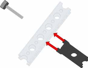

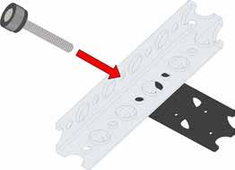


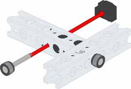
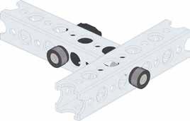
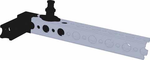
17 End connectors, straight block connectors, and 90-degree cross block connectors are secured using a thumbscrew through the beam and into the connector. 15


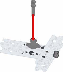

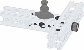

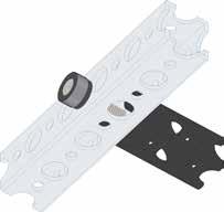
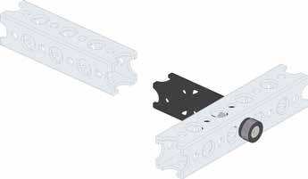
18 After the thumbscrew is used to secure the end of the connector, a quick rivet and peg or a thumbscrew and wing nut are used to secure the intersecting beam. 16


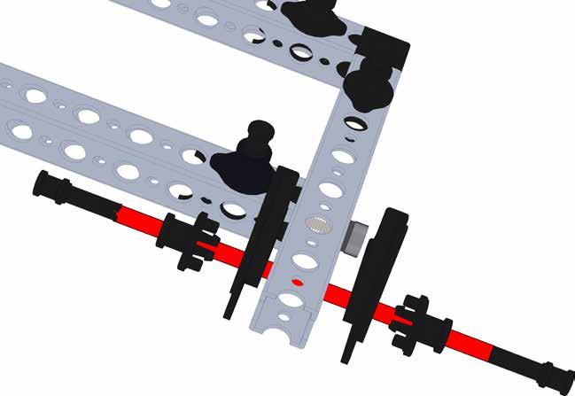
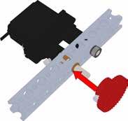
19 Anytime an axle is used, it should be supported at two points. Place a bronze bushing on opposite sides of a beam and place the axle through the bushings. Secure the axle to a stop collar, wheel, gear, or hub. 17
20 18
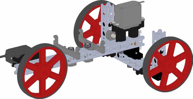
21 Wheelee Bot The Wheelee Bot is a basic three-wheel robot. Two servos are needed: one continuous run servo is used for a drive wheel, and one standard servo provides steering. As an option, a gripper assembly may be added for picking up objects. 19


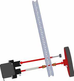
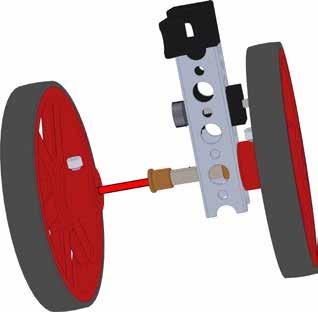
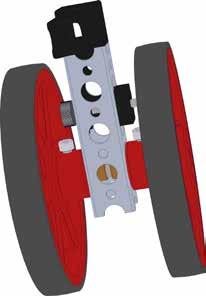
22 Wheelee Bot Assembly Step 1 For this step you will need: Quantity Part 1 15-Hole Beam 1 Wheel & Tire Assembly 1 Continuous Rotation Servo Assembly 2 Setscrew* 1 40 mm Axle 2 Bronze Bushing 1 Thumbscrew 15-Hole Beam Thumbscrew Continuous Rotation Servo 40 mm Axle Setscrew Setscrew Bronze Bushings Wheel & Tire *The setscrew might already be installed in the proper location so another setscrew will not be needed. 20


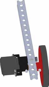

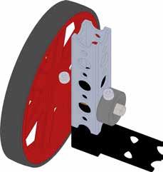
23 Step 1A Step 1B Step 1C 21


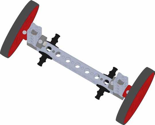
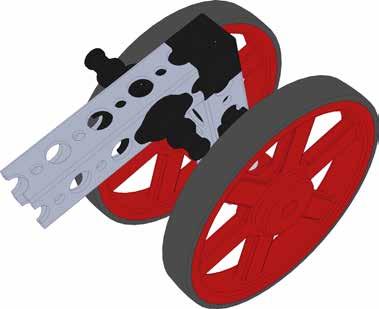
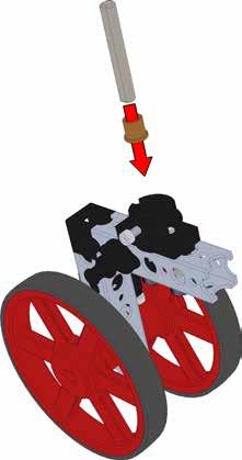
24 Step 2 For this step you will need: Quantity Part 2 Wheel & Tire Assembly 2 4-Hole Beam 2 Shaft Collar 2 40 mm Axle 2 90-Degree Beam Connector 4 Setscrew 4 Bronze Bushing 4-Hole Beam 40 mm Axle Shaft Collar Setscrew Setscrew Bronze Bushings 90-Degree Beam Connector 22


25 Step 2A Step 2B 2X Step 2C Step 2D Step 2E 23
26 Step 3 For this step you will need: Quantity Part 1 8-Hole Beam 4 Quick Rivet Connector 4 Quick Rivet Peg Quick Rivet Peg Quick Rivet Connector 8-Hole Beam Quick Rivet Connector Quick Rivet Peg 24


27 Step 3A Step 3B 25


28 Step 4 For this step you will need: Quantity Part 1 Beam Attachment Hub 2 Thumbscrew 1 40 mm Axle 1 Setscrew 40 mm Axle Beam Attachment Hub Setscrew Thumbscrew 26

29 Step 4A Step 4B 27


30 Step 5 For this step you will need: Quantity Part 1 Standard Servo Motor Assembly 2 Bronze Bushing 1 Setscrew 1 Thumbscrew Standard Servo Motor Assembly Setscrew Bronze Bushing Thumbscrew 28


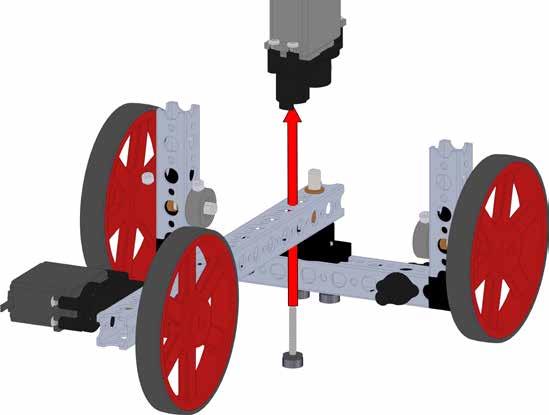

31 Step 5A Step 5B 29


32 Step 5C Step 5D 30
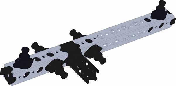
33 Step 6 For this step you will need: Quantity Part 2 Battery Mount Bracket with Bungee Band 2 Wing Nut 2 Thumbscrew Battery Mount Bracket Thumbscrew Wing Nut 31

34 Step 6A Step 6B 32
35 33


36 Making It Move Install the battery using the Bungee Band provided. Connect the continuous run servo motor to Channel 3 of the receiver. Connect the standard servo motor to Channel 1. Connect the battery to the BAT connection. Secure the receiver and wires so they do not become entangled in moving parts. Turn on the remote controller and test the operation of the Wheelee Bot. If the motion does not correspond with the joystick movement, use a screwdriver to change the position of the NOR/REV switches for the appropriate channel. If necessary, use the trimmer controls to stop all movement of the servos when the joystick is in the neutral position. Wheelee Bot Activities After completing the construction of the Wheelee Bot, it is time to have some fun. Practice driving the Wheelee Bot to familiarize yourself with the way it works. Activity 1 Place a piece of masking tape on the floor and set cups upside down to resemble cones. Place the cones in a straight line beginning 24 inches from the tape with 24 inches between each cone. Put another piece of tape on the floor 24 inches past the last cone. Place your Wheelee Bot on the side of the tape opposite the cones. Drive the Wheelee Bot through the cones in a slalom pattern. Use a stopwatch to time how long it takes to drive Wheelee Bot through the slalom course to the tape at the other end of the cones. Try to complete the slalom faster than your partner without hitting the cones. Activity 2 After completing the build of the Wheelee Bot, you can add the optional Gripper Assembly. Refer to the instructions on the following page for attaching the gripper. Assemble the Ball Rack. Refer to the Accessories Section for instructions on how to assemble the Ball Rack. Place four balls on the crossbar of the Ball Rack. Place four small cups about four feet from the Ball Rack. Use the remote controller to maneuver Wheelee Bot into position and pick up a ball using the gripper. Drive the robot to one of the cups and place the ball into the cup. Harvest the remaining balls from the rack and place them in the other cups. Make it a competition by timing how long it takes to move all four balls from the rack to the cups. Activity 3 With permission from your instructor, make modifications to improve the performance of the Wheelee Bot. Some improvement ideas include reducing the turning radius, improving the stability, or improving the steering response. 34


37 Wheelee Bot Gripper Assembly Step 1 Step 2 Step 3 Step 4 Step 5 Step 6 Step 7 Step 8 35
38 36


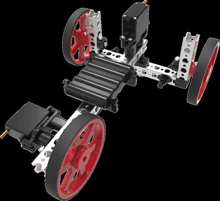
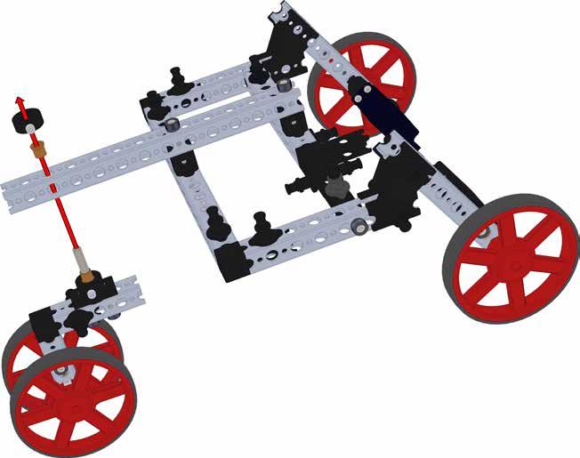
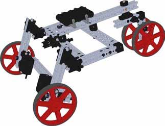
39 Buggee Bot The Buggee Bot is a basic rover-type robot. Two continuous run servos are used for both propulsion and steering. The Buggee Bot can be driven in tank mode or arcade mode. As an option, a gripper assembly utilizing a standard servo may be added for picking up objects from differing heights. 37

40 Buggee Bot Assembly Step 1 For this step you will need: Quantity Part 1 8-Hole Beam 1 4-Hole Beam 1 Tee Beam Connector 2 End Beam Connector 6 Quick Rivet 6 Quick Rivet Peg End Beam Connector End Beam Connector Quick Rivet Peg Quick Rivet 8-Hole Beam Tee Beam Connector 4-Hole Beam Step 1A 38


41 Step 1B Step 1C Step 1D 39
42 Step 2 For this step you will need: 2X Quantity Part 2 7-Hole Beam 2 90-Degree Beam Connector 2 Quick Rivet 2 Quick Rivet Peg Quick Rivet Peg Quick Rivet 90-Degree Beam Connector 7-Hole Beam 40


43 Step 2A Step 2B 41


44 Step 3 For this step you will need: Quantity Part 1 13-Hole Beam 2 Thumbscrew 2 Quick Rivet 2 Quick Rivet Peg Quick Rivet Peg Quick Rivet Thumbscrew 13-Hole Beam Thumbscrew 42


45 Step 3A Step 3B 43


46 Step 4 For this step you will need: Quantity Part 4 60-Degree Bracket 4 Quick Rivet 4 Quick Rivet Peg 60-Degree Bracket Quick Rivet Quick Rivet Peg Step 4A 44


47 Step 4B Step 4C 45


48 Step 5 For this step you will need: 2X Quantity Part 2 Continuous Rotation Servo Assembly 2 Wheel & Tire Assembly 2 40 mm Axle 4 Bronze Bushing 2 8-Hole Beam 2 Thumbscrew 4 Setscrew 4 Quick Rivet 4 Quick Rivet Peg Wheel & Tire Assembly Thumbscrew 8-Hole Beam Continuous Rotation Servo Setscrew Bronze Bushing 46


49 Step 5A Step 5B 47


50 Step 5C Step 5D 48

51 Step 6 For this step you will need: Quantity Part 2 13-Hole Beam 4 Thumbscrew 2 90-Degree Cross Block Connector 4 Quick Rivet 4 Quick Rivet Peg 90-Degree Cross Block Connector 13-Hole Beam Thumbscrew 49


52 Step 6A Step 6B 50


53 Step 6C 51


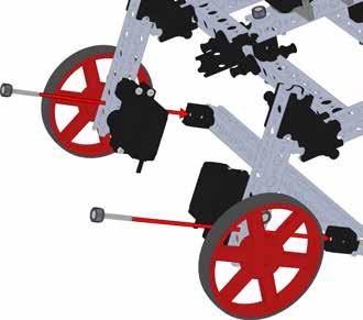
54 Step 7 For this step you will need: 90-Degree Beam Connector Quantity Part 2 4-Hole Beam 1 Thumbscrew 1 Wing Nut 2 Quick Rivet 2 Quick Rivet Peg 1 90-Degree Beam Connector 2 Bronze Bushing 1 40 mm Axle 2 Wheel & Tire Assembly 2 Setscrew Thumbscrew Wing Nut 4-Hole Beam 52


55 Step 7A Step 7B Step 7C 53


56 Step 7D Step 7E 54
57 Step 8 For this step you will need: Quantity Part 1 Beam Attachment Hub 2 Thumbscrew 2 Bronze Bushing 1 40 mm Axle 1 Shaft Set Collar 1 Setscrew 40 mm Axle Bronze Bushing Beam Attachment Hub Thumbscrew 55


58 Step 8A Step 8B Step 8C 56


59 Step 8D 57


60 Step 9 For this step you will need: Quantity Part 2 Battery Mounting Bracket 6 Thumbscrew 2 Wing Nut 1 15-Hole Beam 2 90-Degree Cross Block Connector Thumbscrew Battery Mounting Bracket Wing Nut 58


61 Step 9A Step 9B Step 9C Step 9D Step 9E Step 9F 59
62 Making It Move Install the battery using the Bungee Band provided. Connect the left continuous run servo motor to Channel 1 of the receiver. Connect the right continuous run servo motor to Channel 3. Connect the battery to the BAT connection. Secure the receiver and wires so they do not become entangled in moving parts. Turn on the remote controller and test the operation of the Buggee Bot. If the motion of each servo does not correspond with the joystick movement, use a screwdriver to change the position of the DIP switches. If necessary, use the trimmer controls to stop all movement of the servos when the joysticks are in the neutral position. Buggee Bot Activities After completing the construction of the Buggee Bot, it is time to have some fun. Practice driving the Buggee Bot to familiarize yourself with the way it works. Activity 1 Set the controller to operate in tank mode. Place four cups upside down to resemble cones. Place the cones in a square pattern with 18-inch sides. Place your Buggee Bot in the center of the cones. Drive the Buggee Bot around the cones in a figure-eight pattern. Use a stopwatch to time how long it takes to drive the Buggee Bot through the pattern and back to the center of the cones. Try to complete the figure eight faster than your partner without hitting the cones. Activity 2 Set the controller to operate in arcade mode. Place four cups upside down to resemble cones. Place the cones in a square pattern with 18-inch sides. Place your Buggee Bot in the center of the cones. Drive the Buggee Bot around the cones in a figure-eight pattern. Use a stopwatch to time how long it takes to drive the Buggee Bot through the pattern and back to the center of the cones. Try to complete the figure eight faster than your partner without hitting the cones. Compare the time required to complete the figure eight in each driving mode. Which operating mode allowed you to complete the task faster? Activity 3 After completing the build of the Buggee Bot, you can add the optional Gripper Assembly. Refer to the instructions on the following pages for assembling and attaching the gripper. Invert two small cups to serve as ball supports. Place two small cups about four feet from the two inverted cups. Use the remote control to maneuver the Buggee Bot into position and pick up a ball using the gripper. Drive the robot to one of the cups and place the ball into the cup. Harvest the remaining ball from the support and place it in the other cup. Make it a competition by timing how long it takes to move both balls from the support and place them in the cups. Activity 4 With permission from your instructor, make modifications to improve the performance of the Buggee Bot. Some improvement ideas include reducing the turning radius, improving the stability, or improving the steering response. 60


63 Buggee Bot Moving Gripper Assembly Step 1 Step 2 Step 3 Step 4 Step 5 Step 6 Step 7 Step 8 Step 9 Step 10 61


64 Step 11 Step 12 Step 13 Step 14 Step 15 Step 16 Step 17 62

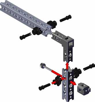
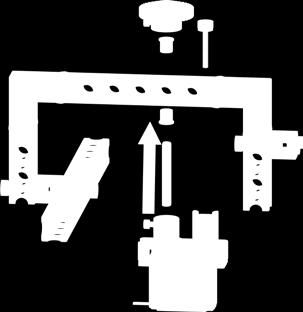
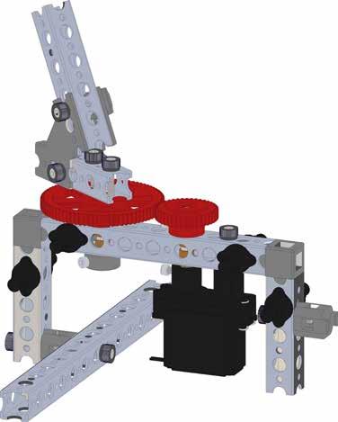
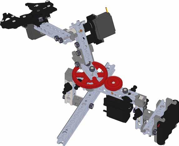
65 Pickee Bot Pickee Bot is a nonmobile pick-and-place robot, similar to an industrial robot that might be used in a manufacturing plant. Three servos are needed: two standard servos to operate and elevate the gripper and one continuous rotation servo to pivot the gripper. 63

66 Pickee Bot Assembly Step 1 For this step you will need: Quantity Part 1 8-Hole Beam 1 4-Hole Beam 1 90-Degree Beam Connector 1 90-Degree Cross Block Connector 1 Thumbscrew 4 Quick Rivet Connector 4 Quick Rivet Peg Quick Rivet Peg 8-Hole Beam Quick Rivet Quick Rivet Quick Rivet Peg 90-Degree Beam Connector Thumbscrew 4-Hole Beam 90-Degree Cross Block Connector 64


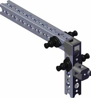

67 Step 1A Step 1B Step 1C Step 1D 65


68 Step 2 For this step you will need: Quantity Part 1 90-Degree Beam Connector 1 4-Hole Beam 1 Thumbscrew 1 90-Degree Cross Block Connector 4 Quick Rivet Connector 4 Quick Rivet Peg 90-Degree Beam Connector Quick Rivet 4-Hole Beam 90-Degree Cross Block Connector Thumbscrew 66


69 Step 2A Step 2B Step 2C 67


70 Step 2D Step 2E 68


71 Step 3 For this step you will need: Quantity Part 1 Thumbscrew 1 13-Hole Beam Thumbscrew 13-Hole Beam Step 3A 69


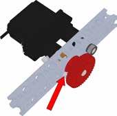
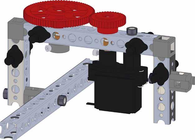
72 Step 4 For this step you will need: Quantity Part 1 40-Tooth Gear 2 Setscrew 2 Bronze Bushing 1 Thumbscrew 1 40 mm Axle 1 Continuous Rotation Servo Assembly 40-Tooth Gear Setscrew Thumbscrew Bronze Bushing 40 mm Axle Continuous Rotation Servo Assembly 70


73 Step 4A Step 4B Step 4C 71

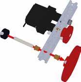
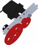
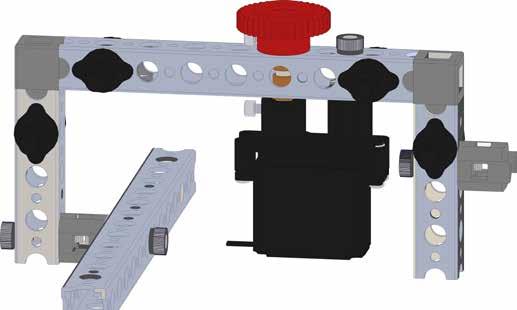
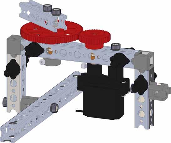
74 Step 5 For this step you will need: Quantity Part 1 80-Tooth Gear 2 Bronze Bushing 1 Thumbscrew 2 Setscrew 1 40 mm Axle 1 Shaft Set Collar 80-Tooth Gear 40 mm Axle Bronze Bushing Shaft Set Collar Setscrew 72


75 Step 5A Step 5B 73
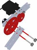
76 Step 6 For this step you will need: Quantity Part 2 Thumbscrew 1 4-Hole Beam Thumbscrew 4-Hole Beam 74


77 Step 6A Step 6B 75


78 Step 7 For this step you will need: Quantity Part 1 5-Hole Beam 2 60-Degree Bracket 2 Thumbscrew 2 Wing Nut 60-Degree Bracket 5-Hole Beam Wing Nut Thumbscrew 76


79 Step 7A Step 7B 77


80 Step 8 For this step you will need: Quantity Part 1 Standard Servo Assembly 1 40 mm Axle 2 Bronze Bushing 1 Thumbscrew 1 Setscrew Bronze Bushing 40 mm Axle Standard Servo Assembly Setscrew Thumbscrew 78


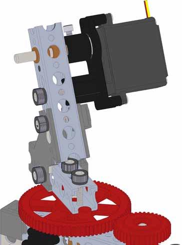

81 Step 8A Step 8B 79


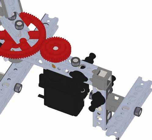
82 Step 9 For this step you will need: Quantity Part 1 8-Hole Beam 2 Thumbscrew 1 Setscrew 1 Beam Attachment Hub Beam Attachment Hub Setscrew 8-Hole Beam Thumbscrew 80


83 Step 9A Step 9B 81

84 Step 10 For this step you will need: Quantity Part 1 Thumbscrew 1 Wing Nut 1 Gripper Assembly Thumbscrew Gripper Assembly Wing Nut 82

85 Step 10A Step 10B 83
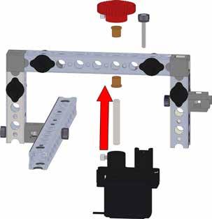
86 Step 11 For this step you will need: Quantity Part 1 5-Hole Beam 3 Thumbscrew 2 Wing Nut 2 Battery Mounting Bracket 5-Hole Beam Thumbscrew 84


87 Step 11A Step 11B 85


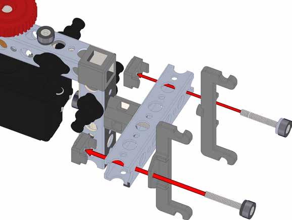

88 Step 11C Wing Nut Thumbscrew Battery Mounting Bracket Step 11D 86


89 Step 11E Step 11F 87
90 Making It Move Install the battery using the Bungee Band provided. Connect the continuous run servo motor to Channel 3 of the receiver. Connect the standard servo motors to Channel 1 and Channel 2. Connect the battery to the BAT connection. Secure the receiver and wires so they do not become entangled in moving parts. Turn on the remote controller and test the operation of the Pickee Bot. If the motion does not correspond with the joystick movement, use a screwdriver to change the position of the DIP switches. If necessary, use the trimmer controls to stop all movement of the servos when the joystick is in the neutral position. Pickee Bot Activities After completing the construction of the Pickee Bot, it is time to have some fun. Practice moving the Pickee Bot and operating the gripper to familiarize yourself with the way it operates. Use caution not to entangle the wires when rotating the gripper boom. Reverse your motion to avoid damaging the wires. Activity 1 Assemble the Ball Rack. Refer to the Accessories Section for instructions on how to assemble the Ball Rack. Place the Ball Rack in a position so that Pickee s gripper is able to reach both ends and the middle holes. Place one cup to the right side of Pickee Bot, one to the left side of Pickee Bot, and one behind Pickee Bot so that Pickee s gripper is able to reach each of the cups. Place a ball on each end of the Ball Rack and one in the middle. Maneuver Pickee s gripper to pick up a ball and place it in one of the cups. Make it a competition to see which partner is able to complete the task in the shortest amount of time. Activity 2 Place an inverted cup in a position in front of the Pickee Bot so that Pickee s gripper is able to reach a ball placed on the cup. Place one cup to the right side of Pickee Bot and one to the left side of Pickee Bot so that Pickee s gripper is able to reach each of the cups. Place a ball on the inverted cup. Maneuver Pickee s gripper to pick up the ball and place it in one of the cups. Place another ball on the support and maneuver Pickee to place this ball in the other cup. Make it a competition to see which partner is able to complete the task in the shortest amount of time. Activity 3 With permission from your instructor, make modifications to improve the performance of the Pickee Bot. Some improvement ideas include eliminating the chance of wire entanglement, increasing the gripper reach distance, improving the stability, or increasing the lifting power. 88

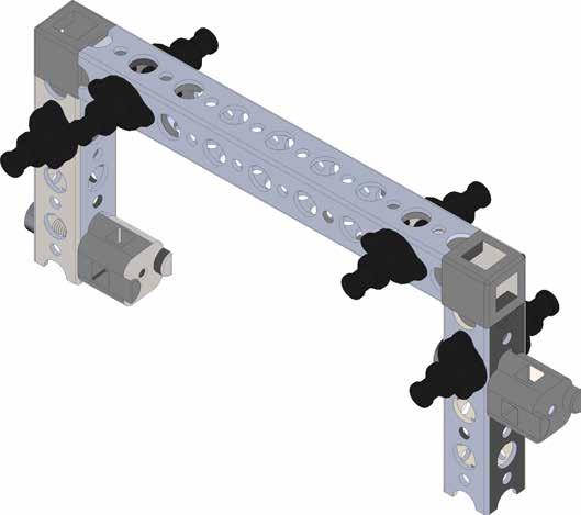
91 Accessories Section Ball Rack Assembly Create this Ball Rack for use with any of the three Bots built using this guide. Step 1 For this step you will need: 2X Quantity Part 2 5-Hole Beam 4 90-Degree Cross Block Connector 2 Thumbscrew Thumbscrew 8-Hole Beam 90-Degree Cross Block Connector 89

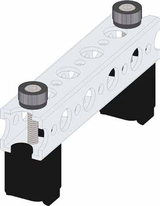

92 Step 1A Step 1B 90

93 Step 2 For this step you will need: Quantity Part 2 Thumbscrew 2 90-Degree Cross Block Connector 90-Degree Cross Block Connector Thumbscrew 91

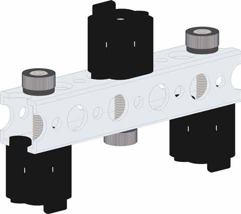

94 Step 2A Step 2B 92
95 Step 3 For this step you will need: Quantity Part 1 15-Hole Beam 2 Thumbscrew Thumbscrew 15-Hole Beam 93

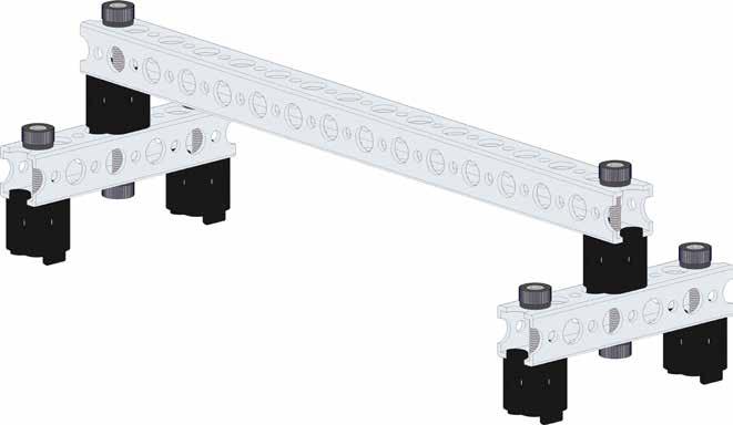

96 Step 3A Step 3B 94
97 95


98 Builder s Guide Call Toll-Free FreeFax Visit Us Online at shop.pitsco.com
HANG GLIDER (RECHARGEABLE)
") HANG GLIDER (RECHARGEABLE) 91192 ASSEMBLY AND OPERATING INSTRUCTIONS 3491 Mission Oaks Blvd., Camarillo, CA 93011 Visit our Web site at http://www.harborfreight.com IMPORTANT: If damage is caused due to
HANG GLIDER (RECHARGEABLE) 91192 ASSEMBLY AND OPERATING INSTRUCTIONS 3491 Mission Oaks Blvd., Camarillo, CA 93011 Visit our Web site at http://www.harborfreight.com IMPORTANT: If damage is caused due to
Wireless Wind Sensor Installation and Operation Instructions
 WARNINGS: RETRACTABLE AWNINGS For Technical Support visit us at www.sunsetter.com/ownerscorner or Call Toll Free 800-670-7071 Fax 877-224-4944 Wireless Wind Sensor Installation and Operation Instructions
Solera Power Awning OEM INSTALLATION MANUAL
 Solera Power Awning OEM INSTALLATION MANUAL TABLE OF CONTENTS System Information 2 Safety 2 Prior To Installation 2 Resources Required 2 Awning Rail Installation (If Needed) 3 Installation 3 Awning Installation
MYRIAD Banner Stand is a trademark of Skyline Exhibits. Patent Pending PN32294-B. MYRIAD Banner Stand
 is a trademark of Skyline Exhibits Patent Pending 1.1 1. Banner Stand Setup 1.1 Remove banner stand from standard case or Arrive Portable Display & Workstation and assemble pole. 1.2 Insert pole into base
quick and easy installation guide
 www.directdriveopener.com quick and easy installation guide Back 2 Front. Motor Carriage 2. C-rail. Chain. Limit stops. Slide in part (tensioner) Rail assembly Insert C-rail parts () into the connecting
READ ME! IMPORTANT WARNING! ENG. Quick Release Tent Mount Kit
 Quick Release Tent Mount Kit ENG TBMK008 READ ME! Thank you for purchasing a Front Runner Quick Release Tent Mount Kit. Before you start, take a moment to familiarize yourself with the Fitting Instructions
SPIRAL SLICER Instruction Manual Model #5280 & 5280M. Part No Revised Feb. 2010
 SPIRAL SLICER Instruction Manual Model #5280 & 5280M Part No. 82876 Revised Feb. 2010 SAFETY PRECAUTIONS INSTALLATION INSTRUCTIONS Inspection of Shipment: 5280 & 5280M SPIRAL SLICER Unpack all cartons
AWNING CONTROL KIT 98GCK-33B
 AWNING CONTROL KIT 98GCK-33B REV.07282015 RV AWNING PRODUCTS 1361 CALLE AVANZADO, SAN CLEMENTE, CA 92673 (800) 382-8442 FAX (949)276-5500 www.girardrv.com AC MOTOR CONTROL MODULE GC274B INSTALLATION and
NEWMAR SERVICE SCHOOL
 NEWMAR SERVICE SCHOOL TRAINING INFORMATION GUIDELINE FOR FEBRUARY 2013 OUR PRODUCTS: NOVA DUAL PITCH AWNING G-2000/ G-1500 2 P a g e G-2085 G-5000 3 P a g e G-LINKS 4 P a g e NOVA/ G-2000/ G-1500 BASIC
front runner READ ME! IMPORTANT WARNING! ENG Foxwing Awning Brackets
 front runner Foxwing Awning Brackets ENG RRAC0 READ ME! Thank you for purchasing Front Runner Foxwing Awning Brackets. Before you start, take a moment to familiarize yourself with the Fitting Instructions
INSTRUCTION MANUAL ALEKO RETRACTABLE AWNING
 INSTRUCTION MANUAL for ALEKO RETRACTABLE AWNING www.alekoproducts.com FAILURE TO FOLLOW THESE INSTRUCTIONS MAY RESULT IN PERSONAL INJURY! 1 Important Safety Precautions WARNING NOTE: FOR PERSONAL SAFETY,
INSTRUCTION SHEET DETHATCHER KIT. STS-422LX LPSTS-42JD Assembly Installation Operation Repair Parts L-1660-D. Visit us on the web!
 INSTRUCTION SHEET DETHATCHER KIT MODEL: DK-422LX FOR USE WITH SWEEPER MODEL: STS-422LX LPSTS-42JD Assembly Installation Operation Repair Parts For use with Riders and Lawn/Garden Tractors For the latest
ALEKO Victoria Series Retractable Awning Instructions for Installation and Operation
 www.alekoproducts.com ALEKO Victoria Series Retractable Awning Instructions for Installation and Operation PLEASE DO NOT RETURN THIS PRODUCT TO THE STORE! The owner s manual includes assembly and operating
READ ME FIRST! IMPORTANT WARNING! ENG. Roof top tent
 Roof top tent ENG TENT031 220 min READ ME FIRST! Thank you for purchasing a Front Runner Roof Top Tent. Before you start, take a moment to familiarize yourself with these Fitting Instructions and the components
Phantom Retractor System Overview
 Spine Phantom Retractor System Overview Minimally invasive procedures Dual-directional expandable retractor 30 degree pivoting blades Fiber-optic light source for better visualization Key Design Features
Antenna Tower Positioning System
 Model 1052 Antenna Tower Positioning System User Manual (Antenna not included) ETS-Lindgren L.P. reserves the right to make changes to any product described herein in order to improve function, design,
HANDLE AND WHEEL KIT INSTALLATION
 HANDLE AND WHEEL KIT INSTALLATION Select EB and EM Series Generators Honda Power Equipment Your generator is equipped with a wheel kit and folding handle kit for easy transport and convenient storage.
t420 Barbecue Assembly Manual
 t20 Barbecue Assembly Manual 85-300-2 (G510) Propane 85-3005-0 (G5105) Natural Gas 1 Year limited Warranty Read and save manual for future reference. If pre-assembled, leave this manual with unit for consumer
FROM CONCEPT TO DESIGN
 Shieldy Bot - From Concept to Design Roak Ely, Mark Cieslikowski, Mekai Ely Lincoln BCBs Team 07-0047 Coach: Linda Reynolds teckteacher@yahoo.com Shieldy Bot FROM CONCEPT TO DESIGN Figure 1 Shieldy Bot
User s Manual Trampoline 8
 User s Manual Trampoline 8 Model! WARNING Read all precautions and instructions in this manual before using this equipment. Save this manual for future reference. Maximum user weight 17 lbs. ASSEMBLY IMPORTANT
Instruction for edge trimming knife sharpening of M-Type shoe sewing machines
 Instruction for edge trimming knife sharpening of M-Type shoe sewing machines 1. Introduction This instruction is a supplement to the instruction for use of electric table sharpener; thus the scope of
EEZI - AWN series 1000 / 2000 Awning bracket
 EEZI - AWN series 1000 / 2000 Awning bracket RRAC063 INSTALL TIME: 15 mins IMPORTANT WARNING! IT IS CRITICAL THAT ALL FRONT RUNNER PRODUCTS BE PROPERLY AND SECURELY ASSEMBLED AND ATTACHED TO YOUR VEHICLE.
Motorized Cassette Awning E6100. Instruction ROHS
 Motorized Cassette Awning E6100 Instruction ROHS 1 Installation Instruction for E6100 Cassette Awning I. Installation Steps of E6100 Cassette Awning.2 II. Installation Guide of DLC-B Controlling board
PARTS LIST eforce Burnisher
 PARTS LIST eforce Burnisher HEAD ASSEMBLY ITEM PART NO. DESCRIPTION QTY 101 6496721 MOTOR 36 VOLT, 2100 RPM, 3.6HP [see pages 16,17] 1 102 9121410 5/16 EXTERNAL STAR LOCK WASHER PACK OF 10 2 103 6492051
Auxiliary 63.5l Fuel Tank Ford/Mazda Pick-up Truck 2012-Current READ ME! IMPORTANT WARNING!
 Auxiliary 63.5l Fuel Tank Ford/Mazda Pick-up Truck 2012-Current ENG FTFM006 90 min READ ME! Thank you for purchasing a Front Runner Ford/Mazda Pick-Up Truck 2012 - Current Fuel Tank. Before you start,
INSTALLATION INSTRUCTIONS TOWNSEND
 INSTALLATION INSTRUCTIONS TOWNSEND.00 DECK MOUNT BATH FILLER.0 Thank you for selecting American Standard... the benchmark of fine quality for over 00 years. To ensure that your installation proceeds smoothly-please
Thomas Scientific Swedesboro, NJ U.S.A.
 Thomas Scientific Swedesboro, NJ 08085-0099 U.S.A. Wiley Laboratory Mill, Model 4 3375-E10 (115 V, 50/60 HZ) USE AND CARE OF CATALOG NUMBER: 3375-E10 Wiley Laboratory Mill, Model 4 (115 V, 50/60 HZ) UNPACKING
12V MOTION SENSOR 98GC779G INSTALLATION & PROGRAMMING GUIDE REV RV AWNING PRODUCTS
 12V MOTION SENSOR 98GC779G INSTALLATION & PROGRAMMING GUIDE REV.07242015 RV AWNING PRODUCTS 1361 CALLE AVANZADO, SAN CLEMENTE, CA 92673 (800) 382-8442 FAX (949)276-5500 www.girardrv.com Girard Systems
AUTO REWIND HOSE REEL WITH 50 FOOT HOSE. Model 46320
 AUTO REWIND HOSE REEL WITH 50 FOOT HOSE Model 46320 ASSEMBLY AND OPERATING INSTRUCTIONS 3491 Mission Oaks Blvd., Camarillo, CA 93011 Visit our Web site at http://www.harborfreight.com Copyright 2001 by
80070 TOP MOUNT CAMPER SHELL and TRANSIT CONNECT RACK TMCS_3:1
 ASSEMBLY INSTRUCTIONS for : 80070 TOP MOUNT CAMPER SHELL and TRANSIT CONNECT RACK TMCS_3:1 (916) 638-8703 (800) 343-7486 11261 Trade Center Drive Rancho Cordova, CA 95742 www.kargomaster.com Transit ASSEMBLY
Assembly TOOLS REQUIRED: 17mm and 14mm or equivalent wrenches.
 Instructions for 3 Trimmer Rack, 3TR* *Patents Pending Assembly TOOLS REQUIRED: 17mm and mm or equivalent wrenches. 15 26 26 16 15 16 Attach the lower mounting brackets to the Trimmer Rack poles as shown
300 ft. 5/8 Hose wagon
 300 ft. 5/8 Hose wagon Model 95956 Assembly And Operation Instructions Due to continuing improvements, actual product may differ slightly from the product described herein. (Garden hose is not included).
PLATINUM MODEL WITH AUTO-RETRACT AND REMOTE CONTROL. Owner s Manual
 PLATINUM MODEL WITH AUTO-RETRACT AND REMOTE CONTROL Owner s Manual THIS MANUAL CONTAINS INSTRUCTIONS FOR UPGRADING BOTH THE GOLD MODEL ONE-TOUCH AND THE ONE-TOUCH MODEL WITH THE KEY SWITCH TO THE PLATINUM
Roller Bar End Cap (w/round Drive Shaft) Replacement Instructions for Vista and Motorized Awnings * Helpers needed *
 Replacement Instructions for Vista and Motorized Awnings * Helpers needed *") RETRACTABLE AWNINGS For Technical Support visit us at www.sunsetter.com/ownerscorner or Call Toll Free 800-670-7071 Fax 877-224-4944 Roller Bar End Cap (w/round Drive Shaft) Replacement Instructions for
RETRACTABLE AWNINGS For Technical Support visit us at www.sunsetter.com/ownerscorner or Call Toll Free 800-670-7071 Fax 877-224-4944 Roller Bar End Cap (w/round Drive Shaft) Replacement Instructions for
Product instruction manual Ream Cutting Systems RE3943, RE3946, RE3947, RE3971, RE3952E
 Product instruction manual Ream Cutting Systems RE3943, RE3946, RE3947, RE3971, RE3952E The Trimfast Ream Cutters are reliable, high performance cutters that will give you the results you need quickly
ASSEMBLY GUIDE. Customer Service: INCH² 3-BURNER & 545 INCH² 3-BURNER
 ASSEMBLY GUIDE 455 INCH² 3-BURNER & 545 INCH² 3-BURNER DANGER If you smell gas: 1. Shut off gas to the appliance. 2. Extinguish any open flames. 3. Open lid. 4. If odor continues, keep away from the appliance
ABS Model Background Stand
 ABS Model Background Stand Product Overview: The completely redesigned Ravelli ABS model background stand is 10' tall by 12.3' wide. It is comprised of two tripod stands and four 3 cross bar sections and
INSTALLATION INSTRUCTIONS AND OWNER'S MANUAL AWNINGS. For trailers & motor homes with straight sides TOOLS REQUIRED
 AWNINGS INSTALLATION INSTRUCTIONS AND OWNER'S MANUAL For trailers & motor homes with straight sides TOOLS REQUIRED 1/4" electric drill Ratchet handle kit 3/8" & 7/16" socket No. 1 and No. 2 screwdriver
Important! Read all of these instructions before assembling or riding the glider. For questions or help please call Glide Bikes at
 Go Glider Manual Congratulations on your purchase of the Go Glider! Your glider is designed for years of nearly carefree use by your child. These instructions include how to set up your glider and maintenance
Assembly. Step 3. Attach the safety bracket (7) to the Pivot ARM (6).
 to the Pivot ARM (6).") Assembly Step 1. A. Stand the base of the machine by separating the U-frames (1,2). Pull the Front and Rear U-Frames (1,2) as far apart from each other as possible. Then push down on the middle of the
Assembly Step 1. A. Stand the base of the machine by separating the U-frames (1,2). Pull the Front and Rear U-Frames (1,2) as far apart from each other as possible. Then push down on the middle of the
PARTS LIST COLT COLT HEPA
 PARTS LIST COLT 800-1250 - 1450 COLT HEPA - 1250-1450 MOTOR / LID ITEM PART NO. PART DESCRIPTION QTY. 101 0891201 TOP COVER 1 102 0294341 TOP MOTOR SEAL 1 103 0299861 STRAIN RELIEF CORD CLAMP 1 104 0891131
300 Model 870 Four Wheel Hose Cart Owner s Manual
 300 Model 870 Four Wheel Hose Cart Owner s Manual IMPORTANT: READ THE OWNER S MANUAL BEFORE ASSEMBLING TOOLS REQUIRED: TWO ADJUSTABLE WRENCHES; HAND PUMP Estimated assembly time: 30 minutes PARTS LIST
S405 Barbecue Assembly Manual
 S405 arbecue ssembly Manual 85-02-6 (G4705) Propane Year limited Warranty Read and save manual for future reference. If pre-assembled, leave this manual with unit for consumer s future reference. For product
Model 698/ and Model in 1 Hose Reel Owner s Manual
 Model 698/694 200 and Model 706 100 4 in 1 Hose Reel Owner s Manual 698/694 706 VISIT OUR WEBSITE: WWW.LIBERTYGARDENPRODUCTS.COM OR CALL US TOLL FREE AT 1-866-820-5805 LIBERTY GARDEN PRODUCTS, INC. 500
PARTS LIST CHARGER 2022 ABLT
 PARTS LIST CHARGER 2022 ABLT HEAD ASSEMBLY ITEM PART NO. DESCRIPTION QTY 101 5990731 SPRING CLIP PAD HOLDER SET INCLUDES: 1 101A 9120205 #8 X 1/2 PAN HEAD PHILLIPS SHEET METAL SCREW PACK OF 3 3 102 9121490
SKYTRAK REAL GAME REAL RESULTS. Quick Start Guide
 SKYTRAK REAL GAME REAL RESULTS Quick Start Guide IMPORTANT: Read carefully the SkyTrak Safety and Product Information Guide before setup or use of the SkyTrak TM system. Failure to read and follow the
ASSEMBLY INSTRUCTIONS
 ASSEMBLY INSTRUCTIONS NT-MG1158 58" Glass and Metal TV Stand Safety information and specifications...2 Tools needed...3 Parts...3 Hardware...4 Assembly instructions...5 Safety information and specifications
PLATINUM MODEL WITH AUTO-RETRACT AND REMOTE CONTROL. Owner s Manual
 PLATINUM MODEL WITH AUTO-RETRACT AND REMOTE CONTROL Owner s Manual THIS MANUAL CONTAINS INSTRUCTIONS FOR UPGRADING BOTH THE GOLD MODEL ONE-TOUCH AND THE ONE-TOUCH MODEL WITH THE KEY SWITCH TO THE PLATINUM
Blue Series Hot Melt Hose with RediFlext II Hanger System
 Instruction Sheet P/N 1124594_01 Blue Series Hot Melt Hose with RediFlext II Hanger System Safety WARNING! Allow only personnel with appropriate training and experience to operate or service the equipment.
Alternative Designs Report Joshua s Jumper
 Alternative Designs Report Joshua s Jumper By Elyssa Polomski, Michael Ballintyn, and Tianyi Xu Team # 21 Client: Joshua Bouchard Client Contact: Sue and Ron Bouchard, soupanony@aol.com, (508) 823-6113
Rhino-Rack SUNSEEKER Awning Black
 Rhino-Rack SUNSEEKER Awning Black 1. Check Part No./Kit is correct 3. Fit roof rack accessory 2. Read through instruction before installing 4. Check and recheck all fasteners are secure Layout 2.0m - 32132
Installation Instructions
 THE COLLECTION by Installation Instructions 0 BIDET FITTING Thank you for selecting American-Standard...the benchmark of fine quality for over 00 years. To ensure that your installation proceeds smoothly--please
Wenger Corporation 2014 Printed in USA 05/14 Part #049B015-09
 Assembly Instructions Tuba Tamer Contents Important User Information...........................2 Replacemant Parts List..............................3 Assembly.........................................4
Add 3-AA Batteries BASEBALL PEG
 MLB Series Bat, Baseball, and Glove Pegs The MLB Series Laser Pegs kit includes the Bat, Baseball, and Glove Pegs. These shapes can be used with any other existing Laser Pegs kit. All three of the MLB
DO NOT USE WITH CROSSBAR SPREAD LESS THAN 24.
 TM Please read all instructions carefully before assembly, installation and/or use of this product. DO NOT USE WITH CROSSBAR SPREAD LESS THAN 24. WARNING: Do not exceed the weight limit of your vehicle
BR-2250/BR Burnisher. Operator and Parts Manual. Model No.: BR BR-2250 Can. Pac BR BR-2500 Can.
 BR-220/BR-200 Burnisher Model No.: 608342 BR-220 609248 BR-220 Can. Pac 608340 BR-200 609247 BR-200 Can. Pac Operator and Parts Manual NOBLES 1287 RANSOM STREET HOLLAND MI 49424 U.S.A. CUSTOMER SERVICE:
CHANGING YOUR LANDSCAPE SINCE 1945 OWNER S MANUAL. Tow Hitch Replacement Kit For Rough Cut Trailcutters. Starting Serial # L
 CHANGING YOUR LANDSCAPE SINCE 1945 OWNER S MANUAL Tow Hitch Replacement Kit For Rough Cut Trailcutters 21100 Starting Serial # L118-023001 Tools Required: Wrench/Socket Qty. Size (1) 1-1/8 (1) 1-1/16 (2)
All of these configurations are from one 2005 Blue Ultralite Trayman. Just slide the straps up and over your shoulders and they will slip into place.
 All of these configurations are from one 2005 Blue Ultralite Trayman. Just slide the straps up and over your shoulders and they will slip into place. The back edge of the Shoulder Strap has a slight bend
S420 Barbecue Assembly Manual
 TM MC S420 Barbecue Assembly Manual 85-3062-2 (G45123) Propane 85-3063-0 (G45124) Natural Gas 1 YEAR LIMITED WARRANTY READ AND SAVE MANUAL FOR FUTURE REFERENCE. Assemble your grill immediately. Missing
R/C Proficiency Programme
 R/C Proficiency Programme The Wings Programme for basic R/C Flight qualification. From 1 September 2006 it will be compulsory for all members to have a Wings Badge qualification or when flying be under
Installation Instructions for the Rolltec Bravo Awning
 Installation Instructions for the Rolltec Bravo Awning Questions? Call Rolltec at 1-800-667-0474 Table of Contents Available installation brackets Side dimensions of various installations Determining installation
Assembly and Installation Instructions
 U.S. patent number 8,708,369 part number 4750 for Blue Ox tow bars with Blue Ox brackets, Demco tow bars with Demco brackets, and all motorhome-mounted ROADMASTER tow bars Assembly and Installation Instructions
1946 READ AND SAVE THESE INSTRUCTIONS!
 EasyAwn Installation, Care and Maintenance Manual EasyAwn Quality, Since 1946 EasyAwn, LLC Toll Free: 877-EasyAwn http://www.easyawn.com READ AND SAVE THESE INSTRUCTIONS! EasyAwn Quarter Round Awning Installation
Lab Skills: Introduction to the Air Track
 Lab Skills: Introduction to the Air Track 1 What is an air track? An air track is an experimental apparatus that allows the study of motion with minimal interference by frictional forces. It consist of
* * KR54-F, KR9854 & KR9954 Installation Instructions. Read All Warnings Before Starting Installation! Index:
 *941061-00* 941061-00 Keyed Removable Mullion KR54-F, KR9854 & KR9954 Installation Instructions CLASSIFIED CLASSIFIED C Read All Warnings Before Starting Installation! Index: General Information ----------------
Deep Cleaning a Passap is a three step process: Tear down, Clean, and Reassemble.
 kni!sings Deep Clean A Passap Duomatic Deep Cleaning a Passap is a three step process: Tear down, Clean, and Reassemble. I won t mislead you. Your nerves will be on edge while you take apart your precious
Kontrol Kube Advanced Owners Manual
 Mobile Containment. Simplified. TM Kontrol Kube Advanced Owners Manual KONTROL KUBE www.kontrolkube.com 800.343755 1 IMPORTANT SAFETY INFORMATION SAVE THESE INSTRUCTIONS. CAREFULLY READ AND FOLLOW THESE
Solera Power Awning w/ LED Lights OEM INSTALLATION MANUAL
 Solera Power wning w/ LED Lights OEM INSTLLTION MNUL TBLE OF CONTENTS Safety 2 Prior to Installation 2 Resources Required 2 wning Installation 3 wning Rail Installation (If Needed) 3 wning Support rm Installation
Installation and User s Manual 12 x 10 MOTORIZED AWNING
 12 x 10 MOTORIZED AWNING Installation and User s Manual 12 x 10 MOTORIZED AWNING 088-1763-0 Stop Please read and understand this manual before any assembly or use of this product. Before beginning assembly
Installation Instructions for the Rolltec Adalia X3M Extenda Awning
 Installation Instructions for the Rolltec Adalia X3M Extenda Awning Questions? Call Rolltec at 1-800-667-0474 General Tool Requirements Table of Contents Available installation brackets Side dimensions
Gas Go Anywhere /23/01
 Gas Go Anywhere 55014 02/23/01 FOR OUTDOOR USE ONLY This grill does not include an LP fuel tank. Check Package Contents You should have received the parts listed below. While we give much attention to
PARTS BOOK CATALOG SIDE HD FLAIL HEADS TRACTOR MID-MOUNT
 PARTS BOOK CATALOG SIDE HD FLAIL HEADS TRACTOR MID-MOUNT DIAMOND MOWERS, Inc. 350 E 60 th St. North Sioux Falls, SD 57104 FOR WARRANTY CALL DIAMOND MOWERS DIRECT: 888-960-0364 OUR TECHNICIANS WILL DIAGNOSE
PRODUCT INFORMATION MANUAL SECTION: 17 METAL LOUVRE AWNINGS METAL LOUVRE AWNINGS
 METAL LOUVRE AWNINGS Sizes & Limitations Metal Louvre Awnings TRINIDAD TRINIDAD SUNGUARD FIXED ADJUSTABLE Maximum Width Unlimited 5000mm Unlimited Minimum Width 500mm 500mm 500mm Maximum Drop 4000mm 2500mm
Installation Instructions for the Rolltec Physique XL Awning
 Installation Instructions for the Rolltec Physique XL Awning Questions? Call Rolltec at 1-800-667-0474 General Tool Requirements Table of Contents Available installation brackets Side dimensions of various
Solera Power Awning. Resources Required. Installation and Owner s Manual (For Aftermarket Application)
") Solera Power Awning Solera Power Awning Installation and Owner s Manual (For Aftermarket Applications) Table of Contents Troubleshooting Manual Override Solera Power Awning Troubleshooting Solera Power
Solera Power Awning Solera Power Awning Installation and Owner s Manual (For Aftermarket Applications) Table of Contents Troubleshooting Manual Override Solera Power Awning Troubleshooting Solera Power
--- BIG LEAGUE BATTING CAGE ---
 --- BIG LEAGUE BATTING CAGE --- BGLC-7500 Call Jaypro Sports Equipment at 1-800-243-0533 during regular business hours for technical support. www.jaypro.com Rev-B Page 1 of 22 IMPORTANT NOTICE: 1. BEFORE
TECHNICAL BULLETIN TRI-FUNCTIONAL BUSH INSPECTION
 TECHNICAL BULLETIN TRI-FUNCTIONAL BUSH INSPECTION LIT NO: 97117-135 DATE: June 2018 REVISION: E 6 Inch Bush 3 Inch Bush The TRI-FUNCTIONAL Bush (TFB ) is a key factor in both ride quality and roll stability
Otter Pro X-Over Lodge Installation and Set-Up Instructions
 Otter Pro X-Over Lodge Installation and Set-Up Instructions Otter Pro X-Over Lodge Fits Magnum Otter II & Pro Sled Only Parts Identification and Check List MODEL NUMBERS: Complete Pkg Pro X-Over Lodge
EXCEL MODULAR FOLDING SIDE BRACKET
 EXCEL MODULAR FOLDING SIDE BRACKET Excel folding side brackets are designed to provide scaffold deck extensions out to six (6) feet. They are also designed to fold up, so that they can be used inside vessels
Sunea screen io EN ES PT EL Installation guide Guía de instalación Guia de instalação Ref C
 www.somfy.com Sunea screen io Ref. 506559C ES PT EL Installation guide Guía de instalación Guia de instalação CONTTS. Introduction. Safety.. Safety and responsibility. Installation.. Mot preparation..
GT370 HEDGETRIMMER TYPE
 GT370 HEDGETRIMMER TYPE 1 Introduction Exploded Drawing Bill Of Material Repair Instructions E13791 GT370-----A New Parts Wiring Diagram Main Menu 44 18 02-04 SEAN HOLDEN GT370 MANUFACTURING PLANT USTI
SOLHARO ASSEMBLY & INSTALLATION INSTRUCT IONS
 A. Introduction: SOLHARO ASSEMBLY & INSTALLATION INSTRUCT IONS Rev. 01/30/2012 The Solharo is an external, retractable, tensioned sun shading system designed to fit over a sunroom or wood pergola. The
ASSEMBLY GUIDE. Customer Service: INCH² 2-BURNER & 864 INCH² 2-BURNER
 ASSEMBLY GUIDE 688 INCH² 2-BURNER & 864 INCH² 2-BURNER DANGER If you smell gas: 1. Shut off gas to the appliance. 2. Extinguish any open flames. 3. Open lid. 4. If odor continues, keep away from the appliance
accidents which arise due to non-observance of these instructions and the safety information herein. CAUTION:
 AUTO REWIND HOSE REEL Model: 7640 CALIFORNIA PROPOSITION 65 WARNING: You can create dust when you cut, sand, drill or grind materials such as wood, paint, metal, concrete, cement, or other masonry. This
How to Build Your Own Flour Mill and Sifter
 Prototype and plans developed by Hugo Gervais Custom Fabrication, North Hero, VT Materials List: How to Build Your Own Flour Mill and Sifter Quantity Materials 4 2 X 2 X 26 3 / 16 Square tubing 1 2 X 2
ASSEMBLY INSTRUCTIONS
 ASSEMBLY INSTRUCTIONS NT-MG302FMS 56" TV Stand Safety information and specifications...2 Tools needed...3 Parts...3 Hardware...4 Assembly instructions...5 Safety information and specifications CAUTION:
READ AND SAVE THESE INSTRUCTIONS! EasyAwn Spear Awning Installation
 EasyAwn Installation, Care and Maintenance Manual EasyAwn Quality, Since 1946 EasyAwn, LLC Toll Free: 877-EasyAwn http://www.easyawn.com READ AND SAVE THESE INSTRUCTIONS! EasyAwn Spear Awning Installation
Primrose Awnings - Full Cassette Manual & Electric Instructions
 Primrose Awnings - Full Cassette Manual & Electric Instructions Contents Warning 2.0m - 3.5m Awnings 8 x Expansion bolts ** 2 x brackets 1 x Awning 1 x Winder 4.0m - 5.0m Awnings 12 x Expansion bolts **
Cabinet Mount Assist Lift n Lock Instructions
 Cabinet Mount Assist Lift n Lock Instructions PART LIST 2 @ Gas Cylinder 1 @ Lock Bar 2 @ Rubber Sleeve (preset) 4 @ Stopper Pin (2pcs preset) 4 @ Saddle Block 8 @ 19mm Black PVC Cap 5 @ 14mm Black PVC
Installation and Maintenance Manual
 Freestanding Gas Stove MODEL: PGS2005 GPEBB20R GPEBW20R Installation and Maintenance Manual Warning Maintenance products should be carried out by professional and technical personnel with relevant qualification,
READ AND SAVE THESE INSTRUCTIONS! EasyAwn Standard Awning Installation
 EasyAwn Installation, Care and Maintenance Manual EasyAwn Quality, Since 1946 EasyAwn, LLC Toll Free: 877-EasyAwn http://www.easyawn.com READ AND SAVE THESE INSTRUCTIONS! EasyAwn Standard Awning Installation
READ AND SAVE THESE INSTRUCTIONS! EasyAwn Dome Awning Installation
 EasyAwn Installation, Care and Maintenance Manual EasyAwn Quality, Since 1946 EasyAwn, LLC 3575 Trotters Drive, Bldg A Alpharetta, GA 30004 Toll Free: 877-EasyAwn http://www.easyawn.com READ AND SAVE THESE
RAFTER VI. Installation and Operation CAREFREE WITH AUTOMATIC AWNING SUPPORT. RV Accessory PRODUCT OVERVIEW
 CAREFREE RAFTER VI RV Accessory WITH AUTOMATIC AWNING SUPPORT Installation and Operation PRODUCT OVERVIEW The gives the awning user the ability to easily tighten the center fabric when the awning is extended.
33100 LH - Batwing Awning RH - Batwing Awning
 33100 LH - Batwing Awning 33200 RH - Batwing Awning 1. Check Part No./Kit is correct 3. Fit roof rack accessory 2. Read through instruction before installing 4. Check and recheck all fasteners are secure
Colonial and Grand Colonial Fire Pit Tables. Installation Instructions for
 Colonial and Grand Colonial Fire Pit Tables Installation Instructions for Colonial-48-M-K, Col-48-MNB-K, Grand-Colonial-48-K, CM-48-DIN-K, MNB-48-DIN-K, GC-48-DIN-K, CM-48-PUB-K, MNB-48-PUB-K, GC-48-PUB-K
DIAMOND TECH INTERNATIONAL Innovations For Creativity DIAMOND LASER BAND SAW OPERATIONS MANUAL
 SPEEDSTER-XL INSTRUCTION MANUAL DIAMOND TECH INTERNATIONAL Innovations For Creativity SPEEDSTER-XL DIAMOND LASER BAND SAW OPERATIONS MANUAL SPEEDSTER-XL INSTRUCTION MANUAL - PAGE 1 Before You Begin Read
Fat biplane. Project from
 Project: Fat Biplane Page 1 of 23 Fat biplane Playing games is an integral part of every person s life. The game is very important for growing up the child, because children fully concentrate to it, they
STOP BOX SCRAPER/GRADER BLADE. Owner's Manual. Model No Safety Assembly Operation Maintenance Parts
 Owner's Manual STOP BOX SCRAPER/GRADER BLADE Model No. 486.242411 DO NOT RETURN TO STORE For Missing Parts or Assembly Questions Call 1-866-576-8388 CAUTION: Before using this product, read this manual
BASEBALL PEG. Remove the three Philips head screws with a 4mm screw driver. Requires (3AA) Batteries
 Batteries") MLB Series Bat, Baseball, and Glove Pegs The MLB Series Laser Pegs kit includes the Bat, Baseball, and Glove Pegs. These shapes can be used with any other existing Laser Pegs kit. All three of the MLB
MLB Series Bat, Baseball, and Glove Pegs The MLB Series Laser Pegs kit includes the Bat, Baseball, and Glove Pegs. These shapes can be used with any other existing Laser Pegs kit. All three of the MLB
Motorized retractable awning
 Motorized retractable awning Model 95295 Set up And Operating Instructions Diagrams within this manual may not be drawn proportionally. Due to continuing improvements, actual product may differ slightly