Albatros/Albatros Plus
|
|
|
- Kevin Henry
- 6 years ago
- Views:
Transcription
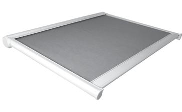
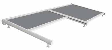
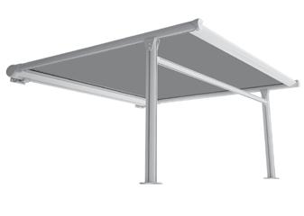
1 Albatros/Albatros Plus Albatros SINGLE MODULE Albatros DUAL MODULE Albatros PLUS Assembly manual
2
3 Assembly manual Albatros/Albatros Plus SUMMARY 1 Introduction Symbols used in the manual Requirements on the staff Required equipment Before initiating the assembling Safety General safety information Requirements to work safely Work environment... 3 Technical tables for assembly Guide support feet distance diagram (Albatros) and column position (Albatros Plus) Individual module cutting measurements Double module or multimodular cutting measurements Preloaded springs Min./ max dimensions based on the springs with Screen-Soltis fabric Spring tension with Screen-Soltis fabric Min./ max dimensions based on the springs with Acrylic fabric Spring tension with Acrylic fabric Albatros e Albatros Plus components Exploded view Albatros Exploded Albatros Plus Components...10 Fabric assembly on the winder pipe Pulley assembly Assemble the box plugs Insert the motor Spring assembly Preload the springs with the Screen-Soltis fabric Preload the springs with the Acrylic fabric Inserting the cord Select and fasten the feet Albatros Plus column assembly Double Module or Multimodular Assembly Central joint assembly with small plates with a pin Central joint assembly with small plates with a pin and motor Assemble the central joint with two motors Assembly of the motor Table choice of engines Packing...22 rev.06 2/07/11 3
4 Albatros/Albatros Plus Assembly manual 1 Introduction This awning manual was prepared by the Manufacturer to provide those authorized to assemble the components that make up the product with the necessary information. It is prohibited to remove, rewrite or in any way modify the pages of the manual and their content. Assembly must be carried out by personnel with the technical and professional skills required by current applicable national laws or standards (see chap. 1.2 Personnel requirements ). This manual should be kept intact in all its parts and in an easily accessible place. The manufacturer reserves the right to update the manufacturing and manuals, with no obligation to update previous manufacturing and manuals. The manufacturer reserves all rights on this manual. no complete or partial reproduction is permitted without writtenconsent thereto. 1.1 Symbols used in the manual The symbols used in the manual are shown below. Useful suggestions and instructions to ensure proper assembly of the awning. Failure to observe these messages may compromise the integrity and/or the resistance of the product. Danger to the operator! Instructions to be evaluated and followed carefully. Failure to comply with these messages may compromise individual safety. 1.2 Requirements on the staff The team dedicated to this operation must be in possession of a technical knowledge of product, with at least two years of experience or an appropriate course within the technical training. 1.3 Required equipment To ensure proper assembly of the mechanical part and of the fabric part, and as a result the proper operation of the finished product, you will need the following equipment: fabric rewinder frame; awning assembly frame with vertically mobile positioning bar; screwdriver; a level; complete tool kit; equipment for working at high levels (jolts, ladders, scaffolding, working platforms, etc.) that comply with existing safety regulations for persons on job. All of the screws used on aluminium components must be tightened with a maximum force of 20Nm (=2Kgm). Maximum force by tightening the screws can cause rupture of mergers and damage to the screw steel. It is recommended to use torque wrenches and screwdrivers. 1.4 Before initiating the assembling Before starting the assembly, the technician must have already done the cutting guides, profiles and roller tube depending on the size of the extendable awning that is desired (see Chapter 3.2 and 3.3 Size cutting table ). 2 Safety 2.1 General safety information Do not set objects on the canvas of the awning. It is prohibited to stand on or hang from the awning: This would create the risk of severe personal injury, as well as damaging the awning. 4 rev.06 2/07/11
5 Assembly manual Albatros/Albatros Plus Wear protective clothing and equipment required by the applicable standards of safety in workplaces. Assembly of components must be carried out only by skilled, specialized personnel. 2.2 Requirements to work safely Installation should be done in full compliance with the DPR Legislative Decree 164/6 and 494/96 for everything that concerns the safety of persons. Before use, check that all temporary structures (scaffolding, ladders, etc.) and all individual safety gear (harnesses, belts, etc.) are compliant with standards and in good condition. Always use appropriate personal protective equipment. If the installers are more than one, you must coordinate the work. Operators must conduct themselves in accordance with received safety instructions. If the extendable awning is to be mounted to a plane higher than the earth, it is necessary to demarcate and patrol the area during the climb to the floor of the extendable awning so that no one is under any suspended load. Firmly tie the ropes or straps around the arm supports so that it does not slip and risk falling. 2.3 Work environment Assembly of components must be carried out in a place that is sufficiently illuminated (based on specific standards) by either natural or artificial lighting. The operator must in fact have good visibility for the work involved, and must also prevent any third person being near to the extendable awning working area. 3 technical tables for assembly 3.1 Guide support feet distance diagram (Albatros) and column position (Albatros Plus) Albatros The guide support feet adjust the awning position. For protrusions exceeding 300 cm, a third foot is added. See Fig. 1 (measurement in cm). Albatros PLUS Position the column bar about 20cm from the guide cap. max protrusion 400 for protrusions > min 260 max 360 B/2 B/2 B min 100 max 00 fig. 1 fig. 1a rev.06 2/07/11
6 Albatros/Albatros Plus Assembly manual 3.2 Individual module cutting measurements TABLE WITH THE SIZES OF THE INDIVIDUAL MODULE (measurements in mm) L indicates the total awning size, H=height, SP=projection Albatros Albatros PLUS UPPER AND LOWER BOX SOMFY MOTOR A-110 A-110 GUIDING RAIL SOMFY MOTOR SP-18 SP-18 TERMINAL SOMFY MOTOR A-13 A-13 COVER SOMFY MOTOR A-13 A-13 REWINDER TUBE SOMFY MOTOR A-7 A-7 WINDBREAKER SOMFY MOTOR A-12 A-12 SOMFY MOTOR A-14 A-14 FABRIC THE FABRIC IS ATTACHED 3 MM FROM THE EDGE OF THE ROLLER TUBE FROM THE MOTOR SIDE COLUMN MOTORE SOMFY - H-36 COLUMN S CROSSBAR PROFIL MOTORE SOMFY - A-13 An awing L in length equal to A. is produced with these measurements. 3.3 Double module or multimodular cutting measurements A B C D box cap box cap central joint central joint front view motor motor motor bird's eye view fig. 2 6 rev.06 2/07/11
7 Assembly manual Albatros/Albatros Plus TABLE WITH THE SIZES OF THE DOUBLE OR POLYMODULARMODULE Albatros AND Albatros PLUS (measurements in mm) MOTOR MODULE B MODULE C MODULE D GARBAGE BIN UPPER AND LOWER SOMFY MOTOR B-108 C-106 D-108 GUIDING RAIL SOMFY MOTOR SP-18 SP-18 SP-18 TERMINAL SOMFY MOTOR B-133 C-130 D-133 COVER SOMFY MOTOR B-133 C-130 D-133 REWINDER TUBE SOMFY MOTOR B-6 C-4 D-6 WINDBREAKER SOMFY MOTOR B-120 C-90 D-120 FABRIC SOMFY MOTOR B-143 C-140 D-143 THE FABRIC IS BLOCKED 3MM FROM THE MOTOR SIDE. COLUMN SOMFY MOTOR H-36 H-36 H-36 COLUMN S CROSSBAR PROFIL MOTORE SOMFY B-104 C-73 D-104 To read the table, refer to fig. 2, page 6. An awing L in length equal to A. is produced with these measurements. 3.4 Preloaded springs The springs are preloaded as described on page 13. The following tables explain how to open the awning to obtain the right preload. The measurements are indicative Min./ max dimensions based on the springs with Screen-Soltis fabric SPRING AWNING SIZE (measurements in m) SPRING 4MOL_ SPRING 9MOL MINIMUM MEASUREMENTS MAXIMUM MEASUREMENTS Minimum WIDTH PROTRUSION WIDTH PROTRUSION maximum minimum maximum rev.06 2/07/11 7
8 Albatros/Albatros Plus Assembly manual Spring tension with Screen-Soltis fabric The minimum preload of the springs with Screen-Soltis fabric is about 20/30mm when the awning is closed. This measurement is valid for all the awnings of realizable dimensions. (see table , p. 7). For the type of springs to use based on the dimensions, refer to table MOL TYPE SPRING Resting length = 364 (measurements in mm) Maximum length = 700 (measurements in mm) 4MOL TYPE SPRING Resting length = 40 (measurements in mm) Maximum length = 870 (measurements in mm) Min./ max dimensions based on the springs with Acrylic fabric SPRING AWNING SIZE (measurements in m) SPRING 4MOL SPRING 9MOL MINIMUM MEASUREMENTS WIDTH minimum PROTRUSION maximum MAXIMUM MEASUREMENTS WIDTH minimum PROTRUSION maximum Spring tension with Acrylic fabric TIGHTENING THE ACRYLIC Albatros AWNING FABRIC WIDTH in m PROTUSION in m TOTAL LENGTH OF THE SPRINGS WHEN THE AWNING IS HALF OPEN 9MOL TYPE SPRING 4MOL TYPE SPRING Resting length = 364 (measurements in mm) Resting length = 40 (measurements in mm) Maximum length = 700 (measurements in mm) Maximum length = 870 (measurements in mm) 8 rev.06 2/07/11
9 Assembly/installation manual Albatros/Albatros Plus 4 Albatros and Albatros PLUS Components Key 4.1 Exploded View of Components 1 Cassette end cap and guide end cap 2 Ø80mm Rollerbat 3 Ø80mm cap with Ø14mm hole and bearing 3/1 Ø80mm cap with Ø14mm hole 4 Albatros profile set Tightening kit and front bar caps 13 6 Ø19mm spring Guide profile Ø 60mm windbreaker profile 9 Ø60mm cap with threaded pin 10 Supports for windbreaker Middle cassette end caps and middle guide end caps Middle guide profile 13 H30 plate with sliding round pin 14 Gasket 1 Ø3mm polyester rope 16 Brush for cassette Albatros 17 Adjustable guide support on the side 17/1 Inclinable and adjustable guide support 17/2 Adjustable guide support 17/3 Internal niche supports Profile for guide supports Albatros PLUS 19 Cassette wall brackets 20 Cassette ceiling brackets Universal profile 22 Perimeter support for guide 23 T shaped joint /2 17/3 24 Foot 2 Angular support 26 26mm over-roof bracket /1 fig. 1 rev.06 2/07/11 9
10 Albatros/Albatros Plus Assembly/installation manual 4.2 Exploded Albatros Plus Components fig rev.06 2/07/11

.")

 or, alternatively, the one with the hole (C). fig.")
11 Assembly manual Albatros/Albatros Plus Fabric assembly on the winder pipe The instructions which follow are of a general nature and must therefore be adapted to the model of awning being assembled. E To make this easier, it is advisable to temporarily fasten the rewinder tube to the canvas rewinder frame. A B C fig. 3 Apply two rivets on both sides of the tube (E). Be careful when attaching these rivets: they should be slightly inclined (between the fabric and the groove) in order to guarantee correct blockage. 6 Pulley assembly Instructions for installation are described in the "Installation Manual". fig. 3 1 On the control side of the roller tube, insert the cap with the square pin (A). 2 On the opposite side, insert the round pin cap (B) or, alternatively, the one with the hole (C). fig. 6 6 Insert the brush and the seal in the lower box. fig. 4 3 Place the previously packaged fabric in the nose cone of the winder pipe and slide to the opposite side. 4 Rotate the roller tube in the right direction taking care on the command side rev.06 2/07/11 11
. 6.1 Assemble the box plugs F N M fig.")
. 14 Attach the box cap to the engine (N). 26mm >30mm H collar O P washers fig.")
12 Albatros/Albatros Plus Assembly manual G 11 With the awning wound, wrap the cord around the pulley once or twice (L). 12 From the cap side, position the roller tube in the lower corner of the container (I). 6.1 Assemble the box plugs F N M fig. 7 7 Position the winding pulley from the lateral engine without locking it with the beads (G). 8 Position the winding pulley so it is in contact with the cap and locking it with the beads (F). fig Assemble the box plus with the small plate with the pin (M). 14 Attach the box cap to the engine (N). 26mm >30mm H collar O P washers fig. 8 9 Calculating the cord length to use: Cord length = (awning width + awning protrusions) x 4 10 Insert the cord inside hole (H) of the pulley, knotting it on both sides of the tube. (see fig. 8) Insert the cord in the hole on the side of the collar. fig Check that the size of the engine head allows the pulley to be positioned at about 26 mm from the box cap (O). If the engine size is greater than 30 mm, add two or more washers next to the diverter pulleys (P) to compensate the difference and block its stroke. I L fig rev.06 2/07/11

 about half a meter from one another along the terminal to drain the water.")
. fig.")

13 Assembly manual Albatros/Albatros Plus Insert the motor Inserting the motor can be done in two ways: MODULE A 1st hole 2nd hole S T fig Once the engine is hooked to the box cap, insert it in the roller tube. 17 Block the pulley by using the beads. fig Create two 8 mm holes (S) about half a meter from one another along the terminal to drain the water. MODULE B Q 21 Attach the blocking clamp on the terminal (T). fig Enter the engine in the roller tube and attached the box cap to the box (Q). fig Roll up the canvas and insert the lower edge in the terminal ferrule. R fig Pass the cord through the box cap in both sides of the roller tube, checking that it goes above the small pulley (R). U fig Fasten the canvas onto the terminal using one screw (U) per side. The screws should be slightly inclined (between fabric and frame) to ensure proper locking. rev.06 2/07/11 13

14 Albatros/Albatros Plus Assembly manual 6.2 Spring assembly fig Insert the springs in the sheaths. The springs can be inserted later. Nevertheless, we suggest assembling them with the caps before attaching them to the terminal Preload the springs with the Screen-Soltis fabric 26 With the awning closed, after having blocked the cords inside the terminal, preload the springs by pulling the cords separately until both lengthen the minimum value indicated on page Ensure that the dual pulley is half the length of the terminall 28 Check that when the awning is completely open, the springs do not touch The spring preload value can change based on the elasticity of the fabric, respecting the minimum prescribed value Each preloaded cm increases the the length of the completely open awning springs. To improve the fabric tightness, increase the preload, keeping the maximum length allowed in mind. 29 When the awning is completely open, ensure that the length does not exceed the maximum values indicated in paragraph on page Preload the springs with the Acrylic fabric fig Position the springs above the terminal and attach the caps to the screws (lubricate the springs with silicon grease). To tighten the springs, refer to the tables on page 7-8 and carefully follow the instructions. 30 After blocking the cords inside the terminal, open the awning for up to half of its protrusion 31 Pull the cords separately so both springs reach their determined length 32 Ensure that the pulley is half the length of the terminal 33 Check that the cord is taut when the awning is closed 34 Check that when the awning is completely open, the springs do not touch 3 The preload spring measurements are indicative and can vary based on the elasticity of the fabric 36 Each preloaded cm increases the the length of the completely open awning springs. To improve the fabric tightness, increase the preload, keeping the maximum measurements allowed in mind. When the awning is completely open, you must ensure that the length does not exceed the maximum values indicated in awning tightening table on page 8. The springs are preloaded in two different ways based on the awning fabric. 14 rev.06 2/07/11
.")
.")


15 Assembly manual Albatros/Albatros Plus 6.3 Inserting the cord fig Place the small plates in the guide section bars (V). (For each guide section bar, include: 2 small plates for the cassette cap, 1 for the guide cap and 2 for each foot; if you want to add a windbreaker, include another small plate). V fig Pass the cord through the terminal cap pulley and through the hole. To assemble Albatros Plus, include 2 small plates for each rail to attach the angular joint. fig Assemble the rails by keeping the cord taut so that it does not come out of the pulleys. fig Pass the cord under the rail cap pulley. fig Pass the cord exiting the terminal cap through the dual compensation pulley. rev.06 2/07/11 1


: variable height foot (this is foot (2) with an aluminium bar that helps")
: variable height foot and 90 incline 1) 7 90 K 27 Z 70 3 9 6 Y 64 fig.")
. 6 fig.")
16 Albatros/Albatros Plus Assembly manual 6.4 Select and fasten the feet blocking clamp fig Thread the sheath and pass the second cord through the dual pulley. Before blocking it, make a knot in the cords. 43 Block the cords with the blocking clamp fig. 28 Four types of feet can be used: (1): foot for horizontal-lateral adjustments; (2): foot for vertical adjustments; (3): variable height foot (this is foot (2) with an aluminium bar that helps increase the distance from the porch). (4): variable height foot and 90 incline 1) 7 90 K 27 Z Y 64 fig Insert the brush in the upper box (Z). 4 Attach to the plastic covers to the box cap (V). 46 Place the cover bar on the terminal (K). 6 fig. 29 Foot clearances for horizontal-lateral adjustments. 2) mm 20 mm A B fig Use the extra screws to attach the box caps to the rails Foot clearance for vertical adjustments: minimum height (A); maximum height (B) fig rev.06 2/07/11
.")

 to have")


.")
17 Assembly manual Albatros/Albatros Plus 3) C , fig. 31 Variable height foot. Advised rail height, see (C). For the minimum and maximum foot measurements, refer to fig. 33, page 17. fig Assemble the supports selected to install the awning. 4) D fig. 32 Variable height foot. For the minimum and maximum foot measurements, refer to fig. 33, page 17 A fig For sizes exceeding 4x4m, we suggest assembling the windbreaker roller (D) to have more fabric tension. 7 Albatros plus column assembly E F G L I H 41 A min 70 max 200 fig Insert the small plates (G) in the column rail (H) that are used to attach the perimeter support. 1 Insert the other two small plates in one side of the column rail (H) only to attach the perimeter support. fig. 33 Albatros interaxial feet, single module. A = awning width, (measurements in mm). Insert two small plates in the slot (I) on the universal rail to fasten the angular support. 2 Attach the small plate (F) with four screws (E) to the universal rail (H). rev.06 2/07/11 17
. N fig.")

 to the universal rail (O) using four screws (P).")

 in positions 1 and 2 indicated in figu")
18 Albatros/Albatros Plus Assembly manual 8.1 Central joint assembly with small plates with a pin M fig Attach the foot to the universal rail/column using screws (M). N fig. 40 Left central joint with small plate with a pin for the multimodular Albatros with the motor on the opposite side. 9 Attach the small plate with the pin on the central joint using the appropriate screws. P O J fig Insert two small plates (J) in the universal rail (O) to fasten the angular support. Attach the perimenter support (N) to the universal rail (O) using four screws (P). 8 Double Module or Multimodular Assembly fig Assemble the left central joint to the lower box. Before attaching the joint to the box, check that the tube pulley is aligned with the small central joint pulley. To fasten the joint to the box, make holes for the screws with a Ø2.8/3.0 bit (3. mm screws) in positions 1 and 2 indicated in figure 42 and 43. fig. 39 The assembly procedure is similar to the one for the single Albatros. There are 3 configurations for the central joint: 6. central with two small plates with a pin 7. central with one small plate with a pin and motor 8. central with two motors 18 rev.06 2/07/11


19 Assembly manual Albatros/Albatros Plus fig. 42 fig Repeat the assembly operation for the right central joint and attach it to the left central joint using the appropriate screws 1, 2 and 3. R fig Fasten the joint with the box using self-threading screws. fig Insert the upper box in both sides; make the hole in the position indicated in figure 3 (hole no. 3) and attach it with screws (R). 8mm Q fig Assemble the central rail to the central joint and attach it using the appropriate screws (Q) To transfer the cord, follow the same procedure for the single Albatros module. fig Assemble the canopy and make a hole with a Ø3.8/4mm bit (screws from 4.8mm), 8mm from the outside edge. 66 Attach it to the central joint with a self-threading screw. rev.06 2/07/11 19


20 Albatros/Albatros Plus Assembly manual When large awnings have to be assembled and they cannot be assembled in the workshop, assemble the left part, then the right part and then test them separately. To support the central rail when the right part is assembled, make a hole near the central joint tab (see Fig. 48 (S)). fig Assemble the central joint with the lower box and attach it with the appropriate screws (to position the screws, see fig. 42 and fig. 43, page 19). 8.3 Assemble the central joint with two motors S fig Central joint assembly with small plates with a pin and motor To assemble the awning with two motors, see the instructions in section 7.2. Repeat the operation on the opposite side of the awning. 9 Assembly of the motor The following instructions are general in nature and must therefore be adapted to the model of the engine that is being assembled. Follow the instructions in the manual as supplied with the requested motor. U Z T W fig To assemble the left part, follow the instructions in section 8.1 Central Joint Assembly with Small Plates with Pin. 68 For the right part of the awning, insert the roller tube (T) motor and attach the motor plate to the central joint using the appropriate screws. 69 Check that the tube pulley is aligned with the small central joint pulley. Z fig.1 71 Insert the crown (Z) into the tube from the motor side. 72 Rotate the crown until complete match up of their locations of interlocking crown-engine (W) until it clicks. 20 rev.06 2/07/11

21 Assembly manual Albatros/Albatros Plus U V fig Insert the adapter (U) in the other side, ensuring that there is a proper joint. Insert the appropriate fixed engine staple (V). Having assembled the awning and the engine, adjust the limit switches by following the instructions in the "Engine Manual" attached. 9.1 Table choice of engines Albatros AWNING MOTOR TABLE WIDTH in m PROTRUSION in m Nm 0Nm 4 rev.06 2/07/11 21


22 Albatros/Albatros Plus Assembly manual 10 PACKING bubble wrap be careful when moving the awning. If necessary, use suitable lifting and moving equipment. Also make sure that there are no people in the work area. extendible film fig Package the rails with extendible film. fig Close the awning completely. 7 Remove the caps from the rails on both sides of the awning. 76 Remove the cover rail from the terminal. To package the double module, wrap the central joint first with bubble warp; position the previously packaged side rails externally and package everything with extendible film (see fig. 4). cover rail terminal fig. 7 fig Individually package the rail caps with bubble wrap and place it above the terminal, leaving the cord attached. 78 Attach them to the box with extendible film. fig. 79 Remove the box cap rails and package them individually. fig.8 81 Package the box with the terminal cover bar with bubble wrap, being careful to keep the two bars separate to avoid dragging them. 22 rev.06 2/07/11
23 KE PROTEZIONI SOLARI srl Via Calnova, 160/a Noventa di Piave (VE) Italy tel fax Via Mateotti, 21/ Rancio Valculvia (VA) Italy tel fax
TUCSON PATIO AWNING INSTALLATION MANUAL
 TUCSON PATIO AWNING INSTALLATION MANUAL Toll Free 877-792-1775 Fax 877-792-0031 swsuncontrolpro.com sales@swsuncontrol.com 1 INTRODUCTION...3 1.1 Symbols used in this manual... 3 1.2 Personnel requirements...
Ely Cagliari. for installation
 Ely Cagliari manual for installation All information contained in this document was provided by the manufacturer of the components for this model. As a fabricator, Retractableawnings.com claims no liability
SOLHARO ASSEMBLY & INSTALLATION INSTRUCT IONS
 A. Introduction: SOLHARO ASSEMBLY & INSTALLATION INSTRUCT IONS Rev. 01/30/2012 The Solharo is an external, retractable, tensioned sun shading system designed to fit over a sunroom or wood pergola. The
INSTALLATION INSTRUCTIONS AND OWNER'S MANUAL AWNINGS. For trailers & motor homes with straight sides TOOLS REQUIRED
 AWNINGS INSTALLATION INSTRUCTIONS AND OWNER'S MANUAL For trailers & motor homes with straight sides TOOLS REQUIRED 1/4" electric drill Ratchet handle kit 3/8" & 7/16" socket No. 1 and No. 2 screwdriver
ALPINE SLIDEOUT COVER
 INSTALLATION MANUAL ALPINE SLIDEOUT COVER RV Read this manual before installing or using this product. Failure to follow the instructions and safety precautions in this manual can result in personal injury
Cassette-folding arm-awning markilux 990
 Cassette-folding arm-awning markilux 990 Mounting instructions 1. Overview 1 Projection profile 2 Folding arm 3 Fabric 4 Console 5 Cassette 6 Covering cap 7 Wall bracket 2. Mounting brackets 2.1 Overview
TUCSON PATIO AWNING USE & MAINTENANCE
 TUCSON PATIO AWNING USE & MAINTENANCE Toll Free 877-792-1775 Fax 877-792-0031 swsuncontrolpro.com sales@swsuncontrol.com 1 INTRODUCTION...3 2 SAFETY...3 2.1 General safety information... 3 2.2 Safety devices...
TENDABOX BX3000. Cassette awning with folding arms BX3000. Description. Options:
 TENDABOX Description One-piece U-shaped protective cover (Dimension 179 x 145 mm), as from 500 cm total width protective cover inner reinforcement (Dimension 179 x 145 mm), of extruded aluminium profile
Solera Classic Awning OEM INSTALLATION MANUAL
 Solera Classic Awning OEM INSTALLATION MANUAL TABLE OF CONTENTS System and Safety Information 2 Preparation 3 Resources Required 3 Installation 3 Installing the Awning Rail (If Necessary) 3 Assembling
Installation Instructions for the Rolltec Adalia X3M Extenda Awning
 Installation Instructions for the Rolltec Adalia X3M Extenda Awning Questions? Call Rolltec at 1-800-667-0474 General Tool Requirements Table of Contents Available installation brackets Side dimensions
RETRACTABLE AWNING w/ OPTIONAL HOOD ASSEMBLY INSTRUCTIONS
 Contact us @ (800)851-0865 RETRACTABLE AWNING w/ OPTIONAL HOOD ASSEMBLY INSTRUCTIONS Congratulations on your purchase of a new retractable awning. With proper installation this awning will provide years
AND LOAD CANOPY RACK SPECIFICATIONS
 8MAY15 INSTRUCTIONS for the LOCK AND LOAD CANOPY RACK SPECIFICATIONS and SAFE LOADING REQUIREMENTS The Lock and Load ladder carrier for Truck Caps is a rack designed to mount to the top of a pickup truck
Installation Instructions for the Rolltec Bravo Awning
 Installation Instructions for the Rolltec Bravo Awning Questions? Call Rolltec at 1-800-667-0474 Table of Contents Available installation brackets Side dimensions of various installations Determining installation
quick and easy installation guide
 www.directdriveopener.com quick and easy installation guide Back 2 Front. Motor Carriage 2. C-rail. Chain. Limit stops. Slide in part (tensioner) Rail assembly Insert C-rail parts () into the connecting
INSTRUCTION MANUAL ALEKO RETRACTABLE AWNING
 INSTRUCTION MANUAL for ALEKO RETRACTABLE AWNING www.alekoproducts.com FAILURE TO FOLLOW THESE INSTRUCTIONS MAY RESULT IN PERSONAL INJURY! 1 Important Safety Precautions WARNING NOTE: FOR PERSONAL SAFETY,
Item #: BTOT Assembly Instructions
 Item #: BTOT Assembly Instructions For our most current instructions, to request missing, lost or broken parts, or for any other Customer Service issues, please visit our website at www.walkeredison.com
FLEX KEY ASSEMBLY. ..._ o RAFTER ARM TUBE MAIN ARM TUBE CAP NUT CLAW HINGE
 ZIP DEE Inc. 96 Crossen Ave. Elk Grove Village, IL 60007(847)437-0980 (800)338-2378 HEAD CASTING AWNING RAIL FLEX KEY ASSEMBLY..._ o GM1 Installation Instruction GMC Motorhome RAFTER ARM TUBE MAIN ARM
Primrose Awnings Full Cassette Manual & Electric Instructions
 Primrose Awnings Full Cassette Manual & Electric Instructions Contents for Full Cassette Awning 1 x Remote control receiver box 2 x Remote hand-held zappers 1 x 5 metre cable 1 x Template sticker **The
DO NOT use Alien Flier Zip Line Products until you have read and fully understand the SAFETY WARNINGS below!
 SAFETY WARNING DO NOT use Alien Flier Zip Line Products until you have read and fully understand the SAFETY WARNINGS below! Assumption of Risk Zip line construction and use can be dangerous. Ensure you
ORDER FORM B B2100
 Date: ORDER FORM B2085 - B2100 Delivery address: Name: Address: Ref. customer: Tel. n : Quantity:... Type of awning: o Brustor B2085 o Brustor B2100 B2085: H = U + 120 mm B2100: H = U + 137 mm Total width:...mm
Installation Instructions for the Rolltec Physique XL Awning
 Installation Instructions for the Rolltec Physique XL Awning Questions? Call Rolltec at 1-800-667-0474 General Tool Requirements Table of Contents Available installation brackets Side dimensions of various
Installer and user s manual VARANDA AWNING INFORMATION PRE-INSTALLATION
 Installer and user s manual VARANDA AWNING 2 persons Necessary tools INFORMATION PRE-INSTALLATION Important! efore the installation, check the leveling of the place where you will apply the awning. Dimensions
Contents. Awnings USA - Full Protective Hood Manual Instructions ft 11" - 11ft 6" Awnings
 Awnings USA - Full Protective Hood Manual Instructions Contents Warning We recommend that two or more people are required to lift the awning into place. 4ft 11" - 11ft 6" Awnings 8 x Expansion bolts **
300 ft. 5/8 Hose wagon
 300 ft. 5/8 Hose wagon Model 95956 Assembly And Operation Instructions Due to continuing improvements, actual product may differ slightly from the product described herein. (Garden hose is not included).
Motorized Oasis Awning RTS Motor Cord Replacement Instructions *Helpers Needed*
 RETRACTABLE AWNINGS For Technical Support visit us at www.sunsetter.com/ownerscorner or Call Toll Free 800-670-7071 Fax 877-224-4944 Motorized Oasis Awning RTS Motor Cord Replacement Instructions *Helpers
NEWMAR SERVICE SCHOOL
 NEWMAR SERVICE SCHOOL TRAINING INFORMATION GUIDELINE FOR FEBRUARY 2013 OUR PRODUCTS: NOVA DUAL PITCH AWNING G-2000/ G-1500 2 P a g e G-2085 G-5000 3 P a g e G-LINKS 4 P a g e NOVA/ G-2000/ G-1500 BASIC
Installation Instructions Traditional Awnings in a box Classic Awnings in a Box
 Installation Instructions Traditional Awnings in a box Classic Awnings in a Box Basic Tools Required (not included) Tape Measure & Pencil Level Phillips Screwdriver Drill with ¼ bit (Cement or Masonry
Primrose Awnings Half Cassette Manual & Electric Instructions
 Primrose Awnings Half Cassette Manual & Electric Instructions Contents for 2.5m, 3m Awnings 4 x Expansion bolts (2 per bracket)** 2 x brackets 1 x Awning Contents for 3.5m, 4m Awnings 6 x Expansion bolts
Advantage Plus TIM-3600 Series Reel
 Read the following precautions and instructions before you begin assembly or using. Failure to comply with these instructions could result in personal injury or property damage. Keep these instructions
Urea/Adblue Hose Reel
 www.scintex.com.au sales@scintex.com.au Model: SHR3408 Urea/Adblue Hose Reel Product Manual Specifications Spring driven drum: for automatic rewind. Locking ratchet: to maintain the desired length of hose
Primrose Awnings Half Cassette Manual & Electric Instructions
 Primrose Awnings Half Cassette Manual & Electric Instructions Contents Contents for 2m, 2.5m, 3m Awnings 2 x wall brackets 4 x expansion bolts (2 per bracket)** 1 x Awning Contents for 3.5m, 4m and 4.5m
ORDER FORM B B B1100 windproof
 ORDER FORM B1085 - B1100 - B1100 windproof Date: Delivery address : Name: Address: Ref.customer: Tel. n : Quantity:... Type of awning: o Brustor B1085 o box 85mm o Brustor B1100 o box 105mm o Standard
Model Max. Surface m 2 Min. Width mm Max. Width mm Min. Height mm Max. Height mm Solar Guard , ,000
 AWNINGS Awnings STRAIGHT DROP Ideal for glass facades, window areas and buildings with a particular need for sun protection. Heat protection due to the reflection of the sun before it reaches the glass
OPERATOR INSTRUCTION MANUAL INCLUDING REPAIR PARTS FOR MODULAR GENERAL PURPOSE TENT SYSTEM (MGPTS) TYPE I
 TYPE I") OPERATOR INSTRUCTION MANUAL INCLUDING REPAIR PARTS FOR MODULAR GENERAL PURPOSE TENT SYSTEM (MGPTS) TYPE I Johnson Outdoors Gear, Inc. Eureka! branded tent products 625 Conklin Road Binghamton, NY 13903
OPERATOR INSTRUCTION MANUAL INCLUDING REPAIR PARTS FOR MODULAR GENERAL PURPOSE TENT SYSTEM (MGPTS) TYPE I Johnson Outdoors Gear, Inc. Eureka! branded tent products 625 Conklin Road Binghamton, NY 13903
Roller Bar End Cap (w/round Drive Shaft) Replacement Instructions for Vista and Motorized Awnings * Helpers needed *
 Replacement Instructions for Vista and Motorized Awnings * Helpers needed *") RETRACTABLE AWNINGS For Technical Support visit us at www.sunsetter.com/ownerscorner or Call Toll Free 800-670-7071 Fax 877-224-4944 Roller Bar End Cap (w/round Drive Shaft) Replacement Instructions for
RETRACTABLE AWNINGS For Technical Support visit us at www.sunsetter.com/ownerscorner or Call Toll Free 800-670-7071 Fax 877-224-4944 Roller Bar End Cap (w/round Drive Shaft) Replacement Instructions for
INSTALLATION INSTRUCTIONS for automatic awnings
 Custom made Awnings and Blinds Item No 0756 INSTALLATION INSTRUCTIONS for automatic awnings AUTOMATIC AWNING IMPORTANT INFORMATION BEFORE INSTALLING YOUR AUTOMATIC AWNING Updated 08/09/15 AN AWNING INSTALLATION
INSTALLATION INSTRUCTIONS for folding arm awnings
 Custom made Awnings and Blinds Item No 0757 INSTALLATION INSTRUCTIONS for folding arm awnings IMPORTANT INFORMATION BEFORE INSTALLING YOUR Updated 08/09/15 AN AWNING INSTALLATION IS A HOME IMPROVEMENT
RAFTER VI. Installation and Operation CAREFREE WITH AUTOMATIC AWNING SUPPORT. RV Accessory PRODUCT OVERVIEW
 CAREFREE RAFTER VI RV Accessory WITH AUTOMATIC AWNING SUPPORT Installation and Operation PRODUCT OVERVIEW The gives the awning user the ability to easily tighten the center fabric when the awning is extended.
Primrose Awnings - Standard Manual Instructions
 Primrose Awnings - Standard Manual Instructions Contents Warning 1.5m - 3.0m Awnings 4 x Expansion bolts (2 per bracket)** 2 x brackets 1 x Awning 1 x Winder handle 3.5m - 4m Awnings 6 x Expansion bolts
Solera Power Awning OEM INSTALLATION MANUAL
 Solera Power Awning OEM INSTALLATION MANUAL TABLE OF CONTENTS System Information 2 Safety 2 Prior To Installation 2 Resources Required 2 Awning Rail Installation (If Needed) 3 Installation 3 Awning Installation
Section 11 Workstation Components
 1 Section Quick and easy access to parts is made possible by the wide variety of trays, bins, and framing components available from Bosch. Individual workstation grab trays, containers, and ledges place
Installation manual. Awning. V480 Cannes
 Installation manual Awning V480 Cannes Installation manual awning V480 Cannes Content 1. Awning * 2. Wall supports 3. Extra support(s) (with an awning bigger than 350 cm) 4. Mounting plates (optional)
Primrose Awnings - Full Cassette Manual & Electric Instructions
 Primrose Awnings - Full Cassette Manual & Electric Instructions Contents Warning 2.0m - 3.5m Awnings 8 x Expansion bolts ** 2 x brackets 1 x Awning 1 x Winder 4.0m - 5.0m Awnings 12 x Expansion bolts **
12 Cage Installation Instructions
 Important Notes 12 Cage Installation Instructions 1) The long pipes are the for vertical sections only. The cage is 10 tall. 2) The cross fittings should be oriented with the slide through running front
PL500A Platform Extension
 PL500A Platform Extension Operator Manual Copyright 2009 ServerLift Corporation 821 N 2nd Street Phoenix, AZ 85004 VOICE: 602.254.1557 FAX: 602.412.4479 821 N 2nd Street Phoenix, AZ 85004 VOICE: 602.254.1557
--- BIG LEAGUE BATTING CAGE ---
 --- BIG LEAGUE BATTING CAGE --- BGLC-7500 Call Jaypro Sports Equipment at 1-800-243-0533 during regular business hours for technical support. www.jaypro.com Rev-B Page 1 of 22 IMPORTANT NOTICE: 1. BEFORE
ADDED PROTECTION FOR SLIDE-OUT ROOMS. Installation. Introduction... 2 Product Overview...2 Component Checklist...3
 CAREFREE SIDEOUT KOVER II RV Installation ADDED PROTECTION FOR SLIDE-OUT ROOMS TABLE OF CONTENTS SOKII Shown with Full Case Option Introduction... 2 Product Overview...2 Component Checklist...3 Installation...
Sun awning V225 Porto
 Installation manual Sun awning V225 Porto semi-cassette Content package 1. Sun awning * 2. Control a. Manual control: crank handle b. Electrical: switch + plug c. Remote controlled: remote control + plug
WINDOW AND OVER THE DOOR (OTD) AWNINGS
 AWNINGS") RV SERVICE MANUAL MARQUEE WINDOW AND OVER THE DOOR (OTD) AWNINGS Read this manual before installing or servicing this product. Failure to follow the instructions and safety precautions in this manual can
RV SERVICE MANUAL MARQUEE WINDOW AND OVER THE DOOR (OTD) AWNINGS Read this manual before installing or servicing this product. Failure to follow the instructions and safety precautions in this manual can
VISION PATIO AWNING INSTALLATION GUIDE. Rev RV AWNING PRODUCTS
 VISION PATIO AWNING INSTALLATION GUIDE Rev. 042015 RV AWNING PRODUCTS 1361 CALLE AVANZADO, SAN CLEMENTE, CA 92673 (949) 259-4000 FAX (949)276-5500 WWW.GIRARDRV.COM Girard Systems awnings may be operated
INSTALLATION INSTRUCTIONS for vertical awnings
 Custom made Awnings and Blinds Item No 0759 INSTALLATION INSTRUCTIONS for vertical awnings IMPORTANT INFORMATION BEFORE INSTALLING YOUR Updated 08/09/15 AN AWNING INSTALLATION IS A HOME IMPROVEMENT PROJECT
Installation. Introduction... 2 Product Overview...2 Component Checklist...3
 CAREFREE SIDEOUT KOVER II RV WITH MANUAL LOCK Installation TABLE OF CONTENTS Introduction... 2 Product Overview...2 Component Checklist...3 Installation... 4 Installing the Mounting Brackets...4 Assemble
OWNER S MANUAL: G5000 SLIDE-OUT AWNING SYSTEM
 INSTALLATION, OPERATIONS, ADJUSTMENT AND REPAIR Rev. 08/01/12 1361 Calle Avanzado San Clemente California 92673 Office: (949) 259-4000 Toll Free: (800) 382-8442 Fax: (949) 276-5500 TABLE OF CONTENTS WARRANTY
INSTALLATION INSTRUCTIONS
 INSTALLATION INSTRUCTIONS Accessory FABRIC ROOF/ REAR PANEL (5P) P/N 0SR85-HL4-222A (Black) 0SR85-HL4-221C (Camo) Application SXS1000M5P/M5D Honda Dealer: Please give a copy of these instructions to your
CONVEX Awning Instructions
 CONVEX Awning Instructions IMPORTANT NOTE: Please take a few minutes to become familiar with this entire document BEFORE beginning your installation. The time you spend doing this is well spent and will
WINDOW AND OVER THE DOOR (OTD) AWNINGS
 AWNINGS") SERVICE MANUAL MARQUEE RV WINDOW AND OVER THE DOOR (OTD) AWNINGS TABLE OF CONTENTS Product Overview... 1 Canopy Replacement... 2 Spring Arm Replacement... 3 Replacing the Lead Rail Connector...4 Replacing
SERVICE MANUAL MARQUEE RV WINDOW AND OVER THE DOOR (OTD) AWNINGS TABLE OF CONTENTS Product Overview... 1 Canopy Replacement... 2 Spring Arm Replacement... 3 Replacing the Lead Rail Connector...4 Replacing
BowDown. MiniMuM Crossbar spread 24 (61CM) Steel Hook (2X) Buckle Strap (2X) Plastic Tube (2X) Plain Strap (2X) SHORT BLACK T-BOLT (2x) BOWDOWN (2x)
 Steel Hook (2X) Buckle Strap (2X) Plastic Tube (2X) Plain Strap (2X) SHORT BLACK T-BOLT (2x) BOWDOWN (2x)") BowDown MiniMuM Crossbar spread 24 (61CM) Heavy Duty strap (2x) SHORT BLACK T-BOLT (2x) BOWDOWN (2x) Bow Stern Tie Down Buckle Strap (2X) Plastic Tube (2X) Plain Strap (2X) Steel Hook (2X) IMPORTANT WARNING
BowDown MiniMuM Crossbar spread 24 (61CM) Heavy Duty strap (2x) SHORT BLACK T-BOLT (2x) BOWDOWN (2x) Bow Stern Tie Down Buckle Strap (2X) Plastic Tube (2X) Plain Strap (2X) Steel Hook (2X) IMPORTANT WARNING
Installation and User s Manual 12 x 10 MOTORIZED AWNING
 12 x 10 MOTORIZED AWNING Installation and User s Manual 12 x 10 MOTORIZED AWNING 088-1763-0 Stop Please read and understand this manual before any assembly or use of this product. Before beginning assembly
Technical data. Patio awnings
 Technical data Patio awnings Valid from 01.03.2017 WAREMA patio awnings for individual sun protection WAREMA awnings are an eye-catching feature for any building. The large choice of designs, colours and
DO NOT USE WITH CROSSBAR SPREAD LESS THAN 24.
 TM Please read all instructions carefully before assembly, installation and/or use of this product. DO NOT USE WITH CROSSBAR SPREAD LESS THAN 24. WARNING: Do not exceed the weight limit of your vehicle
INSTANT GARAGE MODEL NO: CIG81224 ASSEMBLY INSTRUCTIONS PART NO: ORIGINAL INSTRUCTIONS
 INSTANT GARAGE MODEL NO: CIG81224 PART NO: 3503578 ASSEMBLY INSTRUCTIONS ORIGINAL INSTRUCTIONS GC1117 INTRODUCTION Thank you for purchasing this CLARKE Instant Garage. When erected, the CIG81224 garage
ALEKO Victoria Series Retractable Awning Instructions for Installation and Operation
 www.alekoproducts.com ALEKO Victoria Series Retractable Awning Instructions for Installation and Operation PLEASE DO NOT RETURN THIS PRODUCT TO THE STORE! The owner s manual includes assembly and operating
Standard Awning Installation Instructions
 Standard Awning Installation Instructions Important Note: Please become familiar with this entire document BEFORE beginning your installation. The time you spend doing this is well spent and will make
HARD DOOR UPGRADE KIT
 RV Accessories OWNER'S MANUAL HARD DOOR UPGRADE KIT FOR ADD-A-ROOM & BREEZEWAY SCREEN ROOMS THIS MANUAL SUPPLEMENTS THE ADD-A-ROOM INSTRUCTIONS TABLE OF CONTENTS First Time Assembly... 2 Assembling the
JOINTED ARM AWNING SWINGLINE CASSETTE
 841003_EN JOINTED ARM AWNING SWINGLINE CASSETTE JOINTED ARM AWNING SWINGLINE CASSETTE CONTENTS Page 1. SAFETY 1.1 Explanation of the safety notes.............................................................2
Model INSTALLATION INSTRUCTIONS
 RECORD THIS UNIT INFORMATION FOR FUTURE REFERENCE: Model Number Serial Number Date Purchased USA SERVICE OFFICE Dometic, LLC 2320 Industrial Parkway Elkhart, IN 46516 574-294-2511 895(X)0(X)1.400(X) Basement
User s Manual Trampoline 8
 User s Manual Trampoline 8 Model! WARNING Read all precautions and instructions in this manual before using this equipment. Save this manual for future reference. Maximum user weight 17 lbs. ASSEMBLY IMPORTANT
Installation manual. Drop-arm awning. V120 Napoli
 Installation manual Drop-arm awning V120 Napoli Installation manual drop-arm awning V120 Napoli Content 1. Drop-arm awning * 2. Control a. Manual control: crank handle b. Manual control: strap coiler
Manual Awning. Assembly Instructions. Product No Toll-free:
 Manual Awning Product No. 088-30- Instructions Toll-free: -877-483-679 IMPORTANT: Please read this manual carefully before beginning assembly of this product. Keep this manual for future reference. 3 Table
Installation manual. Drop-arm awning. V124 Calpe
 Installation manual Drop-arm awning V124 Calpe Installation manual Drop-arm awning V124 Calpe Content 1. Drop-arm awning * 2. Wall supports 3. Control a. Manual control: crank handle b. Electrical control:
DC 700 Series Hose Reel - September 2010
 Instructions Parts List Service Manual DC 700 Series Hose Reel - September 2010 Suitable for dispensing, transfer and evacuation of lubricants, fuels, air & other automotive & industrial products. To be
Compass Home 8' x 8' No Tools Gazebo with Awning and Anchor Bags Assembly Instruction for Gazebo (no tools required)
") Compass Home 8' x 8' No Tools Gazebo with Awning and Anchor Bags Assembly Instruction for Gazebo (no tools required) CAUTION: Read all instructions before assembly. Failure to do so may result in faulty
Compass Home 8' x 8' No Tools Gazebo with Awning and Anchor Bags Assembly Instruction for Gazebo (no tools required) CAUTION: Read all instructions before assembly. Failure to do so may result in faulty
LATITUDE SERVICE MANUAL SINGLE STAGE. 12V Motorized Lateral Arm Awning w/ Direct Response
 SERVICE MANUAL LATITUDE 12V Motorized Lateral Arm Awning w/ Direct Response Read this manual before servicing or using this product. Failure to follow the instructions and safety precautions in this manual
Solera Power Awning w/ LED Lights OEM INSTALLATION MANUAL
 Solera Power wning w/ LED Lights OEM INSTLLTION MNUL TBLE OF CONTENTS Safety 2 Prior to Installation 2 Resources Required 2 wning Installation 3 wning Rail Installation (If Needed) 3 wning Support rm Installation
PEAK 1 GENERAL INFORMATION 1.1 THE CONCEPT 1.2 SAFETY 1.3 THE SPEED SYSTEM 2 THE EMERGENCY PARACHUTE 2.1 EMERGENCY PARACHUTE ASSEMBLY
 PEAK 1 GENERAL INFORMATION 1.1 THE CONCEPT 1.2 SAFETY 1.3 THE SPEED SYSTEM 2 THE EMERGENCY PARACHUTE 2.1 EMERGENCY PARACHUTE ASSEMBLY 3 ADJUSTING YOUR PEAK 3.1 ADJUSTING THE SITTING POSITION 3.2 ADJUSTING
Tarp Return. Questions? Contact Customer Or Parts Diagrams see Parts and Diagrams section on web at
 Roll Rite, LLC and its entire staff would like to not only Thank You but congratulate you on your purchase of one of what we feel to be the finest line of tarping systems in the industry. Tarp Return RR
USER MANUAL BMU WORKCAGE. CONFORM TO THE MACHINE DIRECTIVE 2006/42/EC and to EN1808 (1999)
") USER MANUAL BMU WORKCAGE CONFORM TO THE MACHINE DIRECTIVE 2006/42/EC and to EN1808 (1999) All persons operating this equipment must read and completely understand this manual. Any operation in violation
USER MANUAL BMU WORKCAGE CONFORM TO THE MACHINE DIRECTIVE 2006/42/EC and to EN1808 (1999) All persons operating this equipment must read and completely understand this manual. Any operation in violation
4.2 Assembly Instructions
 4.2 Assembly Instructions 4.2.1 Assembly of Reserve Canopy. Assembly of Reserve Canopy using Rapide Links. After inspecting the Parachute and the Wings Harness/Container System, hang or lay the parachute
Product instruction manual Ream Cutting Systems RE3943, RE3946, RE3947, RE3971, RE3952E
 Product instruction manual Ream Cutting Systems RE3943, RE3946, RE3947, RE3971, RE3952E The Trimfast Ream Cutters are reliable, high performance cutters that will give you the results you need quickly
INSTRUCTIONS INSTALLATION UNIVERSAL SERIES PATIO AWNING HARDWARE , , ,
 RECORD THIS INFORMATION FOR FUTURE REFERENCE: Model Number Serial Number Hardware Model Number Hardware Serial Number Date Purchased Retailer / Qualified Installer INSTALLATION INSTRUCTIONS UNIVERSAL SERIES
Assembling & Fitting Instruction August 2015
 Assembling & Fitting Instruction August 2015 Wave Curtain Heading System Silent Gliss 6010, 6020, 6100, 6103, 6290, 6380, 6465 Silent Gliss 3840, 6120 Silent Gliss 5090, 5200, 5400 Silent Gliss 5100, 5600
LITE Spear Awning Instructions
 LITE Spear Awning Instructions IMPORTANT NOTE: Please take a few minutes to become familiar with this entire document BEFORE beginning your installation. The time you spend doing this is well spent and
ASSEMBLY & CARE INSTRUCTIONS
 ASSEMBLY & CARE INSTRUCTIONS 7 x TRAILER TENT SERIES 3 9 Part No. FT3711 - on road FT3923 - off road OPTIONAL SUNROOM Wall and floor kit Part No. FT3723 - on road FT39 - off road OPTIONAL SPARE ROOM Roof,
Rhino-Rack SUNSEEKER Awning Black
 Rhino-Rack SUNSEEKER Awning Black 1. Check Part No./Kit is correct 3. Fit roof rack accessory 2. Read through instruction before installing 4. Check and recheck all fasteners are secure Layout 2.0m - 32132
WIDESPREAD LAVATORY MODELS WITH HI-ARC SPOUT
 5951, 5961, 5981, 5983, 5993 SERIES MT122B INSTALLATION INSTRUCTIONS THESE INSTRUCTIONS MUST BE LEFT WITH HOMEOWNER WIDESPREAD LAVATORY MODELS WITH HI-ARC TRADITIONAL CROSS NOTE: Handle Inserts are not
Core Systems Installation Instructions
 185-3017 185-3018 185-3517 607-0149 WLH 09/17/18 TABLE OF CONTENTS ***Assembly*** Roller Tube Assembly Roller Tube Assembly... Standard Application Attaching Tarp to Roller Tube - Standard... Installing
CAREFREE SL WINDOW AWNING MANUAL PULL DOWN WINDOW AWNING. Installation and Operations Manual r3 Printed in USA October, 2010
 CAREFREE RV MANUAL PULL DOWN WINDOW AWNING Installation and Operations Manual 052533-001r3 Printed in USA October, 2010 PROPRIETARY STATEMENT The SL Window Awning is a product of Carefree of Colorado,
S E L E C T I O N. Abdominal Crunch. User manual
 and S E L E C T I O N T H E S T R E N G T H E V O L U T I O N User manual and and The identification plate of the and manufacturer, affixed along side the seat on the frame of the weight stack, gives the
READ AND SAVE THESE INSTRUCTIONS! EasyAwn Standard Awning Installation
 EasyAwn Installation, Care and Maintenance Manual EasyAwn Quality, Since 1946 EasyAwn, LLC Toll Free: 877-EasyAwn http://www.easyawn.com READ AND SAVE THESE INSTRUCTIONS! EasyAwn Standard Awning Installation
Technical data. Patio awnings. 550 Cassette Folding Arm Awning
 Technical data Patio awnings 550 Cassette Folding Arm Awning Valid from 01.03.2017 WAREMA patio awnings for individual sun protection WAREMA awnings are an eye-catching feature for any building. The large
jointed arm awning _EN
 jointed arm awning TRENDLINE SUNBOX MOUNTING INSTRUCTIONs 930101_EN jointed arm awning TRENDLINE SUNBOX mounting instructions Contents Page 1. Safety 1.1 Explanation of the safety notes...3 1.2 General
ASSEMBLY & CARE INSTRUCTIONS. 7 x4 TRAILER TENT SERIES 4 9. OPTIONAL SUNROOM Wall and floor kit. OPTIONAL SPARE ROOM Roof, wall and floor kit
 ASSEMBLY & CARE INSTRUCTIONS 7 x TRAILER TENT SERIES 9 Part No. TM709 OPTIONAL SUNROOM Wall and floor kit Part No. TM723 OPTIONAL SPARE ROOM Roof, wall and floor kit Part No. TM76 Please keep these instructions
TCWS.38NG03.C BLACK DIAMOND BURNER KIT INSTRUCTIONS
 IMPORTANT: THESE INSTRUCTIONS ARE TO REMAIN WITH THE HOMEOWNER These instructions are supplementary to the Installation and Operating Instructions supplied with the fireplace and should be kept together.
FIESTA & FIESTA HD PATIO AWNINGS
 INSTALLATION MANUAL FIESTA & FIESTA HD PATIO AWNINGS MANUALLY OPERATED PATIO AWNING RV Read this manual before installing or using this product. Failure to follow the instructions and safety precautions
Assembly instructions for Eurotramp trampolines Series: Ultimate, Grand Master Exclusiv, Grand Master, Master
 Assembly instructions for Eurotramp trampolines Series: Ultimate, Grand Master Exclusiv, Grand Master, Master 1. Assembly instructions 2. Attaching the plastic coated steel cables on the Ultimate frame
NS 200 Series Hose Reel January 2011
 Instructions Parts List Service Manual NS 200 Series Hose Reel January 2011 Suitable for dispensing, transfer and evacuation of lubricants, fuels, air & other automotive & industrial products. To be used
MOTORIZED OR MANUAL LATERAL ARM BOX AWNING. Product Overview... 1 Component Checklist... 2
 INSTALLATION MANUAL FREEDOM AWNING RV MOTORIZED OR MANUAL LATERAL ARM BOX AWNING TABLE OF CONTENTS Product Overview... 1 Component Checklist... 2 Installation... 3 Attaching the Mounting Plates... 3 Mounting
TRAVEL'R ARMS AND CANOPY
 RV INSTALLATION MANUAL TRAVEL'R ARMS AND CANOPY THIS MANUAL PROVIDES INSTRUCTIONS FOR ORIGINAL EQUIPMENT MANUFACTURER (OEM), AFTERMARKET INSTALLATIONS AND ARM UPGRADES FOR CURRENT CAREFREE AND A&E AWNINGS
Solera Classic Awning
 Solera Classic Awning OWNER'S MANUAL Page 1 Table of Contents System and Safety Information 2 Operation 3 Extending the Awning 3 Optional Car Port Position 3 Retracting the Awning 3 Fabric Replacement
Otter Pro XT Cabin Installation and Set-Up Instructions
 Otter Pro XT Cabin Installation and Set-Up Instructions Otter Pro XT Cabin Fits Medium Otter Pro and Otter II Sled Only Parts Identification and Check List MODEL NUMBERS: Complete Pkg Pro XT Thermal Cabin