Cabin Layout and Fuselage Geometry
|
|
|
- Chastity Jennings
- 5 years ago
- Views:
Transcription
1 Cabin Layout and Fuselage Geometry The design of the fuselage is based on payload requirements, aerodynamics, and structures. The overall dimensions of the fuselage affect the drag through several factors. Fuselages with smaller fineness ratios have less wetted area to enclose a given volume, but more wetted area when the diameter and length of the cabin are fixed. The higher Reynolds number and increased tail length generally lead to improved aerodynamics for long, thin fuselages, at the expense of structural weight. Selection of the best layout requires a detailed study of these trade-offs, but to start the design process, something must be chosen. This is generally done by selecting a value not too different from existing aircraft with similar requirements, for which such a detailed study has presumably been done. In the absence of such guidance, one selects an initial layout that satisfies the payload requirements. The following sections are divided into several parts: the selection of cabin cross-section dimensions, determination of fuselage length and shape, FAR's related to fuselage design and seating, and finally considerations related to supersonic aircraft.


2 Cross-Section Design It is often reasonable to start the fuselage layout with a specification of the cross-section: its shape and dimensions. Cross-Section Shape Most fuselage cross-sections are relatively circular in shape. This is done for two reasons 1. By eliminating corners, the flow will not separate at moderate angles of attack or sideslip 2. When the fuselage is pressurized, a circular fuselage can resist the loads with tension stresses, rather than the more severe bending loads that arise on non-circular shapes.

3 Many fuselages are not circular, however. Aircraft with unpressurized cabins often incorporate non-circular, even rectangular cabins in some cases, as dictated by cost constraints or volumetric efficiency. Sometimes substantial amounts of space would be wasted with a circular fuselage when specific arrangements of passenger seats and cargo containers must be accommodated. In such cases, elliptical or double-bubble arrangements can used. The double-bubble geometry uses intersecting circles, tied together by the fuselage floor, to achieve an efficient structure with less wasted space.
4 Fuselage Diameter The dimensions are set so that passengers and standard cargo containers may be accommodated. Typical dimensions for passenger aircraft seats are shown by way of the several examples below.
5 In addition, space must be available for cargo: either revenue cargo or lugggage. Typical cargo weighs 10 lb/ft^3 while luggage averages 12.5 lb/ft^3 (Torenbeek). Passengers are generally allotted 35 to 40 lbs for
6 bags. This means about 4 ft^3 per passenger for baggage. Most large airplanes have much more room than this, thus allowing space for revenue cargo. 767/ MD-11 / 747 values are more like 12 ft^3 per person, although this is not a requirement. A 757 provides about 10 ft^3 per passenger of bulk cargo volume. Since substantial income is generated by revenue cargo, it is often desirable to allow room for extra cargo. The preferred approach is to accommodate standard size containers, some of which are shown below. One must provide for a sidewall clearance of about 3/4" to account for shell deflection, seat width tolerances, and seat track location tolerances. Finally, the fuselage frame, stringers, and insulation thickness must be added to determine the fuselage outer diameter. Typically, the outer diameter is about 4% larger than the cabin diameter. Busness Jets The diameter of smaller aircraft such as commuters and business aircraft is dictated by similar considerations, although cargo is not carried below the floor and the cabin height is much more a marketdriven decision.

7 The interiors of business aircraft are laid out more flexibly than are commercial transports. Interior appointments often cost millions of dollars and can be very luxurious, especially for the larger long range aircraft such as the Gulfstream V or Global Express. Business aircraft based on commercial transports such as the Boeing Business Jet provide even greater possibilities. Very Large Aircraft Recent interest in very large aircraft suggests that additional creative possibilities exist for the aircraft interior. The figure below illustrates some concepts for large aircraft fuselage cross sections as described by Douglas Aircraft in 1966.


8 More recently, aircraft such as the A380 have been designed with interesting interior possibilities. The figures below show some of the options that were considered in the early design process.


9 The cross section of the A380 departs from the double-bubble concept with a rather eccentric ellipse as shown in the cross sections below.


10 The table available here gives the external cross-section dimensions and seating layouts for a number of aircraft. Use the interactive layout computation in exercise 2 to check your hand layout.
11 Sample Cross-section Dimensions and Seating Layouts N per Max NDecks Layout Width Height Aircraft Name XSection Abreast Lear DHC GIV DHC Dash Concorde BAC F MD80/ / DC BAE A J A300/A310/A330/A MD L / A3xx Study (1994) / / A380 Coach / MD-12 (study) / Boeing NLA (study) /343/ A 3-deck guess /363/ Based on Douglas Study
12 Exercise 2: Fuselage Cross-Section Enter fuselage cross-section parameters. About the input variables: Seat Width: The width of the seat including armrests associated with that seat (inches). Aisle Width: The width of the aisle in inches. Main Deck Seat Layout: Distribution of seats and aisles written as an integer. 32 means 3 seats together, then an aisle, then 2 seats. 353 means a twin aisle airplane with 3 seats then an aisle, then 5 seats in the center, then another aisle, then another 3 seats. Upper Deck Seat Layout: On airplanes with an upper deck the seat layout as described above. If the airplane has a single deck, enter 0. At the moment the cross-section is not drawn with an upper deck. Height / Width: The ratio of fuselage maximum height to width. Floor Height: The vertical offset of the floor from the center of the cabin in units of cabin height. A value of 0 places the floor at the fuselage centerline, while a value of 0.5 would place the floor at the lowest point on the fuselage. Typical value: 0.15.

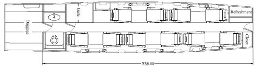
13 Fuselage Shape Planform Layout Cabin Dimensions The figure below shows a generic fuselage shape for a transport aircraft. The geometry is often divided into three parts: a tapered nose section in which the crew and various electronic components are housed, a constant section that contains the passenger cabin, and a mildly tapered tail cone. Note that passengers or other payload may extend over more than just the constant section, especially when the fuselage diameter is large. Because of the long tail cone sections, the pressurized payload section often extends back into this region. Additional area is required for lavatories, galleys, closets, and flight attendant seats. The number of lavatories depends on the number of passengers, with about 40 passengers per lavatory, a typical value. One must allow at least 34" x 38" for a standard lavatory. Closets take from a minimum 3/4" per passenger in economy class to 2" per first class passenger. Room for food service also depends on the airline operation, but even on 500 mi stage lengths, this can dictate as much as 1.5" of galley cabinet
14 length per passenger. Attendant seats are required adjacent to door exits and may be stowed upright, but clear of exit paths. In addition, emergency exits must include clear aisles that may increase the overall length of the fuselage. The requirements are described in the FAR's. On average the floor area per person ranges from 6.5 ft^2 for narrow body aircraft to 7.5 ft^2 for widebodies in an all-tourist configuration. A typical 3-class arrangement requires about 10 ft^2 per person. The figures below show two layouts for the 717. Note the fuselage nose and tailcone shapes. Two-Class 717 configuration with 8 first-class seats with 36" pitch and 98 coach seats with 32" pitch. Single-class 717 configuration with 117 seats at 32" and 31" pitch. In addition to providing space for seats, galleys, lavatories, and emergency exits as set by regulations, the aircraft layout is important for maintainence and studies are done early in the program to determine that
15 the layout is compatible with required ground services. Aerodynamics The fuselage shape must be such that separation and shock waves are avoided when possible. This requires that the nose and tail cone fineness ratios be sufficiently large so that excessive flow accelerations are avoided. Figure 2 shows the limit on nose fineness ratio set by the requirement for low wave drag on the nose.
16 Even when the Mach number is low, constraints on fuselage pressure gradients limit nose fineness ratios to values above about 1.5. The tail cone taper is chosen based on similar considerations and generally falls in the range of 1.8 to 2.0. The details of fuselage shaping may be determined by looking at the pressure distributions.
17 Several rules result from these analyses: The transition from nose to constant section, and constant section to tail cone should be smooth - free of discontinuities in slope (kinks). The tail cone slopes should resemble those shown in the examples. That is, the slope must change smoothly and the trailing edge should not be blunt. The closure angle near the aft end should not be too large (half angle less than ). Considerations Related to Fuselage Side-View The shape of the fuselage in side view is determined based on visibility requirements for the cockpit and ground clearance of the tail cone. Usually aft-fuselage upsweep is required to provide the capability of rotating to high angles of attack on the ground (often about 14 ). The upsweep cannot be set without estimating the length of the main gear, but this can be done early in the design process by comparison with similar aircraft.
18 Exercise 3: Fuselage Top View Enter fuselage seating parameters. About the input variables: Number of Seats: The total number of seats to be included at the specifed effective pitch. Seat Pitch: The average longitudinal distance between seats. This drawing includes only a single seat pitch, while most aircraft will be divided into 2 or 3 classes with rather different seat pitch. Use an efgfective value that produces the correct cabin length. Nose Fineness: The ratio of nose length to maximum diameter. The nose section is defined as the section that extends from the forwardmost point on the aircraft to the maximum diameter section. Tailcone Fineness: The ratio of tailcone length to maximum diameter. The tailcone section is defined as the section the end of the constant section to the aft end of the fuselage. Forward Extra Space: The distance (in feet for now) from the start of the constant section to the first row of seats. This parameter is used to add extra space for galleys or closests, or may be made negative if seats extend into the "nose" section of the fuselage. Aft Extra Space: The distance (in feet for now) from the end of the constant section to the last row of seats. This parameter is used to add extra space for galleys or closests, or may be made negative if seats extend into the tailcone section of the fuselage. The layout is based on the cross-section geometry specified in exercise 2.
19 Fuselage and Seating-Related FARs FAA Regulations Affecting Fuselage Design A number of federal regulations have a major effect on the fuselage layout and sizing. Included here are links to portions of FAR Part 25 that influence fuselage design. Seating-Related Items Emergency Egress Emergency Demonstration
20 FARs Related to Seating Sec Width of aisle. The passenger aisle width at any point between seats must equal or exceed the values in the following table: Sec Maximum number of seats abreast. Minimum passenger aisle width (inches) Less 25 in. than and Passenger 25 in. more seating from from capacity floor floor 10 or less /1/ through or more /1/ A narrower width not less than 9 inches may be approved when substantiated by tests found necessary by the Administrator. On airplanes having only one passenger aisle, no more than three seats abreast may be placed on each side of the aisle in any one row. Sec Doors. (a) Each cabin must have at least one easily accessible external door. (b) There must be a means to lock and safeguard each external door against opening in flight (either inadvertently by persons or as a result of mechanical failure or failure of a single structural element either during or after closure). Each external door must be openable from both the inside and the outside, even
21 though persons may be crowded against the door on the inside of the airplane. Inward opening doors may be used if there are means to prevent occupants from crowding against the door to an extent that would interfere with the opening of the door. The means of opening must be simple and obvious and must be arranged and marked so that it can be readily located and operated, even in darkness. Auxiliary locking devices may be used. (c) Each external door must be reasonably free from jamming as a result of fuselage deformation in a minor crash. (d) Each external door must be located where persons using them will not be endangered by the propellers when appropriate operating procedures are used. (e) There must be a provision for direct visual inspection of the locking mechanism to determine if external doors, for which the initial opening movement is not inward (including passenger, crew, service, and cargo doors), are fully closed and locked. The provision must be discernible under operational lighting conditions by appropriate crewmembers using a flashlight or equivalent lighting source. In addition, there must be a visual warning means to signal the appropriate flight crewmembers if any external door is not fully closed and locked. The means must be designed such that any failure or combination of failures that would result in an erroneous closed and locked indication is improbable for doors for which the initial opening movement is not inward. (f) External doors must have provisions to prevent the initiation of pressurization of the airplane to an unsafe level if the door is not fully closed and locked. In addition, it must be shown by safety analysis that inadvertent opening is extremely improbable. (g) Cargo and service doors not suitable for use as emergency exits need only meet paragraphs (e) and (f) of this section and be safeguarded against opening in flight as a result of mechanical failure or failure of a single structural element. (h) Each passenger entry door in the side of the fuselage must qualify as a Type A, Type I, or Type II passenger emergency exit and must meet the requirements of Secs through that apply to that type of passenger emergency exit. (i) If an integral stair is installed in a passenger entry door that is qualified as a passenger emergency exit, the stair must be designed so that under the following conditions the effectiveness of passenger emergency egress will not be impaired: (1) The door, integral stair, and operating mechanism have been subjected to the inertia forces specified in Sec (b)(3), acting separately relative to the surrounding structure. (2) The airplane is in the normal ground attitude and in each of the attitudes corresponding to collapse of one or more legs of the landing gear.
22 (j) All lavatory doors must be designed to preclude anyone from becoming trapped inside the lavatory, and if a locking mechanism is installed, it be capable of being unlocked from the outside without the aid of special tools. Sec Seats, berths, safety belts, and harnesses. (a) A seat (or berth for a nonambulant person) must be provided for each occupant who has reached his or her second birthday. (b) Each seat, berth, safety belt, harness, and adjacent part of the airplane at each station designated as occupiable during takeoff and landing must be designed so that a person making proper use of these facilities will not suffer serious injury in an emergency landing as a result of the inertia forces specified in Secs and (c) Each seat or berth must be approved. (d) Each occupant of a seat that makes more than an 18-degree angle with the vertical plane containing the airplane centerline must be protected from head injury by a safety belt and an energy absorbing rest that will support the arms, shoulders, head, and spine, or by a safety belt and shoulder harness that will prevent the head from contacting any injurious object. Each occupant of any other seat must be protected from head injury by a safety belt and, as appropriate to the type, location, and angle of facing of each seat, by one or more of the following: (1) A shoulder harness that will prevent the head from contacting any injurious object. (2) The elimination of any injurious object within striking radius of the head. (3) An energy absorbing rest that will support the arms, shoulders, head, and spine. (e) Each berth must be designed so that the forward part has a padded end board, canvas diaphragm, or equivalent means, that can withstand the static load reaction of the occupant when subjected to the forward inertia force specified in Sec Berths must be free from corners and protuberances likely to cause injury to a person occupying the berth during emergency conditions. (f) Each seat or berth, and its supporting structure, and each safety belt or harness and its anchorage must be designed for an occupant weight of 170 pounds, considering the maximum load factors, inertia forces, and reactions among the occupant, seat, safety belt, and harness for each relevant flight and ground load condition (including the emergency landing conditions prescribed in Sec ). In addition-- (1) The structural analysis and testing of the seats, berths, and their supporting structures may be determined by assuming that the critical load in the forward, sideward, downward, upward, and rearward
23 directions (as determined from the prescribed flight, ground, and emergency landing conditions) acts separately or using selected combinations of loads if the required strength in each specified direction is substantiated. The forward load factor need not be applied to safety belts for berths. (2) Each pilot seat must be designed for the reactions resulting from the application of the pilot forces prescribed in Sec (3) The inertia forces specified in Sec must be multiplied by a factor of 1.33 (instead of the fitting factor prescribed in Sec ) in determining the strength of the attachment of each seat to the structure and each belt or harness to the seat or structure. (g) Each seat at a flight deck station must have a restraint system consisting of a combined safety belt and shoulder harness with a single-point release that permits the flight deck occupant, when seated with the restraint system fastened, to perform all of the occupant's necessary flight deck functions. There must be a means to secure each combined restraint system when not in use to prevent interference with the operation of the airplane and with rapid egress in an emergency. (h) Each seat located in the passenger compartment and designated for use during takeoff and landing by a flight attendant required by the operating rules of this chapter must be: (1) Near a required floor level emergency exit, except that another location is acceptable if the emergency egress of passengers would be enhanced with that location. A flight attendant seat must be located adjacent to each Type A emergency exit. Other flight attendant seats must be evenly distributed among the required floor level emergency exits to the extent feasible. (2) To the extent possible, without compromising proximity to a required floor level emergency exit, located to provide a direct view of the cabin area for which the flight attendant is responsible. (3) Positioned so that the seat will not interfere with the use of a passageway or exit when the seat is not in use. (4) Located to minimize the probability that occupants would suffer injury by being struck by items dislodged from service areas, stowage compartments, or service equipment. (5) Either forward or rearward facing with an energy absorbing rest that is designed to support the arms, shoulders, head, and spine. (6) Equipped with a restraint system consisting of a combined safety belt and shoulder harness unit with a single point release. There must be means to secure each restraint system when not in use to prevent interference with rapid egress in an emergency. (i) Each safety belt must be equipped with a metal to metal latching device.
24 (j) If the seat backs do not provide a firm handhold, there must be a handgrip or rail along each aisle to enable persons to steady themselves while using the aisles in moderately rough air. (k) Each projecting object that would injure persons seated or moving about the airplane in normal flight must be padded. (l) Each forward observer's seat required by the operating rules must be shown to be suitable for use in conducting the necessary enroute inspection.
25 FARs Related to Emergency Evacuation Sec Ditching. (a) If certification with ditching provisions is requested, the airplane must meet the requirements of this section and Secs (e), , and (a). (b) Each practicable design measure, compatible with the general characteristics of the airplane, must be taken to minimize the probability that in an emergency landing on water, the behavior of the airplane would cause immediate injury to the occupants or would make it impossible for them to escape. (c) The probable behavior of the airplane in a water landing must be investigated by model tests or by comparison with airplanes of similar configuration for which the ditching characteristics are known. Scoops, flaps, projections, and any other factor likely to affect the hydrodynamic characteristics of the airplane, must be considered. (d) It must be shown that, under reasonably probable water conditions, the flotation time and trim of the airplane will allow the occupants to leave the airplane and enter the liferafts required by Sec If compliance with this provision is shown by buoyancy and trim computations, appropriate allowances must be made for probable structural damage and leakage. If the airplane has fuel tanks (with fuel jettisoning provisions) that can reasonably be expected to withstand a ditching without leakage, the jettisonable volume of fuel may be considered as buoyancy volume. (e) Unless the effects of the collapse of external doors and windows are accounted for in the investigation of the probable behavior of the airplane in a water landing (as prescribed in paragraphs (c) and (d) of this section), the external doors and windows must be designed to withstand the probable maximum local pressures. Sec Emergency evacuation. (a) Each crew and passenger area must have emergency means to allow rapid evacuation in crash landings, with the landing gear extended as well as with the landing gear retracted, considering the possibility of the airplane being on fire. (b) [Reserved] (c) For airplanes having a seating capacity of more than 44 passengers, it must be shown that the maximum seating capacity, including the number of crewmembers required by the operating rules for
26 which certification is requested, can be evacuated from the airplane to the ground under simulated emergency conditions within 90 seconds. Compliance with this requirement must be shown by actual demonstration using the test criteria outlined in appendix J of this part unless the Administrator finds that a combination of analysis and testing will provide data equivalent to that which would be obtained by actual demonstration. (d) [Reserved] (e) [Reserved] Sec Emergency exits. (a) Type. For the purpose of this part, the types of exits are defined as follows: (1) Type I. This type is a floor level exit with a rectangular opening of not less than 24 inches wide by 48 inches high, with corner radii not greater than one-third the width of the exit. (2) Type II. This type is a rectangular opening of not less than 20 inches wide by 44 inches high, with corner radii not greater than one-third the width of the exit. Type II exits must be floor level exits unless located over the wing, in which case they may not have a step-up inside the airplane of more than 10 inches nor a step-down outside the airplane of more than 17 inches. (3) Type III. This type is a rectangular opening of not less than 20 inches wide by 36 inches high, with corner radii not greater than one-third the width of the exit, and with a step-up inside the airplane of not more than 20 inches. If the exit is located over the wing, the step-down outside the airplane may not exceed 27 inches. (4) Type IV. This type is a rectangular opening of not less than 19 inches wide by 26 inches high, with corner radii not greater than one-third the width of the exit, located over the wing, with a step-up inside the airplane of not more than 29 inches and a step-down outside the airplane of not more than 36 inches. (5) Ventral. This type is an exit from the passenger compartment through the pressure shell and the bottom fuselage skin. The dimensions and physical configuration of this type of exit must allow at least the same rate of egress as a Type I exit with the airplane in the normal ground attitude, with landing gear extended. (6) Tail cone. This type is an aft exit from the passenger compartment through the pressure shell and through an openable cone of the fuselage aft of the pressure shell. The means of opening the tailcone must be simple and obvious and must employ a single operation. (7) Type A. This type is a floor level exit with a rectangular opening of not less than 42 inches wide by 72 inches high with corner radii not greater than one-sixth of the width of the exit.
27 (b) Step down distance. Step down distance, as used in this section, means the actual distance between the bottom of the required opening and a usable foot hold, extending out from the fuselage, that is large enough to be effective without searching by sight or feel. (c) Over-sized exits. Openings larger than those specified in this section, whether or not of rectangular shape, may be used if the specified rectangular opening can be inscribed within the opening and the base of the inscribed rectangular opening meets the specified step-up and step-down heights. (d) Passenger emergency exits. Except as provided in paragraphs (d) (3) through (7) of this section, the minimum number and type of passenger emergency exits is as follows: (1) For passenger seating configurations of 1 through 299 seats: Emergency exits for each side of the fuselage Passenger seating configuration (crewmember seats not Type Type Type Type included) I II III IV 1 through through through through through through through Additional exits are required for passenger seating configurations greater than 179 seats in accordance with the following table: Additional emergency exits (each side of fuselage) Increase in passenger seating configuration allowed
28 Type A 110 Type I 45 Type II 40 Type III 35 (2) For passenger seating configurations greater than 299 seats, each emergency exit in the side of the fuselage must be either a Type A or Type I. A passenger seating configuration of 110 seats is allowed for each pair of Type A exits and a passenger seating configuration of 45 seats is allowed for each pair of Type I exits. (3) If a passenger ventral or tail cone exit is installed and that exit provides at least the same rate of egress as a Type III exit with the airplane in the most adverse exit opening condition that would result from the collapse of one or more legs of the landing gear, an increase in the passenger seating configuration beyond the limits specified in paragraph (d) (1) or (2) of this section may be allowed as follows: (i) For a ventral exit, 12 additional passenger seats. (ii) For a tail cone exit incorporating a floor level opening of not less than 20 inches wide by 60 inches high, with corner radii not greater than one-third the width of the exit, in the pressure shell and incorporating an approved assist means in accordance with Sec (h), 25 additional passenger seats. (iii) For a tail cone exit incorporating an opening in the pressure shell which is at least equivalent to a Type III emergency exit with respect to dimensions, step-up and step-down distance, and with the top of the opening not less than 56 inches from the passenger compartment floor, 15 additional passenger seats. (4) For airplanes on which the vertical location of the wing does not allow the installation of overwing exits, an exit of at least the dimensions of a Type III exit must be installed instead of each Type IV exit required by subparagraph (1) of this paragraph. (5) An alternate emergency exit configuration may be approved in lieu of that specified in paragraph (d) (1) or (2) of this section provided the overall evacuation capability is shown to be equal to or greater than that of the specified emergency exit configuration. (6) The following must also meet the applicable emergency exit requirements of Secs through : (i) Each emergency exit in the passenger compartment in excess of the minimum number of required emergency exits. (ii) Any other floor level door or exit that is accessible from the passenger compartment and is as large or
29 larger than a Type II exit, but less than 46 inches wide. (iii) Any other passenger ventral or tail cone exit. (7) For an airplane that is required to have more than one passenger emergency exit for each side of the fuselage, no passenger emergency exit shall be more than 60 feet from any adjacent passenger emergency exit on the same side of the same deck of the fuselage, as measured parallel to the airplane's longitudinal axis between the nearest exit edges. (e) Ditching emergency exits for passengers. Ditching emergency exits must be provided in accordance with the following requirements whether or not certification with ditching provisions is requested: (1) For airplanes that have a passenger seating configuration of nine seats or less, excluding pilots seats, one exit above the waterline in each side of the airplane, meeting at least the dimensions of a Type IV exit. (2) For airplanes that have a passenger seating configuration of 10 seats or more, excluding pilots seats, one exit above the waterline in a side of the airplane, meeting at least the dimensions of a Type III exit for each unit (or part of a unit) of 35 passenger seats, but no less than two such exits in the passenger cabin, with one on each side of the airplane. The passenger seat/exit ratio may be increased through the use of larger exits, or other means, provided it is shown that the evacuation capability during ditching has been improved accordingly. (3) If it is impractical to locate side exits above the waterline, the side exits must be replaced by an equal number of readily accessible overhead hatches of not less than the dimensions of a Type III exit, except that for airplanes with a passenger configuration of 35 seats or less, excluding pilots seats, the two required Type III side exits need be replaced by only one overhead hatch. (f) Flightcrew emergency exits. For airplanes in which the proximity of passenger emergency exits to the flightcrew area does not offer a convenient and readily accessible means of evacuation of the flightcrew, and for all airplanes having a passenger seating capacity greater than 20, flightcrew exits shall be located in the flightcrew area. Such exits shall be of sufficient size and so located as to permit rapid evacuation by the crew. One exit shall be provided on each side of the airplane; or, alternatively, a top hatch shall be provided. Each exit must encompass an unobstructed rectangular opening of at least 19 by 20 inches unless satisfactory exit utility can be demonstrated by a typical crewmember. Sec Emergency exit arrangement. (a) Each emergency exit, including a flight crew emergency exit, must be a movable door or hatch in the external walls of the fuselage, allowing unobstructed opening to the outside. (b) Each emergency exit must be openable from the inside and the outside except that sliding window
30 emergency exits in the flight crew area need not be openable from the outside if other approved exits are convenient and readily accessible to the flight crew area. Each emergency exit must be capable of being opened, when there is no fuselage deformation-- (1) With the airplane in the normal ground attitude and in each of the attitudes corresponding to collapse of one or more legs of the landing gear; and (2) Within 10 seconds measured from the time when the opening means is actuated to the time when the exit is fully opened. (c) The means of opening emergency exits must be simple and obvious and may not require exceptional effort. Internal exit-opening means involving sequence operations (such as operation of two handles or latches or the release of safety catches) may be used for flight crew emergency exits if it can be reasonably established that these means are simple and obvious to crewmembers trained in their use. (d) If a single power-boost or single power-operated system is the primary system for operating more than one exit in an emergency, each exit must be capable of meeting the requirements of paragraph (b) of this section in the event of failure of the primary system. Manual operation of the exit (after failure of the primary system) is acceptable. (e) Each emergency exit must be shown by tests, or by a combination of analysis and tests, to meet the requirements of paragraphs (b) and (c) of this section. (f) There must be a means to lock each emergency exit and to safeguard against its opening in flight, either inadvertently by persons or as a result of mechanical failure. In addition, there must be a means for direct visual inspection of the locking mechanism by crewmembers to determine that each emergency exit, for which the initial opening movement is outward, is fully locked. (g) There must be provisions to minimize the probability of jamming of the emergency exits resulting from fuselage deformation in a minor crash landing. (h) When required by the operating rules for any large passenger-carrying turbojet-powered airplane, each ventral exit and tailcone exit must be-- (1) Designed and constructed so that it cannot be opened during flight; and (2) Marked with a placard readable from a distance of 30 inches and installed at a conspicuous location near the means of opening the exit, stating that the exit has been designed and constructed so that it cannot be opened during flight. Sec Emergency egress assist means and escape routes.
31 (a) Each nonoverwing landplane emergency exit more than 6 feet from the ground with the airplane on the ground and the landing gear extended and each nonoverwing Type A exit must have an approved means to assist the occupants in descending to the ground. (1) The assisting means for each passenger emergency exit must be a self- supporting slide or equivalent; and, in the case of a Type A exit, it must be capable of carrying simultaneously two parallel lines of evacuees. In addition, the assisting means must be designed to meet the following requirements: (i) It must be automatically deployed and deployment must begin during the interval between the time the exit opening means is actuated from inside the airplane and the time the exit is fully opened. However, each passenger emergency exit which is also a passenger entrance door or a service door must be provided with means to prevent deployment of the assisting means when it is opened from either the inside or the outside under nonemergency conditions for normal use. (ii) It must be automatically erected within 10 seconds after deployment is begun. (iii) It must be of such length after full deployment that the lower end is self-supporting on the ground and provides safe evacuation of occupants to the ground after collapse of one or more legs of the landing gear. (iv) It must have the capability, in 25-knot winds directed from the most critical angle, to deploy and, with the assistance of only one person, to remain usable after full deployment to evacuate occupants safely to the ground. (v) For each system installation (mockup or airplane installed), five consecutive deployment and inflation tests must be conducted (per exit) without failure, and at least three tests of each such five-test series must be conducted using a single representative sample of the device. The sample devices must be deployed and inflated by the system's primary means after being subjected to the inertia forces specified in Sec (b). If any part of the system fails or does not function properly during the required tests, the cause of the failure or malfunction must be corrected by positive means and after that, the full series of five consecutive deployment and inflation tests must be conducted without failure. (2) The assisting means for flightcrew emergency exits may be a rope or any other means demonstrated to be suitable for the purpose. If the assisting means is a rope, or an approved device equivalent to a rope, it must be-- (i) Attached to the fuselage structure at or above the top of the emergency exit opening, or, for a device at a pilot's emergency exit window, at another approved location if the stowed device, or its attachment, would reduce the pilot's view in flight; (ii) Able (with its attachment) to withstand a 400-pound static load.
32 (b) Assist means from the cabin to the wing are required for each Type A exit located above the wing and having a stepdown unless the exit without an assist means can be shown to have a rate of passenger egress at least equal to that of the same type of nonoverwing exit. If an assist means is required, it must be automatically deployed and automatically erected, concurrent with the opening of the exit and selfsupporting within 10 seconds. (c) An escape route must be established from each overwing emergency exit, and (except for flap surfaces suitable as slides) covered with a slip resistant surface. Except where a means for channeling the flow of evacuees is provided-- (1) The escape route must be at least 42 inches wide at Type A passenger emergency exits and must be at least 2 feet wide at all other passenger emergency exits, and (2) The escape route surface must have a reflectance of at least 80 percent, and must be defined by markings with a surface-to-marking contrast ratio of at least 5:1. (d) If the place on the airplane structure at which the escape route required in paragraph (c) of this section terminates, is more than 6 feet from the ground with the airplane on the ground and the landing gear extended, means to reach the ground must be provided to assist evacuees who have used the escape route. If the escape route is over a flap, the height of the terminal edge must be measured with the flap in the takeoff or landing position, whichever is higher from the ground. The assisting means must be usable and self-supporting with one or more landing gear legs collapsed and under a 25-knot wind directed from the most critical angle. The assisting means provided for each escape route leading from a Type A emergency exit must be capable of carrying simultaneously two parallel lines of evacuees. For other than Type A exits, the assist means must be capable of carrying simultaneously as many parallel lines of evacuees as there are required escape routes. Sec Emergency exit access. Each required emergency exit must be accessible to the passengers and located where it will afford an effective means of evacuation. Emergency exit distribution must be as uniform as practical, taking passenger distribution into account; however, the size and location of exits on both sides of the cabin need not be symmetrical. If only one floor level exit per side is prescribed, and the airplane does not have a tail cone or ventral emergency exit, the floor level exit must be in the rearward part of the passenger compartment, unless another location affords a more effective means of passenger evacuation. Where more than one floor level exit per side is prescribed, at least one floor level exit per side must be located near each end of the cabin, except that this provision does not apply to combination cargo/passenger configurations. In addition-- (a) There must be a passageway leading from the nearest main aisle to each Type I, Type II, or Type A emergency exit and between individual passenger areas. Each passageway leading to a Type A exit must be unobstructed and at least 36 inches wide. Passageways between individual passenger areas and those
33 leading to Type I and Type II emergency exits must be unobstructed and at least 20 inches wide. Unless there are two or more main aisles, each Type A exit must be located so that there is passenger flow along the main aisle to that exit from both the forward and aft directions. If two or more main aisles are provided, there must be unobstructed cross-aisles at least 20 inches wide between main aisles. There must be-- (1) A cross-aisle which leads directly to each passageway between the nearest main aisle and a Type A exit; and (2) A cross-aisle which leads to the immediate vicinity of each passageway between the nearest main aisle and a Type 1, Type II, or Type III exit; except that when two Type III exits are located within three passenger rows of each other, a single cross-aisle may be used if it leads to the vicinity between the passageways from the nearest main aisle to each exit. (b) Adequate space to allow crewmember(s) to assist in the evacuation of passengers must be provided as follows: (1) The assist space must not reduce the unobstructed width of the passageway below that required for the exit. (2) For each Type A exit, assist space must be provided at each side of the exit regardless of whether the exit is covered by Sec (a). (3) For any other type exit that is covered by Sec (a), space must at least be provided at one side of the passageway. (c) The following must be provided for each Type III or Type IV exit--(1) There must be access from the nearest aisle to each exit. In addition, for each Type III exit in an airplane that has a passenger seating configuration of 60 or more-- (i) Except as provided in paragraph (c)(1)(ii), the access must be provided by an unobstructed passageway that is at least 10 inches in width for interior arrangements in which the adjacent seat rows on the exit side of the aisle contain no more than two seats, or 20 inches in width for interior arrangements in which those rows contain three seats. The width of the passageway must be measured with adjacent seats adjusted to their most adverse position. The centerline of the required passageway width must not be displaced more than 5 inches horizontally from that of the exit. (ii) In lieu of one 10- or 20-inch passageway, there may be two passageways, between seat rows only, that must be at least 6 inches in width and lead to an unobstructed space adjacent to each exit. (Adjacent exits must not share a common passageway.) The width of the passageways must be measured with adjacent seats adjusted to their most adverse position. The unobstructed space adjacent to the exit must extend vertically from the floor to the ceiling (or bottom of sidewall stowage bins), inboard from the exit
34 for a distance not less than the width of the narrowest passenger seat installed on the airplane, and from the forward edge of the forward passageway to the aft edge of the aft passageway. The exit opening must be totally within the fore and aft bounds of the unobstructed space. (2) In addition to the access-- (i) For airplanes that have a passenger seating configuration of 20 or more, the projected opening of the exit provided must not be obstructed and there must be no interference in opening the exit by seats, berths, or other protrusions (including any seatback in the most adverse position) for a distance from that exit not less than the width of the narrowest passenger seat installed on the airplane. (ii) For airplanes that have a passenger seating configuration of 19 or fewer, there may be minor obstructions in this region, if there are compensating factors to maintain the effectiveness of the exit. (3) For each Type III exit, regardless of the passenger capacity of the airplane in which it is installed, there must be placards that-- (i) Are readable by all persons seated adjacent to and facing a passageway to the exit; (ii) Accurately state or illustrate the proper method of opening the exit, including the use of handholds; and (iii) If the exit is a removable hatch, state the weight of the hatch and indicate an appropriate location to place the hatch after removal. (d) If it is necessary to pass through a passageway between passenger compartments to reach any required emergency exit from any seat in the passenger cabin, the passageway must be unobstructed. However, curtains may be used if they allow free entry through the passageway. (e) No door may be installed in any partition between passenger compartments. (f) If it is necessary to pass through a doorway separating the passenger cabin from other areas to reach any required emergency exit from any passenger seat, the door must have a means to latch it in open position. The latching means must be able to withstand the loads imposed upon it when the door is subjected to the ultimate inertia forces, relative to the surrounding structure, listed in Sec (b).
35 FARs Related to Evacuation Demonstration FAR Part 25, Appendix J: Emergency Evacuation Demonstration The following test criteria and procedures must be used for showing compliance with Sec : (a) The emergency evacuation must be conducted either during the dark of the night or during daylight with the dark of night simulated. If the demonstration is conducted indoors during daylight hours, it must be conducted with each window covered and each door closed to minimize the daylight effect. Illumination on the floor or ground may be used, but it must be kept low and shielded against shining into the airplane's windows or doors. (b) The airplane must be in a normal attitude with landing gear extended. (c) Unless the airplane is equipped with an off-wing descent means, stands or ramps may be used for descent from the wing to the ground. Safety equipment such as mats or inverted life rafts may be placed on the floor or ground to protect participants. No other equipment that is not part of the emergency evacuation equipment of the airplane may be used to aid the participants in reaching the ground. (d) Except as provided in paragraph (a) of this Appendix, only the airplane's emergency lighting system may provide illumination. (e) All emergency equipment required for the planned operation of the airplane must be installed. (f) Each external door and exit, and each internal door or curtain, must be in the takeoff configuration. (g) Each crewmember must be seated in the normally assigned seat for takeoff and must remain in the seat until receiving the signal for commencement of the demonstration. Each crewmember must be a person having knowledge of the operation of exits and emergency equipment and, if compliance with Sec is also being demonstrated, each flight attendant must be a member of a regularly scheduled line crew. (h) A representative passenger load of persons in normal health must be used as follows:
36 (1) At least 40 percent of the passenger load must be female. (2) At least 35 percent of the passenger load must be over 50 years of age. (3) At least 15 percent of the passenger load must be female and over 50years of age. (4) Three life-size dolls, not included as part of the total passenger load, must be carried by passengers to simulate live infants 2 years old or younger. (5) Crewmembers, mechanics, and training personnel, who maintain or operate the airplane in the normal course of their duties, may not be used as passengers. (i) No passenger may be assigned a specific seat except as the Administrator may require. Except as required by subparagraph (g) of this paragraph, no employee of the applicant may be seated next to an emergency exit. (j) Seat belts and shoulder harnesses (as required) must be fastened. (k) Before the start of the demonstration, approximately one-half of the total average amount of carry-on baggage, blankets, pillows, and other similar articles must be distributed at several locations in aisles and emergency exit access ways to create minor obstructions. (l) No prior indication may be given to any crewmember or passenger of the particular exits to be used in the demonstration. (m) The applicant may not practice, rehearse, or describe the demonstration for the participants nor may any participant have taken part in this type of demonstration within the preceding 6 months. (n) The pre-takeoff passenger briefing required by Sec may be given. The passengers may also be advised to follow directions of crewmembers but not be instructed on the procedures to be followed in the demonstration. (o) If safety equipment as allowed by paragraph (c) of this appendix is provided, either all passenger and cockpit windows must be blacked out or all of the emergency exits must have safety equipment in order to prevent disclosure of the available emergency exits. (p) Not more than 50 percent of the emergency exits in the sides of the fuselage of an airplane that meets all of the requirements applicable to the required emergency exits for that airplane may be used for the demonstration. Exits that are not to be used in the demonstration must have the exit handle deactivated or must be indicated by red lights, red tape, or other acceptable means placed outside the exits to indicate fire or other reason why they are unusable. The exits to be used must be representative of all of the emergency exits on the airplane and must be designated by the applicant, subject to approval by the Administrator. At least one floor level exit must be used. (q) Except as provided in paragraph (c) of this section, all evacuees must leave the airplane by a means
37 provided as part of the airplane's equipment. (r) The applicant's approved procedures must be fully utilized, except the flight crew must take no active role in assisting others inside the cabin during the demonstration. (s) The evacuation time period is completed when the last occupant has evacuated the airplane and is on the ground. Provided that the acceptance rate of the stand or ramp is no greater than the acceptance rate of the means available on the airplane for descent from the wing during an actual crash situation, evacuees using stands or ramps allowed by paragraph (c) of this Appendix are considered to be on the ground when they are on the stand or ramp.

38 Additional Considerations for Supersonic Aircraft Additional Considerations for Supersonic Aircraft At supersonic speeds the shape and dimensions of the fuselage have a strong effect on the aircraft drag. Supersonic wave drag increases quickly as the fuselage volume increases and the fineness ratio is reduced. For this reason, the cabin diameter is kept as small as possible and the cabin length increased. The figure below shows a Aerospatiale design for the fuselage of a Mach 2.0 transport (Avion de Transport Supersonique Futur, ATSF). Note that the diameter and seat layout is similar to the MD-80, but the fuselage is much longer. The Concorde diameter of 113 inches is very small because of the strong impact of fuselage diameter on wave drag. The requirement for a high overall fineness ratio is reflected in the fuselage geometries shown below.
39 For comparison, a Boeing design for a high speed civil transport is shown below. Note that the Boeing design has a fuselage whose diameter varies over the cabin section. This is done to reduce

40 the interference wave drag between wing and fuselage. This was not done on the Concorde as it was felt that the increase in production costs would be too high. Indeed the variable cross-section introduces many difficulties and affects the seating arrangement as shown below. The supersonic business jet represents a somewhat less ambitious entry into commercial supersonic flight. Since supersonic wave drag depends on volume, the motivation for a smaller cabin cross-section is greater, and high fineness ratios are required. The drawings below illustrate the fuselage and cabin design for a supersonic business jet by Reno Aeronautical Corporation.
41
Part 26 CAA Consolidation 25 March 2010 Additional Airworthiness Requirements
 Part 26 CAA Consolidation 25 March 2010 Additional Airworthiness Requirements Published by the Civil Aviation Authority of New Zealand DESCRIPTION Part 26 prescribes rules for airworthiness requirements
PLANE PAL August 2017
 PLANE PAL August 2017 REF AIR17-10 PLANE PAL Aviation Impact Study. 1. Executive Summary. Plane Pal is an inflatable mattress that is carried onto the aircraft by passengers to extend the base of a seat
Comment response document for Airbus A380 D 04 Crew Rest Compartment
 Comment response document for Airbus A380 D 04 Crew Rest Compartment # Commenter Comment EASA position 1 Boeing Specific section of concern Background a. Identification of issue Airbus offer in option
Content of Description
 APPENDIX B : DESCRIPTION OF FLIGHT ATTENDANT PRACTICAL TEST STANDARD PTS 8081-11 Content of Description 1. OBJECTIVE OF FLIGHT ATTENDANT PRACTICAL TEST. 2. FLIGHT ATTENDANT PRACTICAL TEST AREAS. I. PREFLIGHT
Part 137. Agricultural Aircraft Operations. CAA Consolidation. 10 March Published by the Civil Aviation Authority of New Zealand
 Part 137 CAA Consolidation 10 March 2017 Agricultural Aircraft Operations Published by the Civil Aviation Authority of New Zealand DESCRIPTION Part 137 prescribes rules, that are additional to and exceptions
ORDER TCAA-O-OPS014B March 2013
 ORDER TCAA-O-OPS014B March 2013 EMERGENCY EVACUATION AND DITCHING DEMONSTRATIONS 1.0 PURPOSE This Order provides direction and guidance to inspectors for planning, observing, and evaluating emergency evacuation
6. CARRY-ON BAGGAGE CONTROL PROGRAM
 6. CARRY-ON BAGGAGE CONTROL PROGRAM 6.1 Corporate Policy The Helijet Safety Policy is designed to ensure an organizational and cultural framework that complies with regulations governing the operation
Special Conditions: The Boeing Company Model and Airplanes;
 This document is scheduled to be published in the Federal Register on 05/18/2018 and available online at https://federalregister.gov/d/2018-10576, and on FDsys.gov [4910-13] DEPARTMENT OF TRANSPORTATION
EASA Safety Information Bulletin
 EASA Safety Information Bulletin EASA SIB No: 2014-29 SIB No.: 2014-29 Issued: 24 October 2014 Subject: Minimum Cabin Crew for Twin Aisle Aeroplanes Ref. Publications: Commission Regulation (EU) No 965/2012
Glossary. basic empty weight (GAMA). Standard empty weight plus optional equipment.
. Standard empty weight plus optional equipment.") Glossary General Aviation Manufacturers Association (GAMA) 14 CFR, Part 121. The Federal regulations governing domestic, flag, and supplemental operations. 14 CFR, Part 135. The Federal regulations governing
Glossary General Aviation Manufacturers Association (GAMA) 14 CFR, Part 121. The Federal regulations governing domestic, flag, and supplemental operations. 14 CFR, Part 135. The Federal regulations governing
(ii) Weight. Maximum gross weight for all tests, except where otherwise described in subparagraph (iii) below.
 Weight. Maximum gross weight for all tests, except where otherwise described in subparagraph (iii) below.") (2) Analysis of System. An analysis of the control system should be completed before conducting the loss of the primary lateral control test. On some airplanes, the required single lateral control system
(2) Analysis of System. An analysis of the control system should be completed before conducting the loss of the primary lateral control test. On some airplanes, the required single lateral control system
DEPARTMENT OF TRANSPORTATION FEDERAL AVIATION ADMINISTRATION TYPE CERTIFICATE DATA SHEET A2NM
 DEPARTMENT OF TRANSPORTATION FEDERAL AVIATION ADMINISTRATION A2NM Revision 15 BOEING 757-200 Series 757-200PF Series 757-200CB Series September 1, 1998 TYPE CERTIFICATE DATA SHEET A2NM This data sheet,
FLIGHT AND OPERATING MANUAL SUPPLEMENT FMS305902, REVISION 1 SEAPLANES WEST INC.
 FLIGHT AND OPERATING MANUAL SUPPLEMENT FMS305902, REVISION 1 AEROCET 3500/3500L FLOAT INSTALLATION ON CESSNA 182E THROUGH 182N AIRCRAFT AIRCRAFT MODEL: AIRCRAFT REGISTRATION: AIRCRAFT SERIAL NUMBER: TRANSPORT
717 Aeroplane JAA Data Sheet
 The Following Content of this Data Sheet is Complete In Accordance With the Concurrent and Cooperative Certification Process (CCC) Working Procedure, Draft Issue 8 dated 17-May-1994 and JAA Administrative
2.1 General Characteristics. 2.2 General Dimensions. 2.3 Ground Clearances. 2.4 Interior Arrangements. 2.5 Cabin Cross Sections
 2.0 AIRPLANE DESCRIPTION 2.1 General Characteristics 2.2 General Dimensions 2.3 Ground Clearances 2.4 Interior Arrangements 2.5 Cabin Cross Sections 2.6 Lower Cargo Compartments 2.7 Door Clearances JUNE
National Standard for Tonnage Measurement and Calculation of the Vessels Engaged on International Voyages General Definitions 2.
 National Standard for Tonnage Measurement and Calculation of the Vessels Engaged on International Voyages General 1. (1) The tonnage of a ship shall consist of gross tonnage and net tonnage. (2) The gross
Chapter 6 Fuselage and tail sizing (Lectures 23 to 30)
") Chapter 6 Fuselage and tail sizing (Lectures 23 to 30) Keywords: Features of the fuselages of general aviation aircraft and transport airplanes ; desired features of fuselage design; guidelines for sizing
Chapter 6 Fuselage and tail sizing (Lectures 23 to 30) Keywords: Features of the fuselages of general aviation aircraft and transport airplanes ; desired features of fuselage design; guidelines for sizing
Chapter 5 Center of Gravity Change After Repair or Alteration
 Chapter 5 Center of Gravity Change After Repair or Alteration The largest weight changes that occur during the lifetime of an aircraft are those caused by alterations and repairs. It is the responsibility
Certification Memorandum. Regulatory Significant Standards Differences for pair CS-25 Amendment 12 vs 14 CFR Part 25 Amendment 1 through 136
 Certification Memorandum Regulatory Significant Standards Differences for pair CS-25 Amendment 12 vs 14 CFR Part 25 Amendment 1 through 136 issued 19 August 2015 Regulatory requirement(s): CS-25, Technical
Transportation Engineering -II Dr. Rajat Rastogi Department of Civil Engineering Indian Institute of Technology - Roorkee
 Transportation Engineering -II Dr. Rajat Rastogi Department of Civil Engineering Indian Institute of Technology - Roorkee Lecture - 36 Aprons & Aircraft Parking Dear students, today s lecture we are going
Tents & Membrane Structures Information Packet
 Tents & Membrane Structures Information Packet South Metro Fire Rescue Authority Community Safety Services Division Life Safety Bureau 9195 E. Mineral Ave. Centennial, Colorado 80112 Tel: (720) 989-2230
ADVISORY CIRCULAR CAA-AC-OPS007A
 ADVISORY CIRCULAR CAA-AC-OPS007A July 2008 PASSENGER SAFETY INFORMATION BRIEFING AND BRIEFING CARDS 1.0 PURPOSE This Advisory Circular (AC) provides information about the items that are required to be,
European Aviation Safety Agency
 Page 1/7 European Aviation Safety Agency EASA SUPPLEMENTAL TYPE-CERTIFICATE DATA SHEET IAI/Bedek Aviation Group Boeing 767-300 Special Freighter Conversion (EASA STC:10028430 Revision 1) Aircraft Manufacturer:
Runway Length Analysis Prescott Municipal Airport
 APPENDIX 2 Runway Length Analysis Prescott Municipal Airport May 11, 2009 Version 2 (draft) Table of Contents Introduction... 1-1 Section 1 Purpose & Need... 1-2 Section 2 Design Standards...1-3 Section
HARD. Preventing. Nosegear Touchdowns
 Preventing HARD Nosegear Touchdowns In recent years, there has been an increase in the incidence of significant structural damage to commercial airplanes from hard nosegear touchdowns. In most cases, the
Easy Access Rules for Additional Airworthiness Specifications (Regulation (EU) No 2015/640)
 No 2015/640)") Easy Access Rules for Additional Airworthiness Specifications (Regulation (EU) No 2015/640) EASA erules: aviation rules for the 21st century Rules and regulations are the core of the European Union civil
Easy Access Rules for Additional Airworthiness Specifications (Regulation (EU) No 2015/640) EASA erules: aviation rules for the 21st century Rules and regulations are the core of the European Union civil
DGAC Costa Rica. MCAR OPS 1-Subpart Q LIMITATIONS OF FLIGHT TIME AND TIME OF SERVICE AND REST REQUIREMENTS. 30-June-2009
 DGAC Costa Rica MCAR OPS 1-Subpart Q LIMITATIONS OF FLIGHT TIME AND TIME OF SERVICE AND REST REQUIREMENTS 30-June-2009 Contents Contents... 2 SUBPART Q LIMITATIONS OF FLIGHT TIME AND TIME OF SERVICE AND
FORT LAUDERDALE-HOLLYWOOD INTERNATIONAL AIRPORT ENVIRONMENTAL IMPACT STATEMENT DRAFT
 D.3 RUNWAY LENGTH ANALYSIS Appendix D Purpose and Need THIS PAGE INTENTIONALLY LEFT BLANK Appendix D Purpose and Need APPENDIX D.3 AIRFIELD GEOMETRIC REQUIREMENTS This information provided in this appendix
Osceola County Department of Fire Rescue and Emergency Medical Services
 1. Authority Osceola County Department of Fire Rescue and TENT STANDARD This Standard operates under the authority of Osceola County, Florida Ordinance and State Statutes. 1.1 Scope This standard covers
Marin County Fire Department. Fire Protection Standard 119. Tents and Awnings
 Page: 1 7 Scope: These standards shall apply to any temporary membrane structure, tent, or canopy, in accordance with the California Code Regulations (CCR) Title 19 and California Fire Code (CFC). Temporary
FAA Requirements for Engine-out Procedures and Obstacle Clearance
 FAA Requirements for Engine-out Procedures and Obstacle Clearance Presentation to: CAAC Engine-out Procedures Seminar Name: Chuck Friesenhahn Date: 11/29/2005 Flight Standards Senior Advisor, Advanced
AIRBUS FlyByWire How it really works
 AIRBUS FlyByWire How it really works Comparison between APOLLO s and Phoenix PSS Airbus FlyByWire implementation for FS2002 Copyright by APOLLO Software Publishing The FlyByWire control implemented on
Wing Taper Ratio. Wing Incidence. Wing Incidence
 Wing Design II Lift surfaces/devices Control surfaces Ailerons Leading-edge slats Vertical Stabilizer Rudder Spoilers Elevators Flaps Horizontal Stabilizer Wing Wing-tip device Basic Configuration Choices
TYPE CERTIFICATE DATA SHEET A3WE
 DEPARTMENT OF TRANSPORTATION FEDERAL AVIATION ADMINISTRATION A3WE Revision 19 BOEING 727 Series 727-100 Series 727C Series 727-100C Series 727-200 Series 727-200F Series February 20, 1991 TYPE CERTIFICATE
Airworthiness Directive Schedule
 Airworthiness Directive Schedule Aeroplanes 27 October 2011 Notes 1. This AD schedule is applicable to Piper PA-42-1000 (Cheyenne 400LS) aircraft manufactured under Federal Aviation Administration (FAA)
SECTION B AIRWORTHINESS CERTIFICATION
 SECTION B AIRWORTHINESS CERTIFICATION 1 2 NEPALESE CIVIL AIRWORTHINESS REQUIREMENTS SECTION B AIRWORTHINESS CERTIFICATION CHAPTER B.1 ISSUE 4 JANUARY 2009 1. INTRODUCTION TYPE CERTIFICATES 1.1 Before a
NOTE: DATA PRELIMINARY
 2.0 AIRPLANE DESCRIPTION 2.1 General Characteristics 2.2 General Dimensions 2.3 Ground Clearances 2.4 Interior Arrangements 2.5 Cabin Cross Sections 2.6 Lower Cargo Compartments 2.7 Door Clearances REV
PROPOSED HORIZONTAL LAYOUT FILLET DESIGN FOR ENTRANCE/EXIT TAXIWAYS
 PROPOSED HORIZONTAL LAYOUT FILLET DESIGN FOR ENTRANCE/EXIT TAXIWAYS INTRODUCTION The Zelienople Airport Authority (ZAA) has commenced engineering activities for the rehabilitation of Runway 17-35 to a
Worldwide Aircraft Services, Inc
 Worldwide Aircraft Services, Inc Worldwide Aircraft Services, Inc. Springfield / Branson Regional Airport 2755 N. General Aviation Ave., Springfield, Missouri 65803 (417) 865-1879 # 0r Fax (417) 865-6884
FINAL REPORT AIRBUS A380, REGISTRATION 9V-SKJ TURBULENCE EVENT. 18 October 2014
 FINAL REPORT AIRBUS A380, REGISTRATION 9V-SKJ TURBULENCE EVENT 18 October 2014 AIB/AAI/CAS.108 Air Accident Investigation Bureau of Singapore Ministry of Transport Singapore 27 May 2016 The Air Accident
Advisory Circular (AC)
") Advisory Circular (AC) Certification of Transport Category Aeroplanes On Narrow Runways File No. 5009-6-525 AC No. 525-014 RDIMS No. 528471-V3 Issue No. 01 Issuing Branch Aircraft Certification Effective
Advisory Circular (AC) Certification of Transport Category Aeroplanes On Narrow Runways File No. 5009-6-525 AC No. 525-014 RDIMS No. 528471-V3 Issue No. 01 Issuing Branch Aircraft Certification Effective
NOISE ABATEMENT PROCEDURES
 1. Introduction NOISE ABATEMENT PROCEDURES Many airports today impose restrictions on aircraft movements. These include: Curfew time Maximum permitted noise levels Noise surcharges Engine run up restrictions
Accident Prevention Program
 Accident Prevention Program WEIGHT AND BALANCE An Important Safety Consideration for Pilots Aircraft performance and handling characteristics are affected by the gross weight and center of gravity limits.
SECTION 6 - SEPARATION STANDARDS
 SECTION 6 - SEPARATION STANDARDS CHAPTER 1 - PROVISION OF STANDARD SEPARATION 1.1 Standard vertical or horizontal separation shall be provided between: a) All flights in Class A airspace. b) IFR flights
airplane has a novel or unusual design feature associated with side-facing, oblique seats. The
 This document is scheduled to be published in the Federal Register on 04/28/2015 and available online at http://federalregister.gov/a/2015-09784, and on FDsys.gov [4910-13] DEPARTMENT OF TRANSPORTATION
A Human Factors Approach to Preventing Tail Strikes. Captain Vern Jeremica Senior Safety Pilot Boeing Commercial Airplanes May 2004
 A Human Factors Approach to Preventing Tail Strikes Captain Vern Jeremica Senior Safety Pilot Boeing Commercial Airplanes May 2004 1 Presentation Overview Tail strike statistics as of 2003 Engineering/procedural
ATR FREIGHTER VERSIONS. AN EASY CONVERSION AVAILABLE SINCE 2002, TO EXTEND ATR s
 ATR FREIGHTER VERSIONS AN EASY CONVERSION AVAILABLE SINCE 2002, TO EXTEND ATR s economic advantages to the cargo market ATR FREIGHTER CONVERSION AN ADAPTED PLATFORM FOR EASY FREIGHTER CONVERSION XXXXXXXXXXXXXXXXXX
American Airlines Next Top Model
 Page 1 of 12 American Airlines Next Top Model Introduction Airlines employ several distinct strategies for the boarding and deboarding of airplanes in an attempt to minimize the time each plane spends
FOR REFERENCE ONLY NOT FOR FLIGHT
 PIPER AIRCRAFT CORPORATION SECTION 6 6.7 GENERAL LOADING RECOMMENDATIONS For all airplane configurations, it is the responsibility of the pilot in command to make sure that the airplane always remains
The following criteria shall be applied within the boundaries of the AO District:
 Sec. 419 (a) Purpose AIRPORT OVERLAY DISTRICT (AO) The purpose of the Airport Overlay District is to regulate and restrict the height of structures, objects, or natural growth, regulate the locations of
SUNY GENESEO ENVIRONMENTAL HEALTH AND SAFETY
 Prepared by: Chuck Reyes Page 1 of 6 PURPOSE SUNY Geneseo strives to keep all students, staff and visitors safe while at our campus. To that end, we have summarized requirements for tents and canopies,
GCAA ADVISORY CIRCULAR
 GUYANA CIVIL AVIATION AUTHORITY 73 High Street Kingston Georgetown GUYANA TEL. NOs: (592) 225 6822, 225 0778, 227 8111 FAX: (592) 225 6800 E-mail: director-general@gcaa-gy.org GCAA ADVISORY CIRCULAR AERODROME
CESSNA CITATION IIB PW JT15D-4 INTRODUCTION. Runway Analysis provides the means to determine maximum allowable takeoff and landing weights based upon:
 CESSNA CITATION IIB PW JT15D-4 INTRODUCTION Runway Analysis provides the means to determine maximum allowable takeoff and landing weights based upon: Airport characteristics consisting of airport elevation,
767 Airplane Characteristics for. Airport Planning. Boeing Commercial Airplanes. D SEPTEMBER 2005 i
 767 Airplane Characteristics for Airport Planning Boeing Commercial Airplanes SEPTEMBER 2005 i 767 AIRPLANE CHARACTERISTICS FOR AIRPORT PLANNING LIST OF ACTIVE PAGES Page Date Page Date Page Date Original
Federal Aviation Regulations (including accident reporting, TSA security and light sport)
") Federal Aviation Regulations (including accident reporting, TSA security and light sport) 39.7 Airworthiness Directives There is a repetitive AD on your glider (i.e., Schweizer tow hook inspection). What
Federal Aviation Regulations (including accident reporting, TSA security and light sport) 39.7 Airworthiness Directives There is a repetitive AD on your glider (i.e., Schweizer tow hook inspection). What
New Engine Option (A330neo) airplanes. These airplanes will have a novel or unusual design
 airplanes. These airplanes will have a novel or unusual design") This document is scheduled to be published in the Federal Register on 01/16/2018 and available online at https://federalregister.gov/d/2018-00546, and on FDsys.gov [4910-13] DEPARTMENT OF TRANSPORTATION
This document is scheduled to be published in the Federal Register on 01/16/2018 and available online at https://federalregister.gov/d/2018-00546, and on FDsys.gov [4910-13] DEPARTMENT OF TRANSPORTATION
modification to the Cirrus Model SR22 airplane. This airplane as modified by Tamarack will
 This document is scheduled to be published in the Federal Register on 05/15/2012 and available online at http://federalregister.gov/a/2012-11214, and on FDsys.gov [4910-13] DEPARTMENT OF TRANSPORTATION
All-Weather Operations Training Programme
 GOVERNMENT OF INDIA CIVIL AVIATION DEPARTMENT DIRECTOR GENERAL OF CIVIL AVIATION OC NO 3 OF 2014 Date: OPERATIONS CIRCULAR Subject: All-Weather Operations Training Programme 1. INTRODUCTION In order to
TENTS, CANOPIES AND TEMPORARY MEMBRANE STRUCTURES
 INFORMATION BULLETIN TENTS, CANOPIES AND TEMPORARY MEMBRANE STRUCTURES Code Reference: Title 19 California Code of Regulations California Fire Code (CFC), 2001 Edition, Article 32 California Building Code
CHAPTER 22 WEIGHT CONTROL OF AIRCRAFT
 May 2016 Page 1 of 8 CHAPTER 22 WEIGHT CONTROL OF AIRCRAFT 1. Introduction 1.1. The mass and centre of gravity of aircraft should be determined prior to the initial issuance of the Certificate of Airworthiness.
Special Conditions: Cranfield Aerospace Limited, Cessna Aircraft Company Model 525;
 This document is scheduled to be published in the Federal Register on 01/05/2017 and available online at https://federalregister.gov/d/2016-31819, and on FDsys.gov [4910-13] DEPARTMENT OF TRANSPORTATION
Consideration will be given to other methods of compliance which may be presented to the Authority.
 Advisory Circular AC 139-10 Revision 1 Control of Obstacles 27 April 2007 General Civil Aviation Authority advisory circulars (AC) contain information about standards, practices and procedures that the
CHAPTER 5 SEPARATION METHODS AND MINIMA
 CHAPTER 5 SEPARATION METHODS AND MINIMA 5.1 Provision for the separation of controlled traffic 5.1.1 Vertical or horizontal separation shall be provided: a) between IFR flights in Class D and E airspaces
Step by Step Set Up Guide
 lite Step by Step Set Up Guide 1 lifting lug Secure lifting lugs to a certified lifting sling. Stand and stabilize escape system under work platform. Position module with round lunette ring facing work
APPENDIX D FEDERAL AVIATION REGULATIONS, PART 77
 APPENDIX D FEDERAL AVIATION REGULATIONS, PART 77 Subparts A through C PART 77 - OBJECTS AFFECTING NAVIGABLE AIRSPACE Subpart A General 77.1 Scope. 77.2 Definition of terms. 77.3 Standards. 77.5 Kinds of
ECLIPSE 500. Aircraft Overview. Do Not Use For Flight
 ECLIPSE 500 Aircraft Overview Do Not Use For Flight 1. Aircraft Overview 1.1 General The Eclipse 500 is a twin-turbofan aircraft powered by two Pratt & Whitney Canada PW610F-A engines. It is a five- to
Valley Fliers 1402 Auburn Way North, #223 Auburn WA 98002
 Valley Fliers 1402 Auburn Way North, #223 Auburn WA 98002 Instructor: Check Out Date: Phase 1: Pre-Flight Name: Certificate Number: Certificate Type: Ratings: Total Flight Time: Last 90 Days: Club check
HONDURAS AGENCY of CIVIL AERONAUTICS (AHAC) RAC-OPS-1 SUBPART Q FLIGHT / DUTY TIME LIMITATIONS AND REST REQUIREMENTS. 01-Jun-2012
 RAC-OPS-1 SUBPART Q FLIGHT / DUTY TIME LIMITATIONS AND REST REQUIREMENTS. 01-Jun-2012") HONDURAS AGENCY of CIVIL AERONAUTICS (AHAC) RAC-OPS-1 SUBPART Q FLIGHT / DUTY TIME LIMITATIONS AND REST REQUIREMENTS 01-Jun-2012 Contents Contents... 2 RAC OPS.1.1080 General provisions... 3 RAC OPS.1.1085
HONDURAS AGENCY of CIVIL AERONAUTICS (AHAC) RAC-OPS-1 SUBPART Q FLIGHT / DUTY TIME LIMITATIONS AND REST REQUIREMENTS 01-Jun-2012 Contents Contents... 2 RAC OPS.1.1080 General provisions... 3 RAC OPS.1.1085
TYPES OF PASSENGERS WITH SPECIAL NEEDS. Passengers with reduced mobility. These in turn are divided into three categories:
 To make your trip as simple as possible, please tell us about your special needs at least 48 hours in advance. You can do it when you book, while you are purchasing your flight or by calling our Customer
Official Journal of the European Union L 296/125
 25.10.2012 Official Journal of the European Union L 296/125 SECTION 2 Helicopters CAT.IDE.H.100 Instruments and equipment general (a) Instruments and equipment required by this Subpart shall be approved
Boeing Aircraft and the Impact on Airports
 International Civil Aviation Organization on Pavement Management Systems Lima, Peru November 19-22, 2003 Boeing Aircraft and the Impact on Airports Orest Shepson Principal Engineer - Airport Technology
Flammability of Interior Materials
 TECHNICAL STANDARDS DOCUMENT No. 302, Revision 0R Flammability of Interior Materials The text of this document is based on Federal Motor Vehicle Safety Standard No. 302, Flammability of Interior Materials,
M/V. Tonnage Measurement (ITC-69) Tartous Naval Architect. Guardian Bureau of Shipping LLC Page 1 of 14 Form 5510/TM-69/GBS/DEL/01
 Tartous Naval Architect. Guardian Bureau of Shipping LLC Page 1 of 14 Form 5510/TM-69/GBS/DEL/01") M/V Tonnage Measurement (ITC-69) Tartous 2002-05-09 Naval Architect Guardian Bureau of Shipping LLC Page 1 of 14 Form 5510/TM-69/GBS/DEL/01 CONTENTS Ship s Specifications 3 A. International Conference
M/V Tonnage Measurement (ITC-69) Tartous 2002-05-09 Naval Architect Guardian Bureau of Shipping LLC Page 1 of 14 Form 5510/TM-69/GBS/DEL/01 CONTENTS Ship s Specifications 3 A. International Conference
Picnic Units A picnic unit is a part of a picnic area
 Grab Bars Grab bars are usually provided in buildings to provide stability and allow a person to use his or her arms to assist in movement over short distances. The most common location for grab bars is
The Boeing Next-Generation 737 Family Productive, Progressive, Flexible, Familiar
 Backgrounder Boeing Commercial Airplanes P.O. Box 3707 MC 21-70 Seattle, Washington 98124-2207 www.boeing.com The Boeing Next-Generation 737 Family Productive, Progressive, Flexible, Familiar The members
MODEL AERONAUTICAL ASSOCIATION OF AUSTRALIA
 MODEL AERONAUTICAL ASSOCIATION OF AUSTRALIA GENERAL RULES AND GUIDELINES FOR THE OPERATION OF MODEL AIRCRAFT MOP014 APPROVED: MAAA PRESIDENT Date: 31/10/2017 Paragraph 2.0 Definitions Brief description
FACSIMILE TRANSMITTAL FORM BORDEREAU DE TRANSMISSION PARTELECOPIEUR. Telephone number Numerc. de telephone ( 13)
") OCT. 11,200? 4:OOPM TRANSPORT CANADA NO. 374 P. Transport Transports FACSIMILE TRANSMITTAL FORM Mark Sappa inearnational Regulations 330 sparks Street Ottawa, Ontario K1A OM8 (AAB.TCJ BORDEREAU DE TRANSMISSION
OCT. 11,200? 4:OOPM TRANSPORT CANADA NO. 374 P. Transport Transports FACSIMILE TRANSMITTAL FORM Mark Sappa inearnational Regulations 330 sparks Street Ottawa, Ontario K1A OM8 (AAB.TCJ BORDEREAU DE TRANSMISSION
An Analysis of the Restraint Sufficiency of the Happijac Tie-Down System for Truck- Mounted Slide-In Campers
 Product Assessment Report October 2002 An Analysis of the Restraint Sufficiency of the Happijac Tie-Down System for Truck- Mounted Slide-In Campers Spencer P. Magleby, PhD Associate Professor of Mechanical
University of Colorado, Colorado Springs Mechanical & Aerospace Engineering Department. MAE 4415/5415 Project #1 Glider Design. Due: March 11, 2008
 University of Colorado, Colorado Springs Mechanical & Aerospace Engineering Department MAE 4415/5415 Project #1 Glider Design Due: March 11, 2008 MATERIALS Each student glider must be able to be made from
RULES OF TENNESSEE DEPARTMENT OF TRANSPORTATION AERONAUTICS DIVISION CHAPTER LICENSING AND REGISTRATION OF AIRPORTS TABLE OF CONTENTS
 RULES OF TENNESSEE DEPARTMENT OF TRANSPORTATION AERONAUTICS DIVISION CHAPTER 1680-1-2 LICENSING AND REGISTRATION OF AIRPORTS TABLE OF CONTENTS 1680-1-2-.01 Purpose 1680-1-2-.06 Repealed 1680-1-2-.02 Definitions
Airport Compatibility Brochure 737 MAX. March 2014 PRELIMINARY
 Airport Compatibility Brochure 737 MAX March 2014 BOEING is a trademark of Boeing Management Company. Copyright 2013 Boeing. All rights reserved. PRELIMINARY Specific airport compatibility questions concerning
CHAPTER 2 AIRCRAFT INFORMATION SUMMARY TABLE OF CONTENTS
 CHAPTER 2 AIRCRAFT INFORMATION SUMMARY TABLE OF CONTENTS General...2 Kinds of Operations...2 Structural and weight limitations...2 Maneuvering limitations...3 Flight load factor limitations...3 Power plant
CESSNA SECTION 5 PERFORMANCE
 CESSNA SECTION 5 TABLE OF CONTENTS Page Introduction............................................5-3 Use of Performance Charts................................5-3 Sample Problem........................................5-4
PEAK 1 GENERAL INFORMATION 1.1 THE CONCEPT 1.2 SAFETY 1.3 THE SPEED SYSTEM 2 THE EMERGENCY PARACHUTE 2.1 EMERGENCY PARACHUTE ASSEMBLY
 PEAK 1 GENERAL INFORMATION 1.1 THE CONCEPT 1.2 SAFETY 1.3 THE SPEED SYSTEM 2 THE EMERGENCY PARACHUTE 2.1 EMERGENCY PARACHUTE ASSEMBLY 3 ADJUSTING YOUR PEAK 3.1 ADJUSTING THE SITTING POSITION 3.2 ADJUSTING
CIVIL AVIATION REGULATIONS PART 10 COMMERCIAL AIR TRANSPORT BY FOREIGN AIR OPERATORS WITHIN FEDERATED STATES OF MICRONESIA
 CIVIL AVIATION REGULATIONS PART 10 COMMERCIAL AIR TRANSPORT BY FOREIGN AIR OPERATORS WITHIN FEDERATED STATES OF MICRONESIA FEDERATED STATES OF MICRONESIA 2001 [THIS PAGE INTENTIONALLY LEFT BLANK] 10-ii
CHAPTER 5 AEROPLANE PERFORMANCE OPERATING LIMITATIONS
 CHAP 5-1 CHAPTER 5 PERFORMANCE OPERATING LIMITATIONS 5.1 GENERAL 5.1.1 Aeroplanes shall be operated in accordance with a comprehensive and detailed code of performance established by the Civil Aviation
Initial Configuration Layout Design for 95-Seat Regional Turboprop Aircraft
 Paper Int l J. of Aeronautical & Space Sci. 15(2), 138 145 (2014) DOI:10.5139/IJASS.2014.15.2.138 Initial Configuration Layout Design for 95-Seat Regional Turboprop Aircraft In Seong Hwang*, Jindeog Chung**,
series airplanes with modification and Model A321 series airplanes with modification
 This document is scheduled to be published in the Federal Register on 10/18/2012 and available online at http://federalregister.gov/a/2012-25605, and on FDsys.gov [4910-13] DEPARTMENT OF TRANSPORTATION
Content. Part 91 General Operating and Flight Rules 5
 Content Rule objective... 3 Extent of consultation... 3 New Zealand Transport Strategy... 3 Summary of submissions... 3 Examination of submissions... 3 Insertion of Amendments... 4 Effective date of rule...
The offers operators increased capacity while taking advantage of existing airport infrastructure. aero quarterly qtr_03 10
 The 747 8 offers operators increased capacity while taking advantage of existing airport infrastructure. 14 aero quarterly qtr_03 10 Operating the 747 8 at Existing Airports Today s major airports are
Contents. Part 26 Amendments 6. Subpart A General Purpose... 6
 Contents Rule objective... 3 Extent of consultation... 3 New Zealand Transport Strategy... 4 Summary of submissions... 5 Examination of submissions... 5 Insertion of Amendments... 5 Effective date of rule...
Improvements in Cabin Safety & New Challenges Allan Tang Principal Training Specialist Singapore Aviation Academy
 Improvements in Cabin Safety & New Challenges Allan Tang Principal Training Specialist Singapore Aviation Academy Copyright@2013 Civil Aviation Authority of Singapore 1 CONTENT Development of ICAO SARPS
ETHIOPIA ECAA CIVIL AVIATION RULES AND STANDARDS (ECAR) PART 8 OPERATIONS FATIGUE MANAGEMENT REST PERIODS, DUTY, AND FLIGHT TIME
 PART 8 OPERATIONS FATIGUE MANAGEMENT REST PERIODS, DUTY, AND FLIGHT TIME") ETHIOPIA ECAA CIVIL AVIATION RULES AND STANDARDS (ECAR) PART 8 OPERATIONS 8.11 - FATIGUE MANAGEMENT 8.12 - REST PERIODS, DUTY, AND FLIGHT TIME 20-NOVEMBER-2013 Contents CONTENTS... 2 DEFINITIONS... 3 8.11
ETHIOPIA ECAA CIVIL AVIATION RULES AND STANDARDS (ECAR) PART 8 OPERATIONS 8.11 - FATIGUE MANAGEMENT 8.12 - REST PERIODS, DUTY, AND FLIGHT TIME 20-NOVEMBER-2013 Contents CONTENTS... 2 DEFINITIONS... 3 8.11
APPENDIX X: RUNWAY LENGTH ANALYSIS
 APPENDIX X: RUNWAY LENGTH ANALYSIS Purpose For this Airport Master Plan study, the FAA has requested a runway length analysis to be completed to current FAA AC 150/5325-4B, Runway Length Requirements for
49 CFR PART 571 FMVSS No. 302 FLAMMABILITY OF INTERIOR MATERIALS
 49 CFR PART 571 FMVSS No. 302 FLAMMABILITY OF INTERIOR MATERIALS Development of Standards No. Revised Issue Date Effective Date 1. 36FR22902 1971/12/2 2. 40FR14319 1975/3/31 3. 40FR42747 1975/9/16 4. 40FR56667
SUPERSEDED. [Docket No NM-217-AD; Amendment ; AD ]
![SUPERSEDED. [Docket No NM-217-AD; Amendment ; AD ]](/thumbs/84/90683100.jpg "SUPERSEDED. [Docket No NM-217-AD; Amendment ; AD ]") [4910-13-U] DEPARTMENT OF TRANSPORTATION Federal Aviation Administration 14 CFR Part 39 [65 FR 82901 12/29/2000] [Docket No. 2000-NM-217-AD; Amendment 39-12054; AD 2000-26-04] RIN 2120-AA64 Airworthiness
[4910-13-U] DEPARTMENT OF TRANSPORTATION Federal Aviation Administration 14 CFR Part 39 [65 FR 82901 12/29/2000] [Docket No. 2000-NM-217-AD; Amendment 39-12054; AD 2000-26-04] RIN 2120-AA64 Airworthiness
CIVIL AVIATION AUTHORITY, PAKISTAN OPERATIONAL CONTROL SYSTEMS CONTENTS
 CIVIL AVIATION AUTHORITY, PAKISTAN Air Navigation Order No. : 91-0004 Date : 7 th April, 2010 Issue : Two OPERATIONAL CONTROL SYSTEMS CONTENTS SECTIONS 1. Authority 2. Purpose 3. Scope 4. Operational Control
AIRWORTHINESS CERTIFICATION OF AIRCRAFT AND RELATED PRODUCTS. 1. PURPOSE. This change is issued to incorporate revised operating limitations.
 8130.2D 2/15/00 AIRWORTHINESS CERTIFICATION OF AIRCRAFT AND RELATED PRODUCTS 1. PURPOSE. This change is issued to incorporate revised operating limitations. 2. DISTRIBUTION. This change is distributed