ACAS Safety Study Safety Benefit of ACAS II Phase 1 and Phase 2 in the New European Airspace Environment ACAS PROGRAMME
|
|
|
- Isaac Neal Hunter
- 5 years ago
- Views:
Transcription
1 ACAS PROGRAMME ACAS Safety Study Safety Benefit of ACAS II Phase 1 and Phase 2 in the New European Airspace Environment ACAS/ Edition : 1 Edition Date : May 2002 Status : Released Issue Class : EATMP Version 3.0 Page i
2 DOCUMENT IDENTIFICATION SHEET DOCUMENT DESCRIPTION Document Title ACAS PROGRAMME ACAS Safety Study Safety Benefit of ACAS II Phase 1 and Phase 2 in the New European Airspace Environment EWP DELIVERABLE REFERENCE NUMBER: PROGRAMME REFERENCE INDEX: VERSION: 3.0 EDITION DATE: May 2002 Abstract This study provides figures concerning the safety of ACAS after the introduction of RVSM and for each phase the ACAS mandate. The first part of this study is based on the use of the methodology developed during the ACASA project. The second part deals with full system risk ratios which are provided for CVSM and RVSM environments and for each phase of the ACAS mandate. Keywords ACAS TCAS RVSM TA RA CONTACT PERSON: John Law TEL: UNIT: Authors: Stéphan Chabert, Thierry Arino STATUS DOCUMENT STATUS AND TYPE CLASSIFICATION Working Draft o General Public o Draft o EATMP ã Proposed Issue o Restricted o Released Issue ã ACAS Programme EHQ INTERNAL REFERENCE NAME: ELECTRONIC BACKUP HOST SYSTEM MEDIA SOFTWARE Microsoft Windows Type: Hard disk Media Identification: Version 3.0 Page ii
3 DOCUMENT APPROVAL The following table identifies all management authorities who have successively approved the present issue of this document. AUTHORITY NAME AND SIGNATURE DATE ACAS Programme Manager 6 May 2002 John Law Director Infrastructure, ATC Systems & Support 13 May 2002 Guido Kerkhofs Version 3.0 Page iii
4 Document control sheet Title: Authors: Reference: ACAS Safety Study Safety Benefit of ACAS II Phase 1 and Phase 2 in the New European Airspace Environment Stéphan Chabert, Thierry Arino ACAS Safety Study Pages: Cover & reverse + iv + 43 Version Date issued comments Draft Version First version delivered to Eurocontrol Second draft version Second version delivered to Eurocontrol, taking into account the comments made by Eurocontrol during the meeting of the 28 th February Editorial amendments Edition 1.0 May 2002 Released issue, incorporating Version 3.0 of the ACAS Safety Study Report Version 3.0 Page iv

5 ACAS Safety Study Safety Benefit of ACAS II Phase 1 and 2 in the New European Airspace Environment Drafted by: Stéphan Chabert Authorised by: Thierry Arino on Version 3.0 Page 1
6 TABLE OF CONTENTS 1. INTRODUCTION THE ACASA STUDY CURRENT STUDY BACKGROUND ACAS MANDATE RVSM ENVIRONMENT PREVIOUS ACAS II SAFETY STUDIES ACAS II LOGIC SAFETY STUDY METHODOLOGY European ACAS Safety Encounter Model Risk ratio computation Collision risk Aircraft performances classes Operational scenarios Aircraft class distribution LOGIC RISK RATIOS Layers 1 to Layer Full airspace CONCLUSION FULL SYSTEM SAFETY STUDY METHODOLOGY Principle Probabilities Pilot models FULL SYSTEM RISK RATIOS Nominal values Sensitivity to the RA compliance rate Sensitivity to the level of equipage Mixed scenarios Version 3.0 Page 2
7 5. CONCLUSION OVERALL CVSM VERSUS RVSM PHASE II PILOT RESPONSE RECOMMENDATIONS ACRONYMS DEFINITIONS APPENDIX A : ALTIMETER ERROR MODEL APPENDIX B: PROBLEM ENCOUNTERS APPENDIX C: PROBABILITIES REQUIRED FOR THE EVENT TREE GEOMETRY EVENTS EQUIPMENT EVENTS ATC EVENTS HUMAN FACTORS EVENTS AUXILIARY EVENTS REFERENCES Version 3.0 Page 3
8 List of Tables Page Table 1: Vertical rate limitations per layer and per aircraft performance class (fpm) 11 Table 2: Standard pilot definition 13 Table 3: Logic risk ratios-layers 1 to 4-20% of pilots do not follow their RAs 17 Table 4: Logic riks ratios-layer 5-20% of pilots do not follow their RAs 18 Table 5: Logic risk rations-layer 5-all pilots follow their RAs 20 Table 6: Logic risk ratios-full airspace-20% of pilots do not follow their RAs 21 Table 7: Slow and standard pilot models 25 Table 8: Full system risk ratios-nominal values 27 Table 9: Full system risk ratios-nominal values possibility of visual acquisition not taken in account 28 Table 10: Full system risk ratios-sensitivity to the RA compliance rate 29 Table 11: Full system risk ratios-sensitivity to the RA compliance rate and to the proportion of prompt pilots 29 Table 12: Full system risk ratios-sensitivity to the proportion of ACAS II equipped aircraft 30 Table 13: Full system risk rations-mixed scenarios 31 Version 3.0 Page 4
9 Figure 1: Aircraft class distribution-layers 1 to Figure 2: Aircraft class distribution-layer Figure 3: Aircraft class distribution-full airspace Figure 4: Prompt pilot/prompt pilot Figure 5: Prompt pilot/slow pilot Figure 6 Prompt pilot/non-response pilot Figure 7: Prompt pilot/wrong pilot Figure 8: Induced NMAC-layer 5-Phase I-the pilot of the descending aircraft does not follow his RAs Figure 9: Same encounter-layer 5-Phase II-both pilots follow thir RAs Version 3.0 Page 5
10 1. Introduction 1.1. The ACASA study Work package 1 of the ACASA project has investigated the safety of ACAS in Europe. This study provided information regarding the former European environment (i.e., before the continental RVSM introduction). More specifically, work package 1.2 of the ACASA project has dealt with the implication of fitting small aircraft subject to the 2005 mandate with ACAS II in the former European CVSM environment [1], [2], [3]. However, this work package did not address the implications of the introduction of RVSM in the European environment. Work package 3 of the ACASA project has investigated the interaction between ACAS and RVSM. This study has ascertained: Whether there are any significant operational implications for ACAS II performance due to European RVSM implementation; and also Whether the benefits expected from RVSM could be compromised due to the operation of ACAS II. This study has focused on technical issues but also on potential operational issues. It has also provided logic risk ratios to assess the implication of the switch from CVSM to RVSM in terms of safety. However, resource constraints did not allow to look at several areas of interest Current study The current study provides figures concerning the safety of ACAS after the introduction of RVSM and for each phase the ACAS mandate. The purpose is to perform additional simulations on operationally realistic scenarios (i.e., with a proportion of aircraft not fitted with ACAS and in the same time a proportion of pilots not following their RAs), to address the areas not covered by the ACASA project and in particular to: Provide logic risk ratios for the full airspace after RVSM introduction; Perform a full system safety study after RVSM introduction; Look at the contribution of switching from phase I to phase II of the ACAS mandate after RVSM introduction; and Take into account aircraft classes for the RVSM layers. The first part of this study is based on the use of the methodology developed during the ACASA project. This methodology has been applied to generate encounter models which are representative of the former CVSM environment and of the current RVSM Version 3.0 Page 6
11 environment 1, for several altitude bands of interest (i.e., the altitude band going from 1000ft to FL290, the altitude band going from FL290 to FL410 and the full airspace). Logic risk ratios are provided for CVSM and for RVSM, for each of these altitude bands, for each phase of the ACAS mandate, taking into account aircraft performances classes and pilot who do not follow their RA. The second part of this study deals with full system risk ratios, which are computed using the event tree developed for work package 1.6 of the ACASA project [4]. Unlike logic risk ratios, full system risk ratios enable to take into account factors which are not linked to the performance of the logic and which influence the safety brought by ACAS (e.g., visual acquisition, controller instructions, etc). Full system risk ratios are provided for CVSM and RVSM environments and for each phase of the ACAS mandate. 2. Background 2.1. ACAS mandate In 1995, the ECAC (European Civil Aviation Conference) States agreed a common ACAS policy and implementation schedule for the mandatory carriage of an ACAS II in Europe. This policy was confirmed by the ECAC Transport Ministers in The approved policy requires that: from 1 st January 2000, all civil fixed-wing turbine-engine aircraft having a maximum take-off mass exceeding kg or a maximum approved passenger seating configuration of more than 30 will be required to be equipped with ACAS II (Phase I); and from 1 st January 2005, all civil fixed-wing turbine-engine aircraft having a maximum take-off mass exceeding 5,700 kg or a maximum approved passenger seating configuration of more than 19 will be required to be equipped with ACAS II (Phase II). TCAS II version 7.0 is the only equipment, which complies fully with ACAS II Standards and Recommended Practices (SARPs) published by the International Civil Aviation Organisation (ICAO). Therefore TCAS II version 7.0 is required to meet the European ACAS II mandate RVSM environment RVSM is an approved ICAO concept to reduce aircraft separation minimum from 2000ft to 1000ft from FL290 to FL410 inclusive. The purpose of RVSM is to increase airspace capacity and provide airspace users with more flight levels and thus optimised flight profiles. 1 In this report, when considering the full airspace, the current RVSM environment means the new environment including RVSM layers. Version 3.0 Page 7
12 On 12 July 2001 the EUROCONTROL Provisional Council confirmed the implementation of RVSM in the European airspace with effect from the 24 January 2002, between FL290 and FL410. Except where transition tasks are carried out, only aircraft, which are RVSM approved, will be authorised to operate within the EUR RVSM airspace. In order to be RVSM approved, aircraft need to meet requirements defined in MASPS. These requirements define the altimetry system error performance, the most stringent being as follows: At the point in the envelope where the mean Altimetry System Error reaches its largest absolute value that value should not exceed 25m (80ft); At the point in the envelope where absolute mean Altimetry System Error plus three standard deviations of Altimetry System Error reaches its largest absolute value, the absolute value should not exceed 60m (200ft). In the following of the report, the RVSM environment means the new environment including RVSM layers (full airspace). The upper layer of the RVSM environment means the altitude band going from FL290 to FL410 of the RVSM environment. The same terminology is used for CVSM Previous ACAS II safety studies The benefits brought by phase II have already been presented in former studies, for the CVSM environment. This part summarises briefly the main conclusions of these studies. Report [2] shows how phase II would bring significant safety benefits: reduction of the risk of collision by 41%, when all pilots follow their RAs. A full system safety study [12] confirms these trends showing that full system risk ratios would decrease from 29.9% to 24.2% when proceeding from phase I to phase II, this time assuming that pilots do not always follow their RAs. Report [3] shows that on an aircraft perspective, phase II brings: Substantial safety benefits to small aircraft (i.e., those subject to phase II), dividing the risk of collision by 9.4 if all pilots follow their RAs and by 3.6 if 20% of the pilots do not follow their RAs 2 ; Significant safety benefits to aircraft with a maximum take-off mass below 5700kg (i.e., light aircraft, not subject to any mandatory carriage); Small benefits to large aircraft (i.e., subject to phase I). These studies recommended that these significant safety benefits had to be brought to the attention of the European decision makers in order to support phase II. However these studies did not provide any figures concerning phase II and RVSM: only CVSM was considered when assessing the benefits brought by phase II. Full 2 This proportion of pilots who do not follow their RAs is considered as realistic [9a]. Version 3.0 Page 8
13 system risk ratios were provided for phase II in [12] but this was not done for RVSM. [10] only provides logic risk ratios for CVSM and RVSM. This was done only for the upper layer of these environments and without aircraft classes being simulated. In addition, the benefits of phase II were not directly assessed even if several levels of equipage were simulated. 3. ACAS II logic safety study 3.1. Methodology European ACAS Safety Encounter Model This study uses the European ACAS safety encounter model [5]. This encounter model consists in a very large set of encounters that are built according to a set of probability tables. These probability tables describe the statistical distribution of parameters which define the trajectories of each aircraft and pair of aircraft (e.g., altitude, approach angle, horizontal manoeuvres, vertical miss-distance, ground speed, etc). The probability tables are defined for several layers of altitude: Layer 1: between 1000ft and FL50; Layer 2: between FL50 and FL135; Layer 3: between FL135 and FL215; Layer 4: between FL215 and FL295; and Layer 5: between FL295 and FL415. The probabilities tables were initially built analysing ground radar data recorded in UK and in France over several months. However this data did not allow to fill the probability tables for altitudes over FL290 correctly, as only 26 encounters involved aircraft flying over FL290. Thus new tables based on real-time ATC simulation data for RVSM and for CVSM were used for this study. These tables are based on a larger number of encounters than the tables initially used for layer 5 of the European ACAS safety encounter model (i.e., 173 encounters for CVSM, 840 for RVSM instead of 26 encounters). Therefore, in this study, the layer 5 realism is improved. It enhances the European ACAS safety encounter model used in WP1 of the ACASA project. Two different sets of probability tables were used for the current study, one for the CVSM environment and one for the RVSM environment. These sets of probability tables were used to generate 5 sets of encounters: A set for altitudes under FL295, corresponding to layers 1 to 4 of the European ACAS safety encounter model; A set for altitudes between FL295 and FL415, corresponding to layer 5 of the European ACAS safety encounter model, for CVSM; Version 3.0 Page 9
14 A set for altitudes between FL295 and FL415, corresponding to layer 5 of the European ACAS safety encounter model, for RVSM; A set taking into account the full airspace (i.e., layers 1 to 5) for the former CVSM environment; A set taking into account the full airspace (i.e., layers 1 to 5) for the new RVSM environment. Each of these set was simulated for phase I and phase II of the ACAS mandate Risk ratio computation Simulations are performed on the European ACAS safety encounter model in order to compute a risk ratio, which is a safety indicator used to assess the efficacy of ACAS II in reducing the risk of collision for a given airspace. It is computed as the ratio of the number of NMACs 3 with ACAS by the number of NMACs without ACAS. The risk ratio is computed applying an altimeter error model to the trajectories of the aircraft. The altimeter error model is defined in the ACAS SARPS [6]. However, this altimeter error model does not take into account the fact that aircraft entering the upper layer of the RVSM environment have to be MASPS compliant. For this reason, the altimeter error model was modified specifically for RVSM simulations so that the aircraft flying in the altitude band between FL290 and FL410 are MASPS compliant (cf. Appendix A) Collision risk Risk ratios are computed as the ratio between a number of NMACs with and without ACAS. Thus risk ratios computed on an encounter model are dependent on the number of NMACs in the model, when ACAS is not simulated. For that reason, an NMAC rate was assumed for both the CVSM and the RVSM models. The NMAC rates were assumed to be the same for CVSM and for RVSM environments as it is anticipated that the switch from CVSM to RVSM will not adversely affect the safety of the on-going air traffic operations [13]. The NMAC rates were assumed to be equal to the value already used for the European ACAS safety encounter model definition, which corresponds to 3 NMACs for flight hours [8]. This value was chosen on the basis of actual airmisses, and is not related to the SASP (former RGCSP) TLS of An NMAC is an encounter in which horizontal separation is less than 500ft and vertical separation is less than 100ft simultaneously. In this study, an encounter is classified as an NMAC when, at CPA, vmd is less than 100ft and hmd is less than 500ft. Version 3.0 Page 10
15 A probability of NMAC equal to was derived from this NMAC rate [8]. This probability of NMAC was set in the European ACAS safety encounter model using the vmd adjustment method proposed by CENA [14] Aircraft performances classes In this study, aircraft classes were simulated. They were not taken into account in the WP3 of the ACASA project, but were already simulated in some studies of WP1. Therefore, the performances limitations simulated for the current study are those which were used within WP1 of the ACASA project. The performance limitations were simulated by constraining the following of RAs to climb. In that aim and when necessary, limited vertical speeds were used instead of the nominal values (1500fpm for climb RAs and 2500fpm for increase climb RAs). These aircraft performance limitations vary with the type of aircraft. The mandatory carriages that were simulated (2000 and 2005) also apply on different types of aircraft. For these reasons, classes of aircraft were used: Class A: piston aircraft with a maximum take-off mass below 5,700 kg; Class B: turboprop aircraft with a maximum take-off mass below 5,700 kg; Class C: turboprop aircraft with a maximum take-off mass between 5,700 kg and 15,000 kg (class subject to the 2005 mandatory carriage); Class D: jet aircraft with a maximum take-off mass between 5,700 kg and 15,000 kg (class subject to the 2005 mandatory carriage); Class E: turboprop with a maximum take-off mass in excess of 15,000 kg (class subject to the 2000 mandatory carriage); Class F: jet aircraft with a maximum take-off mass in excess of 15,000 kg (class subject to the 2000 mandatory carriage); Class G: high performance jets (e.g., military fighter, small business jets). Only classes C, D, E and F have been fitted with ACAS during the simulations, as the other classes are not subject to any mandatory carriage. Consequently, performance limitations were defined for these classes. The following table shows the vertical rate limitations that were used for the classes subject to the 2000 and 2005 mandatory carriages. Layer Class C Turboprop (2005 mandatory carriage) D Jet aircraft (2005 mandatory carriage) E Turboprop (2000 mandatory carriage) F Jet aircraft (2000 mandatory carriage) 1: 1000ft-FL : FL50-FL : FL135-FL : FL215-FL : FL295-FL415 0 (276) (99) 1208 Table 1: Vertical rate limitations per layer and per aircraft performance class (fpm) Version 3.0 Page 11
16 The vertical rates of classes C and E in layer 5 are set to zero, as turboprops usually do not go over FL295. It should also be noted that these classes of aircraft are represented in a nil or very small proportion in layer 5 (2.4% for class E, 0.0% for class C). The initial weighted mean values are indicated in parenthesis. In addition it should be highlighted that the performance limitations do not apply when the vertical rate limitation is greater than 2500fpm (i.e., bold values in table 1). Finally, it should also be mentioned that a climbing aircraft, which receives a Maintain Climb RA, does not decrease its vertical rate to comply with the appropriate value of table 1, but goes on with its current vertical rate Operational scenarios The simulations were conducted using two different scenarios: Phase I: only aircraft of classes E and F were equipped with ACAS II; Phase II: only aircraft of classes C, D, E and F were equipped with ACAS II. All the aircraft entering the upper layer of the RVSM environment were supposed to be MASPS compliant. All the aircraft potentially equipped with ACAS II (i.e., classes C, D, E, and F) were simulated reporting their altitude in 25ft quanta. The proportion of aircraft reporting their altitude in 25ft quanta within classes A, B and G (i.e., non-equipped classes) was chosen to be 80%. The remaining 20% percents were reporting their altitude in 100ft quanta. It is well known that not all pilots follow their RAs, and it was underlined in [9a] that the proportion is noticeable. Thus pilots who do not follow their RAs were simulated, and the proportion was chosen to be 20% of the whole number of pilots. This proportion is considered to be representative of the current European environment [9a]. The remaining 80% were assumed to follow their RAs (i.e., as a standard pilot [6]). Version 3.0 Page 12
17 The definition of a standard pilot is as follows: Type of RA Time of reaction Acceleration Initial corrective RAs 5 s 1/4 g Increase rate RAs 2.5 s 1/3 g RA reversals 2.5 s 1/3 g Weakening RAs 2.5 s 1/4 g Strengthening RAs s 1/4 g Table 2: Standard pilot definition In addition the vertical speeds adopted by the pilot in response to RAs are: positive RAs: +/ fpm; increase RAs: +/ fpm; VSL RAs: as appropriate (i.e., 0, 500, 1000 or 2000 fpm). [9a] also demonstrates that among the pilots who follow their RAs, some follow their RAs slowly. These pilots were simulated within the full system safety study (cf. part 4). 4 Strengthening RAs means a subsequent RA, which revises the intensity of the preceding RA by either increasing the vertical speed limitation of a negative RA (e.g. Reduce descent to 500 fpm after a preliminary Reduce descent to 1000 fpm ) or by generating a positive RA after a negative RA (e.g. Climb after a preliminary Reduce descent to 1000 fpm ). Version 3.0 Page 13
18 Aircraft class distribution The probabilities used to ascertain the proportions of each aircraft class in the European ACAS safety encounter model are based on data collected from two volumes of CAA Airprox reports for 1997 [16][17] and DGAC Airprox reports for 1998 [18][19]. This choice was made because what we are interested in is traffic patterns with the potential to cause conflicts [5]. This section presents the proportion of each aircraft class within the European ACAS safety encounter model. As the European ACAS Safety encounter model was built using UK and French data, it shall be kept in mind that the probabilities shown in this part are only representative of a portion of the airspace which is a mix between UK and France. In addition, some of the assumptions, which were made are rather pessimistic, especially concerning the proportion of class G aircraft Layers 1 to 4 The figure below shows the distribution of the aircraft classes for altitude layers under FL Phase II 52,2 50 Phase I 40 Proportion (%) ,9 13,9 10 7,5 1,6 3,8 3,1 0 Class A Class B Class C Class D Class E Class F Class G Figure 1: Aircraft class distribution Layers 1 to 4 The aircraft subject to phase I (classes E and F) represent 66.1% of the fleet, while the aircraft subject to phase II (classes C, D, E and F) represent 73.0% of the fleet. Version 3.0 Page 14
19 These figures highlight that the 2005 mandatory carriage of ACAS only concerns 6.9% of the overall fleet included in the European ACAS safety encounter model for layers 1 to 4. This low proportion of aircraft that can be affected by phase II shall be kept in mind when considering the improvements brought by the 2005 mandate Layer 5 The figure below shows the distribution of the aircraft classes for layer 5. The distribution is similar when considering CVSM and RVSM Phase II Phase I 83,8 60 Proportion (%) ,4 2,4 2, Class A Class B Class C Class D Class E Class F Class G Figure 2: Aircraft class distribution layer 5 The aircraft subject to phase I (classes E and F) represent 86.1% of the fleet, while the aircraft subject to phase II (classes C, D) represent 2.4% of the fleet. These figures mean that 3 encounters out of 4 involve large aircraft versus large aircraft, and that 1 encounter out of 5 involve large aircraft versus high performance jets. Therefore, for the majority of encounters, which may occur in layer 5, phase II of the mandate should have slight implications. The low proportion of aircraft that can be affected by phase II and the high proportion of aircraft already equipped with phase I enables to expect lower benefits for phase II in layer 5 than in layers 1 to 4. Version 3.0 Page 15
20 Full airspace The figure below shows the distribution of the aircraft classes for the full airspace. The distribution is similar when considering the CVSM environment and the RVSM environment. 60 Phase II 52,6 50 Phase I 40 Proportion (%) ,4 13,7 10 7,6 1,6 3,8 3,1 0 C la s s A C la s s B C la s s C C la s s D C la s s E C la s s F C la s s G Figure 3: Aircraft class distribution full airspace The aircraft subject to phase I (classes E and F) represent 66.3% of the fleet, while the aircraft subject to phase II (classes C, D, E and F) represent 73.2% of the fleet. The aircraft class distribution for the full airspace is very close to the one observed for layers 1 to 4. This is explained by the small weight of layer 5 in the definition of the European ACAS Safety encounter model. Version 3.0 Page 16
21 3.2. Logic risk ratios The goal of this part is to present the logic risk ratio figures, which were computed for the various encounters describing CVSM and RVSM. In this section, the risk ratios are shown as the sum of two contributions: Layers 1 to 4 equipped and response : this part of the risk ratios takes into account all the encounters in which ACAS II had an effect, which means at least one aircraft has manoeuvred on the basis of a resolution advisory; and not equipped or no-response : this part of the risk ratio takes into account all the encounters in which none of the aircraft has manoeuvred, either because of lack of response, or because of the aircraft equipage (i.e., no ACAS involved). The following table shows the logic risk ratios computed on the European ACAS safety Encounter model generated for layers 1 to 4 (i.e., from 1000ft to FL295). Phase I Phase II Equipped and response 9.1% 9.4% Not equipped or noresponse 32.1% 25.2% Logic risk ratio 41.2% 34.6% Table 3: Logic risk ratios - layers 1 to 4 20% of pilots do not follow their RAs These risk ratios show that phase II of the ACAS mandate decreases the logic risk ratio by 16% for altitude layers 1 to 4. These figures highlight the significant benefits brought by the phase II of the ACAS mandate in terms of reducing the risk of collision. These benefits are especially remarkable when considering the low proportion of aircraft that can be affected by phase II (i.e., 6.9%). These figures also show that the risk ratios mainly result from encounters in which none of the aircraft has manoeuvred, either because pilots did not follow their RAs or because the aircraft were not equipped with ACAS II. It highlights once again the importance of pilot training, which was already underlined in recommendation of [12]: the consequences in terms of collision risk following failure to respond to RAs, and to do so accurately and promptly, must be emphasised to pilots by all practical means. The benefits brought by phase II are achieved on encounters in which no aircraft is equipped with ACAS II during phase I, because in most of them, the fact of fitting one Version 3.0 Page 17
22 of the two aircraft with ACAS II resolves the NMAC. In fact, two thirds of the decrease of the logic risk ratios results from encounters that involve small aircraft versus light aircraft, as noticed in [3]. However fitting aircraft with ACAS II is not always sufficient to resolve NMACs, or can even induce NMACs. This appears in the increase from 9.1% to 9.4% of the equipped and response part of the risk ratio (especially because the sets of encounters considered are different, as equipping more aircraft with ACAS II implies that more encounters are counted in the equipped and response part of the risk ratio) Layer 5 The following table shows the logic risk ratios computed on the European ACAS safety encounter model, which was generated specifically for layer 5 (i.e., FL295 to FL415). Phase I CVSM Phase II CVSM Phase I RVSM Phase II RVSM Equipped and response 26.2% 26.9% 78.3% 77.7% Not equipped or noresponse 9.4% 7.7% 9.2% 8.4% Logic risk ratio 35.6% 34.6% 87.5% 86.1% Table 4: Logic risk ratios layer 5-20% of pilots do not follow their RAs It was observed in table 3 that the logic risk ratios for layers 1 to 4 mainly result from the part not equipped or no-response, because of encounters involving two unequipped aircraft. Table 4 shows a different trend: the most influencing part of the risk ratio is the equipped and response part, as most NMACs occur during encounters involving one aircraft which manoeuvres against an aircraft which does not, either because the pilot does not follow his RAs or because the aircraft is not equipped with ACAS. CVSM logic risk ratios We observe that within the upper layer of the CVSM environment, ACAS II is efficient in reducing the risk of collision as the logic risk ratios are 35.6% for the phase I and 34.6% for phase II. The 2005 mandate brings some light benefits in comparison with the 2000 mandate. These benefits are not as important as for layers 1 to 4 because the number of aircraft Version 3.0 Page 18
23 on which the 2005 mandate applies and which fly in layer 5 is very small (2.4% of the aircraft flying in this layer, with 86.1% of the aircraft already equipped with phase I of the mandate). We observe that the risk ratio is mainly influenced by encounters in which at least one aircraft manoeuvres (i.e., equipped and response part of the risk ratio). This is explained by an important contribution of encounters in which one pilot does not follow his RAs and the other does (cf ), and also of encounters in which one aircraft is not equipped with ACAS II while the other aircraft is and the pilot follows his RAs (cf. Appendix B). RVSM logic risk ratios The logic risk ratios computed with the upper layer of the RVSM environment are dramatically high. It means that the safety brought by ACAS is debased under certain circumstances. These high risk ratios are the result of the very low number of NMACs without ACAS contribution within layer 5 of the European ACAS safety encounter model. However, even if risk ratios are increased, it should be noted that ACAS still continues to provide a safety benefit. The 2005 mandate brings some slight benefits in comparison with the 2000 mandate. As for CVSM, these benefits are not as important as for layers 1 to 4. This was expected due to the low proportion of aircraft that can be affected by phase II and the high proportion of aircraft already equipped with phase I, in layer 5 (cf ). Actually an important part of the NMACs (when ACAS contribution is considered) occur during encounters in which one pilot follows his RAs while the other does not manoeuvre because the pilot does not follow his RAs or because the aircraft is not fitted with ACAS II (cf. Appendix B). The following section demonstrates that these high risk ratios are the result of the proportion of pilots who do not follow their RAs, and therefore highlights the need for pilots to follow their RAs. Version 3.0 Page 19
24 Scenarios with improved compliance to RAs The following table shows the logic risk ratios computed on the Encounter ACAS safety encounter model, which was generated specifically for layer 5, but with all the pilots following their RAs perfectly. This was done in order to highlight the implication of pilots who do not follow their RAs in the high logic risk ratios of table 4. Phase I CVSM Phase II CVSM Phase I RVSM Phase II RVSM Equipped and response 11.7% 11.4% 33.2% 30.0% Not equipped or noresponse 0.8% 0.0% 0.3% 0.4% Logic risk ratio 12.5% 11.4% 33.5% 30.4% Table 5: Logic risk ratios layer 5 all pilots follow their RAs The risk ratios computed when all the pilots follow their RAs are roughly 3 times lower than those computed when 20% of the pilots do not follow their RAs. It shows the significant implication of pilot who do not follow their RAs in the risk ratios shown in table 4. These results emphasize once again the necessity for pilots to follow their RAs. A proportion of 20% of pilots who do not follow their RAs debases the benefits brought by ACAS II in the upper layer of the RVSM environment by a significant factor. This point was already underlined in [9b] and [10]. This table clearly shows that: The introduction of RVSM could adversely affect the safety benefit brought by ACAS (by a factor of around 3) in layer 5, as the risk ratios are multiplied by around 3 from CVSM to RVSM; ACAS II will still continue to provide a significant safety benefit (if all the pilots follow correctly their RAs) by reducing the risk of collision by more than 3. These figures are close to those shown in WP3 of the ACASA project [20] [10]. In the Work Package 3 of the ACASA project, simulations were performed for layer 5 only, assuming that 90% of the aircraft were equipped and that all the pilots followed their RAs, without taking into account aircraft performances classes. The risk ratios were 17.5% for CVSM and 35.7% with RVSM. These figures also show the very low contribution of encounters in which both aircraft are not equipped with ACAS II during phase I, as their contribution is under 1.0% Version 3.0 Page 20
25 whatever the scenario. This is not surprising as the proportion of aircraft subjected to phase II is low in layer Full airspace The following table shows the logic risk ratios computed on the ACAS safety encounter model generated for the full airspace. Phase I CVSM Phase II CVSM Phase I RVSM Phase II RVSM Equipped and response 8.7% 9.3% 9.3% 9.5% Not equipped or noresponse 32.1% 26.7% 32.4% 25.9% Logic risk ratio 40.8% 36.0% 41.7% 35.4% Table 6: Logic risk ratios full airspace 20% of pilots do not follow their RAs These logic risk ratios are very close to those computed for layers 1 to 4. It shows that layer 5 has a very small weight in the logic risk ratios computed for the full airspace. This does not appear to be abnormal, as according to the definition of the European ACAS safety encounter model, the probability that an encounter occurs in layer 5 is less than 1.0%. The phase I figures are very comparable, as well as the phase II figures. The tiny differences between the CVSM and RVSM environments only result from the variability of the process of building the encounters: the sets of encounters which were built are different. These figures also highlight the significant benefit brought by phase II of the ACAS mandate in terms of collision risk reduction. In addition, and as noticed for layers 1 to 4, these figures show that the risk ratios are mainly influenced by encounters in which none of the aircraft has manoeuvred, either because pilots did not follow their RAs or because the aircraft were not equipped. Moreover the benefits brought by phase II appear thanks to encounters in which none of the aircraft is equipped with ACAS II according to phase I, and especially encounters involving small aircraft versus light aircraft. Version 3.0 Page 21
26 3.3. Conclusion Two main points have been highlighted: Phase II of the ACAS mandate brings significant benefits in terms of collision risk reduction, even when assuming that 20% of pilots do not follow their RAs, with a reduction of the risk of collision of up to 16%. However these benefits are limited in layer 5 as the number of aircraft subject to phase II in this layer is very low in comparison with the proportion of aircraft already subject to phase I. These results once again show the need for pilots to follow their RAs as even a proportion of 20% of non-followed RAs debases seriously the safety benefits brought by ACAS, especially in the upper layer of the RVSM environment (logic risk ratios multiplied by roughly 3). Thus adequate training of pilots is required. Version 3.0 Page 22
27 4. Full system safety study 4.1. Methodology Principle This part uses the event tree developed in the scope of the ACASA project, within Work Package 1.6 [4]. This tool enables to take into account factors which have implications on the safety brought by ACAS II but which are not linked to the logic itself, such as the fact that a pilot may act on visual. This event tree was already used in WP1 of the ACASA project to compute full system risk ratios for phase I and II with the CVSM environment. The current study adds full system risk ratios for phase I and II with the RVSM environment. The event tree is an excel spreadsheet which uses a set of probabilities to compute a risk ratio. Some of these probabilities are related to geometry, equipment, ATC or human factors, and have fixed values which were obtained using operational analysis [11]. These probabilities do not need computations and were used as provided in the event tree. However some of these probabilities were modified slightly in order to perform a sensitivity analysis, especially the RA compliance rate and the ACAS II equipage, which are among the most influencing factors. Other probabilities are linked to the ACAS II logic and need to be computed. They concern the interaction of the RAs generated by the collision avoidance logic and the response of the pilot to those RAs. As mentioned in [12] these values are the probabilities that the RA will fail. These probabilities are computed by analysing simulations of the performance of ACAS in encounters of the European ACAS safety encounter model Probabilities The event tree only considers the encounters in which the horizontal miss distance is small and in which the aircraft are on RA course. The probabilities needed for the computation of the risk ratio can be gathered in several groups, which are related to geometry, equipment, ATC, human factors and logic. This section presents the probabilities related to the CAS logic. The probabilities related to geometry, equipment, ATC, human factors are detailed in Appendix C. The way these probabilities were obtained is detailed in [11] Logic events The event tree includes the probabilities that ACAS II resolves a collision and that ACAS II induces a collision for several scenarios involving different types of pilots and of equipage. The pilots can follow their RAs either as standard pilots, as slow pilots, with the wrong sense or the pilots can decide to follow no RAs. An intruder Version 3.0 Page 23
28 which is not ACAS equipped can be equipped with a Mode C transponder or with a Mode S transponder. A complete full system risk ratio computation would require the computation of 39 risk ratios. Therefore, as full system risk ratios have to be computed for the former CVSM environment and for the current RVSM environment, 78 risk ratios would be required to get all the required probabilities. Due to time constraints and because some scenarios have a small weight in the final result, the total number of risk ratios actually computed was reduced to 36. All the scenarios involving two aircraft reporting their altitude in 25ft quanta, or two aircraft reporting their altitude in 100ft quanta were simulated to get the required probabilities. Scenarios involving one aircraft reporting its altitude in 25 quanta and the other reporting its altitude in 100ft quanta were not simulated and the probabilities were chosen using intermediate probabilities. In addition, it was assumed that scenarios involving wrong pilots on board aircraft reporting their altitudes in 25ft quanta and scenarios involving wrong pilots on board aircraft reporting their altitude in 100ft quanta would result in the same probabilities Pilot models Four pilot models had to be simulated to obtain the full system risk ratio: The prompt pilot; The non-response pilot; The slow pilot; The wrong pilot. The pilot of an ACAS II equipped aircraft has a probability of to follow none of the RAs (i.e., non-response pilots). The simulated non-response pilot never follows any RAs and remain on his initial flight path. A pilot who follows his RAs has a probability of: to follow his RAs promptly, as defined in [6] (i.e., prompt pilot); to follow his RAs slowly, as defined in [9a] (i.e., slow pilot); to be a wrong pilot who goes against all the RAs (i.e., wrong pilot). The prompt pilots and the slow pilots were simulated with the parameters defined in [9a]: Version 3.0 Page 24
29 Slow Prompt Initial corrective RA delay 9 s 5 s Other RA delay s 2.5 s Standard RA 0.10 g 0.25 g acceleration 6 Increase/Reversal RA acceleration 0.10 g 0.35 g Positive RA rate 500 fpm 1500 fpm Increase RA rate 500 fpm 2500 fpm VSL rate as requested by RAs Table 7: Slow and standard pilot models [9a] also shows that pilots who follow their RAs can be aggressive pilots (i.e., after a strong acceleration, the target vertical speed achieved is very high and the reaction time is very small). These pilots are not taken into account in the event tree, as their influence on the risk ratio is rather small. The wrong pilot had to be implemented for this study, using [21]. The following figures illustrate, for a very simple encounter, the differences of behaviour of these pilots. In this encounter, both aircraft are level at FL200, and are converging towards the same point. Both aircraft are equipped with ACAS II. The pilot of aircraft one is a prompt pilot, whereas the pilot of aircraft two is successively a prompt pilot, a slow pilot, a non-response pilot, and a wrong pilot. The left views show the RAs and reactions of pilot of aircraft one, whereas the right views show the RAs and reactions of the pilot of aircraft two. All the views show, for this encounter, altitude versus time. 5 Other RAs include weakening, strengthening, increase and reverse RAs 6 Standard RAs include initial, strengthening and weakening RAs Version 3.0 Page 25


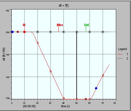
30 Figure 4: prompt pilot/prompt pilot Figure 5: prompt pilot/slow pilot Figure 6: prompt pilot/non-response pilot Version 3.0 Page 26
.")
. The scenario including the nominal values is also shown as a reference scenario, and underlined with a grey colour in the tables.")
31 Figure 7: prompt pilot/wrong pilot 4.2. Full system risk ratios The goal of this part is to present the full system risk ratio figures, which were computed for the various encounters describing CVSM and RVSM environments (i.e., for the full airspace). In some cases, a sensitivity analysis is performed. An ideal scenario is always shown. This ideal scenario includes all the parameters of interest set to their best possible value (e.g., all pilots following their RAs, etc). The scenario including the nominal values is also shown as a reference scenario, and underlined with a grey colour in the tables. This scenario includes the following proportions: 82.14% of pilots follow their RAs; 45.46% of them do it promptly; With phase I, 62.90% of the aircraft are equipped with ACAS II; and With phase II, 70.15% of the aircraft are equipped with ACAS II Nominal values The following table shows the full system risk ratios, which were computed using the event tree, for both the CVSM and the RVSM environments. Phase I CVSM Phase II CVSM Phase I RVSM Phase II RVSM Full system risk ratio 27.5% 21.7% 27.3% 21.5% Table 8: Full system risk ratios nominal values Version 3.0 Page 27
32 The full system risk ratios computed for the CVSM and RVSM environments are very close, which is in line with the observations made on logic risk ratios. It results from the fact that these full system risk ratios were computed for the full airspace, in which layer 5 has a small influence. The full system risk ratio computed for the current RVSM environment with phase II is 22% lower than the one computed with the former CVSM environment and phase I. Thus phase II brings significant improvements in terms of collision risk reduction. The full system risk ratios shown in table 8 will be referred as reference risk ratios in the following tables. It can be surprising that the full system risk ratios shown in table 8 are lower than the logic risk ratios shown in part 3. This is explained by the fact that when computing logic risk ratios, the possibility of visual acquisition is not taken into account. The full system risk ratios computed assuming the possibility of visual acquisition is removed are as follows: Phase I CVSM Phase II CVSM Phase I RVSM Phase II RVSM Full system risk ratio 55.8% 50.5% 55.2% 50.0% Table 9: Full system risk ratios nominal values possibility of visual acquisition not taken into account The fact that ACAS II helps in the visual acquisition nearly halves the full system risk ratios. This trend had already been observed in [12]. This function of ACAS has a significant implication in terms of safety, and this study shows that only full system risk ratios enable to take them into account. Version 3.0 Page 28
33 Sensitivity to the RA compliance rate The following table shows the full systems risk ratios computed with several RA compliance rates, for the CVSM and RVSM environments and for both phases. RA compliance rate Phase I CVSM Phase II CVSM Phase I RVSM Phase II RVSM 60.0% 30.1% 24.5% 30.0% 24.3% 82.14% (ref.) 27.5% 21.7% 27.3% 21.5% 100.0% 25.5% 19.5% 25.2% 19.3% Table 10: Full system risk ratios - sensitivity to the RA compliance rate Increasing the proportion of pilots who follow RAs from 60.0% to 82.14% decreases the risk ratios by between 2.6ppt and 2.8ppt. It emphasizes once again the need for pilots to follow their RAs. According to the event tree: 45.46% of the pilots who follow their RAs do it promptly; 54.44% of the pilots who follow their RAs do it slowly. The following table shows the full system risk ratios with several combinations of RA compliance rates, and with less or more pilots following RAs promptly. RA compliance rate Prompt pilots Phase I CVSM Phase II CVSM Phase I RVSM Phase II RVSM 82.14% 30.0% 28.8% 23.1% 28.6% 22.9% 82.14% (ref.) 45.46% (ref.) 27.5% 21.7% 27.3% 21.5% 90.0% 60.0% 25.3% 19.4% 25.1% 19.2% 100.0% 100.0% 20.7% 14.7% 20.5% 14.6% Table 11: Full system risk ratios - sensitivity to the RA compliance rate and to the proportion of prompt pilots Version 3.0 Page 29
34 These results clearly show that it is very important that pilots follow their RAs, but it is also very important they do it with the appropriate vertical rates and delays, as increasing the proportion of prompt pilots from 30.0% to 45.46% decreases the full system risk ratios by between 1.3ppt and 1.4ppt. Increasing the proportion of prompt pilots from 45.46% to 60.0% and increasing the proportion of pilots who follow their RAs from 82.14% to 90.0% decreases the risk ratios further by between 2.2ppt and 2.3ppt Sensitivity to the level of equipage The event tree assumes that 62.9% of aircraft will be fitted with ACAS with phase I, and that 70.15% of aircraft will be fitted with ACAS with phase II. The following table shows how the full system risk ratios would evolve assuming more aircraft are equipped in the future. Proportion of aircraft equipped CVSM RVSM 70.15% (ref.) 21.7% 21.5% 75.0% 18.5% 18.3% 100.0% 6.4% 6.4% Table 12: Full system risk ratios - sensitivity to the proportion of ACAS II equipped aircraft The results confirm that the computations of the safety brought by ACAS are very sensitive to the level of equipage. A small proportion of additional equipped aircraft increases significantly the benefits brought by ACAS on safety and highlights the benefits to the airspace of having a higher level of equipage: increasing the equipage from 70.15% to 75.0% decreases the full system risk ratio by 3.2ppt. Version 3.0 Page 30
35 Mixed scenarios The following table shows full system risk ratios for several scenarios which assume a higher proportion of equipped aircraft, a higher rate of RA compliance and a higher proportion of prompt pilots. RA compliance rate Prompt pilots Equipage CVSM RVSM 82.14% (ref.) 45.46% (ref.) 70.15% (ref.) 21.7% 21.5% 90.0% 60.0% 75.0% 16.2% 16.0% 95.0% 80.0% 80.0% 10.9% 10.7% 100.0% 100.0% 100.0% 1.3% 1.3% Table 13: Full system risk ratios mixed scenarios This table mainly shows that important gains in terms of risk of collision reduction are possible through an increased proportion of equipped aircraft together with an increased RA compliance rate and an increase in the number of prompt pilots. These parameters contribute highly in improving the benefits brought by ACAS II and are among the most influencing factors on the safety brought by ACAS (with visual acquisition). Version 3.0 Page 31
36 5. Conclusion 5.1. Overall This report clearly indicates that ACAS II brings significant benefits to safety in the European Airspace (cf , and 4.2.1) CVSM versus RVSM It was observed that the switch from the former CVSM environment to the RVSM environment does not decrease the safety benefits brought by ACAS II when considering the full airspace (cf , and 4.2.1). When considering the upper layer of the RVSM environment only, it is expected that ACAS II still brings benefits in terms of risk of collision reduction, but this safety benefit is lower in RVSM than in CVSM. However, ACAS II still decreases the risk of collision in this layer, especially if pilots follow their RAs (cf ) Phase II This study highlights the significant benefits brought by phase II of the mandate. These benefits will be mainly observed in the altitude layers going from 1000ft to FL290. The full system study showed that the risk of collision will be decreased by 22% with phase II (i.e., risk ratio decreased by 6ppt) (cf ). The study also indicates that equipage requirements beyond those of phase II of the European ACAS mandate would further improve the safety gains provided by ACAS II Pilot response The study also highlights the importance of pilot reaction, as even a proportion of 20% of the pilots not following their RAs debases the safety benefits brought by ACAS II, especially in the upper layer of the RVSM environment. Moreover, pilots must follow their RAs with the required vertical rates and with the expected reaction time. Therefore pilot training will continue to be a very important matter when proceeding with phase II (cf , 4.2.2, 4.2.3). 6. Recommendations It is proposed that: the interest of fitting ACAS to smaller aircraft is brought to the attention of European decision makers to support phase II of the ACAS implementation; the need to follow correctly the RAs must be emphasized as this study shows that not following RAs debases the safety benefits brought by ACAS. Version 3.0 Page 32
37 7. Acronyms ACAS ACASA ATC CENA ECAC FL FLnnn fpm hmd ICAO MASPS NM NMAC RA RVSM SARPs Airborne Collision Avoidance System ACAS Analysis Air Traffic Control Centre d Études de la Navigation Aerienne European Civil Aviation Conference Flight Level The Flight Level at nnn00ft feet per minute: a unit of vertical speed horizontal miss distance International Civil Aviation Organization Minimum Aviation System Performance Standards International Nautical Mile Near Mid-Air Collision Resolution Advisory Reduced Vertical Separation Minimum Standards and Recommended Practices an ICAO document Sofréavia Societé Francaise d Études et Realisations d Equipements Aeronautiques TA TCAS vmd Traffic Advisory Traffic alert and Collision Avoidance System, an ACAS vertical miss distance Version 3.0 Page 33
38 8. Definitions ACAS II encounter Flight Level An ACAS that generates vertical, but not horizontal, avoidance manoeuvre advice. Usually a pair of aircraft trajectories that are, in some sense that is defined by the context, close. Barometric altitude, measured in units of 100ft, referenced to a standard pressure of hPa. horizontal miss distance large aircraft light aircraft logic risk ratio Mode C The horizontal separation at the time of closest approach between the two aircraft in an encounter. In this report, a large aircraft is an aircraft covered by Phase 1 of the European ACAS II mandate, i.e. one having a maximum take-off mass exceeding 15,000kg or a maximum approved seating configuration of more than 30. In this report, all aircraft except large aircraft, small aircraft and military fighters. The proportional reduction in the risk of collision calculated for stated assumptions concerning the performance of ACAS. Typical assumptions are that certain aircraft are equipped, that all aircraft report altitude and a certain proportion do so in 25ft increments (as opposed to 100ft increments), that ACAS surveillance is perfect and that pilots response exactly as intended. Logic risk ratio is a measure of the performance of the collision avoidance logic. A mode of secondary surveillance radar replies that reports altitude in whole units of 100ft. Version 3.0 Page 34
39 Mode S percentage points Resolution Advisory A mode of secondary surveillance radar that enables interrogators to address individual aircraft using their unique aircraft addresses. The replies contain aircraft address, altitude and other information. Aircraft fitted with ACAS II must be fitted with a Mode S transponder. Mode S transponders can report altitude either in whole units of 25ft or in whole units of 100ft. The numerical difference between two percentages. In this report, the abbreviation ppt is sometimes preferred to % when discussing a statistic that is already expressed as a percentage. The purpose is to make it clear that the quantity is an absolute change in the value of the statistic, rather than a proportional change. Thus, if the statistic has a value of X%, a reduction of Yppt results in a value of (X Y )% An alert issued by ACAS II advising the pilot to take avoiding action in the vertical plane. RAs may be corrective (requiring the pilot to manoeuvre vertically) or preventive (requiring no immediate manoeuvre but proscribing a range of vertical speeds). Reduced Vertical Separation Minimum risk ratio small aircraft system risk ratio Traffic Advisory The regime in which the standard cruising levels are separated by 1000ft between FL290 to FL410 inclusive. The ratio of the risk of collision with ACAS to the risk of collision without ACAS. In this report, a small aircraft is an aircraft that is not large, but is covered by Phase 2 of the European ACAS II mandate, i.e. having a maximum take-off mass exceeding 5700kg or a maximum approved seating configuration of more than 19. A calculation of risk ratio for the ACAS system as a whole, with estimates made for the probable performance of all parts of ACAS, pilots and equipment on other aircraft. A preliminary alert issued by ACAS II in order to cue a visual search for the potential threat, and to prepare the pilot for a possible Resolution Advisory. Version 3.0 Page 35
40 version 7 vertical miss distance The current release of the TCAS collision avoidance logic. A requirement to fit ACAS II (conforming to the ICAO SARPs) implies a requirement to fit version 7 as opposed to version 6.04A. The vertical separation at the time of closest approach between the two aircraft in an encounter. Version 3.0 Page 36
41 9. Appendix A : altimeter error model The risk ratio is computed applying an altimeter error model to the trajectories of the aircraft. This altimeter error model is defined in the ACAS SARPS [6]. This error is distributed as a Laplacian distribution with zero mean having probability density: p( e) = 1 e exp( ) 2λ λ where p(e) is the probability density function of altimetry error of value e. The probability that the altimetry error is greater than a value x is as follows: x p( e > x) = exp( ) λ 7KHÃSDUDPHWHUÃ ÃUHTXLUHGÃIRUÃWKHÃGHILQLWLRQÃRIÃVWDWLVWLFDOÃGLVWULEXWLRQÃRIÃDOWLPHWHUÃHUURU IRUÃHDFKÃDLUFUDIWÃFDQÃWDNHÃWZRÃYDOXHVÃ 1 ÃDQGÃ 2, which depend on the altitude layer. For an aircraft equipped with ACAS, the value of ÃLVÃ 1. For aircraft not equipped with ACAS, the value of ÃLVÃVHOHFWHGÃUDQGRPO\ÃEHWZHHQÃ 1ÃDQGÃ 2. The values of 1 ÃDQGÃ 2 for the altitudes corresponding to the upper layer of the RVSM environment are 72ft and 101ft according to SARPS. These values do not comply with MASPS in case of RVSM. For this reason, the altimeter error model was modified specifically for RVSM simulations so that the aircraft flying in the altitude band between FL290 and FL410 DUHÃ0$636Ã FRPSOLDQWÃ 7KXVÃ Ã ZDVÃ VHWÃ WRÃIWÃ IRUÃ WKHÃ DOWLWXGHÃEDQGÃEHWZHHQÃ )/ and FL410, when simulating RVSM. This value was chosen on the basis of [7] which GHPRQVWUDWHVÃWKDWÃFKRRVLQJÃ IWÃLVÃFRQVLVWHQWÃZLWKÃWKHÃUHTXLUHPHQWÃRIÃWKHÃ0$636 This assumes that all the aircraft flying in the RVSM altitude band are MASPS compliant. Version 3.0 Page 37


42 10. Appendix B: problem encounters The analysis of the sets NMAC (cf ) showed that a specific geometry is majority. The following figure presents such an encounter. Figure 8: Induced NMAC layer 5 Phase I The pilot of the descending aircraft does not follow his Ras The left view shows the encounter without ACAS contribution. The right view shows the encounter with ACAS contribution. On both views, the upper figure shows the encounter in the horizontal plane, whereas the lower view shows the altitude of the aircraft versus time. In this encounter, an ACAS II equipped aircraft (i.e., a small jet aircraft) is descending towards another ACAS II equipped aircraft. The vertical separation at CPA without ACAS contribution is 950ft. Version 3.0 Page 38

43 We observe that the level aircraft is given a Descend RA. Then, an increase descent RA is triggered. The pilot of the descending aircraft does not follow his Climb RA. This encounter results in an almost nil vertical separation at CPA. The simulations with both aircraft pilots following their RAs result in a vertical separation at CPA of 1000ft. The following figure shows the result of the simulation for this encounter, with both aircraft equipped with ACAS II. Figure 9: Same encounter layer 5 Phase II both pilots follow their RAs The level aircraft still has a Descend RA, but this time the descending aircraft follows the Climb RA, which ensures a vertical separation at CPA of 1000ft. This encounter highlights once again the need for pilots to follow their RAs. In addition, similar encounters also occur with the descending aircraft not equipped with ACAS II, and also result in NMACs. These encounters represent a significant proportion of the NMACs. Version 3.0 Page 39
EUROCONTROL AVAL Project. AVAL Phase 1 findings (presented by Thierry Arino)
") EUROCONTROL AVAL Project AVAL Phase 1 findings (presented by Thierry Arino) Slide 1 Presentation content Introduction Safety benefits of ACAS VLJs and LJs below 5,700 kg: what are they? What are the safety
EUROCONTROL AVAL Project AVAL Phase 1 findings (presented by Thierry Arino) Slide 1 Presentation content Introduction Safety benefits of ACAS VLJs and LJs below 5,700 kg: what are they? What are the safety
ACAS on VLJs and LJs Assessment of safety Level (AVAL) Outcomes of the AVAL study (presented by Thierry Arino, Egis Avia)
 Outcomes of the AVAL study (presented by Thierry Arino, Egis Avia)") ACAS on VLJs and LJs Assessment of safety Level (AVAL) Outcomes of the AVAL study (presented by Thierry Arino, Egis Avia) Slide 1 Presentation content Introduction Background on Airborne Collision Avoidance
ACAS on VLJs and LJs Assessment of safety Level (AVAL) Outcomes of the AVAL study (presented by Thierry Arino, Egis Avia) Slide 1 Presentation content Introduction Background on Airborne Collision Avoidance
ACAS PROGRAMME. EMOTION-7 Final Report European Maintenance of TCAS II version 7.0 Project EMOTION-7
 ACAS PROGRAMME EMOTION-7 Final Report European Maintenance of TCAS II version 7.0 Project EMOTION-7 ACAS/03-003 Edition : 1 Edition Date : January 2003 Status : Released Issue Class : EATMP EUROCONTROL
TCAS Pilot training issues
 November 2011 TCAS Pilot training issues This Briefing Leaflet is based in the main on the ACAS bulletin issued by Eurocontrol in February of 2011. This Bulletin focuses on pilot training, featuring a
TRAFFIC ALERT AND COLLISION AVOIDANCE SYSTEM (TCAS II)
") TRAFFIC ALERT AND COLLISION AVOIDANCE SYSTEM (TCAS II) Version 1.0 Effective June 2004 CASADOC 205 Traffic Alert and Collision Avoidance System (TCAS II) This is an internal CASA document. It contains
TRAFFIC ALERT AND COLLISION AVOIDANCE SYSTEM (TCAS II) Version 1.0 Effective June 2004 CASADOC 205 Traffic Alert and Collision Avoidance System (TCAS II) This is an internal CASA document. It contains
CAR Section II Series I Part VIII is proposed to be amended. The proposed amendments are shown in subsequent affect paragraphs.
 CAR Section II Series I Part VIII is proposed to be amended. The proposed amendments are shown in subsequent affect paragraphs. The text of the amendment is arranged to show deleted text, new or amended
Analysis of en-route vertical flight efficiency
 Analysis of en-route vertical flight efficiency Technical report on the analysis of en-route vertical flight efficiency Edition Number: 00-04 Edition Date: 19/01/2017 Status: Submitted for consultation
Collision risk due to TCAS safety issues
 EUROPEAN ORGANISATION FOR THE SAFETY OF AIR NAVIGATION EUROCONTROL Collision risk due to TCAS safety issues Investigation and analysis of TCAS II safety issues in the European airspace Edition Number :
EUROPEAN ORGANISATION FOR THE SAFETY OF AIR NAVIGATION
 EUROPEAN ORGANISATION FOR THE SAFETY OF AIR NAVIGATION EUROCONTROL TCAS II performance in European TMAs Part 1: Analysis Safety Issue Rectification Extension 2006-2008 Project SIRE+ Project CND/CoE/CNS/09-047
Pilot RVSM Training Guidance Material
 Pilot RVSM Training Guidance Material Captain Souhaiel DALLEL IFALPA RVP AFI WEST RVSM Pilot Procedures ICAO requires states to establish for flight crews specific: Initial training programs and Recurrent
SAFETY BULLETIN. One Level of Safety Worldwide Safety Bulletin No. 05SAB004 5 July 2004
 IFLP SFETY BULLETIN THE GLOBL VOICE OF PILOTS One Level of Safety Worldwide Safety Bulletin No. 05SB004 5 July 2004 CS II - TCS II and VFR traffic This Document was produced in co-operation with EUROCTROL
Safety Analysis of Upgrading to TCAS Version 7.1 Using the 2008 U.S. Correlated Encounter Model
 Project Report ATC-349 Safety Analysis of Upgrading to TCAS Version 7.1 Using the 2008 U.S. Correlated Encounter Model L.P. Espindle J.D. Griffith J.K. Kuchar 11 May 2009 Lincoln Laboratory MASSACHUSETTS
Appendix B Ultimate Airport Capacity and Delay Simulation Modeling Analysis
 Appendix B ULTIMATE AIRPORT CAPACITY & DELAY SIMULATION MODELING ANALYSIS B TABLE OF CONTENTS EXHIBITS TABLES B.1 Introduction... 1 B.2 Simulation Modeling Assumption and Methodology... 4 B.2.1 Runway
Overview of ACAS II / TCAS II
 Maastricht ATC 2006 Overview of ACAS II / TCAS II DISCLAIMER 2009 The European Organisation for the Safety of Air Navigation (EUROCONTROL). This document is published by EUROCONTROL for information purposes.
SECTION 6 - SEPARATION STANDARDS
 SECTION 6 - SEPARATION STANDARDS CHAPTER 1 - PROVISION OF STANDARD SEPARATION 1.1 Standard vertical or horizontal separation shall be provided between: a) All flights in Class A airspace. b) IFR flights
Establishing a Risk-Based Separation Standard for Unmanned Aircraft Self Separation
 Establishing a Risk-Based Separation Standard for Unmanned Aircraft Self Separation Roland E. Weibel, Matthew W.M. Edwards, and Caroline S. Fernandes MIT Lincoln laboratory Surveillance Systems Group Ninth
USE OF RADAR IN THE APPROACH CONTROL SERVICE
 USE OF RADAR IN THE APPROACH CONTROL SERVICE 1. Introduction The indications presented on the ATS surveillance system named radar may be used to perform the aerodrome, approach and en-route control service:
Safety benefits of ACAS in the future European ATM environment with Very Light Jets -
 EUROPEAN ORGANISATION FOR THE SAFETY OF AIR NAVIGATION EUROCONTROL Safety benefits of ACAS in the future European ATM environment with Very Light Jets - AVAL final report CND/CoE/CNS/09-142 Edition Number
ACAS Training for Pilots
 United Kingdom Overseas Territories Aviation Circular OTAC 91-5 119-8 121-6 125-6 135-6 ACAS Training for Pilots Issue 1 15 September 2011 Effective date: on issue GENERAL Overseas Territories Aviation
AIRBUS 12 th Performance and
 FOLLOW THE RA! MANAGING TCAS RA ORDERS AND ATC INSTRUCTIONS By Michel TREMAUD Sr.Dir. Operational Standards Development and Flight Operations Safety 1. INTRODUCTION 1.1. Background The midair collision
CLEARANCE INSTRUCTION READ BACK
 CLEARANCE INSTRUCTION READ BACK 1. Introduction An ATC clearance or an instruction constitutes authority for an aircraft to proceed only in so far as known air traffic is concerned and is based solely
TWELFTH AIR NAVIGATION CONFERENCE
 International Civil Aviation Organization 17/5/12 WORKING PAPER TWELFTH AIR NAVIGATION CONFERENCE Montréal, 19 to 30 November 2012 Agenda Item 4: Optimum Capacity and Efficiency through global collaborative
Interim Statement Ref. AAIU
 SYNOPSYS Interim Statement Ref. Air Accident Investigation Unit (Belgium) City Atrium Rue du Progrès 56 1210 Brussels SYNOPSIS Date and time: Aircraft: Sunday 01 January 2017 at 11:47 UTC a. Airbus A320-214.
Mode S & ACAS Programme Operational Introduction of SSR Mode S
 Mode S & ACAS Programme Operational Introduction of SSR Mode S John Law Programme Manager john.law@eurocontrol.int Tel: +32 2 729 3766 European 1 Organisation for the Safety of Air Navigation Mode S Airborne
CASCADE OPERATIONAL FOCUS GROUP (OFG)
") CASCADE OPERATIONAL FOCUS GROUP (OFG) Use of ADS-B for Enhanced Traffic Situational Awareness by Flight Crew During Flight Operations Airborne Surveillance (ATSA-AIRB) 1. INTRODUCTION TO ATSA-AIRB In today
CASCADE OPERATIONAL FOCUS GROUP (OFG) Use of ADS-B for Enhanced Traffic Situational Awareness by Flight Crew During Flight Operations Airborne Surveillance (ATSA-AIRB) 1. INTRODUCTION TO ATSA-AIRB In today
New issues raised on collision avoidance by the introduction of remotely piloted aircraft (RPA) in the ATM system
 in the ATM system") New issues raised on collision avoidance by the introduction of remotely piloted aircraft (RPA) in the ATM system Jean-Marc Loscos DSNA expert on collision avoidance and airborne surveillance EIWAC 2013
New issues raised on collision avoidance by the introduction of remotely piloted aircraft (RPA) in the ATM system Jean-Marc Loscos DSNA expert on collision avoidance and airborne surveillance EIWAC 2013
AIR NAVIGATION COMMISSION
 13/2/04 AIR NAVIGATION COMMISSION ANC Task No. CNS-7901: Conflict resolution and collision avoidance systems PRELIMINARY REVIEW OF PROPOSED AMENDMENTS TO ANNEX 6, PART II TO INCLUDE PROVISIONS CONCERNING
(DRAFT) AFI REDUCED VERTICAL SEPARATION MINIMUM (RVSM) RVSM SAFETY POLICY
 AFI REDUCED VERTICAL SEPARATION MINIMUM (RVSM) RVSM SAFETY POLICY") (DRAFT) AFI REDUCED VERTICAL SEPARATION MINIMUM (RVSM) RVSM SAFETY POLICY 26 May 04 TABLE OF CONTENTS CONTENTS... PAGE SECTION 1: INTRODUCTION...3 SECTION 2: RVSM OPERATIONAL CONCEPT...3 SECTION 3: AFI
(DRAFT) AFI REDUCED VERTICAL SEPARATION MINIMUM (RVSM) RVSM SAFETY POLICY 26 May 04 TABLE OF CONTENTS CONTENTS... PAGE SECTION 1: INTRODUCTION...3 SECTION 2: RVSM OPERATIONAL CONCEPT...3 SECTION 3: AFI
Overview. ETSO Workshop 2008 New Developments in Avionic. Friedhelm Runge
 ETSO Workshop 2008 New Developments in Avionic Friedhelm Runge Parts & Appliances Avionics PCM Dec. 2008 P&A section 1 Overview Single European Sky Communication Datalink 8.33 khz VHF Navigation ICAO PBN
OPERATIONS MANUAL PART A
 PAGE: 1 Table of Contents A.GENERAL /CHAPTER 32. -...3 32. OF THE AIRBORNE COLLISION AVOIDANCE... 3 32.1 ACAS Training Requirements... 3 32.2 Policy and Procedures for the use of ACAS or TCAS (as applicable)...
EASA NPA on SERA Part ENAV Response sheet. GENERAL COMMENTS ON NPA PACKAGE Note: Specific comments are provided after the General Comments
 EASA NPA on SERA Part ENAV Response sheet GENERAL COMMENTS ON NPA PACKAGE te: Specific comments are provided after the General Comments 1 SERA Parts C and D ENAV still misses clarity on the whole scope
IMPROVING THE RESOLUTION ADVISORY REVERSAL LOGIC OF THE TRAFFIC ALERT AND COLLISION AVOIDANCE SYSTEM
 2006 IEEE. Personal use of this material is permitted. However, permission to reprint/republish this material for advertising or promotional purposes or for creating new collective works for resale or
Official Journal of the European Union L 186/27
 7.7.2006 Official Journal of the European Union L 186/27 COMMISSION REGULATION (EC) No 1032/2006 of 6 July 2006 laying down requirements for automatic systems for the exchange of flight data for the purpose
Runway Length Analysis Prescott Municipal Airport
 APPENDIX 2 Runway Length Analysis Prescott Municipal Airport May 11, 2009 Version 2 (draft) Table of Contents Introduction... 1-1 Section 1 Purpose & Need... 1-2 Section 2 Design Standards...1-3 Section
helicopter? Fixed wing 4p58 HINDSIGHT SITUATIONAL EXAMPLE
 HINDSIGHT SITUATIONAL EXAMPLE Fixed wing or helicopter? Editorial note: Situational examples are based on the experience of the authors and do not represent either a particular historical event or a full
Overview ICAO Standards and Recommended Practices for Aerodrome Safeguarding
 Overview ICAO Standards and Recommended Practices for Aerodrome Safeguarding References The Convention on International Civil Aviation (Chicago Convention) ICAO SARPS Annex 14 Vol. I, 7 th Edition, July
Rates of reportable accidents were highest
 U.K. Business Jet Accident Rates Comparatively High Engine problems were the most frequent factor in serious incidents among large aircraft. BY RICK DARBY Rates of reportable accidents were highest for
CHAPTER 5 SEPARATION METHODS AND MINIMA
 CHAPTER 5 SEPARATION METHODS AND MINIMA 5.1 Provision for the separation of controlled traffic 5.1.1 Vertical or horizontal separation shall be provided: a) between IFR flights in Class D and E airspaces
GENERAL REPORT. Reduced Lateral Separation Minima RLatSM Phase 2. RLatSM Phase 3
 IBAC TECHNICAL REPORT SUMMARY Subject: NAT Operations and Air Traffic Management Meeting: North Atlantic (NAT) Procedures and Operations Group Meeting 2 Reported by Tom Young POG2 took place at the ICAO
Airspace Encounter Models for Conventional and Unconventional Aircraft
 Airspace Encounter Models for Conventional and Unconventional Aircraft Matthew W. Edwards, Mykel J. Kochenderfer, Leo P. Espindle, James K. Kuchar, and J. Daniel Griffith Eighth USA/Europe Air Traffic
Date: 29 Apr 2017 Time: 1119Z Position: 5226N 00112W Location: 10nm ENE Coventry
 AIRPROX REPORT No 2017080 Date: 29 Apr 2017 Time: 1119Z Position: 5226N 00112W Location: 10nm ENE Coventry PART A: SUMMARY OF INFORMATION REPORTED TO UKAB Recorded Aircraft 1 Aircraft 2 Aircraft C560 PA28
TCAS RA not followed. Tzvetomir BLAJEV Stan DROZDOWSKI
 TCAS RA not followed Tzvetomir BLAJEV Stan DROZDOWSKI EUROCONTROL European Organisation for the Safety of Air Navigation Civil-military intergovernmental organisation 41 Member States 2 Comprehensive Agreement
Republic of Iraq Ministry of Transport Iraq Civil Aviation Authority REGULATIONS (31) RVSM OPERATIONS IN REDUCED VERTICAL SEPARATION MINIMUM AIRSPACE
 RVSM OPERATIONS IN REDUCED VERTICAL SEPARATION MINIMUM AIRSPACE") Republic of Iraq Ministry of Transport Iraq Civil Aviation Authority REGULATIONS (31) RVSM OPERATIONS IN REDUCED VERTICAL SEPARATION MINIMUM AIRSPACE Amendments Location Date Description Regulations No.31
Republic of Iraq Ministry of Transport Iraq Civil Aviation Authority REGULATIONS (31) RVSM OPERATIONS IN REDUCED VERTICAL SEPARATION MINIMUM AIRSPACE Amendments Location Date Description Regulations No.31
IFR SEPARATION USING RADAR
 IFR SEPARATION USING RADAR 1. Introduction When flying IFR inside controlled airspace, air traffic controllers either providing a service to an aircraft under their control or to another controller s traffic,
TWELFTH AIR NAVIGATION CONFERENCE
 International Civil Aviation Organization AN-Conf/12-WP/8 7/5/12 WORKING PAPER TWELFTH AIR NAVIGATION CONFERENCE Montréal, 19 to 30 November 2012 Agenda Item 3: Interoperability and data through globally
For a 1309 System Approach of the Conflict Management
 For a 1309 System Approach of the Conflict Management Airborne Conflict Safety Forum Eurocontrol 10/11 June 2014 Serge.LEBOURG@Dassault-Aviation.com SL2014-08 System Approach Conflict Management Eurocontrol
Date: 29 Jun 2018 Time: 1502Z Position: 5325N 00312W Location: 5nm NW Liverpool Airport
 AIRPROX REPORT No 2018158 Date: 29 Jun 2018 Time: 1502Z Position: 5325N 00312W Location: 5nm NW Liverpool Airport PART A: SUMMARY OF INFORMATION REPORTED TO UKAB Recorded Aircraft 1 Aircraft 2 Aircraft
1/2 July Draft Commission Implementing Regulation amending Regulation (EU) No 1207/2011 (Surveillance Performance and Interoperability SPI)
 No 1207/2011 (Surveillance Performance and Interoperability SPI)") SSC/14/54/5 Agenda Item 4.1 16 June 2014 54 th SINGLE SKY COMMITTEE 1/2 July 2014 Draft Commission Implementing Regulation amending Regulation (EU) No 1207/2011 (Surveillance Performance and Interoperability
SSC/14/54/5 Agenda Item 4.1 16 June 2014 54 th SINGLE SKY COMMITTEE 1/2 July 2014 Draft Commission Implementing Regulation amending Regulation (EU) No 1207/2011 (Surveillance Performance and Interoperability
FLIGHT OPERATIONS PANEL
 International Civil Aviation Organization FLTOPSP/WG/2-WP/14 27/04/2015 WORKING PAPER FLIGHT OPERATIONS PANEL WORKING GROUP SECOND MEETING (FLTOPSP/WG/2) Rome Italy, 4 to 8 May 2015 Agenda Item 4 : Active
EUROPEAN COMMISSION DIRECTORATE-GENERAL FOR MOBILITY AND TRANSPORT
 EUROPEAN COMMISSION DIRECTORATE-GENERAL FOR MOBILITY AND TRANSPORT DIRECTORATE E - Air Transport E.2 - Single sky & modernisation of air traffic control Brussels, 6 April 2011 MOVE E2/EMM D(2011) 1. TITLE
Performance Indicator Horizontal Flight Efficiency
 Performance Indicator Horizontal Flight Efficiency Level 1 and 2 documentation of the Horizontal Flight Efficiency key performance indicators Overview This document is a template for a Level 1 & Level
Ref.: AN 11/19-02/82 30 August 2002
 Tel.: + 1 (514) 954-8219 ext. 8077 Ref.: AN 11/19-02/82 30 August 2002 Subject: ACAS PROVISIONS AND OPERATIONAL PROCEDURES Action required: TO ENSURE THAT NATIONAL AVIATION DOCUMENTATION AND THAT OF AIRCRAFT
Efficiency and Automation
 Efficiency and Automation Towards higher levels of automation in Air Traffic Management HALA! Summer School Cursos de Verano Politécnica de Madrid La Granja, July 2011 Guest Lecturer: Rosa Arnaldo Universidad
NATA Aircraft Maintenance & System Technology Committee Best Practices. RVSM Maintenance
 NATA Aircraft Maintenance & System Technology Committee Best Practices Reduced Vertical Separation Minimum (RVSM) Airspace reduces the vertical separation above flight level (FL) 290 from 2000-ft minimum
OPERATIONS CIRCULAR 7 of 2010
 GOVERNMENT OF INDIA CIVIL AVIATION DEPARTMENT OFFICE OF THE DIRECTOR GENERAL OF CIVIL AVIATION OPP. SAFDARJUNG AIRPORT, NEW DELHI 110 003 TELEPHONE: 091-011-24635261 24644768 FAX: 091-011-24644764 TELEX:
FINAL REPORT BOEING B777, REGISTRATION 9V-SWH LOSS OF SEPARATION EVENT 3 JULY 2014
 FINAL REPORT BOEING B777, REGISTRATION 9V-SWH LOSS OF SEPARATION EVENT 3 JULY 2014 AIB/AAI/CAS.109 Air Accident Investigation Bureau of Singapore Ministry of Transport Singapore 11 November 2015 The Air
EUR/SAM corridor airspace concept
 TWENTYENTH MEETING ON THE IMPROVEMENT OF AIR TRAFFIC SERVICES OVER THE SOUTH ATLANTIC (SAT21) (Lisbon, Portugal, 8 to 10 June, 2016) Agenda Item 2: Air traffic management (ATM) RNP 4 IN THE EUR/SAM CORRIDOR
Date: 14 Jun 2017 Time: 1600Z Position: 5121N 00102W Location: 7nm NW Blackbushe airport
 AIRPROX REPORT No 2017113 Date: 14 Jun 2017 Time: 1600Z Position: 5121N 00102W Location: 7nm NW Blackbushe airport PART A: SUMMARY OF INFORMATION REPORTED TO UKAB Recorded Aircraft 1 Aircraft 2 Aircraft
Approach-and-Landing Briefing Note Response to GPWS Pull-Up Maneuver Training
 Approach-and-Landing Briefing Note 6.3 - Response to GPWS Pull-Up Maneuver Training Introduction A typical awareness and training program for the reduction of approach-and-landing accidents involving controlled-flight-into-terrain
Any queries about the content of the attached document should be addressed to: ICAO EUR/NAT Office:
 Serial Number: 2018_005 Subject: Special Procedures For In-Flight Contingencies in Oceanic Airspace Originator: NAT SPG Issued: 17 DEC 2018 Effective:28 MAR 2019 The purpose of this North Atlantic Operations
Design Airspace (Routes, Approaches and Holds) Module 11 Activity 7. European Airspace Concept Workshops for PBN Implementation
 Module 11 Activity 7. European Airspace Concept Workshops for PBN Implementation") Design Airspace (Routes, Approaches and Holds) Module 11 Activity 7 European Airspace Concept Workshops for PBN Implementation Design in Context TFC Where does the traffic come from? And when? RWY Which
Design Airspace (Routes, Approaches and Holds) Module 11 Activity 7 European Airspace Concept Workshops for PBN Implementation Design in Context TFC Where does the traffic come from? And when? RWY Which
Efficiency and Environment KPAs
 Efficiency and Environment KPAs Regional Performance Framework Workshop, Bishkek, Kyrgyzstan, 21 23 May 2013 ICAO European and North Atlantic Office 20 May 2013 Page 1 Efficiency (Doc 9854) Doc 9854 Appendix
Advisory Circular. Airborne Collision Avoidance System Advisory Material
 Advisory Circular Subject: Airborne Collision Avoidance System Advisory Material Issuing Office: Standards Document No.: AC 700-004 File Classification No.: Z 5000-34 Issue No.: 02 RDIMS No.: 7997323-V12
LARGE HEIGHT DEVIATION ANALYSIS FOR THE WESTERN ATLANTIC ROUTE SYSTEM (WATRS) AIRSPACE CALENDAR YEAR 2016
 AIRSPACE CALENDAR YEAR 2016") International Civil Aviation Organization Seventeenth meeting of the GREPECAS Scrutiny Working Group (GTE/17) Lima, Peru, 30 October to 03 November 2017 GTE/17-WP/07 23/10/17 Agenda Item 4: Large Height
International Civil Aviation Organization Seventeenth meeting of the GREPECAS Scrutiny Working Group (GTE/17) Lima, Peru, 30 October to 03 November 2017 GTE/17-WP/07 23/10/17 Agenda Item 4: Large Height
Date: 01 Jun 2018 Time: 0959Z Position: 5121N 00048W Location: 6nm N Farnborough
 AIRPROX REPORT No 2018103 Date: 01 Jun 2018 Time: 0959Z Position: 5121N 00048W Location: 6nm N Farnborough PART A: SUMMARY OF INFORMATION REPORTED TO UKAB Recorded Aircraft 1 Aircraft 2 Aircraft DA62 BE90
OPS 1 Standard Operating Procedures
 OPS 1 Standard Operating Procedures 1. Introduction 1.1. Adherence to standard operating procedures (SOPs) is an effective method of preventing level busts, including those that lead to controlled flight
Airspace Complexity Measurement: An Air Traffic Control Simulation Analysis
 Airspace Complexity Measurement: An Air Traffic Control Simulation Analysis Parimal Kopardekar NASA Ames Research Center Albert Schwartz, Sherri Magyarits, and Jessica Rhodes FAA William J. Hughes Technical
SUMMARY. of the North. Reference: A B
 International Civil Aviation Organization South American Regional Office 10/ /10/17 Twentieth Workshop/Meeting of the SAM Implementation Group (SAM/IG/20) - Regional Project RLA/06/901 (Lima, Peru, 16
THE AREA CONTROL CENTRE (CTR) POSITION
 POSITION") THE AREA CONTROL CENTRE (CTR) POSITION 1. Introduction The Area Control Centre (ACC) also known as en-route controller and called CTR on IVAO, has the responsibility of ensuring Air Traffic Control (ATC)
THE AREA CONTROL CENTRE (CTR) POSITION 1. Introduction The Area Control Centre (ACC) also known as en-route controller and called CTR on IVAO, has the responsibility of ensuring Air Traffic Control (ATC)
Interoperability of Horizontal and Vertical Resolution Advisories
 Eleventh USA/Europe Air Traffic Management Research and Development Seminar (ATM2015) Interoperability of Horizontal and Vertical Resolution Advisories Edward H. Londner Lincoln Laboratory Massachusetts
Contents. Subpart A General 91.1 Purpose... 7
 Contents Rule objective... 3 Extent of consultation... 3 Summary of comments... 4 Examination of comments... 6 Insertion of Amendments... 6 Effective date of rule... 6 Availability of rules... 6 Part 91
ACTION PLAN 1 FAA/EUROCONTROL COOPERATIVE R&D. Principles of Operation for the Use of Airborne Separation Assurance Systems
 ACTION PLAN 1 FAA/EUROCONTROL COOPERATIVE R&D Principles of Operation for the Use of Airborne Separation Assurance Systems Version: 7.1 Date: 19 June 2001 Executive summary This work was conducted under
1. Background. 2. Summary and conclusion. 3. Flight efficiency parameters. Stockholm 04 May, 2011
 Stockholm 04 May, 2011 1. Background By this document SAS want to argue against a common statement that goes: Green departures are much more fuel/emission efficient than green arrivals due to the fact
ACAS II Guide. Airborne Collision Avoidance System II (incorporating version 7.1)
") ACAS II Guide Airborne Collision Avoidance System II (incorporating version 7.1) January 2012 EUROCONTROL 2 ACAS II GUIDE January 2012 NOTE This Guide has been designed to support the training of people
ACAS II Guide Airborne Collision Avoidance System II (incorporating version 7.1) January 2012 EUROCONTROL 2 ACAS II GUIDE January 2012 NOTE This Guide has been designed to support the training of people
Terms of Reference for a rulemaking task. Implementation of Evidence-Based Training within the European regulatory framework RMT.0696 ISSUE
 Terms of Reference for a rulemaking task Implementation of Evidence-Based Training within the European regulatory framework ISSUE 1 3.9.2015 Applicability Process map Affected regulations and decisions:
Date: 01 Aug 2016 Time: 1344Z Position: 5441N 00241W
 AIRPROX REPORT No 2016157 Date: 01 Aug 2016 Time: 1344Z Position: 5441N 00241W Location: Langwathby PART A: SUMMARY OF INFORMATION REPORTED TO UKAB Recorded Aircraft 1 Aircraft 2 Aircraft AS365 King Air
NOISE ABATEMENT PROCEDURES
 1. Introduction NOISE ABATEMENT PROCEDURES Many airports today impose restrictions on aircraft movements. These include: Curfew time Maximum permitted noise levels Noise surcharges Engine run up restrictions
ATM 1 Understanding the Causes of Level Busts
 Level Bust Briefing Notes Air Traffic Management ATM 1 Understanding the Causes of Level Busts 1. Introduction 1.1. Most level busts result because the pilot flies the aircraft through the cleared level
IFR SEPARATION WITHOUT RADAR
 1. Introduction IFR SEPARATION WITHOUT RADAR When flying IFR inside controlled airspace, air traffic controllers either providing a service to an aircraft under their control or to another controller s
Review of brisbane Airport Noise Abatement Procedures
 Review of brisbane Airport Noise Abatement Procedures 1. Summary This document presents an overview of the findings of the review of the Noise Abatement Procedures in place for Brisbane Airport. The technical
Nav Specs and Procedure Design Module 12 Activities 8 and 10. European Airspace Concept Workshops for PBN Implementation
 Nav Specs and Procedure Design Module 12 Activities 8 and 10 European Airspace Concept Workshops for PBN Implementation Learning Objectives By the end of this presentation you should understand: The different
TENTH SESSION OF THE STATISTICS DIVISION
 International Civil Aviation Organization STA/10-WP/18 07/10/09 WORKING PAPER TENTH SESSION OF THE STATISTICS DIVISION Montréal, 23 to 27 November 2009 Agenda Item 8: Civil aircraft on register and data
EXPERIMENTAL ANALYSIS OF THE INTEGRATION OF MIXED SURVEILLANCE FREQUENCY INTO OCEANIC ATC OPERATIONS
 EXPERIMENTAL ANALYSIS OF THE INTEGRATION OF MIXED SURVEILLANCE FREQUENCY INTO OCEANIC ATC OPERATIONS Laura Major Forest & R. John Hansman C.S. Draper Laboratory, Cambridge, MA 9 USA; lforest@draper.com
Proposed Changes to Inverness Airport s Airspace The Introduction of Controlled Airspace and Optimisation of Instrument Flight Procedures
 Proposed Changes to Inverness Airport s Airspace The Introduction of Controlled Airspace and Optimisation of Instrument Flight Procedures What is an Airspace Change Proposal? It is a formal UK Civil Aviation
Advisory Circular. Regulations for Terrain Awareness Warning System
 Advisory Circular Subject: Regulations for Terrain Awareness Warning System Issuing Office: Standards Document No.: AC 600-003 File Classification No.: Z 5000-34 Issue No.: 03 RDIMS No.: 10464059-V5 Effective
Advisory Circular. Flight Deck Automation Policy and Manual Flying in Operations and Training
 Advisory Circular Subject: Flight Deck Automation Policy and Manual Flying in Operations and Training Issuing Office: Civil Aviation, Standards Document No.: AC 600-006 File Classification No.: Z 5000-34
Aeronautical Studies (Safety Risk Assessment)
") Advisory Circular Aeronautical Studies (Safety Risk Assessment) FIRST EDITION GEORGIAN CIVIL AVIATION AGENCY Chapter LIST OF EFFECTIVE PAGES Pages Amend. No Date of Issue List of effective pages 2 0.00
Advisory Circular Aeronautical Studies (Safety Risk Assessment) FIRST EDITION GEORGIAN CIVIL AVIATION AGENCY Chapter LIST OF EFFECTIVE PAGES Pages Amend. No Date of Issue List of effective pages 2 0.00
REGULATION No. 10/2011 ON APPROVAL OF FLIGHT PROCEDURES INCLUDING SID-s AND STAR-s. Article 1 Scope of Application
 Republika e Kosovës Republika Kosovo Republic of Kosovo Autoriteti i Aviacionit Civil i Kosovës Autoritet Civilnog Vazduhoplovstva Kosova Civil Aviation Authority of Kosovo Director General of Civil Aviation
Dave Allanby GM Operations SOUTH AFRICAN EXPRESS
 Dave Allanby GM Operations SOUTH AFRICAN EXPRESS World Airspace Usage World City to City - 60 000 Flights Expectations of a Single Airspace Regional Master Plan To provide a strategic view and direction
ARMS Exercises. Capt. Gustavo Barba Member of the Board of Directors
 ARMS Exercises Capt. Gustavo Barba Member of the Board of Directors ERC Event Risk Classification Exercise Air Safety Report: TCAS "Climb" RA in uncontrolled airspace on a low level transit. TC clearance
Proposal for the updating of the FASID ATM Evolution Tables
 WP/24 22/09/03 International Civil Aviation Organization UNDP/ICAO Regional Project RLA/98/003 Transition to the CNS/ATM Systems in the CAR and SAM Regions Sixth Meeting/workshop of Air Traffic Management
OPERATIONAL SAFETY STUDY
 OPERATIONAL SAFETY STUDY MAC TMA & CTR Incidents in Europe Edition No : 1.0 Edition Validity Date : 11.10.2018 MAC TMA & CTR Incidents in Europe Safety Functions Maps Analysis 2014 2016 data sample Edition
AIR NAVIGATION COMMISSION
 27/2/04 AIR NAVIGATION COMMISSION ANC Task No. CNS-7901: Conflict resolution and collision avoidance systems PRELIMINARY REVIEW OF PROPOSED AMENDMENTS TO ANNEX 6, PART II TO INCLUDE PROVISIONS CONCERNING
DANUBE FAB real-time simulation 7 November - 2 December 2011
 EUROCONTROL DANUBE FAB real-time simulation 7 November - 2 December 2011 Visitor Information DANUBE FAB in context The framework for the creation and operation of a Functional Airspace Block (FAB) is laid
TANZANIA CIVIL AVIATION AUTHORITY AIR NAVIGATION SERVICES INSPECTORATE. Title: CONSTRUCTION OF VISUAL AND INSTRUMENT FLIGHT PROCEDURES
 Page 1 of 8 1. PURPOSE 1.1. This Advisory Circular provides guidance to personnel involved in construction of instrument and visual flight procedures for publication in the Aeronautical Information Publication.
Final Report of the Aircraft Accident Investigation Bureau
 Federal Department of the Environment, transport, Energy and Communications N A010 Final Report of the Aircraft Accident Investigation Bureau concerning the incident (Airprox) between SWR807, HB-IOD and
Collision Avoidance UPL Safety Seminar 2012
 Collision Avoidance UPL Safety Seminar 2012 Contents Definition Causes of MAC See and avoid Methods to reduce the risk Technologies Definition MID AIR COLLISION A Mid-Air Collision (MAC) is an accident
Analysis of Operational Impacts of Continuous Descent Arrivals (CDA) using runwaysimulator
 using runwaysimulator") Analysis of Operational Impacts of Continuous Descent Arrivals (CDA) using runwaysimulator Camille Shiotsuki Dr. Gene C. Lin Ed Hahn December 5, 2007 Outline Background Objective and Scope Study Approach
Analysis of Operational Impacts of Continuous Descent Arrivals (CDA) using runwaysimulator Camille Shiotsuki Dr. Gene C. Lin Ed Hahn December 5, 2007 Outline Background Objective and Scope Study Approach
How many accidents is a collision? Hans de Jong Eurocontrol Safety R&D Seminar, Southampton,
 How many accidents is a collision? Hans de Jong Eurocontrol Safety R&D Seminar, Southampton, 24.10.2008 Introduction Interesting about moving is to experience people have different views Even more interesting
Mr Olivier MROWICKI, SES Mandate Manager SERA, EUROCONTROL, Rue de la Fusée, 96, B 1130 BRUSSELS, Belgium
 de Please return this response sheet by 12 April 2010 to: Mr Olivier MROWICKI, SES Mandate Manager SERA, EUROCONTROL, Rue de la Fusée, 96, B 1130 BRUSSELS, Belgium or by E-mail to sesframework@eurocontrol.int