AIRPORT PLANNING MANUAL TRANSMITTAL LETTER REVISION 8
|
|
|
- Melanie Little
- 6 years ago
- Views:
Transcription
1 TRANSMITTAL LETTER REVISION 8 This package contains the CRJ100/200/440 Airport Planning Manual, CSP A 020, Revision 8, dated Jan 10/2016. TRANSMITTAL LETTER Page 1
2 THIS PAGE INTENTIONALLY LEFT BLANK
3 REMOVE: Chapter Section Subject Page INSERT: Chapter Section Subject Effective Pages Contents Page 1 3 FILING INSTRUCTIONS Page 1
4 THIS PAGE INTENTIONALLY LEFT BLANK
5 Model CL 600 2B19 Series 100/200/440 Volume 1 CSP A 020 MASTER BOMBARDIER INC. BOMBARDIER AEROSPACE COMMERCIAL AIRCRAFT CUSTOMER SUPPORT 123 GARRATT BLVD., TORONTO, ONTARIO CANADA M3K 1Y5 Copyright by Bombardier Inc. All rights reserved. No part of this work may be reproduced or copied in any form or by any means without written permission of Bombardier Inc. The Bombardier logo and Canadair are registered trademarks of Bombardier Inc. B Initial Issue: Revision 8: Oct 31/2000
6 "The information, technical data and the designs disclosed herein are the exclusive property of Bombardier Inc. or contain proprietary rights of others and are not to be used or disclosed to others without the written consent of Bombardier Inc. The recipient of this document, by its retention and use, agrees to hold in confidence the technical data and designs contained herein. The foregoing shall not apply to persons having proprietary rights to such information, technical data or such designs to the extent that such rights exist."
7 Technical Publications Manual Change Request B TO: MCR FOCAL, TECHNICAL PUBLICATIONS BOMBARDIER AEROSPACE 123 GARRATT BLVD. TORONTO, ONTARIO, CANADA, M3K 1Y5 MAIL STOP: N42 25 FAX: (416) E MAIL ADDRESS: mcrfocal@aero.bombardier.com ALL fields marked with an asterisk * are required Contact Information Name of Airline: Bombardier Reference #: Date: *Name: *Corporation Name: *Dept Name/Code: Address: City: State/Province: Postal Code / Zip: Country: *Telephone: Mobile/Cell Phone: Fax Number: *E Mail: I would like to receive notification of actions on this request. NOTE: Responses will only be sent by electronic mail. Publication Information *Aircraft Type: *Aircraft Model: *PSM/CSP: *Publication Name/Revision: Originator s reference number: *Media Type: Paper CD ROM DVD ifly *Chapter/Section/Subject/Task (or) Page Block/Page Number: Impact on other programs: *Description of Change Request: Reason for change: Reference data provided: Yes No Description: NOTE: Electronic submissions of MCRs are available on Oct 04/2013
8
9 Technical Publications Manual Change Request B TO: MCR FOCAL, TECHNICAL PUBLICATIONS BOMBARDIER AEROSPACE 123 GARRATT BLVD. TORONTO, ONTARIO, CANADA, M3K 1Y5 MAIL STOP: N42 25 FAX: (416) E MAIL ADDRESS: mcrfocal@aero.bombardier.com ALL fields marked with an asterisk * are required Contact Information Name of Airline: Bombardier Reference #: Date: *Name: *Corporation Name: *Dept Name/Code: Address: City: State/Province: Postal Code / Zip: Country: *Telephone: Mobile/Cell Phone: Fax Number: *E Mail: I would like to receive notification of actions on this request. NOTE: Responses will only be sent by electronic mail. Publication Information *Aircraft Type: *Aircraft Model: *PSM/CSP: *Publication Name/Revision: Originator s reference number: *Media Type: Paper CD ROM DVD ifly *Chapter/Section/Subject/Task (or) Page Block/Page Number: Impact on other programs: *Description of Change Request: Reason for change: Reference data provided: Yes No Description: NOTE: Electronic submissions of MCRs are available on Oct 04/2013
10
11 Technical Publications Manual Change Request B TO: MCR FOCAL, TECHNICAL PUBLICATIONS BOMBARDIER AEROSPACE 123 GARRATT BLVD. TORONTO, ONTARIO, CANADA, M3K 1Y5 MAIL STOP: N42 25 FAX: (416) E MAIL ADDRESS: mcrfocal@aero.bombardier.com ALL fields marked with an asterisk * are required Contact Information Name of Airline: Bombardier Reference #: Date: *Name: *Corporation Name: *Dept Name/Code: Address: City: State/Province: Postal Code / Zip: Country: *Telephone: Mobile/Cell Phone: Fax Number: *E Mail: I would like to receive notification of actions on this request. NOTE: Responses will only be sent by electronic mail. Publication Information *Aircraft Type: *Aircraft Model: *PSM/CSP: *Publication Name/Revision: Originator s reference number: *Media Type: Paper CD ROM DVD ifly *Chapter/Section/Subject/Task (or) Page Block/Page Number: Impact on other programs: *Description of Change Request: Reason for change: Reference data provided: Yes No Description: NOTE: Electronic submissions of MCRs are available on Oct 04/2013
12
13 RECORD OF REVISIONS Record the date you insert and remove each Revision in your manual. REV. NO. ISSUE DATE DATE INSERTED INSERTED BY REV. NO. ISSUE DATE DATE INSERTED INSERTED BY Rev.7 Nov 07/2003 Nov 07/2003 BCSG Rev.8 BCSG BCSG: Bombardier Customer Service Group RECORD OF REVISIONS Page 1
14 REV. NO. ISSUE DATE DATE INSERTED INSERTED BY REV. NO. ISSUE DATE DATE INSERTED INSERTED BY BCSG: Bombardier Customer Service Group RECORD OF REVISIONS Page 2
15 LIST OF EFFECTIVE PAGES Chapter Section Subject Page Date Effective Pages 1 * 2 * Contents 1 * 2 * * 2 * * 2 * 3 * 4 * 5 * 6 * 7 * 8 * 9 * 10 * 11 * 12 * 13 * 14 * 15 * 16 * 17 * * 2 * 3 * 4 * 5 * 6 * 7 * 8 * 9 * 10 * 11 * 12 * 13 * 14 * 15 * 16 * Chapter Section Subject Page Date 17 * 18 * 19 * 20 * 21 * 22 * 23 * * 2 * 3 * 4 * 5 * 6 * 7 * 8 * * 2 * 3 * 4 * 5 * 6 * 7 * 8 * 9 * 10 * 11 * 12 * 13 * 14 * 15 * 16 * 17 * * 2 * 3 * 4 * 5 * 6 * * The asterisk indicates pages changed, added or deleted. EFFECTIVE PAGES Page 1
16 Chapter Section Subject Page Date * 2 * 3 * 4 * 5 * 6 * 7 * 8 * 9 * 10 * 11 * 12 * 13 * 14 * 15 * 16 * 17 * 18 * 19 * 20 * 21 * 22 * * * 2 * 3 * * The asterisk indicates pages changed, added or deleted. EFFECTIVE PAGES Page 2
17 TABLE OF CONTENTS Subject Page SCOPE SCOPE Purpose Introduction AIRCRAFT DESCRIPTION AIRPLANE DESCRIPTION Section Contents Standard Term Definitions and Abbreviations General Airplane Characteristics Door Clearances AIRCRAFT PERFORMANCE AIRPLANE PERFORMANCE Section Contents Standard Day Temperature Chart GROUND MANEUVERING GROUND MANEUVERING Section Contents Notes on Section Four Data TERMINAL SERVICING TERMINAL SERVICING Section Contents Aircraft Servicing Arrangement Terminal Operation Ground Service Connection Locations GROUND SERVICE CONNECTION DATA Pneumatic Requirements Ground Electrical Power Requirements Preconditioned Airflow Requirements Air Conditioning Ground Towing Requirements OPERATING CONDITIONS OPERATING CONDITIONS Community Noise Levels CONTENTS Page 1
18 Subject Page PAVEMENT DATA PAVEMENT DATA Section Contents/Chart Explanations FLEXIBLE PAVEMENT REQUIREMENTS LCN CONVERSION RIGID PAVEMENT REQUIREMENTS LCN CONVERSION RADIUS OF RELATIVE STIFFNESS (OTHER VALUES of E and L) ACN PCN REPORTING SYSTEM Aircraft Parameters for ACN Determination ACN Quick Reference Table Flexible Pavement ACN Quick Reference Table Rigid Pavement Development of ACN Flexible Pavement Development of ACN Charts Rigid Pavement DERIVATIVE AIRCRAFT DERIVATIVE AIRCRAFT SCALED DRAWINGS SCALED DRAWINGS CONTENTS Page 2
19 **ON A/C ALL SCOPE 1. SCOPE A. Purpose This document provides standardized airplane characteristics data for use in general airport planning for the Canadair Regional Jet Model CL 600 2B19. This planning manual includes data for the CRJ100, CRJ100 ER, CRJ100 LR, CRJ 200 ER and CRJ200 LR. Since operational practices vary among airlines, specific data should be coordinated with the user airlines prior to facility design. For additional information, please contact Bombardier Aerospace. Contents of this document reflect the results of a coordinated effort by representatives from the following organizations: Aerospace Industries Association Airport Operators Council International Air Transport Association of America (ATA) International Air Transport Association (IATA). B. Introduction The content of this document is generally in accordance with Airport Planning Standards Document NAS 3601, Revision 6. It provides airplane characteristics for airport operators, airlines and engineering consultant organizations. Since airplane changes and available options may alter the information, the data presented herein must be regarded as subject to change. For further information, contact: Director, Technical Publications Bombardier Inc. Bombardier Aerospace Regional Aircraft Customer Services Mailstop N Garratt Blvd. Downsview ON M3K 1Y5 Canada For further information, contact: Director, Technical Publications Bombardier Inc. Bombardier Aerospace Regional Aircraft Customer Services Mailstop N Garratt Blvd Page 1
20 Toronto, ON M3K 1Y5 Canada Page 2
21 **ON A/C ALL AIRCRAFT DESCRIPTION 1. AIRPLANE DESCRIPTION A. Section Contents This section includes information on: General airplane characteristics such as maximum take-off weights Airplane dimensions and ground clearances Cabin configurations and compartment cross-sections Passenger and service door clearances Cargo compartment dimensions and cargo door clearances. B. Standard Term Definitions and Abbreviations The following definitions are used throughout this document: Maximum Design Taxi Weight (MTW). Maximum Design Landing Weight (MLW). Maximum Design Takeoff Weight (MTOW). Operational Empty Weight (OWE). Maximum Design Zero Fuel Weight (MZFW). Maximum Payload. Maximum Cargo Volume. Seating Capacity. The maximum weight at which an aircraft can move safely on the ground. It includes the fuel for these displacements and the takeoff run. The maximum approved weight at which an aircraft can land. The maximum approved weight at which an aircraft can start a takeoff run. The basic empty weight or the fleet empty weight, added to the operational items. The maximum weight of an aircraft before the usable fuel is loaded on the aircraft. Result of OWE subtracted from the MZFW. The maximum space available for cargo. The maximum number of passengers specifically certified or anticipated for certification Page 1
22 Usable Fuel. The usable fuel available for the aircraft engines. C. General Airplane Characteristics Table 1 Aircraft Characteristics Model CL 600 2B19 CRJ100/200 CRJ100 ER CRJ100 LR CRJ200 ER CRJ200 LR Engines 2 GE CF34 3A1/ 3B1 2 GE CF34 3A1 2 GE CF34 3A1 2 GE CF34 3B1 2 GE CF34 3B1 Mode Passenger Passenger Passenger Passenger Passenger Maximum Seating Capacity Maximum Design Taxi Weight (MTW) Pounds Kilograms Maximum Design Landing Weight (MLW) Pounds Kilograms Maximum Design Take Off Weight (MTOW) Pounds Kilograms Operating Empty Weight (OWE) Pounds Kilograms Maximum Design Zero Fuel Weight (MZFW) Pounds Kilograms Usable Fuel US Gallons Liters Maximum Payload 1 Pounds Kilograms Page 2
23 Model CL 600 2B19 CRJ100/200 CRJ100 ER CRJ100 LR CRJ200 ER CRJ200 LR Maximum Cargo Volume 2 1 Please note that the maximum payload weight changes from flight to flight, as the OWE changes. (MZFW OWE = Max. Payload) 2 Cargo volume varies according to cabin layout Page 3
24 apm020401_01_fp_sept 11, 2015 General Airplane Dimensions (US Standard) Figure Page 4
25 apm020402_01_fp_sept 11, 2015 General Airplane Dimensions (Metric) Figure Page 5
26 apm020500_01_fp_sept 11, 2015 Ground Clearances Figure Page 6
27 apm020601_01_fp_sept 11, 2015 Interior Configuration North American Universal Layout Figure Page 7
28 apm020602_01_fp_sept 11, 2015 Interior Configuration European Universal Layout Figure Page 8
29 apm020603_01_fp_sept 11, 2015 Interior Configuration Custom Layout with Expanded Aft Storage Figure Page 9
30 apm020604_01_fp_sept 11, 2015 Interior Configuration Custom Layout for 48 Passengers Figure Page 10
31 apm020701_01_fp_sept 11, 2015 Passenger Compartment Cross Section (US Standard) Figure Page 11
32 apm020702_01_fp_sept 11, 2015 Passenger Compartment Cross Section (Metric) Figure Page 12
33 D. Door Clearances The following door clearance data sheets provide the door size and location of the passenger and cargo compartment doors. The passenger door opens outward and downward and is manually controlled from inside or outside the aircraft. In the fully-open position, the door is supported on the ground by a support wheel assembly. The cargo compartment door is a flush-fitting, plug-type door that opens inward and upward on one set of tracks Page 13
34 apm020801_01_fp_sept 11, 2015 Passsenger Door and Service Door Clearances Figure Page 14
35 apm020802_01_fp_sept 11, 2015 Cargo Compartment Door Clearance (for North American Universal Layout) Figure Page 15
36 apm020803_01_fp_sept 11, 2015 Cargo Compartment Door Clearance (for Euro. Univ. Layout/48 Pax Cust. Layout) Figure Page 16
37 apm020804_01_fp_sept 11, 2015 Cargo Compartment Door Clearance (for Custom Layout with Exp. Aft Storage) Figure Page 17
38 THIS PAGE INTENTIONALLY LEFT BLANK
39 **ON A/C ALL AIRCRAFT PERFORMANCE 1. AIRPLANE PERFORMANCE A. Section Contents This section includes information on: Payload-range information for specific cruise altitudes and speeds Maximum permissible takeoff weight with takeoff flaps at 20 degrees FAR takeoff and landing field length requirements Maximum permissible landing weight (approach flaps at 20 deg. /landing flaps at 45 deg.) FAR landing runway length requirements with landing flaps at 45 degrees Landing speed (1.3 VS) with landing flaps at 45 degrees. B. Standard Day Temperature Chart Standard day temperatures for the altitudes shown in this section are tabulated below: Standard Day Temperature Chart Elevation Standard Day Temperature Feet (ft) Meters (m) F C Page 1
40 apm030301_01_fp_sept 11, 2015 Payload/Range for Long Range Cruise at ft. ( m) CRJ100 Figure Page 2
41 apm030302_01_fp_sept 11, 2015 Payload/Range for Long Range Cruise at ft. ( m) CRJ200 US (FAA) Requirements Figure Page 3
42 apm030303_01_fp_sept 11, 2015 Payload/Range for Long Range Cruise at ft. ( m) CRJ200 EU (JAA) Requirements Figure Page 4
43 apm030304_01_fp_sept 11, 2015 Payload/Range for Mach 0.80 Cruise at ft. (11300 m) CRJ100 Figure Page 5
44 apm030305_01_fp_sept 11, 2015 Payload/Range for Mach 0.80 Cruise at ft. ( m) CRJ200 US (FAA) Requirements Figure Page 6
45 apm030306_01_fp_sept 11, 2015 Payload/Range for Mach 0.80 Cruise at ft. ( m) CRJ200 EU (JAA) Requirements Figure Page 7

 Takeoff")

46 apm030401_01_fp_sept 11, 2015 Max. Perm. Takeoff Weight (WAT Limit) Takeoff Weight at 20 Deg. CRJ100 Figure Page 8


47 apm030402_01_fp_sept 11, 2015 Maximum Permissible Takeoff Weight (WAT Limit) Takeoff Flaps at 20 Degrees CRJ200 Figure Page 9
48 TAKEOFF DISTANCE 1000 m lb (1000 kg) NOTE ft (3048 m) 8000 ft (2438 m) 6000 ft (1829 m) 4000 ft (1219 m) 2000 ft (610 m) TAKEOFF DISTANCE 1000 ft SEA LEVEL AIRCRAFT WEIGHT apm030501_01, kp, Dec. 2, 2015 FAR Takeoff Runway Length Requirements ISA Conditions CRJ100 Figure Page 10
49 TAKE OFF DISTANCE 1000 m NOTE ft (3048 m) 8000 ft (2438 m) 6000 ft (1829 m) 4000 ft (1219 m) 2000 ft (610 m) SEA LEVEL TAKE OFF DISTANCE 1000 FT AIRCRAFT TAKEOFF WEIGHT (1000 LB) AIRCRAFT TAKEOFF WEIGHT (1000 KG) apm030502_02, kp, Dec. 2, 2015 FAR Takeoff Runway Length Requirements ISA Conditions CRJ200 Figure Page 11
50 TAKEOFF DISTANCE 1000 m lb (1000 kg) 15.0 NOTE ft (3048 m) 8000 ft (2438 m) 6000 ft (1829 m) 4000 ft (1219 m) TAKEOFF DISTANCE 1000 ft 2000 ft (610 m) SEA LEVEL AIRCRAFT WEIGHT apm030503_02, kp, Dec. 2, 2015 FAR Takeoff Runway Length Requirements ISA + 8 C CRJ100 Figure Page 12
51 apm030503_01_fp_sept 11, 2015 FAR Takeoff Runway Length Requirements ISA + 8 C CRJ200 Figure Page 13
52 apm030506_01_fp_sept 11, 2015 FAR Takeoff Runway Length Requirements ISA + 15 C CRJ100 Figure Page 14
53 apm030505_01_fp_sept 11, 2015 FAR Takeoff Runway Length Requirements ISA + 15 C CRJ200 Figure Page 15
54 apm030508_01_fp_sept 11, 2015 FAR Takeoff Runway Length Requirements ISA + 20 C CRJ100 Figure Page 16
55 apm030507_01_fp_sept 11, 2015 FAR Takeoff Runway Length Requirements ISA + 20 C CRJ200 Figure Page 17
56 apm030509_01_fp_sept 11, 2015 FAR Takeoff Runway Length Requirements ISA + 30 C CRJ100 Figure Page 18
57 apm030510_01_fp_sept 11, 2015 FAR Takeoff Runway Length Requirements ISA + 30 C CRJ200 Figure Page 19

58 apm030601_01_fp_sept 11, 2015 Max. Perm. Land. Weight App. Flaps 20 Deg./Land. Flaps 45 Deg. CRJ100 Figure Page 20
59 apm030602_01_fp_sept 11, 2015 Maximum Permissible Landing Weight (WAT Limit) Approach Flaps at 20 Degrees/Landing Flaps at 45 Degrees CRJ200 Figure Page 21
60 APM030700_01_fp_Sept 11, 2015 FAR Landing Runway Length Requirements Landing Flaps at 45 Degrees Figure Page 22
61 apm030800_01_fp_sept 11, 2015 Landing Speed (1.3 VS) Landing Flaps at 45 Degrees Figure Page 23
62 THIS PAGE INTENTIONALLY LEFT BLANK
63 **ON A/C ALL GROUND MANEUVERING 1. GROUND MANEUVERING A. Section Contents This section includes information on: Landing gear turning radii, including minimum turning radii Angles of visibility from the flight compartment Runway and taxiway turn paths Minimum holding bay (apron) widths. B. Notes on Section Four Data For ease of presentation, this data is derived from the theoretical limits imposed by the geometry of the aircraft and, where noted, provides for the normal allowance of tire slippage. As such, the data reflects the turning capability of the aircraft in favorable operating circumstances. This data should only be used as a guideline for the method of determining turning capabilities and maneuvering characteristics of the Regional Jet Model CL 600 2B19. In the ground operating mode, varying airline practices may demand that more conservative turning procedures be adopted to avoid excessive tire wear and reduce possible maintenance problems. Airline operating technique performance levels will vary over a wide range of operating circumstances. Variations from standard aircraft operating patterns may be necessary to satisfy physical constraints within the maneuvering area, such as adverse grades, limited area or high risk of jet blast damage. For these reasons, ground maneuvering requirements should be coordinated with the using airlines prior to layout planning Page 1
64 apm040300_01_fp_sept 11, 2015 Turning Radii, No Slip Angle Figure Page 2
65 apm040400_01_fp_sept 11, 2015 Minimum Turning Radii Figure Page 3
66 apm040500_01_fp_sept 11, 2015 Visibility from Flight Compartment in Static Position Figure Page 4
67 apm040601_01_fp_sept 11, 2015 More Than 90 Degree Turn Runway to Taxiway Figure Page 5
68 apm040602_01_fp_sept 11, Degree Turn Runway to Taxiway Figure Page 6
69 apm040603_01_fp_sept 11, Degree Turn Taxiway to Taxiway Figure Page 7
70 apm040700_01_fp_sept 11, 2015 Runway Holding Bay (Apron) Figure Page 8
71 **ON A/C ALL TERMINAL SERVICING 1. TERMINAL SERVICING A. Section Contents This section contains the data related to the preparation of an aircraft for flight from a terminal. This data is provided to show the general types of tasks involved in terminal operations. Each airline is special and can operate under have different operating conditions and practices, which can result in changes in the operating procedures and time intervals to do the tasks specified. Because of this, requirements for ground operations should be approved with the specified airline(s) before ramp planning is started. This section is divided into the subsections that follow: Aircraft Servicing Arrangement Terminal Operations Ground Service Connection Locations Ground Service Connection Data Pneumatic Requirements Ground Electrical Power Requirements Preconditioned Airflow Requirements Air Conditioning Ground Towing Requirements. B. Aircraft Servicing Arrangement Refer to Figure 1 for the aircraft servicing arrangement Page 1

72 apm050200_01_fp_sept 11, 2015 Airplane Servicing Arrangement Figure Page 2
73 C. Terminal Operation Refer to Figure 2 and Refer to Figure 3 for the turnaround station or en route station operations. NOTE: Turnaround time on a maximum of 48 to 50 passengers that disembark and embark the aircraft with typical numbers of pieces of baggage unloaded and loaded Page 3

74 apm050301_01_fp_sept 11, 2015 Terminal Operations Turnaround Station Figure Page 4

75 apm050302_01_fp_sept 11, 2015 Terminal Operations En Route Station Figure Page 5
76 D. Ground Service Connection Locations Refer to Figure 4 for the ground connection points. For servicing procedures, refer to the Aircraft Maintenance Manual (CSP A 001) Page 6
77 apm050401_01_fp_sept 11, 2015 Ground Service Connection Locations Figure Page 7
78 2. GROUND SERVICE CONNECTION DATA Aircraft Connection Mating Ground Connector ITEM Ref. 1 System Description Part # Supplier Part # ATA AC External Power DC EXTERNAL POWER AC External Connector DC EXTERNAL RECEPTACLE MS MIL SPEC MS MS MIL SPEC MS Oxygen Oxygen Fill Valve PURITAN BENNETT CORP AERO SYSTEMS OR Potable Water FILL Adapter KAISER ELECTROPRECISION Lavatory Waste NIPPLE ASSEMBLY 10101B577 1 KAISER ELECTROPRECISION M Refuel/ Defuel FUEL/ DEFUEL ADAPTER ASSEMBLY MIL SPEC MIL N 5877D (SAE AS5877) (Standard Commercial Part) AND MS HEATING/ CONNECTOR AIR CONDITIONING 601R LIEBHERR AEROSPACE TOULOUSE SAS MIL SPEC ENGINE STARTING (USE SAME CONNECTIONS AS HEATING/AIR CONDITIONING) HYDRAULIC POWER QUICK DISCONNECT ASSEMBLY AE99147E AE99118G AE99147J AEROQUIP CORP AEROSPACE DIVISION AE99148E AE99119G AE99148J Page 8
79 Aircraft Connection Mating Ground Connector ITEM Ref. 1 System Description Part # Supplier Part # ATA GROUNDING GROUNDIND STUD RECEPTACLE MS MIL SPEC MS (Standard Commercial Part) 1 ITEM refers to the Illustrated Tool and Equipment Manual (CSP A 007), available from Bombardier. It contains data on ground support equipment that is approved for this aircraft. Ground Service Connection Location DISTANCE AFT OF NOSE DISTANCE FROM AIRPLANE CENTERLINE HEIGHT ABOVE GROUND RIGHT SIDE LEFT SIDE NOMINAL ft in m ft in m ft in m ft in m HYDRAULIC SYSTEMS 1 System No System No System No ELECTRICAL SYSTEMS AC DC FUEL SYSTEM 2 Pressure Fuel/Defuel Adapter Fuel/Defuel Control Filler Right Side Gravity Filler Page 9
80 DISTANCE AFT OF NOSE DISTANCE FROM AIRPLANE CENTERLINE HEIGHT ABOVE GROUND RIGHT SIDE LEFT SIDE NOMINAL ft in m ft in m ft in m ft in m Left Side Gravity Filler Center Tank Gravity Filler PNEUMATIC SYSTEM High Pressure Connection Preconditioned Air Service Connection POTABLE WATER SYSTEM 3 Forward Service Connection AFT Service Connection LAVATORY SYSTEM 4 Toilet Service Connection Page 10
81 DISTANCE AFT OF NOSE DISTANCE FROM AIRPLANE CENTERLINE HEIGHT ABOVE GROUND RIGHT SIDE LEFT SIDE NOMINAL ft in m ft in m ft in m ft in m 1 Service panels containing pressure and test stand connections and reservoir fill connections. 2 Pressure service point in right wing leading edge at 50±5 psi (±344kPa) at 125 gpm (473 Lpm).± 3 Total tank capacity Forward tank U.S. gallons (18.93 liters) Optional 8 U.S. gallons (30.08 liters) Aft tank 5 U.S. gallons (18.93 liters) 4 Maximum holding capacity U.S. gallons (70.0 liters) Fluid quantity per flush 1.85 U.S. gallons (7.0 liters) Chemical per charge 2.30 U.S. gallons (8.7 liters). A. Pneumatic Requirements Refer to Figure 5 for the ground air supply requirements for engine starting. Refer to AMM Engine Start (with external air) for more details. Ground Pneumatic Power Requirements Engine Starting Ground Air Supply Requirements for cooling and Heating Requirements Pressure Airflow Temperature To Provide Starter Air Pressure Condition: 1. Time allowed during start (to starter cutout) is 60 seconds. 2. Time to IDLE on ground 45 seconds minimum. 3. No bleed air extraction is permitted during start sequence. 45 psi ( kpa) maximum Page 11
82 apm050500_01_fp_sept 11, 2015 Engine Starting Pneumatic Requirements Figure Page 12
83 B. Ground Electrical Power Requirements The external power system is used to connect AC electrical power from a ground power connection. External AC can be used to power the complete AC distribution system or only those buses that provide power to the passenger compartment. The tables show the external AC power requirements data, and the external power quality limitations. Refer to table 1 for the External AC Power Requirements. Refer to table 2 for the External Power Quantity Limitations. Refer to table 3 for the External DC Power Requirements. Table 1 External AC Power Requirements VOLTAGE FREQUENCY PHASE KVA 115/200Vac 400Hz 3 PHASE 30KVA minimum NOTE: 3 Phase power input is required to the external AC power receptacle. Table 2 External Power Quantity Limitations PARAMETER SETTING LIMIT RESPONSE TIME Overvoltage (High) 150V±2% <0.25 Sec Overvoltage (Normal) 124V±2% 0.75±0.25 Sec Undervoltage 106V±2% 6.00±0.75 Sec Overfrequency 430 Hz±2% <0.25 Sec Underfrequency 370 Hz±2% <0.25 Sec Phase Sequence A B C <0.25 Sec Table 3 External DC Power Requirements VOLTAGE Amperage 28Vdc 150A (continuous 1500A peak) Page 13
84 C. Preconditioned Airflow Requirements Air Conditioning The air supply requirements for air conditioning and airflow requirements are shown in the Ground Air Supply Requirements for Cooling and Heating table 1.. Table 1 Ground Air Supply Requirements for Cooling and Heating REQUIREMENT PRESSURE AIRFLOW TEMPERATURE TO COOL CABIN TO 80 F (26.67 M) 35 PSIG ( kpa) 60 lb/min (27.2 kg/min) Less than 400 F (204.4 C) Conditions: Initial cabin temp. is 103 F (39.44 C) Outside air temp. is 103 F (39.44 C) Galley is off Auto full cold, two packs Total of 54 crew and passengers TO HEAT CABIN TO 75 F (23.89 C) 35 PSIG ( kpa) 70 lb/min (31.75 kg/min) F ( C) Conditions: Initial cabin temp. is 0 F ( C) Outside air temp. is 0 F ( C) Cloudy day Auto full hot, two packs No crew and passengers Page 14
85 apm050700_01_fp_sept 11, 2015 Preconditioned Airflow Requirements Figure Page 15
86 D. Ground Towing Requirements Refer to Figure 7 for the ground towing requirements Page 16
87 apm050800_01_fp_sept 11, 2015 Ground Towing Requirements Figure Page 17
88 THIS PAGE INTENTIONALLY LEFT BLANK
89 **ON A/C ALL 1. OPERATING CONDITIONS OPERATING CONDITIONS This section contains data on the engine intake and exhaust dangerous areas. Refer to Figure 1 for the zones and distances that should be considered dangerous during engine operation Page 1
90 apm060100_01_fp_sept 11, 2015 Jet Engine Danger Areas (GE CF34 3A1/3B1 Engines) Figure Page 2
91 apm060200_01_fp_sept 11, 2015 Auxiliary Power Unit (APU) Exhaust Danger Areas Figure Page 3
92 A. Community Noise Levels The community noise levels shall comply with the requirements of FAR 36 Stage 3, ICAO Annex 16, Chapter 3; and CAM Chapter 516. Certificated noise levels, divided by Maximum Design Take-Off Weight (MTOW) and engine type, are listed in the tables below. Tables include effective perceived noise levels (EPNdB), noise limits and margins of compliance. Compliance was tested under the following conditions: TAKE OFF and SIDELINE NOISE APPROACH NOISE Climb speed V KIAS Glideslope 3 degrees Flaps 20 degrees Landing Gear Down APU OFF Approach speed V REF +10 KIAS A/C Packs OFF Flaps 45 degrees Wing Cowl Anti ice OFF APU OFF Thrust Normal A/C Packs OFF Wing Cowl Anti-Ice OFF No thrust cut-back was required and no special noise abatement procedures were used during testing. All noise level values are stated for reference conditions of standard atmospheric pressure at sea level, 25 C (77 F) ambient temperature, 70% relative humidity, and zero wind Page 4
93 Community Noise Levels CRJ100/ lb / kg MTOW lb / kg MLW with GE CF34 3A1 Engines with GE CF34 3B1 Engines Phase of Flight > Takeoff/ Flyover Sideline/ Lateral Approach Takeoff/ Flyover Sideline/ Latera Approach Actual Noise Level in EPNdB Maximum Allowable Requirement (db) Margin (db) CRJ100 ER/200 ER lb / kg MTOW lb / kg MLW with GE CF34 3A1 Engines with GE CF34 3B1 Engines Phase of Flight > Takeoff/ Flyover Sideline/ Lateral Approach Takeoff/ Flyover Sideline/ Latera Approach Actual Noise Level in EPNdB Maximum Allowable Requirement (db) Margin (db) Page 5
94 CRJ100 LR/200 LR lb / kg MTOW lb / kg MLW with GE CF34 3A1 Engines with GE CF34 3B1 Engines Phase of Flight > Takeoff/ Flyover Sideline/ Lateral Approach Takeoff/ Flyover Sideline/ Latera Approach Actual Noise Level in EPNdB Maximum Allowable Requirement (db) Margin (db) Page 6
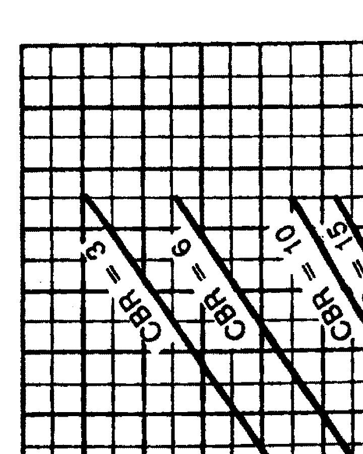
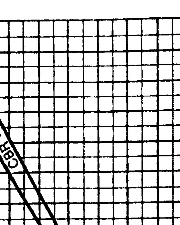
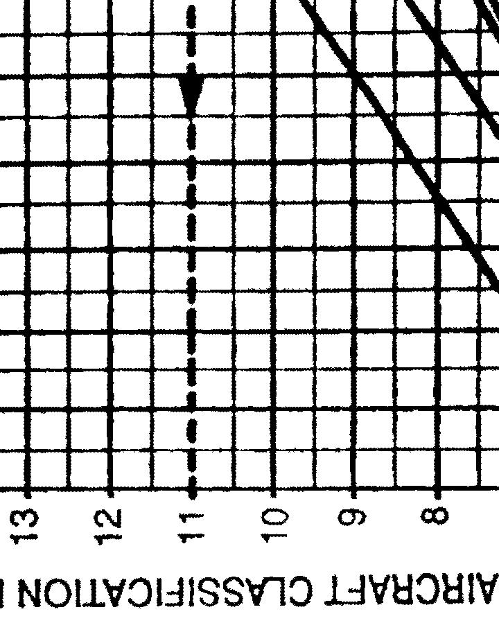
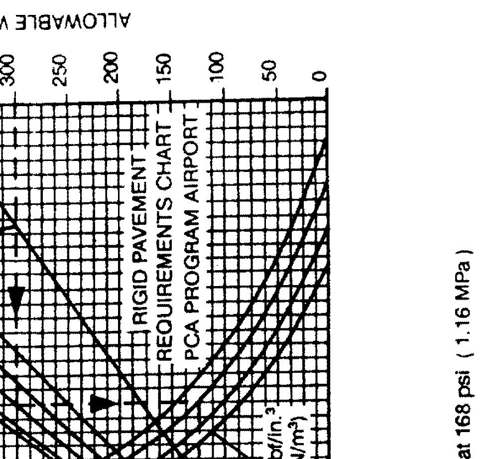
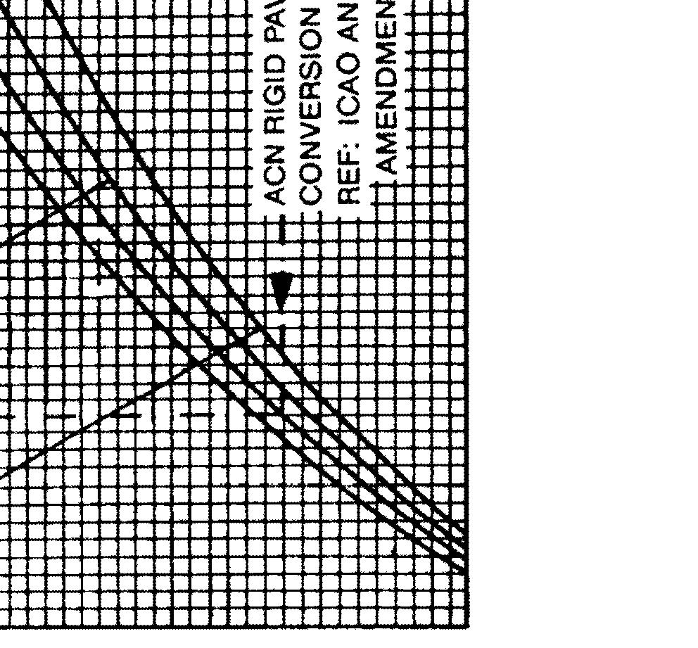
95 **ON A/C ALL PAVEMENT DATA 1. PAVEMENT DATA A. Section Contents/Chart Explanations This section provides information on a variety of pavement related data including; aircraft footprints, pavement loading during standard operations, and airplane/pavement rating systems. Figure 1 presents basic data on the landing gear footprint configuration, maximum design taxi loads and tire sizes and pressures. Maximum pavement loads for certain critical conditions at the tire-ground interfaces are shown in Figure 2. In the charts presented in Figure 3 to paragraph 3. each airplane configuration is depicted with a variety of standard operating loads imposed on the main landing gear to aid in the interpolation between the discrete values shown. All curves for any single chart represents data at a constant tire pressure which will produce a tire deflection of 32 percent at the maximum design taxi weight shown. Pavement requirements for commercial airplanes are customarily derived from the static analysis of loads imposed on the main landing gear struts. The chart in Figure 3 is provided in order to determine these loads throughout the stability limits of the airplane at rest on the pavement. These main landing gear loads are used to enter the pavement design charts which follow, interpolating load values where necessary. Rigid pavement design curves presented in Figure 5 have been prepared with the use of the Westergaard Equation in general accordance with the procedures outlined in the 1955 edition of "Design of Concrete Airport Pavement" published by the Portland Cement Association, 5420 Old Orchard Rd. Skokie, IL 60077, but modified to the new format described in the 1968 Portland Cement Association (PCA) publication, Operation Instructions "Computer Program for Concrete Airport Pavement Design" (Program PDILB) By Robert G. Packard. The following procedure is used to develop rigid pavement design curves shown in Figure 5. Having established the scale for pavement thickness to the left and the scale for the allowable working stress to the right, an arbitrary load line is drawn representing the main landing gear maximum weight to be shown. All values of the subgrade modulus (k-values) are then plotted. Additional load lines for the incremental values of weight on the main landing gear are then established on the basis of the curve for k=300 lbf/in 3 (80 MN/m 3 ), already established. All Load Classification Number (LCN) curves where shown have been plotted from data in the International Civil Aviation Organization (ICAO) Document 7290 AN/865/2, Aerodrome Manual, Part 2, "Aerodrome Physical Characteristics", 2nd Edition, Page 1
96 On the same charts showing LCN versus equivalent single wheel load (ESWL), there are load plots for the CL 600 2B19. The charts show the ESWL versus the pavement thickness for flexible pavements and versus the radius of relative stiffness for rigid pavements. Procedures and curves provided in the ICAO Aerodrome Manual Part 2, Chapter 4 are used to determine ESWL for use in making LCN conversion of rigid pavement requirements. NOTE: Pavement requirements are presented for loads, tires and tire pressures presently certified for commercial usage. All curves represent data at a constant specified tire pressure. The ACN/PCN system as referenced in Amendment 35 to ICAO Annex 14, "Aerodromes", 7th Edition, June 1976, provides a standardized international airplane/pavement rating system replacing the various S, T, TT, LCN, AUW, ISWL, etc., rating systems used throughout the world. Paragraph 5. introduces the basic ACN PCN (aircraft/pavement) rating system and analysis procedure. Paragraph 5.B. provides a quick reference table for ACN data for flexible pavements. This information is presented in a graph format in Figure 9. Background information on the determination of ACNs for flexible pavements is presented in paragraph 5.D. and Figure 11. Paragraph 5.C. provides a quick reference table for ACN data for rigid pavements. This information is presented in a graph format in Figure 10. Background information on the determination of ACNs for rigid pavements is presented in paragraph 5.E. and Figure Page 2
97 apm070200_01_fp_sept 11, 2015 Footprint Figure Page 3
98 apm070300_01_fp_sept 11, 2015 Maximum Pavement Load Figure Page 4
99 apm070400_01_fp_sept 11, 2015 Landing Gear Load on Pavement Figure Page 5
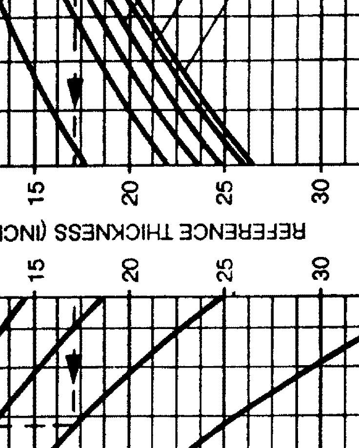
100 2. FLEXIBLE PAVEMENT REQUIREMENTS LCN CONVERSION In order to determine the airplane weight that can be accommodated on a particular flexible airport pavement, both the LCN of the pavement and the thickness (p) of the pavement must be known. In the example shown in Figure 4, the flexible pavement thickness = 10, and the LCN = 18. For this condition the weight on the main landing gear is pounds (8676 kg) Page 6


101 apm070501_01_fp_sept 11, 2015 Flexible Pavement Requirements LCN Conversion Figure Page 7


102 apm070600_01_fp_sept 11, 2015 Rigid Pavement Requirements Portland Association Design Figure Page 8
103 3. RIGID PAVEMENT REQUIREMENTS LCN CONVERSION In order to determine the airplane weight that can be accommodated on a particular rigid airport pavement, both the LCN of the pavement and the radius of relative stiffness must be known. In the example shown in Figure 7, the radius of relative stiffness = 30, and the LCN = 19. For these conditions the weight on the main landing gear is pounds (17352 kg) Page 9


104 apm070701_01_fp_sept 11, 2015 Radius of Relative Stiffness Table Figure Page 10
105 apm070702_01_fp_sept 11, 2015 Rigid Pavement Requirements LCN Conversion Figure Page 11
106 4. RADIUS OF RELATIVE STIFFNESS (OTHER VALUES of E and L) The table of Figure 8 presents L values based on Young s modulus (E) of psi and Poisson s ratio (μ) of For convenience in finding L values based on other values of E and μ, the curves of Figure 8 are included. For example, to find an L value based on an E of psi, the E factor is multiplied by the L value found in the table of Figure 8. The effect of variations of μ on the L value is treated in a similar manner Page 12
107 apm070704_01_fp_sept 11, 2015 Radius of Relative Stiffness Chart Figure Page 13
108 5. ACN PCN REPORTING SYSTEM The ACN value (Aircraft Classification Number) is a number which expresses the relative structural effect of an aircraft on different pavement types for specified standard subgrade strengths in terms of a standard single wheel load. The PCN value (Pavement Classification Number) is a number which expresses the relative load carrying capacity of a pavement in terms of a standard single wheel load. The computation of ACN values will rarely, if ever, be required by anyone other than aircraft manufacturers. Although ACN calculation materials are presented in this manual, airport planners are cautioned that these materials are not to be used to calculate ACNs. Pavement evaluation and calculation using the PCN method is, however, left to the airport planner. The eventual results of their evaluation appear as a PCN code combination with a numeric value followed by the PCN codes. Full PCN Code Format PCN Pavement Type Subgrade Category Tire Pressure Category Evaluation Method Numerical value R Rigid A High W No limit T Technical B Medium X To 217 psi (1.5 MPa) F Flexible C Low Y To 145 psi (1.0 MPa) U Using Aircraft D Ultra Low Z To 73 psi (0.5 MPa) The PCN value is for reporting pavement strength only. The PCN value cannot be used for pavement design or as a substitute for evaluation. Pavement design and evaluation are complex engineering problems which require detailed analysis. They cannot be reduced to a single number. Once a PCN number has been determined and published, it can be compared with an aircraft s ACN. An aircraft that has an ACN equal to or less than the PCN of a given pavement can operate without restriction on the pavement. (Ref: ICAO State Letter AN 4/ /9. Ref: US FAA Advisory Circular 150/ /06/83). A. Aircraft Parameters for ACN Determination The following parameters were used the determination of the ACNs of the Canadair Regional Jet Model CL 600 2B Page 14
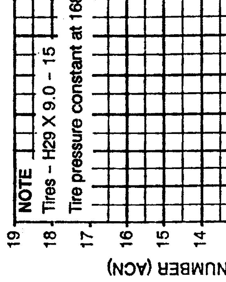
109 Aircraft Type Aircraft Weight Load on one main gear leg Standard Aircraft Tire pressure Loaded Unloaded lbs kgs % psi MPa psi MPa CRJ100/ CRJ100 ER/200 ER CRJ100 LR/200 LR B. ACN Quick Reference Table Flexible Pavement See paragraph 5.D. for more information on the development of ACNs for flexible pavement. Aircraft Type ACN relative to Flexible Pavement subgrades High Medium Low Very Low CBR=15% CBR=10% CBR=6% CBR=3% CRJ100/ CRJ100 ER/200 ER CRJ100 LR/200 LR C. ACN Quick Reference Table Rigid Pavement See paragraph 5.E. for more information on the development of ACNs for rigid pavement. Aircraft Type ACN relative to Rigid Pavement subgrades High Medium Low Very Low K=150 MN/m 2 K=80 MN/m 2 K=40 MN/m 2 K=20 MN/m 2 CRJ100/ CRJ100 ER/200 ER CRJ100 LR/200 LR Page 15
110 Aircraft Type ACN relative to Rigid Pavement subgrades High Medium Low Very Low K=150 MN/m 2 K=80 MN/m 2 K=40 MN/m 2 K=20 MN/m 2 NOTE: The ACN for the CJR100/200 standard version was calculated using a taxi weight of pounds ( kg). The published maximum taxi weight (MTW) of the CRJ100/200 is pounds ( kg) Page 16

111 apm070804_01_fp_sept 11, 2015 Aircraft Classification Number Flexible Pavement Chart Figure Page 17


112 apm070805_01_fp_sept 11, 2015 Aircraft Classification Number Rigid Pavement Chart Figure Page 18
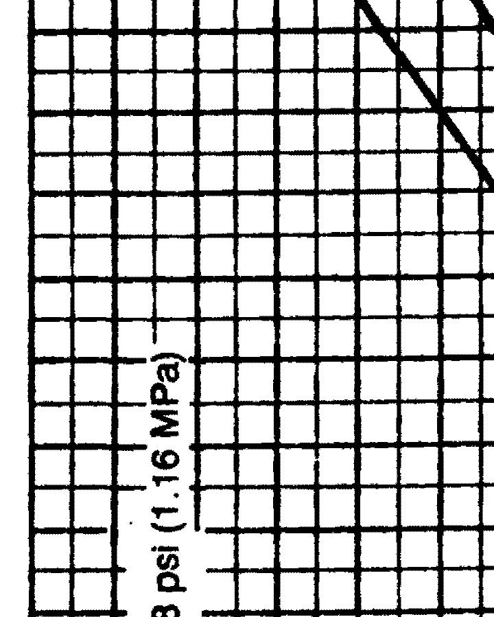
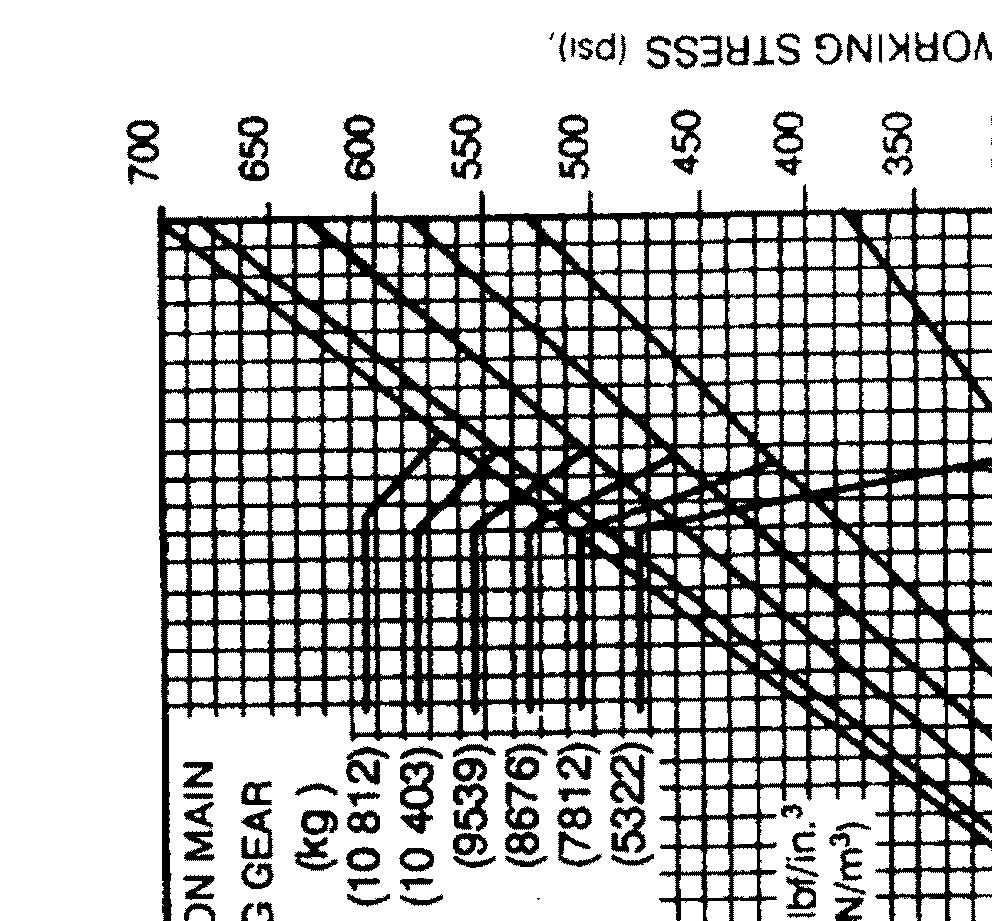
113 D. Development of ACN Flexible Pavement The following procedure is used to develop the flexible pavement ACN charts such as that shown in Figure 9. (1) Determine the percent of weight on the main gear to be used in steps (2), (3), and (4) below. It is the maximum aft center of gravity (cg) position which yields the critical loading on the critical gear Refer to Figure 3. This cg position is used to determine the main gear loads at all gross weights of the model being considered. (2) Establish a flexible pavement requirements chart using the S 77 1 design method such as shown on the right hand side of Figure 11. Use standard subgrade strengths of CBR 3, 5, 10, and 15 percent and coverages. (3) Determine reference thickness values from the pavement requirement chart of step (2) for each standard subgrade strength and gear loading. (4) Enter the reference thickness values into the ACN Flexible Pavement Conversion Chart shown on the left hand side of Figure 11 to determine the ACN. This chart was developed using the S 77 1 design method with a single tire inflated to 168 psi (1.16 MPa) pressure and coverages. The ACN is two times the derived single wheel load expressed in thousands of kilograms. These values of ACN are then plotted as a function of aircraft gross weight such as shown in Figure Page 19

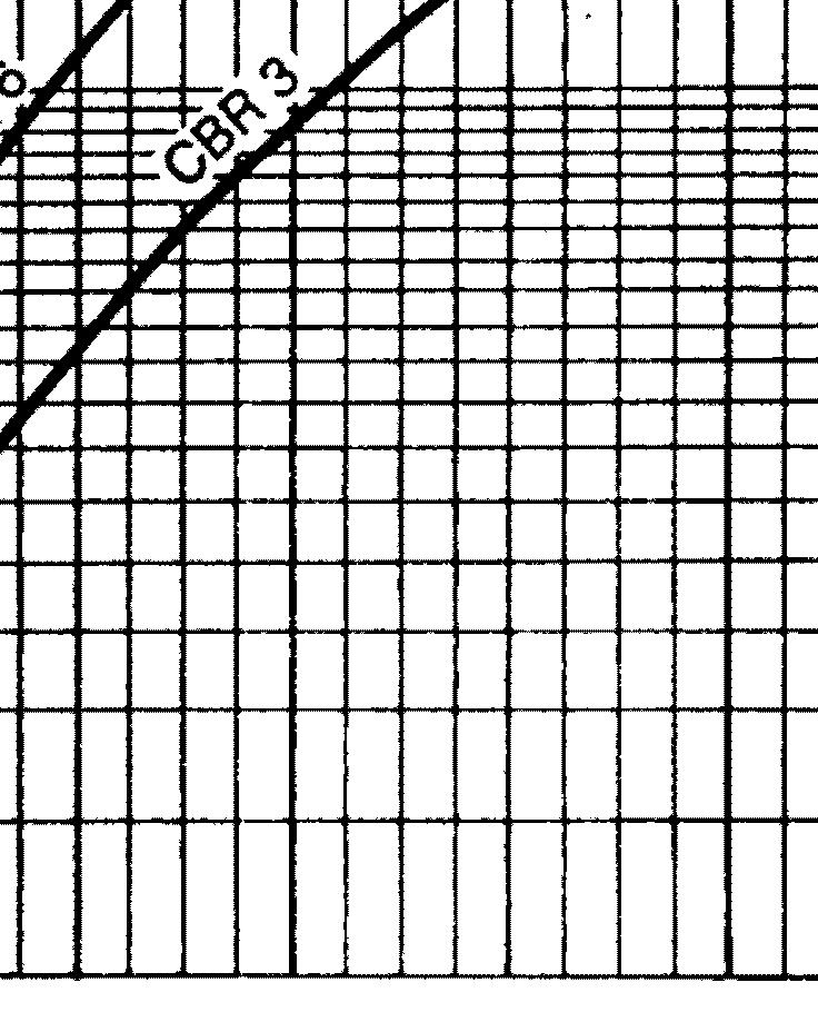
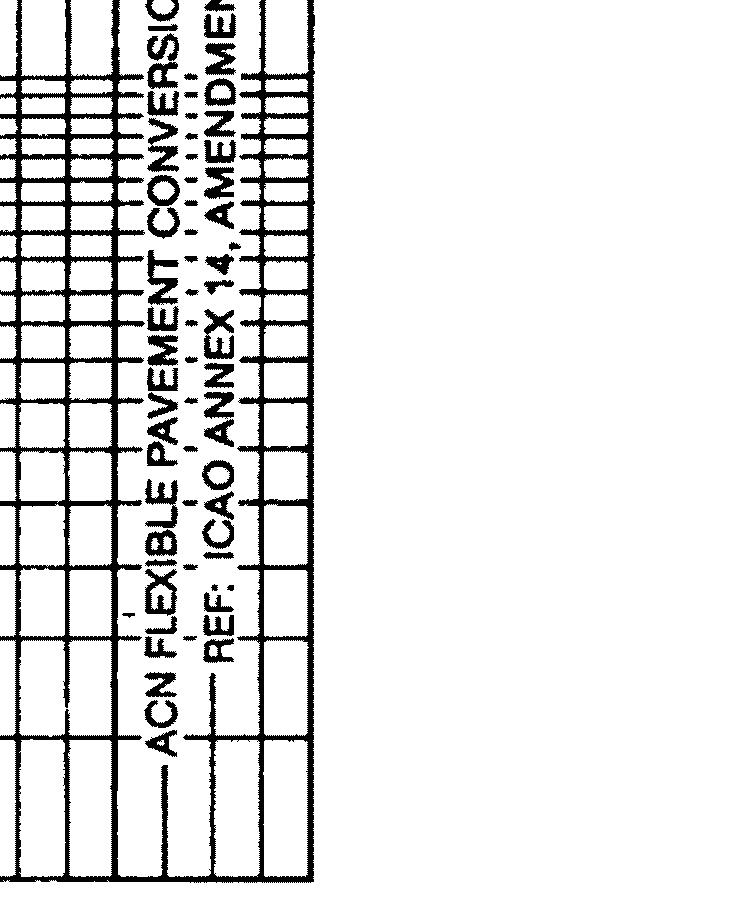
114 apm070807_01_fp_sept 11, 2015 Development of ACN Flexible Pavement Figure Page 20
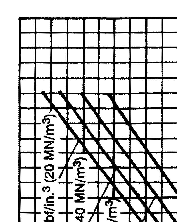
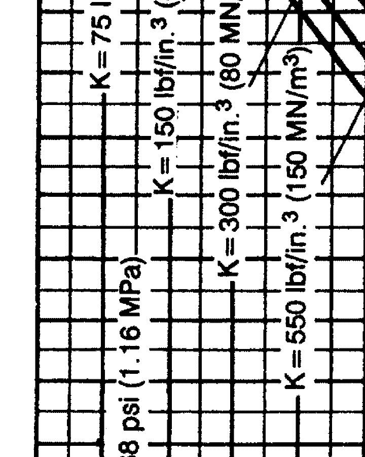
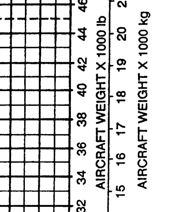
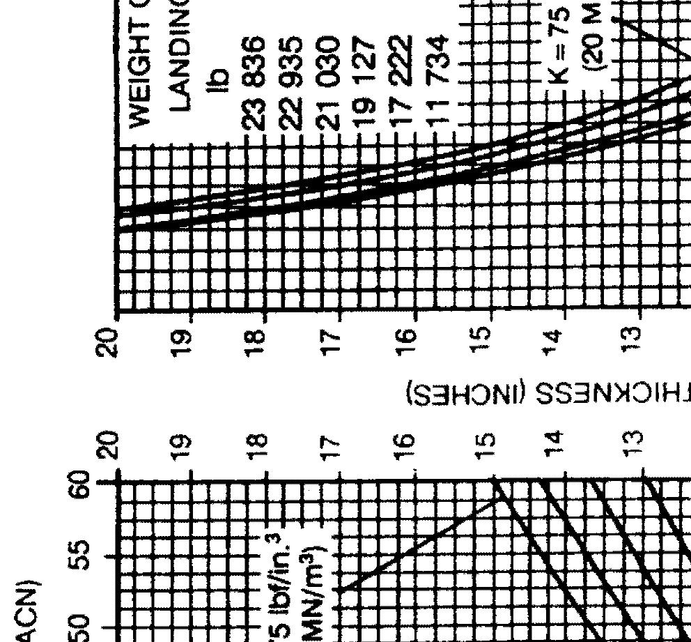
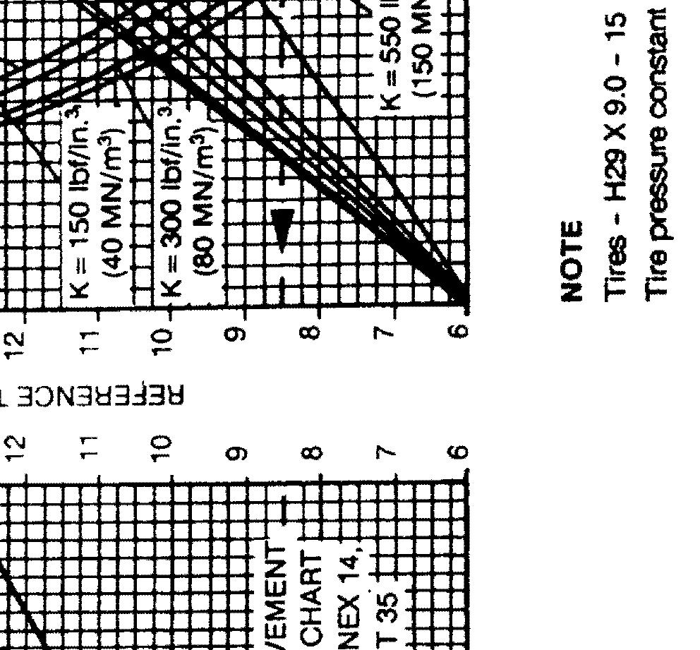
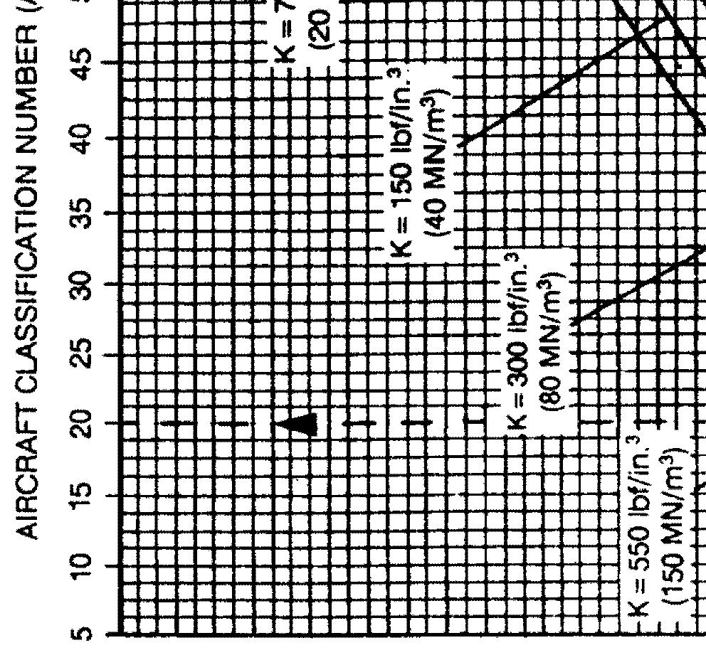
115 E. Development of ACN Charts Rigid Pavement The following procedure is used to develop the rigid pavement ACN chart shown in Figure 9. (1) Determine the percentage of weight on the main gear to be used in steps (2), (3), and (4). It is the maximum aft center of gravity (cg) position which yields the critical loading on the critical gear Refer to Figure 3. This cg position is used to determine main gear loads at all gross weights of the model being considered. (2) Establish a rigid pavement requirements chart using the PCA computer program PDILB shown on the right hand side of Figure 12. Use standard subgrade strengths of k = 75, 150, 300 and 550 lbf/in 3 (nominal values for k = 20, 40, 80 and 150 MN/m 3 ). This chart provides the same thickness values as that of Figure 5. (3) Determine reference thickness values from the pavement requirements chart of step (2) for each standard subgrade strength and gear loading at 300 psi working stress (nominal value for 2.07 MPa working stress). (4) Enter the reference thickness values into the ACN Rigid Pavement Conversion Chart shown on the left hand side of Figure 12 to determine ACN. This chart was developed using the PCA computer program PDILB with a single tire inflated to 168 psi (1.16 MPa) pressure and working stress of 300 psi (2.07 MPa). The ACN is twice the derived single wheel load expressed in thousands of kilograms. These values of ACN are then plotted as a function of aircraft gross weight as shown in Figure Page 21
116 apm070809_01_fp_sept 11, 2015 Development of ACN Rigid Pavement Chart Figure Page 22
117 **ON A/C ALL DERIVATIVE AIRCRAFT 1. DERIVATIVE AIRCRAFT Canadair Regional Jet Series 700. The CRJ700 is the most recent addition to the Canadair Regional Jet family. Although not a linear derivative of the CRJ100/200, the 70 passenger CRJ700 maintains significant design commonalities with the other members of the family, while offering greater range and increased passenger capacity. For more information on airport planning for the CRJ700, refer to the Canadair Regional Jet Series 700 Airport Planning Manual, or contact Bombardier Aerospace Regional Aircraft Page 1
118 THIS PAGE INTENTIONALLY LEFT BLANK
119 **ON A/C ALL SCALED DRAWINGS 1. SCALED DRAWINGS This section contains the scaled drawings. They can be used to plan and to verify runway, ramp and maintenance facility layouts. Refer to Figure 1 for the US Standard scaled drawing. Refer to Figure 2 for the Metric scaled drawing Page 1
120 apm090100_01_fp_sept 11, 2015 Scaled Drawing (US Standard) Figure Page 2
121 apm090200_01_fp_sept 11, 2015 Scaled Drawing (Metric) Figure Page 3
122 THIS PAGE INTENTIONALLY LEFT BLANK
7.1 General Information. 7.2 Landing Gear Footprint. 7.3 Maximum Pavement Loads. 7.4 Landing Gear Loading on Pavement
 7.0 PAVEMENT DATA 7.1 General Information 7.2 Landing Gear Footprint 7.3 Maximum Pavement Loads 7.4 Landing Gear Loading on Pavement 7.5 Flexible Pavement Requirements - U.S. Army Corps of Engineers Method
/300 Airplane Characteristics for Airport Planning
 777-200/300 Airplane Characteristics for Airport Planning Boeing Commercial Airplanes OCTOBER 2004 i THIS PAGE INTENTIONALLY LEFT BLANK ii OCTOBER 2002 777 AIRPLANE CHARACTERISTICS LIST OF ACTIVE PAGES
/300 Airplane Characteristics for Airport Planning
 757-200/300 Airplane Characteristics for Airport Planning Boeing Commercial Airplanes AUGUST 2002 i THIS PAGE INTENTIONALLY LEFT BLANK ii AUGUST 2002 757 AIRPLANE CHARACTERISTICS LIST OF ACTIVE PAGES Page
767 Airplane Characteristics for. Airport Planning. Boeing Commercial Airplanes. D SEPTEMBER 2005 i
 767 Airplane Characteristics for Airport Planning Boeing Commercial Airplanes SEPTEMBER 2005 i 767 AIRPLANE CHARACTERISTICS FOR AIRPORT PLANNING LIST OF ACTIVE PAGES Page Date Page Date Page Date Original
737 MAX Airplane Characteristics for Airport Planning
 CAGE Code 81205 737 MAX Airplane Characteristics for Airport Planning DOCUMENT NUMBER: REVISION: REVISION DATE: REV NEW July 2015 CONTENT OWNER: Boeing Commercial Airplanes All revisions to this document
737 Airplane Characteristics for Airport Planning
 737 Airplane Characteristics for Airport Planning Boeing Commercial Airplanes OCTOBER 2005 i TABLE OF CONTENTS SECTION TITLE PAGE 1.0 SCOPE AND INTRODUCTION 1 1.1 Scope 2 1.2 Introduction 3 1.3 A Brief
777-9 Airplane Characteristics for Airport Planning
 CAGE Code 81205 777-9 Airplane Characteristics for Airport Planning DOCUMENT NUMBER: REVISION: REVISION DATE: REV A March 2018 CONTENT OWNER: Boeing Commercial Airplanes All revisions to this document
Airport Compatibility Brochure 737 MAX
 Airport Compatibility Brochure 737 MAX Specific airport compatibility questions concerning Boeing commercial aircraft should be forwarded to: June 2017 BOEING is a trademark of Boeing Management Company.
Airport Compatibility
 747X Quiet Longer Range Family Airport Compatibility April, 2002 Specific airport compatibility questions concerning commercial aircraft should be forwarded to: Airport Technology Boeing (Seattle, WA)
Bearing Strength Assessment PLR & PCN
 1 LEISMER AIRPORT (Airport code CET2, Canada) Bearing Strength Assessment PLR & PCN Report APMS-111021 October 21, 2011 APMS Stationsweg 51, Velsen-Zuid 1981 BA, the Netherlands Phone: + 31 (0) 255 524
Boeing Aircraft and the Impact on Airports
 International Civil Aviation Organization on Pavement Management Systems Lima, Peru November 19-22, 2003 Boeing Aircraft and the Impact on Airports Orest Shepson Principal Engineer - Airport Technology
2.1 General Characteristics. 2.2 General Dimensions. 2.3 Ground Clearances. 2.4 Interior Arrangements. 2.5 Cabin Cross Sections
 2.0 AIRPLANE DESCRIPTION 2.1 General Characteristics 2.2 General Dimensions 2.3 Ground Clearances 2.4 Interior Arrangements 2.5 Cabin Cross Sections 2.6 Lower Cargo Compartments 2.7 Door Clearances JUNE
@AIRBUS A /-600 AIRCRAFT CHARACTERISTICS AIRPORT AND MAINTENANCE PLANNING
 @AIRBUS A340-500/-600 AIRCRAFT CHARACTERISTICS AIRPORT AND MAINTENANCE PLANNING AC The content of this document is the property of Airbus. It is supplied in confidence and commercial security on its contents
Airport Compatibility Brochure 737 MAX. March 2014 PRELIMINARY
 Airport Compatibility Brochure 737 MAX March 2014 BOEING is a trademark of Boeing Management Company. Copyright 2013 Boeing. All rights reserved. PRELIMINARY Specific airport compatibility questions concerning
NOTE: DATA PRELIMINARY
 2.0 AIRPLANE DESCRIPTION 2.1 General Characteristics 2.2 General Dimensions 2.3 Ground Clearances 2.4 Interior Arrangements 2.5 Cabin Cross Sections 2.6 Lower Cargo Compartments 2.7 Door Clearances REV
Tires Versus Pavement: Pilots, mechanics, and airport managers on the same page
 Tires Versus Pavement: Pilots, mechanics, and airport managers on the same page Pilots often think tire pressure and condition are a mechanic s worry, not theirs. Similarly, the pavement strength of the
TAKEOFF SAFETY ISSUE 2-11/2001. Flight Operations Support & Line Assistance
 TAKEOFF SAFETY T R A I N I N G A I D ISSUE 2-11/2001 Flight Operations Support & Line Assistance Flight Operations Support & Line Assistance Introduction The purpose of this brochure is to provide the
Runway Length Analysis Prescott Municipal Airport
 APPENDIX 2 Runway Length Analysis Prescott Municipal Airport May 11, 2009 Version 2 (draft) Table of Contents Introduction... 1-1 Section 1 Purpose & Need... 1-2 Section 2 Design Standards...1-3 Section
Boeing Airplane Overview
 Boeing Airplane Overview Yonglian Ding, PE Boeing Airport Compatibility Engineering Nov 29, 2016 BOEING is a trademark of Boeing Management Company. Copyright 2016 Boeing. All rights reserved. Agenda Aircraft
CESSNA SECTION 5 PERFORMANCE
 CESSNA SECTION 5 TABLE OF CONTENTS Page Introduction............................................5-3 Use of Performance Charts................................5-3 Sample Problem........................................5-4
Airport Compatibility
 Presented by Dan COHEN-NIR Programs Director Airbus Americas Holdings Inc. www.airbusamericas.com Airport Compatibility Opportunities and Challenges Airport Challenges & Aircraft Design Challenge: Prepare
717 Aeroplane JAA Data Sheet
 The Following Content of this Data Sheet is Complete In Accordance With the Concurrent and Cooperative Certification Process (CCC) Working Procedure, Draft Issue 8 dated 17-May-1994 and JAA Administrative
Airplane Performance. Introduction. Copyright 2017 Boeing. All rights reserved.
 Introduction Airplane Performance The statements contained herein are based on good faith assumptions and provided for general information purposes only. These statements do not constitute an offer, promise,
USE OF TAKEOFF CHARTS [B737]
![USE OF TAKEOFF CHARTS [B737]](/thumbs/84/90602989.jpg "USE OF TAKEOFF CHARTS [B737]") USE OF TAKEOFF CHARTS [B737] 1. Introducton This documentation presents an example of takeoff performance calculations for Boeing 737. It is called self-dispatch, primarily used by airline crew if that
USE OF TAKEOFF CHARTS [B737] 1. Introducton This documentation presents an example of takeoff performance calculations for Boeing 737. It is called self-dispatch, primarily used by airline crew if that
Worldwide Aircraft Services, Inc
 Worldwide Aircraft Services, Inc Worldwide Aircraft Services, Inc. Springfield / Branson Regional Airport 2755 N. General Aviation Ave., Springfield, Missouri 65803 (417) 865-1879 # 0r Fax (417) 865-6884
Chapter 14. Design of Flexible Airport Pavements AC 150/5320-6D
 Chapter 14 Design of Flexible Airport Pavements AC 150/5320-6D AIRCRAFT CONSIDERATIONS. a. Load. maximum anticipated takeoff weight of the aircraft. The design procedure assumes 95 percent of the gross
The Aircraft Classification Rating Pavement Classification Rating ACR-PCR
 XIV Seminario ALACPA de Pavimentos Aeroportuarios XII Taller Federal Aviation Administration VII Curso Rápido de Mantenimiento de Pavimentos de Aeródromos 28/05 al 01/06 2018 Ciudad de Quito - Ecuador
According to FAA Advisory Circular 150/5060-5, Airport Capacity and Delay, the elements that affect airfield capacity include:
 4.1 INTRODUCTION The previous chapters have described the existing facilities and provided planning guidelines as well as a forecast of demand for aviation activity at North Perry Airport. The demand/capacity
APPENDIX X: RUNWAY LENGTH ANALYSIS
 APPENDIX X: RUNWAY LENGTH ANALYSIS Purpose For this Airport Master Plan study, the FAA has requested a runway length analysis to be completed to current FAA AC 150/5325-4B, Runway Length Requirements for
FOR REFERENCE ONLY NOT FOR FLIGHT
 PIPER AIRCRAFT CORPORATION SECTION 6 6.7 GENERAL LOADING RECOMMENDATIONS For all airplane configurations, it is the responsibility of the pilot in command to make sure that the airplane always remains
Assignment 3: Runway Length and EMAS Design. Aircraft Engine Remarks. CFM56-7B20/-7B22/-7B24 developing 20,000 lb of thrust at sea level
 CEE 4674: Airport Planning and Design Spring 2014 Solution! Assignment 3: Runway Length and EMAS Design Instructor: Trani Problem 1 A new airport to be constructed near Mexico City airport would like to
FUEL MANAGEMENT FOR COMMERCIAL TRANSPORT
 FUEL MANAGEMENT FOR COMMERCIAL TRANSPORT 1. Introduction An aeroplane shall carry a sufficient amount of usable fuel to complete the planned flight safely and to allow for deviation from the planned operation.
CHAPTER 2 AIRCRAFT INFORMATION SUMMARY TABLE OF CONTENTS
 CHAPTER 2 AIRCRAFT INFORMATION SUMMARY TABLE OF CONTENTS General...2 Kinds of Operations...2 Structural and weight limitations...2 Maneuvering limitations...3 Flight load factor limitations...3 Power plant
COMFAA. Acknowledgments. Demonstration and. Rapol, FAA. Ken DeBord and Mike Roginski, Boeing Commercial Airplane Co. Federal Aviation Administration
 COMFAA Demonstration and Hands-On Training Presented to: VII ALACPA Airport Pavement Seminar & V FAA Airport Pavement Workshop By: David R. Brill, P.E., Ph.D. Date: Acknowledgments Gordon Hayhoe, Rodney
PHENOM 300 TYPE CERTIFICATE
 PHENOM 300 TYPE CERTIFICATE PROGRAM UPDATE AND DEVELOPMENT HIGHLIGHTS THE INFORMATION HEREIN IS SUBJECT TO THE DISCLAIMER PRESENTED IN THE LAST PAGE OF THIS DOCUMENT. THIS PRESENTATION IS THE THE INFORMATION
3.1 General Information. 3.2 Payload/Range for 0.85 Mach Cruise. 3.3 F.A.R. Takeoff Runway Length Requirements
 3.0 AIRPLANE PERFORMANCE 3.1 General Information 3.2 Payload/Range for 0.85 Mach Cruise 3.3 F.A.R. Takeoff Runway Length Requirements 3.4 F.A.R. Landing Runway Length Requirements DECEMBER 2002 53 3.0
FORT LAUDERDALE-HOLLYWOOD INTERNATIONAL AIRPORT ENVIRONMENTAL IMPACT STATEMENT DRAFT
 D.3 RUNWAY LENGTH ANALYSIS Appendix D Purpose and Need THIS PAGE INTENTIONALLY LEFT BLANK Appendix D Purpose and Need APPENDIX D.3 AIRFIELD GEOMETRIC REQUIREMENTS This information provided in this appendix
DEPARTMENT OF TRANSPORTATION FEDERAL AVIATION ADMINISTRATION FAA TYPE CERTIFICATE DATA SHEET NO. A55NM
 DEPARTMENT OF TRANSPORTATION FEDERAL AVIATION ADMINISTRATION A55NM Revision 7 328 Support Services GmbH Dornier Model 328-300 September 8, 2016 FAA TYPE CERTIFICATE DATA SHEET NO. A55NM This data sheet
Noise Certification Workshop
 Session 2: Aircraft Noise Certification Harmonisation James Skalecky U.S. FAA 1 Harmonisation / The Beginning In June 1990 at a meeting of the JAA Council and the FAA, the FAA Administrator committed the
Draft Proposal for the Amendment of the Sub-Cap on Off-Peak Landing & Take Off Charges at Dublin Airport. Addendum to Commission Paper CP4/2003
 Draft Proposal for the Amendment of the Sub-Cap on Off-Peak Landing & Take Off Charges at Dublin Airport Addendum to Commission Paper CP4/2003 26 th November 2003 Commission for Aviation Regulation 3 rd
GAR-AERO WHEEL ADAPTERS & TIRES
 FOUND FBA-2C2 SUPPLEMENT M400-S03 Transport Canada Approved Flight Manual Supplement For GAR-AERO WHEEL ADAPTERS & This supplemental manual is applicable to Gar-Aero Wheel Adapters & 8.50-10 tires equipped
The Boeing Next-Generation 737 Family Productive, Progressive, Flexible, Familiar
 Backgrounder Boeing Commercial Airplanes P.O. Box 3707 MC 21-70 Seattle, Washington 98124-2207 www.boeing.com The Boeing Next-Generation 737 Family Productive, Progressive, Flexible, Familiar The members
Accident Prevention Program
 Accident Prevention Program WEIGHT AND BALANCE An Important Safety Consideration for Pilots Aircraft performance and handling characteristics are affected by the gross weight and center of gravity limits.
DEPARTMENT OF TRANSPORTATION FEDERAL AVIATION ADMINISTRATION. TYPE CERTIFICATE DATA SHEET No. A00006WI
 DEPARTMENT OF TRANSPORTATION FEDERAL AVIATION ADMINISTRATION A00006WI Revision 6 HAIC Y12 IV Y12E February 7, 2013 TYPE CERTIFICATE DATA SHEET No. A00006WI This data sheet, which is part of Type Certificate
1.0 SCOPE AND INTRODUCTION. 1.1 Scope. 1.2 Introduction. 1.3 A Brief Description of the
 1.0 SCOPE AND INTRODUCTION 1.1 Scope 1.2 Introduction 1.3 A Brief Description of the 747-400 DECEMBER 2002 1 1.0 SCOPE AND INTRODUCTION 1.1 Scope This document provides, in a standardized format, airplane
DEPARTMENT OF TRANSPORTATION FEDERAL AVIATION ADMINISTRATION FAA TYPE CERTIFICATE DATA SHEET NO. A45NM
 DEPARTMENT OF TRANSPORTATION FEDERAL AVIATION ADMINISTRATION A45NM Revision 8 328 Support Services GmbH Dornier Model 328-100 September 9, 2016 FAA TYPE CERTIFICATE DATA SHEET NO. A45NM This data sheet
FOR REFERENCE ONLY NOT FOR FLIGHT
 PA-46-350P, MALIBU SECTION 6 6.7 GENERAL LOADING RECOMMENDATIONS For all airplane configurations, it is the responsibility of the pilot in command to make sure that the airplane always remains within the
Valley Fliers 1402 Auburn Way North, #223 Auburn WA 98002
 Valley Fliers 1402 Auburn Way North, #223 Auburn WA 98002 Instructor: Check Out Date: Phase 1: Pre-Flight Name: Certificate Number: Certificate Type: Ratings: Total Flight Time: Last 90 Days: Club check
Glossary. basic empty weight (GAMA). Standard empty weight plus optional equipment.
. Standard empty weight plus optional equipment.") Glossary General Aviation Manufacturers Association (GAMA) 14 CFR, Part 121. The Federal regulations governing domestic, flag, and supplemental operations. 14 CFR, Part 135. The Federal regulations governing
Glossary General Aviation Manufacturers Association (GAMA) 14 CFR, Part 121. The Federal regulations governing domestic, flag, and supplemental operations. 14 CFR, Part 135. The Federal regulations governing
PROPOSED HORIZONTAL LAYOUT FILLET DESIGN FOR ENTRANCE/EXIT TAXIWAYS
 PROPOSED HORIZONTAL LAYOUT FILLET DESIGN FOR ENTRANCE/EXIT TAXIWAYS INTRODUCTION The Zelienople Airport Authority (ZAA) has commenced engineering activities for the rehabilitation of Runway 17-35 to a
REPORT No.: 190NOY015. TITLE: Embraer 190 Noise Levels - Technical Substantiation for Bromma Airport Operation ATA 2200 No.
 Page: 1 of 33 ISSUED BY: EMBRAER VEC//GIR/0002 REPORT No.: 190NOY015 PROGRAM: E-Jets TITLE: Embraer 190 Noise Levels - Technical Substantiation for Bromma Airport Operation ATA 2200 No.: Not applicable
CESSNA CITATION IIB PW JT15D-4 INTRODUCTION. Runway Analysis provides the means to determine maximum allowable takeoff and landing weights based upon:
 CESSNA CITATION IIB PW JT15D-4 INTRODUCTION Runway Analysis provides the means to determine maximum allowable takeoff and landing weights based upon: Airport characteristics consisting of airport elevation,
PCN Reporting- Current Problems and Future Research Plans
 PCN Reporting- Current Problems and Future Research Plans Michael J. Roginski, P.E. Principal Engineer Boeing Airport Compatibility Engineering, Pavement Lead October 1-4, 2013 Mexico City, Mexico BOEING
SECTION B AIRWORTHINESS CERTIFICATION
 SECTION B AIRWORTHINESS CERTIFICATION 1 2 NEPALESE CIVIL AIRWORTHINESS REQUIREMENTS SECTION B AIRWORTHINESS CERTIFICATION CHAPTER B.1 ISSUE 4 JANUARY 2009 1. INTRODUCTION TYPE CERTIFICATES 1.1 Before a
Advisory Circular. 1.1 Purpose Applicability Description of Changes... 2
 Advisory Circular Subject: Issuing Office: Standards Document No.: AC 521-006 File Classification No.: Z 5000-34 Issue No.: 01 RDIMS No.: 5611040-V40 Effective Date: 2012-03-16 1.1 Purpose... 2 1.2 Applicability...
Consideration will be given to other methods of compliance which may be presented to the Authority.
 Advisory Circular AC 139-11 Revision 2 Use of day-vfr aerodromes 27 April 2007 General Civil Aviation Authority advisory circulars (AC) contain information about standards, practices and procedures that
European Aviation Safety Agency
 TCDS No.: EASA.IM.A.210 DC-10, MD-11 Page 1 of 19 European Aviation Safety Agency EASA TYPE-CERTIFICATE DATA SHEET No. EASA.IM.A.210 for DC-10 / MD-11 Type Certificate Holder: Boeing The Boeing Company
PERFORMANCE AND TECHNOLOGY
 PERFORMANCE AND TECHNOLOGY Technology INNOVATION AT WORK. Every advanced feature carefully pursued to reduce pilot workload and improve situational awareness. ADVANCED FLIGHT DECK Featuring the Rockwell
Cessna 182R Initial Quiz Tail: N2365C Engine manufacturer, RPM. 7. How many fuel system drains are there?, where are they located?
 PILOT INSTRUCTOR_ DATE Cessna 182R Initial Quiz Tail: N2365C 04-17-08 Maximum normal category takeoff gross weight: lbs. Useful normal category load: lbs. Empty weight: lbs. What is the maximum landing
TYPE-CERTIFICATE DATA SHEET
 TYPE-CERTIFICATE DATA SHEET NO. EASA.A.644 for WT9 Dynamic LSA Type Certificate Holder Aerospool, spol. s r. o. Letisková 10, 971 03 Prievidza Slovak Republic For models: Club TE.CERT.00048-001 European
CRUISE TABLE OF CONTENTS
 CRUISE FLIGHT 2-1 CRUISE TABLE OF CONTENTS SUBJECT PAGE CRUISE FLIGHT... 3 FUEL PLANNING SCHEMATIC 737-600... 5 FUEL PLANNING SCHEMATIC 737-700... 6 FUEL PLANNING SCHEMATIC 737-800... 7 FUEL PLANNING SCHEMATIC
FAA Technical Documentation Requirements
 FAA Technical Documentation Requirements 1. A COMPLETED FAA Form 8130-6 or FAA Form 8130-1. The 8130-6 form is used to apply for a standard and special airworthiness certification, and the 8130-1 form
Weight and Balance User Guide
 Weight and Balance User Guide Selecting the Weight and Balance tab brings up the Departure and Destination screen, used for initiating the process for a standalone WB report. Select the tail to be used
The offers operators increased capacity while taking advantage of existing airport infrastructure. aero quarterly qtr_03 10
 The 747 8 offers operators increased capacity while taking advantage of existing airport infrastructure. 14 aero quarterly qtr_03 10 Operating the 747 8 at Existing Airports Today s major airports are
FLIGHT AND OPERATING MANUAL SUPPLEMENT FMS305902, REVISION 1 SEAPLANES WEST INC.
 FLIGHT AND OPERATING MANUAL SUPPLEMENT FMS305902, REVISION 1 AEROCET 3500/3500L FLOAT INSTALLATION ON CESSNA 182E THROUGH 182N AIRCRAFT AIRCRAFT MODEL: AIRCRAFT REGISTRATION: AIRCRAFT SERIAL NUMBER: TRANSPORT
Transportation Engineering -II Dr. Rajat Rastogi Department of Civil Engineering Indian Institute of Technology - Roorkee
 Transportation Engineering -II Dr. Rajat Rastogi Department of Civil Engineering Indian Institute of Technology - Roorkee Lecture - 36 Aprons & Aircraft Parking Dear students, today s lecture we are going
TYPE CERTIFICATE DATA SHEET No. A62EU
 DEPARTMENT OF TRANSPORTATION FEDERAL AVIATION ADMINISTRATION A62EU Revision 4 DORNIER SEASTAR Seastar CD2 March 2, 2007 TYPE CERTIFICATE DATA SHEET No. A62EU This data sheet which is part of Type Certificate
DEPARTMENT OF TRANSPORTATION FEDERAL AVIATION ADMINISTRATION TYPE CERTIFICATE DATA SHEET NO. A51NM East Falcon Drive Mesa, Arizona 85215
 DEPARTMENT OF TRANSPORTATION FEDERAL AVIATION ADMINISTRATION A51NM Marsh Aviation Company S2F-3T May 21, 1999 TYPE CERTIFICATE DATA SHEET NO. A51NM This data sheet, which is a part of Type Certificate
Quiet Climb. 26 AERO First-Quarter 2003 January
 Quiet Climb Boeing has developed the Quiet Climb System, an automated avionics feature for quiet procedures that involve thrust cutback after takeoff. By reducing and restoring thrust automatically, the
TYPE-CERTIFICATE DATA SHEET
 TYPE-CERTIFICATE DATA SHEET NO. EASA.A.573 for Virus SW 121 Type Certificate Holder Pipistrel d.o.o. Ajdovščina Goriška cesta 50A 5270 Ajdovščina Slovenia, Europe For models: Virus SW 121 TE.CERT.00048-001
BEDEK Aviation Group
 BEDEK Aviation Group B737NG CARGO CONVERSION PROGRAM This document contains proprietary information of Israel Aerospace Industries Ltd. and may not be reproduced, copied, disclosed or utilized in any way
SECTION 2 LIMITATIONS
 SECTION 2 LIMITATIONS TABLE OF CONTENTS Introduction... 3 Airspeed Limitations... 4 Airspeed Indicator Markings... 4 Powerplant Limitations... 5 Operations:... 5 Oil Limitation:... 5 Cylinder Head Temperature
TYPE CERTIFICATE DATA SHEET A3WE
 DEPARTMENT OF TRANSPORTATION FEDERAL AVIATION ADMINISTRATION A3WE Revision 19 BOEING 727 Series 727-100 Series 727C Series 727-100C Series 727-200 Series 727-200F Series February 20, 1991 TYPE CERTIFICATE
Appendix 5 Supplemental Noise and Aircraft Substitution
 Appendix 5 Supplemental Noise and Aircraft Substitution Appendix Integrated Noise Model Substitutions Summary The FAA s Integrated Noise Model (INM), Version 7.d, was used to generate aircraft noise exposure
SERVICE BULLETIN REVISION
 Revision 3 REVISION TRANSMITTAL SHEET This sheet transmits Revision 3 to which: A. Removes the NOTE from the Effectivity section. B. Adds a NOTE to the Reason section. C. Changes SB750-76-06 to SB750-76-07
TYPE CERTIFICATE DATA SHEET
 TYPE CERTIFICATE DATA SHEET N EASA.R.125 for SA 341 Type Certificate Holder Airbus Helicopters 13725 Marignane CEDEX France For Models: SA 341 G, SA 342 J TE.CERT.00049-001 European Aviation Safety Agency,
Taxiway Pavement Evaluation to Support the Operational of Terminal 2 Juanda Airport
 Regional Conference in Civil Engineering (RCCE) 634 Taxiway Pavement Evaluation to Support the Operational of Terminal 2 Juanda Airport Istiar 1*, Indrasurya B. Mochtar 1, Wahyu Herijanto 1, Catur Arif
TYPE-CERTIFICATE DATA SHEET
 TYPE-CERTIFICATE DATA SHEET NO. EASA.IM.A.053 for Type Certificate Holder: Textron Aviation Inc. One Cessna Boulevard Wichita, Kansas 67215 USA For models: 206H T206H TE.CERT.00048-001 European Aviation
CHAPTER 22 WEIGHT CONTROL OF AIRCRAFT
 May 2016 Page 1 of 8 CHAPTER 22 WEIGHT CONTROL OF AIRCRAFT 1. Introduction 1.1. The mass and centre of gravity of aircraft should be determined prior to the initial issuance of the Certificate of Airworthiness.
Daher s TBM 930 makes its mark in the charter sector
 Press release Daher s TBM 930 makes its mark in the charter sector Orlando, Florida, USA, October 15, 2018 The growing use of Daher s TBM very fast turboprop aircraft in charter services is being highlighted
Diamond Aircraft Industries GmbH N.A. Otto-Str.5 A-2700 Wiener Neustadt Austria
 DEPARTMENT OF TRANSPORTATION FEDERAL AVIATION ADMINISTRATION A47CE Revision 12 DIAMOND DA 40 DA 40 F DA 40 NG FEB 21, 2014 TYPE CERTIFICATE DATA SHEET NO. A47CE This data sheet which is part of Type Certificate
Type Acceptance Report
 TAR 13/21B/8 PIPER PA-20 Aircraft Certification Unit TABLE OF CONTENTS EXECUTIVE SUMMARY 1 1. INTRODUCTION 1 2. ICAO TYPE CERTIFICATE DETAILS 1 3. TYPE ACCEPTANCE DETAILS 1 4. NZCAR 21.43 DATA REQUIREMENTS
BDSF SPECIAL FREIGHTER CONVERSION
 phone: 407.517.0300 email: freighters@cargoleasing.com web: www.cargoleasing.com 767-300BDSF SPECIAL FREIGHTER CONVERSION Aircraft Length vs 767-200 FWD PLUG (121 ) AFT PLUG (132 ) MAIN DECK CARGO DOOR
TRANSMITTAL SHEET. Concurrent Requirement Added G450 Customer Bulletin Number 141 (aircraft that have previously incorporated ASC 016)
") TRANSMITTAL SHEET This sheet transmits Revision A, dated, to Gulfstream G450 Aircraft Service Change 016, dated August 18, 2005, titled Aircraft General (ATA 00) Maximum Takeoff Gross Weight (MTOGW) Increase.
TRANSMITTAL SHEET This sheet transmits Revision A, dated, to Gulfstream G450 Aircraft Service Change 016, dated August 18, 2005, titled Aircraft General (ATA 00) Maximum Takeoff Gross Weight (MTOGW) Increase.
Advisory Circular (AC)
") Advisory Circular (AC) Certification of Transport Category Aeroplanes On Narrow Runways File No. 5009-6-525 AC No. 525-014 RDIMS No. 528471-V3 Issue No. 01 Issuing Branch Aircraft Certification Effective
Advisory Circular (AC) Certification of Transport Category Aeroplanes On Narrow Runways File No. 5009-6-525 AC No. 525-014 RDIMS No. 528471-V3 Issue No. 01 Issuing Branch Aircraft Certification Effective
PRESOLO WRITTEN EXAM
 PRESOLO WRITTEN EXAM Date of Exam STUDENT INFORMATION Student Name Student Pilot Certificate Number FLIGHT INSTRUCTOR INFORMATION Instructor Instructor Certificate Number 1 INTRODUCTION Student Actions:
DEPARTMENT OF TRANSPORTATION FEDERAL AVIATION ADMINISTRATION TYPE CERTIFICATE DATA SHEET NO. A37CE
 DEPARTMENT OF TRANSPORTATION FEDERAL AVIATION ADMINISTRATION A37CE Revision 22 Textron Aviation Inc. 208 208B October 31, 2017 TYPE CERTIFICATE DATA SHEET NO. A37CE This data sheet which is part of Type
Type Acceptance Report
 TAR 98/08 Revision 1 CESSNA 150/152 Aircraft Certification Unit TABLE OF CONTENTS EXECUTIVE SUMMARY 1 1. INTRODUCTION 1 2. ICAO TYPE CERTIFICATE DETAILS 1 3. TYPE ACCEPTANCE DETAILS 1 4. NZCAR 21.43 DATA
Pilatus Aircraft Ltd. P.O. Box 992 CH-6371 Stans SWITZERLAND
 1 of 6 This data sheet which is part of Type Certificate No. F 56-20 prescribes conditions and limitations under which the product for which the type certificate was issued meets the airworthiness requirements
TYPE-CERTIFICATE DATA SHEET
 TYPE-CERTIFICATE DATA SHEET No. EASA.IM.A.205 for Boeing 757 Type Certificate Holder: The Boeing Company For Models: 757-200 757-200PF 757-300 P.O. Box 3707 Seattle, WA 98124-2207 USA TE.CERT.00051-001
Advisory Circular (AC)
") Advisory Circular (AC) Flight Test Considerations For The Approval Of The Design Of Aircraft Modifications File No. 5009-6-513 AC No. 513-003 RDIMS No. 528350-V3 Issue No. 01 Issuing Branch Aircraft Certification
Advisory Circular (AC) Flight Test Considerations For The Approval Of The Design Of Aircraft Modifications File No. 5009-6-513 AC No. 513-003 RDIMS No. 528350-V3 Issue No. 01 Issuing Branch Aircraft Certification
European Aviation Safety Agency
 TCDS EASA.IM.A.042 Gippsland Aeronautics Page 1 of 13 Issue 6 - Series 05-Jul-2011 European Aviation Safety Agency EASA TYPE CERTIFICATE DATA SHEET EASA.IM.A.042 - Series Type Certificate Holder: Airvan
PERFORMANCE AND TECHNOLOGY
 PERFORMANCE AND TECHNOLOGY Technology INNOVATION AT WORK Every advanced feature enhances situational awareness, reduces pilot workload and increases safety. The PlaneView II Advantage The exclusive PlaneView
Airport/Aircraft Compatibility Challenges on the Apron
 Airport/Aircraft Compatibility Challenges on the Apron 2009 ACI-NA Operations and Technical Affairs Conference Karen Dix-Colony Boeing Airport Technology BOEING is a trademark of Boeing Management Company.
6.0 JET ENGINE WAKE AND NOISE DATA. 6.2 Airport and Community Noise
 6.0 JET ENGINE WAKE AND NOISE DATA 6.1 Jet Engine Exhaust Velocities and Temperatures 6.2 Airport and Community Noise SEPTEMBER 2005 153 6.0 JET ENGINE WAKE AND NOISE DATA 6.1 Jet Engine Exhaust Velocities
(ii) Weight. Maximum gross weight for all tests, except where otherwise described in subparagraph (iii) below.
 Weight. Maximum gross weight for all tests, except where otherwise described in subparagraph (iii) below.") (2) Analysis of System. An analysis of the control system should be completed before conducting the loss of the primary lateral control test. On some airplanes, the required single lateral control system
(2) Analysis of System. An analysis of the control system should be completed before conducting the loss of the primary lateral control test. On some airplanes, the required single lateral control system