CHAPTER 2 INVENTORY EXISTING CONDITIONS 2.1 AIRFIELD FACILITIES Airspace
|
|
|
- Dina Terry
- 6 years ago
- Views:
Transcription
1 OF EXISTING CONDITIONS The inventory phase of the planning process provides an overview of the various facilities located at Cecil Field (VQQ). A variety of information sources were utilized in compiling this data, including FAA publications and previous reports. Additionally, a field visit was conducted on September 13, 2004, to evaluate the existing condition of these facilities. This field evaluation was general in nature and did not include testing of any kind. This discussion is divided into two main groups of facilities airside and landside. Some facilities could accurately fit into either category. For inventory purposes, buildings, including all hangar types, are categorized as landside facilities. 2.1 AIRFIELD FACILITIES Runways, taxiways, aircraft aprons, and navigational aids (NAVAIDS) make up the airside facilities at VQQ. It is within these facilities that aircraft operate at an airport. In addition to these, a brief description of airspace issues is provided Airspace The Federal Aviation Administration (FAA) has regulatory control over how aircraft operate. This includes determining appropriate rules to safely operate aircraft in flight and on approach or departure from an airport. The following sections describe general characteristics of the airspace in proximity to VQQ and the approved published approaches to the Airport Classification The FAA regularly publishes maps defining various airspace classifications. These also show any areas that are restricted or are used for military operations on a regular basis. These maps, referred to as aeronautical charts, are updated semiannually to ensure that pilots have accurate information upon which to base their flight decisions. Cecil Field is included on the Jacksonville Sectional Aeronautical Chart. The area surrounding of VQQ as shown in the September 2, 2004, edition of this chart is included as Exhibit 2-1. Cecil Field is a controlled airfield located within Class D and E airspace. The Class D airspace is shown as a blue-segmented line centered on the Airport. It is only in effect during operation of the air traffic control tower (ATCT). The Class D airspace around Cecil extends on a radius of approximately 5 nautical miles (NM) centered on the airfield. This airspace extends from the airfield surface up to a defined height of 2,600 feet above mean sea level (AMSL). Aircraft operating in this area must be equipped with a functional twoway radio. Prior to entering Class D airspace, pilots must contact the local ATCT. Aircraft speeds are limited to 200 knots in this airspace. The Class E airspace classification around Cecil has fewer operational requirements. This airspace classification, shown as a faded magenta line on Exhibit 2-1, extends approximately 8.5 NM outward in all directions and begins 900 feet above the airport elevation. There is no specific pilot certification, equipment or area entry requirement associated with the Class E airspace. As shown in Exhibit 2-1, the airspace in the Jacksonville area is quite complex due to the numerous airports within the Jacksonville area. However, those utilizing or managing Cecil Field have identified no concerns or problems from an operational standpoint Published Procedures Table 2-1 provides a summary of the current established approach procedures at Cecil Field. This summary includes the minimum values for the visibility and cloud ceiling as published in the September 2, 2004, Southeast Terminal Procedures as published by the FAA. These procedures are divided between precision and nonprecision approaches. Both procedure types provide pilots with horizontal guidance to the runway centerline, but precision approaches have additional instrumentation to give pilots vertical guidance to the touchdown zone elevation. The nonprecision approach minimums given below are for aircraft that classified in Approach Categories A or B. Minimums for Category C or D aircraft are generally higher because of their faster 2-1 DRAFT
2 Cecil Field Airport Source: FAA, Jacksonville Sectional Aeronautical Chart, February 19, The numerous public-use and military airports in the Jacksonville region create a relatively complex airspace system in northeast Florida. Aeronautical Chart Exhibit FINAL
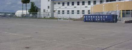
3 approach speeds. These higher minimums provide a larger margin of safety for these aircraft. TABLE 2-1 INSTRUMENT APPROACH PROCEDURES Procedure Name Minimum Visibility (Statute miles) Minimum Ceiling (AMSL) Precision Approaches ILS RWY 36R 1/2 mile 200 feet Nonprecision Approaches S-LOC 36R 1/2 mile 405 feet VOR RWY 9R 1 mile 562 feet GPS RWY 9R 1 mile 422 feet GPS RWY 18L 1 mile 420 feet GPS RWY 27L 1 mile 430 feet GPS RWY 36R 1/2 mile 445 feet ASR RWY 36R 1 mile 545 feet Notes: Ceiling is given in feet above the reported touchdown zone elevation. ASR = Airport Surveillance Radar; ILS = Instrument Landing System; RWY = Runway; S-LOC = Straightin Localizer; VOR = Very-high Frequency Omni-directional Range. Source: FAA, Southeast Terminal Procedures, September 2, In addition to the procedures listed above, circling approaches are also published based upon the above procedures. The approved minimums for circling approaches are generally, but not always, higher than those for straight-in approaches listed above. For example, the lowest minimums associated with the GPS RWY 36R procedure are a visibility of one mile and a ceiling of 459 feet. In recent years, the FAA has begun implementing Standard Terminal Arrival procedures, commonly referred to as STARs. Four procedures based upon STARs have been implemented at VQQ. These procedures give pilots directions to a selected navigational aid in the vicinity of the airport using predefined paths between instrument checkpoints. The FAA also regularly publishes these STARs procedures Runways The primary airfield components at an airport are the usable runways. At VQQ, four runways (9R-27L, 9L- 27R, 18R-36L, and 18L-36R) are currently operational. Each runway is briefly described below, including general information regarding pavement condition. Navigational aids (NAVIADs) associated with these runways are discussed in a subsequent report section. The runways and other airfield facilities are identified on Exhibit 2-2. The four runways were originally developed when the U.S. Navy operated the airport. As such, they were constructed to meet military standards, which differ somewhat from civilian standards set by the FAA. It appears that prior to JAA taking control of the airfield, the military performed limited maintenance on the facility. Because of this factor and the general age of the existing pavement, most of the runways were in various stages of deterioration and show various degrees of cracking when the transition occurred. Although previous maintenance appears limited, these pavements have had some rehabilitation work completed since the initial construction. Most of the airfield pavement shows some faded or partially removed military markings. Table 2-2 provides pavement materials used in the various pavement improvement projects since the initial construction of each runway. Exhibit 2-3 shows several photos taken during an onsite visit in September 2004 of the various areas of airfield pavement. The pavement construction materials are a major factor in determining the maximum weight aircraft that can utilize a runway on a regular basis without causing pavement deterioration or failure. This maximum aircraft weight is reported as the pavement bearing strength. This value differs based upon an aircraft s landing gear configuration. The pavement bearing strength generally increases as the number of wheels in the aircraft landing gear increases, due to the aircraft s landing weight being distributed over a greater pavement surface area. 2-3 DRAFT
4


5 Ponding on Taxiway A-1. Rubber buildup beginning to obscure runway centerline marking. Runway-36 exhibiting signs of grass growing in longitudinal cracks. Spalling on Runway 18L-36R. Recent overlay on Runway 18R-36L. Threshold lights at Runway 36R end. Photos taken on September 13, Example of HIRL along Runway 18L-36R. Airfield Pavement Photos Exhibit FINAL
6 TABLE 2-2 RUNWAY PAVEMENT HISTORY Runway Initial Construction Improvements x 200 4,500 x 200 (at each end) (Extension to 36R) (Overlay) 18L-36R Concrete: Concrete: 3 HMAC 10 PCC 11 PCC 1.5 HMAC 9 Limerock Base 6 Stabilized Subbase 4 Sand 6 Stabilized Base 10 Limerock Base 12 Compacted Subgrade x R-36L 9L-27R 9R-27L 3 HMAC 9 Limerock Base 6 Stabilized Subbase 4 Sand 3 HMAC 9 Limerock Base 6 Stabilized Subbase 4 Sand 2 HMAC 9 Limerock Base 9 Stabilized Subbase (at each end) Concrete: 10 PCC 6 Stabilized Base Note: HMAC = Hot-mix Asphalt Concrete; PCC = Portland Concrete Cement. Source: Reynolds, Hill & Smith, Cecil Field Strategic Airport Master Plan, (Overlay) 1.5 HMAC x 200 (at each end) (Overlay) (Overlay) Concrete: 10 PCC 1.5 HMAC 1.5 HMAC 6 Stabilized Base x 200 (at each end) (Overlay) (Overlay) Concrete: 10 PCC 1.5 HMAC 1.5 HMAC 10 Limerock Base 12 Compacted Subgrade --- Aircraft landing gear configurations can range from a single-wheel landing gear on the Cessna 172 to the Boeing 777 s twin-triple tandem wheel configuration having a total of 12 wheels in the main landing gear. The 1998 Master Plan, reported runway pavement bearing strengths, based on the noted landing gear configurations, for all runways at VQQ to be the following: Single wheel: 105,000 pounds Twin wheel: 165,000 pounds Single tandem wheel: 175,000 pounds Double tandem wheel: 315,000 pounds. These bearing strengths are based upon information from the 1998 Master Plan report, which referenced Volume 12 of the Low Altitude United States Department of Defense Flight Information Publication. As such, the gear configurations reflect traditional military terminology. In order to reflect more common civilian terminology, a current edition of the Airport/Facility Directory for the Southeast U.S. was consulted. This publication, which is produced by the FAA, provides examples of aircraft within each landing gear classification as well as gives some indication of equivalent configurations when considering pavement bearing strength. For example, the DC-6 is given as an example for both the twinwheel and dual-wheel categories. Based upon the information from the Facility Directory, it was determined that the pavement bearing strength for each runway could be estimated as: Single-wheel: 105,000 pounds Dual-wheel: 165,000 pounds Dual-tandem: 315,000 pounds. 2-6 DRAFT
7 Additionally, when JAA took over management of the facility the associated airfield lighting did not meet FAA standards and was in fair to poor condition throughout the airfield. The electrical cables were either direct buried or placed in asbestos cement duct banks along the pavement edges when originally installed. The older duct banks have over time absorbed water and many of the duct openings have shrunk. Design and construction projects were initiated in 2001 to upgrade the airfield electrical system to address these issues. This multiphase electrical upgrade project also included electrical vault upgrades and installation of a new beacon. This electrical upgrade project was completed in Runway 18L-36R The primary runway at VQQ is Runway 18L-36R, which has a length of 12,504 feet and a width of 200 feet. Runway 18L-36R was originally 8,000 feet with two 480-foot concrete sections at each runway end. As noted in the previous table, a 4,500-foot concrete extension was undertaken approximately seven years after the initial construction. The center section, having an approximate length of 7,040 feet, is of asphalt construction. Upon visual inspection, this pavement generally appears to be in good condition although some signs of pavement aging were apparent as shown in Figure 2-3. This runway is equipped with a high-intensity runway light (HIRL) system. The HIRLs emit white light, except in the last 2,000 feet of the runway where the lights are yellow to provide a visual indication to the pilot that they are approaching the runway end. These lights are located approximately five feet from the pavement edge. The edge lights are spaced no more than 200 feet apart. Lights are installed at the each end of this runway to mark the runway threshold. These bi-directional threshold lights appear red to pilots departing the runway and green to those approaching. No centerline lights or reflectors are installed. Runway 18L-36R has precision markings, which include aiming point, centerline, designation, side stripes, threshold, and touchdown zone markings. They are white in color, but some of the markings, primarily in the touchdown zone area, are currently obscured by rubber build-up Runway 18R-36L Runway 18R-36L is separated 700 feet from the primary runway, 18L-36R. This distance allows for simultaneous visual operations. The runway measures 8,003 feet by 200 feet. The pavement is constructed of sections of asphalt and concrete as previously detailed. Overall, the pavement appeared to be in good condition. During the onsite inventory, signs of cracking and of several patches were observed. The runway has nonprecision markings that are in fair condition. These include aiming point, centerline, designation, and threshold markings. Additionally, this runway has edge stripes as well as having touchdown zone markings located at the 18R end. This runway is equipped with a medium-intensity runway light system (MIRL), but this system is not operational due to mechanical problems with the aged circuitry Runway 9L-27R Runway 9L-27R is one of two runways oriented in a crosswind configuration at Cecil Field. It is separated from Runway 9R-27L by 700 feet. The runway pavement was constructed in a similar manner as other runways at VQQ, with the first 480 feet at each end being concrete and the remaining being asphalt. This runway has dimensions of 8,002 feet by 200 feet. Airport staff reports that the asphalt portion of this runway is in fair condition. It is not equipped with edge or centerline lights at this time. This runway has nonprecision markings that are generally in poor condition. In addition, side stripes have been added as well as touchdown markings at the Runway 27R end. Runway 9L-27R is not currently equipped with runway edge or centerline lights Runway 9R-27L This runway has similar characteristics to Runway 9L- 27R. It has dimensions of 8,003 feet x 200 feet and was constructed of a mix of asphalt and concrete pavement sections, as previously discussed. Upon visual inspection the pavement appeared to be in good condition with some localized areas showing signs of minor cracking. Runway 9R-27L currently is equipped with HIRL. Nonprecision markings have been applied to this runway. As with the other runways, edge stripes have been added. Touchdown zone markings are included for the Runway 9R end only Runway Safety Criteria The FAA has developed various safety standards to provide an adequate safety margin for aircraft operators and for others in the general vicinity of a runway. For runways, these standards vary based upon the aircraft wingspan and approach speed as well as the approved approach procedures to each 2-7 DRAFT
8 runway end. The following provides a brief description of the runway standards set by the FAA: Runway Safety Area (RSA): These areas are centered upon the runway centerline and run along the sides and ends of each runway. The RSA must be able to support maintenance and emergency response vehicles as well as the occasional passage of an aircraft. These areas must be smoothly graded and be free of any objects (except those needed to support aircraft operations) including aircraft and vehicles while an operation is occurring on the active runway. The RSA is intended to minimize damage to aircraft and injuries to passengers in the event an aircraft leaves the runway. Runway Object Free Area (OFA): This safety criteria provides a defined area, which runs along the sides of and beyond the runway end and must be free of any permanent objects. It is permissible to taxi and hold aircraft in an OFA, but not to park them in this area. Runway Protection Zones (RPZ): Airport operators should have legal control over the defined RPZ at each runway end. The RPZ is designed to protect developments and people on the ground. This area is statistically where most aircraft accidents are likely to occur. The shape of the area is a trapezoid with the shorter end located 200 feet beyond the runway end. The RPZs at opposite runway ends can have different dimensions based on the approved approach procedure to that runway end. Table 2-3 provides the dimensions of each of these standards at VQQ. These standards appear to be met for each of Cecil Field s four runways. RSA Length Beyond RW End TABLE 2-3 RUNWAY SAFETY CRITERIA OFA Length Beyond RW End Runway Width Width RPZ* 18L-36R 500 1, ,000 R/W 18L: 1,700 x 500 x 1,010 R/W 36R: 2,500 x 1,000 x 1,750 18R-36L 500 1, ,000 1,700 x 500 x 1,010 9L-36R 500 1, ,000 1,700 x 500 x 1,010 9R-36L 500 1, ,000 1,700 x 500 x 1,010 Note: *RPZ dimensions are given as length x inner width x outer width and are the same for both runway ends, unless otherwise noted. Source: FAA, AC 150/ , Airport Design; AVCON, INC., Analysis, Taxiways Aircraft utilize taxiways to maneuver on the ground between various airport facilities. At Cecil Field, taxiways not located along aircraft aprons were constructed in conjunction with the respective runways. All taxiways are equipped with blue edge lights and have yellow centerline markings. Additionally, the appropriate runway hold marking and signage mark each taxiway-runway intersection. It should be noted that at some locations, older markings have not been fully removed. The following sections provide a brief description of the existing taxiways Taxiway A This taxiway serves as a parallel taxiway to Runways 18R-36L and 18L-36R. Taxiway A has a centerline-tocenterline separation from Runway 18R-36L of 500 feet and of 1,200 feet from Runway 18L-36R. The asphalt pavement is 75 feet wide and has an approximate length of 12,500 feet. This taxiway crosses both runways oriented in the 9-27 direction Taxiway B Taxiway B serves as a full-length parallel taxiway to Runways 9R-27L and 9L-27R. The asphalt pavement is 75 feet wide and has a length of approximately 8,000 feet. This taxiway crosses both north-south runways Taxiway C This taxiway is 75 feet x 3,955 feet and is located along the southern edge of south apron. It extends from the westernmost apron edge and terminates at its intersection with Taxiway A. Taxiway C is constructed of concrete and has blue lights along its southern edge. The centerline for Taxiway B is located 250 feet from the Taxiway C centerline. 2-8 DRAFT


9 Taxiway D Taxiway D serves as a partial, parallel taxiway to the runways aligned at It is located on the eastern edge of the north apron. As such, it is of concrete construction and has lights along its east edge. It has a width of 75 feet and is approximately 5,750 feet in length. The centerline-to-centerline separation between Taxiway D and Taxiway A is 250 feet. in 2003 to address these issues. The cabling for the new signs was installed in conduit. It should be noted that in some areas, such as on the inboard Runways 9L-27R and 18R 36L, they were not connected to a power source since these facilities are for daytime operations only. Examples of airfield signage Other Taxiways Each parallel taxiway has a variety of right-angle taxiway connectors associated with them. These connector taxiways are 75 feet in width and have the appropriate centerline markings and blue edge lights. These connector taxiways are named with an alphanumerical system related to the full-length parallel taxiway they are associated with Airfield Signage The FAA has designated standard types of signs to be used on airfields. These signs provide a variety of information and can be classified into several functional categories. The airfield at VQQ has the following types of signs: Mandatory Instructional: These signs designate the entrance to a runway or instrument critical area as well as areas where no entry is allowed. They generally have white letters on a red background. Direction/Destination: These sign point the user to a certain airfield location, such as which direction a user should turn to reach the terminal. They also indicate the crossing taxiway at an intersection. These signs have black letters on a yellow background. Location: This classification of sign informs users of their current location, such as on which taxiway they are traveling. These signs have yellow letters on a black background. Informational: This group includes general informational signs, such as noise procedure reminders. These signs have a yellow background with black writing. Distance Remaining: This is a series of special informational signs that indicate how many thousands of feet of the runway are remaining for takeoff and landing operations Navigational Aids Airports are equipped with various navigational aids (NAVAIDS) to assist pilots as they operate to and from a facility. This equipment gives either visual or electronic cues to the pilot to assist them in navigation. This section describes the navigational equipment currently located at Cecil Field. Exhibit 2-2 illustrates the location of each NAVAID and Exhibit 2-4 provides photos of many of these facilities Airport Beacon The airport rotating beacon indicates the location of an airport at night or during inclement weather conditions by projecting beams of light spaced 180 degrees apart. The beacon rotates and projects alternating white and green beams, which identify a lighted civil airport. At Cecil Field, the beacon is located on top of the control tower. This beacon was recently installed and is in excellent condition. When JAA assumed managerial responsibility for the Airport, airfield signage met military standards, but not necessarily FAA standards. Additionally, the signage system was aged and was in need of significant upgrade. Signage was replaced throughout the airfield 2-9 FINAL


")


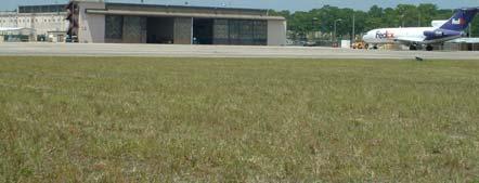
10 VOR PAPI box and windcone Glide Slope Antenna ASOS Localizer Rotating Beacon (on top of ATCT) Photos taken on September 13, Existing NAVAIDS Exhibit FINAL
11 Precision Approach Path Indicators The outboard runways, 9R-27L and 18L-36R, are equipped with Precision Approach Path Indicators (PAPIs) at each runway end. These units are considered visual approach aids, as pilots are able to determine if they are descending at an appropriate slope. The PAPIs at VQQ consist of four light boxes positioned on the runway s left side and in a row perpendicular to the runway. They are generally placed approximately 1,000 feet from the arrival threshold. The four lights are visible for a distance of 3 to 5 miles during the day and up to 20 miles at nighttime. The individual lights are positioned so as to give vertical guidance to clear all known obstacles plus an adequate safety margin on approach Approach Lights Two types of approach lights, which assist pilots in identifying the runway end, are currently installed at Cecil Field. Three runway ends (9R, 27L, and 18L) are equipped with Runway End Identifier Lights (REILS). These lights are placed on each side of the runway threshold. The REILS project an intense white strobe that can be seen by pilots on approach to the runway. These lights mark the arrival threshold on each runway. The second type of approach light system at VQQ is a Medium Intensity Approach Lighting System with Runway Alignment Lights (MALSR). This MALSR is installed in the grassy area leading up the approach end of Runway 36R. It is 1,400 feet in length and has multiple bars of lights that are approximately 200 feet apart, centered along the extended runway centerline. These lights supplement the precision instrument approach, discussed in Section Instrument Landing System Runway 36R is equipped with an Instrument Landing System (ILS) that supports a precision approach. The ILS consists of a localizer and a glide slope. The localizer is located beyond the Runway 18L pavement end and transmits a signal down the runway centerline towards the approach end of Runway 36R. The localizer provides pilots with horizontal guidance to the runway centerline. The localizer is also equipped with Distance Measuring Equipment (DME), which allows pilots in aircraft with DME instrumentation to calculate their distance from the airport. Additionally, the localizer can be used alone to support nonprecision approaches. The second component of the ILS is the glide slope, located to the right of Runway 36R approximately 1,050 feet from the arrival threshold. The glide slope provides vertical guidance information to a standard 3.0-degree approach path Very-high Frequency Omni-directional Range The Airport is also equipped with Very-high Frequency Omni-directional Range (VOR) equipment to support non-precision instrument approaches. It is located about 1,000 feet south of the Runway 9R threshold. The VOR transmits radio signals in a circular array, which are used by the pilot to determine the course being flown Weather Systems Weather conditions, especially wind direction and speed, are important to aircraft operations. Two types of equipment monitor on-airport weather conditions at the Airport. The first is an Automated Surface Observing System (ASOS), which generally monitors various weather conditions such as wind, precipitation, temperature, and surface visibility. The ASOS at Cecil Field is located approximately 1,700 feet southeast of the intersection of Runways 9R-27L and 18L-36R. The other weather monitoring equipment at the Airport are multiple lighted wind cones, such as the one shown in Exhibit Aircraft Aprons Currently, Cecil Field has two aprons that can be utilized by either tenants or transient users. The largest apron at the Airport is oriented in a north-south direction, beginning at Taxiway C and ending at the northern edge of Taxiway D. This apron has multiple hangars along its west side, which are all currently leased or are being upgraded for incoming tenants. The major section of this apron, which is of concrete construction, measures approximately 5,450 feet x 615 feet. Overall this apron has almost 385,700 square yards of pavement DRAFT


12 standards. These improvements were necessary before the Aviation Authority could lease them. Exhibit 2-5 identifies many of these landside and support facilities. Pavement patch on apron. The pavement appeared to be in good condition upon visual inspection, showing very little cracking, spalling, or vertical shifting of the individual concrete pads. Several small areas have been repaired, mostly at the junction of several slabs. Throughout the apron are metal plates that cover the military s former underground fueling stations. The fueling system has been decommissioned, but most of the metal covers remain. This apron has metal tiedown brackets located throughout it for aircraft parking. The second apron area is located along the flight line for the east-west runways. This apron has approximately 185,000 square yards of pavement. Like the northern apron, it is constructed of concrete and appeared to be in good condition. The western portion of the ramp is utilized solely by the National Guard unit based at the Airport Service Roads The airfield is encircled by a perimeter road, which is paved with asphalt. It is in fair to good condition. Additionally, multiple roads that connect old military bunkers are located in the western portion of the airport property. These roads also provide easy access to the maintenance buildings and various NAVAIDs, such as the ASOS and VOR. 2.2 LANDSIDE AND SUPPORT FACILITIES This section describes the landside and support facilities at Cecil Field, including tenant buildings, the fuel farm, and the control tower. Some of these facilities were in poor condition when control of the Airport was transferred to JAA. Many of the oldest structures had lead paint and asbestos and were in need of roof repairs. Additionally, some facilities required upgrades to meet current federal, state, and local regulations related to handicapped accessibility and other building codes, including electrical Tenants JAA leases most of the current structures located along the two flightlines to various companies and government organizations. Photos of many of the tenant facilities are shown in Exhibit 2-6. Many tenants also lease the smaller buildings located near their primary facility. Tenant locations and activities are briefly described below: Airborne Tactical Advantage Company (ATAC): ATAC provides a growing fleet of tactical aircraft and services to the US military, including outsourced airborne tactical training, threat simulation, and research & development. ATAC sub-leases the southern quarter of Hangar 825 from Boeing. Air One: Air One is a full service FBO. Currently, they do not conduct maintenance activities but are planning on offering this service once their new hangar is built. Air One currently leases building 47 and has constructed a 90,000 gallon fuel farm. Boeing Company: In 1999, Boeing opened its Aerospace Support Center Cecil at the Airport. Currently, Boeing leases four hangars (67, 825, 1820, and 1845) out of which they have performed maintenance and modifications to F-18 Hornet, KC-10, C-17, and T-45 aircraft. These three hangars have a total area of approximately 270,000 square feet (SF). Boeing also leases some ramp space located in front of these hangars. Flightstar: In 2004, Hangar 815 underwent expansion modifications to provide additional floor space and to accommodate tail sections of aircraft. Flightstar currently leases this hangar where they provide maintenance, overhaul, and repair services. The company has performed these services on B727, B737, DC9, and MD80 aircraft. Florida Air National Guard: A helicopter unit of the state s National Guard is based at the Airport. This unit currently stores multiple Apache helicopters in their leased Hangar 860, with 84,000 sf. In the near future, this unit will switch to operating Chinook helicopters. Building 858 is used for training rooms and offices FINAL
13

")
")
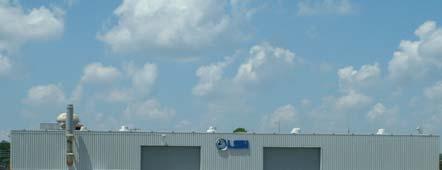


14 Florida Army National Guard (#4) Boeing (#1820) LSI (#824) Terminal/ATCT/Administration (#82) FL Air National Guard (#860) U.S. Customs/FL Community College (#14) Photos taken in August and September Tenant Photos Exhibit FINAL
15 Florida Community College at Jacksonville, Aviation Center of Excellence: This local community college operates a satellite center dedicated to the aviation sector. Students can focus on aviation management or aircraft maintenance as well as flight training. The College leases Hangar 14, which is in poor condition, from JAA. The airport authority has a project programmed for 2004 to rehabilitate this hangar. The College also has additional classrooms in a building located along Lake Fretwell Street. Jet Turbine Services, Inc.: This firm provides support services for Boeing operations, specifically on aircraft jet engines. Jet Turbine Services operates from Building 313. This 56,100 square foot facility does not have direct access to the apron. Logistics Services International (LSI): This firm provides maintenance, repair, and overhaul services from Hangar 824. Additionally, LSI provides training services to the aerospace and security industries from a facility in the Cecil Commerce Center. Fleet Readiness Center, Southeast (FRC SE): FRC SE, previously known as NADEP, provides F-18 modifications for the US Navy. They operate a satellite hangar, Hangar 1845, at Cecil Field with the main hangar at NAS Jacksonville. Robinson VanVuren & Associates (RVA): This firm is responsible for providing air traffic control services as part of the FAA s Contract Tower Program. This facility is considered a Level 1 Tower, which includes airports with low activity levels. RVA operates from the air traffic control tower (ATCT) that is located within the terminal building (#82). The ATCT is operational daily from 7 a.m. to 9 p.m. Signature Flight Support: This company serves as the Fixed-Base Operator (FBO) at the Airport. This FBO provides aviation fuel, aircraft parking, hangars, oxygen service, pilot services, and limited catering. Signature moved into the completed terminal in October They also utilize the hush house (#818) for storage of aircraft and other materials. Titan System Corporation: Titan offers communication and informational system services with a focus on national defense issues. This firm operates from Building 887. United States Customs Agency: This federal agency shares Hangar 14 with the Florida Community College. They typically house six P-3 Orion aircraft in this facility. United States Coast Guard: This military unit operates a fleet of Agusta helicopters from Hangar 13. They are also currently rehabilitating Hangar 1846 to be used for maintenance Support Facilities Most airports have several facilities dedicated to support activities. At Cecil Field, these support capabilities include airport administration, an electrical vault, emergency response units, a control tower, and fuel farm. These facilities are identified in Exhibit 2-5 and are described in the following subsections Aircraft Rescue and Firefighting Facility Building 22 houses an onsite Aircraft Rescue and Firefighting (ARFF) unit. This facility is a joint-use operation with the City of Jacksonville. Firefighters stationed at this facility are trained to respond to aircraft incidents. The unit has three ARFF vehicles as well as more traditional structural units. These vehicles are stored in the four vehicle bays in the building. The structure is of concrete block construction and has approximately 8,000 square feet of space Air Traffic Control Tower As noted in Section 2.2.1, Cecil Field has an onsite air traffic control tower (ATCT). This facility is located near the intersection of the inboard runways in Building 82 as shown on Exhibit 2-5. Some upgrades are needed to this five-story facility Electrical Vault Building 83 serves as the airfield electrical vault. It houses multiple regulators for the various lighting, signage, and NAVAID equipment located on the airfield. It also houses a generator to provide power to these circuits for a limited time as needed. Equipment in the vault has been and will continue to be upgraded in conjunction with airfield electrical upgrade projects Fuel Farm Two fuel farms currently serve Cecil Field. The first fuel farm, operated by Signature, is located north of the terminal building. Currently, three aboveground storage tanks (ASTs) are located at this site. Two tanks have capacities of 12,000-gallon whereas the capacity of the third tank is 20,000 gallons. All three 2-15 FINAL


16 intersection at Interstate 10, scheduled to be open Fall Brannan Field Chaffee Road will initially be constructed as a two-lane limited access road with right of way and planning for two additional lanes with overpasses at the major intersections. This improvement will significantly increase ground access for Cecil Field. Fuel farm tanks store Jet A fuel. Signature operates several trucks to deliver fuel to users. Air One FBO also has a second fuel farm. Additionally, the Aviation Authority also has a small self-serve fuel area for unleaded and diesel fuel. These are used by airport staff to fuel airport service vehicles. This fueling area is located north of the aviation fuel farm within the airfield perimeter fence Airport Administration JAA has a staff dedicated to managing Cecil Field. This staff includes an airport manager, administrative support staff, operations personnel, and facility maintenance. Since the completion of the terminal renovations in October 2004, staff has moved into their permanent location in Building Primary Access Roads Exhibit 2-7 identifies major roadways near Cecil Field. Users access the Airport by traveling through Cecil Field Commerce Center, which has two entrances off of 103rd Street. This road is also designated as County Road 29 and provides a direct connection to I- 295 and the downtown area. Located just north of 103rd Street is Normandy Boulevard, which is also known as State Road 228. This road runs along the northwest corner of the Commerce Center and provides access to and from Interstate 295, which is approximately seven miles from the Airport area. Chaffee Road currently provides the most direct connection to Interstate 10. Interstates 10 and 95 can easily be accessed from the Interstate 295 loop. Additionally, Interstate 10 provides a connection to Interstate 75, which is located approximately 66 miles west of Jacksonville. Other roads near the Airport are Bell Road located to the west and Brannan Field- Chaffee Road on its eastern border. The short-term transportation improvement plan for the Jacksonville area shows improvements slated to widen Brannan Field-Chaffee Road and to construct a new Perimeter Fencing A six-foot high chain-link fence encompasses the majority of the airport boundary. Additionally, a fence is located along the east side of the airfield inside of the outer perimeter fence. This interior fence functions to segregate the Air Operations Area (AOA). Vehicular and pedestrian gates are spaced periodically to allow the passage of individuals who have been granted the authority to enter these areas Utility Infrastructure The multiple buildings at Cecil Field require traditional utility services, including the provision of water, sewer, power and natural gas services. Additionally, stormwater management conveyance systems have to be adequately sized to handle runoff from precipitation events. This section briefly describes the existing utility infrastructure at the Airport. It should be noted that this infrastructure is concentrated along the developed flightline areas, with only limited services in the eastern section of the airport property Water, Sewer, and Power Since the Navy turned over management of the property to the Aviation Authority, the Jacksonville Electric Authority (JEA) has assumed control of the water, sewer, and power utilities on airport property and within Cecil Commerce Center. JEA operates an onsite water and sewer treatment plant in the Commerce Center. Directly tied to the provision of water services, is the ability to provide adequate fire protection in aircraft hangars. In some existing facilities, fire protection capability is somewhat limited. Since taking control of VQQ, the Aviation Authority has undertaken a multiphase project to improve the existing fire loop, which provides water to the various hangar fire suppression systems. The final phase of this project was completed in Natural Gas TECO Gas provides natural gas service to facilities at the Airport. The main service lines run along airport s border with the Commerce Center. JAA utilizes natural gas to power some boiler systems FINAL

17
18 Stormwater Facilities Runoff from airport areas is routed and contained in multiple stormwater management facilities. These facilities include a series of inlets and outfalls connected via underground pipes and ditches. In the recent past, some drainage failures have been observed under airfield pavement; however, none were observed during the site visit. The advanced aging is not totally unexpected as many of these facilities were installed over 60 years ago. Further information is provided in the Environmental Overview section of this report. 2.3 SUMMARY This inventory discussion provides a snapshot of the existing conditions at VQQ through September 2004 with a limited update to It is not intended that this information represent an exhaustive listing of every detail of the Airport; however, it does provide the basic information for subsequent steps in this master planning process. Facilities identified as being in fair or poor condition will be considered for future improvements or replacement during the Facility Requirements analysis FINAL
Source: Chippewa Valley Regional Airport ASOS, Period of Record
 Chapter 1 Inventory Runway wind coverage is the percentage of time a runway can be used without exceeding allowable crosswind velocities. Allowable crosswind velocities vary depending on aircraft size
1.1.3 Taxiways. Figure 1-15: Taxiway Data. DRAFT Inventory TYPICAL PAVEMENT CROSS-SECTION LIGHTING TYPE LENGTH (FEET) WIDTH (FEET) LIGHTING CONDITION
 WIDTH (FEET) LIGHTING CONDITION") 1.1.3 Taxiways EWN has an extensive network of taxiways and taxilanes connecting the terminal, air cargo, and general aviation areas with the runways as listed in Figure 1-15. A 50-foot wide parallel taxiway
1.1.3 Taxiways EWN has an extensive network of taxiways and taxilanes connecting the terminal, air cargo, and general aviation areas with the runways as listed in Figure 1-15. A 50-foot wide parallel taxiway
BELFAST MUNICIPAL AIRPORT OVERVIEW
 BELFAST MUNICIPAL AIRPORT OVERVIEW LOCATION AND HISTORY Belfast Municipal Airport (Federal Aviation Administration (FAA) airport code BST, International Civil Aviation Organization airport code KBST, FAA
DRAFT MASTER PLAN UPDATE
 DRAFT MASTER PLAN UPDATE CHAPTER VI: AIRPORT LAYOUT PLAN NARRATIVE DRAFT REPORT APRIL 2017 PREPARED BY: Table of Contents WESTCHESTER COUNTY AIRPORT 6 AIRPORT LAYOUT PLAN NARRATIVE REPORT... 6-1 6.1 AGIS
CHAPTER 1 INTRODUCTION AND BACKGROUND
 CHAPTER 1 INTRODUCTION AND BACKGROUND An Environmental Assessment (EA) evaluates the effects of a proposed Federal action on the surrounding environment and is prepared in compliance with the National
Table of Contents. Overview Objectives Key Issues Process...1-3
 Table of Contents Chapter One Introduction Overview...1-1 Objectives...1-1 Key Issues...1-2 Process...1-3 Chapter Two Inventory of Existing Conditions Airport Setting...2-1 Locale...2-1 Airport Surroundings...2-5
Milton. PeterPrinceAirportislocatedinSantaRosaCounty, approximatelythreemileseastofmilton.
 Milton GeneralAviationAirport PeterPrinceAirportislocatedinSantaRosaCounty, approximatelythreemileseastofmilton. Existing Facilities Peter Prince Airport is served by one runway, Runway 18/36, 3,700 feet
Runway and Taxiway Marking
 Lecture-38 10CV63 TE-II Runway and Taxiway Marking In order to aid pilots in guiding the aircraft on runways and taxiways, pavements are marked with lines and numbers. These markings are of benefit primarily
FACILITY REQUIREMENTS SUMMARY OF KEY ISSUES OVERVIEW
 FACILITY REQUIREMENTS SUMMARY OF KEY ISSUES OVERVIEW This summary is intended to provide a brief overview of the key issues associated with conformance to FAA standards at Methow Valley State Airport.
CATCODE ] CATCODE
![CATCODE ] CATCODE](/thumbs/82/85644630.jpg "CATCODE ] CATCODE") Runways. FAC: 1111 CATCODE: 111111 OPR: AFCEC/COS OCR: AF/A3O-A 1.1. Description. The runway is the paved surface provided for normal aircraft landings and take offs. Runways are classified as either Class
Runways. FAC: 1111 CATCODE: 111111 OPR: AFCEC/COS OCR: AF/A3O-A 1.1. Description. The runway is the paved surface provided for normal aircraft landings and take offs. Runways are classified as either Class
Chapter 9 - AIRPORT SYSTEM DESIGN
 Chapter 9 - AIRPORT SYSTEM DESIGN 9.01 GENERAL This chapter discusses the development program for Dutchess County Airport to the year 2020. This airport system design is based upon the airport's existing
CHAPTER 5 - FACILITY REQUIREMENTS
 CHAPTER 5 - FACILITY REQUIREMENTS This chapter identifies the requirements for airfield and landside facilities to accommodate the forecast demand level. Facility requirements have been developed for the
Hartford-Brainard Airport Potential Runway Closure White Paper
 Hartford-Brainard Airport Potential Runway 11-29 Closure White Paper June 2012 In recent years there has been discussion regarding the necessity of Runway 11-29 to the Hartford- Brainard Airport (HFD)
Addendum - Airport Development Alternatives (Chapter 6)
") Bowers Field Addendum - Airport Development Alternatives (Chapter 6) This addendum to the Airport Development Alternatives chapter includes the preferred airside development alternative and the preliminary
Bowers Field Addendum - Airport Development Alternatives (Chapter 6) This addendum to the Airport Development Alternatives chapter includes the preferred airside development alternative and the preliminary
Tallahassee International Airport Master Plan. Technical Advisory Committee Meeting #2 October 19, 2016
 Tallahassee International Airport Master Plan Technical Advisory Committee Meeting #2 October 19, 2016 Agenda Welcome / Introductions Master Plan Process and Project Status Forecast of Aviation Demand
Chapter Three AIRPORT FACILITY REQUIREMENTS/ALTERNATIVES
 Chapter Three AIRPORT FACILITY REQUIREMENTS/ALTERNATIVES Airport Layout Plan Report In this chapter, existing components of the Airport are evaluated so that the capacities of the overall system are identified.
Navigation - Runways. Chap 2, Nolan
 Navigation - Runways Chap 2, Nolan 1 Runways Runways numbered to correspond to magnetic bearing Runway 27 has magnetic bearing 270 degrees Active Runway selected for headwind greater than 5 knots When
EXECUTIVE SUMMARY INTRODUCTION EXISTING CONDITIONS CECIL FIELD MASTER PLAN UPDATE
 ES-1 INTRODUCTION Cecil Field opened as a military airfield to train and serve as a home base for U.S. Navy and Army aviators during World War II. It continued in a military role until 1999 when it was
STUDY WORK GROUP MEETING No. 3. November 29, 2016
 STUDY WORK GROUP MEETING No. 3 November 29, 2016 Agenda Welcome and introductions Update project schedule Brief overview of previous SWG meeting Update on aviation forecasts Introduction to airfield demand/capacity
Airport Master Plan. Brookings Regional Airport. Runway Runway 17-35
 Runway 17-35 Airport Master Plan Runway 12-30 Brookings Regional Airport Table of Contents Table of Contents Chapter 1: Master Plan Goals... 1-1 1.1. Introduction... 1 1.2. Objective 1 Identify improvements
50 Ways to Improve Your Airport: Engaging Airport Management on Key Issues
 50 Ways to Improve Your Airport: Engaging Airport Management on Key Issues Tuesday, November 17, 2015 1:00 p.m. 2:00 p.m. PRESENTED BY: Charles D. Lamb, P.E. Airfield Lighting Image Source: Delta Airport
Document prepared by MnDOT Office of Aeronautics and HNTB Corporation. MINNESOTA GO STATE AVIATION SYSTEM PLAN
 LAST UPDATE JULY 2013 Acknowledgements The preparation of this document was financed in part by a grant from the Federal Aviation Administration (Project No: 3-27-0000-07-10), with the financial support
Chippewa-Eau Claire Metropolitan Planning Area Long Range Transportation Plan
 1.2.7 2010 Eau Claire County Comprehensive Plan According to Eau Claire County s most recent comprehensive plan, the County will limit land use development adjacent to EAU in order to preserve the ability
APPENDIX C AIRSPACE PROCEDURES
 APPENDIX C AIRSPACE PROCEDURES This appendix is designed to provide the reader with an introduction to how aircraft operate in and around Cincinnati/Northern Kentucky International Airport (CVG), the facilities
Chapter The All-new, World-class Denver International Airport Identify Describe Know Describe Describe
 Chapter 10 The aerospace subject is very large and diverse. As seen in previous chapters, there are many subject areas. So far you have learned about history, weather, space and aerodynamics. Now you will
AIRSIDE CAPACITY AND FACILITY REQUIREMENTS
 AIRSIDE CAPACITY AND FACILITY REQUIREMENTS This Section investigates the capacity of the airport, its ability to meet current demand, and the facilities required to meet forecasted needs as established
Preliminary Findings of Proposed Alternative
 Preliminary Findings of Proposed Alternative The attached drawing provides a schematic layout of the proposed alternative that will be discussed on July 27, 2010. A full report will follow and should be
CHAPTER 1 BACKGROUND AND PROPOSED ACTION
 CHAPTER 1 BACKGROUND AND PROPOSED ACTION 1.0 INTRODUCTION An Environmental Assessment (EA) evaluates the effects of a proposed Federal action on the surrounding environment and is prepared in compliance
Inventory of Existing Conditions.
 A Inventory of Existing Conditions. Fort Collins-Loveland Municipal Airport, jointly owned and operated by the Cities of Fort Collins and Loveland, is located in the heart of a region with a thriving economy,
CHAPTER 3 ALTERNATIVES CONSIDERED
 CHAPTER 3 ALTERNATIVES CONSIDERED 3.0 ALTERNATIVES The 2010 Stevensville Airport Master Plan contained five (5) airside development options designed to meet projected demands. Each of the options from
Merritt Island Airport
 TABLE OF CONTENTS CHAPTER 1 INTRODUCTION... 1-1 INTRODUCTION AND PROJECT OVERVIEW... 1-1 General Guidelines... 1-1 Prior Planning Documentation... 1-2 Key Issues... 1-2 Goals and Objectives... 1-2 Regulatory
Agenda: SASP SAC Meeting 3
 Agenda: SASP SAC Meeting 3 Date: 04/12/18 Public Involvement Plan Update Defining the System Recommended Classifications Discussion Break Review current system Outreach what we heard Proposed changes Classification
1 DRAFT. General Aviation Terminal Services Aircraft Hangars Aircraft Parking Aprons Airport Support Facilities
 To properly plan for improvements at Dallas Executive Airport, it is necessary to translate forecast aviation demand into the specific types and quantities of facilities that can adequately serve the demand.
OVERVIEW BASIC DESIGN FACTORS. Demand Determinants
 3 Airfield Airfield Design Design OVERVIEW The basic configuration of the runway and taxiway system at Hanford Municipal Airport has changed moderately since the airport was constructed in 1950. These
ICAO Standards. Airfield Information Signs. ICAO Annex 14, 4th Edition Aerodrome Design and Operations
 ICAO Standards Airfield Information Signs ICAO Annex 14, 4th Edition Aerodrome Design and Operations Federal Aviation Administration U.S. Department of Transportation February 2004 ICAO Standards This
 IFR 91.157 Must be instrument rated to fly special VFR at Night (civil twilight to civil twilight, sun 6 degrees below horizon) 91.159 Unless in a holding pattern of 2 minutes or less, VFR cruising altitude
The purpose of this Demand/Capacity. The airfield configuration for SPG. Methods for determining airport AIRPORT DEMAND CAPACITY. Runway Configuration
 Chapter 4 Page 65 AIRPORT DEMAND CAPACITY The purpose of this Demand/Capacity Analysis is to examine the capability of the Albert Whitted Airport (SPG) to meet the needs of its users. In doing so, this
Executive Summary. MASTER PLAN UPDATE Fort Collins-Loveland Municipal Airport
 Executive Summary MASTER PLAN UPDATE Fort Collins-Loveland Municipal Airport As a general aviation and commercial service airport, Fort Collins- Loveland Municipal Airport serves as an important niche
TECHNICAL REPORT #3 Palm Beach International Airport Demand/Capacity and Facility Requirements
 TECHNICAL REPORT #3 Palm Beach International Airport Demand/Capacity and Facility Requirements Technical Report #3 Palm Beach International Airport Demand/Capacity and Facility Requirements Palm Beach
Appendix C AIRPORT LAYOUT PLANS
 Appendix C AIRPORT LAYOUT PLANS Appendix C AIRPORT LAYOUT PLANS Airport Master Plan Santa Barbara Airport As part of this Airport Master Plan, the Federal Aviation Administration (FAA) requires the development
ArcadiaMunicipalAirportislocatedonthesoutheast sideofarcadia,southofstateroute70,westofstate Route31,andisaccessiblefrom AirportRoad.
 Arcadia GeneralAviationAirport ArcadiaMunicipalAirportislocatedonthesoutheast sideofarcadia,southofstateroute70,westofstate Route31,andisaccessiblefrom AirportRoad.Arcadia islocatedapproximately30milesnortheastoftheport
3 INTRODUCTION. Chapter Three Facility Requirements. Facility Requirements PEAKING CHARACTERISTICS
 Chapter Three Facility Requirements 3 INTRODUCTION This chapter identifies the long-range airfield and terminal area facilities needed to satisfy the 20-year forecast of aviation demand at Monett Municipal
Vista Field Airport. Master Plan Update. February, Prepared for: Port of Kennewick One Clover Island Kennewick, Washington
 Vista Field Airport February, 2006 Prepared for: Port of Kennewick One Clover Island Kennewick, Washington 99336 Prepared by: J-U-B ENGINEERS, Inc. 2810 W. Clearwater Avenue, Suite 201 Kennewick, Washington
Current and Forecast Demand
 Existing Facilities Jacksonville International Airport (JIA) is served by a number of airside and landside facilities. There are two runways that serve the airport in an open V configuration. The Annual
6.1 INTRODUCTION 6.2 AIRSIDE ALTERNATIVES NORTH PERRY AIRPORT MASTER PLAN UPDATE RUNWAY LENGTH REQUIREMENTS SECTION 6: ALTERNATIVES ANALYSIS
 6.1 INTRODUCTION In the previous chapter, facility needs for the 20-year planning horizon were identified. The next step in the planning process is to identify and evaluate the various ways certain facilities
CHAPTER 3 FACILITY REQUIREMENTS
 CHAPTER 3 FACILITY REQUIREMENTS 3.1 INTRODUCTION To properly plan for the future requirements of Newport News/Williamsburg International Airport, it is necessary to translate the forecasts of aviation
CHAPTER 3 AIRPORT FACILITY REQUIREMENTS
 CHAPTER 3 AIRPORT FACILITY REQUIREMENTS 3.1 Introduction The existing runway and taxiway system at Skyhaven Airport provides more than adequate operational capacity to accommodate future peak hour and
TECHNICAL REPORT #7 Palm Beach International Airport Airport Layout Plan
 TECHNICAL REPORT #7 Palm Beach International Airport Airport Layout Plan Technical Report #7 Palm Beach International Airport Layout Plan Palm Beach International Airport Prepared for Palm Beach County
AERONAUTICAL SURVEYS & INSTRUMENT FLIGHT PROCEDURES
 AERONAUTICAL SURVEYS & INSTRUMENT FLIGHT PROCEDURES Current as of November 2012 ALASKA AVIATION SYSTEM PLAN UPDATE Prepared for: State of Alaska Department of Transportation & Public Facilities Division
Appendix B Ultimate Airport Capacity and Delay Simulation Modeling Analysis
 Appendix B ULTIMATE AIRPORT CAPACITY & DELAY SIMULATION MODELING ANALYSIS B TABLE OF CONTENTS EXHIBITS TABLES B.1 Introduction... 1 B.2 Simulation Modeling Assumption and Methodology... 4 B.2.1 Runway
Chapter 4 Airport Facility Requirements
 Chapter 4 Airport Facility Requirements Introduction CHAPTER 4 AIRPORT FACILITY REQUIREMENTS MAY 2013-1 Organization of Materials CHAPTER 4 AIRPORT FACILITY REQUIREMENTS MAY 2013-2 RPZ - ROAD RPZ - NON-AIRPORT
CHAPTER 1 EXECUTIVE SUMMARY
 CHAPTER 1 EXECUTIVE SUMMARY 1 1 EXECUTIVE SUMMARY INTRODUCTION William R. Fairchild International Airport (CLM) is located approximately three miles west of the city of Port Angeles, Washington. The airport
MASTER PLAN CONCEPT 1 DRAFT
 The Airport Master Plan Update for Dallas Executive Airport has included the development of aviation demand forecasts, an assessment of future facility needs, and the evaluation of airport development
1.0 Project Background Mission Statement and Goals Objectives of this Sustainable Master Plan
 TABLE OF CONTENTS CHAPTER 1 INTRODUCTION 10 Project Background 1-1 11 Mission Statement and Goals 1-1 12 Objectives of this Sustainable Master Plan 1-2 CHAPTER 2 INVENTORY 20 Airport Background 2-1 201
DRAFT FINAL REPORT AIRPORT MASTER PLAN. Rifle Garfield County Airport Revised May 15, 2014
 DRAFT FINAL REPORT AIRPORT MASTER PLAN Rifle Garfield County Airport Revised May 15, 2014 As required by Paragraph 425.B(4) of FAA Order 5100.38C, Airport Improvement Program (AIP) Handbook: The preparation
RULES OF TENNESSEE DEPARTMENT OF TRANSPORTATION AERONAUTICS DIVISION CHAPTER LICENSING AND REGISTRATION OF AIRPORTS TABLE OF CONTENTS
 RULES OF TENNESSEE DEPARTMENT OF TRANSPORTATION AERONAUTICS DIVISION CHAPTER 1680-1-2 LICENSING AND REGISTRATION OF AIRPORTS TABLE OF CONTENTS 1680-1-2-.01 Purpose 1680-1-2-.06 Repealed 1680-1-2-.02 Definitions
SITE ELEVATION AMSL...Ground Elevation in feet AMSL STRUCTURE HEIGHT...Height Above Ground Level OVERALL HEIGHT AMSL...Total Overall Height AMSL
 ******************************************** * Federal Airways & Airspace * * Summary Report * ******************************************** File: User Assigned File Name Latitude: NAD83 Coordinate Longitude:
Safety, Infrastructure, and Tenant Improvement Project. Public Hearing Informational Brochure February 26, 2013
 New York State Department of Transportation Safety, Infrastructure, and Tenant Improvement Project Public Hearing Informational Brochure February 26, 2013 This DEIS/Draft EA evaluates the potential impacts
a. Aeronautical charts DID THIS IN LESSON 2
 AIRMAN CERTIFICATION STANDARDS: REMOTE PILOT SMALL: You will know and be able to explain in writing or oral form the below tasks regarding AIRPORT OPERATIONS Task References Objective Task B. Airport Operations
Chapter 2: Existing Facilities
 Chapter 2: Existing Facilities This chapter describes the existing conditions at the airport and provides an inventory of existing facilities and infrastructure. It provides the baseline for future requirements,
Draft Concept Alternatives Analysis for the Inaugural Airport Program September 2005
 Section 10 Preferred Inaugural Airport Concept 10.0 Introduction The Preferred Inaugural Airport Concept for SSA was developed by adding the preferred support/ancillary facilities selected in Section 9
The Future of Aviation for Central New Mexico
 The Future of Aviation for Central New Mexico MISSION STATEMENT THE WHOLE AIRPORT EXPERIENCE HISTORY SPECIFICATIONS FACILITIES SERVICES RECENT IMPROVEMENTS FUTURE DEVELOPMENT & USE USER PROFILE The mission
chapter 5 Recommended Master Plan Concept airport master plan MASTER PLAN CONCEPT
 chapter 5 Recommended Master Plan Concept airport master plan The planning process for Coolidge Municipal Airport has included several analytical efforts in the previous chapters intended to project potential
Grants Pass Airport Master Plan & Airport Layout Plan Update
 Attendees: Grants Pass Airport Master Plan & Airport Layout Plan Update Meeting #3 January 26, 2010 Merlin Community Center 100 Acorn Street, Merlin 5:45 7:15 p.m. Josephine County Department of Airports:
Acronyms. Airport Layout Plan Report Appendix A A-1
 Appendix A Acronyms AC... Advisory Circular ADG... Airplane Design Group ADO... Airport District Office AGL... Above Ground Level AIM... Aeronautical Information Manual AIP... Airport Improvement Program
MetroAir Virtual Airlines
 MetroAir Virtual Airlines NAVIGATION BASICS V 1.0 NOT FOR REAL WORLD AVIATION GETTING STARTED 2 P a g e Having a good understanding of navigation is critical when you fly online the VATSIM network. ATC
The following criteria shall be applied within the boundaries of the AO District:
 Sec. 419 (a) Purpose AIRPORT OVERLAY DISTRICT (AO) The purpose of the Airport Overlay District is to regulate and restrict the height of structures, objects, or natural growth, regulate the locations of
TABLE OF CONTENTS. General Study Objectives Public Involvement Issues to Be Resolved
 TABLE OF CONTENTS Description Page Number LIST OF ACRONYMS... a CHAPTER ONE INTRODUCTION General... 1-1 Study Objectives... 1-1 Public Involvement... 1-2 Issues to Be Resolved... 1-2 CHAPTER TWO EXISTING
1 PURPOSE AND NEED 1.1 INTRODUCTION
 1.1 INTRODUCTION 1 PURPOSE AND NEED This Environmental Assessment (EA) addresses projects at Juneau International Airport (JIA) that are the direct outcome of a Master Plan prepared for the airport and
R FAA
 Chapter Four Section 01 - Introduction Section 02 - Criteria for Determination of Facility Requirement Recommendations Section 03 - FAA Design Standards & Non-Standard Conditions Section 04 - Airfield
Chapter One INVENTORY
 Chapter One INVENTORY Airport Layout Plan Report The initial step in the preparation of the Airport Layout Plan Report for is the collection of information pertaining to the Airport and the area it serves.
15 Precision Approach Path Indicator 33 None RSA 150 feet wide by 300 feet long 150 feet wide by 300 feet long
 The first (AMP) was completed in 1984 and updated in 2000. The current FAA approved Airport Layout Plan (ALP) is dated November 9, 2001. The FAA suggests updating the AMP every five year in accordance
Chapter 4 Facility Requirements
 Chapter 4 Facility Requirements Introduction This chapter evaluates the existing airport facilities and identifies improvements needed to effectively meet the forecasted demand levels discussed in the
SURFACE MOVEMENT GUIDANCE AND CONTROL SYSTEM PLAN. Los Angeles International Airport
 SURFACE MOVEMENT GUIDANCE AND CONTROL SYSTEM PLAN Los Angeles International Airport Surface Movement Guidance and Control System (SMGCS) Plan The SMGCS Plan for Los Angeles International Airport (LAX)
OLD AIRPORT (PFN) RW 05/23 RW 14/32. 4,884-FEET X 150-FEET MIRL 4-BOX VASIs (5 & 23 APPROACHES) REILS
 RW 05/23 RW 14/32. 4,884-FEET X 150-FEET MIRL 4-BOX VASIs (5 & 23 APPROACHES) REILS") FAITH ADAMS AGENDA AIRPORT RELOCATION CHALLENGES AIRFIELD LIGHTING & SIGNAGE NAVAIDS AIRFIELD LIGHTING VAULT L-890 ALCMS AIR TRAFFIC CONTROL TOWER (ATCT) CONCLUSION AIRPORT RELOCATION OLD AIRPORT (PFN)
FAITH ADAMS AGENDA AIRPORT RELOCATION CHALLENGES AIRFIELD LIGHTING & SIGNAGE NAVAIDS AIRFIELD LIGHTING VAULT L-890 ALCMS AIR TRAFFIC CONTROL TOWER (ATCT) CONCLUSION AIRPORT RELOCATION OLD AIRPORT (PFN)
DEPARTMENT: CIVIL ENGINEERING SEMESTER: III SUBJECT CODE / Name: CE2303/ Railway, Airport and Harbors Engineering 2 MARK QUESTIONS AND ANSWERS
 DEPARTMENT: CIVIL ENGINEERING SEMESTER: III SUBJECT CODE / Name: CE2303/ Railway, Airport and Harbors Engineering 2 MARK QUESTIONS AND ANSWERS 1.Define wind Coverage (AUC NOV/DEC 2010),(AUC NOV/DEC 2011)
JOHNSTON COUNTY AIRPORT AUTHORITY
 JOHNSTON COUNTY AIRPORT AUTHORITY REQUEST FOR QUALIFICATIONS FOR AIRPORT PLANNING SERVICES For JOHNSTON REGIONAL AIRPORT (JNX) 3149 Swift Creek Rd. Smithfield, NC 27577 PHIL LANIER AIRPORT DIRECTOR (919)
Flying Cloud Airport (FCM) Zoning Process: Informing a Mn/DOT Path Forward
 Zoning Process: Informing a Mn/DOT Path Forward") : Informing a Mn/DOT Path Forward A Review of the Flying Cloud Airport (FCM) Joint Airport Zoning Board (JAZB) Process and the Draft Airport Zoning Ordinance B A RPZ RPZ A B C Zone Chad E. Leqve Director
: Informing a Mn/DOT Path Forward A Review of the Flying Cloud Airport (FCM) Joint Airport Zoning Board (JAZB) Process and the Draft Airport Zoning Ordinance B A RPZ RPZ A B C Zone Chad E. Leqve Director
Technical Advisory Committee Meeting February 29, 2016
 Technical Advisory Committee Meeting February 29, 2016 Meeting Agenda Introduction Recap of Planning Process Project Status Goals and Objectives Forecasts of Aviation Demand Overview of Facility Requirements
Actual Runway Length: The length of full-width, usable runway from end to end or full strength pavement where those runways are paved
 Actual Runway Length: The length of full-width, usable runway from end to end or full strength pavement where those runways are paved ADF: Automatic Direction Finder Advisory Circular (AC): A series of
CHAPTER D Capacity Analysis and Facility Requirements INTRODUCTION
 CHAPTER D Capacity Analysis and Facility Requirements INTRODUCTION The capacity of an airfield is primarily a function of the major aircraft operating surfaces that compose the facility and the configuration
SUMMARY OF QUANTITES NO. ITEM DESCRIPTION UNIT QUANTITY DRAWING NUMBER TITLE GENERAL ELECTRICAL
 SRQ-D-FOTS-G000 DRAWING NUMBER TITLE GENERAL 1 SRQ-D-FOTS-G000 COVER SHEET 2 SRQ-D-FOTS-G001 DRAWING INDEX AND SUMMARY OF QUANTITIES 3 SRQ-D-FOTS-G002 LEGEND AND ABBREVIATIONS 4 SRQ-D-FOTS-G101 OVERALL
Chapter Baseline Conditions
 Chapter 1.0 - Baseline Conditions This Chapter of the Master Plan provides an overview, or inventory, of the Newport State Airport (UUU). It is a compilation of all pertinent data relative to the airport,
AIRPORT FACILITY REQUIREMENTS
 4.1 INTRODUCTION Chapter 4 AIRPORT FACILITY REQUIREMENTS The major elements of the Airport, which were described in Chapter 3, Existing Airport Facilities must be analyzed individually and balanced in
Yolo County Airport. ALP Narrative Report. April Prepared by Mead & Hunt, Inc. for the County of Yolo, California
 Yolo County Airport ALP Narrative Report April 2016 Prepared by Mead & Hunt, Inc. for the County of Yolo, California Yolo County Airport ALP Narrative Report Prepared for the County of Yolo Mindi Nunes,
AIRPORT MASTER PLAN UPDATE
 AIRPORT MASTER PLAN UPDATE PENSACOLA INTERNATIONAL AIRPORT Technical Advisory Committee Meeting #2 June 20, 2017 Agenda» Introduction» Facility Requirements Airside Terminal Landside General Aviation Cargo
Prepared By: Mead & Hunt, Inc Port Lansing Road Lansing, MI 48906
 Master Plan The preparation of this document was financed in part through a planning grant from the Federal Aviation Administration (FAA) as provided under Section 505 of the Airport and Airway Improvement
Draft Concept Alternatives Analysis for the Inaugural Airport Program September 2005
 Draft Concept Alternatives Analysis for the Inaugural Airport Program September 2005 Section 3 - Refinement of the Ultimate Airfield Concept Using the Base Concept identified in Section 2, IDOT re-examined
FLIGHT OPERATIONS PANEL
 International Civil Aviation Organization FLTOPSP/WG/2-WP/11 24/04/2015 WORKING PAPER FLIGHT OPERATIONS PANEL WORKING GROUP SECOND MEETING (FLTOPSP/WG2) Rome, Italy 4 to 8 May 2015 Agenda Item 6: Any Other
ICAO Recommended Airport Signs, Runway And Taxiway Markings. COPYRIGHT JEPPESEN SANDERSON, INC., ALL RIGHTS RESERVED. Revision Date:
 ICAO Recommended Airport Signs, Runway And Taxiway Markings Revision Date: 20051230 MANDATORY INSTRUCTION SIGNS A mandatory instruction sign identifies a location beyond which an aircraft taxiing shall
SACRAMENTO COUNTY AIRPORT SYSTEM - OVERALL EXECUTIVE SUMMARY
 SACRAMENTO COUNTY AIRPORT SYSTEM - OVERALL EXECUTIVE SUMMARY Executive Summary The Sacramento County Airport System Capital Improvement Plan (CIP) is comprised of projects that were identified and evaluated
4.0 FACILITY REQUIREMENTS
 4.0 FACILITY REQUIREMENTS This chapter documents the facilities needed to meet the demand requirements as described in Chapter 3, Aviation Activity Forecasts. Current facilities were examined to determine
APPENDIX D FEDERAL AVIATION REGULATIONS, PART 77
 APPENDIX D FEDERAL AVIATION REGULATIONS, PART 77 Subparts A through C PART 77 - OBJECTS AFFECTING NAVIGABLE AIRSPACE Subpart A General 77.1 Scope. 77.2 Definition of terms. 77.3 Standards. 77.5 Kinds of
Chapter Six ALP Drawings. Tacoma Narrows Airport. Master Plan Update
 Chapter Six ALP Drawings Master Plan Update The master planning process for the (Airport) has evolved through efforts in the previous chapters to analyze future aviation demand, establish airside and landside
3.1 CRITICAL AIRCRAFT
 The purpose of the demand capacity analysis is to determine an airport s capacity and its ability to support the forecasted aviation demand. Facility requirements identify development, replacement, and/or
GLOSSARY A.1 ABBREVIATIONS/ACRONYMS
 Appendices Glossary A A GLOSSARY A.1 ABBREVIATIONS/ACRONYMS AC ADF ADPM AGL AIP ALP ALS ALSF-1 ARC ARFF ARP ARTCC ASDA ASO ASR ASV ATC ATCT AVGAS BLI CBP CIP - Advisory Circular - Automatic Direction
Chapter 5 Airport Development Alternatives
 Chapter 5 Airport Development Alternatives Introduction CHAPTER 5 AIRPORT DEVELOPMENT ALTERNATIVES JUNE 2013-1 Evaluation Process No-Action Alternative CHAPTER 5 AIRPORT DEVELOPMENT ALTERNATIVES JUNE 2013-2
Appendix B PAVEMENT CONDITION AND HISTORY
 Appendix B PAVEMENT CONDITION AND HISTORY The Sunport maintains a pavement management program (PMP) in order monitor the condition of pavements and to plan for repair/replacement in a timely manner. The
Lopez Island Airport Master Plan Update. Public Meeting June 15, 2017
 Lopez Island Airport Master Plan Update Public Meeting June 15, 2017 Master Plan Update Team Reid Middleton/Everett, WA Shannon Kinsella, Project Manager Melania Haagsma, Project Engineer Mead & Hunt/Tulsa,
Chapter 6. Nonradar. Section 1. General DISTANCE
 12/10/15 JO 7110.65W Chapter 6. Nonradar Section 1. General 6 1 1. DISTANCE Use mileage based (DME and/or ATD) procedures and minima only when direct pilot/controller communications are maintained. FIG