CONTENTS DESCRIPTION 1-4 MATERIALS & EQUIPMENT 5 GENERAL DESIGN 6 EFFECT OF SAG ON CABLE STRESS 7 OUTSIDE HAUL CABLE LENGTH 8
|
|
|
- Bertha Richardson
- 6 years ago
- Views:
Transcription
1
2 CONTENTS DESCRIPTION 1-4 MATERIALS & EQUIPMENT 5 GENERAL DESIGN 6 EFFECT OF SAG ON CABLE STRESS 7 OUTSIDE HAUL CABLE LENGTH 8 INSIDE HAUL CABLE LENGTH 9 SUSPENSION CABLE ASSEMBLY 10 HAUL CABLE HANDLES 11 HAUL CABLE PRE-ASSEMBLY 12 PIZZA PAN ASSEMBLY 13 SUSPENSION CABLE ANCHORS 14 HAUL CABLE ASSEMBLY 15 MOUSE BARRIER 16 HIKER INSTRUCTION SIGN 17
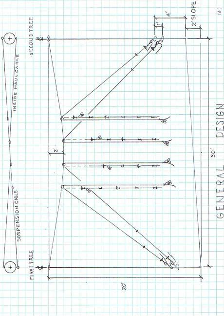
3 AERIAL FOOD STORAGE CABLE SYSTEM The Carolina Mountain Club (CMC) had a number of bear sightings at shelters during 2007 and considerable problems with them getting hikers food in We have now installed aerial food storage cables (bear cables) at all ten of our shelters with a second cable in the tent pad area of the Roaring Fork shelter. The Great Smoky Mountains National Park September, 1999 publication BACKCOUNTRY FOOD STORAGE CABLE SYSTEM was used as the basis for our design. A list of materials and vendors is on page 5. The CMC section of the Appalachian Trail has no restrictions on the number of hikers that can be at a shelter, so we have no control over the total amount of food sacks and backpacks that the hikers will want to lift up on the aerial food storage cable(bear cable). We have assumed that 16 hikers will each want to pull up a pack weighing about 31 pounds for a total on each of four pulleys of 125 pounds (250 pounds per pulley). See GENERAL DESIGN (pg 6) which is for trees 30 feet apart and with a slope of 2 feet between the bases. The graph, EFFECT OF SAG ON CABLE STRESS (pg 7), shows how rapidly the stress rises as the amount of sag at the middle of a 30 foot cable decreases and also shows the breaking strengths of 3/16 and 1/4 SS cable. We chose a minimum sag of 2 feet and 1/4 inch diameter stainless steel (SS) for our cables because this puts onto the suspension cable a total stress no more than 50% of the breaking strength. This 2:1 safety factor will prevent cable breakage from infrequent overloads and any dynamically created forces when the load is being pulled up to the top. We chose 3 diameter pulleys for the haul cables based on recommendations available in the literature. However, subsequent recommendations from a cable vendor were that 2 diameter pulleys are acceptable for use with 3/16 diameter SS haul cables. We purchased 3 pulleys that have bronze bushings and cotter pins holding the shaft so they can be taken apart and greased.our shelter installations have the 3 pulleys but we will probably use smaller pulleys for cables at our camping areas because the loads will be less. Some of the CMC shelters are a considerable hike from the nearest road access so we decided to carry in no more than the amount of material that was needed for that site. We did a preliminary survey to find two sturdy trees that were about 30 feet apart, accepting trees from 26 feet to 34 feet apart. We measured the span between opposite sides of the trees and the slope between the bases. For no slope, we arbitrarilly chose a First Tree which will have the anchor eyebolt at 20 feet above the ground. The Second Tree eyebolt is the same when there is no slope, but if there is slope, the uphill tree is the Second Tree and the eyebolt will be at 20 feet minus the slope and on the opposite side from the First tree. The eyebolts for the outside haul cables are on the same side as the suspension eyebolts and four feet above the ground. The inside haul cable eyebolts are on the other side of the tree and one foot below the outside eyebolts. This makes the outside haul cable too short to be connected to the inside haul cable eyebolt, thereby physically identifying the two cables. (1)
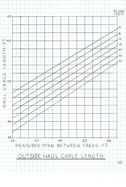
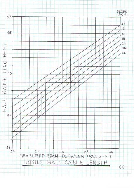
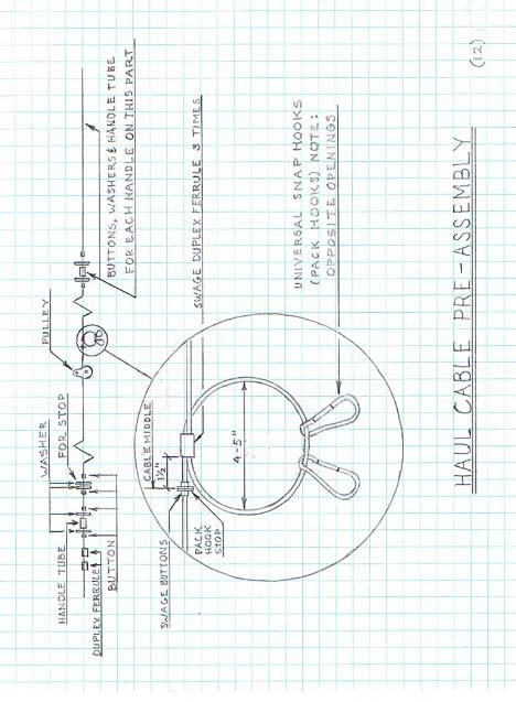
4 The length of the suspension cable is the span between the trees plus two feet for connecting to the two eyebolts and some spare. The lengths of the four haul cables are determined from the two graphs, OUTSIDE HAUL CABLE LENGTH (pg 8) and INSIDE HAUL CABLE LENGTH (pg 9). These graphs include additional cable for the loop that holds the pack hooks and to compensate for minor differences in dimensions at the site. Use zero slope for the two cables that connect to the First tree. Slope only affects the cables that connect to the Second tree. We usually round up the length to be safe. We have found that cutting the cables without fraying can best be done by first wiping on at the cut site a coating of Goop or Liquid Nails Clear and allowing it to dry thoroughly before cutting. Then, some additional glue can be put onto the cut ends to hold all the strands tight while putting on any of the tight fitting swaging buttons, handles, etc. We prepared the suspension cable as shown on drawing SUSPENSION CABLE ASSEMBLY (pg 10) for our first installations but carried in all the parts for the haul cable handles and tried to assemble them on-site after determining there the number of handles we wanted to install. This proved difficult, if we had to cut any of the cables and could not wait for the glue to dry. Cable strands would get pulled up, forcing us to again cut the cable. We therefore went to calculating the number of handles for each haul cable so that we could completely pre-assemble each of them at the same time we pre-assembled the suspension cable. We lay out a 1/4 = 1! scale drawing of the entire system to calculate the number of handles needed on each haul cable. HAUL CABLE HANDLES (pg 11) shows how just the Outside cable at the First Tree of a 30 foot span with a 2 foot slope is calculated. In PROCEDURE A, the Pack Hook Stop is drawn 4feet above the ground on the load side cable. This puts the pack hooks about 3 feet above the ground. The distance from the Pack Hook Stop to the intersection of the cable with the suspension cable (the circle) is measured and transferred to the tree side part of the cable, as shown. The Stop will be against the pulley when the Pack Hook Stop is 4 feet from the ground. Mark the tree side cable at the back of the mouse barrier in the handle 20 from the haul cable eyebolt. Transfer the measurement A to the cable as it will be when the pack hooks are as shown in PROCEDURE B. Measure 5! up from the ground to what will be the first handle for pulling up the packs. The difference B, is the length of cable that will have all of the handles, as shown. Measure this and calculate the number needed when they are ideally 24 to 30 apart. All of these measurements can be done on the scale drawing. The parts for the calculated number of handles can then be put onto each marked haul cable as in HAUL CABLE PRE-ASSEMBLY (pg 12). Pre-assembly and on-site assembly of the suspension cable are combined as shown on SUSPENSION CABLE ASSEMBLY (pg 10) because the on-site amount is minor. These are the pizza pan squirrel and plastic tube raccoon barriers, as shown in the GSMNP publication, which are put on the suspension cable on-site. We assembled he pizza pans as shown on PIZZA PAN ASSEMBLY (pg 13) to prevent them from oscillating in the wind. The lamp tube used is slightly larger in diameter than 3/8, therefore, the lock nuts for use with that tube must be used. The pans are 12 diameter aluminum with a rolled edge. Note that the rim faces inward. The plastic tubes are 2 X 20 PVC pipe which are loose on the cable and can role when stepped upon. (2)
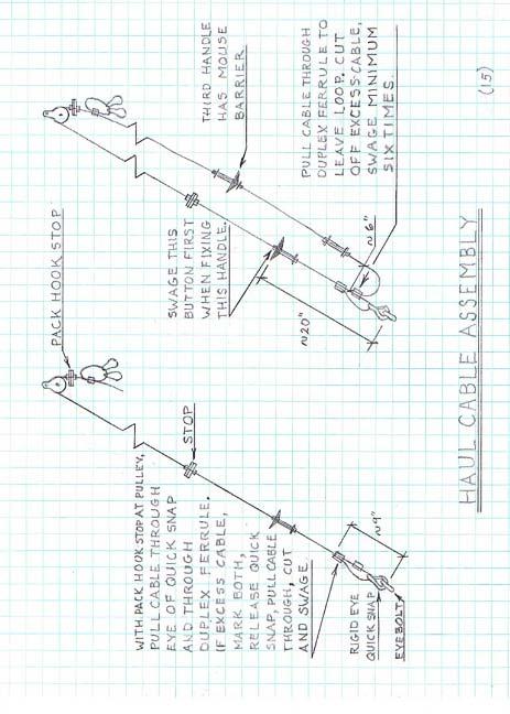
5 Lay out the suspension cable on the ground at the site, put on the pizza pan assemblies and swage the buttons. Put on the tubes and clips, taping the clips so they will not slide. Fasten a 40 foot long haul rope a short way past the clips at the First Tree end. Connect all of the pulleys on the haul ropes to their correct rapid link on the suspension cable and tape together the two ends of each cable. The person on the ladder uses a tool rope for bringing up tools, eyebolts, etc., that is about 23 feet long, has a hook on the bottom, and is marked at 20 feet and 18! feet from the hook. The person marks the side of First Tree at the 20 foot and 18 foot positions by lowering the tool rope until the hook touches the ground. A drill is brought up and the pilot hole drilled for the eyebolt at the 20! mark. The eyebolt wih thimble attached is then turned into the tree with a pipe hammer made from 1/2 x 12 pipe, tee, close nipple, cap, and plug. The haul rope is fed down through the eyebolt to the person on the ground who pulls until the cable can be fed through the eyebolt and the mark at 8 inches from the end is even with the tip of the thimble as in SUSPENSION CABLE ANCHORS (pg 14). Fasten clips to cable as shown and tighten thoroughly. Mark or fasten horizontally a piece of tape to the side of the tree facing the Second Tree at the 18 foot mark. Remove the haul rope and transfer it to the other end of the suspension cable. Mark the eyebolt spot on the second tree at 20 feet less any known slope. Also, mark or put tape on the ladder side toward the First Tree two feet down from the eyebolt spot. Install the eyebolt and feed the haul rope as before. As soon as the cable end is through the eyebolt, fix a sight-line from the mark or tape on the ladder to the tape on the First Tree. Stop pulling the cable when the center part reaches the sight-line. Fasten the cable as shown in SUSPENSION CABLE ANCHORS. As previously described, the outside haul cable eyebolts are directly under the suspension cable eyebolts and four feet above the ground and the inside eyebolts are on the opposite side of the tree and one foot down. We made a sliding stop from upholstery foam (a sponge could also be used) that is clamped to the tree side of the haul cable so that it will slide but stay in position when the cable is pulled to where the Pack Hook Stop is at 4 feet from the ground. Mark the cable and swage the Stop at that position. See HAUL CABLE HANDLES. Fasten a rope to the tree side cable section and remove the tape holding together the two sections. Connect the quick latch to the eyebolt, pull the cable up through the latch eye and through the upper duplex ferrule as shown in HAUL CABLE ASSEMBLY (pg 15). Remove most of the slack in the cable and mark the ferrule position as shown. Unfasten the quick latch and pull more of the cable through the ferrule in order to cut off the excess. Return the ferrule to the marks and swage three or four times. Connect the quick latch to the eyebolt. pull the load side cable through the remaining duplex ferrule to remove most of the slack. Mark the cables, disconnect the quick latch and again pull through enough cable to cut off the excess. Return to the marks and swage a minimum of FOUR, preferably FIVE times. Two of these connections have failed when swaged only three times but failure could not be duplicated when a test section was loaded to 145 pounds. But play it safe! This is the connection that will come apart when the system is overloaded. (3)
6 Assemble the MOUSE BARRIER (pg 16) to the tree side handle with the cone in the proper direction, 20 inches from the eyebolt, as shown in HAUL CABLE ASSEMBLY. Swage the upper button first for this handle then push up the rest of the handle before swaging the lower button. Swage a handle at the five foot mark with the Stop against the pulley and the Pack Hook Stop at 4 feet from the ground as shown in B of HAUL CABLE HANDLES. Measure the actual length of cable, similar to B, between the two handles and calculate the distance needed for handle separation. Put the second mouse barrier on the second handle from the quick latch and swage all handles. Repeat for each haul cable. Put up a sign on the most visible tree to tell the hikers how to use the system. We are using the sign shown on page 17, FOOD STORAGE CABLE.
7 (4) MATERIALS & EQUIPMENT ITEM VENDER 3 dia Gable (fixed eye) blocks Deuer Manufacturing, Inc P.O. Box 4014 Dayton, OH /8 X 4 1/2 forged lag eye bolts Bolts & Nuts, Inc 3/8 X3 galv lag eye bolts 18 Sweeten Creek Road 1/4 X 1 1/4 SS fender washers Asheville, NC /8 X 1 1/2 SS fender washers 30 HIT swager w/cutter American Presto Corporation 4001 Santa Ana Street Ontario, CA 6! Adjustable Lanyard Forestry Suppliers, Inc 10! Sectional Ladder, aluminum P.O. Box 8397 Jackson, MS /4 7 X 19 SS cable American Cable & Rigging Supply, Inc 1/4 SS wire rope clamps P.O. Box 546 1/4 wire rope thimbles Arden, NC /4 copper button stops 3/16 copper button stops 3/16 copper duplex ferrules 3/8 SS universal snap hooks 3/8 SS rapid links 12 AL pizza pans Swanner Restaurant Equipment Company, Inc 604 Seventh Avenue East Hendersonville, NC X 10! PVC pipe Lowe!s Home Centers, Inc 3/4 SS rigid eye quick snaps 18 swaging tool 1/8 X 24 threaded pipe 3/16 Diamond Braid rope 1/4 braided PVC tubing 3/4 X 66! red tape 1/2 X 12 galv pipe 1/2 galv tee 1/2 galv close nipple 1/2 galv cap 3/16 7 X 19 SS cable 1/8 X 24 lock nuts 20 X 10! aluminum flashing 1/8 X 1/8 pop rivet 1/2 pt Rustoleum primer paint The Home Depot
8 (5)
9
10
11
12
13
14

15
16
17
18
19
PR-429BF-600M. Bell 429 Blade Fold Kit Operations Manual
 Table of Contents Table of Contents... 1 Record of Revisions... 2 References... 3 Introduction... 4 Contact Information... 4 Prerequisites... 5 First Time Use... 6 Blade Clamp Placement... 6 Blade Clamp
Installation Instructions for the Rolltec Adalia X3M Extenda Awning
 Installation Instructions for the Rolltec Adalia X3M Extenda Awning Questions? Call Rolltec at 1-800-667-0474 General Tool Requirements Table of Contents Available installation brackets Side dimensions
* * 4023 KR. Step 1 Prepare the Keyed Removable Unit. Not for use on electric or fire rated removable mullions
 condition. *64009-00* 64009-00 Keyed Removable Mullions 403 KR Installation Instructions Not for use on electric or fire rated removable mullions This kit includes the following parts: (Not to scale) 5/6
Otter Pro X-Over Lodge Installation and Set-Up Instructions
 Otter Pro X-Over Lodge Installation and Set-Up Instructions Otter Pro X-Over Lodge Fits Magnum Otter II & Pro Sled Only Parts Identification and Check List MODEL NUMBERS: Complete Pkg Pro X-Over Lodge
Installation Instructions for the Rolltec Bravo Awning
 Installation Instructions for the Rolltec Bravo Awning Questions? Call Rolltec at 1-800-667-0474 Table of Contents Available installation brackets Side dimensions of various installations Determining installation
Installation Instructions for the Rolltec Physique XL Awning
 Installation Instructions for the Rolltec Physique XL Awning Questions? Call Rolltec at 1-800-667-0474 General Tool Requirements Table of Contents Available installation brackets Side dimensions of various
Roller Bar End Cap (w/round Drive Shaft) Replacement Instructions for Vista and Motorized Awnings * Helpers needed *
 Replacement Instructions for Vista and Motorized Awnings * Helpers needed *") RETRACTABLE AWNINGS For Technical Support visit us at www.sunsetter.com/ownerscorner or Call Toll Free 800-670-7071 Fax 877-224-4944 Roller Bar End Cap (w/round Drive Shaft) Replacement Instructions for
RETRACTABLE AWNINGS For Technical Support visit us at www.sunsetter.com/ownerscorner or Call Toll Free 800-670-7071 Fax 877-224-4944 Roller Bar End Cap (w/round Drive Shaft) Replacement Instructions for
Alien Flier Zip Line Products Installation/Owner s Manual
 Alien Flier Zip Line Products Installation/Owner s Manual 1 Table of Contents SAFETY PLEASE READ CAREFULLY... 4 Constructing your Zip Line Xtreme Models... 6 Installing your Alien Flier Trolley on an Existing
P3000 UNIVERSAL Clamp-On
 IHI INSTRUCTION MANUAL Required Tools P3000 UNIVERSAL Clamp-On Wrench Allen Key P3001 65 ENDCAPS P3011 65 BLACK P300 7 ENDCAPS P301 7 WHITE P3003 ENDCAPS P3013 SILVER PART# DESCRIPTION ENDCAPS SIDE SUPPORTS
INSTALLATION INSTRUCTIONS
 INSTALLATION INSTRUCTIONS KR54, KR1654, & KR4954 Keyed Removable Mullion NOT FOR USE ON ELECTRIC OR FIRE RATED MULLIONS. This kit includes the following parts: (Not to scale) WARNING Remove key, reinstall,
AND LOAD CANOPY RACK SPECIFICATIONS
 8MAY15 INSTRUCTIONS for the LOCK AND LOAD CANOPY RACK SPECIFICATIONS and SAFE LOADING REQUIREMENTS The Lock and Load ladder carrier for Truck Caps is a rack designed to mount to the top of a pickup truck
IMPORTANT OWNER-OPERATOR INSTALLATION INSTRUCTIONS. Part # A7006
 IMPORTANT OWNER-OPERATOR INSTALLATION INSTRUCTIONS Part # A7006 Parts List Wobble Stopper Body Wobble Stopper Shaft Camper Bracket Lower Bracket Assembly Upper Bracket Upper Bracket Clamp 3/8 SAE Flat
Otter Pro XT Cabin Installation and Set-Up Instructions
 Otter Pro XT Cabin Installation and Set-Up Instructions Otter Pro XT Cabin Fits Medium Otter Pro and Otter II Sled Only Parts Identification and Check List MODEL NUMBERS: Complete Pkg Pro XT Thermal Cabin
Solar Power Shade INSTRUCTION MANUAL
 INSTRUCTION MANUAL 20 June 2006, Revision Initial Release 26 September 2006, version 2 Powerfilm, Inc. 2337 230th Street Ames, IA 50014 (515) 292-7606 Web Site: www.powerfilmsolar.com Table of Contents
INSTRUCTION MANUAL ALEKO RETRACTABLE AWNING
 INSTRUCTION MANUAL for ALEKO RETRACTABLE AWNING www.alekoproducts.com FAILURE TO FOLLOW THESE INSTRUCTIONS MAY RESULT IN PERSONAL INJURY! 1 Important Safety Precautions WARNING NOTE: FOR PERSONAL SAFETY,
Installation and User s Manual 12 x 10 MOTORIZED AWNING
 12 x 10 MOTORIZED AWNING Installation and User s Manual 12 x 10 MOTORIZED AWNING 088-1763-0 Stop Please read and understand this manual before any assembly or use of this product. Before beginning assembly
BEV-TENT COMPONENTS. Made in South Africa
 BEV-TENT COMPONENTS REB MARKETING Distributing Agent Tel: (011) 452 9131 Cell: 072 965 6792 Fax: (011) 609 4615 15 Imvubu Road, Sebenza Ext 6, Edenvale orders@rebmarketing.co.za BEV-TENT 001 90 deg Elbow
Instruction Manual Remote Swabbing and Microbiological Sampling and Teflon template tools Version , Rev.0
 ASSEMBLY AND OPERATIONAL INSTRUCTIONS The remote swabbing and microbiological sampling tool and the Teflon template tool are shipped partially assembled. Complete assembly instructions are provided below:
Otter XT 650 Cabin Installation and Set-Up Instructions
 Otter XT 650 Cabin Installation and Set-Up Instructions Otter XT 650 Cabin Fits Medium Otter Wild Sled Only Parts Identification and Check List MODEL NUMBERS: Complete Pkg Otter XT 650 Cabin 200891 2 1
MYRIAD Banner Stand is a trademark of Skyline Exhibits. Patent Pending PN32294-B. MYRIAD Banner Stand
 is a trademark of Skyline Exhibits Patent Pending 1.1 1. Banner Stand Setup 1.1 Remove banner stand from standard case or Arrive Portable Display & Workstation and assemble pole. 1.2 Insert pole into base
Otter XT Cabin Installation and Set-Up Instructions
 Otter XT Cabin Installation and Set-Up Instructions Otter XT Cabin Fits Medium Otter Wild Sled Only Parts Identification and Check List MODEL NUMBERS: Complete Pkg Otter XT Cabin 200962 2 1 PARTS LIST
BEV-TENT COMPONENTS. Made in South Africa
 BEV-TENT COMPONENTS REB MARKETING Distributing Agent Tel: (011) 452 9131 Cell: 072 965 6792 Fax: (011) 609 4615 15 Imvubu Road, Sebenza Ext 6, Edenvale orders@rebmarketing.co.za BEV-TENT 001 90 deg Elbow
--- BIG LEAGUE BATTING CAGE ---
 --- BIG LEAGUE BATTING CAGE --- BGLC-7500 Call Jaypro Sports Equipment at 1-800-243-0533 during regular business hours for technical support. www.jaypro.com Rev-B Page 1 of 22 IMPORTANT NOTICE: 1. BEFORE
Otter Pro XT 1200 Cottage Installation and Set-Up Instructions
 Otter Pro XT 1200 Cottage Installation and Set-Up Instructions Otter Pro XT 1200 Cottage Fits Small Ultra-Wide Otter Pro and Otter II Sled Only Parts Identification and Check List MODEL NUMBERS: Complete
80070 TOP MOUNT CAMPER SHELL and TRANSIT CONNECT RACK TMCS_3:1
 ASSEMBLY INSTRUCTIONS for : 80070 TOP MOUNT CAMPER SHELL and TRANSIT CONNECT RACK TMCS_3:1 (916) 638-8703 (800) 343-7486 11261 Trade Center Drive Rancho Cordova, CA 95742 www.kargomaster.com Transit ASSEMBLY
Cabinet Mount Assist Lift n Lock Instructions
 Cabinet Mount Assist Lift n Lock Instructions PART LIST 2 @ Gas Cylinder 1 @ Lock Bar 2 @ Rubber Sleeve (preset) 4 @ Stopper Pin (2pcs preset) 4 @ Saddle Block 8 @ 19mm Black PVC Cap 5 @ 14mm Black PVC
User s Manual Trampoline 8
 User s Manual Trampoline 8 Model! WARNING Read all precautions and instructions in this manual before using this equipment. Save this manual for future reference. Maximum user weight 17 lbs. ASSEMBLY IMPORTANT
Auxiliary 63.5l Fuel Tank Ford/Mazda Pick-up Truck 2012-Current READ ME! IMPORTANT WARNING!
 Auxiliary 63.5l Fuel Tank Ford/Mazda Pick-up Truck 2012-Current ENG FTFM006 90 min READ ME! Thank you for purchasing a Front Runner Ford/Mazda Pick-Up Truck 2012 - Current Fuel Tank. Before you start,
BEV-TENT COMPONENTS AGENTS. GAUTENG REB MARKETING-Nick Tel:- (011) Fax:- (011)
 Fax:- (011)") BEV-TENT COMPONENTS FACTORY KNYSNA Tel:- (044) 3823215 / 3824707 / 3823152 Fax:- (044) 3825709 Cel:- 0825543947 info@bgboats.co.za accounts@bgboats.co.za orders@bgboats.co.za - Ordering www.bev-tent.co.za
BEV-TENT COMPONENTS FACTORY KNYSNA Tel:- (044) 3823215 / 3824707 / 3823152 Fax:- (044) 3825709 Cel:- 0825543947 info@bgboats.co.za accounts@bgboats.co.za orders@bgboats.co.za - Ordering www.bev-tent.co.za
Vanagon Ladder Kit Assembly & Installation Instructions
 Rocky Mountain Westy Vanagon Ladder Kit Assembly & Installation Instructions Introduction Thank you for purchasing the Rocky Mountain Westy Vanagon Ladder Kit. We pride ourselves in the products we develop
Product Description of Klozit Sliding Glass Door Closing and Latching System
 Product Description of Klozit Sliding Glass Door Closing and Latching System KLOZIT Door Closers: The Klozit sliding glass door closer is based upon a gas spring, similar to those found in car hatchbacks.
FLEX KEY ASSEMBLY. ..._ o RAFTER ARM TUBE MAIN ARM TUBE CAP NUT CLAW HINGE
 ZIP DEE Inc. 96 Crossen Ave. Elk Grove Village, IL 60007(847)437-0980 (800)338-2378 HEAD CASTING AWNING RAIL FLEX KEY ASSEMBLY..._ o GM1 Installation Instruction GMC Motorhome RAFTER ARM TUBE MAIN ARM
RAFTER VI. Installation and Operation CAREFREE WITH AUTOMATIC AWNING SUPPORT. RV Accessory PRODUCT OVERVIEW
 CAREFREE RAFTER VI RV Accessory WITH AUTOMATIC AWNING SUPPORT Installation and Operation PRODUCT OVERVIEW The gives the awning user the ability to easily tighten the center fabric when the awning is extended.
READ ME FIRST! IMPORTANT WARNING! ENG. Roof top tent
 Roof top tent ENG TENT031 220 min READ ME FIRST! Thank you for purchasing a Front Runner Roof Top Tent. Before you start, take a moment to familiarize yourself with these Fitting Instructions and the components
INSTALLATION INSTRUCTIONS AND OWNER'S MANUAL AWNINGS. For trailers & motor homes with straight sides TOOLS REQUIRED
 AWNINGS INSTALLATION INSTRUCTIONS AND OWNER'S MANUAL For trailers & motor homes with straight sides TOOLS REQUIRED 1/4" electric drill Ratchet handle kit 3/8" & 7/16" socket No. 1 and No. 2 screwdriver
INSTALLATION INSTRUCTIONS for vertical awnings
 Custom made Awnings and Blinds Item No 0759 INSTALLATION INSTRUCTIONS for vertical awnings IMPORTANT INFORMATION BEFORE INSTALLING YOUR Updated 08/09/15 AN AWNING INSTALLATION IS A HOME IMPROVEMENT PROJECT
IMPORTANT OWNER-OPERATOR INSTALLATION INSTRUCTIONS C2204A
 IMPORTANT OWNER-OPERATOR INSTALLATION INSTRUCTIONS C2204A Warnings Truck Bed and Camper Protection Torklift does not recommend installing your camper on top of a plastic bed liner (or other compressible
DO NOT use Alien Flier Zip Line Products until you have read and fully understand the SAFETY WARNINGS below!
 SAFETY WARNING DO NOT use Alien Flier Zip Line Products until you have read and fully understand the SAFETY WARNINGS below! Assumption of Risk Zip line construction and use can be dangerous. Ensure you
SOLHARO ASSEMBLY & INSTALLATION INSTRUCT IONS
 A. Introduction: SOLHARO ASSEMBLY & INSTALLATION INSTRUCT IONS Rev. 01/30/2012 The Solharo is an external, retractable, tensioned sun shading system designed to fit over a sunroom or wood pergola. The
Insruction manual Dukki
 Insruction manual Dukki Introduction Pg. 1 Product description Pg. 2 3 Assembly and disassembly Pg. 4 Installation and adjustment Pg. 5 12 Maintenance Pg. 13 Parts Pg. 14-17 INDEX 1. Introduction 1 2.
Alien Flier Zip Line Products Installation/Owner s Manual
 Alien Flier Zip Line Products Installation/Owner s Manual 1 Table of Contents SAFETY PLEASE READ CAREFULLY... 4 Explorer Zip Line EZ Up Cable Kit Installation... 5 Xtreme Zip Line EZ Up Cable Kit Installation...
Core Systems Installation Instructions
 185-3017 185-3018 185-3517 607-0149 WLH 09/17/18 TABLE OF CONTENTS ***Assembly*** Roller Tube Assembly Roller Tube Assembly... Standard Application Attaching Tarp to Roller Tube - Standard... Installing
Gas Go Anywhere /23/01
 Gas Go Anywhere 55014 02/23/01 FOR OUTDOOR USE ONLY This grill does not include an LP fuel tank. Check Package Contents You should have received the parts listed below. While we give much attention to
Antenna Tower Positioning System
 Model 1052 Antenna Tower Positioning System User Manual (Antenna not included) ETS-Lindgren L.P. reserves the right to make changes to any product described herein in order to improve function, design,
HANDLE AND WHEEL KIT INSTALLATION
 HANDLE AND WHEEL KIT INSTALLATION Select EB and EM Series Generators Honda Power Equipment Your generator is equipped with a wheel kit and folding handle kit for easy transport and convenient storage.
OPERATOR INSTRUCTION MANUAL INCLUDING REPAIR PARTS FOR MODULAR GENERAL PURPOSE TENT SYSTEM (MGPTS) TYPE I
 TYPE I") OPERATOR INSTRUCTION MANUAL INCLUDING REPAIR PARTS FOR MODULAR GENERAL PURPOSE TENT SYSTEM (MGPTS) TYPE I Johnson Outdoors Gear, Inc. Eureka! branded tent products 625 Conklin Road Binghamton, NY 13903
OPERATOR INSTRUCTION MANUAL INCLUDING REPAIR PARTS FOR MODULAR GENERAL PURPOSE TENT SYSTEM (MGPTS) TYPE I Johnson Outdoors Gear, Inc. Eureka! branded tent products 625 Conklin Road Binghamton, NY 13903
Genesis. Side Burner Accessory Installation. Step 3. Step 1. Step 2. For use with Genesis Gas Barbecues Only
 Genesis Side Burner Accessory Installation For use with Genesis Gas Barbecues Only Step 1 WARNING: All gas controls and supply valves should be in the OFF position. You will need: Side burner assembly
Installation Guide Cable
 Installation Guide Cable Thank you for selecting a DuctSox System. This guide will be helpful for the installation of a Cable System. Sections of fabric will be labeled, assembled, bagged, and boxed for
General Purpose Shelter
 General Purpose Shelter 0' x 0' x ' ( x x. m) ASSEMBLY MANUAL Model NO.: - Tools required for assembly (not included) TM TABLE OF CONTENTS Important safety instructions... Intended use... Parts list......
Knives, Cutters & Scrapers
 Knives, Cutters & Scrapers - 261 - Utility Knives T23216 T232 T23218 Snap-Off Knives SK4 Steel blades Stores up to 3 replacement blades Blade sections snap off providing sharp cutting point Stainless steel
INSTALLATION INSTRUCTIONS
 INSTALLATION INSTRUCTIONS Accessory FABRIC ROOF/ REAR PANEL (5P) P/N 0SR85-HL4-222A (Black) 0SR85-HL4-221C (Camo) Application SXS1000M5P/M5D Honda Dealer: Please give a copy of these instructions to your
Installation Instructions Traditional Awnings in a box Classic Awnings in a Box
 Installation Instructions Traditional Awnings in a box Classic Awnings in a Box Basic Tools Required (not included) Tape Measure & Pencil Level Phillips Screwdriver Drill with ¼ bit (Cement or Masonry
Tuf-Lite and Tuf-Lite II Fans 6000M Series Hub
 Tuf-Lite and Tuf-Lite II Fans 6000M Series Hub INSTALLATION MANUAL Adjustable Pitch Fan Assembly 32.8 or 10 Meter Diameter Hudson Tuf-Lite and Tuf-Lite II fan blades Hudson Tuf-Lite (black) fan blades
TITAN Fuel Tanks. INSTALLATION INSTRUCTIONS G e n e r a t i o n V
 TITAN pt. no.: 02 0000 0128 Important: Please read these instructions carefully and completely before starting the installation. TITAN Fuel Tanks INSTALLATION INSTRUCTIONS G e n e r a t i o n V Extended
Fiberglass 80 meter Vertical BASE
 Fiberglass 80 meter Vertical - Revised: 2015-11-06 One antenna in use at K0MPH is a fiberglass 80 meter vertical. The supporting structure is made of fiberglass tubing but the radiation is from a wire
KAWNEER 1786 RIM EXIT DEVICE
 FEBRUARY, 2015 1 DOOR STILE Device C L 40" 41-9/32" Cylinder C L Bottom of door RIM EXIT DEVICE LOCATION DOGGING KEY EXIT DEVICE FILLER PLATE CYLINDER & CYLINDER RING HOUSING COVER CYLINDER INSTALLATION
DURA WHEEL CHAIR LOCKER ASSEMBLY INSTRUCTIONS
 DURA WHEEL CHAIR LOCKER ASSEMBLY INSTRUCTIONS 1. Locate a Frame and Door: Start by locating a frame and door. 2. Front Frame: Now stand up the frame and door in the desired assembly area. 3. Exterior Wall:
Important! Read all of these instructions before assembling or riding the glider. For questions or help please call Glide Bikes at
 Go Glider Manual Congratulations on your purchase of the Go Glider! Your glider is designed for years of nearly carefree use by your child. These instructions include how to set up your glider and maintenance
BowDown. MiniMuM Crossbar spread 24 (61CM) Steel Hook (2X) Buckle Strap (2X) Plastic Tube (2X) Plain Strap (2X) SHORT BLACK T-BOLT (2x) BOWDOWN (2x)
 Steel Hook (2X) Buckle Strap (2X) Plastic Tube (2X) Plain Strap (2X) SHORT BLACK T-BOLT (2x) BOWDOWN (2x)") BowDown MiniMuM Crossbar spread 24 (61CM) Heavy Duty strap (2x) SHORT BLACK T-BOLT (2x) BOWDOWN (2x) Bow Stern Tie Down Buckle Strap (2X) Plastic Tube (2X) Plain Strap (2X) Steel Hook (2X) IMPORTANT WARNING
BowDown MiniMuM Crossbar spread 24 (61CM) Heavy Duty strap (2x) SHORT BLACK T-BOLT (2x) BOWDOWN (2x) Bow Stern Tie Down Buckle Strap (2X) Plastic Tube (2X) Plain Strap (2X) Steel Hook (2X) IMPORTANT WARNING
SAFETY GUIDELINES FOR DIY TENTS
 SAFETY GUIDELINES FOR DIY TENTS Please read carefully and fully before starting assembly of the tent 1. The installer is solely responsible for evaluating the site and proper securing method determined.
Auto Rewind Hose Reel 10M / 20M / 30M Models
 Auto Rewind Hose Reel 10M / 20M / 30M Models Instruction Manual 10M / 20M / 30M Auto Rewind Hose Reel Installation, Hose Replacement and Troubleshooting Guide Product Codes: 1110H / 1120H / 1130H Models
Solera Classic Awning OEM INSTALLATION MANUAL
 Solera Classic Awning OEM INSTALLATION MANUAL TABLE OF CONTENTS System and Safety Information 2 Preparation 3 Resources Required 3 Installation 3 Installing the Awning Rail (If Necessary) 3 Assembling
Installation Guide: Round Trampoline
 Trampolines & trampoline parts designed to survive in the harsh Oz climate. www.oztrampolines.com.au Installation Guide: Round Trampoline Safety Tips Here at Oz Trampolines we are passionate about your
14' x 32' x 12' Round Top Round Style Shelter Assembly Instructions
 14' x 32' x 12' Round Top Round Style Shelter Assembly Instructions Description Model # 14' x 32' x 12' RoundTop Garage - Gray 62669 Recommended Tools Please read instructions COMPLETELY before assembly.
COOPER FREESTANDING TUB FAUCET INSTALLATION
 SKU(s): 940972 COOPER FREESTANDING TUB FAUCET INSTALLATION BEFORE YOU BEGIN We recommend consulting a professional if you are unfamiliar with installing plumbing fixtures. Signature Hardware accepts no
INSTANT GARAGE MODEL NO: CIG81224 ASSEMBLY INSTRUCTIONS PART NO: ORIGINAL INSTRUCTIONS
 INSTANT GARAGE MODEL NO: CIG81224 PART NO: 3503578 ASSEMBLY INSTRUCTIONS ORIGINAL INSTRUCTIONS GC1117 INTRODUCTION Thank you for purchasing this CLARKE Instant Garage. When erected, the CIG81224 garage
Thomas Scientific Swedesboro, NJ U.S.A.
 Thomas Scientific Swedesboro, NJ 08085-0099 U.S.A. Wiley Laboratory Mill, Model 4 3375-E10 (115 V, 50/60 HZ) USE AND CARE OF CATALOG NUMBER: 3375-E10 Wiley Laboratory Mill, Model 4 (115 V, 50/60 HZ) UNPACKING
Contents. Awnings USA - Full Protective Hood Manual Instructions ft 11" - 11ft 6" Awnings
 Awnings USA - Full Protective Hood Manual Instructions Contents Warning We recommend that two or more people are required to lift the awning into place. 4ft 11" - 11ft 6" Awnings 8 x Expansion bolts **
π H-3505 GARAGE CANOPY PARTS SAFETY uline.com TOOLS NEEDED 10' X 20' X 8'
 π H-3505 GARAGE CANOPY 10' X 20' X 8' 1-800-295-5510 uline.com TOOLS NEEDED Safety Glasses Wrench or Socket 9/16" or 14mm Tape Measure Phillips Screwdriver Rubber Mallet PARTS Cables x 5 2-way Corner Foot
WIDESPREAD LAVATORY MODELS WITH HI-ARC SPOUT
 5951, 5961, 5981, 5983, 5993 SERIES MT122B INSTALLATION INSTRUCTIONS THESE INSTRUCTIONS MUST BE LEFT WITH HOMEOWNER WIDESPREAD LAVATORY MODELS WITH HI-ARC TRADITIONAL CROSS NOTE: Handle Inserts are not
Manual Awning. Assembly Instructions. Product No Toll-free:
 Manual Awning Product No. 088-30- Instructions Toll-free: -877-483-679 IMPORTANT: Please read this manual carefully before beginning assembly of this product. Keep this manual for future reference. 3 Table
Urea/Adblue Hose Reel
 www.scintex.com.au sales@scintex.com.au Model: SHR3408 Urea/Adblue Hose Reel Product Manual Specifications Spring driven drum: for automatic rewind. Locking ratchet: to maintain the desired length of hose
POP-UP OPTION USER HARDWARE MANUAL. EdgeTech 4 Little Brook Road West Wareham, MA _REV_B 8/29/2018
 POP-UP OPTION USER HARDWARE MANUAL 0019850_REV_B 8/29/2018 EdgeTech 4 Little Brook Road West Wareham, MA 02576 Tel: (508) 291-0057 Fax: (508) 291-2491 www.edgetech.com ii The information, figures, and
MACHETES & MACHETE SHEATHS HUDSON BAY AXE SINGLE EDGE AXE GUARD DOUBLE EDGE AXE GUARD LADDER PLATFORM. Machete CAT. NO.
 Phone: 800-227-4255 www.hallssafety.com Fax: 724-458-0592 MACHETES & MACHETE SHEATHS Machete 2PMA18-18 Blade 2PMA22-22 Blade High quality machete. High carbon tempered steel blade. Black poly handle with
Honda Ridgeline Installation Instructions
 Honda Ridgeline Installation Instructions READ THIS... If you read these instructions from beginning to end before starting you will probably not need to look at them again during the installation, but
M A N U A L ARCTIC SHELTER LTD. OFFICE WATER ST. VANCOUVER, BC V6B 0M9 CANADA
 ARCTIC SHELTER LTD. OFFICE 8098 200-375 WATER ST. VANCOUVER, BC V6B 0M9 CANADA Help Desk: arctic@hdshelter.com 2016 Arctic Shelter Ltd. All Rights Reserved. NOT FOR SALE INSTRUCTION M A N U A L 2016-2017
IMPORTANT OWNER-OPERATOR INSTALLATION INSTRUCTIONS C3215/C3215A
 IMPORTANT OWNER-OPERATOR INSTALLATION INSTRUCTIONS C3215/C3215A Minor movement (or settling) can occur in some incidental harsh driving conditions (On or off road). A rubber bed mat is not a requirement
Door Bushing Replacement & Latch Adjustment Monaco Group Coaches
 Door Bushing Replacement & Latch Adjustment Monaco Group Coaches Contents Door Latch Adjustment & Repair... 1 Symptoms:... 1 Replacing the bushing VS. Adjusting the latch rods.... 1 How the bushing works....
SteadiCam Parts List*
 SteadiCam Parts List* A. 1 Bogen 3232 Monopod Swivel Tilt Head B. 1 1/2 internal to 1/2 external brass bushing flare adapter (part 9402249 at osh.com¹) C. 2 3/8 internal to 1/2 external brass bushing flare
* * KR54-F, KR9854 & KR9954 Installation Instructions. Read All Warnings Before Starting Installation! Index:
 *941061-00* 941061-00 Keyed Removable Mullion KR54-F, KR9854 & KR9954 Installation Instructions CLASSIFIED CLASSIFIED C Read All Warnings Before Starting Installation! Index: General Information ----------------
4-foot Economy Sign Post. 4-foot post is rated at 2 pounds per foot. 7-foot Economy Sign Post
 Introduction: ComplianceSigns.com offers a variety of sign posts, sign mounting hardware, sign bases, mounting tape and more to mount your safety signs indoors or out. We offer three styles of sign posts,
INSTRUCTIONS INSTALLATION UNIVERSAL SERIES PATIO AWNING HARDWARE , , ,
 RECORD THIS INFORMATION FOR FUTURE REFERENCE: Model Number Serial Number Hardware Model Number Hardware Serial Number Date Purchased Retailer / Qualified Installer INSTALLATION INSTRUCTIONS UNIVERSAL SERIES
/ Tool and Equipment Safety Tether System (T.E.S.T.S)
") 20 INSTRUCTIONS FOR USE AND PRODUCT GUIDE 799953 / 799955 Tool and Equipment Safety Tether System (T.E.S.T.S) Part # T353012 Rev 2 Reliance Industries LLC 2802 East X Street Deer Park, Texas 77536 281-930-800
20 INSTRUCTIONS FOR USE AND PRODUCT GUIDE 799953 / 799955 Tool and Equipment Safety Tether System (T.E.S.T.S) Part # T353012 Rev 2 Reliance Industries LLC 2802 East X Street Deer Park, Texas 77536 281-930-800
ASSEMBLY & CARE INSTRUCTIONS
 ASSEMBLY & CARE INSTRUCTIONS 7 x TRAILER TENT SERIES 3 9 Part No. FT3711 - on road FT3923 - off road OPTIONAL SUNROOM Wall and floor kit Part No. FT3723 - on road FT39 - off road OPTIONAL SPARE ROOM Roof,
300 ft. 5/8 Hose wagon
 300 ft. 5/8 Hose wagon Model 95956 Assembly And Operation Instructions Due to continuing improvements, actual product may differ slightly from the product described herein. (Garden hose is not included).
300 Model 870 Four Wheel Hose Cart Owner s Manual
 300 Model 870 Four Wheel Hose Cart Owner s Manual IMPORTANT: READ THE OWNER S MANUAL BEFORE ASSEMBLING TOOLS REQUIRED: TWO ADJUSTABLE WRENCHES; HAND PUMP Estimated assembly time: 30 minutes PARTS LIST
4.2 Assembly Instructions
 4.2 Assembly Instructions 4.2.1 Assembly of Reserve Canopy. Assembly of Reserve Canopy using Rapide Links. After inspecting the Parachute and the Wings Harness/Container System, hang or lay the parachute
TECHNICAL SUPPORT HOT LINE HOURS: 7:30-3:30
 TECHNICAL SUPPORT HOT LINE 1-800-526-0725 HOURS: 7:30-3:30 TO: Service Providers BULLETIN No: 0102-1 FROM: SUBJECT: BOB VAN WYCK Technical Support Manager Burner Pilot Tube Replacement DATE: Feb 1, 2001
CONVEX Awning Instructions
 CONVEX Awning Instructions IMPORTANT NOTE: Please take a few minutes to become familiar with this entire document BEFORE beginning your installation. The time you spend doing this is well spent and will
Assembly/Installation/Use Instructions:
 IMPORTANT We highly recommend that our products be installed and serviced by professionals who are certified in the U.S. by NFI (National Fireplace Institute) or in Canada by WETT (Wood Energy Technical
ASSEMBLY & CARE INSTRUCTIONS. 7 x4 TRAILER TENT SERIES 4 9. OPTIONAL SUNROOM Wall and floor kit. OPTIONAL SPARE ROOM Roof, wall and floor kit
 ASSEMBLY & CARE INSTRUCTIONS 7 x TRAILER TENT SERIES 9 Part No. TM709 OPTIONAL SUNROOM Wall and floor kit Part No. TM723 OPTIONAL SPARE ROOM Roof, wall and floor kit Part No. TM76 Please keep these instructions
HUNTCO SITE FURNISHINGS. Double Bike Locker Assembly Instructions HUNTCO SITE FURNISHINGS
 Double Bike Locker Assembly Instructions Includes instructions for both handle styles. Padlock Handle with U Lock Box and Keyed Pop Out T Handle SITE FURNISHINGS SITE FURNISHINGS and architectural site
Assembly and Installation Instructions
 U.S. patent number 8,708,369 part number 4750 for Blue Ox tow bars with Blue Ox brackets, Demco tow bars with Demco brackets, and all motorhome-mounted ROADMASTER tow bars Assembly and Installation Instructions
MAINTENANCE CARE & SAFETY INSTRUCTIONS
 ASSEMBLY MANUAL MAINTENANCE CARE & SAFETY INSTRUCTIONS The Vuly trampoline tent is designed neither as a weather cover, nor to extend the life of the trampoline. It is intended for recreational use only
accidents which arise due to non-observance of these instructions and the safety information herein. CAUTION:
 AUTO REWIND HOSE REEL Model: 7640 CALIFORNIA PROPOSITION 65 WARNING: You can create dust when you cut, sand, drill or grind materials such as wood, paint, metal, concrete, cement, or other masonry. This
Swagelok Thermoplastic Hose Hand Swager User s Manual
 Swagelok Thermoplastic Hose Hand Swager User s Manual Thermoplastic Hose Hand Swager User s Manual Contents Hand Swager Components....................... 2 Setup Swager.......................................
1612P MODEL 1612P SLICER MODEL EXECUTIVE OFFICES 701 RIDGE AVENUE TROY, OHIO FORM (4-95)
") 1612P MODEL 1612P SLICER MODEL 1612P ML-104587 EXECUTIVE OFFICES 701 RIDGE AVENUE TROY, OHIO 45374-0001 FORM 19370 (4-95) Installation, Operation, and Care of MODEL 1612P SLICER SAVE THESE INSTRUCTIONS
1612P MODEL 1612P SLICER MODEL 1612P ML-104587 EXECUTIVE OFFICES 701 RIDGE AVENUE TROY, OHIO 45374-0001 FORM 19370 (4-95) Installation, Operation, and Care of MODEL 1612P SLICER SAVE THESE INSTRUCTIONS
Advantage Plus TIM-3600 Series Reel
 Read the following precautions and instructions before you begin assembly or using. Failure to comply with these instructions could result in personal injury or property damage. Keep these instructions
Couplings for Gates Hoses 7 Combination Nipple
 Supersedes 1 Long Shank Couplings for Gates Hoses 7 Combination Nipple Description: Cast brass, serrated shank, set has hex male and hex swivel female couplings, with a washer seal. Threads are GHT or
Series 2050 Garden Window Frequently Asked Questions
 1. What is the difference between new construction and retrofit? The difference is in the overall jamb depth and required components: For new construction, the flash flange on the head of the unit is left